Embed Size (px)
Citation preview

Stop Plugging Those Coker Lines!Sean Mathew
Controls Southeast, Inc.
New Delhi, India October 2013
4
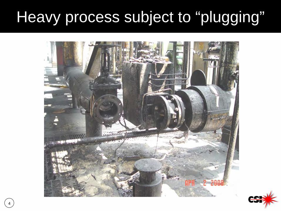
Heavy process subject to “plugging”

5
False sense of security
6
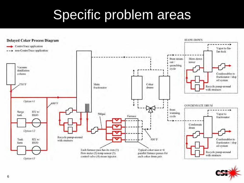
Specific problem areas
7
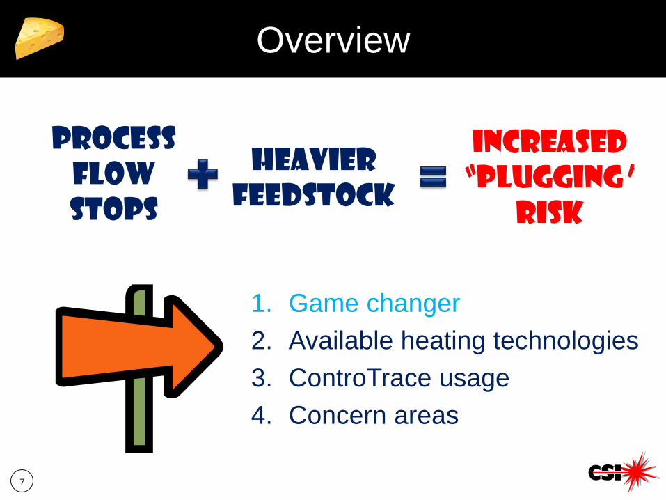
Overview
1. Game changer2. Available heating technologies3. ControTrace usage4. Concern areas
ProcessflowStops
Heavierfeedstock
INCREASED “plugging”
RISK
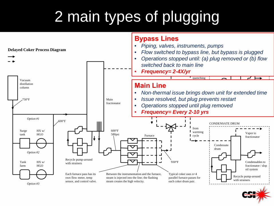
2 main types of plugging
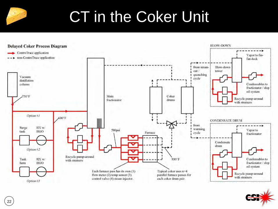
Vacuum distillation column
750°F
Surge tank
HX w/ HGO
Option #2
Tank farm
HX w/ HGO
Option #3
Option #1600°F
Main fractionator
Recycle pump-around with strainers
600°F580psi Furnace
Each furnace pass has its own flow meter, temp sensor, and control valve.
Typical coker uses n=4 parallel furnace passes for each coker drum pair.
930°F
Coker drums
from steam-out / quenching cycle
from warming cycle
Delayed Coker Process Diagram
Condensate drum
Condensables to fractionator / slop oil system
Vapor to fractionator
Recycle pump-around with strainers
Blow-down tower
Condensables to fractionator / slop oil system
Vapor to fin-fan deck
Recycle pump-around with strainers
CONDENSATE DRUM
BLOW-DOWN
Between the instrumentation and the furnace, steam is injected into the line; the flashing steam creates the high velocity.
Bypass Lines• Piping, valves, instruments, pumps• Flow switched to bypass line, but bypass is plugged• Operations stopped until: (a) plug removed or (b) flow
switched back to main line• Frequency= 2-4X/yr
Main Line• Non-thermal issue brings down unit for extended time• Issue resolved, but plug prevents restart• Operations stopped until plug removed• Frequency= Every 2-10 yrs
9
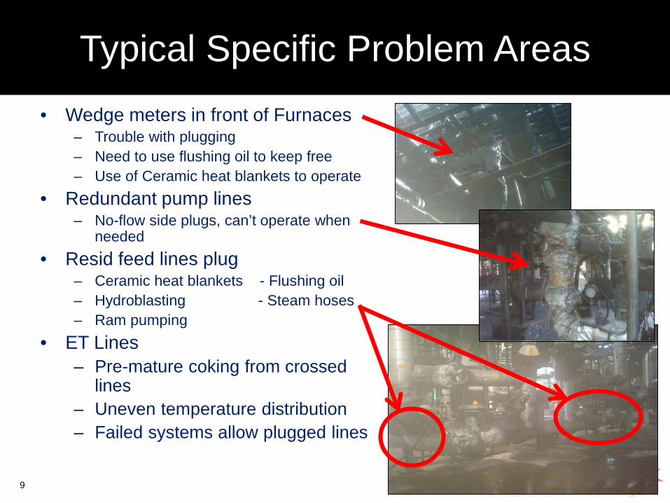
Typical Specific Problem Areas• Wedge meters in front of Furnaces
– Trouble with plugging– Need to use flushing oil to keep free– Use of Ceramic heat blankets to operate
• Redundant pump lines– No-flow side plugs, can’t operate when
needed• Resid feed lines plug
– Ceramic heat blankets - Flushing oil– Hydroblasting - Steam hoses– Ram pumping
• ET Lines– Pre-mature coking from crossed
lines– Uneven temperature distribution– Failed systems allow plugged lines
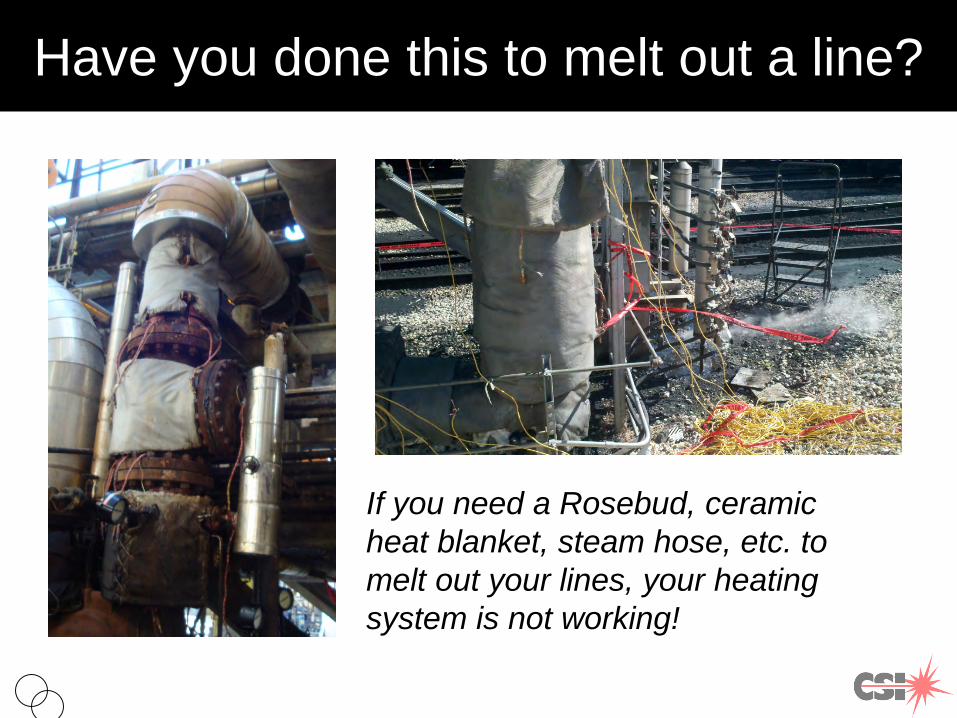
Have you done this to melt out a line?
If you need a Rosebud, ceramic heat blanket, steam hose, etc. to melt out your lines, your heating system is not working!
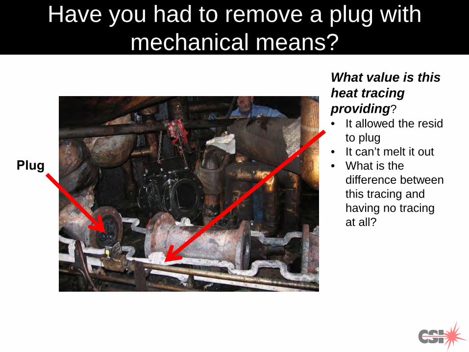
Have you had to remove a plug with mechanical means?
What value is this heat tracing providing?• It allowed the resid
to plug• It can’t melt it out• What is the
difference between this tracing and having no tracing at all?
Plug
12
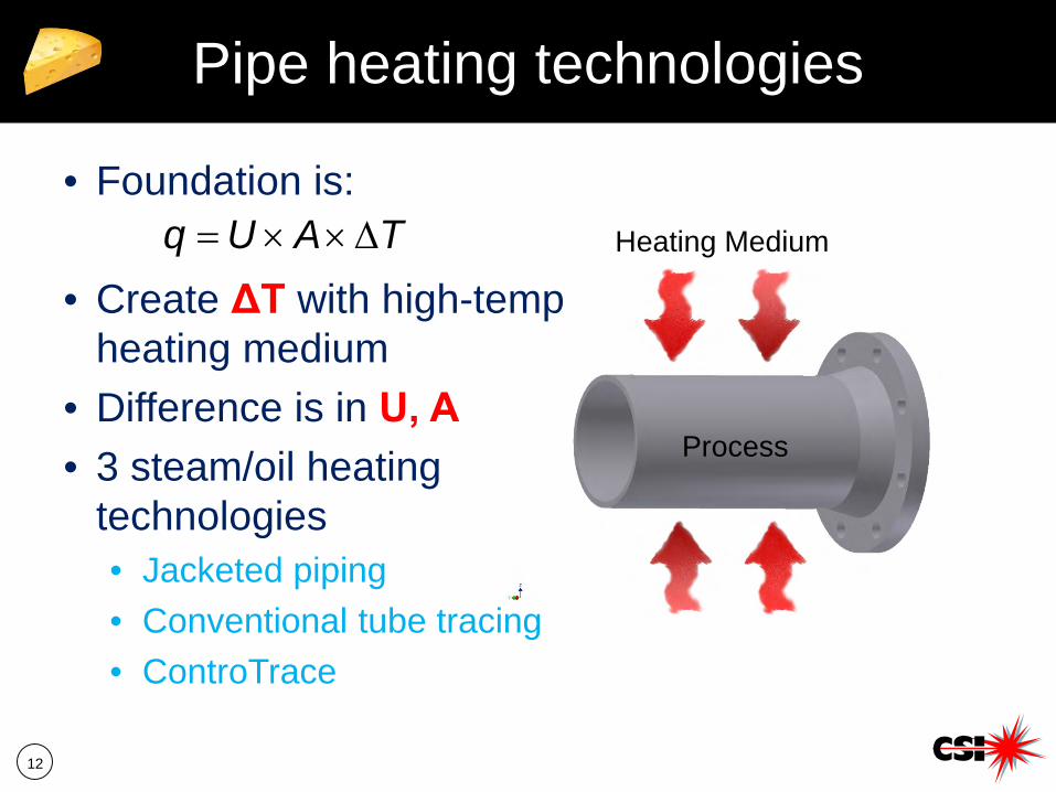
Pipe heating technologies
Heating Medium
Process
• Foundation is:
• Create ΔT with high-temp heating medium
• Difference is in U, A• 3 steam/oil heating
technologies• Jacketed piping• Conventional tube tracing• ControTrace
TAUq ∆××=
13
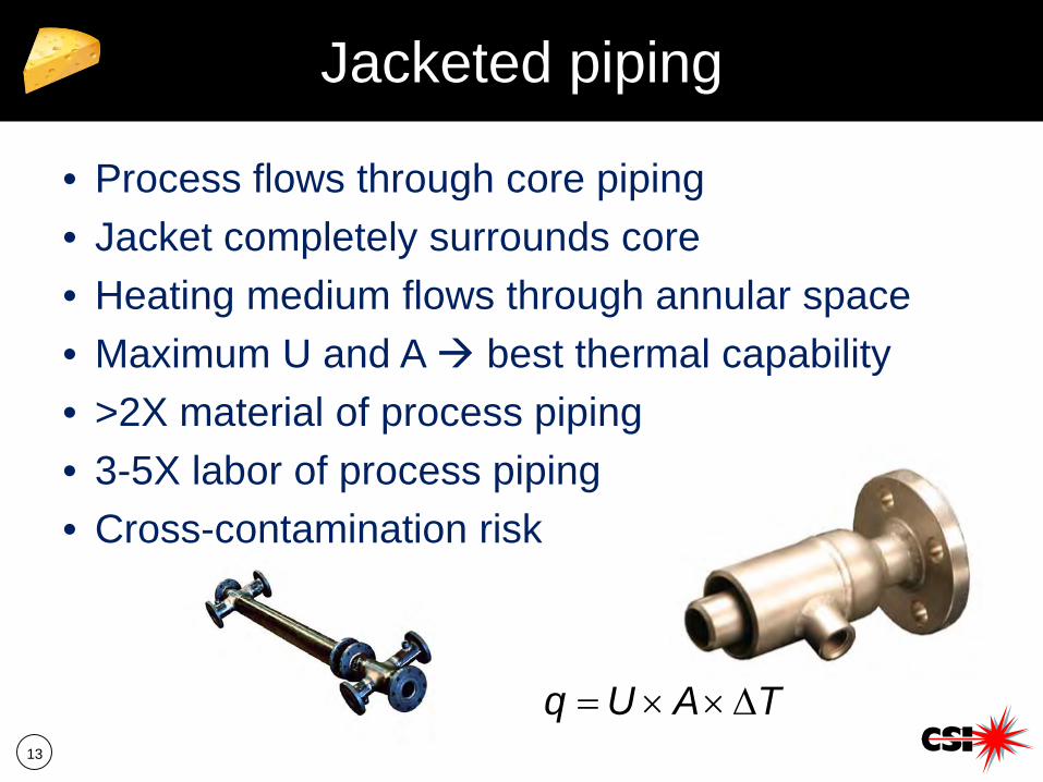
Jacketed piping
• Process flows through core piping• Jacket completely surrounds core• Heating medium flows through annular space• Maximum U and A best thermal capability• >2X material of process piping• 3-5X labor of process piping• Cross-contamination risk
TAUq ∆××=
14
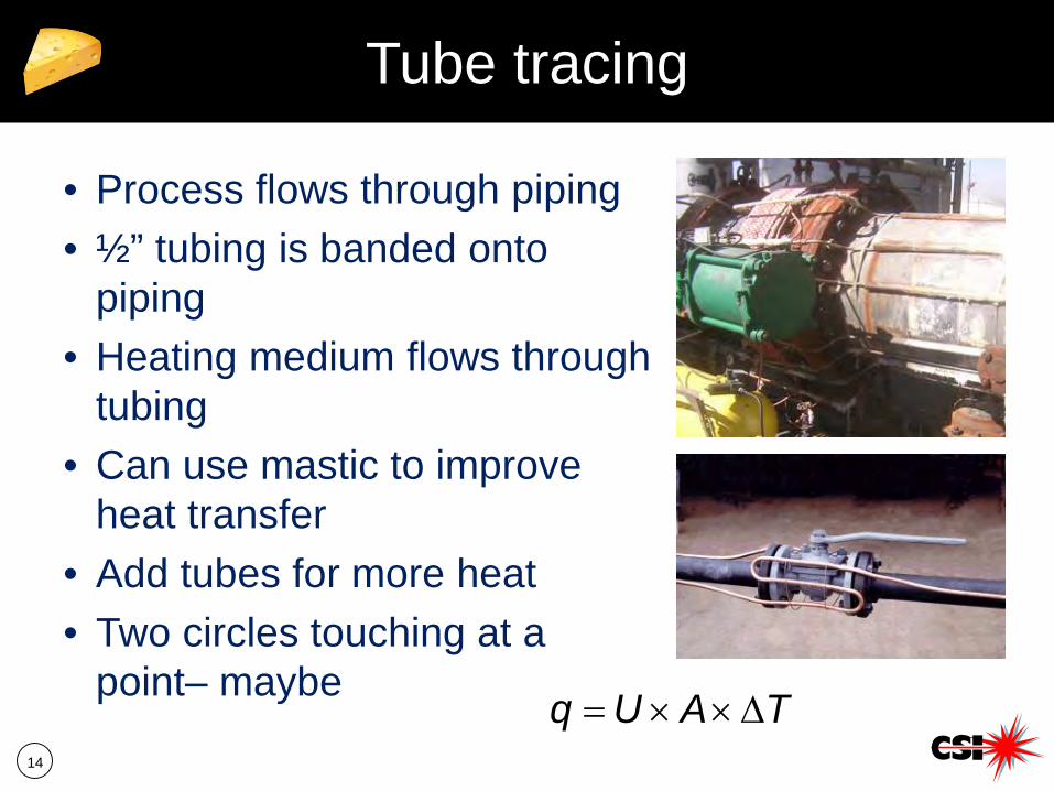
Tube tracing
• Process flows through piping• ½” tubing is banded onto
piping• Heating medium flows through
tubing• Can use mastic to improve
heat transfer• Add tubes for more heat• Two circles touching at a
point– maybe TAUq ∆××=
15
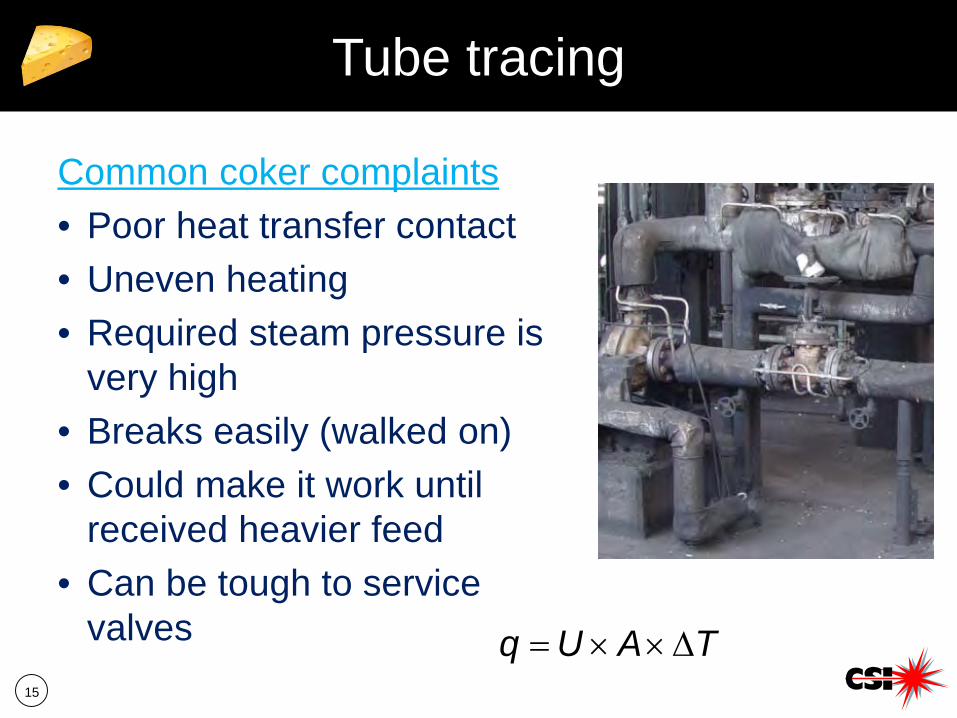
Tube tracing
Common coker complaints• Poor heat transfer contact• Uneven heating• Required steam pressure is
very high• Breaks easily (walked on)• Could make it work until
received heavier feed• Can be tough to service
valves TAUq ∆××=
16
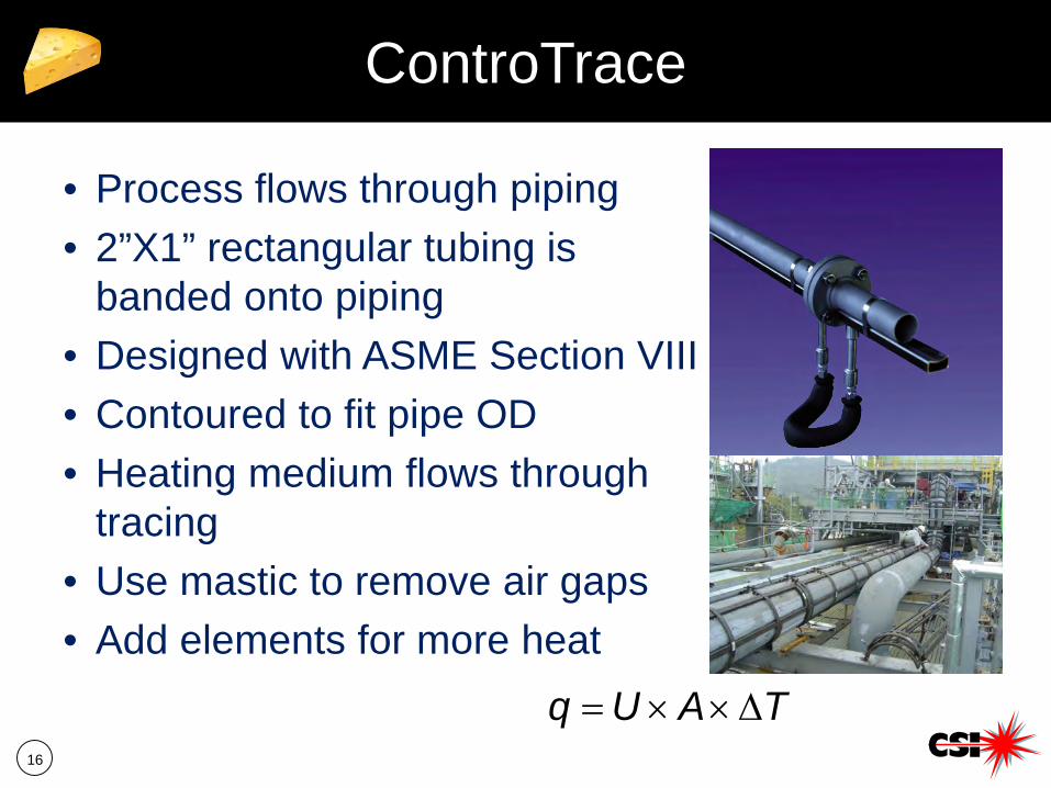
ControTrace
• Process flows through piping• 2”X1” rectangular tubing is
banded onto piping• Designed with ASME Section VIII• Contoured to fit pipe OD• Heating medium flows through
tracing• Use mastic to remove air gaps• Add elements for more heat
TAUq ∆××=
17
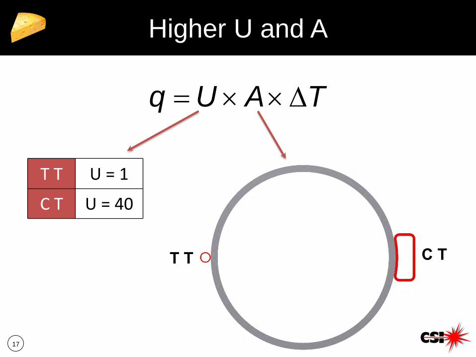
Higher U and A
TAUq ∆××=
T T U = 1
C T U = 40
T T C T
18
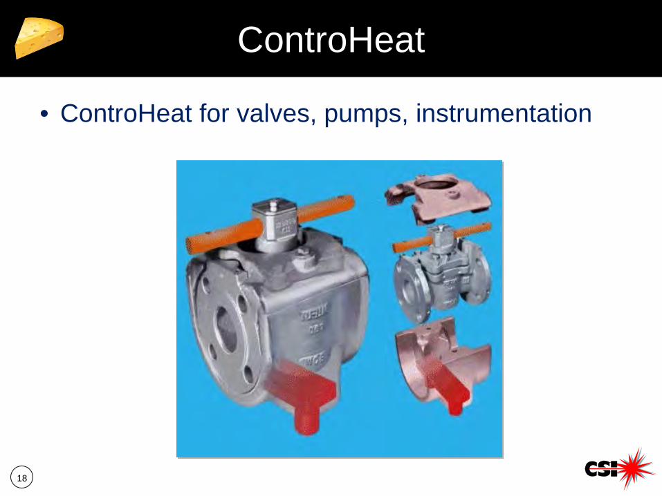
ControHeat
• ControHeat for valves, pumps, instrumentation
19
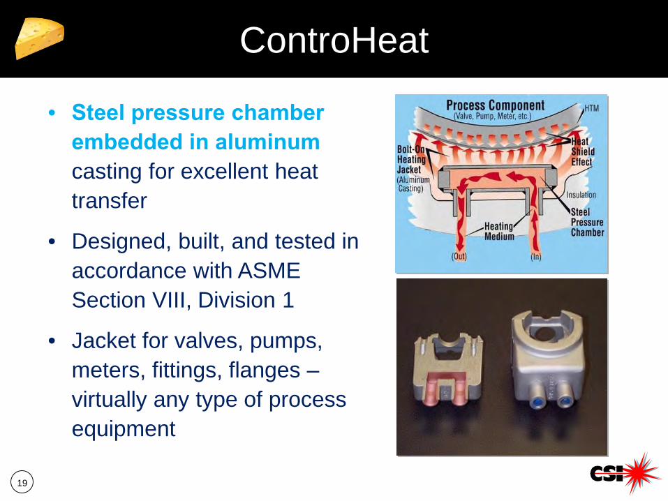
ControHeat
• Steel pressure chamber embedded in aluminum casting for excellent heat transfer
• Designed, built, and tested in accordance with ASME Section VIII, Division 1
• Jacket for valves, pumps, meters, fittings, flanges –virtually any type of process equipment
20
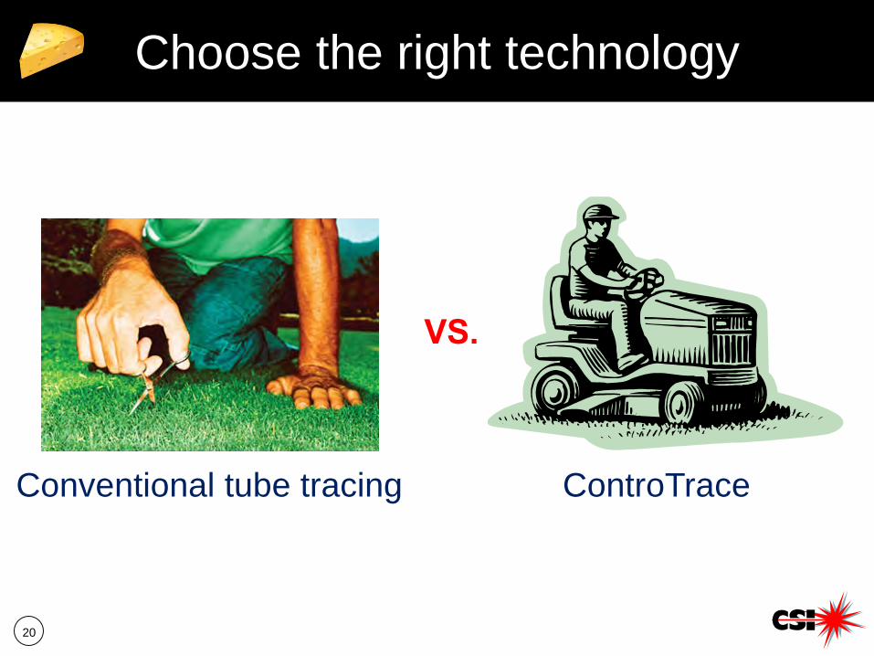
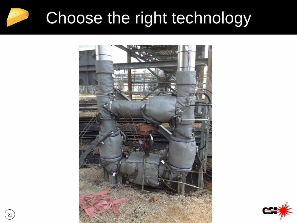
Choose the right technology
VS.
Conventional tube tracing ControTrace
21
Choose the right technology
22
CT in the Coker Unit
23
General recommendations
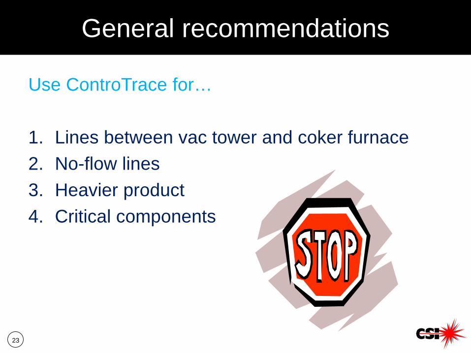
Use ControTrace for…
1. Lines between vac tower and coker furnace2. No-flow lines3. Heavier product4. Critical components
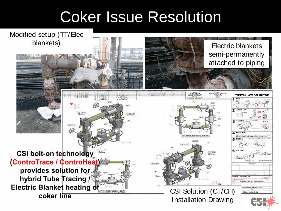
Coker Issue ResolutionModified setup (TT/Elec
blankets) Electric blankets semi-permanently attached to piping
CSI Solution (CT/CH) Installation Drawing
CSI bolt-on technology (ControTrace / ControHeat)
provides solution for hybrid Tube Tracing /
Electric Blanket heating of coker line
25
Specific target areas
1. Wedge flow meters prior to coker furnace2. Bypass/recirculation lines/strainers
a. Fractionatorb. Coke condensate drumc. Blow-down area
3. Drains to OWS throughout the unit
26
Summary
• Flowing process gives a false sense of security• Heavier feedstock changes the game• Coking experts are turning to more robust
heating system (ControTrace)• Specific target areas:
• Wedge flow meters prior to coker furnace• Bypass/recirculation lines/strainers• Drains to OWS throughout the unit
• Call us if we can help
27
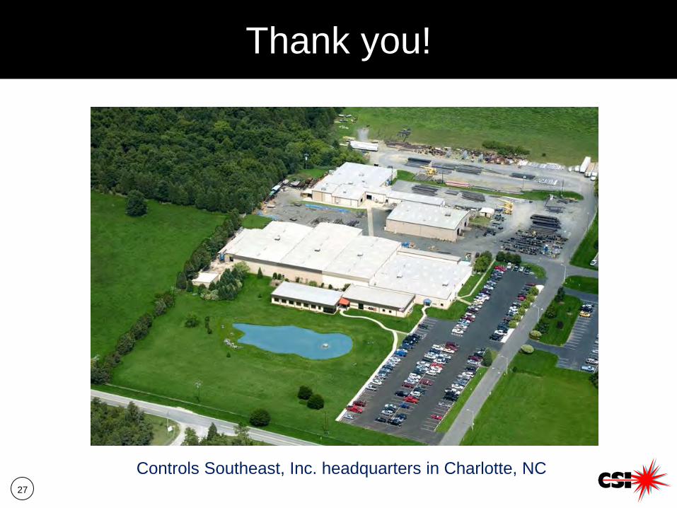
Thank you!
Controls Southeast, Inc. headquarters in Charlotte, NC
28
Contact information
Sean MathewControls Southeast, [email protected]
– Business Development for Controls Southeast, Inc.– Expertise in Steam Heating Technology– Piping Design & Steam Routing– MS Chemical Engineering, New Jersey Institute of
Technology