Embed Size (px)
Citation preview

Chapter 6
Related work
6.1 Introduction
In this chapter, I will briefly summarize work that is related to the topic of this thesis.
6.1.1 Organization of the chapter
One key aspect of this thesis is the exploration of how to integrate high-capacity,
all-optical circuit switches in the core of the network with a packet-switched access
network. This integration was achieved by monitoring user-flows. Section 6.2 sum-
marizes other approaches that also integrate circuit switching in the Internet. In
contrast, Section 6.3 presents some approaches that try to extend the packet switch-
ing paradigm to an all-optical core. Since this approach differs significantly from the
rest of this thesis, Section 6.3 has a discussion of its performance. Finally, Section 6.4
reviews other proposals for monitoring user flows.
6.2 Circuit switching in the Internet
As mentioned in Chapter 1, it is becoming increasingly difficult to build high-performance
packet-switched routers. This is due to several reasons, but the primary reason is be-
cause traffic is growing faster than electronic technology in general, and memory
112

6.2. CIRCUIT SWITCHING IN THE INTERNET 113
access speeds in particular. This calls for research into alternatives to packet switch-
ing. One of these alternatives, which has also been explored by other researchers,
is to integrate very high-capacity optical circuit switches in the core of an other-
wise packet-switched Internet. Four main dynamic signaling mechanisms have been
proposed to manage circuits in SONET/SDH and DWDM networks: Generalized
Multiprotocol Label Switching — GMPLS — (Section 6.2.1), Automatic Switched
Transport Network — ASTN — (Section 6.2.2), Optical Internetworking Forum —
OIF — (Section 6.2.3), and Optical Domain Service Interconnect — ODSI — (Sec-
tion 6.2.4). For each of these four approaches, a working group has defined signaling
mechanisms for managing circuits, but leave it to vendors to define how to monitor
traffic, when to trigger a new circuit establishment, and how much bandwidth to
allocate.
Two architectures have been proposed to help decide when to create a circuit and
how much bandwidth to give to it. The first is Optical Burst Switching — OBS —
(Section 6.3), in which a router at the edge of the network queues packets up to a
threshold and then establishes a circuit with an explicit or implicit connection release
time (also known as a burst). The second technique, proposed by Veeraraghavan et
al. (Section 6.2.6), defines an end-to-end, circuit-switched network that is parallel to
the packet-switched Internet. In their scheme only large files are transmitted across
the circuit-switched network.
The approach proposed in Chapter 4, TCP Switching, differs from both ap-
proaches above in that it (usually) piggybacks the creation of a circuit on the setup
phase of a TCP connection. In this respect, TCP Switching is similar to IP Switching
(Section 6.2.7), in which flows trigger the establishment of ATM virtual circuits. In
contrast, Chapter 5 focuses on the coarse circuits that interconnect boundary routers
around the core. It monitors user flows to estimate the required capacity for those
circuits.

114 CHAPTER 6. RELATED WORK
6.2.1 Generalized Multi-Protocol Label Switching (GMPLS)
Multi-Protocol Label Switching (MPLS) [165] is a packet-switching technique pro-
posed by the Internet Engineering Task Force (IETF) for traffic engineering that uses
labels to identify flows. These flows may be of any granularity, ranging from fine user
flows to coarse inter-router flows. Each flow follows a different label-switched path.
Labels are identifiers that are local to each link, and so a flow label has to be swapped
at each node with the local label for the next link.
GMPLS [7, 8] has been proposed within the Common Control and Measurement
Plane (ccamp) work group in IETF as a way to extend MPLS to incorporate circuit
switching in the time, frequency and space domains. Label-switched paths now may
consist of a chain of SONET/SDH channels, wavelengths or fibers with a minimum
capacity of at least 51 Mbit/s. The extensions of GMPLS define the signaling for the
establishment, routing, protection, restoration, deletion and management of coarse
label-switched paths that are circuit switched. As of April 2003, there are three pub-
lished Requests For Comments (RFC’s) on the standards track (one for the signaling
functional description and two for the signaling protocols — CR-LDP and RSVP-TE
—, which will be briefly described below). In addition, there are 20 Internet Drafts
in progress.
GMPLS uses the same mechanisms as MPLS to decide when to create or destroy
a circuit. GMPLS relies on either a User-to-Network Interface (UNI) or an MPLS
traffic-engineering server (TE server) to issue requests for new label-switched paths
(LSP’s) or to modify the characteristics of existing LSP’s. This traffic-engineering
server is vendor specific, and it is usually at the ingress of the packet-switched MPLS
network, where it collects traffic information to make its decisions. Alternatively, one
could use an approach similar to the one described in Chapter 5 to manage the LSP’s.
The differences between pure MPLS and the extensions of GMPLS come from
the nature of the circuit-switched channels that GMPLS uses. The two major dif-
ferences are, first, that in GMPLS the channel ID of the circuit-switched channels
(e.g., the slot number in a TDM frame or the wavelength ID) can be used as an ex-
plicit path label, and, second, that the data and control channels may be completely
decoupled in GMPLS (control information may be sent out-of-band, as opposed to

6.2. CIRCUIT SWITCHING IN THE INTERNET 115
an in-band MPLS shim header). In addition, GMPLS can only allocate bandwidth
in discrete and coarse amounts, and there are usually many parallel data channels
between two adjacent nodes (which was not originally considered in the IP or MPLS
control planes). Finally, in GMPLS, nodes may have restrictions on what labels can
be chosen (e.g., because of limited wavelength conversion capabilities).
The GMPLS extensions take all these differences into account. More precisely,
these extensions consist of:
• a new Link Management Protocol (LMP) that monitors the connectivity of the
data and control channels, and that localizes link or node failures [8, 103].
• enhancements to the link state advertisement of Open Shortest Path First
(OSPF) and Intermediate System-to-Intermediate System (IS-IS) routing pro-
tocols to advertise the availability of circuit-switched resources in the network
[8, 103].
• enhancements to Resource Reservation Protocol with Traffic Engineering (RSVP-
TE) and Constraint-Based Routing Label Distribution Protocol (CR-LDP) to
allow an LSP across a circuit-switched core to be requested with certain band-
width and protection characteristics [138, 7, 104].
When a GMPLS node decides to establish a new LSP, it sends downstream an
RSVP-TE PATH message (or a Label Request message if it uses CR-LDP) towards
the destination. This message contains a generalized-label request with the desired
bandwidth and (optionally) the desired protection level. The message is routed using
a constrained-based shortest-path-first algorithm that uses the link state information
flooded using OSPF or IS-IS, unless the PATH/Label Request message contains an
explicit route. The downstream node sends back an RSVP-TE Resv message (or
a Label Mapping message for CR-LDP) that includes the generalized label1 that
identifies the LSP.
1If the LSP is composed of several parallel channels, the downstream node may return one labelfor each channel.

116 CHAPTER 6. RELATED WORK
GMPLS does not specify whether RSVP-TE or CR-LDP should be used, and it
leaves to the vendors and carriers to decide. The main difference between RSVP-
TE and CR-LDP is that RSVP-TE uses “soft state” to manage the paths (circuits
are timed out unless the reservation is refreshed periodically), whereas CR-LDP uses
“hard state” (an explicit message is required to destroy active circuits). Soft state
has a higher signaling overhead and a looser control over resources, but it has a
simpler recovery strategy under complex failure scenarios. GMPLS has also extended
RSVP-TE to provide prompt notification of faults in the path.
Let us compare the signaling of GMPLS with that of TCP Switching (Chapter 4).
In both RSVP-TE and CR-LDP, the ingress has to wait for the round-trip time of a
two-way handshake to start sending data. In TCP Switching, the first packet in the
flow is used to establish the circuit, and, consequently, there is no delay in sending
the data. In addition, TCP Switching uses soft state without paying a penalty in
signaling overhead since any activity in the data channel automatically refreshes the
state of the circuit. In a sense, TCP Switching assumes semitransparent switches that
can understand whether a channel is being used or not. This hardware support is
not assumed to be present in GMPLS because many of its nodes switch information
transparently.
GMPLS can create both uni- and bi-directional LSP’s with a single PATH/Label
Request message. In contrast, TCP Switching (like traditional MPLS) only works
with purely unidirectional circuits. These bidirectional LSP’s are useful for several
important applications, such as telephony and private lines, and they also simplify
path protection by having the two directions share their fate.
In GMPLS, like in MPLS, LSP’s can be nested, and so a hierarchy of LSP’s can
be built to exploit the higher capacity of optical circuit switches, which have coarse
channel granularities. The hierarchy is composed of packet-switched LSP’s, TDM
circuits, wavelengths and fibers, as shown in Figure 6.1. This use of a hierarchy of
circuits is similar to the one proposed in Chapter 5.
Failure recovery is a very important requirement for carriers in GMPLS. GMPLS

6.2. CIRCUIT SWITCHING IN THE INTERNET 117
Fiber pathLambda
path
TDM
path
Packet-
switched
path
Figure 6.1: Hierarchy of label-switched paths in GMPLS.
can specify a different level of protection and restoration2 for each LSP. There are dif-
ferent levels of failure recovery depending on the provisioning of additional resources
(these resources can be pre-computed, pre-allocated or allocated on demand) and on
the level of overbooking (protection resources can be dedicated, shared or best effort).
In summary, GMPLS proposes another way of integrating circuit switching in
the core and packet switching in the edges. It focuses on the management of coarse
circuits between core routers (like Chapter 5). However, its scope is slightly different
than the contents of this thesis because it does not specify a control algorithm to
decide when to create circuits and with what capacity. GMPLS also deals with many
aspects, such as routing and path protection, that are out of the scope of this thesis.
2Protection refers to the extremely fast recovery from a failure (such as the 50 ms recovery timeof SONET/SDH rings), whereas restoration is a slower failure recovery that relies on the regularsignaling and routing mechanisms to re-establish the service.

118 CHAPTER 6. RELATED WORK
6.2.2 ASTN: Automatic Switched Transport Network
ASTN (Automatic Switched Transport Network) [168] and ASON (Automatic Switched
Optical Network) [167] are a set of Recommendations by Study Group 15 of the In-
ternational Telecommunications Union — Telecommunication Standardization Sector
(ITU-T) that specify the network architecture and the requirements for the signaling
and routing in automatic switched transport networks. The network architecture is
shown in Figure 6.2. The optical network has three planes: management, control and
data transport.
E-NNI
(BGP-4)
IP boundary router
UNI
(OIF)
Transport
plane
Control
plane
Management
plane
I-NNI
(GMPLS
or PNNI)
Network A Network B
Transport circuit switch
Figure 6.2: Network architecture of the Automatic Switched Transport Network(ASTN). UNI = User-to-Network Interface. I/E-NNI = Internal/External Network-to-Network Interface.
ASTN and ASON define the requirements in the control plane for the dynamic
circuit provisioning (within minutes) and for the network survivability, protection and
restoration. The goal is to specify a common control plane across multiple transport
technologies that provides quality of service and equipment interoperability across
domains and carriers.

6.2. CIRCUIT SWITCHING IN THE INTERNET 119
ASTN and ASON do not develop new protocols when existing ones will do. Con-
sequently, ASTN and ASON can either make use of GMPLS or PNNI [50, 117] as the
signaling protocol. Although eleven standards have already been produced (detailing
the architecture and the signaling requirements), the work of ASTN/ASON has not
been completed except for the general framework.
6.2.3 OIF: Optical Internetworking Forum
The Optical Internetworking Forum (OIF) [13] is an industry forum composed of
over 250 service providers and equipment vendors. It has defined a User-to-Network
Interface (UNI) that allows user devices (i.e. edge routers and ATM switches) to
dynamically request circuits between boundary devices through the circuit-switched
optical network core. These circuits are provisioned rapidly with various levels of cir-
cuit protection and restoration. The OIF UNI also specifies signaling for automatic
neighbor and service discovery, and for fault detection, localization and notification.
For the moment, the work on OIF’s UNI and IETF’s GMPLS remain very comple-
mentary. In the future, OIF plans to specify a Network-to-Network Interface (NNI)
that allows the direct interconnection of optical switches and networks from different
vendors. OIF has already produced version 1.0 of its UNI and also several specifi-
cations for the electrical and very-short-reach optical interfaces between chips and
between system elements. The OIF is not a formal standards body, but produces
detailed specifications that are presented to traditional standards bodies (IETF and
ITU-T) for adoption.
6.2.4 ODSI: Optical Domain Service Interconnect
The Optical Domain Service Interconnect (ODSI) is another industry forum that
was started by several startups almost at the same time as OIF. However, ODSI
lacked the participation by the large, established networking vendors and carriers,
and so after merging its efforts with the OIF signaling workgroup, ODSI ceased to
exist in late 2000. Like OIF, ODSI had also defined an optical UNI for edge routers
and switches to request circuits from the core. The key difference between the two

120 CHAPTER 6. RELATED WORK
specifications was that ODSI developed a TCP-based signaling protocol, whereas OIF
uses RSVP-TE or CR-LDP.
GMPLS, ASTN, OIF and ODSI share the same goal: to allow more dynamic,
automated and standardized optical networks. However, they address different is-
sues: ASTN has a top-down approach and focuses on the network architecture and
requirements. The other three proposals define the components of the architecture:
GMPLS specifies the routing, the topology and link state dissemination, and the NNI
signaling, and OIF and ODSI define the UNI signaling and work on the equipment
interoperability. The four efforts are aware of each other work and try to coordinate
their efforts. For more information, Clavenna [44] has written a good overview of the
differences between GMPLS, ASTN, OIF and ODSI.
6.2.5 Grid computing and CA*Net 4
Grid computing is a network of computation; i.e., a set of tools and protocols for
coordinated problem solving and resource sharing among pooled assets. These pooled
assets are known as virtual organizations, and they can be distributed around the
world. The shared resources are heterogeneous and autonomous (they may belong
different organizations), and their relation is temporary. The Global Grid Forum
is a research forum in distributed computing that mirrors IETF and that is trying
to standardize the grid-computing protocols and architectures under the Open Grid
Services Architecture (OGSA) [76]. Globus Toolkit [80] is an open-source reference
implementation of OGSA based on open standards from the web services world.
An example of a network designed for grid computing is CA*Net 4 [5]. It is part
of the Canadian national research network, and it is targeted towards universities,
research institutes and companies that need to exchange a good amount of data among
different locations either regularly (e.g., a company with multiple sites) or for limited
periods of time (e.g., for the duration of a joint project). CA*Net 4 is composed of
a set of unorganized, point-to-point wavelengths3 that are forwarded transparently
by DWDM circuit switches. The network clients are big and sophisticated; they
3These wavelengths carry either SONET/SDH channels of 2.5-Gbit/s or 10-Gbit/s, or Ethernetchannels of 1 Gbit/s or 10 Gbit/s.

6.2. CIRCUIT SWITCHING IN THE INTERNET 121
either lease or own a subset of the unorganized wavelengths, and they operate the
equipment that interconnects, translates and grooms those wavelengths to create
their own private network. The network client has complete control over its own
wavelengths and its network equipment, and it decides what gets added/dropped at
the different exchange points.
The most interesting part of CA*Net 4 design is the business model. Clients
only have to pay the capital cost of the dark fiber or wavelengths and the switching
equipment, instead of the usual monthly service charge paid to traditional ISPs.
Network connectivity is treated as a capital asset rather than a service as it is today.
In addition, clients can sublease part of the bandwidth (at the STS-1 or Gbit-Ethernet
granularity) in its own private circuit network through automated procedures.
In contrast, the proposals of Chapters 4 and 5 are for a public Internet infras-
tructure where resources are shared by all users. In addition, these two proposals
are geared towards the unsophisticated end user who wants a service similar to the
current public Internet without having to worry about the internals of the network,
or having to hold a lease on parts of the network.
6.2.6 Proposal by Veeraraghavan et al.
Veeraraghavan et al. [181] define a circuit-switched network that reaches the end
hosts and that runs in parallel to the packet-switched Internet. All traffic is sent
through the packet-switched network, except when a long file needs to be transferred.
Then, the end host creates a new end-to-end circuit in the circuit-switched network
that is used for the long trasfer. Since this end-to-end circuit is a constant bandwidth
channel that is solely reserved for that transfer, the transmission sees no losses due
to queueing or contention, no packet reordering, and no delay jitter. As a result,
a new transport protocol, called Zing, is proposed. This protocol has very simple
error and flow control mechanisms. Another characteristic of the system is that the
circuit-switching signaling is simple enough to be implemented in hardware.
The use of an end-to-end circuit-switched network has two problems: first and
most importantly, as shown in Chapter 3, circuit switching in the access network yields

122 CHAPTER 6. RELATED WORK
very bad response times for end users since large file transfers eventually monopolize
the link for long periods of time. Second, the cost of a second network with the
corresponding links and switches is very large, and so it is unlikely that this solution
will be widely deployed in the near future. This barrier to its deployment limits
its attractiveness, since one can only use Zing to exchange files with the few nodes
that are connected to the circuit-switched network. In contrast, the two approaches
presented in Chapters 4 and 5 do not require any flag days, in which all network
elements have to be upgraded or changed. Consequently, these two approaches can
be deployed incrementally without any changes in either the access networks or the
end hosts.
6.2.7 IP Switching
TCP Switching is most similar to IP Switching [129], in which user flows trigger the
establishment of ATM virtual circuits. The main difference is that TCP Switching
uses true circuits, as opposed to the use of the connection-oriented packet switching of
ATM [117]. Consequently, TCP Switching can benefit from the much higher capacity
of circuit switches.
IP Switching uses ATM virtual circuits, which is a packet-switching technique.
With virtual circuits, resources are not necessarily reserved as with true circuits.
Consequently, bandwidth is not wasted if the ATM virtual circuit remains active after
the associated flow has ended. With TCP Switching, bandwidth is reserved, and it
is wasted when unused. This wastage of bandwidth is relevant since typical flows in
the Internet last only a few seconds. For this reason, the recommended inactivity
timeouts of IP switching are above 30 seconds [108]; in contrast, TCP Switching uses
a timeout that is only slightly larger than the RTT (0.25-1 s).
6.3 Packet switching in the optical domain
Chapters 4 and 5 and Section 6.2 have described two ways of using high-capacity
all-optical circuit switches by integrating circuit-switched clouds with the rest of the

6.3. PACKET SWITCHING IN THE OPTICAL DOMAIN 123
Internet that uses packet switching. Several researchers have proposed all-optical
packet-switched routers instead.
El-Bawab and Shin [68] give an overview of the state of the art in the underly-
ing technologies that used for all-optical packet switching, such as technologies for
3R4 regeneration (SOA-based5 Mach-Zehnder interferometers, soliton transmission,
and self-pulsating distributed feedback lasers), packet delineation and synchronization
(fiber delay lines), packet header processing (O/E6 conversion, subcarrier multiplex-
ing, and Michelson interferometers), optical buffering (fiber delay lines), optical space
switching (SOAs, and LiNbO3 crossconnects), and wavelength conversion (SOAs with
cross-phase or cross-gain modulation, O/E/O conversion, and wave mixing).
El-Bawab and Shin state that major technological challenges need to be overcome
before optical packet switching is viable. Many of the enabling technologies are still
in the research and exploration stages, and so it is premature to build a commer-
cial all-optical router. Buffering and per-packet processing are the basis for packet
switching, and they remain the most important challenge to the implementation of
an optical router. Through reflections, refractions and diffractions, we know how to
bend, multiplex and demultiplex light, but we (still) do not know how to store as
much information in optics as with an electronic DRAM, or how to process infor-
mation in optics as fast as with an electronic ASIC. Current efforts in high-speed
optical storage and processing [109, 151, 178] are still too crude and complex to be
usable. With current optical storage approaches, information degrades fairly rapidly
(the longest holding times are around 1 ms), and these approaches can only be tuned
for specific wavelengths. In other areas, such as signal regeneration, packet synchro-
nization, space crossconnects and wavelength conversion, progress has been made,
but scalability, reliability and cost are still issues that need to be solved. In any
case, even if some of the technology on which optical packet switching depends is not
here yet, one can still study its performance to see what one can achieve once the
technology has been developed.
4Reamplification, Reshaping and Retiming.5Semiconductor Optical Amplifier.6Electronics-to-Optics.

124 CHAPTER 6. RELATED WORK
The family of solutions that does packet switching in optics can be further sub-
divided into two based on the size of the switching units: Optical Packet Switching
(OPS) switches regular IP packets, whereas Optical Burst Switching (OBS) deals
with “bursts”, units that are larger and encapsulate several IP packets.
6.3.1 Optical Packet Switching (OPS)
Optical Packet Switching (OPS) [186, 185] is the simplest and most natural extension
of packet switching over optics. It consists of sending IP packets directly over an all-
optical backbone. The biggest challenge that packets face in an optical switch is
the lack of large buffers for times of contention. As a rule of thumb, routers have
RTT×bandwidth worth of buffering [182], so that TCP congestion control works well.
For an OC-192c link and an average packet length of 500 bytes, this is equivalent to
a buffer space of 625,000 packets. In contrast, existing optical buffering techniques
based on fiber delay lines can accommodate at most a few tens of packets. With such
small buffers, the packet drop rate of an optical packet switch is quite high even for
moderate loads.
OPS tries to overcome the lack of buffers by combining two other techniques to
solve contention: wavelength conversion and deflection routing. If two packets arrive
simultaneously, and there are no local buffers left, the optical packet switch first tries
to find another free wavelength in the same fiber, and if it cannot find it, it will try
another fiber that does not have contention. The number of wavelengths is expected
to be between 4 and 512, and the number of neighboring nodes fewer than 10.
OPS has some shortcomings: one is that we do not have much room to solve the
contention. If we multiply the options given by the three dimensions (fiber delay lines,
wavelength conversion and path deflection), we have less than (10−50 packets/FDL)×(4 − 512 wavelengths/fiber) × (2 − 10 neighbors) = 80 − 256, 000 options. It may
seem to be close to the number of choices that we get from the electrical buffers
in a router (625,000 packets for a 10-Gbit/s link), but the number of degrees of
freedom is in fact much less since there are numerous dependencies that limit the
choice. Moreover, packets that are bounced to different paths may cause congestion

6.3. PACKET SWITCHING IN THE OPTICAL DOMAIN 125
in other wavelengths or other parts of the network, spreading local congestion across
larger areas of network. In addition, packets no longer follow the same path, and
so they may arrive out of order, which may be interpreted by TCP as losses due to
congestion, and TCP may thus throttle back its rate. Packet reordering within a TCP
session also causes unnecessary retransmissions, prevents the congestion window from
growing properly and degrades the quality of the RTT estimator in TCP [12, 17].
A problem that is perceived with OPS is that IP packet sizes are very short for
some optical crossconnects to be rescheduled. A 40-byte packet takes 32 ns to be
received on an OC-192c link, and only 8 ns on an OC-768c link. By contrast, MEMS
mirrors have tilting times of over 1 ms. For this reason, several researchers have
proposed using bigger switching units, called bursts, in an architecture called Optical
Burst Switching.
6.3.2 Optical Burst Switching (OBS)
Optical Burst Switching (OBS) was proposed in [155, 177], and it is a hybrid be-
tween packet switching and circuit switching. OBS pushes buffers to the edges of the
network, where electronic switches are, leaving no buffers in the optical core. OBS
gathers bursts of data at the ingress nodes of the backbone using large electronic
buffers until the node has enough data or a burst formation timeout occurs. At this
point, the burst is sent through the all-optical core. In general, the burst is preceded
by an out-of-band signaling message that creates a lightweight circuit with an explicit
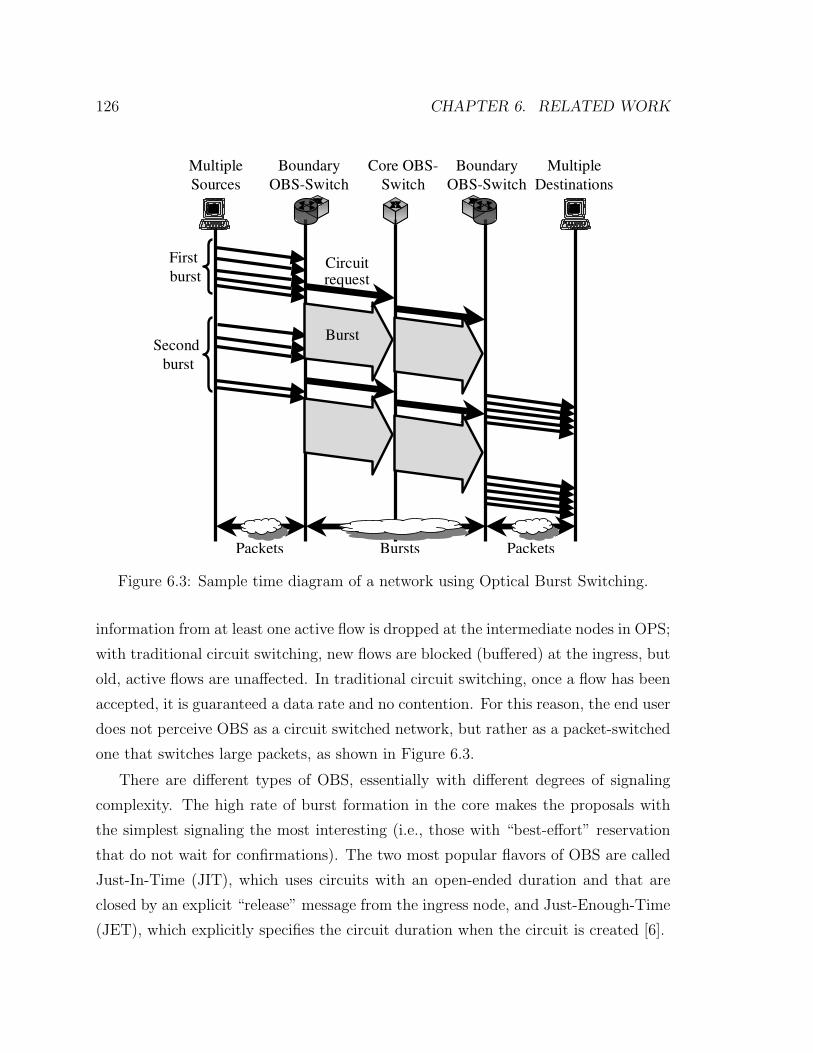
or implicit teardown time, through which the burst is sent, as shown in Figure 6.3. If
the circuit is successfully created, the burst traverses the circuit, and then the circuit
is destroyed once the burst has finished.
If during the circuit establishment there is no bandwidth left for the burst, the
node can either temporarily buffer the burst using the limited space of local fiber
delay lines or it can try to deflect the burst circuit to another wavelength or another
fiber. If none of these three options is available the incoming burst is then dropped
at that node. From the point of view of the user flows, the behavior of OBS is
closer to OPS than to traditional circuit switching techniques. If there is contention,
126 CHAPTER 6. RELATED WORK
Boundary
OBS-Switch
Core OBS-
Switch
Boundary
OBS-Switch
Multiple
Destinations
Multiple
Sources
Circuit request
Bursts PacketsPackets
Burst
First
burst
Second
burst
Figure 6.3: Sample time diagram of a network using Optical Burst Switching.
information from at least one active flow is dropped at the intermediate nodes in OPS;
with traditional circuit switching, new flows are blocked (buffered) at the ingress, but
old, active flows are unaffected. In traditional circuit switching, once a flow has been
accepted, it is guaranteed a data rate and no contention. For this reason, the end user
does not perceive OBS as a circuit switched network, but rather as a packet-switched
one that switches large packets, as shown in Figure 6.3.
There are different types of OBS, essentially with different degrees of signaling
complexity. The high rate of burst formation in the core makes the proposals with
the simplest signaling the most interesting (i.e., those with “best-effort” reservation
that do not wait for confirmations). The two most popular flavors of OBS are called
Just-In-Time (JIT), which uses circuits with an open-ended duration and that are
closed by an explicit “release” message from the ingress node, and Just-Enough-Time
(JET), which explicitly specifies the circuit duration when the circuit is created [6].

6.3. PACKET SWITCHING IN THE OPTICAL DOMAIN 127
With OBS, data is sent in batches as opposed to streamed as with regular IP or
traditional circuit switching, such as the proposals of Chapters 4 and 5. This has an
effect on TCP, since it relies on the packet timing to pace its transmissions. With
OBS, delivery is best effort, and so the burst may be lost. Since TCP considers the
loss of three consecutive packets as a sign of congestion, when burst sizes are long,
the loss of a burst is expensive because it makes TCP sources throttle back their
transmission rate. The effect of the burst loss rate is amplified by TCP. These two
interactions of OBS with TCP are only noticeable when bursts are very long, when
there are several packets belonging to the same user flow in each burst. TCP’s flow
and error control, thus, will set a limit on the maximum burst size that will depend
on the rates under consideration.
OBS uses electrical buffers at the ingress to aggregate regular IP packets destined
to the same egress node into bursts. The aggregation reduces the number of forward-
ing decisions that have to be done by the OBS so that they can be done electronically.
The trade-off for this is that OBS requires more buffering at the ingress of the optical
backbone than the optical circuit switching solutions because IP packets in OBS have
to wait until the next burst departs, whereas with circuit switching, packets belonging
to active circuits are sent as soon as they arrive. Furthermore, in TCP Switching, the
circuits have the same capacity as the access link, hence they are not the bottleneck
in the flow path. Consequently, queueing at the circuit head is unusual.
6.3.3 Performance of OPS/OBS
We can use the “end-user response time” to compare the performance of these two
related techniques. Let me start with OBS. According to [139], If we ignore retrans-
mission timeouts and operate in the absence of window-size limitations, we can write
the average throughput of TCP as:
Average throughput ∝ 1
RTT ·√
p·b
where RTT is the round-trip time, p is the packet drop probability and b is the
number of packets acknowledged per ACK message. The first thing to notice is that
the longer the burst size is, the more TCP data and acknowledgement packets get

128 CHAPTER 6. RELATED WORK
bundled together in bursts of OBS, which makes the value of b increase. In addition,
the small amount of buffers in OBS is not enough to solve the contention among
bursts, and so the drop rate is larger than with regular packet switching in electronic
form. For example, for a system load of 50% and four wavelengths per link, the drop
rates for open-loop traffic with OBS are between 2% and 0.1% [186, 188], whereas
the drop rates of electronic packet switching are typically several orders of magnitude
lower. Using an M/M/k/k + d model, where k is the number of wavelengths per
link and d the number of fiber delay lines, Yoo et al. [188] show that the drop rate
decreases exponentially with the number of wavelengths, k.
Furthermore, the burst-formation time in OBS increases the RTT, which reduces
the average throughput of TCP and, thus, increases the user response time.7 Simu-
lations using ns-2 suggest that even when we use a long burst formation latency of
50 ms, OBS leads to response times that are only about 10% slower than electronic
packet switching, and so one can conclude that their user response time performance
is comparable.
100 Mbit/s access link4 x 2.5Gbit/s wavelengths
OBS/OPS core
OBS/OPS
boundary router
Figure 6.4: Topology used in [186] to simulate the effect of Optical Packet and BurstSwitching on TCP. The core wavelengths were carrying bursty IP traffic in the back-ground.
The previous arguements about the burst/packet losses in OBS/OPS seem to
7Remember that TCP Switching also had an increase of the RTT because of the transmissiontimes over thin circuits. As the access-link rate increases in TCP Switching, the RTT increasebecomes negligible.

6.3. PACKET SWITCHING IN THE OPTICAL DOMAIN 129
question the end-user performance of OBS/OPS even under moderate loads because
of the high losses in the unscheduled optical cloud. However, some authors [86, 188]
have analyzed and performed open-loop simulations of OPS/OBS with unscheduled
optical clouds, and they have found that the losses of the system are acceptable if
enough wavelengths were available. For example, with a system load of 50% when
the number of wavelengths per link went from 4 to 32, the packet loss rate when from
2% to 4 · 10−5.
However, the close-loop, multiplicative-decrease-additive-increase congestion con-
trol algorithm of TCP can overreact to the clustered losses of OBS/OPS, and it can
make TCP cut its transmission rate very aggressively. Moreover, the burst formation
time has an important impact on the TCP throughput if it increases the connection
RTT [64]. Yao et al. [186] have simulated what happens when an FTP session con-
tends in an OPS/OBS, unscheduled optical core, such as the one shown Figure 6.4.
Figure 6.5 shows the response time of file transfers of 1.6 Mbytes. One can see how
the response time starts degrading with backbone loads of only 30%, and how, with
backbone loads of only 50%, the response times of those FTP sessions using OPS
is between 12 to 20 times worse than that of an unloaded network. Figure 6.5 also
shows how OBS can achieve a better performance by aggregating packets into bursts,
but the performance improvement is not enough to make the system usable under
reasonable link loads. However, something should be said about these results; the
system under consideration had only four wavelengths per link, so there is still room
for improving the performance by adding more wavelengths per link. Today it is
possible to switch over 320 wavelengths [173].
There have been several proposals [188, 186] to improve the dismal performance of
OSP/OBS by creating several traffic classes with strict priorities or by giving priority
to through traffic when it is contending with inbound traffic. The end result is that
the high-priority class sees a network load that is much smaller than the total link
load. It is as if all traffic of lower priority did not exist for the high priority class.
For eight wavelengths per link, the high-priority class gets an acceptable performance
(open-loop loss rate ≈ 4 · 10−5) at the cost of heavily hurting the low-priority class,
which gets an unacceptable performance, with loss rates of 20% for a total network

130 CHAPTER 6. RELATED WORK
IEEE Communications Magazine • September 2002 71
One of the main factors that affect TCP per-formance is the receiver window size, whose typi-cal values are 8, 32, or 64 kbytes. The aggregationthreshold C can also impact the TCP perfor-mance. When C is varied, the timeout value anddelay line size should be adjusted accordingly. Inour experiments, we set both the timeout periodand delay line length to be equal to the trans-mission delay of C packets with maximum length(1500 bytes each). The running time for eachdata point varied between 4 and 75 hours on a500-MHz Pentium III machine, depending ontransmitter load. The maximum transmitter loadwas 0.5 because larger values made the simula-tion time prohibitively long.
Figure 7a compares the file transfer timeTFTP for different TCP window sizes with elec-trical ingress buffering only and no aggregation.For reference, it also shows the TFTP withoutany background traffic for a client-server pairdirectly connected through a 100 Mb/s link withthe same propagation delay (i.e., a link length of60 km). Without aggregation, a window size of32 kbytes provides the best result because themeasured TCP round-trip time (RTT) is approx-imately 3 ms, and the TCP connection’s datarate is 100 Mb/s. (Note that the optimal windowsize should be the product of RTT and datarate.) The figure shows that with average trans-mitter load exceeding 0.4, TFTP increases consid-erably faster. This is because, for a givennetwork, TCP performance would deterioratesignificantly after the packet loss rate reaches acertain value [12].
Next, in Fig. 7b, we study the effect of theaggregation threshold by varying C to 10, 30,and 100 packets, with window size equal to 8kbytes. For transmitter load less than 0.2, theaggregation threshold does not seem to havemuch effect on system performance. As thetransmitter load increases, the 10-packet aggre-gation scheme has the lowest TFTP, followed bythe 30-packet and 100-packet schemes. The 10-packet scheme also performs better than theone without aggregation, indicating that aggre-gation improves TCP performance. However,with more packets aggregated, the performancedeteriorates because more queuing delay is
introduced in the packet aggregator. Intuitively,one would think a good aggregation schemeshould collect all the TCP segments sent withinone window size and send them out in oneaggregation packet. If this was the case, theaggregator would have to hold the first segmentfor at least the whole transmission delay of allthe segments in that window. Such a schemewould defeat the purpose of pipelining in theTCP sliding window mechanism, because thetotal transmission delay for the whole TCP win-dow is determined by the slowest link (in thisexample the 100 Mb/s link) regardless of howfast the rest of the network is. Therefore, thebenefit of traffic aggregation on TCP perfor-mance is not directly caused by aggregating TCPsegments within one window, but rather by itstraffic shaping effect (and the consequent reduc-tion of packet loss in the network).
CONCLUSION
This article presents a novel optical-electricalhybrid contention resolution scheme for OPSnetworks. This scheme exploits the inexpensiveelectrical buffer available at the ingress of thenetwork to buffer packets before they enter theoptical domain. Without introducing any notice-able extra latency under normal load, electricalingress buffering can significantly improve theefficiency of optical contention resolutionresources by allowing them to be used solely forresolving contentions among transit packets. Inthe example network, the networkwide packetloss rate is reduced by approximately 50 percentwith the hybrid approach. The article also inves-tigated the benefits of performing traffic aggre-gation at the ingress. An aggregation schemewas shown to lower PLR severalfold. Such ascheme can smoothe optical packet size andreduce the burstiness of Internet traffic. Basedon the proposed node architecture, the TCP per-formance was evaluated for an OPS network. Itwas observed that under normal network load,an OPS network can provide good-quality trans-port service to the TCP applications. Moreover,traffic aggregation can significantly improve theTCP performance because of the low PLR.
� Figure 7. A comparison of TFTP a) for different TCP window sizes; b) for different aggregation schemes.
Average offered transmitter load
0.4
30
TFT
P(S
)
40
50
20
10
0
0.50.30.20.10
DirectWin. 8 kb, no agg.Win. 32 kb, no agg.Win. 64 kb, no agg.
Average offered transmitter load
0.4
30
TFT
P(S
)
40
50
20
10
0
0.50.30.20.10
DirectWin. 8 kb, no agg.Win. 8 kb, agg. 10 pkWin. 8 kb, agg. 30 pkWin. 8 kb, agg. 100 pk
Figure 6.5: Response time of FTP sessions in Optical Packet and Burst Switchingusing TCP, as shown in Figure 7 in [186]. The diagram on the left studies the effectof the TCP receiver window size (8, 32 and 64 Kbytes), and the diagram on theright the effect of the burst size (1, 10, 30 and 100 packets). The “direct” curve usesregular packet switching with large electronic buffers in all nodes. The other curvesuse OBS/OPS with fiber loops, wavelength conversion and fiber deflection to resolvecontention.
load of 60%.
Even if, on average, link loads are low in the core of the network, it is not a
reasonable assumption on certain links (near hot spots) and at certain moments (e.g.,
after rerouting traffic following a link failure). Furthermore, hotspots and failures
happen in unpredictable locations at unpredictable times [90]. OBS/OPS would not
be able to provide the maximum performance where it is needed the most, unless the
OBS/OPS is extremely overprovisioned by having many wavelengths per link.
6.4 Flow Measurement
A key component of Chapters 4 and 5 is the monitoring of flows and the study of
their characteristics. This monitoring of flows has been done both off-line and on-line.
The off-line profiling of user flows has been used, first, to see whether the proposed
solutions make sense in the face of current Internet workloads and, second, to feed the
model in Section 5.4. On the other hand, the on-line monitoring of active flows has
been used to control the circuit-switched backbone in real time. Next, I will describe
6.4. FLOW MEASUREMENT 131
two approaches that can be used to study user flows.
6.4.1 RFC 2722 and NetFlow
RFC 2722 [22] provides a general framework for describing network traffic flows and
presents an architecture for traffic flow measurement and reporting. The purpose
of such flow-measurement system is to understand network usage and performance,
which is in general done off-line, rather than to control the network in real time.
Namely, such a flow measurement system can be used for network planning, perfor-
mance and QoS estimation, and per-user billing.
There are two related tools that use sampling of packets to study flows. Cisco
offers a feature in its routers called NetFlow [41] that logs in memory one packet out
of every N packet arrivals8 and later dumps the log to a permanent storage. There
are numerous commercial and open-source programs that analyze off-line the traces
sampled by NetFlow [171]. Duffield et al. [65] have proposed sampling flows with
a frequency that is the inverse of the flow size to decrease the number of samples
without introducing measurement errors.
6.4.2 Proposal by Estan and Varghese
Estan and Varghese [70] propose two methods that sample large flows (those that take
a non-negligible amount of the link capacity) more precisely. One method samples
packets at fixed arrival intervals, and it creates a filter for the flow of each sampled
packet. All subsequent packets will try that filter. Large flows are more likely to
have a filter in place when their packets arrive, and so they are more likely to be
matched and sampled. The other method hashes each arriving packet using multiple
hash functions. The value of each of the hash entries is increased with the packet
size. A packet belonging to a large flow finds that the values of all its hash entries are
large, whereas short flows most likely have some entry with a small value. These two
methods use less memory than Cisco’s NetFlow, and they accurately sample large
flows, but they ignore many small flows.
8A recommended sampling rate is 1 packet out of 100.

132 CHAPTER 6. RELATED WORK
As with the method listed in Section 4.3.3, the two methods described above
require the observation of every single packet in the link. The difference between the
two approaches is that Estan’s methods use fewer filters by focusing on big flows,
whereas the method of Section 4.3.3 uses many more filters because it measures
how many flows are currently active, whether they are large or small. This latter
information is then used to calculate the total flow capacity to properly size the
circuit in the core in real-time. However, small flows typically take less than 20%
of the aggregate rate, and so Estan’s two methods can provide a rough estimate
of the envelope of the total flow bandwidth with less state, but, as mentioned in
Section 4.3.3, the amount of state related to all active flows (big or small) is not a
big problem.
6.5 Conclusions
This chapter discusses other proposals that are related to this thesis. Some of these
proposals try to integrate circuit switching in the core within a packet-switched In-
ternet in a way that is similar to the one explored in this thesis: These approaches
map flows between boundary routers to circuits. They develop other aspects of this
integration that have not been addressed or elaborated in detail in this thesis, such
as the protection, restoration and routing of circuits, or the statistical monitoring of
flows. As such, these approaches could make use of the ideas developed in Chapters 4
and 5, and vice versa.
Other approaches, such as Optical Burst Switching and Optical Packet Switch-
ing, propose extending packet switching to all-optical switches.9 They require an
extremely overprovisioned network with hundreds of wavelengths per link to achieve
performances that are comparable to those of electronic packet switching. Even if all
the technological challenges that remain to get there are solved, the end user will not
see a better response time from the network than with a traditional circuit switching
9Even if OBS uses circuit switching to forward the bursts, from the point of view of performanceit behaves like a packet switching technology that switches very large packets (the bursts) usingcut-trough techniques.

6.5. CONCLUSIONS 133
solution, as pointed in Chapter 3.