Embed Size (px)
Citation preview

CHAPTER 5
PROJECT SCOPE OF WORK

5-1
CHAPTER 5
PROJECT SCOPE OF WORK
5.1 MINIMUM EXPRESSWAY CONFIGURATION 5.1.1 Project Component of the Project
The project is implemented under the Public-Private Partnership (PPP) Scheme in accordance with the Philippine BOT Law (R.A. 7718) and its Implementing Rules and Regulations. The project is composed of the following components;
Component 1: Maintenance of Phase I facility for the period from the signing of Toll Concession Agreements (TCA) to Issuance of Toll Operation Certificate (TOC) Component 2: Design, Finance with Government Financial Support (GFS), Build and Transfer of Phase II facility and Necessary Repair/Improvement of Phase I facility. Component 3: Operation and Maintenance of Phase I and Phase II facilities.
5.1.2 Minimum Expressway Configuration of Phase II 1) Expressway Alignment
Phase II starts at the end point of Phase I (Coordinate: North = 1605866.31486, East 502268.99378), runs over Sales Avenue, Andrews Avenue, Domestic Road, NAIA (MIA) Road and ends at Roxas Boulevard/Manila-Cavite Coastal Expressway (see Figure 5.1.2-1).
2) Ramp Layout
Five (5) new on-ramps and five 5) new off-ramps and one (1) existing off-ramp are provided as shown in Figure 5.1.2-1. One (1) on-ramp constructed under Phase I is removed. One (1) overloaded truck/Emergency Exit is provided.
One (1) on-ramp for NAIA Terminal III exit traffic and one existing off-ramp from Skyway for access to NAIA Terminal III.
One (1) on-ramp along Andrews Ave. to collect traffic jam from NAIA Terminal III traffic and traffic on Andrews Ave.
One (1) off-ramp to access to NAIA Terminal I and Terminal II.
One (1) on-ramp to collect traffic from NAIA Terminal I and Terminal II.
One (1) on-ramp and one (1) off-ramp from/to Roxas Boulevard.
One (1) on-ramp and one (1) off-ramp from/to Manila-Cavite Coastal Expressway.
One (1) existing on-ramp of Phase I is recommended to be removed.
3) Number of traffic lanes of the main expressway and ramps
Number of traffic lanes of the expressway is four (4) lanes (2-lane x 2-direction). Number of traffic lanes of all ramps is one (1) lane.

5-2
FIGURE 5.1.2-1 MINIMU EXPRESSWAY CONFIGURATION

5-3
4) Number of traffic lanes of at-grade roads during and after expressway construction
Number of traffic lanes of at-grade roads are as shown in Table 5.1.2-1 and Figure 5.1.2-2.
TABLE 5.1.2-1 NUMBER OF TRAFFIC LANES OF AT-GRADE ROADS
At-grade Road Existing No. of Traffic Lanes
No. of Traffic Lanes During Construction
No. of Traffic Lanes After
ConstructionEast Bound 3 (Before on-
ramp) 2 (After on-ramp)
2 3 Sales Avenue
West Bound 3 (Under off-ramp)2 (Under off-ramp)
2 3
East Bound 3-4 3 3-4 Andrews Avenue (Sales Ave. – Roundabout) West Bound 3 3 3
East Bound 3 2 3 Andrews Avenue (Roundabout – Domestic Road) West Bound 3 2 3
North Bound 3 2 3 Domestic Road South Bound 3 2 3 East Bound 4 2 4 NAIA (MIA) Road (Domestic
Road – Quirino Avenue) West Bound 4 2 4 East Bound 4 2 4 NAIA (MIA) Road (Quirino
Avenue – Roxas Boulevard) West Bound 3 2 3
FIGURE 5.1.2-2 NUMBER OF TRAFFIC LANES AT-GRADE ROADS

5-4
5) Vertical Clearance for Expressway and At-grade Roads
Vertical clearance for expressway and at-grade roads is as follows; Desirable Vertical Clearance: 5.00 m Absolute Minimum Vertical Clearance (Note-1): 4.88 m Note-1: applicable only to the section controlled by NAIA Navigational Height Limit.
6) Pedestrian Overpass Bridge
Existing pedestrian overpass bridges are treated as follows; Pedestrian Overpass Bridge along Andrews Avenue: To remain as is.
Pedestrian Overpass Bridge along Domestic Road: To be removed and converted to the
pedestrian crossing with traffic light.
Pedestrian Overpass Bridge near the Intersection between Domestic Road and NAIA Road:
To be removed and replaced with new one near the intersection.
Pedestrian Overpass Bridge at the Intersection between NAIA Road and Roxas Boulevard:
To remain as is.
Minimum vertical clearance on the pedestrian overpass bridge is 2.00 m.
7) NAIA Navigational Height Limit
NAIA navigational height limit is shown in Figure 5.1.2-3 which shall be confirmed by Civil Aviation Authority of the Philippines (CAAP).

5-5
UR
E
FIGURE 5.1.2-3 HEIGHT LIMIT ALONG ANDREWS AVE. AND DOMESTIC ROAD AND AVAILABLE NET HEIGHT

5-6
5.2 MINIMUM DESIGN STANDARDS 5.2.1 Geometric Design Standards
1) Design Standard
The following standard is mainly used as reference in NAIA Express Highway Phase II design. A Policy on Geometric Design of Highways and Streets, AASHTO 2004 Highway Safety Design Standards Part 1 Road Safety Design Manual, May 2004, DPWH Japan Road Association, Road Structure Ordinance,2004 Highway design manual, Metropolitan Expressway Co., Ltd., Japan Highway design manual, NEXCO, Japan
2) Design Speed
Main Expressway Alignment
Minimum design speed of the main expressway alignment is 60 km/hour, except for the short section from Sales Avenue to Andrews Avenue of which design speed is 50km/hour.
(a) On and Off Ramps
The on and off ramp design speed is 40kph.
3) Design Vehicle
A single-unit truck is considered as design vehicle of the main alignment and ramps.
4) Geometric Design Standards
Geometric design standards are summarized in Table 5.2.1-1 and Table 5.2.1-2. 5) Typical Cross Section
Typical cross sections of main expressway for normal section, main expressway for NAIA navigational height limit section and a ramp are shown in Figure 5.2.1-1.

5-7
TABLE 5.2.1-1 GEOMETRIC DESIGN STANDARDS FOR NAIAX PHASE-II: MAIN EXPRESSWAY ALIGNMENT
Geometric Design Standards: Main Expressway Alignment
1. Cross Section Elements
2.Horizontal Alignment
3. Vertical Alignment
4.Curve Radius and Widening (per 1 carriage way)
AASHTO 2004 p211 ,p213 adjusted to SU, roadway width 7.0m
Values less than 0.6m may be disregarded
Widening(m)
120 90
0.6 0.6 0.6 0.7
300400
0.1
Design Vehicle - SU
Page 147, exhibit 3-15, ASSHTO 2004
Normal Crossfall % 2.00
Item Unit Standard
60
Maximum relative gradients % 0.60
Maximum super elevation %
Super elevation
Remark
0.5m shall be adopted for NAIA Navigational height limit section and section over Sales Ave.
Design Speed kmh
Item Unit Standard Absolute Minimum
Unit
2000(1400)JPN Standard
page 62, super elevation DPWH, Road Safety Design Manual
page 168, exhibit 3-26, ASSHTO 2004
Remark
% exhibit 3-26
6.00
Outer Shoulder Strip 〃 1.50 0.5
Inner Shoulder Strip 〃
Lane Width
Median Width 〃 1.00
Item Unit
Page 69, Table 16.4 DPWH Road Safety Design Manual
Item
Number of Lanes nos 2
m 3.50
%
18.0
Passing Sight Distance 〃 410
Min.K value〃
〃
1030page 168, exhibit 3-26, ASSHTO 2004 (2.0%),JPN Standard
30
page 53, table 16.1 DPWH Road Safety Design Manual
11.5
Remark
Page 61, Figure 16.3 DPWH Road Safety Design Manual
85 75page 56, Table 16.3, DPWH Rad Safety Design Manual
123
Standard Absolute Minimum
0.50
Standard Absolute
〃
500
5 7
Absolute Maximum
0.3 0.5
JPN Standard
Page 53,Table 16.1 DPWH Road Safety Deisgn Manual
Remark
1500(1000) JPN Standard
Page 636, DPWH Design Guidelines, Criteria and Standards Vol II
140 130
Crest
Sag
Radius Curve(m)
Min. Vertical Curve Length 60
250 200 150
m
〃
18.0
Min.Radius not requiring
Transition Curve
Superelevation run off
〃
1/125
%
0.20.2
Stopping Sight Distance
Max.Composition Grade
m
Max Vertical Gradient
Minimum Radius
Min. Transition Curve Length

5-8
TABLE 5.2.1-2 GEOMETRIC DESIGN STANDARDS FOR NAIAX PHASE-II: RAMPS
Geometric Design Standards: Ramps
1. Cross Section Elements
2.Horizontal Alignment
3. Vertical Alignment
4.Curve Radius and Pavement Width
Pavement Width (m)
〃
Radius (m)
5.5
Min. Vertical Curve Length
6.0 5.6
11.5
15
60
Stopping Sight Distance
Max.Composition Grade
〃
%
Max Vertical Gradient
Min.K valueCrest
Sag
〃
〃
30 50 75
5.1 5.1
125 150
5.3
Item Unit Standard Absolute Minimum
m
5.2 5.2
25
Page 61, Figure 16.3 DPWH Road Safety Design Manual
Remark
7
page 56, Table 16.3, DPWH Rad Safety Design Manual
Design Vehicle - SU
Page 69, Table 16.4 DPWH Road Safety Design Manual
PCCP
Exhibit 2-4, p22 AASHTO 2004
50
Absolute Minimum
page 168, exhibit 3-26, ASSHTO 2004
0.5m for 2 lanes Ramp
Remark
-
1
0.50
%
〃
〃
Minimum Radius
Min. Transition Curve Length
Min.Radius not requiring
Transition Curve
Superelevation run off
Passing Sight Distance 〃 270
Pavement Type
Unit StandardItem
3.50
Maximum super elevation %
Normal Crossfall %
〃
2.00
6.00
Median Width
Lane Width
Maximum relative gradients % 0.66
Super elevation % exhibit 3-26
Page 147, exhibit 3-15, ASSHTO 2004
6
JPN Standard
page 168, exhibit 3-26, ASSHTO 2004 (2.0%)
page 62, super elevation DPWH, Road Safety Design Manual
Remark
1/125
22
525
page 53, table 16.1 DPWH Road Safety Design Manual
Page 53,Table 16.1 DPWH Road Safety Deisgn Manual
Standard Absolute Minimum
43
40
Inner Shoulder Strip
Number of Lanes nos
〃
Outer Shoulder Strip 〃 2.00 0.5
m
CaseII, Condition A, p839 AASHTO 2004
( )is recommended value
( )is recommended value
9.0
6.0
Page 636, DPWH Design Guidelines, Criteria and Standards Vol II
100
Remark
Item Unit Standard Absolute Maximum
Item Unit
Design Speed 〃

5-9
FIGURE 5.2.1-1 TYPICAL CROSS SECTION
5-10
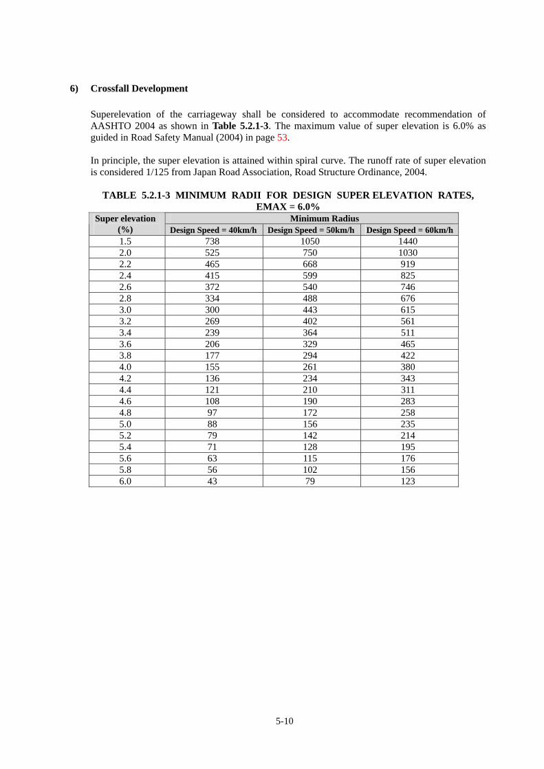
6) Crossfall Development
Superelevation of the carriageway shall be considered to accommodate recommendation of AASHTO 2004 as shown in Table 5.2.1-3. The maximum value of super elevation is 6.0% as guided in Road Safety Manual (2004) in page 53. In principle, the super elevation is attained within spiral curve. The runoff rate of super elevation is considered 1/125 from Japan Road Association, Road Structure Ordinance, 2004.
TABLE 5.2.1-3 MINIMUM RADII FOR DESIGN SUPER ELEVATION RATES, EMAX = 6.0%
Minimum Radius Super elevation (%) Design Speed = 40km/h Design Speed = 50km/h Design Speed = 60km/h1.5 738 1050 1440 2.0 525 750 1030 2.2 465 668 919 2.4 415 599 825 2.6 372 540 746 2.8 334 488 676 3.0 300 443 615 3.2 269 402 561 3.4 239 364 511 3.6 206 329 465 3.8 177 294 422 4.0 155 261 380 4.2 136 234 343 4.4 121 210 311 4.6 108 190 283 4.8 97 172 258 5.0 88 156 235 5.2 79 142 214 5.4 71 128 195 5.6 63 115 176 5.8 56 102 156 6.0 43 79 123

5-11
7) Minimum Curve length The length of the spiral curve recommendation is to take for 2 seconds of the design speed by AASHTO 2004. 40km/h: Ld=11.1(m/s) x 2(sec)=22.2m(22m) 50km/h: Ld=13.9(m/s) x 2(sec)=27.8m(28m) 60km/h: Ld=16.7(m/s) x 2(sec)=33.3(33m)
The minimum length of spiral curve for runoff of the super elevation is calculated as shown in Table 5.2.1-4. This value is applied when it is larger than “Ld”. The design shortens spiral curve length where topographical and control condition is critical by allowing runoff till 2.0% at Ts points.
TABLE 5.2.1-4 MINIMUM SPIRAL CURVE LENGTH Radius Super elevation(%) We(m) e Ls e(min)* Ls(min)* Remark
92 6.00 8.0 0.480 60.000 0.320 40.000 50kmh123 6.00 8.0 0.480 60.000 0.320 40.000 60kmh190 5.60 8.0 0.448 56.000 0.288 36.000 60kmh200 5.40 8.0 0.432 54.000 0.272 34.000 60kmh250 4.60 8.0 0.368 46.000 0.208 26.000 60kmh300 3.80 8.0 0.304 38.000 0.144 18.000 60kmh500 2.80 8.0 0.224 28.000 0.064 8.000 60kmh
* e(min) and Ls(min) is the value when runoff till 2.0%(same as crossfall) at Ts points
* This value is only applied where topo and horizontal control condition is critical.
We = 8000

5-12
8) Speed Change Lanes
The deceleration and acceleration length requirements are calculated based of AASHTO (2004) as shown in Table 5.2.1-5 and Table 5.2.1-6.
(a) Deceleration Lane Length and Acceleration Lane Length
TABLE 5.2.1-5 DECELERATION LENGTH
L (meters) for Design Speed of Exit Curve, V’ (km/hr) Stop
Condition 20 30 40 50 60 70 80
For Average Running Speed on Exit Curve, V’a (km/hr)
Highway Design
Speed, V (km/hr)
Speed Reached,
Va (km/hr) 0 20 28 35 42 51 63 70
50 47 75 70 60 45 - 60 55 95 90 80 65 55 - 70 63 110 105 95 85 70 55 - 80 70 130 125 115 100 90 80 55 - 90 77 145 140 135 120 110 100 75 60 100 85 170 165 155 145 135 120 100 85 110 91 180 180 170 160 150 140 120 105 120 98 200 195 185 175 170 155 140 120
Where:
V = Design Speed of Tollway (km/hr)
Va = Average Running Speed on Tollway (km/hr)
V’ = Design Speed of Exit (km/hr)
V’a = Average Running Speed on Exit Curve (km/hr)
TABLE 5.2.1-6 ACCELERATION LENGTH L (meters) for Entrance Curve Design Speed, V’ (km/hr)
Stop Condition
20 30 40 50 60 70 80
And Initial Speed, V’a (km/hr)
Highway Design
Speed, V (km/hr)
Speed Reached,
Va (km/hr) 0 20 28 35 42 51 63 70
50 37 60 50 30 - - 60 45 95 80 65 45 - - 70 53 150 130 110 90 65 - - 80 60 200 180 165 145 115 65 - - 90 67 260 245 225 205 175 125 35 - 100 74 345 325 305 285 255 205 110 40 110 81 430 410 390 370 340 290 200 125 120 88 545 530 515 490 460 410 25 245
Where:
V = Design Speed of Tollway (km/hr) Va = Average Running Speed on Tollway (km/hr) V’ = Design Speed of Entrance Curve (km/hr) V’a = Initial Speed on Entrance Curve (km/hr)

5-13
TABLE 5.2.1-7 (1) SPEED CHANGE LANE ADJUSTMENT FACTORS AS A FUNCTION OF GRADE
Highway Design Speed, V (km/hr)
Ratio of Length on Grade to Length on Level for Design Speed of Turning Curve (km/hr)
All Speeds 3 to 4% Upgrade 0.90
3 to 4% Downgrade 1.20
All Speeds 5 to 6% Upgrade 0.80
5 to 6% Downgrade 1.35
TABLE 5.2.1-7 (2) S5PEED CHANGE LANE ADJUSTMENT FACTORS AS A FUNCTION OF GRADE
Ratio of Length on Grade to Length on Level for Design Speed of Turning Curve (km/hr)
Highway Design Speed, V (km/hr) 40 50 60 70 80 All Speeds
3 to 4% Upgrade 3 to 4%
Downgrade60 1.3 1.4 1.4 0.70 70 1.3 1.4 1.4 1.5 0.65 80 1.4 1.5 1.5 1.5 1.6 0.65 90 1.4 1.5 1.5 1.5 1.6 0.6 100 1.5 1.6 1.7 1.7 1.8 0.6 110 1.5 1.6 1.7 1.7 1.8 0.6 120 1.5 1.6 1.7 1.7 1.8 0.6
5 to 6% Upgrade 5 to 6%
Downgrade60 1.5 1.5 0.6 70 1.5 1.6 1.7 0.6 80 1.5 1.7 1.9 1.8 0.55 90 1.6 1.8 2.0 2.1 2.2 0.55 100 1.7 1.9 2.2 2.4 2.5 0.5 110 2.0 2.2 2.6 2.8 3.0 0.5 120 2.3 2.5 3.0 3.2 3.5 0.5
(b) Diverging Taper
*Vertical Gradient less than 3.0%
Design Speed 60 km/hr (16.67 m/s)
Lane width 3.5m
Diverging Taper 58m
Diverging Taper- 0.6m/s for through lane merge - 1.0m/s for acceleration lane merge

5-14
Minimum Deceleration and Acceleration Lanes Deceleration lane
*Vertical Gradient less than 3.0%
Acceleration lane
*Vertical Gradient less than 3.0%
9) Maximum Gradient
For the main expressway alignment with design speed of 60kmh, the maximum vertical gradient could be 7% by referring to Road Safety Manual (2004 DPWH), however, desirable max gradient is 5%. For On and Off Ramps, the maximum gradient recommended is 6.0%, while absolute maximum gradient is 7.0%.
Diverging Taper 58mDeceleration 65m
Minimum Deceleration lane = 123m
Merging Taper 58mAcceleration 45m
Minimum Acceleration lane = 103m

5-15
5.2.2 Minimum Design Standards for Structure
1) Structure Design Standard
The Structure Design Standard shall be in accordance with the following codes and guidelines: AASHTO Standard Specifications for Highway Bridges 17th edition 2002, DESIGN Guidelines Criteria and Standard for Department of Public Works And Highways, Basic Specifications – DPWH Standard Specifications 2004, Highways, Bridges and Airports Alternatively, Japanese Standards also will be adopted as the structure design standards.
2) Loading Specifications
Structure shall be designed to carry the following loads and forces:
1) Dead Load
2) Live Load
Live Load shall be MS18 (HS-20-44)
3) Impact Load I = 15.24/(L+38)
4) Sidewalk Live Load 4.07 KPa of sidewalk area
5) Earthquake Load A = 0.5g, Seismic Performance Category = D
6) Earth Pressure Coulomb’s Formula
7) Wind Load For the Superstructure design, 2,394Pa of wind load shall be applied horizontally at right angle to the longitudinal axis of girders and beams.
8) Thermal Forces The range of temperature shall be as follows: 17.8 °C to 48.9 °C 16.7 °C temperature rise 22.2 °C temperature fall
3) Seismic Design
Seismic Design shall be in accordance with AASHTO Standard Specifications Division I-A. Acceleration coefficient of 0.50g shall be adopted to consider importance classification and past/recent experience in the Philippines.
4) Materials All materials to be used in the project shall conform to DPWH Standard Specifications (2004), and AASHTO Code.

5-16
a) Concrete
DESCRIPTION
fc’ (Min.)
MPa
MAXIMUM SIZE OF CONCRETE AGGREGATES
(mm)
MINIMUM CONCRETE
COVER (mm)
a. Superstructure
- Deck slabs, Diaphragms
28 20 Deck slab with BWS Top: 50 Bottom: 50 Others: 35
- Sidewalk, railings, parapets, medians
21 20
- PSC I-Girders 38 20 PSC I-Girders: 35
b. Substructure
- PC Pier copings, columns, footings
28 20
- PSC Pier copings, rotating pier head
38 20
- RC Abutment walls, footings
28 20
- Bored piles 28 20
Pier Copings, RC & PSC: 50 PSC Hammerheads: 40 RC columns: 50 Footing and Bored Piles: 75 Abutment Walls: 50
c. Earth covered RC Box structures
28 20 Earth covered Box structures: 50
d. Other concrete (normal use)
21 20
e. Lean concrete (for leveling)
17 25
f. Non shrink grout 41 40
b) Reinforcement Steel
All pre-stressing steel shall be high strength stress relieved wires or strands with an ultimate stress, fs’=1860 MPa Pre-stressing steel shall be free from kinks, notches and other imperfections that will tend to weaken its strength or its bonding properties with concrete
c) Pre-stressing All pre-stressing steel shall be high strength stress relieved wires or strands with an ultimate stress, fs’=1860 MPa. Pre-stressing steel shall be free from kinks, notches and other imperfections that will tend to weaken its strength or its bonding properties with concrete.
d) Structural Steel All structural steel shall conform to the requirements of AASHTO or ASTM Designations as follows:

5-17
i.Structural Steel Shapes - AASHTO M 270 (ASTM A 36) Gr 36 and (ASTM A572) Gr 50. ii.Steel Sheet Pile - AASHTO M 202 (ASTM A 328)
iii.Bridge Bearing - AASHTO M 270 (ASTM A 36) AASHTO M 106 (ASTM B 100) AASHTO M 103 (ASTM A 27) (Copper Alloy Bearing Expansion Plates Grade 70 – 36 of Steel and Sheets)
iv.Deck Drain - AASHTO M 105 (ASTM A 46) Class No. 30 (Gray Iron Casting) v.Bridge Railing - Sch. 40 Galvanized Steel Pipe
e) Elastomeric Bearing Pads
Elastomeric bearing pads shall be 100% virgin chlorophene (neoprene) pads with durometer hardness 60. Unless otherwise specified in the plans, bearing pads shall be laminated type bearing pads consisting of layer of elastomer, restrained at their interfaces by bonded laminations are required on the plans, laminated plate shall be non-corrosive mild steel sheet.
f) Joint Filler Joint filler, hot poured elastic type, used for expansion joint shall conform to AASHTO M 213.
g) Bituminous Wearing Course Bituminous wearing course to be used as surface overlay shall conform to the requirements of DPWH Standard Item 307 with minimum dry compressive strength of 1.4 MPa (200 pal). The wearing course may be used to adjust elevations on the vertical grade by varying the thickness from 50mm (min.) to 75mm (max).

5-18
5.3 PRELIMINARY DESIGN OF PLAN AND PROFILE
5.3.1 Topographic Map Used
The horizontal control point was studied based on the same map as used in the feasibility study in 2010 by Filipinas Dravo Corporation in association with Philipp’s Technical Consultants Corp.
At grade road elevation along domestic road was re-surveyed by the JICA Study Team and this was integrated in the previous topographic survey result.
Cross sectional survey along Domestic Road and elevation survey of existing pedestrian bridges were also conducted by the JICA Study Team and reflected in the preliminary design.
5.3.2 Horizontal Alignment Study
(a) Sta. 0+000 to Sta.0+700 The main alignment is connected with the end of Phase I. The beginning point of alignment
is at the edge of the existing bridge. The elevation of the beginning points is set as same as FS in 2010.
Available ROW in Sales Avenue is approximately 19.0m to 19.5m. The outer shoulder of the main alignment is, therefore, reduced from 1.5m to 0.5m (total
width 18.0m) in order not to affect the Air Force Head Quarter property(Sta.0+000 to Sta.0+700).
The main alignment was offset so as not to affect the existing off ramp bridge. R=92m is employed in order to connect ON ramp from terminal 3 towards Skyway
(Andrew’s Avenue ON Ramp(1)) without affecting the air force museum building. The design speed of this section is 50kph due to existing off-ramp constructed under Phase I.

5-19
FIGURE 5.3.2-1 Sta.0+000 TO Sta.0+700
FIGURE 5.3.2-2 CROSS SECTION AT EXISTING OFF RAMP SECTION
Air Force Museum

5-20
(b) Sta.0+700 to Sta.1+500 The main alignment basically follows at-grade road centre line. Existing R.O.W limit of Marriot Hotel side (north side of Andrews Ave.) is set as control
point. Andrew’s ON Ramp (2) is designed within existing R.O.W. The toll gate is designed to be set in tangent section of the main alignment.
FIGURE 5.3.2-3 Sta.0+700 TO Sta.1+500
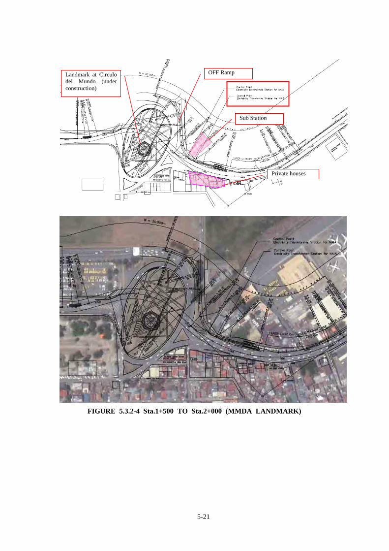
(1) Sta.1+500 to Sta.2+000 (MMDA Landmark) The alignment is selected to avoid traversing over the Landmark at Circulo del Mundo (under
construction). Existing Electrical Transformer Station for MIAA and private houses on the other side of the
road are considered as control points of the horizontal alignment design. These houses were already relocated before, so the Government of Pasay City strongly
requested to avoid affecting these houses. The off ramp to Terminal 3 (Andrew’s Avenue OFF Ramp) has also been designed without
affecting abovementioned facilities.
Parking of MIAA
Marriot Hotel
5-21
FIGURE 5.3.2-4 Sta.1+500 TO Sta.2+000 (MMDA LANDMARK)
Private houses
Sub Station
Landmark at Circulo del Mundo (under construction)
OFF Ramp

5-22
FIGURE 5.3.2-5 LANDMARK AT CIRCULO DEL MUNDO
FIGURE 5.3.2-6 PERSPECTIVE VIEW OF LANDMARK AND RECOMMENDED EXPRESSWAY ALIGNMENT

5-23
FIGURE 5.3.2-7 ELECTRICAL SUB-STATION FOR MIAA
(4) Sta.2+000 to Sta.2+800 The main alignment basically follows the existing at-grade road alignment (Andrews
Avenue). The main alignment is adjusted to avoid acquisition of land.
FIGURE 5.3.2-8 Sta.2+000 TO Sta.2+800

5-24
(5) Sta.2+800 to Sta.3+300 (LRT Depot) The previous FS alignment was designed along the existing road (R = 125m). Since the vertical alignment shall be an up-and-down grade in short distance due to
navigational clearance, the horizontal alignment is highly recommended to accommodate higher standard of geometry.
The alignment was reviewed to accommodate with larger (R = 190m) radius by using some LRTA property.
At the Domestic Road, the building of PAL DATA CENTER is considered as the control point (fronted at-grade road is critical).
This section needs to consider the navigational height limit of NAIA. Pump station in MIAA property is one of the control points for profile design and pier layout.
(Detail survey is necessary to identify associated facilities such as underground pipes for profile design and pier layout.)
Several private buildings and airport facilities need to be relocated.
FIGURE 5.3.2-9 Sta.2+800 to Sta.3+300 (LRT DEPOT)
(6) Sta.3+300 to Sta.3+950 (Domestic Road)
Due to NAIA navigational height limit, this section requires ROW acquisition to accommodate
6-lane at-grade road. In order to minimize the land acquisition, the outer shoulder of the expressway is reduced from
1.5m to 0.5m from Sta.3+300 to Sta.3+600. At-grade road was planned to maintain access to the abutting facility along the road.
LRTA property

5-25
PAL DATA CENTER, CEBU PACIFIC OPERATION CENTER and Salem Complex building are considered as control point to avoid demolition of large scale buildings.
The expressway alignment crosses post office land and vacant land owned by MIAA to avoid Park’n Fly building.
FIGURE 5.3.2-10 Sta.3+300 TO Sta.3+950 (DOMESTIC ROAD)

5-26
(7) Sta.3+950 to Sta.4+500 (Park ‘n Fly and Paranaque River)
The Park’n Fly Building and existing Paranaque River Bridge are set as control points for horizontal alignment design.
Since the expressway over the existing Paranaque river bridge will require 80m-long span bridge, the main alignment is designed to be tangent (or spiral curve) as much as possible.
FIGURE 5.3.2-11 Sta.3+950 TO Sta.4+500
(PARK ‘N FLY AND PARANAQUE RIVER)
(8) Sta.4+500 to Sta.4+913 (NIAA Road to Roxas Blvd)
The main alignment is selected to follow the existing median of at-grade road in order to maintain same existing number of lanes without land acquisition, even after completion of the expressway. (See Figure 5.3.2-13)
FIGURE 5.3.2-12 Sta.4+500 to Sta.4+913 (NAIA ROAD TO ROXAS BLVD)

5-27
FIGURE 5.3.2-13 CROSS SECTION OF NAIA ROAD
5.3.3 Vertical Alignment Study
1) Vertical Height Requirement by Structure Type for Vertical Alignment Planning For the planning of vertical alignment of the expressway, vertical height requirements by type of structure were studied as shown in Figure 5.3.3-1.
(2) Vertical Control Points
Vertical control points are shown in Table 5.3.3-1.
TABLE 5.3.3-1 VERTICAL CONTROL POINTS
Station Control Point Remark0+000 Beginning Point Maintain FS 20101+700 MMDA Monument2+384.5 Pedestrian Bridge EL=10.53(Floor level)2+550 Intersection with Aurora Blvd Intersection2+819.5 Navigational Clearance No.1 (see Table 5.3.3-2)2+938.4 Navigational Clearance No.2 (see Table 5.3.3-2)3+090 Intersection with Airport Road Intersection3+170 Intersection with Domestic Road Intersection3+092.8 Navigational Clearance No.3 (see Table 5.3.3-2)3+140 Navigational Clearance No.4 (see Table 5.3.3-2)3+330.8 Navigational Clearance No.5 (see Table 5.3.3-2)3+448.8 Navigational Clearance No.6 (see Table 5.3.3-2)4+450 Existing bridge of Paranaque River4+622 B-D Ramp of Roxas Interchange Pedestrian Overpass Bridge4+825 A-C ramp of Roxas Interchange Pedestrian Overpass Bridge

5-28
Type Name PC-1 Type Name PC-2Bridge Type Superstructure PC Girder Bridge Type Superstructure PC Girder Bridge Type Superstructure
Substructure Single Column Pier Substructure Multi Column Pier SubstructureStandard Type Standard Type at Curve Navigation Clearance
No Item Value Note No Item Value Note No Item Value Note1 Ground Level Varies 1 Ground Level Varies 1 Ground Level Varies2 Clearance(1) 5.00 2 Clearance(1) 5.00 2 Clearance(1)3 Coping Beam 3.00 3 Coping Beam 3.00 3 Coping Beam 0.004 Pavement 0.08 4 Pavement 0.08 4 Pavement 0.005 Bridge girder 1.60 5 Bridge girder 1.60 5 Bridge girder 0.006 Bridge slab 0.25 6 Bridge slab 0.25 6 Bridge slab 0.007 Cross Fall 0.60 10mx6%(max) 7 Cross Fall 0.60 10mx6%(max) 7 Cross Fall 0.00
8 Total 10.53 8 Total 10.53 8 Total
Type Name MT-1 Type Name MT-2 Type Name MT-3Bridge Type Superstructure Steel Box Girder Bridge Type Superstructure Steel Box Girder Bridge Type Superstructure Metal I Girder
Substructure Single Column Pier Substructure Multi Column Pier Substructure Metal Box PierStandard Type at Curve Standard Type at Curve Standard Type
No Item Value Note No Item Value Note No Item Value Note1 Ground Level Varies 1 Ground Level Varies 1 Ground Level Varies2 Clearance(1) 5.00 2 Clearance(1) 5.00 2 Clearance(1) 5.003 Coping Beam 2.50 3 Coping Beam 3.00 3 Coping Beam 0.754 Pavement 0.08 4 Pavement 0.08 4 Pavement 0.085 Bridge girder 2.50 5 Bridge girder 2.50 5 Bridge girder 0.006 Bridge slab 0.25 6 Bridge slab 0.25 6 Bridge slab 0.257 Cross Fall 0.60 10mx6%(max) 7 Cross Fall 0.60 10mx6%(max) 7 Cross Fall 0.00
8 Total 10.93 8 Total 11.43 8 Total 6.08
FIGURE 5.3.3-1 VERTICAL HEIGHT REQUIREMENT

5-29
(3) Vertical Clearance Verification against NAIA Navigational Height Limit The NAIA navigational height limit is calculated at six (6) points at the center of the road as shown in Figure 5.3.3-2. The vertical clearance is planned to be 5.0m for each of the expressway and the at-grade road. Clearance is verified at the road center elevation as shown in Table 5.3.3-2.
TABLE 5.3.3-2 VERIFICATION OF NAVIGATIONAL HEIGHT LIMIT
No StaDistance from Runway End
(m)
Slope I (2%)
Height Requirement from end of
Runway
GL of Runway (m)
Height Limit
Elevation from Mean
Elevation of Expressway
(m)
Vertical Clearance
for At-grade Road (m)
Remaining Net
Clearance (m)
1 2+819.5 580.9961456 0.02 11.620 3.000 14.620 8.818 5.00 0.802 2+938.4 659.8962553 0.02 13.198 3.000 16.198 9.658 5.00 1.543 3+092.8 666.4735739 0.02 13.329 3.000 16.329 10.866 5.00 0.464 3+140 644.1480343 0.02 12.883 3.000 15.883 10.772 5.00 0.115 3+330.8 489.7937027 0.02 9.796 3.000 12.796 7.684 5.00 0.116 3+448.8 387.1335765 0.02 7.743 3.000 10.743 5.466 5.00 0.28

5-30
FIGURE 5.3.3-2 NAVIGATIONAL CLEARANCE VERIFIED POINTS
(d) Main Alignment Profile
Figure 5.3.3-3 illustrates the type of bridges along NAIA Expressway 2 used for planning of profile. Profile of the main expressway is shown in the Drawing Volume.

5-31
FIGURE 5.3.3-3 TYPE OF BRIDGE FOR MAIN ALIGNMENT

5-32
5.3.4 Preliminary Design of Ramp Terminal
(a) Ramp layout Ramp layout of NAIA Expressway Phase II is shown in Figure 5.3.4-1.
FIGURE 5.3.4-1 SCHEMATIC NAIAX RAMP LAYOUT
(b) Design Approach Ramp terminal is designed to provide smooth, safe flow of the ingress and egress traffic on the expressway. On the other hand the design considered to minimize the land acquisition where the ramp terminal will be constructed. The major design approach is described hereafter.
1) Ramp Terminal Type In order to minimize land acquisition area and considering that all expressway sections are elevated structure, parallel type is chosen for ramp terminal design. The minimum length required for acceleration and deceleration lane is shown in Chapter _._ (see Table _._._-_).

5-33
TABLE 5.3.4-1 RAMP TERMINAL TYPE Terminal Type Taper Type Parallel Type
Schematic Image
Remark Applied in the design
2) Geometry of main alignment at ramp terminal
The ramp terminal should be easily recognized by drivers from sufficiently away from the ramp terminal and should provide smooth and safe flow of ramp traffic. In this context, geometric condition of the main alignment at ramp terminal is important. Table 5.3.4-2 shows the recommended geometry at ramp terminal by Japan Road Association, Road Structure Ordinance, 2004.
TABLE 5.3.4-2 RECOMMENDED MAIN ALIGNMENT GEOMETRY AT RAMP TERMINAL (V = 60KMH)
Recommended Absolute Value
Horizontal Curve Radius 500m 350m
Vertical Gradient 4.50% 5.50%
Minimum VCL(at crest) 6,000 3,000
(at sag) 4,000 2,000
However, the main alignment of the expressway is greatly restricted by the available ROW. The ramp terminal is located at the curve less than R = 300m. Basically, consideration of safe traffic flow of ramp terminal is very important in this respect. On the other hand it is not economical and practical to fully set the main alignment by this recommendation. Therefore, to install marginal length between end of sharp curve and beginning of speed change lane is considered to design the ramp terminal in order to provide safe and smooth traffic flow.
FIGURE 5.3.4-2 RAMP TERMINAL SPEED CHANGE LANE DESIGN

5-34
(c) Andrews Avenue ON Ramp (1) (to Skyway)
Andrews Avenue ON Ramp (1) is to provide access to the expressway for the traffic from Andrews Avenue and Terminal 3 (Arrival and Departure) to Skyway. The ramp alignment is set to avoid MIAA property (fence is considered as the control point). For connecting main alignment, the ramp acceleration lane requires air force property (approximately 4m in width). Toll gate equipped with three (3) toll booths is designed at grade road level. Vertical clearance of 5.0m is considered under the ramp bridge for the air force access road.
FIGURE 5.3.4-3 ANDREWS AVENUE ON RAMP (1)
Fence (MIAA)
Air Force Property
5-35
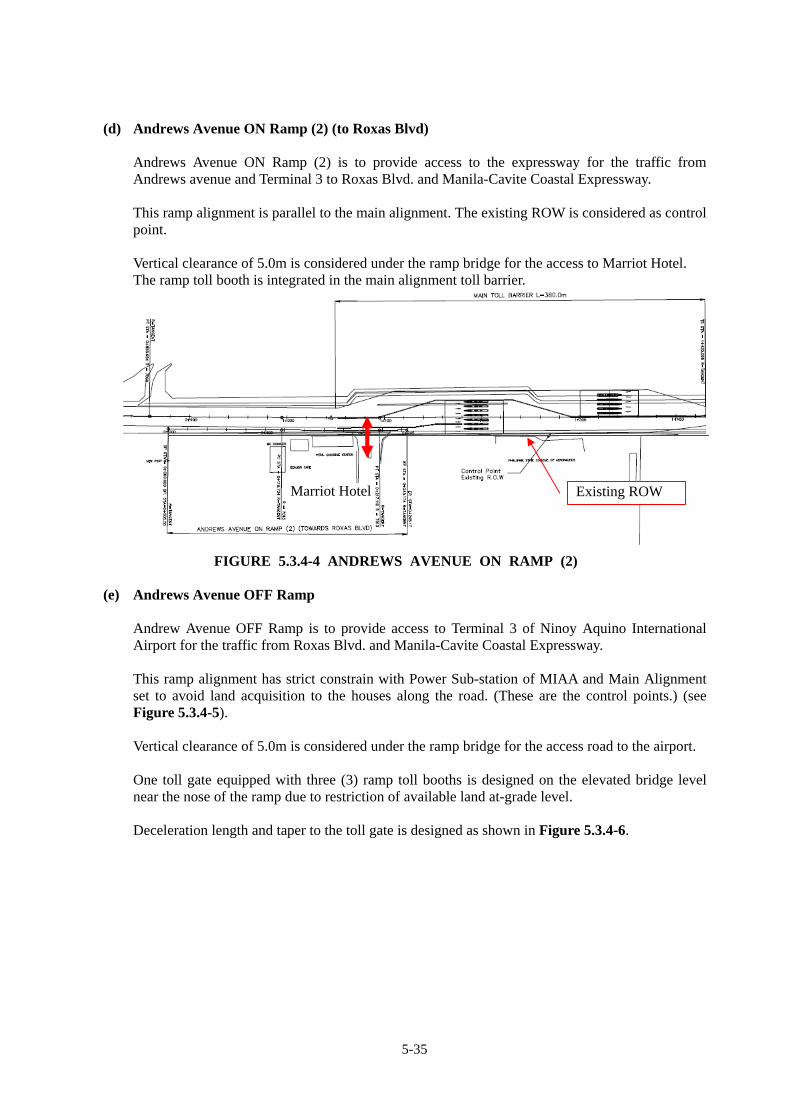
(d) Andrews Avenue ON Ramp (2) (to Roxas Blvd) Andrews Avenue ON Ramp (2) is to provide access to the expressway for the traffic from Andrews avenue and Terminal 3 to Roxas Blvd. and Manila-Cavite Coastal Expressway. This ramp alignment is parallel to the main alignment. The existing ROW is considered as control point. Vertical clearance of 5.0m is considered under the ramp bridge for the access to Marriot Hotel. The ramp toll booth is integrated in the main alignment toll barrier.
FIGURE 5.3.4-4 ANDREWS AVENUE ON RAMP (2)
(e) Andrews Avenue OFF Ramp
Andrew Avenue OFF Ramp is to provide access to Terminal 3 of Ninoy Aquino International Airport for the traffic from Roxas Blvd. and Manila-Cavite Coastal Expressway. This ramp alignment has strict constrain with Power Sub-station of MIAA and Main Alignment set to avoid land acquisition to the houses along the road. (These are the control points.) (see Figure 5.3.4-5). Vertical clearance of 5.0m is considered under the ramp bridge for the access road to the airport. One toll gate equipped with three (3) ramp toll booths is designed on the elevated bridge level near the nose of the ramp due to restriction of available land at-grade level. Deceleration length and taper to the toll gate is designed as shown in Figure 5.3.4-6.
Existing ROW Marriot Hotel

5-36
FIGURE 5.3.4-6 ANDREWS AVENUE OFF RAMP LANE LAYOUT

5-37
FIGURE 5.3.4-5 ANDREWS AVENUE OFF RAMP
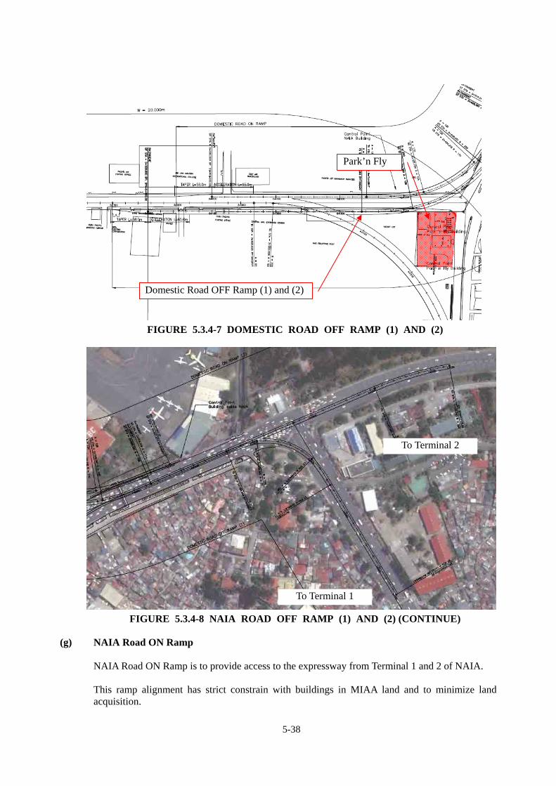
(f) Domestic Road OFF Ramp (1)and (2) (to Terminal 1 and 2) Domestic Road OFF Ramp is to provide access to Terminal 1 and 2 of NAIA for the traffic from Skyway (and Andrews Avenue).
This ramp alignment has strict constrain with Park’n Fly Building and to minimize land acquisition. The ramp alignment flyovers the main alignment and vertical clearance of 5.0m is considered between them.
The alignment of ramp is set in the median of existing at-grade road.
To Terminal 3
Sub Station of MIAA
Houses already relocated (Requested highest consideration)
Access Road to airport
5-38
FIGURE 5.3.4-7 DOMESTIC ROAD OFF RAMP (1) AND (2)
FIGURE 5.3.4-8 NAIA ROAD OFF RAMP (1) AND (2) (CONTINUE)
(g) NAIA Road ON Ramp
NAIA Road ON Ramp is to provide access to the expressway from Terminal 1 and 2 of NAIA. This ramp alignment has strict constrain with buildings in MIAA land and to minimize land acquisition.
Park’n Fly
Domestic Road OFF Ramp (1) and (2)
To Terminal 1
To Terminal 2
5-39
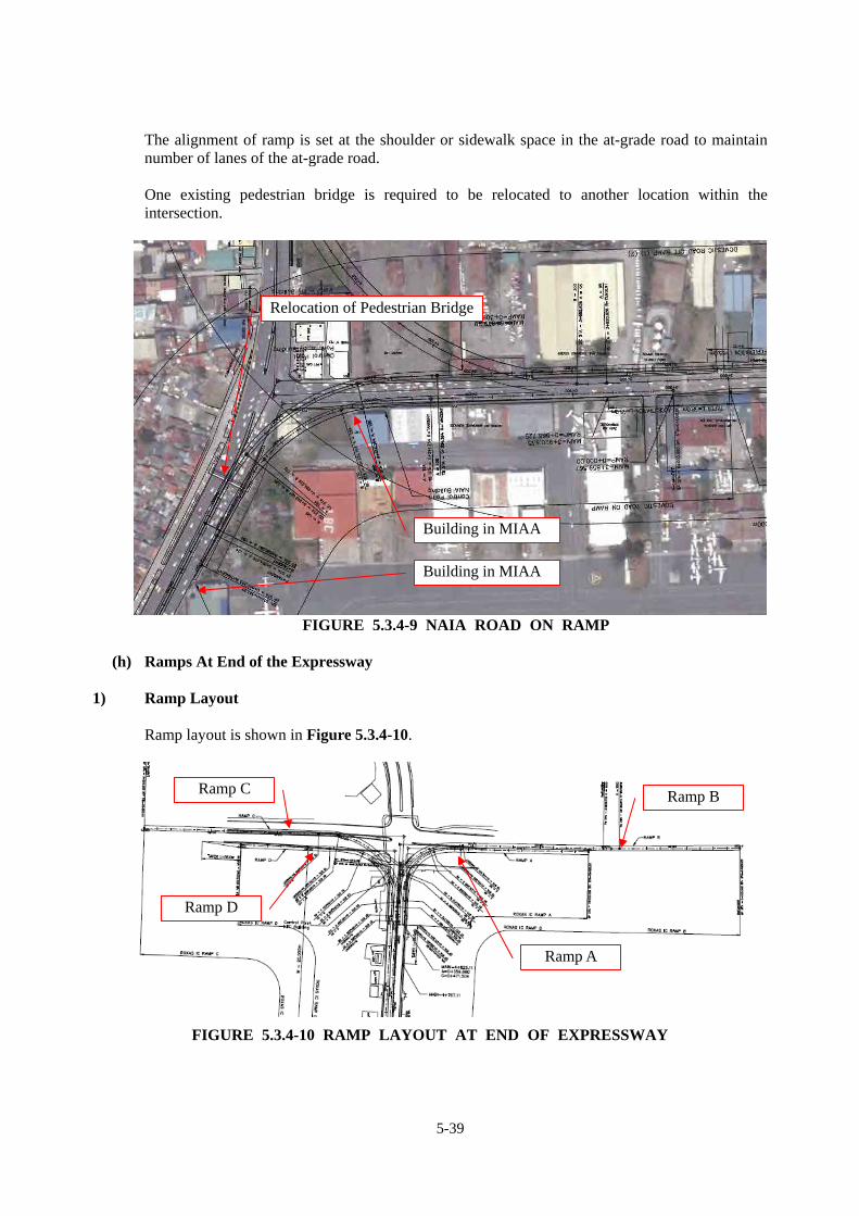
The alignment of ramp is set at the shoulder or sidewalk space in the at-grade road to maintain number of lanes of the at-grade road.
One existing pedestrian bridge is required to be relocated to another location within the intersection.
FIGURE 5.3.4-9 NAIA ROAD ON RAMP
(h) Ramps At End of the Expressway
1) Ramp Layout
Ramp layout is shown in Figure 5.3.4-10.
FIGURE 5.3.4-10 RAMP LAYOUT AT END OF EXPRESSWAY
Building in MIAA
Building in MIAA
Relocation of Pedestrian Bridge
Ramp A
Ramp B Ramp C
Ramp D
5-40
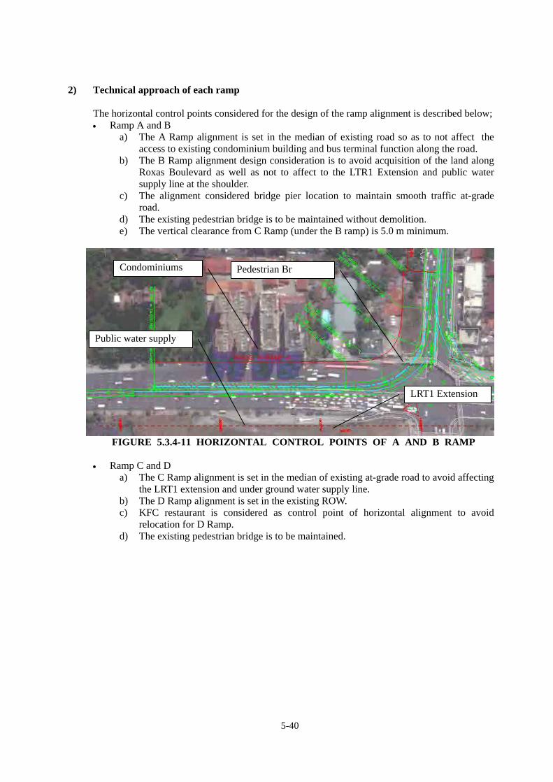
2) Technical approach of each ramp
The horizontal control points considered for the design of the ramp alignment is described below; Ramp A and B
a) The A Ramp alignment is set in the median of existing road so as to not affect the access to existing condominium building and bus terminal function along the road.
b) The B Ramp alignment design consideration is to avoid acquisition of the land along Roxas Boulevard as well as not to affect to the LTR1 Extension and public water supply line at the shoulder.
c) The alignment considered bridge pier location to maintain smooth traffic at-grade road.
d) The existing pedestrian bridge is to be maintained without demolition. e) The vertical clearance from C Ramp (under the B ramp) is 5.0 m minimum.
FIGURE 5.3.4-11 HORIZONTAL CONTROL POINTS OF A AND B RAMP
Ramp C and D
a) The C Ramp alignment is set in the median of existing at-grade road to avoid affecting the LRT1 extension and under ground water supply line.
b) The D Ramp alignment is set in the existing ROW. c) KFC restaurant is considered as control point of horizontal alignment to avoid
relocation for D Ramp. d) The existing pedestrian bridge is to be maintained.
Condominiums
Public water supply
LRT1 Extension
Pedestrian Br

5-41
FIGURE 5.3.4-12 HORIZONTAL CONTROL POINTS OF C AND D RAMP
3) Ramp terminal cross sectional configuration
Ramp terminal cross sectional configuration is shown in Figure 5.3.4-13. Accordingly diverge taper is calculated as below; Taper [email protected]/s lateral shift (V=60km/s) w=3.5m L=3.5x16.67 (m/s)=58.3 m 58.0m
Water supply under ground pipe
KFC
Existing ROW
Pedestrian Br

5-42
FIGURE 5.3.4-13 RAMP TERMINAL CROSS SECTIONAL CONFIGURATION

5-43
5.3.5 Preliminary Design of At-Grade Roads
(a) Number of traffic lanes to be maintained after construction At least the same number of traffic lanes of at-grade road shall be maintained even after the construction of expressway. The carriageway width may be reduced to a minimum 3.0 m.
TABLE 5.3.5-1 NUMBER OF LANES TO BE MAINTAINED Before construction After construction
Sales Avenue 2 + 3 = 5 3 + 3 = 6 Andrews Avenue 3 + 3 = 6 3 + 3 = 6 Domestic Road 3 + 3 = 6 3 + 3 = 6 NAIA Road (at Paranaque Bridge)
4 + 4 = 8 4 + 4 = 8
NAIA Road (Bridge to Roxas Blvd)
3 + 4 = 7 3 + 4 = 7
The typical cross section is shown in Section _._.
(b) Preliminary Design of At-Grade Road
Preliminary design of Andrews Avenue, Domestic Road and Roxas Boulevard is shown in Figure 5.3.5-1 to Figure 5.3.5-4

5-44
FIGURE 5.3.5-1 AT-GRADE ROAD PLAN (ANDREWS AVENUE)

5-45
FIGURE 5.3.5-2 AT-GRADE ROAD PLAN (ANDREWS AVENUE NEAR MMDA LANDMARK)

5-46
FIGURE 5.3.5-3 AT-GRADE ROAD PLAN (DOMESTIC ROAD)

5-47
FIGURE 5.3.5-4 AT-GRADE ROAD PLAN (ROXAS BOULEVARD-1)

5-48
FIGURE 5.3.5-4 AT-GRADE ROAD PLAN (ROXAS BOULEVARD-2)
5-49
5.4 STRUCTURE TYPE STUDY
5.4.1 General
The general features of these structures are as follows:
1) AASHTO Girder
As the standard bridge type, AASHTO Girder – pre-stressed concrete I-section girder was
adopted, because it is the most economical and widely used in the Philippines (many suppliers
and local productions exist in the Philippines). And the erection is not affecting to the underneath
traffic and consideration of transportation ease.
To apply the span ranged from 30 to 35 m length (pier center to center length) was determined by
the cost comparison.
2) Single Column with Cantilevered Pier Head
Single column with cantilevered pier head constructed by adopting the rotating method was
considered to minimize the working area and period.
3) Pile Foundation
According to the soil investigation result of the previous study (feasibility study in Year 2010),
the assumed bearing strata exists 1.0m to 10.0m depth from the existing ground level. Although
spread footing type of foundation can be adoptable, pile foundation was selected in consideration
of traffic management during construction.
4) Pile Bent-up Type Pier
Single column type of with single large diameter pile pier for main expressway was not used in
this study. This type was only used for multi column piers and ramp piers. The type should be
determined by more detailed analysis and calculation with accurate data.
5) Steel Girder and Pier
Steel girder was adopted at long span section – 40m or longer, curved section and the height
limited section. For high piers with over 20m in height from ground level and those of complex
type, steel piers were adopted.
6) Bridge Approach
Mechanically Stabilized Earth Retaining Wall (MSE Wall) was adopted at the bridge approach,
since it could be constructed in narrow working space with reasonable cost, and good aesthetic.

5-50
5.4.2 Bridge Type at Individual Section
Based on the above consideration, bridge types were proposed. The types of bridges are shown in
Figure 5.4.2-1.
The individual features are described in Table 5.4.2-1 and 5.4.2-2, and the cross sections are
shown in Figure 5.4.2-2.

5-51
FIGURE 5.4.2-1 INDEX MAP FOR BRIDGE TYPE

5-52
TABLE 5.4.2-1 BRIDGE FEATURES AT EACH LOCATION TYPE No. Location Features Figure No.
(see Figure 5.4.2-2)
Main Carriageway 1 Sales Street - AASHTO girder type IV and multi column (2 column)
type with rectangular section pier was determined following to the piers of Phase-I,
- 3 lane carriageway per each bound underneath the viaduct were considered to arrange the column location.
1, 2
2 Sales St. – Andrew Ave.
Steel box girder in consideration of the curve configuration and concrete hammerhead & single column (circular section) type pier was adopted.
3
3 Andrew Avenue
- At general section: AASHTO girder type V and concrete hammerhead & single column (circular section) type pier was adopted,
- At toll barrier section: AASHTO girder type V and concrete multi column (3 column) type pier was adopted,
- At MMDA Monument section: it shall be followed the required long span and curve alignment, continuous steel box girder and concrete multi column type pier was mainly determined,
- At Aurora Boulevard intersection: to consider the future operation of the road, 50m span by steel box girder was determined,
- At limited navigation clearance section: Steel I-girder and steel pier (rigid frame type) was determined in consideration of the maximum superstructure depth of 1.0m.
4, 5, 6, 7, 8, 9, 10, 11, 12, 13, 14, 15, 16
4 Andrew Ave. – Domestic Rd.
- Steel box girder in consideration of the curve configuration and concrete hammerhead & single column (circular section) type pier was adopted.
17
5 Domestic Road - At limited navigation clearance section: Steel I-girder and steel pier (rigid frame type), and prestressed concrete hollow slab and concrete multi column (2 column) were determined to adopt,
- At Ramps to/from NAIA Terminal 1 & 2 transition section: AASHTO girder type V and concrete multi column type pier was adopted.
18, 19, 20, 21
6 Domestic Rd. – NAIA Rd.
- Steel box girder in consideration of the curve configuration and concrete hammerhead & single column (circular section) type pier was adopted.
22
7 NAIA Road - At Ramp transition section: AASHTO girder type V and concrete multi column type pier was adopted.
23, 24

5-53
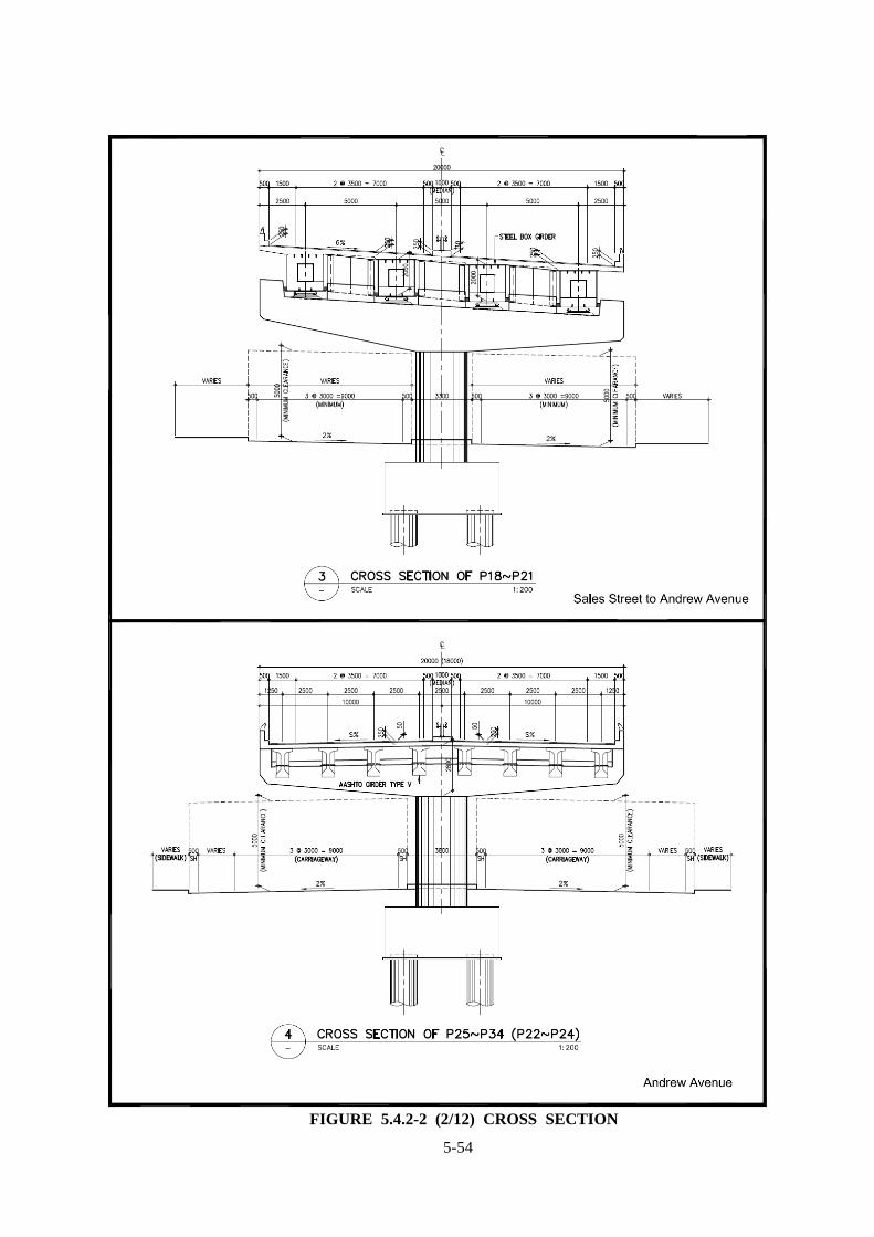
FIGURE 5.4.2-2 (1/12) CROSS SECTION
5-54
FIGURE 5.4.2-2 (2/12) CROSS SECTION

5-55
FIGURE 5.4.2-2 (3/12) CROSS SECTION

5-56
FIGURE 5.4.2-2 (4/12) CROSS SECTION

5-57
FIGURE 5.4.2-2 (5/12) CROSS SECTION

5-58
FIGURE 5.4.2-2 (6/12) CROSS SECTION

5-59
FIGURE 5.4.2-2 (7/12) CROSS SECTION

5-60
FIGURE 5.4.2-2 (8/12) CROSS SECTION

5-61
FIGURE 5.4.2-2 (9/12) CROSS SECTION

5-62
FIGURE 5.4.2-2 (10/12) CROSS SECTION

5-63
FIGURE 5.4.2-2 (11/12) CROSS SECTION

5-64
FIGURE 5.4.2-2 (12/12) CROSS SECTION

5-65
TABLE 5.4.2-2 BRIDGE TYPE: RAMP No. Location Features Figure No.
(see Figure 5.4.2-2)
Main Carriageway 1 Sales Street - AASHTO girder type IV and multi column (2 column)
type with rectangular section pier was determined following to the piers of Phase-I,
- 3 lane carriageway per each bound underneath the viaduct were considered to arrange the column location.
1, 2
2 Sales St. – Andrew Ave.
Steel box girder in consideration of the curve configuration and concrete hammerhead & single column (circular section) type pier was adopted.
3
3 Andrew Avenue
- At general section: AASHTO girder type V and concrete hammerhead & single column (circular section) type pier was adopted,
- At toll barrier section: AASHTO girder type V and concrete multi column (3 column) type pier was adopted,
- At MMDA Monument section: it shall be followed the required long span and curve alignment, continuous steel box girder and concrete multi column type pier was mainly determined,
- At Aurora Boulevard intersection: to consider the future operation of the road, 50m span by steel box girder was determined,
- At limited navigation clearance section: Steel I-girder and steel pier (rigid frame type) was determined in consideration of the maximum superstructure depth of 1.0m.
4, 5, 6, 7, 8, 9, 10, 11, 12, 13, 14, 15, 16
4 Andrew Ave. – Domestic Rd.
- Steel box girder in consideration of the curve configuration and concrete hammerhead & single column (circular section) type pier was adopted.
17
5 Domestic Road - At limited navigation clearance section: Steel I-girder and steel pier (rigid frame type), and prestressed concrete hollow slab and concrete multi column (2 column) were determined to adopt,
- At Ramps to/from NAIA Terminal 1 & 2 transition section: AASHTO girder type V and concrete multi column type pier was adopted.
18, 19, 20, 21
6 Domestic Rd. – NAIA Rd.
- Steel box girder in consideration of the curve configuration and concrete hammerhead & single column (circular section) type pier was adopted.
22
7 NAIA Road - At Ramp transition section: AASHTO girder type V and concrete multi column type pier was adopted.
23, 24

5-66
FIGURE 5.4.2-3 (1/4) RAMP CROSS SECTION

5-67
FIGURE 5.4.2-3 (2/4) RAMP CROSS SECTION

5-68
FIGURE 5.4.2-3 (3/4) RAMP CROSS SECTION

5-69
FIGURE 5.4.2-3 (4/4) CROSS SECTION
5-70
5.5 PRELIMINARY DESIGN OF PAVEMENT STRUCTURE
The pavement design includes restoration of pavement structures affected by construction of expressway foundation and drainage.
The existing at-grade road pavement (PCCP with AC overlay) affected will be replaced by the same pavement structure.
For the elevated structure, 8 cm thickness of the AC pavement is considered on the concrete slab.
5.6 PRELIMINARY DESIGN OF DRAINAGE
Basic concept to drainage design is shown below; 1. The drainage design shall be carried out to collect water efficiently and discharge it without
aggravating present flood situation. 2. The water flow in accordance with runoff of bridge surface and collect at the drop in let
normally installed every column. 3. From downspout end the collected water shall be discharged to the existing drainage line at
the side of the road. 4. In case, the existing drainage is not effecting or insufficient capacity, a new line or
improvement of the drainage line shall be considered.
5.7 TOLL BARRIER AND TOLL BOOTH
5.7.1 Toll Booth Layout
The number of toll booth of each ramp terminal is shown in Table 5.7.1-1.
TABLE 5.7.1-1 NUMBER OF TOLL BOOTH
No Ramp name Number of Toll Booth
1 Andrews Avenue On Ramp(1) 3
2 Andrews Avenue OFF Ramp 3
3 Toll gate from Skyway 7
4 Toll gate from Roxas 5
5 Andrews Avenue OFF Ramp(existing) 3
One toll gate booth is composed of one (1) maxi-booth equipped with toilet. The size is set by referring to the Phase I toll gate. (Figure 5.7.1-1)
Concrete pavement is designed at the length of 25m for each approach and departure zone side.
Minimum interval of each booth is 3.0m for passenger car carriage way.
Minimum interval for truck is 3.5m.
The vertical grade at toll gate is recommended less than 2.0% and absolute value is 3.0%(Highway design manual, NEXCO, Japan) for the minimum length of 50m. The vertical curve radius is recommended more than 700m at the toll gate. This standard has been considered, however, due to restriction of R.O.W and at-grade road condition, some elements of this requirement may not be accommodated.
5-71
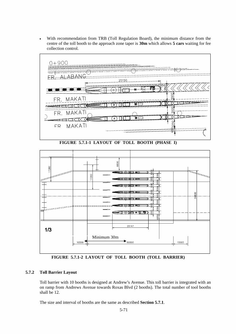
With recommendation from TRB (Toll Regulation Board), the minimum distance from the centre of the toll booth to the approach zone taper is 30m which allows 5 cars waiting for fee collection control.
FIGURE 5.7.1-1 LAYOUT OF TOLL BOOTH (PHASE I)
FIGURE 5.7.1-2 LAYOUT OF TOLL BOOTH (TOLL BARRIER)
5.7.2 Toll Barrier Layout
Toll barrier with 10 booths is designed at Andrew’s Avenue. This toll barrier is integrated with an on ramp from Andrews Avenue towards Roxas Blvd (2 booths). The total number of tool booths shall be 12. The size and interval of booths are the same as described Section 5.7.1.
Minimum 30m

5-72
Taper of the approach and the departure zone is designed with a 1:3 tangent slope.
FIGURE 5.7.2-1 LAYOUT OF TOLL BARRIER
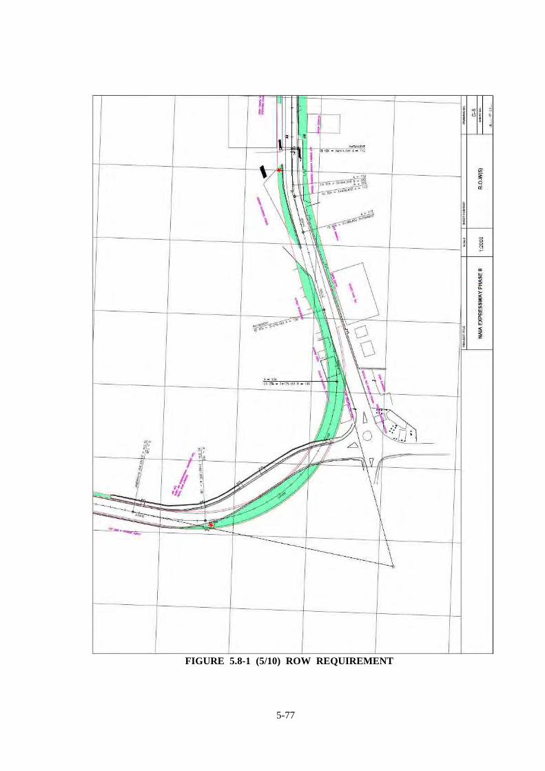
5.8 ROW REQUIREMENT BASED ON PRELIMINARY DESIGN ROW requirement based on the preliminary design is shown in Figure 5.8-1.

5-73
FIGURE 5.8-1 (1/10) ROW REQUIREMENT

5-74
FIGURE 5.8-1 (2/10) ROW REQUIREMENT

5-75
FIGURE 5.8-1 (3/10) ROW REQUIREMENT

5-76
FIGURE 5.8-1 (4/10) ROW REQUIREMENT
5-77
FIGURE 5.8-1 (5/10) ROW REQUIREMENT

5-78
FIGURE 5.8-1 (6/10) ROW REQUIREMENT

5-79
FIGURE 5.8-1 (7/10) ROW REQUIREMENT

5-80
FIGURE 5.8-1 (8/10) ROW REQUIREMENT

5-81
FIGURE 5.8-1 (9/10) ROW REQUIREMENT

5-82
FIGURE 5.8-1 (10/10) ROW REQUIREMENT

5-83
5.9 RISKS Risks allocation matrix and how these risks are incorporated in the Draft Toll Concession
Agreement are summarized in Table 5.9-1.

TABLE 5.9-1 RISK ALLOCATION MATRIX
Note: Section numbers refer to those in the Draft Concession Agreement. Nature of Risk Government (DPWH) Private Sector (Concessionaire)
Financial risks *Government counterpart financing. DPWH is responsible and bears the risks for financing the following counterpart costs: (a) cost of the Basic Right-of-Way (ROW), (b) Government Financial Support (GFS) for Construction, (c) ½ of the fee of the Project Consultant (PC), and (d) expenses for DPWH technical supervision of the Project. (Sec. 5.0, 9.4 and 9.5). Major risks: Understated Basic ROW prices. Failure to provide adequate GFS on time – Ground for
Default and Termination Extraordinary inflation and forex fluctuation.
*Project financing. The Concessionaire is responsible and bears the risk for Financing of the Project, covering the cost of DED, Construction, O&M, and Additional ROW - net of the Government counterpart financing (for the Basic ROW, GFS, ½ of fee of IC, and technical supervision expenses). (Sec. 6.(a)). Major risks; Overrun in costs of DED, Construction, and Additional ROW. Extraordinary inflation and forex fluctuation. *Financing Agreements. The Concessionaire may enter into agreements with Financiers/ Lenders for the Financing of the Project as it may deem desirable or necessary (Sec. 9.2). Major risks: Delay in meeting Financiers’ pre-requisites. *Financial closure. The Concessionaire shall achieve financial closure not later than 12 months after the signing of the Agreement, with the following evidence: (a) Concessionaire’s Shareholders Agreement and receipt of payment of shareholders (equity), (b) Project Financing Agreements with Financiers/ Lenders (Sec. 9.3). Major risk: Failure to submit complete Shareholders Agreements and financing
Agreements as evidence of Financial Closure within the 12-month period –Ground for Default and Termination.
ROW risks *Responsibility for Basic ROW. DPWH is responsible and bear the risks for the acquisition and delivery to the Concessionaire of the Basic ROW, clear of any liens and obstructions, not later than 6 months after the signing of the Agreement. This includes the relocation of informal settlers
* Responsibility for Additional ROW. The Concessionaire shall be responsible and bear the risks, at its sole cost, for the acquisition of Additional ROW which it needs, aside from the Basic ROW to be provided by DPWH (Sec. 11.2).
5-84

Nature of Risk Government (DPWH) Private Sector (Concessionaire)
and other occupants, removal/relocation of utilities, removal of obstacles, and settlement of third party claims (Sec. 5.0(b), 11.1 and 18.3).
Major risks: Non-delivery, incomplete delivery or late delivery of Basic
ROW – Ground for Default and Termination Resistance of informal settlers for removal and relocation. Uncertain conditions and costs of underground utilities to
be removed/relocated. Increased Basic ROW costs.
Major risks: Substantial area and cost of Additional ROW to be acquired. Delay in the acquisition of Additional ROW.
Design risks *Minimum Expressway Configuration. DPWH shall be responsible and bear the risks, including cost consequences, for any changes that it will introduce, after the bidding, in the Minimum Performance Standards and Specifications (MPSS) including the Minimum Expressway Configuration (Sec. 12.1(c)). Major risks: Changes, after bidding, in the Minimum Expressway
Configuration, e.g., alignment and location of (i) main expressway, (ii) roundabout/Circulo del Mundo, (iii) NAIA height limitation section, (iv) alignment at Domestic Rd/MIA Rd., (v) ramps.
Difficulties/delay in getting clearance/consultation from entities concerned – MMDA, MIAA, CAAP, LRTA, LGUs, general public.
Change in toll collection system from open to closed system.
*Approval/action on DED. DPWH shall approve/act on the Concessionaire’s Detailed Engineering Design (DED), certified by the PC, within 15 days after its submission (Sec. 5.0c, 12.2, and 18.3).
*Preparation and submission of DED. The Concessionaire is responsible and bear the risks for the preparation - by itself or its designated Designer – of the DED of the Project in accordance with the MPSS for Design, and for the submission of the DED to DPWH - certified by the PC - within 10 months after the signing of the Agreement (Sec. 6.0(e) and 18.2(a)). Major risks: Inadequate geotechnical and other engineering investigations. Requests of LGUs for additional/relocation of ramps/facilities. Over-design with resulting high construction cost. Under-design resulting in early deterioration, higher maintenance, and
lower level of service. Difficulty/delay in securing a new ECC if DED differs significantly from
the original configuration covered by existing ECC. Failure to submit compliant, PC-certified DED within the 10-month
period – Ground for Default and Termination. *Undiminished responsibility for DED integrity. DPWH’s approval of the DED shall not diminish the responsibility of the Concessionaire for the integrity of the DED, or transfer any part of such responsibility to DPWH (Sec. 12.2(d)).
5-85

Nature of Risk Government (DPWH) Private Sector (Concessionaire)
Major risks: Failure to approve/take action on the PC-certified DED on
time – Ground for Default and Termination. Changes in MPSS after submission of DED. DPWH-initiated changes in design, e.g., new/relocation of
ramps, realignment, after submission of DED.
Major risks: Design error, affecting the structural integrity. Delayed submission of compliant DED
Construction and completion risks
*Technical supervision. DPWH is responsible for technical supervision and monitoring of the Construction undertaken by the Concessionaire (Sec. 13.5). Major risks: Poor technical supervision by DPWH/IC. *DPWH-initiated variations. DPWH is responsible for extra costs and time extensions due to variations initiated by DPWH in the following cases: (a) changes in the MPSS for Design and Construction or the Scope of Construction, and (b) change in law such that the variation is necessary to ensure compliance (Sec. 13.6). Major risks: Significant DPWH-variations, e.g., resulting in
considerable extra costs, ROW, and implementation delays to be borne by DPWH.
*Certificate of Completion. DPWH shall issue the Certificate of Final Completion (CFC) within 7 days after the PC’s certification of Concessionaire’s compliance with the requirements and recommendation Sec. 13.8). Major risks: Delay in the issuance of the CFC despite Concessionaire’s
compliance with requirements as certified by the PC.
*Responsibility for Construction. The Concessionaire is responsible and bear the risks for the Construction of the Facility - by itself or its designated Contractor - in accordance with the Concessionaire’s DED as approved by DPWH, and in conformance with the MPSS for Construction, which shall be completed not later than 24 months after the Notice to Proceed to Construct (Sec. 6.0c, 13.0, and 18.2). Major risks: Slippage of 20% or more due to the Concessionaire’s fault – Ground for
Default and Termination.. Failure to remedy major defects/deviations from the approved DED
whose cost is 20% or more or the value of work within 6-month period - Ground for Default and Termination..
Failure to complete the Project satisfactorily and secure a CFC before the target completion date due to Concessionaire’s fault - Ground for Default and Termination.
Substandard quality of Construction. Confiscation of Performance Security for Construction because of
Concessionaire’s failure to fulfil its above obligations. Liquidated damages due to delayed completion beyond d target date. Cost overruns in Construction. Unexpected changes in geotechnical and other engineering conditions,
with consequent extra costs and delays. Concessionaire-initiated variations, resulting in extra costs, ROW and
delays to be assumed by the Concessionaire. Inadequate traffic management during Construction, resulting in
5-86

Nature of Risk Government (DPWH) Private Sector (Concessionaire)
.
congestion, accidents, and business slowdown. Unexpected heavy/prolonged rains, causing floods, jams and delays. *Responsibility for Contractors and sub-contractors. The Concessionaire shall assume full responsibility and accountability for the actions and quality of works of its Contractors and sub-contractors, which shall be in compliance with the MPSS and other provisions of the Agreement (Sec. 13.4(b)). Major risks: Substandard performance of Contractor and sub-contractors. *Construction permits and other approvals. The Concessionaire is responsible for securing all necessary Construction permits, licenses, authorization, and approvals from concerned national agencies and LGUs, and for assuming their attendant costs and fees, prior to the start of Construction activities (Sec. 13.4(c)). Major risks: Difficulties/delays in obtaining permits and other approvals. *Undiminished responsibility for Facility integrity and performance. DPWH’s issuance of the Certificate of Final Completion does not diminish the responsibility of the Concessionaire for the structural integrity and performance of the Facility during the Concession Period, or transfer any part of that responsibility to DPWH (Sec. 13.8(h)). Major risks: Structural failure due to faulty Construction. *Insurance. The Concessionaire shall secure insurance coverage during Construction against all insurable risks, including contractor’s all-risk insurance, force majeure, and third-party liability (Sec. 15.1(1)). Major risks:
5-87
Nature of Risk Government (DPWH) Private Sector (Concessionaire)
Failure to secure the required insurance coverage - Ground for Default and Termination.
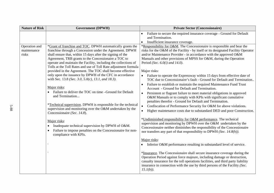
Insufficient insurance coverage. Operation and maintenance risks
*Grant of franchise and TOC. DPWH automatically grants the franchise through a Concession under the Agreement. DPWH shall ensure that, within 15 days after the signing of the Agreement, TRB grants to the Concessionaire a TOC to operate and maintain the Facility, including the collections of Tolls at the Toll Rates and use of Toll Rate adjustment formula provided in the Agreement. The TOC shall become effective only upon the issuance by DPWH of the CFC in accordance with Sec. 13.8 (Sec. 3.0, 5.0(c), 13.1, and 18.3). Major risks: Failure to deliver the TOC on time –Ground for Default
and Termination... *Technical supervision. DPWH is responsible for the technical supervision and monitoring over the O&M undertaken by the Concessionaire (Sec. 14.8). Major risks: Inadequate technical supervision by DPWH of O&M. Failure to impose penalties on the Concessionaire for non-
compliance with KPIs. . .
*Responsibility for O&M. The Concessionaire is responsible and bear the risks for the O&M of the Facility - by itself or its designated Facility Operator and/or Maintenance Provider - in accordance with the approved O&M Manuals and other provisions of MPSS for O&M, during the Operation Period (Sec. 6.0(i) and 14.0). Major risks: Failure to operate the Expressway within 15 days from effective date of
TOC due to Concessionaire’s fault - Ground for Default and Termination.. Failure to establish or maintain the required Maintenance Fund Trust
Account - Ground for Default and Termination. Persistent or flagrant failure to meet material obligations in approved
O&M Manuals or to comply with KPIs with significant cumulative penalties therefor - Ground for Default and Termination.
Confiscation of Performance Security for O&M for above violations. Higher maintenance costs due to substandard DED and poor Construction. *Undiminished responsibility for O&M performance. The technical supervision and monitoring by DPWH over the O&M undertaken by the Concessionaire neither diminishes the responsibility of the Concessionaire nor transfers any part of that responsibility to DPWH (Sec. 14.8(h)). Major risks: Inferior O&M performance resulting in substandard level of service. *Insurance. The Concessionaire shall secure insurance coverage during the Operation Period against force majeure, including damage or destruction, casualty insurance for the toll operations facilities, and third party liability insurance in connection with the use by third persons of the Facility (Sec. 15.1(b)).
5-88
Nature of Risk Government (DPWH) Private Sector (Concessionaire)
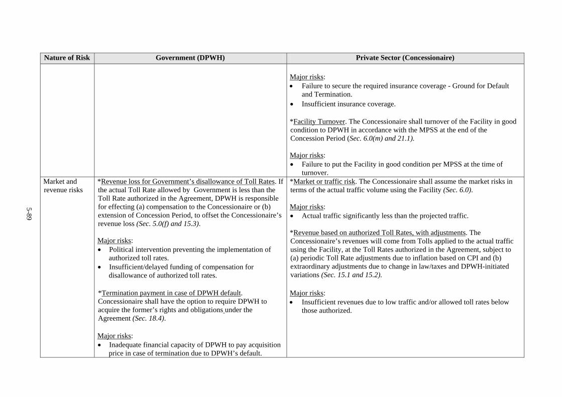
Major risks: Failure to secure the required insurance coverage - Ground for Default
and Termination. Insufficient insurance coverage. *Facility Turnover. The Concessionaire shall turnover of the Facility in good condition to DPWH in accordance with the MPSS at the end of the Concession Period (Sec. 6.0(m) and 21.1). Major risks: Failure to put the Facility in good condition per MPSS at the time of
turnover. Market and revenue risks
*Revenue loss for Government’s disallowance of Toll Rates. If the actual Toll Rate allowed by Government is less than the Toll Rate authorized in the Agreement, DPWH is responsible for effecting (a) compensation to the Concessionaire or (b) extension of Concession Period, to offset the Concessionaire’s revenue loss (Sec. 5.0(f) and 15.3). Major risks: Political intervention preventing the implementation of
authorized toll rates. Insufficient/delayed funding of compensation for
disallowance of authorized toll rates. *Termination payment in case of DPWH default. Concessionaire shall have the option to require DPWH to acquire the former’s rights and obligations under the Agreement (Sec. 18.4). Major risks: Inadequate financial capacity of DPWH to pay acquisition
price in case of termination due to DPWH’s default.
*Market or traffic risk. The Concessionaire shall assume the market risks in terms of the actual traffic volume using the Facility (Sec. 6.0). Major risks: Actual traffic significantly less than the projected traffic. *Revenue based on authorized Toll Rates, with adjustments. The Concessionaire’s revenues will come from Tolls applied to the actual traffic using the Facility, at the Toll Rates authorized in the Agreement, subject to (a) periodic Toll Rate adjustments due to inflation based on CPI and (b) extraordinary adjustments due to change in law/taxes and DPWH-initiated variations (Sec. 15.1 and 15.2). Major risks: Insufficient revenues due to low traffic and/or allowed toll rates below
those authorized.
5-89
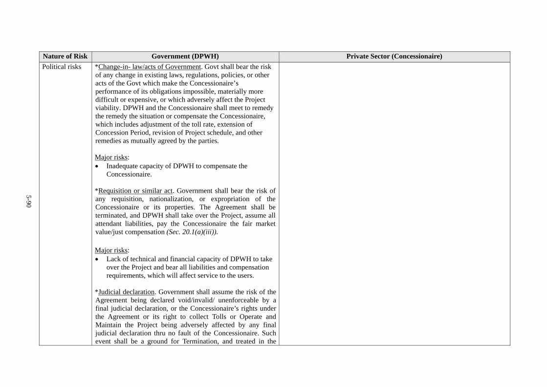
Nature of Risk Government (DPWH) Private Sector (Concessionaire)
Political risks *Change-in- law/acts of Government. Govt shall bear the risk of any change in existing laws, regulations, policies, or other acts of the Govt which make the Concessionaire’s performance of its obligations impossible, materially more difficult or expensive, or which adversely affect the Project viability. DPWH and the Concessionaire shall meet to remedy the remedy the situation or compensate the Concessionaire, which includes adjustment of the toll rate, extension of Concession Period, revision of Project schedule, and other remedies as mutually agreed by the parties. Major risks: Inadequate capacity of DPWH to compensate the
Concessionaire. *Requisition or similar act. Government shall bear the risk of any requisition, nationalization, or expropriation of the Concessionaire or its properties. The Agreement shall be terminated, and DPWH shall take over the Project, assume all attendant liabilities, pay the Concessionaire the fair market value/just compensation (Sec. 20.1(a)(iii)).
Major risks: Lack of technical and financial capacity of DPWH to take
over the Project and bear all liabilities and compensation requirements, which will affect service to the users.
*Judicial declaration. Government shall assume the risk of the Agreement being declared void/invalid/ unenforceable by a final judicial declaration, or the Concessionaire’s rights under the Agreement or its right to collect Tolls or Operate and Maintain the Project being adversely affected by any final judicial declaration thru no fault of the Concessionaire. Such event shall be a ground for Termination, and treated in the
5-90

Nature of Risk Government (DPWH) Private Sector (Concessionaire)
same manner as a requisition (Sec. 20.1(a)(iii)).
Major risks: Insufficient technical and financial capacity of DPWH to
take over the Project and assume all liabilities and compensation requirements, which will affect service to the users.
Force majeure risks
*Excuse from performance. For force majeure events, DPWH shall be excused from performing its obligations under the Agreement, but shall not be released from its monetary obligations (Sec. 20.1(b)). Major risks: Inadequate DPWH capacity to meet its monetary
obligations in case of force majeure. *Responsibility for repair or reconstruction. If the Concessionaire is unable to raise funds for any required reconstruction and/or repair work on the damaged Toll Facility, DPWH shall undertake such reconstruction and/or repair work in order to reinstate the damaged Facility (Sec. 20.3). Major risks: Inadequate funding to undertake the repair work.
* Excuse from performance. For force majeure events, the Concessionaire shall be excused from performing its obligations under the Agreement, but shall not be released from its monetary obligations (Sec. 20.1(b)). Major risks: Inadequate Concessionaire’s capacity to meet its monetary obligations in
case of force majeure. *Funding of repair or reconstruction. The Concessionaire is responsible for taking actions to mitigate any damage by utilizing any insurance proceeds covering force majeure. If the Concessionaire is unable to perform the required reconstruction or repair due to insufficient insurance proceeds, the Concessionaire has the option to provide any funding shortfall, and/or undertake the reconstruction/repair work. Any amount advanced/incurred by the Concessionaire in this regard shall be repaid by an appropriate extraordinary Adjustment in the Toll Rates, or extension of the Concession Period, or direct payment, or other means as mutually agreed by the parties (Sec. 20.3). Major risks: Inadequate insurance proceeds and Concessionaire’s funds for the repair
work.
5-91