Embed Size (px)
Citation preview

Engr228 - Chapter 5, Hayt 8E 1
Chapter 5
Engr228
Circuit Analysis
Dr Curtis Nelson
Chapter 5 Objectives
• State and apply the property of linearity
• State and apply the property of superposition
• Investigate source transformations
• Define and construct Thevenin and Norton equivalent
circuits
• Investigate maximum power transfer to a load
Engr228 - Chapter 5, Hayt 8E 2
Linear Elements and Circuits
• A linear circuit element has a linear voltage-current
relationship:
– If i(t) produces v(t), then Ki(t) produces Kv(t)
– If i1(t) produces v1(t) and i2(t) produces v2(t), then i1(t) + i2(t) produces
v1(t) + v2(t),
• Resistors and sources are linear elements
– Dependent sources need linear control equations to be linear elements
• A linear circuit is one with only linear elements
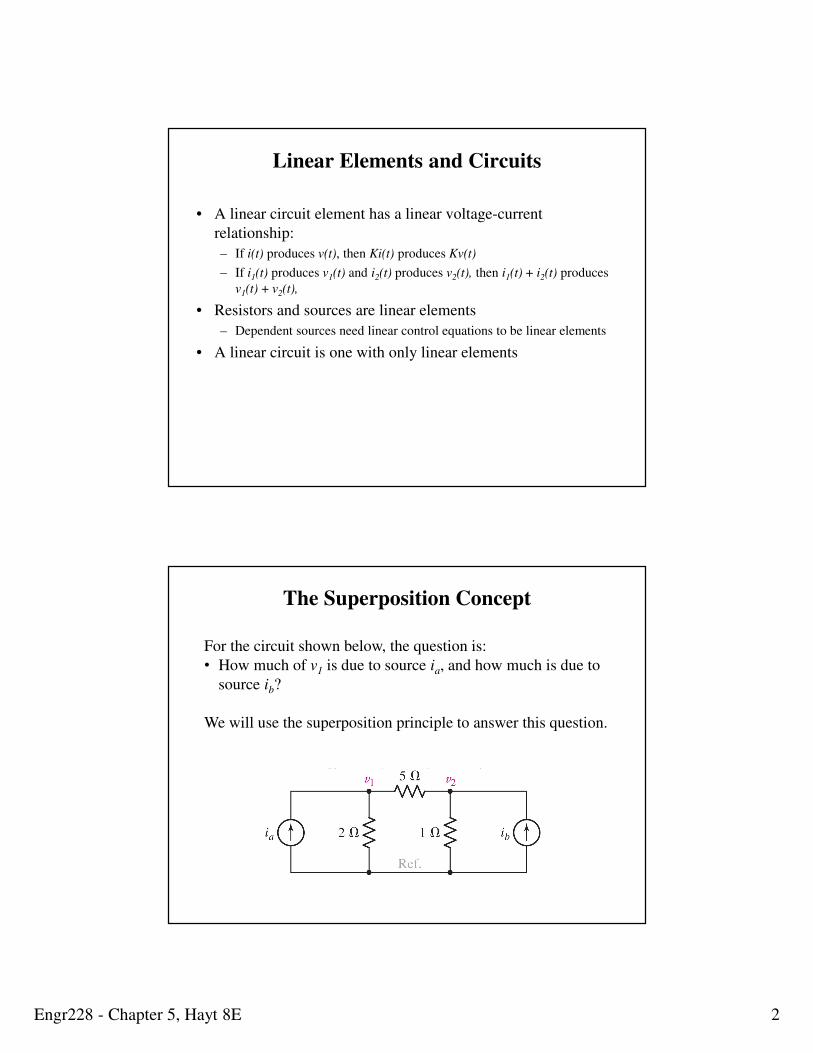
The Superposition Concept
For the circuit shown below, the question is:
• How much of v1 is due to source ia, and how much is due to
source ib?
We will use the superposition principle to answer this question.
Engr228 - Chapter 5, Hayt 8E 3
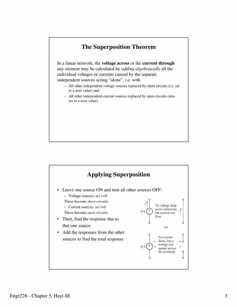
The Superposition Theorem
In a linear network, the voltage across or the current through
any element may be calculated by adding algebraically all the
individual voltages or currents caused by the separate
independent sources acting “alone”, i.e. with
– All other independent voltage sources replaced by short circuits (i.e. set
to a zero value) and
– All other independent current sources replaced by open circuits (also
set to a zero value).
Applying Superposition
• Leave one source ON and turn all other sources OFF:
– Voltage sources: set v=0
These become short circuits.
– Current sources: set i=0
These become open circuits.
• Then, find the response due to
that one source
• Add the responses from the other
sources to find the total response
Engr228 - Chapter 5, Hayt 8E 4
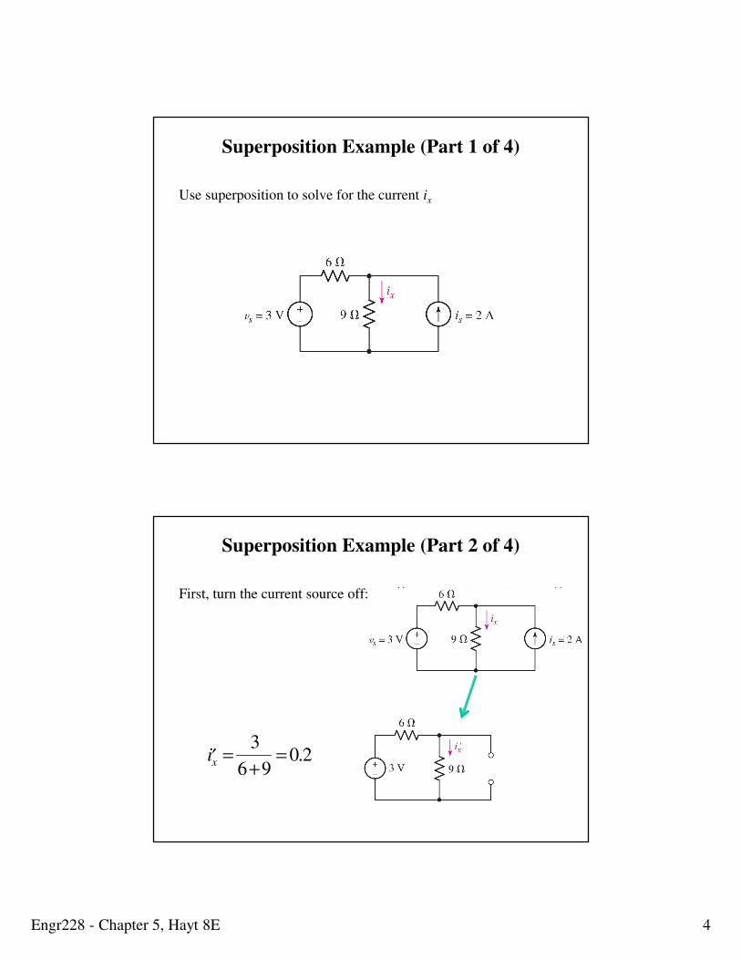
Superposition Example (Part 1 of 4)
Use superposition to solve for the current ix
Superposition Example (Part 2 of 4)
First, turn the current source off:
′ i x =3
6+9= 0.2
Engr228 - Chapter 5, Hayt 8E 5
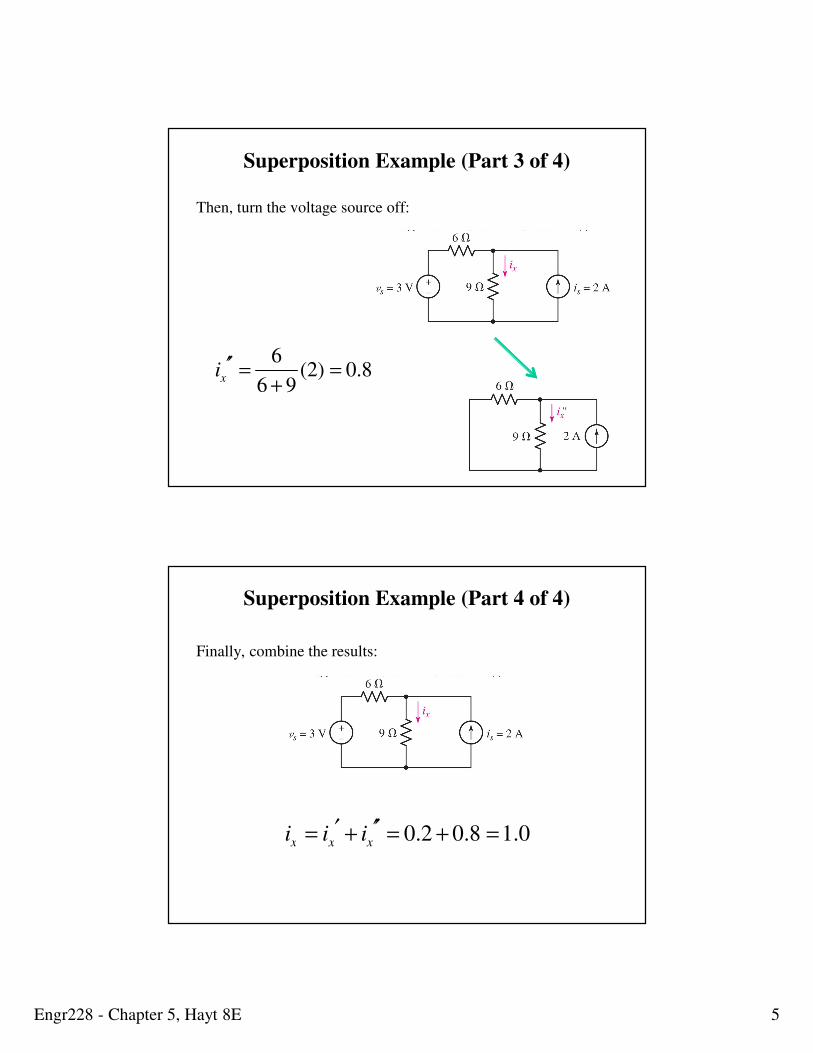
Superposition Example (Part 3 of 4)
Then, turn the voltage source off:
ix′′ =
6
6 + 9(2) = 0.8
Superposition Example (Part 4 of 4)
Finally, combine the results:
ix = ix′ + ix
′′ = 0.2 + 0.8 =1.0
Engr228 - Chapter 5, Hayt 8E 6
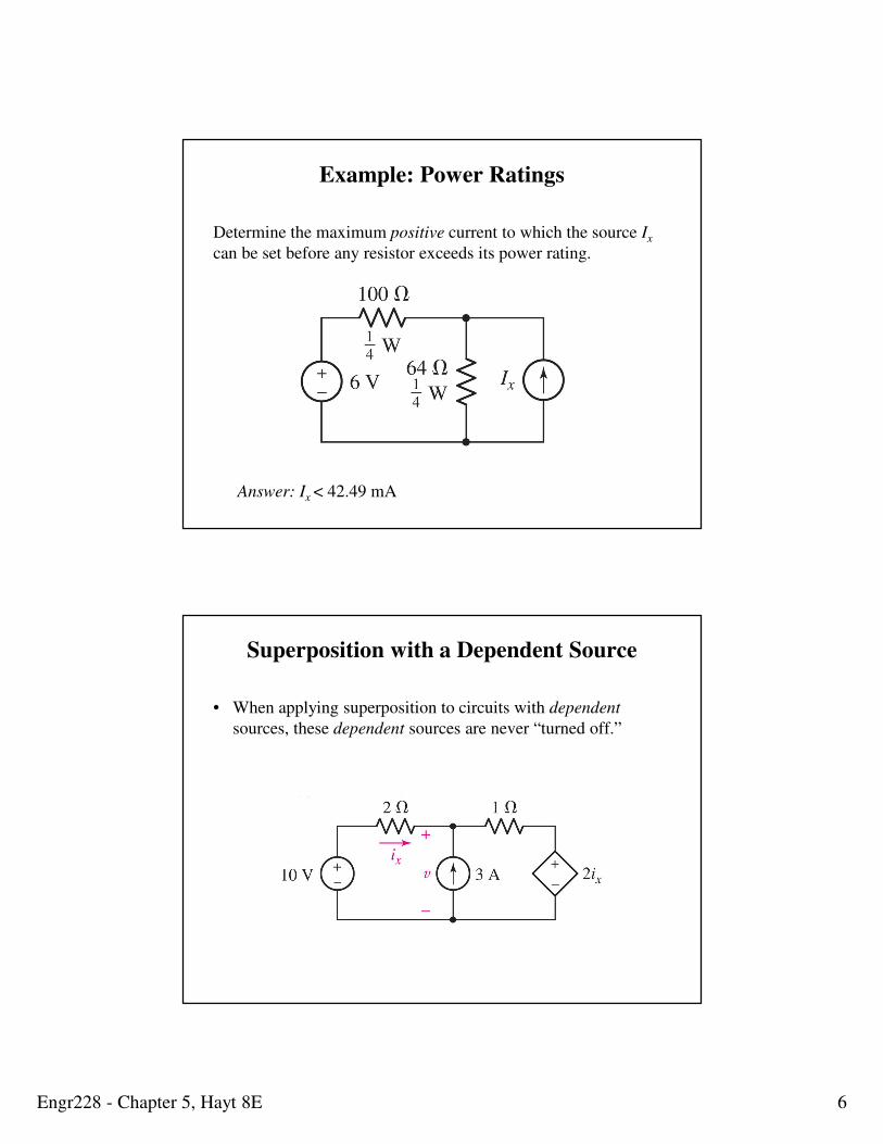
Example: Power Ratings
Determine the maximum positive current to which the source Ix
can be set before any resistor exceeds its power rating.
Answer: Ix < 42.49 mA
Superposition with a Dependent Source
• When applying superposition to circuits with dependent
sources, these dependent sources are never “turned off.”
Engr228 - Chapter 5, Hayt 8E 7
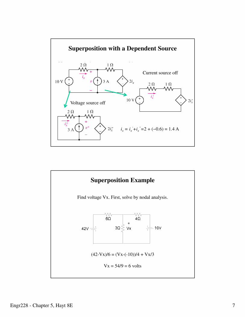
Superposition with a Dependent Source
Current source off
Voltage source off
ix = ix’+ix
’’=2 + (−0.6) = 1.4 A
Superposition Example
Find voltage Vx. First, solve by nodal analysis.
(42-Vx)/6 = (Vx-(-10))/4 + Vx/3
Vx = 54/9 = 6 volts
Engr228 - Chapter 5, Hayt 8E 8
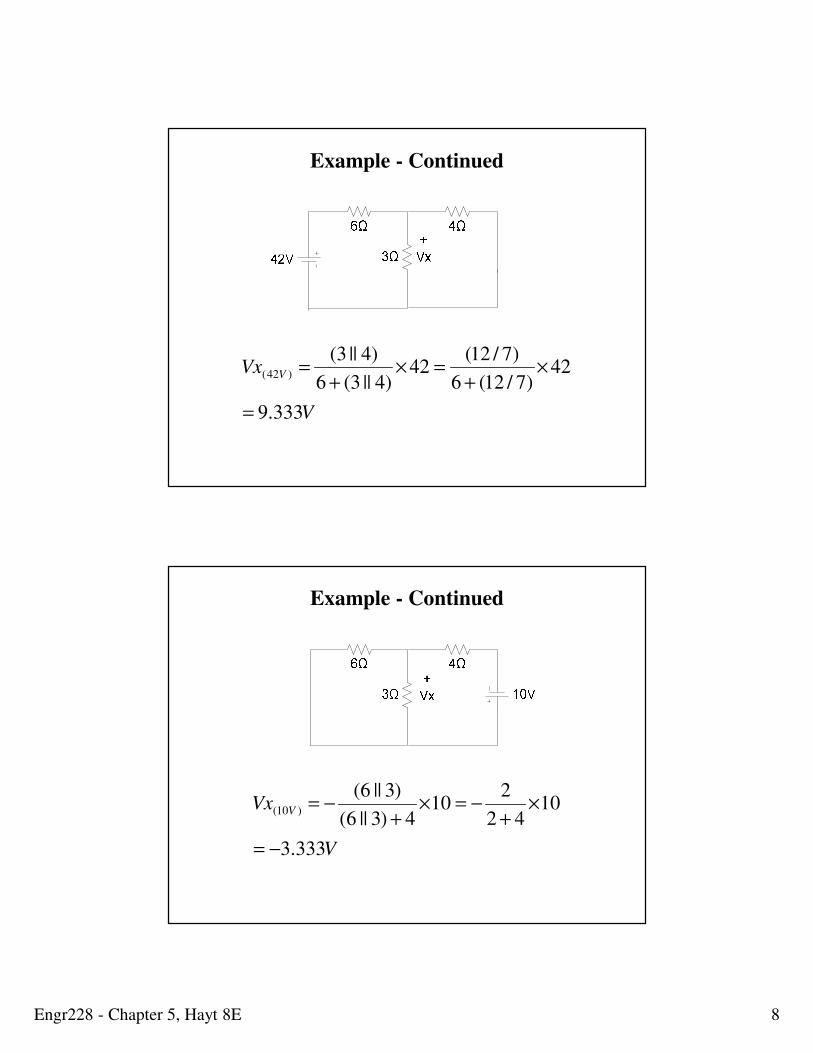
V
Vx V
333.9
42)7/12(6
)7/12(42
)4||3(6
)4||3()42(
=
×+
=×+
=
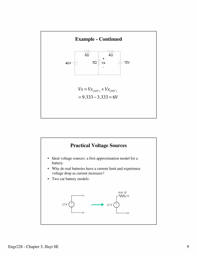
Example - Continued
V
Vx V
333.3
1042
210
4)3||6(
)3||6()10(
−=
×+
−=×+
−=
Example - Continued
Engr228 - Chapter 5, Hayt 8E 9
V
VxVxVx VV
6333.3333.9
)10()42(
=−=
+=
Example - Continued
Practical Voltage Sources
• Ideal voltage sources: a first approximation model for a
battery.
• Why do real batteries have a current limit and experience
voltage drop as current increases?
• Two car battery models:
Engr228 - Chapter 5, Hayt 8E 10
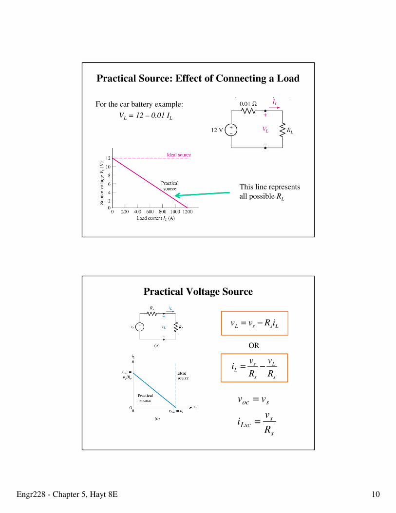
Practical Source: Effect of Connecting a Load
For the car battery example:
VL = 12 – 0.01 IL
This line represents
all possible RL
Practical Voltage Source
s
sLsc
soc
R
vi
vv
=
=
LssL iRvv −=
OR
s
L
s
sL
R
v
R
vi −=
Engr228 - Chapter 5, Hayt 8E 11
Practical Current Source
sLsc
spLoc
ii
iRv
=
=
p
LsL
R
vii −=
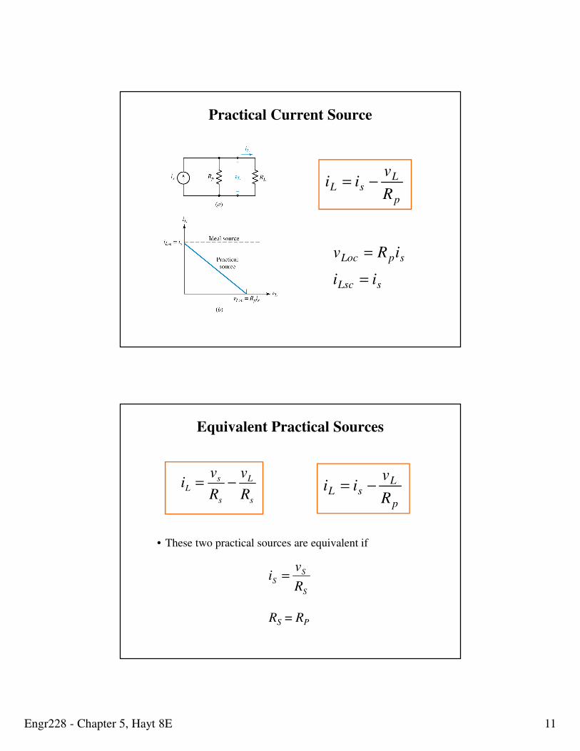
Equivalent Practical Sources
p
LsL
R
vii −=
s
L
s
sL
R
v
R
vi −=
• These two practical sources are equivalent if
RS = RP S
SS
R
vi =
Engr228 - Chapter 5, Hayt 8E 12
Source Transformation and Equivalent Sources
The sources are equivalent if
Rs=Rp and vs=isRs
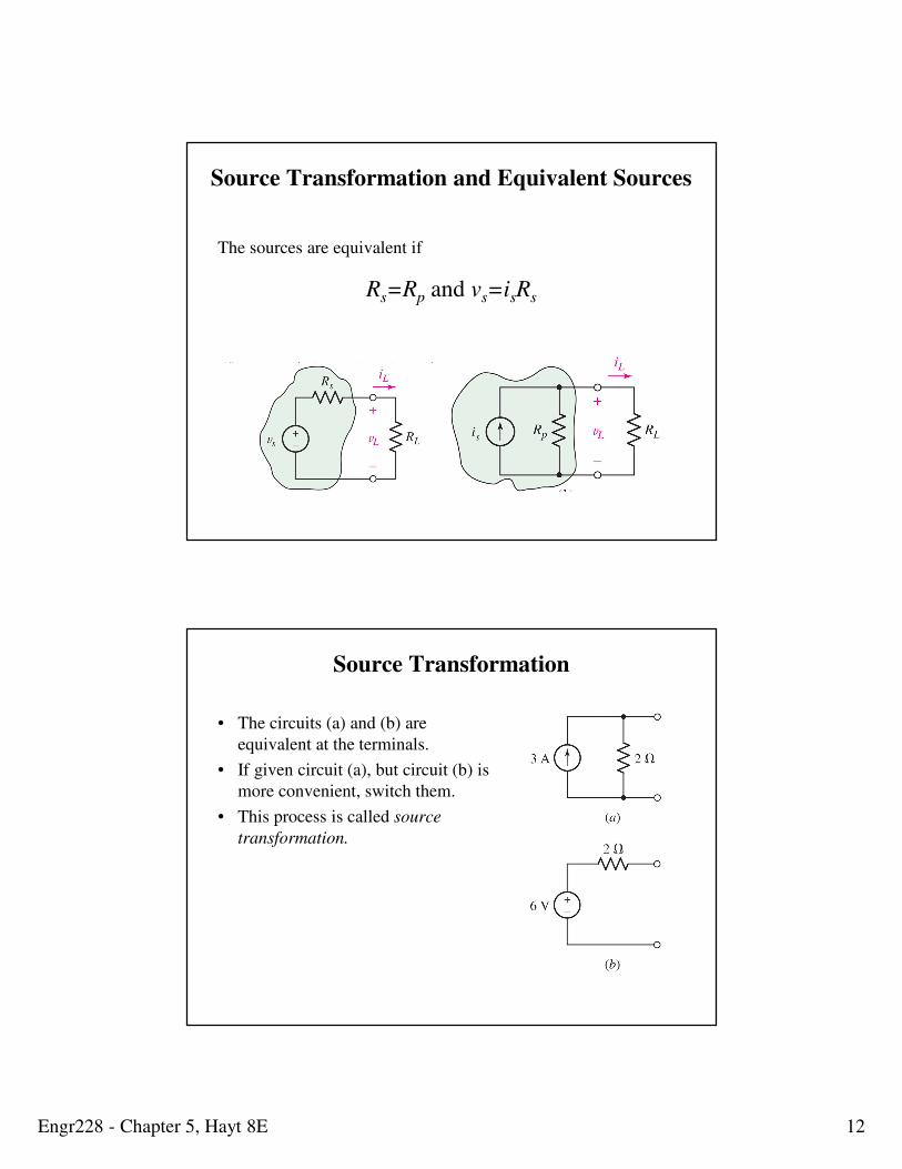
Source Transformation
• The circuits (a) and (b) are
equivalent at the terminals.
• If given circuit (a), but circuit (b) is
more convenient, switch them.
• This process is called source
transformation.
Engr228 - Chapter 5, Hayt 8E 13
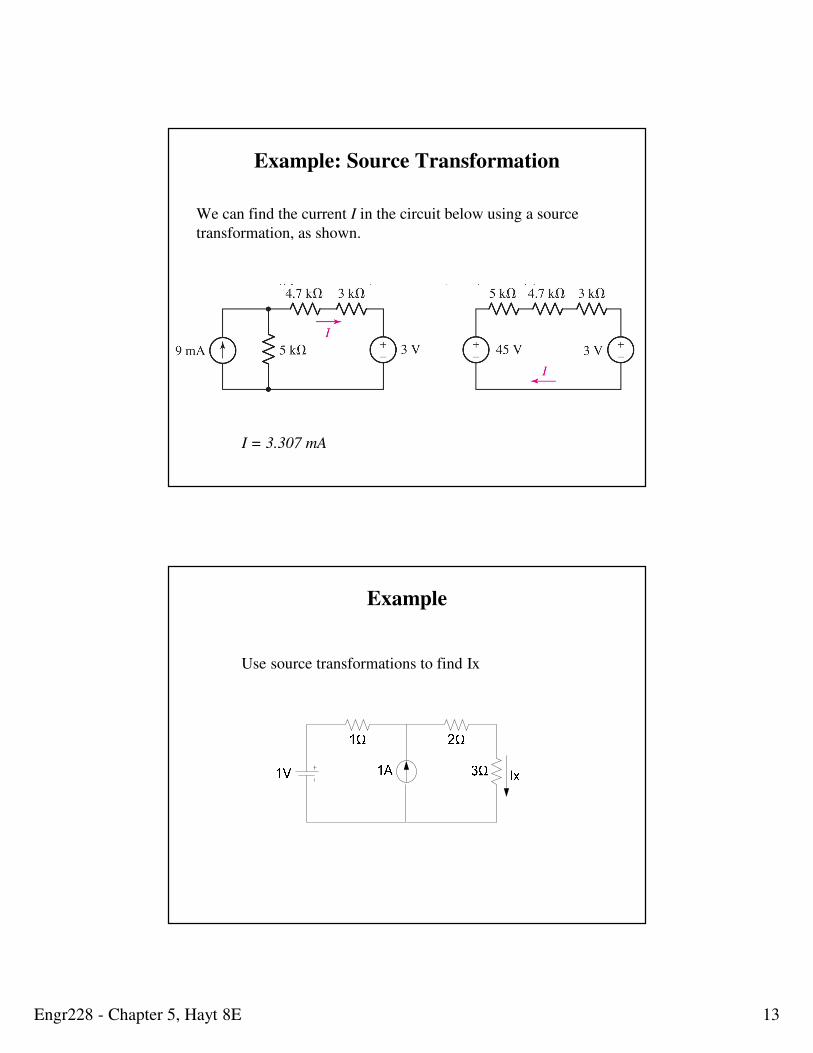
Example: Source Transformation
We can find the current I in the circuit below using a source
transformation, as shown.
I = (45-3)/(5+4.7+3) = 3.307 mA
I = 3.307 mA
Example
Use source transformations to find Ix
Engr228 - Chapter 5, Hayt 8E 14
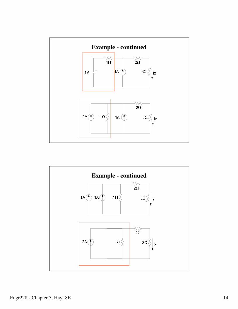
Example - continued
Example - continued
Engr228 - Chapter 5, Hayt 8E 15
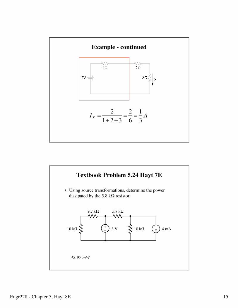
AI X3
1
6
2
321
2==
++=
Example - continued
Textbook Problem 5.24 Hayt 7E
• Using source transformations, determine the power
dissipated by the 5.8 kΩ resistor.
42.97 mW
Engr228 - Chapter 5, Hayt 8E 16
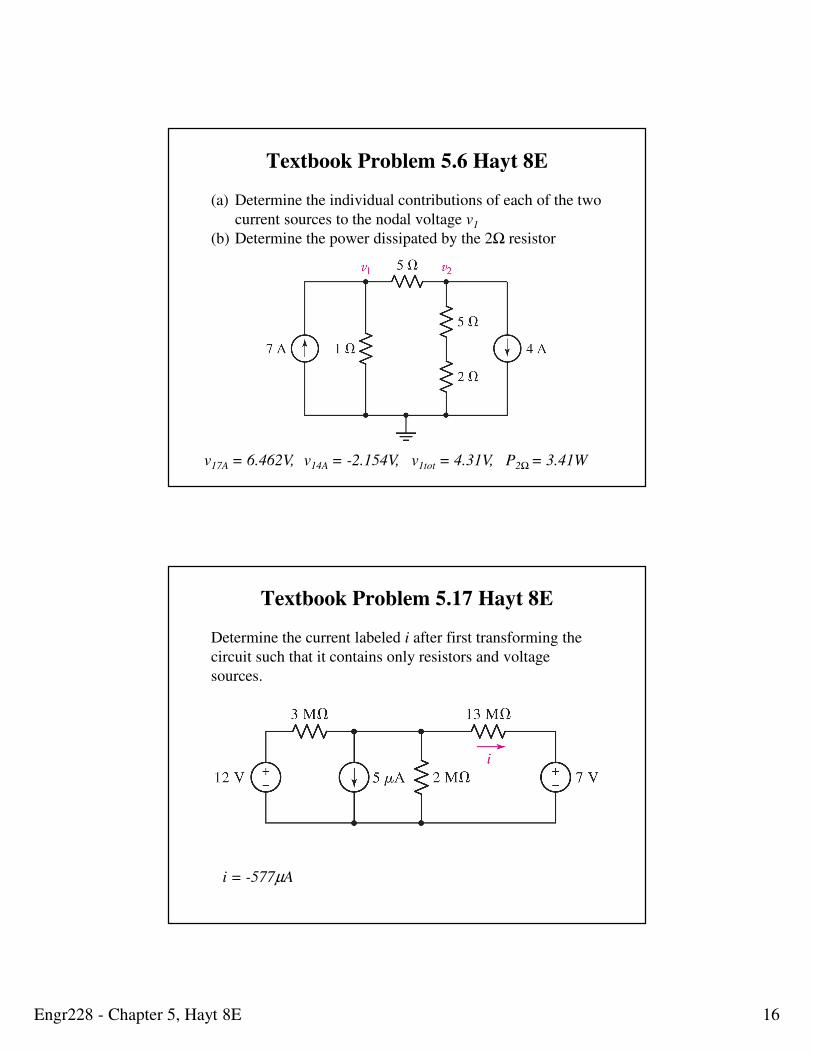
Textbook Problem 5.6 Hayt 8E
(a) Determine the individual contributions of each of the two
current sources to the nodal voltage v1
(b) Determine the power dissipated by the 2Ω resistor
v17A = 6.462V, v14A = -2.154V, v1tot = 4.31V, P2Ω= 3.41W
Textbook Problem 5.17 Hayt 8E
Determine the current labeled i after first transforming the
circuit such that it contains only resistors and voltage
sources.
i = -577µA
Engr228 - Chapter 5, Hayt 8E 17
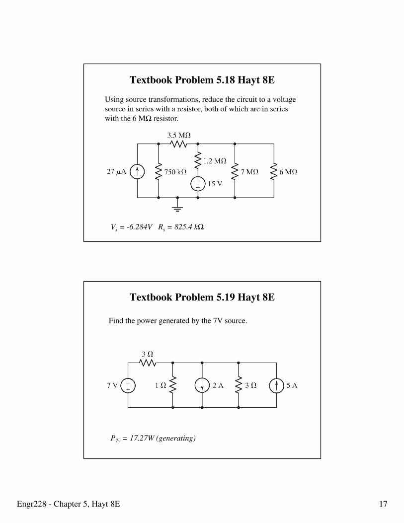
Textbook Problem 5.18 Hayt 8E
Using source transformations, reduce the circuit to a voltage
source in series with a resistor, both of which are in series
with the 6 MΩ resistor.
Vs = -6.284V Rs = 825.4 kΩ
Textbook Problem 5.19 Hayt 8E
P7v = 17.27W (generating)
Find the power generated by the 7V source.
Engr228 - Chapter 5, Hayt 8E 18
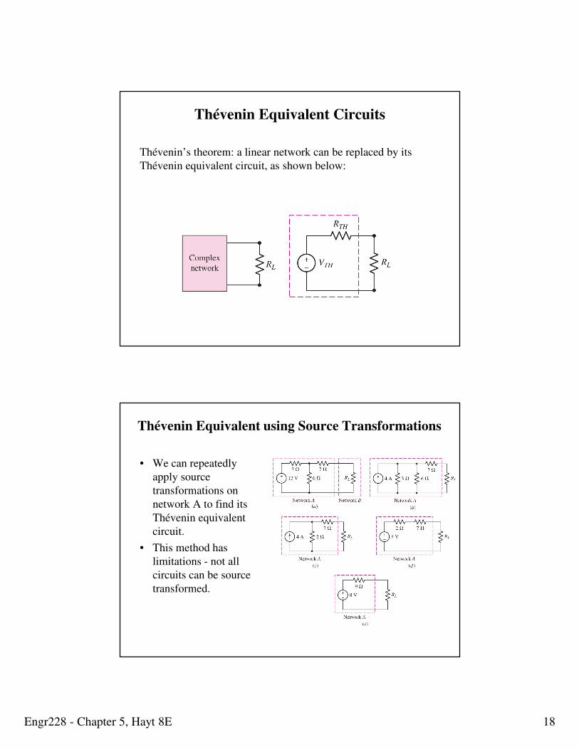
Thévenin Equivalent Circuits
Thévenin’s theorem: a linear network can be replaced by its
Thévenin equivalent circuit, as shown below:
Thévenin Equivalent using Source Transformations
• We can repeatedly
apply source
transformations on
network A to find its
Thévenin equivalent
circuit.
• This method has
limitations - not all
circuits can be source
transformed.
Engr228 - Chapter 5, Hayt 8E 19
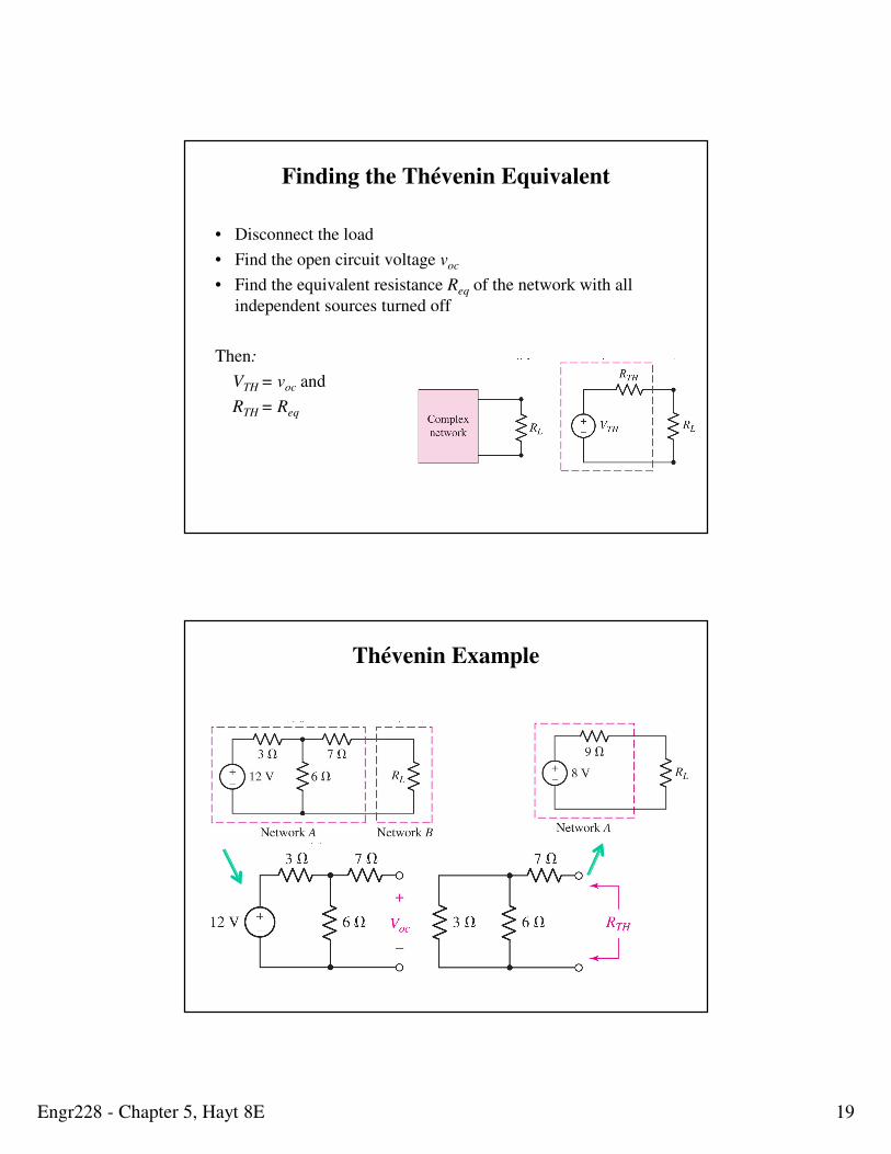
Finding the Thévenin Equivalent
• Disconnect the load
• Find the open circuit voltage voc
• Find the equivalent resistance Req of the network with all
independent sources turned off
Then:
VTH = voc and
RTH = Req
Thévenin Example
Engr228 - Chapter 5, Hayt 8E 20
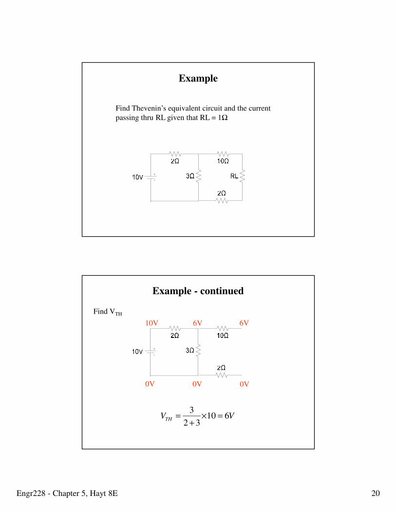
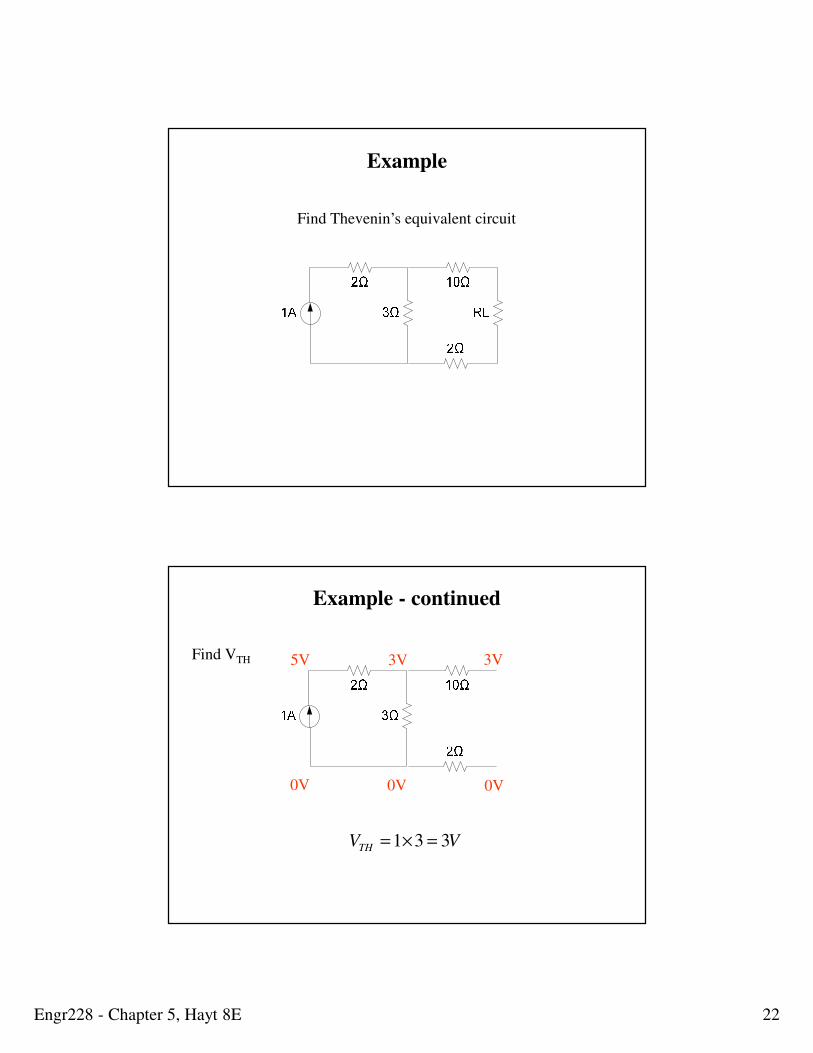
Example
Find Thevenin’s equivalent circuit and the current
passing thru RL given that RL = 1Ω
0V
10V
0V 0V
6V 6V
VVTH 61032
3=×
+=
Find VTH
Example - continued
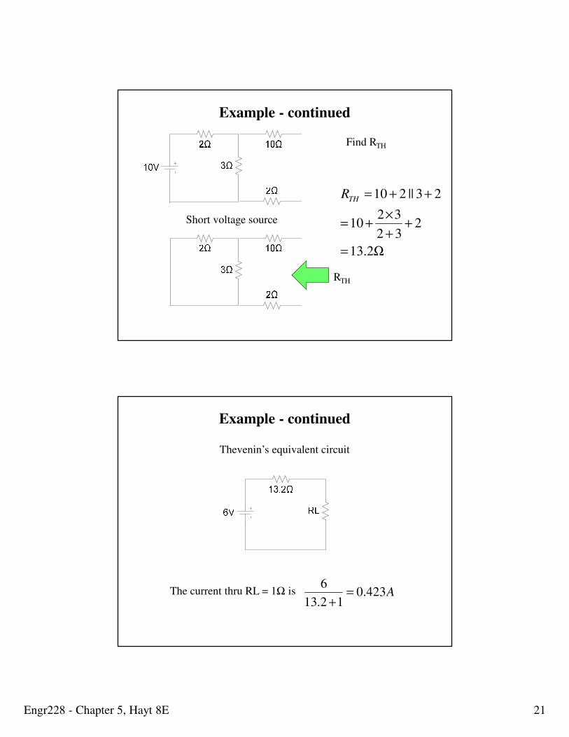
Engr228 - Chapter 5, Hayt 8E 21
Short voltage source
RTH
Ω=
++
×+=
++=
2.13
232
3210
23||210THR
Example - continued
Find RTH
Thevenin’s equivalent circuit
The current thru RL = 1Ω is A423.012.13
6=
+
Example - continued
Engr228 - Chapter 5, Hayt 8E 22
Example
Find Thevenin’s equivalent circuit
Find VTH
0V
5V
0V 0V
3V 3V
VVTH 331 =×=
Example - continued
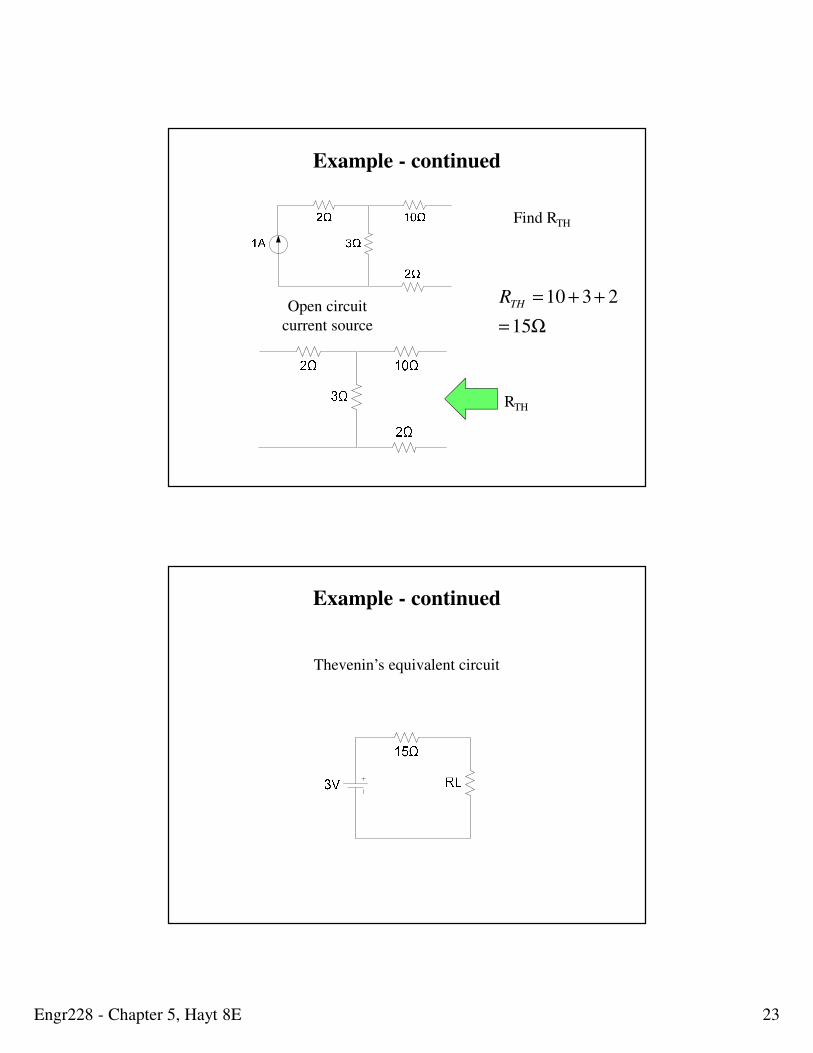
Engr228 - Chapter 5, Hayt 8E 23
Open circuit
current source
RTH
Ω=
++=
15
2310THR
Find RTH
Example - continued
Thevenin’s equivalent circuit
Example - continued
Engr228 - Chapter 5, Hayt 8E 24
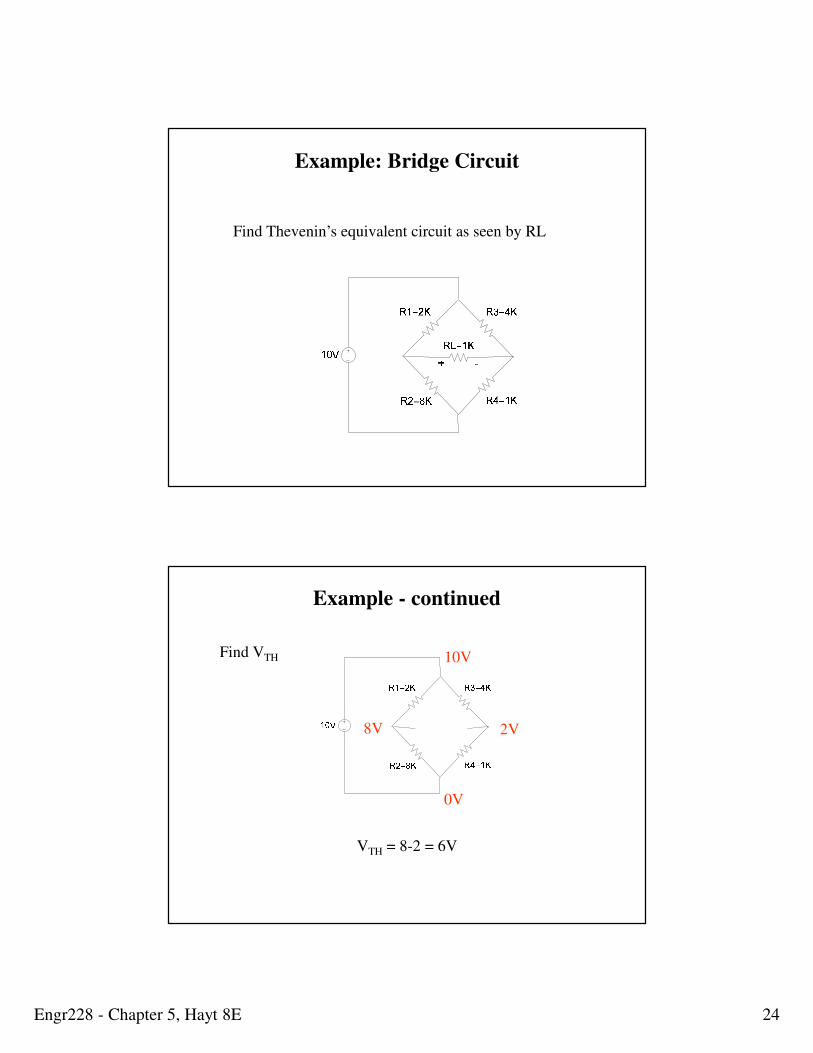
Example: Bridge Circuit
Find Thevenin’s equivalent circuit as seen by RL
Find VTH
0V
10V
8V 2V
VTH = 8-2 = 6V
Example - continued
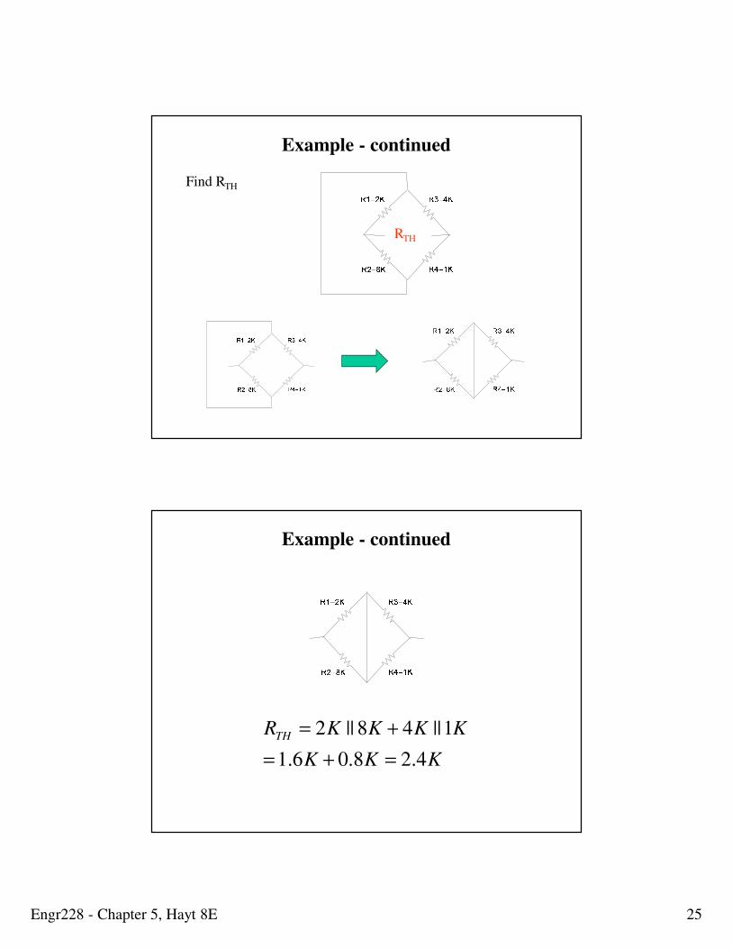
Engr228 - Chapter 5, Hayt 8E 25
Find RTH
RTH
Example - continued
KKK
KKKKRTH
4.28.06.1
1||48||2
=+=
+=
Example - continued
Engr228 - Chapter 5, Hayt 8E 26
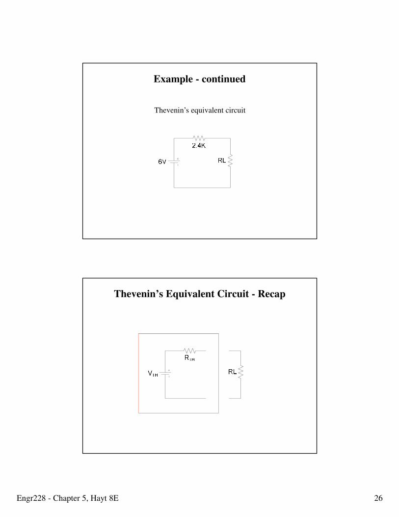
Thevenin’s equivalent circuit
Example - continued
Thevenin’s Equivalent Circuit - Recap
Engr228 - Chapter 5, Hayt 8E 27
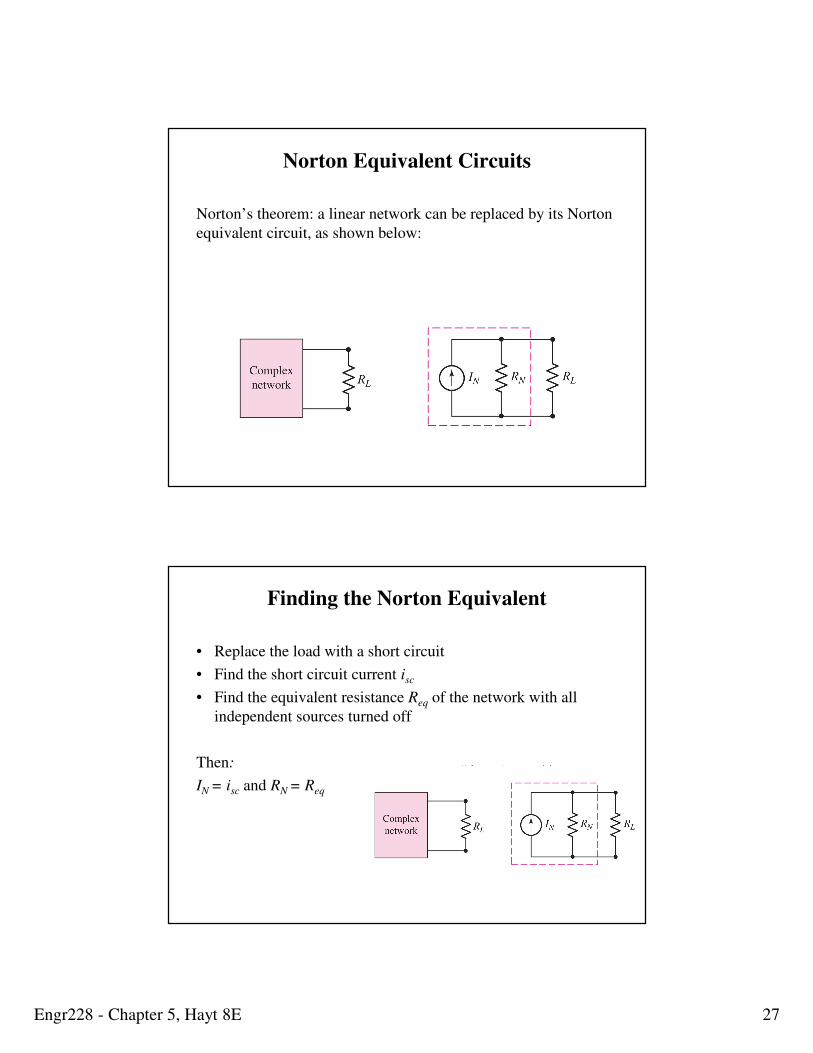
Norton Equivalent Circuits
Norton’s theorem: a linear network can be replaced by its Norton
equivalent circuit, as shown below:
Finding the Norton Equivalent
• Replace the load with a short circuit
• Find the short circuit current isc
• Find the equivalent resistance Req of the network with all
independent sources turned off
Then:
IN = isc and RN = Req
Engr228 - Chapter 5, Hayt 8E 28
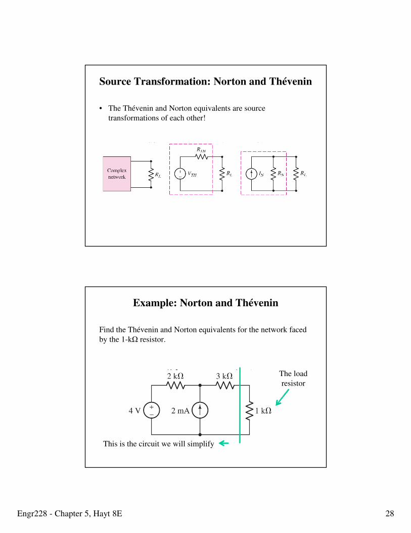
Source Transformation: Norton and Thévenin
• The Thévenin and Norton equivalents are source
transformations of each other!
RTH=RN =Req and vTH=iNReq
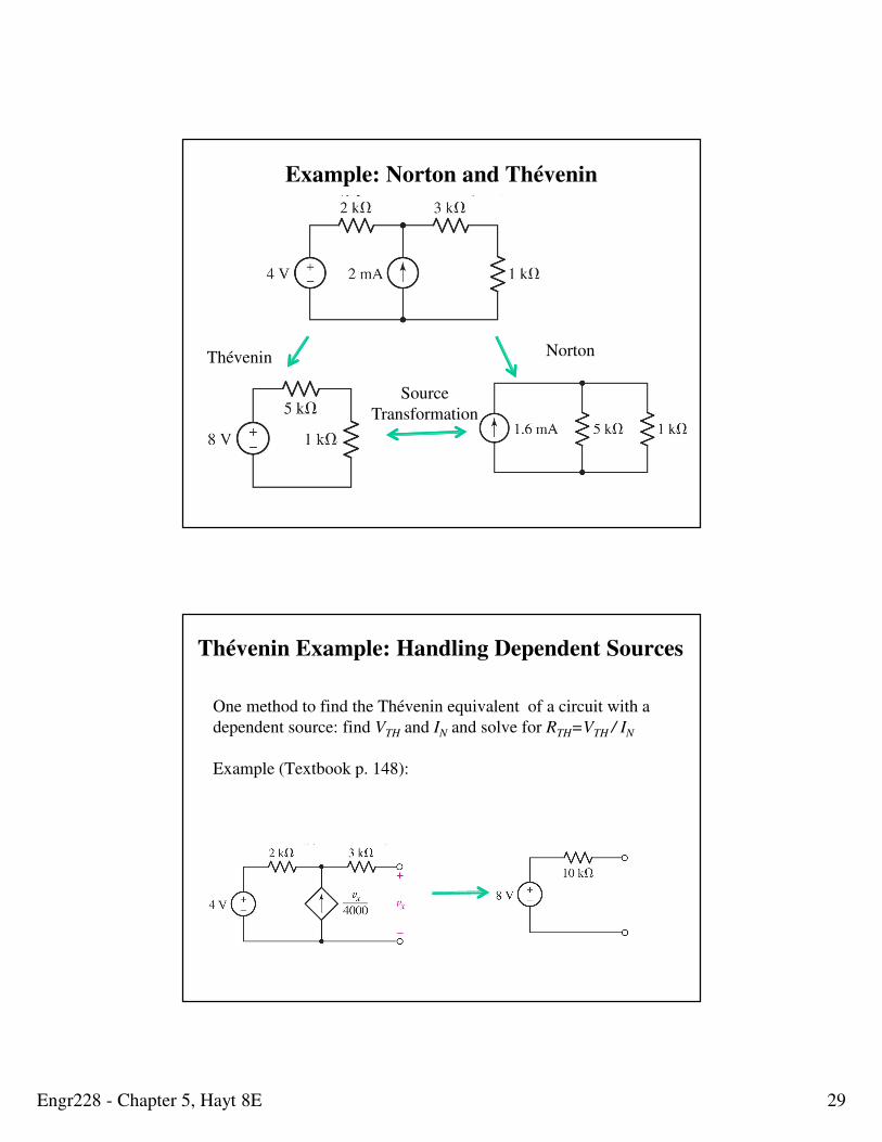
Example: Norton and Thévenin
Find the Thévenin and Norton equivalents for the network faced
by the 1-kΩ resistor.
The load
resistor
This is the circuit we will simplify
Engr228 - Chapter 5, Hayt 8E 29
Example: Norton and Thévenin
NortonThévenin
Source
Transformation
One method to find the Thévenin equivalent of a circuit with a
dependent source: find VTH and IN and solve for RTH=VTH / IN
Example (Textbook p. 148):
Thévenin Example: Handling Dependent Sources
Engr228 - Chapter 5, Hayt 8E 30
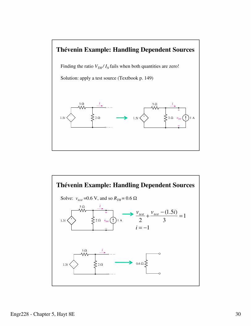
Thévenin Example: Handling Dependent Sources
Finding the ratio VTH / IN fails when both quantities are zero!
Solution: apply a test source (Textbook p. 149)
Thévenin Example: Handling Dependent Sources
Solve: vtest =0.6 V, and so RTH = 0.6 Ω
v test
2+
v test − (1.5i)
3=1
i = −1
Engr228 - Chapter 5, Hayt 8E 31
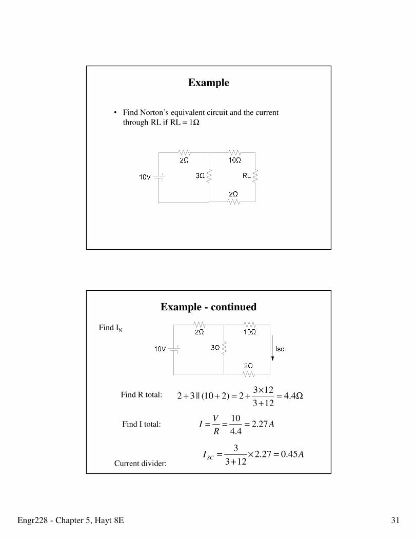
Example
• Find Norton’s equivalent circuit and the current
through RL if RL = 1Ω
Find IN
Find R total:
Find I total:
Current divider:
Ω=+
×+=++ 4.4
123
1232)210(||32
AR
VI 27.2
4.4
10===
AI SC 45.027.2123
3=×
+=
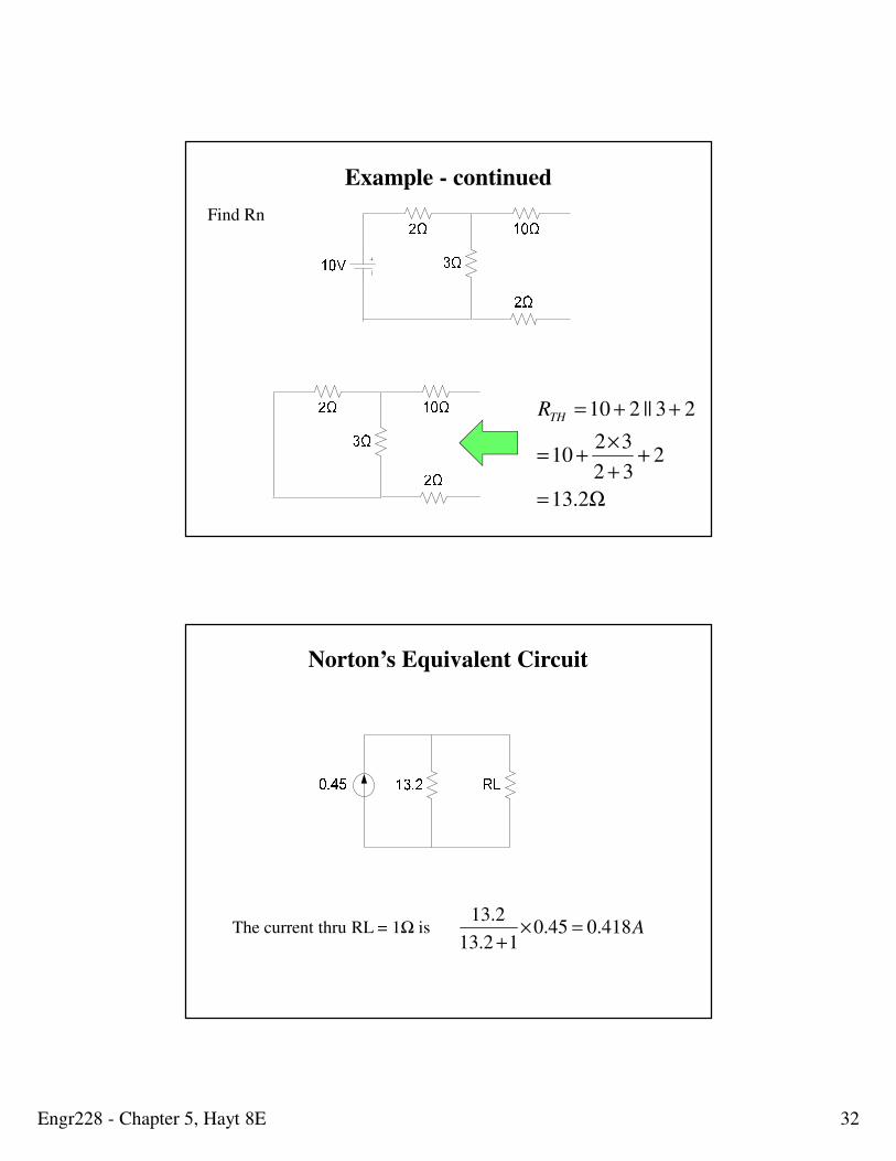
Example - continued
Engr228 - Chapter 5, Hayt 8E 32
Ω=
++
×+=
++=
2.13
232
3210
23||210THR
Find Rn
Example - continued
Norton’s Equivalent Circuit
The current thru RL = 1Ω is A418.045.012.13
2.13=×
+
Engr228 - Chapter 5, Hayt 8E 33
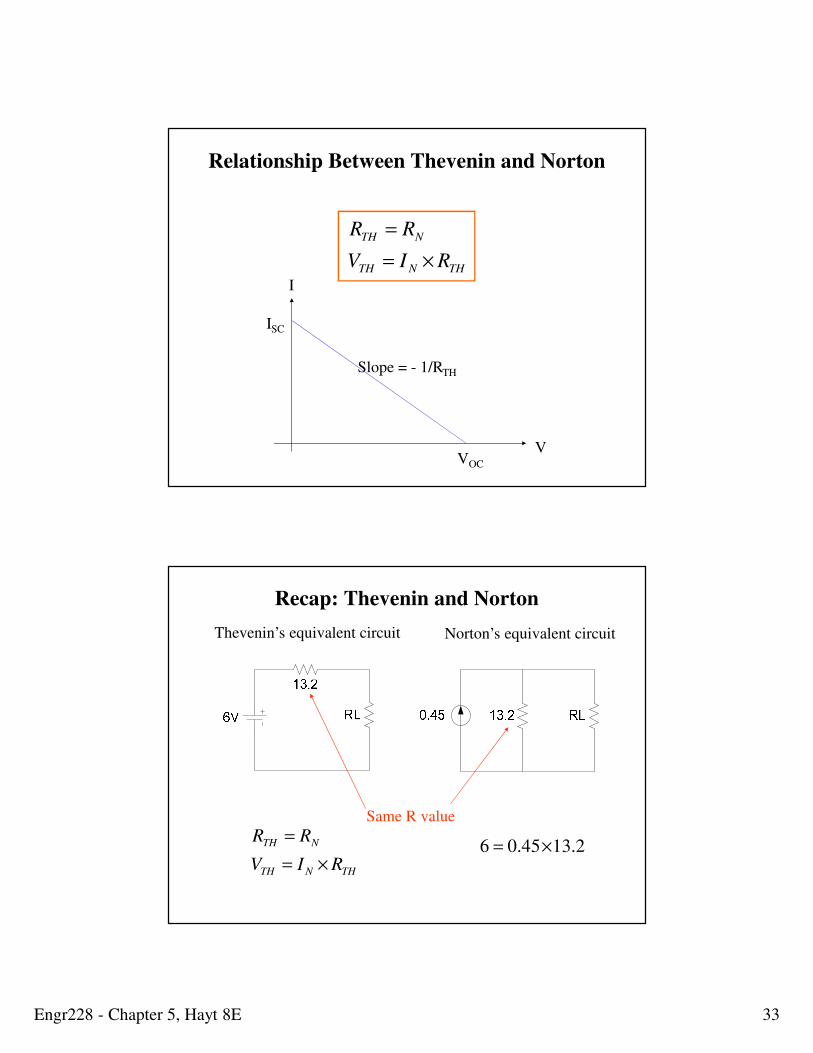
Relationship Between Thevenin and Norton
I
VVOC
ISC
Slope = - 1/RTH
THNTH
NTH
RIV
RR
×=
=
Norton’s equivalent circuitThevenin’s equivalent circuit
Same R value
2.1345.06 ×=
THNTH
NTH
RIV
RR
×=
=
Recap: Thevenin and Norton
Engr228 - Chapter 5, Hayt 8E 34
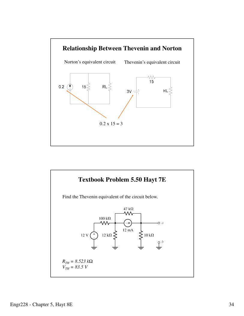
Thevenin’s equivalent circuitNorton’s equivalent circuit
0.2 x 15 = 3
Relationship Between Thevenin and Norton
Textbook Problem 5.50 Hayt 7E
Find the Thevenin equivalent of the circuit below.
RTH = 8.523 kΩ
VTH = 83.5 V
Engr228 - Chapter 5, Hayt 8E 35
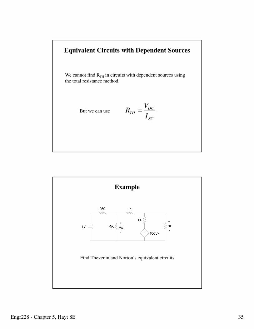
Equivalent Circuits with Dependent Sources
We cannot find RTH in circuits with dependent sources using
the total resistance method.
But we can use
SC
OCTH
I
VR =
Example
Find Thevenin and Norton’s equivalent circuits
Engr228 - Chapter 5, Hayt 8E 36
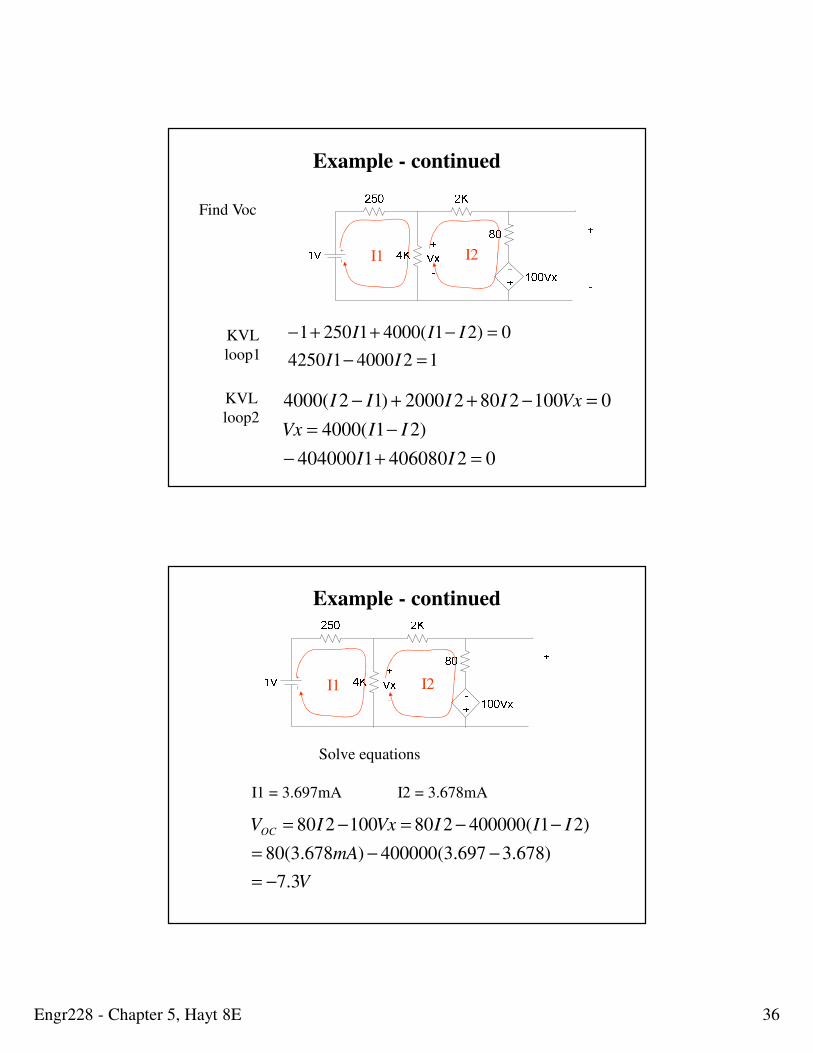
Find Voc
I1 I2
12400014250
0)21(400012501
=−
=−++−
II
IIIKVL
loop1
024060801404000
)21(4000
010028022000)12(4000
=+−
−=
=−++−
II
IIVx
VxIIIIKVL
loop2
Example - continued
I1 I2
Solve equations
I1 = 3.697mA I2 = 3.678mA
V
mA
IIIVxIVOC
3.7
)678.3697.3(400000)678.3(80
)21(400000280100280
−=
−−=
−−=−=
Example - continued
Engr228 - Chapter 5, Hayt 8E 37
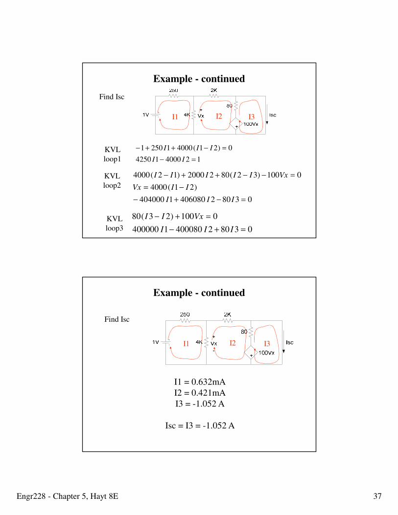
Find Isc
I1 I2 I3
12400014250
0)21(400012501
=−
=−++−
II
IIIKVL
loop1
038024060801404000
)21(4000
0100)32(8022000)12(4000
=−+−
−=
=−−++−
III
IIVx
VxIIIIIKVL
loop2
KVL
loop3 038024000801400000
0100)23(80
=+−
=+−
III
VxII
Example - continued
Find Isc
I1 I2 I3
I1 = 0.632mA
I2 = 0.421mA
I3 = -1.052 A
Isc = I3 = -1.052 A
Example - continued
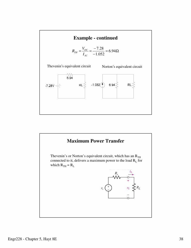
Engr228 - Chapter 5, Hayt 8E 38
Ω=−
−== 94.6
052.1
28.7
SC
OCTH
I
VR
Thevenin’s equivalent circuit Norton’s equivalent circuit
Example - continued
Maximum Power Transfer
Thevenin’s or Norton’s equivalent circuit, which has an RTH
connected to it, delivers a maximum power to the load RL for
which RTH = RL
Engr228 - Chapter 5, Hayt 8E 39
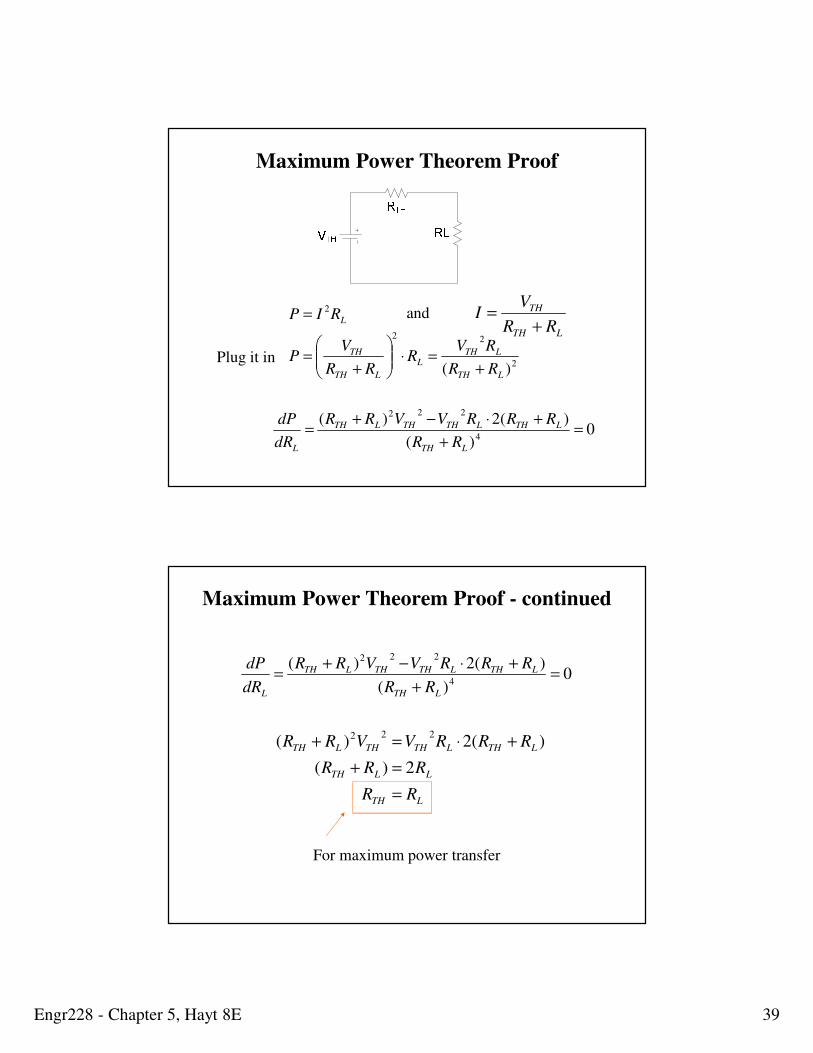
2
22
2
)( LTH
LTHL
LTH
TH
L
RR
RVR
RR
VP
RIP
+=⋅
+=
=LTH
TH
RR
VI
+=and
Plug it in
0)(
)(2)(4
222
=+
+⋅−+=
LTH
LTHLTHTHLTH
L RR
RRRVVRR
dR
dP
Maximum Power Theorem Proof
LTH
LLTH
LTHLTHTHLTH
RR
RRR
RRRVVRR
=
=+
+⋅=+
2)(
)(2)(222
0)(
)(2)(4
222
=+
+⋅−+=
LTH
LTHLTHTHLTH
L RR
RRRVVRR
dR
dP
For maximum power transfer
Maximum Power Theorem Proof - continued
Engr228 - Chapter 5, Hayt 8E 40
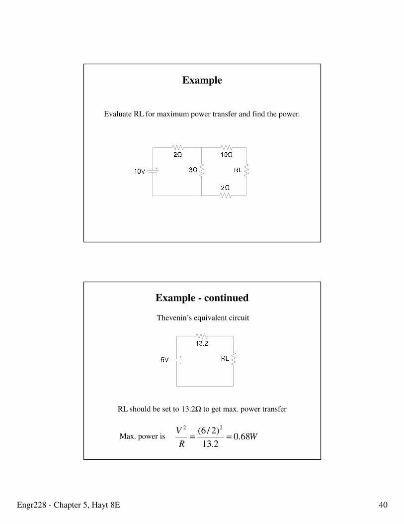
Example
Evaluate RL for maximum power transfer and find the power.
Thevenin’s equivalent circuit
RL should be set to 13.2Ω to get max. power transfer
Max. power is WR
V68.0
2.13
)2/6( 22
==
Example - continued

Engr228 - Chapter 5, Hayt 8E 41
Chapter 5 Summary
• Stated and applied the property of linearity
• Stated and explored the property of superposition
• Investigated source transformations
• Defined and constructed the Thevenin and Norton
equivalent circuits
• Investigated maximum power transfer to a load


![Engineering electromagnetics 6th edition [william h. hayt]](https://img.pdfslide.us/doc/110x75/549ec457ac795947768b4884/engineering-electromagnetics-6th-edition-william-h-hayt.jpg)