Embed Size (px)
Citation preview
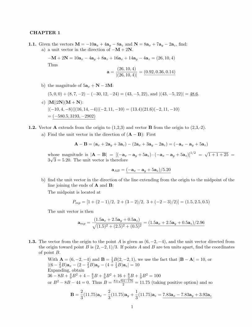
CHAPTER 1
1.1. Given the vectors M = −10ax + 4ay − 8az and N = 8ax + 7ay − 2az, find:a) a unit vector in the direction of −M + 2N.
−M + 2N = 10ax − 4ay + 8az + 16ax + 14ay − 4az = (26, 10, 4)Thus
a =(26, 10, 4)|(26, 10, 4)| = (0.92, 0.36, 0.14)
b) the magnitude of 5ax + N− 3M:
(5, 0, 0) + (8, 7,−2)− (−30, 12,−24) = (43,−5, 22), and |(43,−5, 22)| = 48.6.
c) |M||2N|(M + N):|(−10, 4,−8)||(16, 14,−4)|(−2, 11,−10) = (13.4)(21.6)(−2, 11,−10)= (−580.5, 3193,−2902)
1.2. Vector A extends from the origin to (1,2,3) and vector B from the origin to (2,3,-2).a) Find the unit vector in the direction of (A−B): First
A−B = (ax + 2ay + 3az)− (2ax + 3ay − 2az) = (−ax − ay + 5az)
whose magnitude is |A − B| = [(−ax − ay + 5az) · (−ax − ay + 5az)]1/2 =
√1 + 1 + 25 =
3√
3 = 5.20. The unit vector is therefore
aAB = (−ax − ay + 5az)/5.20
b) find the unit vector in the direction of the line extending from the origin to the midpoint of theline joining the ends of A and B:The midpoint is located at
Pmp = [1 + (2− 1)/2, 2 + (3− 2)/2, 3 + (−2− 3)/2)] = (1.5, 2.5, 0.5)
The unit vector is then
amp =(1.5ax + 2.5ay + 0.5az)p(1.5)2 + (2.5)2 + (0.5)2
= (1.5ax + 2.5ay + 0.5az)/2.96
1.3. The vector from the origin to the point A is given as (6,−2,−4), and the unit vector directed fromthe origin toward point B is (2,−2, 1)/3. If points A and B are ten units apart, find the coordinatesof point B.
With A = (6,−2,−4) and B = 13B(2,−2, 1), we use the fact that |B−A| = 10, or
|(6− 23B)ax − (2− 2
3B)ay − (4 + 13B)az| = 10
Expanding, obtain36− 8B + 4
9B2 + 4− 83B + 4
9B2 + 16 + 83B + 1
9B2 = 100or B2 − 8B − 44 = 0. Thus B = 8±
√64−1762 = 11.75 (taking positive option) and so
B =23(11.75)ax −
23(11.75)ay +
13(11.75)az = 7.83ax − 7.83ay + 3.92az
1
1.4. A circle, centered at the origin with a radius of 2 units, lies in the xy plane. Determine the unitvector in rectangular components that lies in the xy plane, is tangent to the circle at (−
√3, 1, 0),
and is in the general direction of increasing values of y:A unit vector tangent to this circle in the general increasing y direction is t = −aφ. Its x andy components are tx = −aφ · ax = sinφ, and ty = −aφ · ay = − cosφ. At the point (−
√3, 1),
φ = 150, and so t = sin 150ax − cos 150ay = 0.5(ax +√
3ay).
1.5. A vector field is specified as G = 24xyax + 12(x2 + 2)ay + 18z2az. Given two points, P (1, 2,−1)and Q(−2, 1, 3), find:a) G at P : G(1, 2,−1) = (48, 36, 18)b) a unit vector in the direction of G at Q: G(−2, 1, 3) = (−48, 72, 162), so
aG =(−48, 72, 162)|(−48, 72, 162)| = (−0.26, 0.39, 0.88)
c) a unit vector directed from Q toward P :
aQP =P−Q|P−Q| =
(3,−1, 4)√26
= (0.59, 0.20,−0.78)
d) the equation of the surface on which |G| = 60: We write 60 = |(24xy, 12(x2 + 2), 18z2)|, or10 = |(4xy, 2x2 + 4, 3z2)|, so the equation is
100 = 16x2y2 + 4x4 + 16x2 + 16 + 9z4
1.6. Find the acute angle between the two vectors A = 2ax + ay + 3az and B = ax− 3ay + 2az by usingthe definition of:a) the dot product: First, A · B = 2 − 3 + 6 = 5 = AB cos θ, where A =
√22 + 12 + 32 =
√14,
and where B =√
12 + 32 + 22 =√
14. Therefore cos θ = 5/14, so that θ = 69.1.b) the cross product: Begin with
A×B =
ØØØØØØ
ax ay az
2 1 31 −3 2
ØØØØØØ= 11ax − ay − 7az
and then |A×B| =√
112 + 12 + 72 =√
171. So now, with |A×B| = AB sin θ =√
171,find θ = sin−1
°√171/14
¢= 69.1
1.7. Given the vector field E = 4zy2 cos 2xax + 2zy sin 2xay + y2 sin 2xaz for the region |x|, |y|, and |z|less than 2, find:a) the surfaces on which Ey = 0. With Ey = 2zy sin 2x = 0, the surfaces are 1) the plane z = 0,
with |x| < 2, |y| < 2; 2) the plane y = 0, with |x| < 2, |z| < 2; 3) the plane x = 0, with |y| < 2,|z| < 2; 4) the plane x = π/2, with |y| < 2, |z| < 2.
b) the region in which Ey = Ez: This occurs when 2zy sin 2x = y2 sin 2x, or on the plane 2z = y,with |x| < 2, |y| < 2, |z| < 1.
c) the region in which E = 0: We would have Ex = Ey = Ez = 0, or zy2 cos 2x = zy sin 2x =y2 sin 2x = 0. This condition is met on the plane y = 0, with |x| < 2, |z| < 2.
2
1.8. Demonstrate the ambiguity that results when the cross product is used to find the angle betweentwo vectors by finding the angle between A = 3ax − 2ay + 4az and B = 2ax + ay − 2az. Does thisambiguity exist when the dot product is used?
We use the relation A×B = |A||B| sin θn. With the given vectors we find
A×B = 14ay + 7az = 7√
5∑2ay + az√
5
∏
| z ±n
=√
9 + 4 + 16√
4 + 1 + 4 sin θ n
where n is identified as shown; we see that n can be positive or negative, as sin θ can bepositive or negative. This apparent sign ambiguity is not the real problem, however, as wereally want the magnitude of the angle anyway. Choosing the positive sign, we are left withsin θ = 7
√5/(√
29√
9) = 0.969. Two values of θ (75.7 and 104.3) satisfy this equation, andhence the real ambiguity.In using the dot product, we find A · B = 6 − 2 − 8 = −4 = |A||B| cos θ = 3
√29 cos θ, or
cos θ = −4/(3√
29) = −0.248 ⇒ θ = −75.7. Again, the minus sign is not important, as wecare only about the angle magnitude. The main point is that only one θ value results whenusing the dot product, so no ambiguity.
1.9. A field is given as
G =25
(x2 + y2)(xax + yay)
Find:a) a unit vector in the direction of G at P (3, 4,−2): Have Gp = 25/(9+16)×(3, 4, 0) = 3ax +4ay,
and |Gp| = 5. Thus aG = (0.6, 0.8, 0).b) the angle between G and ax at P : The angle is found through aG · ax = cos θ. So cos θ =
(0.6, 0.8, 0) · (1, 0, 0) = 0.6. Thus θ = 53.c) the value of the following double integral on the plane y = 7:
Z 4
0
Z 2
0G · aydzdx
Z 4
0
Z 2
0
25x2 + y2
(xax + yay) · aydzdx =Z 4
0
Z 2
0
25x2 + 49
× 7 dzdx =Z 4
0
350x2 + 49
dx
= 350× 17
∑tan−1
µ47
∂− 0
∏= 26
1.10. By expressing diagonals as vectors and using the definition of the dot product, find the smaller anglebetween any two diagonals of a cube, where each diagonal connects diametrically opposite corners,and passes through the center of the cube:
Assuming a side length, b, two diagonal vectors would be A = b(ax + ay + az) and B =b(ax − ay + az). Now use A · B = |A||B| cos θ, or b2(1− 1 + 1) = (
√3b)(√
3b) cos θ ⇒ cos θ =1/3 ⇒ θ = 70.53. This result (in magnitude) is the same for any two diagonal vectors.
3
1.11. Given the points M(0.1,−0.2,−0.1), N(−0.2, 0.1, 0.3), and P (0.4, 0, 0.1), find:a) the vector RMN : RMN = (−0.2, 0.1, 0.3)− (0.1,−0.2,−0.1) = (−0.3, 0.3, 0.4).b) the dot product RMN · RMP : RMP = (0.4, 0, 0.1)− (0.1,−0.2,−0.1) = (0.3, 0.2, 0.2). RMN ·
RMP = (−0.3, 0.3, 0.4) · (0.3, 0.2, 0.2) = −0.09 + 0.06 + 0.08 = 0.05.c) the scalar projection of RMN on RMP :
RMN · aRMP = (−0.3, 0.3, 0.4) · (0.3, 0.2, 0.2)√0.09 + 0.04 + 0.04
=0.05√0.17
= 0.12
d) the angle between RMN and RMP :
θM = cos−1
µRMN · RMP
|RMN ||RMP |
∂= cos−1
µ0.05√
0.34√
0.17
∂= 78
1.12. Write an expression in rectangular components for the vector that extends from (x1, y1, z1) to(x2, y2, z2) and determine the magnitude of this vector.
The two points can be written as vectors from the origin:
A1 = x1ax + y1ay + z1az and A2 = x2ax + y2ay + z2az
The desired vector will now be the difference:
A12 = A2 −A1 = (x2 − x1)ax + (y2 − y1)ay + (z2 − z1)az
whose magnitude is
|A12| =p
A12 · A12 =£(x2 − x1)2 + (y2 − y1)2 + (z2 − z1)2
§1/2
1.13. a) Find the vector component of F = (10,−6, 5) that is parallel to G = (0.1, 0.2, 0.3):
F||G =F · G|G|2 G =
(10,−6, 5) · (0.1, 0.2, 0.3)0.01 + 0.04 + 0.09
(0.1, 0.2, 0.3) = (0.93, 1.86, 2.79)
b) Find the vector component of F that is perpendicular to G:
FpG = F− F||G = (10,−6, 5)− (0.93, 1.86, 2.79) = (9.07,−7.86, 2.21)
c) Find the vector component of G that is perpendicular to F:
GpF = G−G||F = G− G · F|F|2 F = (0.1, 0.2, 0.3)− 1.3
100 + 36 + 25(10,−6, 5) = (0.02, 0.25, 0.26)
4
1.14. Given that A + B + C = 0, where the three vectors represent line segments and extend from acommon origin,a) must the three vectors be coplanar?
In terms of the components, the vector sum will be
A + B + C = (Ax + Bx + Cx)ax + (Ay + By + Cy)ay + (Az + Bz + Cz)az
which we require to be zero. Suppose the coordinate system is configured so that vectors Aand B lie in the x-y plane; in this case Az = Bz = 0. Then Cz has to be zero in order for thethree vectors to sum to zero. Therefore, the three vectors must be coplanar.
b) If A + B + C + D = 0, are the four vectors coplanar?
The vector sum is now
A + B + C + D = (Ax + Bx + Cx + Dx)ax + (Ay + By + Cy + Dy)ay + (Az + Bz + Cz + Dz)az
Now, for example, if A and B lie in the x-y plane, C and D need not, as long as Cz + Dz = 0.So the four vectors need not be coplanar to have a zero sum.
1.15. Three vectors extending from the origin are given as r1 = (7, 3,−2), r2 = (−2, 7,−3), and r3 =(0, 2, 3). Find:a) a unit vector perpendicular to both r1 and r2:
ap12 =r1 × r2
|r1 × r2| =(5, 25, 55)
60.6= (0.08, 0.41, 0.91)
b) a unit vector perpendicular to the vectors r1−r2 and r2−r3: r1−r2 = (9,−4, 1) and r2−r3 =(−2, 5,−6). So r1 − r2 × r2 − r3 = (19, 52, 32). Then
ap =(19, 52, 32)|(19, 52, 32)| =
(19, 52, 32)63.95
= (0.30, 0.81, 0.50)
c) the area of the triangle defined by r1 and r2:
Area =12
|r1 × r2| = 30.3
d) the area of the triangle defined by the heads of r1, r2, and r3:
Area =12
|(r2 − r1)× (r2 − r3)| =12
|(−9, 4,−1)× (−2, 5,−6)| = 32.0
5
1.16. If A represents a vector one unit in length directed due east, B represents a vector three units inlength directed due north, and A + B = 2C−D and 2A−B = C + 2D, determine the length anddirection of C. (difficulty 1)
Take north as the positive y direction, and then east as the positive x direction. Then we may write
A + B = ax + 3ay = 2C−D
and2A−B = 2ax − 3ay = C + 2D
Multiplying the first equation by 2, and then adding the result to the second equation eliminatesD, and we get
4ax + 3ay = 5C ⇒ C =45ax +
35ay
The length of C is |C| =£(4/5)2 + (3/5)2
§1/2 = 1
C lies in the x-y plane at angle from due north (the y axis) given by α = tan−1(4/3) = 53.1 (or36.9 from the x axis). For those having nautical leanings, this is very close to the compass pointNE3
4E (not required).
1.17. Point A(−4, 2, 5) and the two vectors, RAM = (20, 18,−10) and RAN = (−10, 8, 15), define atriangle.a) Find a unit vector perpendicular to the triangle: Use
ap =RAM ×RAN
|RAM ×RAN | =(350,−200, 340)
527.35= (0.664,−0.379, 0.645)
The vector in the opposite direction to this one is also a valid answer.b) Find a unit vector in the plane of the triangle and perpendicular to RAN :
aAN =(−10, 8, 15)√
389= (−0.507, 0.406, 0.761)
Then
apAN = ap × aAN = (0.664,−0.379, 0.645)× (−0.507, 0.406, 0.761) = (−0.550,−0.832, 0.077)
The vector in the opposite direction to this one is also a valid answer.c) Find a unit vector in the plane of the triangle that bisects the interior angle at A: A non-unit
vector in the required direction is (1/2)(aAM + aAN ), where
aAM =(20, 18,−10)|(20, 18,−10)| = (0.697, 0.627,−0.348)
Now12(aAM + aAN ) =
12[(0.697, 0.627,−0.348) + (−0.507, 0.406, 0.761)] = (0.095, 0.516, 0.207)
Finally,
abis =(0.095, 0.516, 0.207)|(0.095, 0.516, 0.207)| = (0.168, 0.915, 0.367)
6
1.18. A certain vector field is given as G = (y + 1)ax + xay. a) Determine G at the point (3,-2,4):G(3,−2, 4) = −ax + 3ay.
b) obtain a unit vector defining the direction of G at (3,-2,4).|G(3,−2, 4)| = [1 + 32]1/2 =
√10. So the unit vector is
aG(3,−2, 4) =−ax + 3ay√
10
1.19. a) Express the field D = (x2 +y2)−1(xax +yay) in cylindrical components and cylindrical variables:Have x = ρ cosφ, y = ρ sinφ, and x2 + y2 = ρ2. Therefore
D =1ρ(cosφax + sinφay)
ThenDρ = D · aρ =
1ρ
[cosφ(ax · aρ) + sinφ(ay · aρ)] =1ρ
£cos2 φ + sin2 φ
§=
1ρ
and
Dφ = D · aφ =1ρ
[cosφ(ax · aφ) + sinφ(ay · aφ)] =1ρ
[cosφ(− sinφ) + sinφ cosφ] = 0
ThereforeD =
1ρaρ
b) Evaluate D at the point where ρ = 2, φ = 0.2π, and z = 5, expressing the result in cylindricaland cartesian coordinates: At the given point, and in cylindrical coordinates, D = 0.5aρ. Toexpress this in cartesian, we use
D = 0.5(aρ · ax)ax + 0.5(aρ · ay)ay = 0.5 cos 36ax + 0.5 sin 36ay = 0.41ax + 0.29ay
1.20. If the three sides of a triangle are represented by the vectors A, B, and C, all directed counter-clockwise, show that |C|2 = (A+B) · (A+B) and expand the product to obtain the law of cosines.
With the vectors drawn as described above, we find that C = −(A+B) and so |C|2 = C2 = C ·C =(A + B) · (A + B) So far so good. Now if we expand the product, obtain
(A + B) · (A + B) = A2 + B2 + 2A · B
where A · B = AB cos(180 − α) = −AB cosα where α is the interior angle at the junction of Aand B. Using this, we have C2 = A2 + B2 − 2AB cosα, which is the law of cosines.
7
1.21. Express in cylindrical components:a) the vector from C(3, 2,−7) to D(−1,−4, 2):
C(3, 2,−7)→ C(ρ = 3.61,φ = 33.7, z = −7) andD(−1,−4, 2)→ D(ρ = 4.12,φ = −104.0, z = 2).Now RCD = (−4,−6, 9) and Rρ = RCD · aρ = −4 cos(33.7) − 6 sin(33.7) = −6.66. ThenRφ = RCD · aφ = 4 sin(33.7)− 6 cos(33.7) = −2.77. So RCD = −6.66aρ − 2.77aφ + 9az
b) a unit vector at D directed toward C:RCD = (4, 6,−9) and Rρ = RDC · aρ = 4 cos(−104.0) + 6 sin(−104.0) = −6.79. Then Rφ =RDC · aφ = 4[− sin(−104.0)] + 6 cos(−104.0) = 2.43. So RDC = −6.79aρ + 2.43aφ − 9az
Thus aDC = −0.59aρ + 0.21aφ − 0.78az
c) a unit vector at D directed toward the origin: Start with rD = (−1,−4, 2), and so thevector toward the origin will be −rD = (1, 4,−2). Thus in cartesian the unit vector is a =(0.22, 0.87,−0.44). Convert to cylindrical:aρ = (0.22, 0.87,−0.44) · aρ = 0.22 cos(−104.0) + 0.87 sin(−104.0) = −0.90, andaφ = (0.22, 0.87,−0.44) · aφ = 0.22[− sin(−104.0)] + 0.87 cos(−104.0) = 0, so that finally,a = −0.90aρ − 0.44az.
1.22. A sphere of radius a, centered at the origin, rotates about the z axis at angular velocity Ω rad/s.The rotation direction is clockwise when one is looking in the positive z direction.a) Using spherical components, write an expression for the velocity field, v, which gives the tan-
gential velocity at any point within the sphere:As in problem 1.20, we find the tangential velocity as the product of the angular velocity andthe perperdicular distance from the rotation axis. With clockwise rotation, we obtain
v(r, θ) = Ωr sin θ aφ (r < a)
b) Convert to rectangular components:From here, the problem is the same as part c in Problem 1.20, except the rotation direction isreversed. The answer is v(x, y) = Ω [−y ax + xay], where (x2 + y2 + z2)1/2 < a.
1.23. The surfaces ρ = 3, ρ = 5, φ = 100, φ = 130, z = 3, and z = 4.5 define a closed surface.a) Find the enclosed volume:
Vol =Z 4.5
3
Z 130
100
Z 5
3ρ dρ dφ dz = 6.28
NOTE: The limits on the φ integration must be converted to radians (as was done here, but notshown).
b) Find the total area of the enclosing surface:
Area = 2Z 130
100
Z 5
3ρ dρ dφ +
Z 4.5
3
Z 130
1003 dφ dz
+Z 4.5
3
Z 130
1005 dφ dz + 2
Z 4.5
3
Z 5
3dρ dz = 20.7
8
1.23c) Find the total length of the twelve edges of the surfaces:
Length = 4× 1.5 + 4× 2 + 2×∑
30
360× 2π × 3 +
30
360× 2π × 5
∏= 22.4
d) Find the length of the longest straight line that lies entirely within the volume: This will bebetween the points A(ρ = 3, φ = 100, z = 3) and B(ρ = 5, φ = 130, z = 4.5). Performingpoint transformations to cartesian coordinates, these become A(x = −0.52, y = 2.95, z = 3)and B(x = −3.21, y = 3.83, z = 4.5). Taking A and B as vectors directed from the origin, therequested length is
Length = |B−A| = |(−2.69, 0.88, 1.5)| = 3.21
1.24. Two unit vectors, a1 and a2 lie in the xy plane and pass through the origin. They make angles φ1
and φ2 with the x axis respectively.a) Express each vector in rectangular components; Have a1 = Ax1ax + Ay1ay, so that Ax1 =
a1 · ax = cosφ1. Then, Ay1 = a1 · ay = cos(90− φ1) = sinφ1. Therefore,
a1 = cosφ1 ax + sinφ1 ay and similarly, a2 = cosφ2 ax + sinφ2 ay
b) take the dot product and verify the trigonometric identity, cos(φ1 − φ2) = cosφ1 cosφ2 +sinφ1 sinφ2: From the definition of the dot product,
a1 · a2 = (1)(1) cos(φ1 − φ2)= (cosφ1 ax + sinφ1 ay) · (cosφ2 ax + sinφ2 ay) = cosφ1 cosφ2 + sinφ1 sinφ2
c) take the cross product and verify the trigonometric identity sin(φ2 − φ1) = sinφ2 cosφ1 −cosφ2 sinφ1: From the definition of the cross product, and since a1 and a2 both lie in the x-yplane,
a1 × a2 = (1)(1) sin(φ1 − φ2)az =
ØØØØØØ
ax ay az
cosφ1 sinφ1 0cosφ2 sinφ2 0
ØØØØØØ
= [sinφ2 cosφ1 − cosφ2 sinφ1] az
thus verified.
1.25. Given point P (r = 0.8, θ = 30, φ = 45), and
E =1r2
µcosφar +
sinφ
sin θaφ
∂
a) Find E at P : E = 1.10aρ + 2.21aφ.b) Find |E| at P : |E| =
√1.102 + 2.212 = 2.47.
c) Find a unit vector in the direction of E at P :
aE =E|E| = 0.45ar + 0.89aφ
9
1.26. Express the uniform vector field, F = 5ax ina) cylindrical components: Fρ = 5ax · aρ = 5 cosφ, and Fφ = 5ax · aφ = −5 sinφ. Combining, we
obtain F(ρ,φ) = 5(cosφaρ − sinφaφ).
b) spherical components: Fr = 5ax ·ar = 5 sin θ cosφ; Fθ = 5ax ·aθ = 5 cos θ cosφ; Fφ = 5ax ·aφ =−5 sinφ. Combining, we obtain F(r, θ,φ) = 5 [sin θ cosφar + cos θ cosφaθ − sinφaφ].
1.27. The surfaces r = 2 and 4, θ = 30 and 50, and φ = 20 and 60 identify a closed surface.a) Find the enclosed volume: This will be
Vol =Z 60
20
Z 50
30
Z 4
2r2 sin θdrdθdφ = 2.91
where degrees have been converted to radians.b) Find the total area of the enclosing surface:
Area =Z 60
20
Z 50
30(42 + 22) sin θdθdφ +
Z 4
2
Z 60
20r(sin 30 + sin 50)drdφ
+ 2Z 50
30
Z 4
2rdrdθ = 12.61
c) Find the total length of the twelve edges of the surface:
Length = 4Z 4
2dr + 2
Z 50
30(4 + 2)dθ +
Z 60
20(4 sin 50 + 4 sin 30 + 2 sin 50 + 2 sin 30)dφ
= 17.49
d) Find the length of the longest straight line that lies entirely within the surface: This will befrom A(r = 2, θ = 50,φ = 20) to B(r = 4, θ = 30,φ = 60) or
A(x = 2 sin 50 cos 20, y = 2 sin 50 sin 20, z = 2 cos 50)
toB(x = 4 sin 30 cos 60, y = 4 sin 30 sin 60, z = 4 cos 30)
or finally A(1.44, 0.52, 1.29) to B(1.00, 1.73, 3.46). Thus B−A = (−0.44, 1.21, 2.18) and
Length = |B−A| = 2.53
1.28. State whether or not A = B and, if not, what conditions are imposed on A and B whena) A · ax = B · ax: For this to be true, both A and B must be oriented at the same angle, θ, from
the x axis. But this would allow either vector to lie anywhere along a conical surface of angleθ about the x axis. Therefore, A can be equal to B, but not necessarily.
b) A×ax = B×ax: This is a more restrictive condition because the cross product gives a vector.For both cross products to lie in the same direction, A, B, and ax must be coplanar. But if Alies at angle θ to the x axis, B could lie at θ or at 180 − θ to give the same cross product. Soagain, A can be equal to B, but not necessarily.
10
1.28c) A · ax = B · ax and A × ax = B × ax: In this case, we need to satisfy both requirements in partsa and b – that is, A, B, and ax must be coplanar, and A and B must lie at the same angle, θ, toax. With coplanar vectors, this latter condition might imply that both +θ and −θ would thereforework. But the negative angle reverses the direction of the cross product direction. Therefore bothvectors must lie in the same plane and lie at the same angle to x; i.e., A must be equal to B.
d) A ·C = B ·C and A×C = B×C where C is any vector except C = 0: This is just the generalcase of part c. Since we can orient our coordinate system in any manner we choose, we canarrange it so that the x axis coincides with the direction of vector C. Thus all the argumentsof part c apply, and again we conclude that A must be equal to B.
1.29. Express the unit vector ax in spherical components at the point:a) r = 2, θ = 1 rad, φ = 0.8 rad: Use
ax = (ax · ar)ar + (ax · aθ)aθ + (ax · aφ)aφ =sin(1) cos(0.8)ar + cos(1) cos(0.8)aθ + (− sin(0.8))aφ = 0.59ar + 0.38aθ − 0.72aφ
b) x = 3, y = 2, z = −1: First, transform the point to spherical coordinates. Have r =√
14,θ = cos−1(−1/
√14) = 105.5, and φ = tan−1(2/3) = 33.7. Then
ax = sin(105.5) cos(33.7)ar + cos(105.5) cos(33.7)aθ + (− sin(33.7))aφ
= 0.80ar − 0.22aθ − 0.55aφ
c) ρ = 2.5, φ = 0.7 rad, z = 1.5: Again, convert the point to spherical coordinates. r =p
ρ2 + z2 =√8.5, θ = cos−1(z/r) = cos−1(1.5/
√8.5) = 59.0, and φ = 0.7 rad = 40.1. Now
ax = sin(59) cos(40.1)ar + cos(59) cos(40.1)aθ + (− sin(40.1))aφ
= 0.66ar + 0.39aθ − 0.64aφ
1.30. Consider a problem analogous to the varying wind velocities encountered by transcontinental aircraft.We assume a constant altitude, a plane earth, a flight along the x axis from 0 to 10 units, no verticalvelocity component, and no change in wind velocity with time. Assume ax to be directed to theeast and ay to the north. The wind velocity at the operating altitude is assumed to be:
v(x, y) =(0.01x2 − 0.08x + 0.66)ax − (0.05x− 0.4)ay
1 + 0.5y2
a) Determine the location and magnitude of the maximum tailwind encountered: Tailwind wouldbe x-directed, and so we look at the x component only. Over the flight range, this functionmaximizes at a value of 0.86/(1 + 0.5y2) at x = 10 (at the end of the trip). It reaches a localminimum of 0.50/(1 + 0.5y2) at x = 4, and has another local maximum of 0.66/(1 + 0.5y2) atthe trip start, x = 0.
b) Repeat for headwind: The x component is always positive, and so therefore no headwind existsover the travel range.
c) Repeat for crosswind: Crosswind will be found from the y component, which is seen to maximizeover the flight range at a value of 0.4/(1 + 0.5y2) at the trip start (x = 0).
d) Would more favorable tailwinds be available at some other latitude? If so, where? Minimizingthe denominator accomplishes this; in particular, the lattitude associated with y = 0 gives thestrongest tailwind.
11
.
CHAPTER 3
3.1. Suppose that the Faraday concentric sphere experiment is performed in free space using acentral charge at the origin, Q1, and with hemispheres of radius a. A second charge Q2 (thistime a point charge) is located at distance R from Q1, where R >> a.a) What is the force on the point charge before the hemispheres are assembled around Q1?
This will be simply the force beween two point charges, or
F =Q1Q2
4π≤0R2ar
b) What is the force on the point charge after the hemispheres are assembled but beforethey are discharged? The answer will be the same as in part a because induced chargeQ1 now resides as a surface charge layer on the sphere exterior. This produces the sameelectric field at the Q2 location as before, and so the force acting on Q2 is the same.
c) What is the force on the point charge after the hemispheres are assembled and after theyare discharged? Discharging the hemispheres (connecting them to ground) neutralizes thepositive outside surface charge layer, thus zeroing the net field outside the sphere. Theforce on Q2 is now zero.
d) Qualitatively, describe what happens as Q2 is moved toward the sphere assembly to theextent that the condition R >> a is no longer valid. Q2 itself begins to induce negativesurface charge on the sphere. An attractive force thus begins to strengthen as the chargemoves closer. The point charge field approximation used in parts a through c is no longervalid.
3.2. An electric field in free space is E = (5z2/≤0) az V/m. Find the total charge contained withina cube, centered at the origin, of 4-m side length, in which all sides are parallel to coordinateaxes (and therefore each side intersects an axis at ±2.
The flux density is D = ≤0E = 5z2 az. As D is z-directed only, it will intersect only thetop and bottom surfaces (both parallel to the x-y plane). From Gauss’ law, the charge inthe cube is equal to the net outward flux of D, which in this case is
Qencl =I
D · n da =Z 2
−2
Z 2
−25(2)2az · az dx dy +
Z 2
−2
Z 2
−25(−2)2az · (−az) dx dy = 0
where the first and second integrals on the far right are over the top and bottom surfacesrespectively.
25
3.3. The cylindrical surface ρ = 8 cm contains the surface charge density, ρs = 5e−20|z| nC/m2.a) What is the total amount of charge present? We integrate over the surface to find:
Q = 2Z ∞
0
Z 2π
05e−20z(.08)dφ dz nC = 20π(.08)
µ−120
∂e−20z
ØØØØØ
∞
0
= 0.25 nC
b) How much flux leaves the surface ρ = 8 cm, 1 cm < z < 5cm, 30 < φ < 90? We justintegrate the charge density on that surface to find the flux that leaves it.
Φ = Q0 =Z .05
.01
Z 90
305e−20z(.08) dφ dz nC =
µ90− 30
360
∂2π(5)(.08)
µ−120
∂e−20z
ØØØØØ
.05
.01
= 9.45× 10⁻³ nC = 9.45 pC
3.4. An electric field in free space is E = (5z3/≤0) az V/m. Find the total charge contained withina sphere of 3-m radius, centered at the origin. Using Gauss’ law, we set up the integral in freespace over the sphere surface, whose outward unit normal is ar:
Q =I
≤0E · n da =Z 2π
0
Z π
05z3 az · ar (3)2 sin θ dθ dφ
where in this case z = 3 cos θ and (in all cases) az · ar = cos θ. These are substituted to yield
Q = 2πZ π
05(3)5 cos4 θ sin θdθ = −2π(5)(3)5
µ15
∂cos5 θ
ØØØ2π
0= 972π
3.5. Let D = 4xyax + 2(x2 + z2)ay + 4yzaz C/m2 and evaluate surface integrals to find the totalcharge enclosed in the rectangular parallelepiped 0 < x < 2, 0 < y < 3, 0 < z < 5 m: Of the 6surfaces to consider, only 2 will contribute to the net outward flux. Why? First consider theplanes at y = 0 and 3. The y component of D will penetrate those surfaces, but will be inwardat y = 0 and outward at y = 3, while having the same magnitude in both cases. These fluxeswill thus cancel. At the x = 0 plane, Dx = 0 and at the z = 0 plane, Dz = 0, so there will beno flux contributions from these surfaces. This leaves the 2 remaining surfaces at x = 2 andz = 5. The net outward flux becomes:
Φ =Z 5
0
Z 3
0D
ØØx=2
· ax dy dz +Z 3
0
Z 2
0D
ØØz=5
· az dx dy
= 5Z 3
04(2)y dy + 2
Z 3
04(5)y dy = 360 C
26
3.6. In free space, volume charge of constant density ρv = ρ0 exists within the region−∞ < x <∞,−∞ < y <∞, and −d/2 < z < d/2. Find D and E everywhere.
From the symmetry of the configuration, we surmise that the field will be everywherez-directed, and will be uniform with x and y at fixed z. For finding the field inside thecharge, an appropriate Gaussian surface will be that which encloses a rectangular regiondefined by −1 < x < 1, −1 < y < 1, and |z| < d/2. The outward flux from this surfacewill be limited to that through the two parallel surfaces at ±z:
Φin =I
D · dS = 2Z 1
−1
Z 1
−1Dz dxdy = Qencl =
Z z
−z
Z 1
−1
Z 1
−1ρ0 dxdydz0
where the factor of 2 in the second integral account for the equal fluxes through thetwo surfaces. The above readily simplifies, as both Dz and ρ0 are constants, leading toDin = ρ0z az C/m2 (|z| < d/2), and therefore Ein = (ρ0z/≤0)az V/m (|z| < d/2).Outside the charge, the Gaussian surface is the same, except that the parallel boundariesat ±z occur at |z| > d/2. As a result, the calculation is nearly the same as before, withthe only change being the limits on the total charge integral:
Φout =I
D · dS = 2Z 1
−1
Z 1
−1Dz dxdy = Qencl =
Z d/2
−d/2
Z 1
−1
Z 1
−1ρ0 dxdydz0
Solve for Dz to find the constant values:
Dout =Ω
(ρ0d/2)az (z > d/2)−(ρ0d/2)az (z < d/2)
C/m2 and Eout =Ω
(ρ0d/2≤0)az (z > d/2)−(ρ0d/2≤0)az (z < d/2)
V/m
3.7. Volume charge density is located in free space as ρv = 2e−1000r nC/m3 for 0 < r < 1 mm, andρv = 0 elsewhere.a) Find the total charge enclosed by the spherical surface r = 1 mm: To find the charge we
integrate:
Q =Z 2π
0
Z π
0
Z .001
02e−1000rr2 sin θ dr dθ dφ
Integration over the angles gives a factor of 4π. The radial integration we evaluate usingtables; we obtain
Q = 8π∑−r2e−1000r
1000
ØØØ.001
0+
21000
e−1000r
(1000)2(−1000r − 1)
ØØØ.001
0
∏= 4.0× 10⁻⁹ nC
b) By using Gauss’s law, calculate the value of Dr on the surface r = 1 mm: The gaussiansurface is a spherical shell of radius 1 mm. The enclosed charge is the result of part a.We thus write 4πr2Dr = Q, or
Dr =Q
4πr2=
4.0× 10⁻⁹
4π(.001)2= 3.2× 10⁻⁴ nC/m2
27
3.8. Use Gauss’s law in integral form to show that an inverse distance field in spherical coordinates,D = Aar/r, where A is a constant, requires every spherical shell of 1 m thickness to contain4πA coulombs of charge. Does this indicate a continuous charge distribution? If so, find thecharge density variation with r.
The net outward flux of this field through a spherical surface of radius r is
Φ =I
D · dS =Z 2π
0
Z π
0
A
rar · ar r2 sin θ dθ dφ = 4πAr = Qencl
We see from this that with every increase in r by one m, the enclosed charge increasesby 4πA (done). It is evident that the charge density is continuous, and we can find thedensity indirectly by constructing the integral for the enclosed charge, in which we alreadyfound the latter from Gauss’s law:
Qencl = 4πAr =Z 2π
0
Z π
0
Z r
0ρ(r0) (r0)2 sin θ dr0 dθ dφ = 4π
Z r
0ρ(r0) (r0)2 dr0
To obtain the correct enclosed charge, the integrand must be ρ(r) = A/r2.
3.9. A uniform volume charge density of 80µC/m3 is present throughout the region 8mm < r <10mm. Let ρv = 0 for 0 < r < 8mm.a) Find the total charge inside the spherical surface r = 10 mm: This will be
Q =Z 2π
0
Z π
0
Z .010
.008(80× 10−6)r2 sin θ dr dθ dφ = 4π × (80× 10−6)
r3
3
ØØØ.010
.008
= 1.64× 10⁻¹⁰ C = 164pC
b) Find Dr at r = 10 mm: Using a spherical gaussian surface at r = 10, Gauss’ law iswritten as 4πr2Dr = Q = 164× 10−12, or
Dr(10mm) =164× 10−12
4π(.01)2= 1.30× 10⁻⁷ C/m2 = 130nC/m2
c) If there is no charge for r > 10 mm, find Dr at r = 20 mm: This will be the samecomputation as in part b, except the gaussian surface now lies at 20 mm. Thus
Dr(20mm) =164× 10−12
4π(.02)2= 3.25× 10⁻⁸ C/m2 = 32.5 nC/m2
28
3.10. An infinitely long cylindrical dielectric of radius b contains charge within its volume of densityρv = aρ2, where a is a constant. Find the electric field strength, E, both inside and outsidethe cylinder.
Inside, we note from symmetry that D will be radially-directed, in the manner of a linecharge field. So we apply Gauss’ law to a cylindrical surface of radius ρ, concentric withthe charge distribution, having unit length in z, and where ρ < b. The outward normalto the surface is aρ.
ID · n da =
Z 1
0
Z 2π
0Dρ aρ · aρ ρ dφ dz = Qencl =
Z 1
0
Z 2π
0
Z ρ
0a(ρ0)2ρ0 dρ0 dφ dz
in which the dummy variable ρ0 must be used in the far-right integral because the upperradial limit is ρ. Dρ is constant over the surface and can be factored outside the integral.Evaluating both integrals leads to
2π(1)ρDρ = 2πa
µ14
∂ρ4 ⇒ Dρ =
aρ3
4or Ein =
aρ3
4≤0aρ (ρ < b)
To find the field outside the cylinder, we apply Gauss’ law to a cylinder of radius ρ > b.The setup now changes only by the upper radius limit for the charge integral, which isnow the charge radius, b:
ID · n da =
Z 1
0
Z 2π
0Dρ aρ · aρ ρ dφ dz = Qencl =
Z 1
0
Z 2π
0
Z b
0aρ2ρ dρ dφ dz
where the dummy variable is no longer needed. Evaluating as before, the result is
Dρ =ab4
4ρor Eout =
ab4
4≤0ρaρ (ρ > b)
3.11. In cylindrical coordinates, let ρv = 0 for ρ < 1 mm, ρv = 2 sin(2000πρ) nC/m3 for 1mm <ρ < 1.5mm, and ρv = 0 for ρ > 1.5mm. Find D everywhere: Since the charge varies onlywith radius, and is in the form of a cylinder, symmetry tells us that the flux density will beradially-directed and will be constant over a cylindrical surface of a fixed radius. Gauss’ lawapplied to such a surface of unit length in z gives:a) for ρ < 1 mm, Dρ = 0, since no charge is enclosed by a cylindrical surface whose radius
lies within this range.
b) for 1mm < ρ < 1.5mm, we have
2πρDρ = 2πZ ρ
.0012× 10−9 sin(2000πρ0)ρ0 dρ0
= 4π × 10−9
∑1
(2000π)2sin(2000πρ)− ρ
2000πcos(2000πρ)
∏ρ
.001
or finally,
Dρ =10−15
2π2ρ
hsin(2000πρ) + 2π
£1− 103ρ cos(2000πρ)
§ iC/m2 (1mm < ρ < 1.5mm)
29
3.11c) for ρ > 1.5mm, the gaussian cylinder now lies at radius ρ outside the charge distribution, sothe integral that evaluates the enclosed charge now includes the entire charge distribution. Toaccomplish this, we change the upper limit of the integral of part b from ρ to 1.5 mm, finallyobtaining:
Dρ =2.5× 10⁻¹⁵
πρC/m2 (ρ > 1.5mm)
3.12. The sun radiates a total power of about 3.86×1026 watts (W). If we imagine the sun’s surfaceto be marked off in latitude and longitude and assume uniform radiation,a) What power is radiated by the region lying between latitude 50 N and 60 N and longi-
tude 12 W and 27 W?50 N lattitude and 60 N lattitude correspond respectively to θ = 40 and θ = 30.12 and 27 correspond directly to the limits on φ. Since the sun for our purposes isspherically-symmetric, the flux density emitted by it is I = 3.86× 1026/(4πr2)ar W/m2.The required power is now found through
P1 =Z 27
12
Z 40
30
3.86× 1026
4πr2ar · ar r2 sin θ dθ dφ
=3.86× 1026
4π[cos(30)− cos(40)] (27 − 12)
µ2π360
∂= 8.1× 10²³ W
b) What is the power density on a spherical surface 93,000,000 miles from the sun in W/m2?First, 93,000,000 miles = 155,000,000 km = 1.55× 10¹¹ m. Use this distance in the fluxdensity expression above to obtain
I =3.86× 1026
4π(1.55× 10¹¹)2ar = 1200ar W/m2
3.13. Spherical surfaces at r = 2, 4, and 6 m carry uniform surface charge densities of 20 nC/m2,−4 nC/m2, and ρs0, respectively.a) Find D at r = 1, 3 and 5 m: Noting that the charges are spherically-symmetric, we
ascertain that D will be radially-directed and will vary only with radius. Thus, we applyGauss’ law to spherical shells in the following regions: r < 2: Here, no charge is enclosed,and so Dr = 0.
2 < r < 4 : 4πr2Dr = 4π(2)2(20× 10−9) ⇒ Dr =80× 10−9
r2C/m2
So Dr(r = 3) = 8.9× 10⁻⁹ C/m2.
4 < r < 6 : 4πr2Dr = 4π(2)2(20× 10−9) + 4π(4)2(−4× 10⁻⁹) ⇒ Dr =16× 10−9
r2
So Dr(r = 5) = 6.4× 10⁻¹⁰ C/m2.
b) Determine ρs0 such that D = 0 at r = 7 m. Since fields will decrease as 1/r2, the questioncould be re-phrased to ask for ρs0 such that D = 0 at all points where r > 6 m. In thisregion, the total field will be
Dr(r > 6) =16× 10−9
r2+
ρs0(6)2
r2
Requiring this to be zero, we find ρs0 = −(4/9)× 10−9 C/m2.
30
3.14. A certain light-emitting diode (LED) is centered at the origin with its surface in the xy plane.At far distances, the LED appears as a point, but the glowing surface geometry produces afar-field radiation pattern that follows a raised cosine law: That is, the optical power (flux)density in Watts/m2 is given in spherical coordinates by
Pd = P0cos2 θ
2πr2ar Watts/m2
where θ is the angle measured with respect to the normal to the LED surface (in this case,the z axis), and r is the radial distance from the origin at which the power is detected.a) Find, in terms of P0, the total power in Watts emitted in the upper half-space by the
LED: We evaluate the surface integral of the power density over a hemispherical surfaceof radius r:
Pt =Z 2π
0
Z π/2
0P0
cos2 θ
2πr2ar · ar r2 sin θ dθ dφ = −P0
3cos3 θ
ØØØπ/2
0=
P0
3
b) Find the cone angle, θ1, within which half the total power is radiated; i.e., within therange 0 < θ < θ1: We perform the same integral as in part a except the upper limit for θis now θ1. The result must be one-half that of part a, so we write:
Pt
2=
P0
6= −P0
3cos3 θ
ØØØθ1
0=
P0
3°1− cos3 θ1
¢⇒ θ1 = cos−1
µ1
21/3
∂= 37.5
c) An optical detector, having a 1 mm2 cross-sectional area, is positioned at r = 1 m and atθ = 45, such that it faces the LED. If one nanowatt (stated in error as 1mW) is measuredby the detector, what (to a very good estimate) is the value of P0? Start with
Pd(45) = P0cos2(45)
2πr2ar =
P0
4πr2ar
Then the detected power in a 1-mm2 area at r = 1 m approximates as
P [W ] .=P0
4π× 10−6 = 10−9 ⇒ P0
.= 4π × 10−3 W
If the originally stated 1mW value is used for the detected power, the answer would havebeen 4π kW (!).
3.15. Volume charge density is located as follows: ρv = 0 for ρ < 1 mm and for ρ > 2 mm,ρv = 4ρ µC/m3 for 1 < ρ < 2 mm.
a) Calculate the total charge in the region 0 < ρ < ρ1, 0 < z < L, where 1 < ρ1 < 2 mm:We find,
Q =Z L
0
Z 2π
0
Z ρ1
.0014ρ ρ dρ dφ dz =
8πL
3[ρ3
1 − 10−9] µC
b) Use Gauss’ law to determine Dρ at ρ = ρ1: Gauss’ law states that 2πρ1LDρ = Q, whereQ is the result of part a. So, with ρ1 in meters,
Dρ(ρ1) =4(ρ3
1 − 10−9)3ρ1
µC/m2
31
3.15c) Evaluate Dρ at ρ = 0.8mm, 1.6mm, and 2.4mm: At ρ = 0.8mm, no charge is enclosed bya cylindrical gaussian surface of that radius, so Dρ(0.8mm) = 0. At ρ = 1.6mm, we evaluatethe part b result at ρ1 = 1.6 to obtain:
Dρ(1.6mm) =4[(.0016)3 − (.0010)3]
3(.0016)= 3.6× 10⁻⁶ µC/m2
At ρ = 2.4, we evaluate the charge integral of part a from .001 to .002, and Gauss’ law iswritten as
2πρLDρ =8πL
3[(.002)2 − (.001)2] µC
from which Dρ(2.4mm) = 3.9× 10⁻⁶ µC/m2.
3.16. An electric flux density is given by D = D0 aρ, where D0 is a given constant.a) What charge density generates this field? Charge density is found by taking the diver-
gence: With radial D only, we have
ρv = ∇ · D =1ρ
d
dρ(ρD0) =
D0
ρC/m3
b) For the specified field, what total charge is contained within a cylinder of radius a andheight b, where the cylinder axis is the z axis? We can either integrate the charge densityover the specified volume, or integrate D over the surface that contains the specifiedvolume:
Q =Z b
0
Z 2π
0
Z a
0
D0
ρρ dρ dφ dz =
Z b
0
Z 2π
0D0 aρ · aρ a dφ dz = 2πabD0 C
3.17. A cube is defined by 1 < x, y, z < 1.2. If D = 2x2yax + 3x2y2ay C/m2:
a) apply Gauss’ law to find the total flux leaving the closed surface of the cube. We call thesurfaces at x = 1.2 and x = 1 the front and back surfaces respectively, those at y = 1.2and y = 1 the right and left surfaces, and those at z = 1.2 and z = 1 the top and bottomsurfaces. To evaluate the total charge, we integrate D · n over all six surfaces and sumthe results. We note that there is no z component of D, so there will be no outward fluxcontributions from the top and bottom surfaces. The fluxes through the remaining fourare
Φ = Q =I
D · n da =Z 1.2
1
Z 1.2
12(1.2)2y dy dz
| z front
+Z 1.2
1
Z 1.2
1−2(1)2y dy dz
| z back
+Z 1.2
1
Z 1.2
1−3x2(1)2 dx dz
| z left
+Z 1.2
1
Z 1.2
13x2(1.2)2 dx dz
| z right
= 0.1028C
b) evaluate ∇ · D at the center of the cube: This is
∇ · D =£4xy + 6x2y
§(1.1,1.1)
= 4(1.1)2 + 6(1.1)3 = 12.83
c) Estimate the total charge enclosed within the cube by using Eq. (8): This is
Q.= ∇ · D
ØØcenter
×∆v = 12.83× (0.2)3 = 0.1026 Close!
32
3.18. State whether the divergence of the following vector fields is positive, negative, or zero:a) the thermal energy flow in J/(m2 − s) at any point in a freezing ice cube: One way to
visualize this is to consider that heat is escaping through the surface of the ice cube as itfreezes. Therefore the net outward flux of thermal energy through the surface is positive.Calling the thermal flux density F, the divergence theorem says
I
sF · dS =
Z
v∇ · F dv
and so if we identify the left integral as positive, the right integral (and its integrand)must also be positive. Answer: positive.
b) the current density in A/m2 in a bus bar carrying direct current: In this case, we haveno accumulation or dissipation of charge within any small volume, since current is dc;this also means that the net outward current flux through the surface that surrounds anysmall volume is zero. Therefore the divergence must be zero.
c) the mass flow rate in kg/(m2 − s) below the surface of water in a basin, in which thewater is circulating clockwise as viewed from above: Here again, taking any small volumein the water, the net outward flow through the surface that surrounds the small volumeis zero; i.e., there is no accumulation or dissipation of mass that would result in a changein density at any point. Divergence is therefore zero.
3.19. A spherical surface of radius 3 mm is centered at P (4, 1, 5) in free space. Let D = xax C/m2.Use the results of Sec. 3.4 to estimate the net electric flux leaving the spherical surface: Weuse Φ .= ∇ · D∆v, where in this case ∇ · D = (∂/∂x)x = 1 C/m3. Thus
Φ .=43π(.003)3(1) = 1.13× 10⁻⁷ C = 113nC
3.20. A radial electric field distribution in free space is given in spherical coordinates as:
E1 =rρ0
3≤0ar (r ≤ a)
E2 =(2a3 − r3)ρ0
3≤0 r2ar (a ≤ r ≤ b)
E3 =(2a3 − b3)ρ0
3≤0 r2ar (r ≥ b)
where ρ0, a, and b are constants.a) Determine the volume charge density in the entire region (0 ≤ r ≤ ∞) by appropriate
use of ∇ · D = ρv. We find ρv by taking the divergence of D in all three regions, whereD = ≤0E. As D has only a radial component, the divergences become:
ρv1 = ∇ · D1 =1r2
d
dr
°r2D1
¢=
1r2
d
dr
µr3ρ0
3
∂= ρ0 (r ≤ a)
ρv2 =1r2
d
dr
°r2D2
¢=
1r2
d
dr
µ13(2a3 − r3)ρ0
∂= −ρ0 (a ≤ r ≤ b)
ρv3 =1r2
d
dr
°r2D3
¢=
1r2
d
dr
µ13(2a3 − b3)ρ0
∂= 0 (r ≥ b)
33
3.20b) Find, in terms of given parameters, the total charge, Q, within a sphere of radius r wherer > b. We integrate the charge densities (piecewise) over the spherical volume of radius b:
Q =Z 2π
0
Z π
0
Z a
0ρ0 r2 sin θ dr dθ dφ−
Z 2π
0
Z π
0
Z b
aρ0 r2 sin θ dr dθ dφ =
43π
°2a3 − b3
¢ρ0
3.21. Calculate the divergence of D at the point specified ifa) D = (1/z2)
£10xyz ax + 5x2z ay + (2z3 − 5x2y)az
§at P (−2, 3, 5): We find
∇ · D =∑10yz
+ 0 + 2 +10x2y
z3
∏
(−2,3,5)
= 8.96
b) D = 5z2aρ + 10ρz az at P (3,−45, 5): In cylindrical coordinates, we have
∇ · D =1ρ
∂
∂ρ(ρDρ) +
1ρ
∂Dφ
∂φ+
∂Dz
∂z=
∑5z2
ρ+ 10ρ
∏
(3,−45,5)
= 71.67
c) D = 2r sin θ sinφar + r cos θ sinφaθ + r cosφaφ at P (3, 45,−45): In spherical coordi-nates, we have
∇ · D =1r2
∂
∂r(r2Dr) +
1r sin θ
∂
∂θ(sin θDθ) +
1r sin θ
∂Dφ
∂φ
=∑6 sin θ sinφ +
cos 2θ sinφ
sin θ− sinφ
sin θ
∏
(3,45,−45)
= −2
3.22. (a) A flux density field is given as F1 = 5az. Evaluate the outward flux of F1 through thehemispherical surface, r = a, 0 < θ < π/2, 0 < φ < 2π.
The flux integral is
Φ1 =Z
hem.F1 · dS =
Z 2π
0
Z π/2
05 az · ar| z
cos θ
a2 sin θ dθ dφ = −2π(5)a2 cos2 θ
2
ØØØπ/2
0= 5πa2
b) What simple observation would have saved a lot of work in part a? The field is constant,and so the inward flux through the base of the hemisphere (of area πa2) would be equalin magnitude to the outward flux through the upper surface (the flux through the baseis a much easier calculation).
c) Now suppose the field is given by F2 = 5zaz. Using the appropriate surface integrals,evaluate the net outward flux of F2 through the closed surface consisting of the hemisphereof part a and its circular base in the xy plane:Note that the integral over the base is zero, since F2 = 0 there. The remaining fluxintegral is that over the hemisphere:
Φ2 =Z 2π
0
Z π/2
05z az · ar a2 sin θ dθ dφ =
Z 2π
0
Z π/2
05(a cos θ) cos θ a2 sin θ dθ dφ
= 10πa3
Z π/2
0cos2 θ sin θ dθ dφ = −10
3πa3 cos3 θ
ØØØπ/2
0=
103
πa3
d) Repeat part c by using the divergence theorem and an appropriate volume integral:The divergence of F2 is just dF2/dz = 5. We then integrate this over the hemispherevolume, which in this case involves just multiplying 5 by (2/3)πa3, giving the same answeras in part c.
34
3.23. a) A point charge Q lies at the origin. Show that div D is zero everywhere except at theorigin. For a point charge at the origin we know that D = Q/(4πr2)ar. Using the formulafor divergence in spherical coordinates (see problem 3.21 solution), we find in this case that
∇ · D =1r2
d
dr
µr2 Q
4πr2
∂= 0
The above is true provided r > 0. When r = 0, we have a singularity in D, so its divergenceis not defined.
b) Replace the point charge with a uniform volume charge density ρv0 for 0 < r < a. Relateρv0 to Q and a so that the total charge is the same. Find div D everywhere: To achievethe same net charge, we require that (4/3)πa3ρv0 = Q, so ρv0 = 3Q/(4πa3) C/m3. Gauss’law tells us that inside the charged sphere
4πr2Dr =43πr3ρv0 =
Qr3
a3
ThusDr =
Qr
4πa3C/m2 and ∇ · D =
1r2
d
dr
µQr3
4πa3
∂=
3Q4πa3
as expected. Outside the charged sphere, D = Q/(4πr2)ar as before, and the divergenceis zero.
3.24. In a region in free space, electric flux density is found to be:
D =Ω
ρ0(z + 2d)az C/m2 (−2d ≤ z ≤ 0)−ρ0(z − 2d)az C/m2 (0 ≤ z ≤ 2d)
Everywhere else, D = 0.a) Using ∇ · D = ρv, find the volume charge density as a function of position everywhere:
Useρv = ∇ · D =
dDz
dz=
Ωρ0 (−2d ≤ z ≤ 0)−ρ0 (0 ≤ z ≤ 2d)
b) determine the electric flux that passes through the surface defined by z = 0, −a ≤ x ≤ a,−b ≤ y ≤ b: In the x-y plane, D evaluates as the constant D(0) = 2dρ0 az. Therefore theflux passing through the given area will be
Φ =Z a
−a
Z b
−b2dρ0 dxdy = 8abd ρ0 C
c) determine the total charge contained within the region −a ≤ x ≤ a, −b ≤ y ≤ b,−d ≤ z ≤ d: From part a, we have equal and opposite charge densities above and belowthe x-y plane. This means that within a region having equal volumes above and belowthe plane, the net charge is zero.
d) determine the total charge contained within the region −a ≤ x ≤ a, −b ≤ y ≤ b,0 ≤ z ≤ 2d. In this case,
Q = −ρ0 (2a) (2b) (2d) = −8abd ρ0 C
This is equivalent to the net inward flux of D into the volume, as was found in part b.
35
3.25. Within the spherical shell, 3 < r < 4 m, the electric flux density is given as
D = 5(r − 3)3 ar C/m2
a) What is the volume charge density at r = 4? In this case we have
ρv = ∇ · D =1r2
d
dr(r2Dr) =
5r(r − 3)2(5r − 6) C/m3
which we evaluate at r = 4 to find ρv(r = 4) = 17.50 C/m3.
b) What is the electric flux density at r = 4? Substitute r = 4 into the given expression tofind D(4) = 5ar C/m2
c) How much electric flux leaves the sphere r = 4? Using the result of part b, this will beΦ = 4π(4)2(5) = 320π C
d) How much charge is contained within the sphere, r = 4? From Gauss’ law, this will bethe same as the outward flux, or again, Q = 320π C.
3.26. If we have a perfect gas of mass density ρm kg/m3, and assign a velocity U m/s to eachdifferential element, then the mass flow rate is ρmU kg/(m2 − s). Physical reasoning thenleads to the continuity equation, ∇ · (ρmU) = −∂ρm/∂t.a) Explain in words the physical interpretation of this equation: The quantity ρmU is the
flow (or flux) density of mass. Then the divergence of ρmU is the outward mass flux perunit volume at a point. This must be equivalent to the rate of depletion of mass per unitvolume at the same point, as the continuity equation states.
b) Show thatH
s ρmU · dS = −dM/dt, where M is the total mass of the gas within theconstant closed surface, S, and explain the physical significance of the equation.Applying the divergence theorem, we have
I
sρmU · dS =
Z
v∇ · (ρmU) dv =
Z
v−∂ρm
∂tdv = − d
dt
Z
vρm dv = −dM
dt
This states in large-scale form what was already stated in part a. That is – the netoutward mass flow (in kg/s) through a closed surface is equal to the negative time rateof change in total mass within the enclosed volume.
3.27. Let D = 5.00r2ar mC/m2 for r ≤ 0.08 m and D = 0.205ar/r2 µC/m2 for r ≥ 0.08 m (noteerror in problem statement).a) Find ρv for r = 0.06 m: This radius lies within the first region, and so
ρv = ∇ · D =1r2
d
dr(r2Dr) =
1r2
d
dr(5.00r4) = 20r mC/m3
which when evaluated at r = 0.06 yields ρv(r = .06) = 1.20 mC/m3.
b) Find ρv for r = 0.1 m: This is in the region where the second field expression is valid.The 1/r2 dependence of this field yields a zero divergence (shown in Problem 3.23), andso the volume charge density is zero at 0.1 m.
36
3.27c) What surface charge density could be located at r = 0.08 m to cause D = 0 for r > 0.08 m?The total surface charge should be equal and opposite to the total volume charge. Thelatter is
Q =Z 2π
0
Z π
0
Z .08
020r(mC/m3) r2 sin θ dr dθ dφ = 2.57× 10⁻³ mC = 2.57µC
So nowρs = −
∑2.57
4π(.08)2
∏= −32µC/m2
3.28. Repeat Problem 3.8, but use ∇ · D = ρv and take an appropriate volume integral.We begin by finding the charge density directly through
ρv = ∇ · D =1r2
d
dr
µr2 A
r
∂=
A
r2
Then, within each spherical shell of unit thickness, the contained charge is
Q(1) = 4πZ r+1
r
A
(r0)2(r0)2 dr0 = 4πA(r + 1− r) = 4πA
3.29. In the region of free space that includes the volume 2 < x, y, z < 3,
D =2z2
(yz ax + xz ay − 2xy az) C/m2
a) Evaluate the volume integral side of the divergence theorem for the volume defined above:In cartesian, we find ∇ · D = 8xy/z3. The volume integral side is now
Z
vol∇ · D dv =
Z 3
2
Z 3
2
Z 3
2
8xy
z3dxdydz = (9− 4)(9− 4)
µ14− 1
9
∂= 3.47 C
b. Evaluate the surface integral side for the corresponding closed surface: We call the surfacesat x = 3 and x = 2 the front and back surfaces respectively, those at y = 3 and y = 2the right and left surfaces, and those at z = 3 and z = 2 the top and bottom surfaces.To evaluate the surface integral side, we integrate D · n over all six surfaces and sum theresults. Note that since the x component of D does not vary with x, the outward fluxesfrom the front and back surfaces will cancel each other. The same is true for the leftand right surfaces, since Dy does not vary with y. This leaves only the top and bottomsurfaces, where the fluxes are:
ID · dS =
Z 3
2
Z 3
2
−4xy
32dxdy
| z top
−Z 3
2
Z 3
2
−4xy
22dxdy
| z bottom
= (9− 4)(9− 4)µ
14− 1
9
∂= 3.47 C
37
3.30 a) Use Maxwell’s first equation, ∇ · D = ρv, to describe the variation of the electric fieldintensity with x in a region in which no charge density exists and in which a non-homogeneousdielectric has a permittivity that increases exponentially with x. The field has an x componentonly: The permittivity can be written as ≤(x) = ≤1 exp(α1x), where ≤1 and α1 are constants.Then
∇ · D = ∇ · [≤(x)E(x)] =d
dx[≤1 eα1xEx(x)] = ≤1
∑α1 eα1xEx + eα1x dEx
dx
∏= 0
This reduces todEx
dx+ α1Ex = 0 ⇒ Ex(x) = E0 e−α1x
where E0 is a constant.b) Repeat part a, but with a radially-directed electric field (spherical coordinates), in which
again ρv = 0, but in which the permittivity decreases exponentially with r. In this case,the permittivity can be written as ≤(r) = ≤2 exp(−α2 r), where ≤2 and α2 are constants.Then
∇ ·D = ∇ · [≤(r)E(r)] =1r2
d
dr
£r2≤2 e−α2r Er
§=
≤2r2
∑2rEr − α2 r2Er + r2 dEr
dr
∏e−α2r = 0
This reduces todEr
dr+
µ2r− α2
∂Er = 0
whose solution is
Er(r) = E0 exp∑−
Z µ2r− α2
∂dr
∏= E0 exp [−2 ln r + α2 r] =
E0
r2eα2r
where E0 is a constant.
3.31. Given the flux density
D =16r
cos(2θ)aθ C/m2,
use two different methods to find the total charge within the region 1 < r < 2 m, 1 < θ < 2rad, 1 < φ < 2 rad: We use the divergence theorem and first evaluate the surface integralside. We are evaluating the net outward flux through a curvilinear “cube”, whose boundariesare defined by the specified ranges. The flux contributions will be only through the surfacesof constant θ, however, since D has only a θ component. On a constant-theta surface, thedifferential area is da = r sin θdrdφ, where θ is fixed at the surface location. Our flux integralbecomes
ID · dS = −
Z 2
1
Z 2
1
16r
cos(2) r sin(1) drdφ| z
θ=1
+Z 2
1
Z 2
1
16r
cos(4) r sin(2) drdφ| z
θ=2
= −16 [cos(2) sin(1)− cos(4) sin(2)] = −3.91 C
We next evaluate the volume integral side of the divergence theorem, where in this case,
∇ · D =1
r sin θ
d
dθ(sin θ Dθ) =
1r sin θ
d
dθ
∑16r
cos 2θ sin θ
∏=
16r2
∑cos 2θ cos θ
sin θ− 2 sin 2θ
∏
38
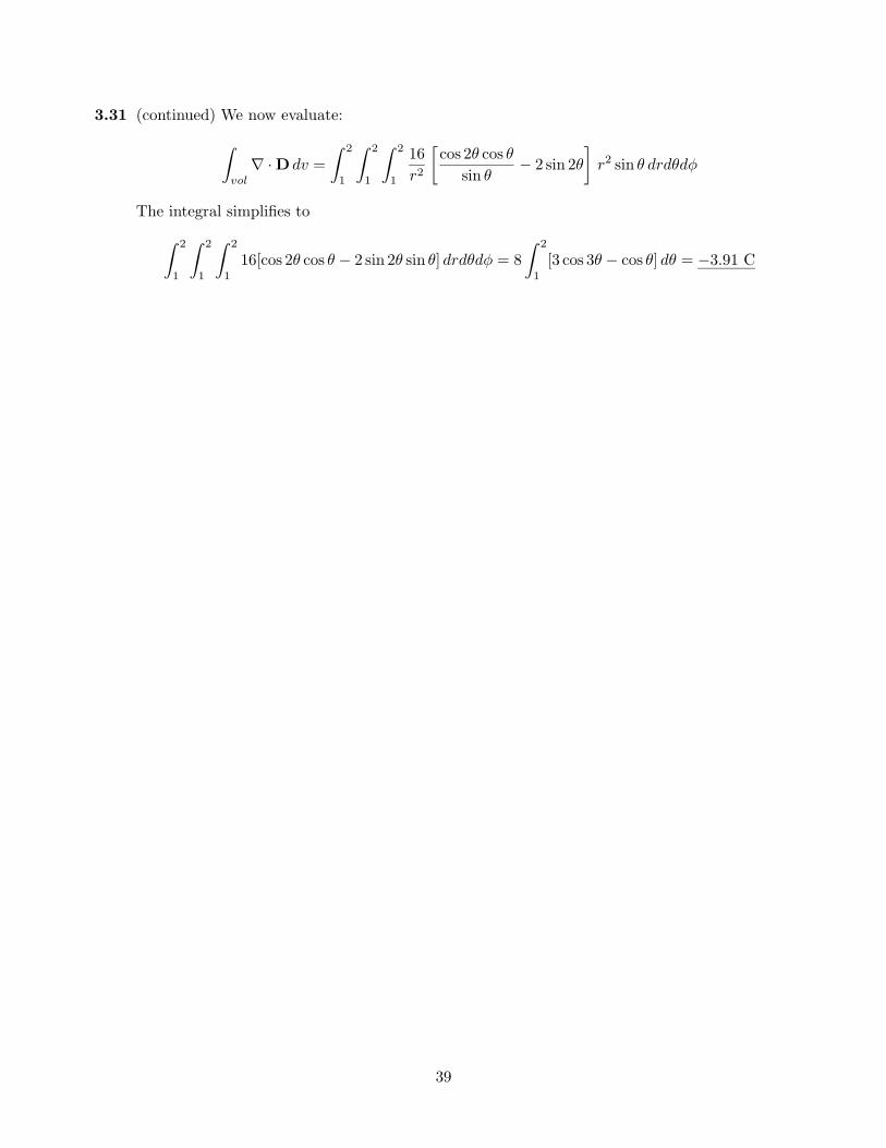
3.31 (continued) We now evaluate:
Z
vol∇ · D dv =
Z 2
1
Z 2
1
Z 2
1
16r2
∑cos 2θ cos θ
sin θ− 2 sin 2θ
∏r2 sin θ drdθdφ
The integral simplifies to
Z 2
1
Z 2
1
Z 2
116[cos 2θ cos θ − 2 sin 2θ sin θ] drdθdφ = 8
Z 2
1[3 cos 3θ − cos θ] dθ = −3.91 C
39
CHAPTER 4
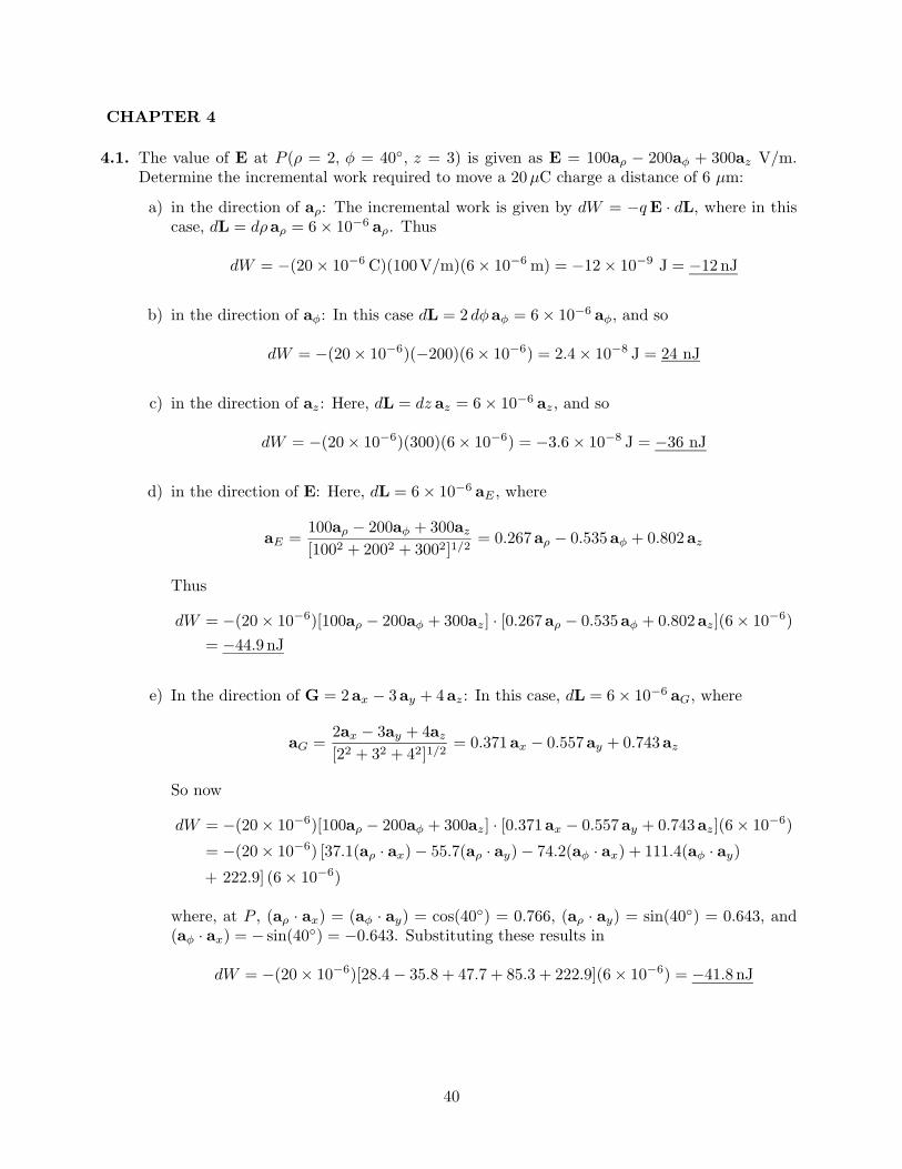
4.1. The value of E at P (ρ = 2, φ = 40, z = 3) is given as E = 100aρ − 200aφ + 300az V/m.Determine the incremental work required to move a 20µC charge a distance of 6 µm:
a) in the direction of aρ: The incremental work is given by dW = −q E · dL, where in thiscase, dL = dρaρ = 6× 10⁻⁶ aρ. Thus
dW = −(20× 10−6 C)(100V/m)(6× 10−6 m) = −12× 10−9 J = −12 nJ
b) in the direction of aφ: In this case dL = 2 dφaφ = 6× 10⁻⁶ aφ, and so
dW = −(20× 10−6)(−200)(6× 10⁻⁶) = 2.4× 10⁻⁸ J = 24 nJ
c) in the direction of az: Here, dL = dz az = 6× 10⁻⁶ az, and so
dW = −(20× 10−6)(300)(6× 10⁻⁶) = −3.6× 10⁻⁸ J = −36 nJ
d) in the direction of E: Here, dL = 6× 10⁻⁶ aE , where
aE =100aρ − 200aφ + 300az
[1002 + 2002 + 3002]1/2= 0.267aρ − 0.535aφ + 0.802az
Thus
dW = −(20× 10−6)[100aρ − 200aφ + 300az] · [0.267aρ − 0.535aφ + 0.802az](6× 10−6)= −44.9 nJ
e) In the direction of G = 2ax − 3ay + 4az: In this case, dL = 6× 10⁻⁶ aG, where
aG =2ax − 3ay + 4az
[22 + 32 + 42]1/2= 0.371ax − 0.557ay + 0.743az
So now
dW = −(20× 10−6)[100aρ − 200aφ + 300az] · [0.371ax − 0.557ay + 0.743az](6× 10−6)
= −(20× 10−6) [37.1(aρ · ax)− 55.7(aρ · ay)− 74.2(aφ · ax) + 111.4(aφ · ay)
+ 222.9] (6× 10⁻⁶)
where, at P , (aρ · ax) = (aφ · ay) = cos(40) = 0.766, (aρ · ay) = sin(40) = 0.643, and(aφ · ax) = − sin(40) = −0.643. Substituting these results in
dW = −(20× 10−6)[28.4− 35.8 + 47.7 + 85.3 + 222.9](6× 10−6) = −41.8 nJ
40
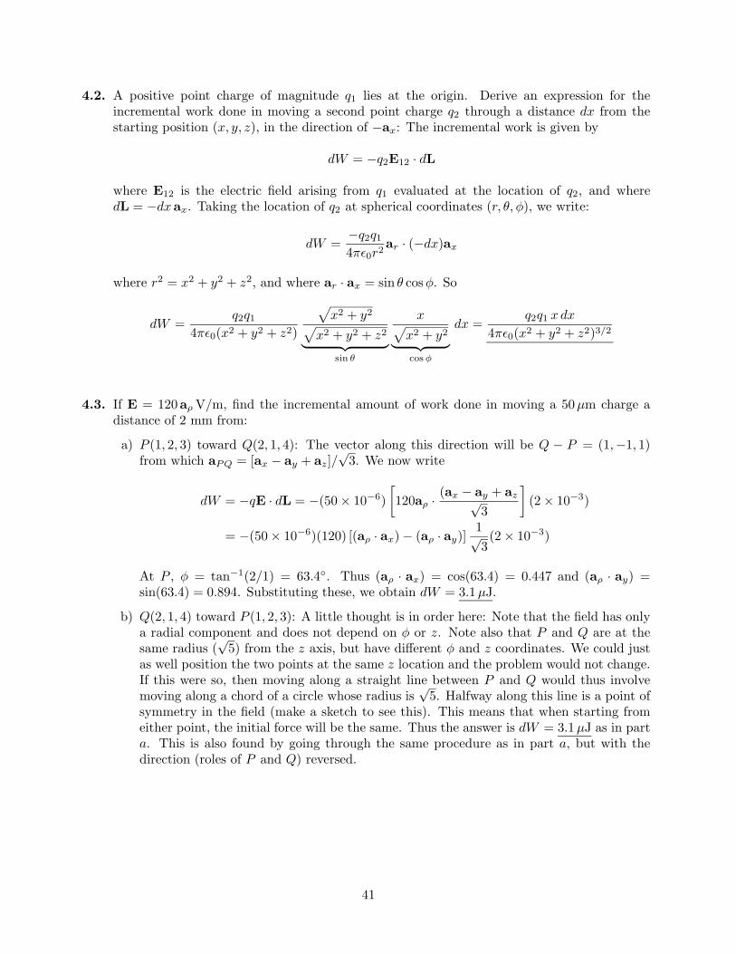
4.2. A positive point charge of magnitude q1 lies at the origin. Derive an expression for theincremental work done in moving a second point charge q2 through a distance dx from thestarting position (x, y, z), in the direction of −ax: The incremental work is given by
dW = −q2E12 · dL
where E12 is the electric field arising from q1 evaluated at the location of q2, and wheredL = −dxax. Taking the location of q2 at spherical coordinates (r, θ,φ), we write:
dW =−q2q1
4π≤0r2ar · (−dx)ax
where r2 = x2 + y2 + z2, and where ar · ax = sin θ cosφ. So
dW =q2q1
4π≤0(x2 + y2 + z2)
px2 + y2
px2 + y2 + z2
| z sin θ
xpx2 + y2
| z cos φ
dx =q2q1 xdx
4π≤0(x2 + y2 + z2)3/2
4.3. If E = 120aρ V/m, find the incremental amount of work done in moving a 50µm charge adistance of 2 mm from:
a) P (1, 2, 3) toward Q(2, 1, 4): The vector along this direction will be Q − P = (1,−1, 1)from which aPQ = [ax − ay + az]/
√3. We now write
dW = −qE · dL = −(50× 10−6)∑120aρ · (ax − ay + az√
3
∏(2× 10⁻³)
= −(50× 10−6)(120) [(aρ · ax)− (aρ · ay)]1√3(2× 10⁻³)
At P , φ = tan−1(2/1) = 63.4. Thus (aρ · ax) = cos(63.4) = 0.447 and (aρ · ay) =sin(63.4) = 0.894. Substituting these, we obtain dW = 3.1µJ.
b) Q(2, 1, 4) toward P (1, 2, 3): A little thought is in order here: Note that the field has onlya radial component and does not depend on φ or z. Note also that P and Q are at thesame radius (
√5) from the z axis, but have different φ and z coordinates. We could just
as well position the two points at the same z location and the problem would not change.If this were so, then moving along a straight line between P and Q would thus involvemoving along a chord of a circle whose radius is
√5. Halfway along this line is a point of
symmetry in the field (make a sketch to see this). This means that when starting fromeither point, the initial force will be the same. Thus the answer is dW = 3.1µJ as in parta. This is also found by going through the same procedure as in part a, but with thedirection (roles of P and Q) reversed.
41
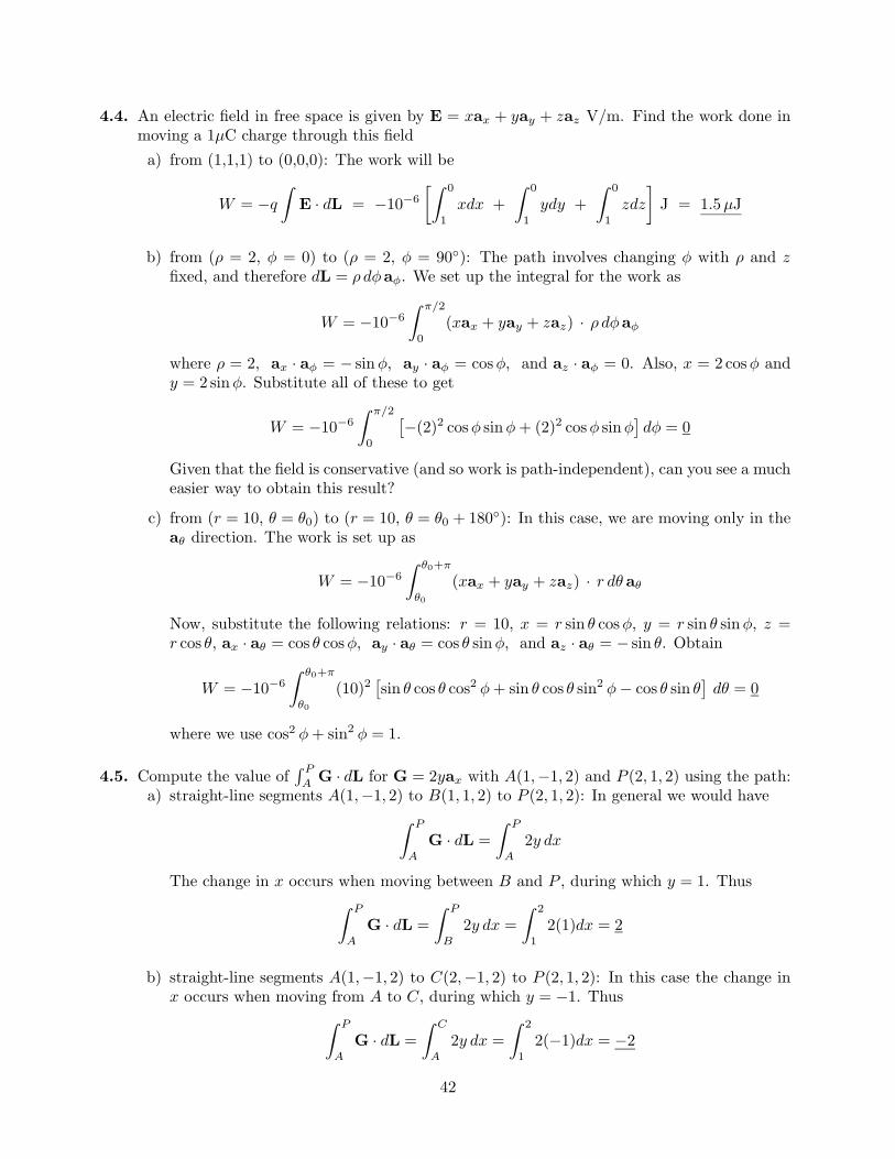
4.4. An electric field in free space is given by E = xax + yay + zaz V/m. Find the work done inmoving a 1µC charge through this fielda) from (1,1,1) to (0,0,0): The work will be
W = −q
ZE · dL = −10−6
∑Z 0
1xdx +
Z 0
1ydy +
Z 0
1zdz
∏J = 1.5µJ
b) from (ρ = 2, φ = 0) to (ρ = 2, φ = 90): The path involves changing φ with ρ and zfixed, and therefore dL = ρ dφaφ. We set up the integral for the work as
W = −10−6
Z π/2
0(xax + yay + zaz) · ρ dφaφ
where ρ = 2, ax · aφ = − sinφ, ay · aφ = cosφ, and az · aφ = 0. Also, x = 2 cosφ andy = 2 sinφ. Substitute all of these to get
W = −10−6
Z π/2
0
£−(2)2 cosφ sinφ + (2)2 cosφ sinφ
§dφ = 0
Given that the field is conservative (and so work is path-independent), can you see a mucheasier way to obtain this result?
c) from (r = 10, θ = θ0) to (r = 10, θ = θ0 + 180): In this case, we are moving only in theaθ direction. The work is set up as
W = −10−6
Z θ0+π
θ0
(xax + yay + zaz) · r dθ aθ
Now, substitute the following relations: r = 10, x = r sin θ cosφ, y = r sin θ sinφ, z =r cos θ, ax · aθ = cos θ cosφ, ay · aθ = cos θ sinφ, and az · aθ = − sin θ. Obtain
W = −10−6
Z θ0+π
θ0
(10)2£sin θ cos θ cos2 φ + sin θ cos θ sin2 φ− cos θ sin θ
§dθ = 0
where we use cos2 φ + sin2 φ = 1.
4.5. Compute the value ofR P
A G · dL for G = 2yax with A(1,−1, 2) and P (2, 1, 2) using the path:a) straight-line segments A(1,−1, 2) to B(1, 1, 2) to P (2, 1, 2): In general we would have
Z P
AG · dL =
Z P
A2y dx
The change in x occurs when moving between B and P , during which y = 1. ThusZ P
AG · dL =
Z P
B2y dx =
Z 2
12(1)dx = 2
b) straight-line segments A(1,−1, 2) to C(2,−1, 2) to P (2, 1, 2): In this case the change inx occurs when moving from A to C, during which y = −1. Thus
Z P
AG · dL =
Z C
A2y dx =
Z 2
12(−1)dx = −2
42
4.6. An electric field in free space is given as E = x ax + 4z ay + 4y az. Given V (1, 1, 1) = 10 V.Determine V (3, 3, 3). The potential difference is expressed as
V (3, 3, 3)− V (1, 1, 1) = −Z 3,3,3
1,1,1(x ax + 4z ay + 4y az) · (dxax + dy ay + dz az)
= −∑Z 3
1xdx +
Z 3
14z dy +
Z 3
14y dz
∏
We choose the following path: 1) move along x from 1 to 3; 2) move along y from 1 to 3,holding x at 3 and z at 1; 3) move along z from 1 to 3, holding x at 3 and y at 3. The integralsbecome:
V (3, 3, 3)− V (1, 1, 1) = −∑Z 3
1xdx +
Z 3
14(1) dy +
Z 3
14(3) dz
∏= −36
SoV (3, 3, 3) = −36 + V (1, 1, 1) = −36 + 10 = −26 V
4.7. Let G = 3xy3ax + 2zay. Given an initial point P (2, 1, 1) and a final point Q(4, 3, 1), findRG · dL using the path:a) straight line: y = x− 1, z = 1: We obtain:
ZG · dL =
Z 4
23xy2 dx +
Z 3
12z dy =
Z 4
23x(x− 1)2 dx +
Z 3
12(1) dy = 90
b) parabola: 6y = x2 + 2, z = 1: We obtain:Z
G · dL =Z 4
23xy2 dx +
Z 3
12z dy =
Z 4
2
112
x(x2 + 2)2 dx +Z 3
12(1) dy = 82
4.8. Given E = −xax+yay, a) find the work involved in moving a unit positive charge on a circulararc, the circle centered at the origin, from x = a to x = y = a/
√2.
In moving along the arc, we start at φ = 0 and move to φ = π/4. The setup is
W = −q
ZE · dL = −
Z π/4
0E · adφaφ = −
Z π/4
0(−x ax · aφ| z
− sin φ
+ y ay · aφ| z cos φ
)a dφ
= −Z π/4
02a2 sinφ cosφ dφ = −
Z π/4
0a2 sin(2φ) dφ =
a2
2cos(2φ)
ØØØπ/4
0= −a2
2
where q = 1, x = a cosφ, and y = a sinφ.
Note that the field is conservative, so we would get the same result by integrating alonga two-segment path over x and y as shown:
W = −Z
E · dL = −"Z a/
√2
a(−x) dx +
Z a/√
2
0y dy
#
= −a2/2
43
4.8b) Verify that the work done in moving the charge around the full circle from x = a is zero: Inthis case, the setup is the same, but the integration limits change:
W = −Z 2π
0a2 sin(2φ) dφ =
a2
2cos(2φ)
ØØØ2π
0= 0
4.9. A uniform surface charge density of 20 nC/m2 is present on the spherical surface r = 0.6 cmin free space.
a) Find the absolute potential at P (r = 1 cm, θ = 25, φ = 50): Since the charge densityis uniform and is spherically-symmetric, the angular coordinates do not matter. Thepotential function for r > 0.6 cm will be that of a point charge of Q = 4πa2ρs, or
V (r) =4π(0.6× 10⁻²)2(20× 10−9)
4π≤0r=
0.081r
V with r in meters
At r = 1 cm, this becomes V (r = 1 cm) = 8.14 V
b) Find VAB given points A(r = 2 cm, θ = 30, φ = 60) and B(r = 3 cm, θ = 45, φ = 90):Again, the angles do not matter because of the spherical symmetry. We use the part aresult to obtain
VAB = VA − VB = 0.081∑
10.02
− 10.03
∏= 1.36 V
4.10. A sphere of radius a carries a surface charge density of ρs0 C/m2.a) Find the absolute potential at the sphere surface: The setup for this is
V0 = −Z a
∞E · dL
where, from Gauss’ law:
E =a2ρs0
≤0r2ar V/m
SoV0 = −
Z a
∞
a2ρs0
≤0r2ar · ar dr =
a2ρs0
≤0r
ØØØa
∞=
aρs0
≤0V
b) A grounded conducting shell of radius b where b > a is now positioned around the chargedsphere. What is the potential at the inner sphere surface in this case? With the outersphere grounded, the field exists only between the surfaces, and is zero for r > b. Thepotential is then
V0 = −Z a
b
a2ρs0
≤0r2ar · ar dr =
a2ρs0
≤0r
ØØØa
b=
a2ρs0
≤0
∑1a− 1
b
∏V
44
4.11. Let a uniform surface charge density of 5 nC/m2 be present at the z = 0 plane, a uniform linecharge density of 8 nC/m be located at x = 0, z = 4, and a point charge of 2µC be presentat P (2, 0, 0). If V = 0 at M(0, 0, 5), find V at N(1, 2, 3): We need to find a potential functionfor the combined charges which is zero at M . That for the point charge we know to be
Vp(r) =Q
4π≤0r
Potential functions for the sheet and line charges can be found by taking indefinite integralsof the electric fields for those distributions. For the line charge, we have
Vl(ρ) = −Z
ρl
2π≤0ρdρ + C1 = − ρl
2π≤0ln(ρ) + C1
For the sheet charge, we have
Vs(z) = −Z
ρs
2≤0dz + C2 = − ρs
2≤0z + C2
The total potential function will be the sum of the three. Combining the integration constants,we obtain:
V =Q
4π≤0r− ρl
2π≤0ln(ρ)− ρs
2≤0z + C
The terms in this expression are not referenced to a common origin, since the charges are atdifferent positions. The parameters r, ρ, and z are scalar distances from the charges, and willbe treated as such here. To evaluate the constant, C, we first look at point M , where VT = 0.At M , r =
√22 + 52 =
√29, ρ = 1, and z = 5. We thus have
0 =2× 10⁻⁶
4π≤0√
29− 8× 10⁻⁹
2π≤0ln(1)− 5× 10⁻⁹
2≤05 + C ⇒ C = −1.93× 10³ V
At point N , r =√
1 + 4 + 9 =√
14, ρ =√
2, and z = 3. The potential at N is thus
VN =2× 10⁻⁶
4π≤0√
14− 8× 10⁻⁹
2π≤0ln(√
2)− 5× 10⁻⁹
2≤0(3)− 1.93× 103 = 1.98× 10³ V = 1.98 kV
45
4.12. In spherical coordinates, E = 2r/(r2 + a2)2 ar V/m. Find the potential at any point, usingthe referencea) V = 0 at infinity: We write in general
V (r) = −Z
2r dr
(r2 + a2)2+ C =
1r2 + a2
+ C
With a zero reference at r →∞, C = 0 and therefore V (r) = 1/(r2 + a2).b) V = 0 at r = 0: Using the general expression, we find
V (0) =1a2
+ C = 0 ⇒ C = − 1a2
Therefore
V (r) =1
r2 + a2− 1
a2=
−r2
a2(r2 + a2)
c) V = 100V at r = a: Here, we find
V (a) =1
2a2+ C = 100 ⇒ C = 100− 1
2a2
Therefore
V (r) =1
r2 + a2− 1
2a2+ 100 =
a2 − r2
2a2(r2 + a2)+ 100
4.13. Three identical point charges of 4 pC each are located at the corners of an equilateral triangle0.5 mm on a side in free space. How much work must be done to move one charge to a pointequidistant from the other two and on the line joining them? This will be the magnitude ofthe charge times the potential difference between the finishing and starting positions, or
W =(4× 10⁻¹²)2
2π≤0
∑1
2.5− 1
5
∏× 104 = 5.76× 10⁻¹⁰ J = 576pJ
4.14. Given the electric field E = (y + 1)ax + (x− 1)ay + 2az, find the potential difference betweenthe pointsa) (2,-2,-1) and (0,0,0): We choose a path along which motion occurs in one coordinate
direction at a time. Starting at the origin, first move along x from 0 to 2, where y = 0;then along y from 0 to −2, where x is 2; then along z from 0 to −1. The setup is
Vb − Va = −Z 2
0(y + 1)
ØØØy=0
dx −Z −2
0(x− 1)
ØØØx=2
dy −Z −1
02 dz = 2
b) (3,2,-1) and (-2,-3,4): Following similar reasoning,
Vb − Va = −Z 3
−2(y + 1)
ØØØy=−3
dx −Z 2
−3(x− 1)
ØØØx=3
dy −Z −1
42 dz = 10
46
4.15. Two uniform line charges, 8 nC/m each, are located at x = 1, z = 2, and at x = −1, y = 2in free space. If the potential at the origin is 100 V, find V at P (4, 1, 3): The net potentialfunction for the two charges would in general be:
V = − ρl
2π≤0ln(R1)−
ρl
2π≤0ln(R2) + C
At the origin, R1 = R2 =√
5, and V = 100 V. Thus, with ρl = 8× 10⁻⁹,
100 = −2(8× 10⁻⁹)
2π≤0ln(√
5) + C ⇒ C = 331.6 V
At P (4, 1, 3), R1 = |(4, 1, 3)−(1, 1, 2)| =√
10 and R2 = |(4, 1, 3)−(−1, 2, 3)| =√
26. Therefore
VP = −(8× 10⁻⁹)2π≤0
hln(√
10) + ln(√
26)i
+ 331.6 = −68.4 V
4.16. A spherically-symmetric charge distribution in free space (with a < r < ∞) – note typoin problem statement, which says (0 < r < ∞) – is known to have a potential functionV (r) = V0a2/r2, where V0 and a are constants.a) Find the electric field intensity: This is found through
E = −∇V = −dV
drar = 2V0
a2
r3ar V/m
b) Find the volume charge density: Use Maxwell’s first equation:
ρv = ∇ · D = ∇ · (≤0E) =1r2
d
dr
∑r2
µ2≤0V0
a2
r3
∂∏= −2≤0V0
a2
r4C/m3
c) Find the charge contained inside radius a: Here, we do not know the charge density insideradius a, but we do know the flux density at that radius. We use Gauss’ law to integrateD over the spherical surface at r = a to find the charge enclosed:
Qencl =I
r=aD · dS = 4πa2D|r=a = 4πa2
µ2≤0V0
a2
a3
∂= 8π≤0aV0 C
d) Find the total energy stored in the charge (or equivalently, in its electric field) in theregion (a < r <∞). We integrate the energy density in the field over the region:
We =Z
v
12D · E dv =
Z 2π
0
Z π
0
Z ∞
a2≤0V 2
0a4
r6r2 sin θ dr dθ dφ
= −8π V 20 ≤0 a4 1
3r3
ØØØ∞
a= 8π≤0aV 2
0 /3 J
47
4.17. Uniform surface charge densities of 6 and 2 nC/m2 are present at ρ = 2 and 6 cm respectively,in free space. Assume V = 0 at ρ = 4 cm, and calculate V at:
a) ρ = 5 cm: Since V = 0 at 4 cm, the potential at 5 cm will be the potential differencebetween points 5 and 4:
V5 = −Z 5
4E · dL = −
Z 5
4
aρsa
≤0ρdρ = −(.02)(6× 10⁻⁹)
≤0ln
µ54
∂= −3.026V
b) ρ = 7 cm: Here we integrate piecewise from ρ = 4 to ρ = 7:
V7 = −Z 6
4
aρsa
≤0ρdρ−
Z 7
6
(aρsa + bρsb)≤0ρ
dρ
With the given values, this becomes
V7 = −∑(.02)(6× 10⁻⁹)
≤0
∏ln
µ64
∂−
∑(.02)(6× 10⁻⁹) + (.06)(2× 10⁻⁹)
≤0
∏ln
µ76
∂
= −9.678V
4.18. Find the potential at the origin produced by a line charge ρL = kx/(x2 + a2) extending alongthe x axis from x = a to +∞, where a > 0. Assume a zero reference at infinity.
Think of the line charge as an array of point charges, each of charge dq = ρLdx, and eachhaving potential at the origin of dV = ρLdx/(4π≤0x). The total potential at the origin isthen the sum of all these potentials, or
V =Z ∞
a
ρL dx
4π≤0x=
Z ∞
a
k dx
4π≤0(x2 + a2)=
k
4π≤0atan−1
≥x
a
¥∞a
=k
4π≤0a
hπ
2− π
4
i=
k
16≤0a
4.19. The annular surface, 1 cm < ρ < 3 cm, z = 0, carries the nonuniform surface charge densityρs = 5ρnC/m2. Find V at P (0, 0, 2 cm) if V = 0 at infinity: We use the superposition integralform:
VP =Z Z
ρs da
4π≤0|r− r0|
where r = zaz and r0 = ρaρ. We integrate over the surface of the annular region, withda = ρ dρ dφ. Substituting the given values, we find
VP =Z 2π
0
Z .03
.01
(5× 10⁻⁹)ρ2 dρ dφ
4π≤0p
ρ2 + z2
Substituting z = .02, and using tables, the integral evaluates as
VP =∑(5× 10⁻⁹)
2≤0
∏ ∑ρ
2p
ρ2 + (.02)2 − (.02)2
2ln(ρ +
pρ2 + (.02)2)
∏.03
.01
= .081V
48
4.20. In a certain medium, the electric potential is given by
V (x) =ρ0
a≤0
°1− e−ax
¢
where ρ0 and a are constants.
a) Find the electric field intensity, E:
E == −∇V = − d
dx
∑ρ0
a≤0
°1− e−ax
¢∏ax = −ρ0
≤0e−ax ax V/m
b) find the potential difference between the points x = d and x = 0:
Vd0 = V (d)− V (0) =ρ0
a≤0
°1− e−ad
¢V
c) if the medium permittivity is given by ≤(x) = ≤0eax, find the electric flux density, D, andthe volume charge density, ρv, in the region:
D = ≤E = ≤0eax
µ−ρ0
≤0e−ax ax
∂= −ρ0 ax C/m2
Then ρv = ∇ · D = 0.d) Find the stored energy in the region (0 < x < d), (0 < y < 1), (0 < z < 1):
We =Z
v
12D · E dv =
Z 1
0
Z 1
0
Z d
0
ρ20
2≤0e−ax dx dy dz =
−ρ20
2≤0ae−ax
ØØØd
0=
ρ20
2≤0a°1− e−ad
¢J
4.21. Let V = 2xy2z3+3 ln(x2+2y2+3z2)V in free space. Evaluate each of the following quantitiesat P (3, 2,−1):
a) V : Substitute P directly to obtain: V = −15.0Vb) |V |. This will be just 15.0V.c) E: We have
EØØØP
= −∇VØØØP
= −∑µ
2y2z3 +6x
x2 + 2y2 + 3z2
∂ax +
µ4xyz3 +
12yx2 + 2y2 + 3z2
∂ay
+µ
6xy2z2 +18z
x2 + 2y2 + 3z2
∂az
∏
P
= 7.1ax + 22.8ay − 71.1az V/m
d) |E|P : taking the magnitude of the part c result, we find |E|P = 75.0V/m.
e) aN : By definition, this will be
aN
ØØØP
= − E|E| = −0.095ax − 0.304ay + 0.948az
f) D: This is DØØØP
= ≤0EØØØP
= 62.8ax + 202ay − 629az pC/m2.
49
4.22. A line charge of infinite length lies along the z axis, and carries a uniform linear charge densityof ρ` C/m. A perfectly-conducting cylindrical shell, whose axis is the z axis, surrounds theline charge. The cylinder (of radius b), is at ground potential. Under these conditions, thepotential function inside the cylinder (ρ < b) is given by
V (ρ) = k − ρ`
2π≤0ln(ρ)
where k is a constant.
a) Find k in terms of given or known parameters: At radius b,
V (b) = k − ρ`
2π≤0ln(b) = 0 ⇒ k =
ρ`
2π≤0ln(b)
b) find the electric field strength, E, for ρ < b:
Ein = −∇V = − d
dρ
∑ρ`
2π≤0ln(b)− ρ`
2π≤0ln(ρ)
∏aρ =
ρ`
2π≤0ρaρ V/m
c) find the electric field strength, E, for ρ > b: Eout = 0 because the cylinder is at groundpotential.
d) Find the stored energy in the electric field per unit length in the z direction within thevolume defined by ρ > a, where a < b:
We =Z
v
12D · E dv =
Z 1
0
Z 2π
0
Z b
a
ρ2`
8π2≤0ρ2ρ dρ dφ dz =
ρ2`
4π≤0ln
µb
a
∂J
4.23. It is known that the potential is given as V = 80ρ.6 V. Assuming free space conditions, find:
a) E: We find this through
E = −∇V = −dV
dρaρ = −48ρ−.4 V/m
b) the volume charge density at ρ = .5m: Using D = ≤0E, we find the charge densitythrough
ρv
ØØØ.5
= [∇ · D].5 =µ
1ρ
∂d
dρ(ρDρ)
ØØØ.5
= −28.8≤0ρ−1.4ØØØ.5
= −673 pC/m3
c) the total charge lying within the closed surface ρ = .6, 0 < z < 1: The easiest way to dothis calculation is to evaluate Dρ at ρ = .6 (noting that it is constant), and then multiplyby the cylinder area: Using part a, we have Dρ
ØØØ.6
= −48≤0(.6)−.4 = −521 pC/m2. Thus
Q = −2π(.6)(1)521× 10−12 C = −1.96 nC.
50
4.24. A certain spherically-symmetric charge configuration in free space produces an electric fieldgiven in spherical coordinates by:
E(r) =Ω
(ρ0r2)/(100≤0)ar V/m (r ≤ 10)(100ρ0)/(≤0r2)ar V/m (r ≥ 10)
where ρ0 is a constant.a) Find the charge density as a function of position:
ρv(r ≤ 10) = ∇ · (≤0E1) =1r2
d
dr
µr2 ρ0r2
100
∂=
ρ0r
25C/m3
ρv(r ≥ 10) = ∇ · (≤0E2) =1r2
d
dr
µr2 100ρ0
r2
∂= 0
b) find the absolute potential as a function of position in the two regions, r ≤ 10 and r ≥ 10:
V (r ≤ 10) = −Z 10
∞
100ρ0
≤0r2ar · ar dr −
Z r
10
ρ0(r0)2
100≤0ar · ar dr0
=100ρ0
≤0r
ØØØ10
∞− ρ0(r0)3
300≤0
ØØØr
10=
10ρ0
3≤0
£4− (10−3r3)
§V
V (r ≥ 10) = −Z r
∞
100ρ0
≤0(r0)2ar · ar dr0 =
100ρ0
≤0r0
ØØØr
∞=
100ρ0
≤0rV
c) check your result of part b by using the gradient:
E1 = −∇V (r ≤ 10) = − d
dr
∑10ρ0
3≤0
£4− (10−3r3)
§∏ar =
10ρ0
3≤0(3r2)(10−3)ar =
ρ0r2
100≤0ar
E2 = −∇V (r ≥ 10) = − d
dr
∑100ρ0
≤0r
∏ar =
100ρ0
≤0r2ar
d) find the stored energy in the charge by an integral of the form of Eq. (42) (not Eq. (43)):
We =12
Z
vρvV dv =
Z 2π
0
Z π
0
Z 10
0
12
ρ0r
25
∑10ρ0
3≤0
£4− (10−3r3)
§∏r2 sin θ dr dθ dφ
=4πρ2
0
150≤0
Z 10
0
∑40r3 − r6
100
∏dr =
4πρ20
150≤0
∑10r4 − r7
700
∏10
0
= 7.18× 10³ ρ20
≤0
e) Find the stored energy in the field by an integral of the form of Eq. (44) (not Eq. (45)).
We =Z
(r≤10)
12
D1 · E1 dv +Z
(r≥10)
12
D2 · E2 dv
=Z 2π
0
Z π
0
Z 10
0
ρ20r
4
(2× 10⁴)≤0r2 sin θ dr dθ dφ +
Z 2π
0
Z π
0
Z ∞
10
104ρ20
2≤0r4r2 sin θ dr dθ dφ
=2πρ2
0
≤0
∑10−4
Z 10
0r6 dr + 104
Z ∞
10
dr
r2
∏=
2πρ20
≤0
∑17(103) + 103
∏= 7.18× 10³ ρ2
0
≤0
51
4.25. Within the cylinder ρ = 2, 0 < z < 1, the potential is given by V = 100 + 50ρ + 150ρ sinφV.a) Find V , E, D, and ρv at P (1, 60, 0.5) in free space: First, substituting the given point,
we find VP = 279.9V. Then,
E = −∇V = −∂V
∂ρaρ −
1ρ
∂V
∂φaφ = − [50 + 150 sinφ]aρ − [150 cosφ]aφ
Evaluate the above at P to find EP = −179.9aρ − 75.0aφ V/m
Now D = ≤0E, so DP = −1.59aρ − .664aφ nC/m2. Then
ρv = ∇ ·D =µ
1ρ
∂d
dρ(ρDρ)+
1ρ
∂Dφ
∂φ=
∑−1
ρ(50 + 150 sinφ) +
1ρ150 sinφ
∏≤0 = −50
ρ≤0 C
At P , this is ρvP = −443 pC/m3.b) How much charge lies within the cylinder? We will integrate ρv over the volume to obtain:
Q =Z 1
0
Z 2π
0
Z 2
0−50≤0
ρρ dρ dφ dz = −2π(50)≤0(2) = −5.56 nC
4.26. Let us assume that we have a very thin, square, imperfectly conducting plate 2m on a side,located in the plane z = 0 with one corner at the origin such that it lies entirely within thefirst quadrant. The potential at any point in the plate is given as V = −e−x sin y.a) An electron enters the plate at x = 0, y = π/3 with zero initial velocity; in what direction
is its initial movement? We first find the electric field associated with the given potential:
E = −∇V = −e−x[sin y ax − cos y ay]
Since we have an electron, its motion is opposite that of the field, so the direction onentry is that of −E at (0,π/3), or
√3/2ax − 1/2ay.
b) Because of collisions with the particles in the plate, the electron achieves a relatively lowvelocity and little acceleration (the work that the field does on it is converted largely intoheat). The electron therefore moves approximately along a streamline. Where does itleave the plate and in what direction is it moving at the time? Considering the resultof part a, we would expect the exit to occur along the bottom edge of the plate. Theequation of the streamline is found through
Ey
Ex=
dy
dx= −cos y
sin y⇒ x = −
Ztan y dy + C = ln(cos y) + C
At the entry point (0,π/3), we have 0 = ln[cos(π/3)] + C, from which C = 0.69. Now,along the bottom edge (y = 0), we find x = 0.69, and so the exit point is (0.69, 0). Fromthe field expression evaluated at the exit point, we find the direction on exit to be −ay.
52
4.27. Two point charges, 1 nC at (0, 0, 0.1) and −1 nC at (0, 0,−0.1), are in free space.a) Calculate V at P (0.3, 0, 0.4): Use
VP =q
4π≤0|R+| −q
4π≤0|R−|
where R+ = (.3, 0, .3) and R− = (.3, 0, .5), so that |R+| = 0.424 and |R−| = 0.583. Thus
VP =10−9
4π≤0
∑1
.424− 1
.583
∏= 5.78V
b) Calculate |E| at P : Use
EP =q(.3ax + .3az)4π≤0(.424)3
− q(.3ax + .5az)4π≤0(.583)3
=10−9
4π≤0[2.42ax + 1.41az] V/m
Taking the magnitude of the above, we find |EP | = 25.2V/m.
c) Now treat the two charges as a dipole at the origin and find V at P : In spherical coor-dinates, P is located at r =
√.32 + .42 = .5 and θ = sin−1(.3/.5) = 36.9. Assuming a
dipole in far-field, we have
VP =qd cos θ
4π≤0r2=
10−9(.2) cos(36.9)4π≤0(.5)2
= 5.76V
4.28. Use the electric field intensity of the dipole (Sec. 4.7, Eq. (36)) to find the difference inpotential between points at θa and θb, each point having the same r and φ coordinates. Underwhat conditions does the answer agree with Eq. (34), for the potential at θa?
We perform a line integral of Eq. (36) along an arc of constant r and φ:
Vab = −Z θa
θb
qd
4π≤0r3[2 cos θ ar + sin θ aθ] · aθ r dθ = −
Z θa
θb
qd
4π≤0r2sin θ dθ
=qd
4π≤0r2[cos θa − cos θb]
This result agrees with Eq. (34) if θa (the ending point in the path) is 90 (the xy plane).Under this condition, we note that if θb > 90, positive work is done when moving (againstthe field) to the xy plane; if θb < 90, negative work is done since we move with the field.
4.29. A dipole having a moment p = 3ax−5ay +10az nC · m is located at Q(1, 2,−4) in free space.Find V at P (2, 3, 4): We use the general expression for the potential in the far field:
V =p · (r− r0)
4π≤0|r− r0|3
where r− r0 = P −Q = (1, 1, 8). So
VP =(3ax − 5ay + 10az) · (ax + ay + 8az)× 10−9
4π≤0[12 + 12 + 82]1.5= 1.31 V
53
4.30. A dipole for which p = 10≤0 az C · m is located at the origin. What is the equation of thesurface on which Ez = 0 but E 6= 0?
First we find the z component:
Ez = E · az =10
4πr3[2 cos θ (ar · az) + sin θ (aθ · az)] =
52πr3
£2 cos2 θ − sin2 θ
§
This will be zero when£2 cos2 θ − sin2 θ
§= 0. Using identities, we write
2 cos2 θ − sin2 θ =12[1 + 3 cos(2θ)]
The above becomes zero on the cone surfaces, θ = 54.7 and θ = 125.3.
4.31. A potential field in free space is expressed as V = 20/(xyz)V.
a) Find the total energy stored within the cube 1 < x, y, z < 2. We integrate the energydensity over the cube volume, where wE = (1/2)≤0E · E, and where
E = −∇V = 20∑
1x2yz
ax +1
xy2zay +
1xyz2
az
∏V/m
The energy is now
WE = 200≤0Z 2
1
Z 2
1
Z 2
1
∑1
x4y2z2+
1x2y4z2
+1
x2y2z4
∏dx dy dz
The integral evaluates as follows:
WE = 200≤0Z 2
1
Z 2
1
∑−
µ13
∂1
x3y2z2− 1
xy4z2− 1
xy2z4
∏2
1
dy dz
= 200≤0Z 2
1
Z 2
1
∑µ724
∂1
y2z2+
µ12
∂1
y4z2+
µ12
∂1
y2z4
∏dy dz
= 200≤0Z 2
1
∑−
µ724
∂1
yz2−
µ16
∂1
y3z2−
µ12
∂1
yz4
∏2
1
dz
= 200≤0Z 2
1
∑µ748
∂1z2
+µ
748
∂1z2
+µ
14
∂1z4
∏dz
= 200≤0(3)∑
796
∏= 387pJ
b) What value would be obtained by assuming a uniform energy density equal to the valueat the center of the cube? At C(1.5, 1.5, 1.5) the energy density is
wE = 200≤0(3)∑
1(1.5)4(1.5)2(1.5)2
∏= 2.07× 10⁻¹⁰ J/m3
This, multiplied by a cube volume of 1, produces an energy value of 207 pJ.
54
4.32. Using Eq. (36), a) find the energy stored in the dipole field in the region r > a:We start with
E(r, θ) =qd
4π≤0r3[2 cos θ ar + sin θ aθ]
Then the energy will be
We =Z
vol
12≤0E · E dv =
Z 2π
0
Z π
0
Z ∞
a
(qd)2
32π2≤0r6
£4 cos2 θ + sin2 θ
§| z
3 cos2 θ+1
r2 sin θ dr dθ dφ
=−2π(qd)2
32π2≤0
13r3
ØØØ∞
a
Z π
0
£3 cos2 θ + 1
§sin θ dθ =
(qd)2
48π2≤0a3
£− cos3 θ − cos θ
§π
0| z 4
=(qd)2
12π≤0a3J
b) Why can we not let a approach zero as a limit? From the above result, a singularity in theenergy occurs as a→ 0. More importantly, a cannot be too small, or the original far-fieldassumption used to derive Eq. (36) (a >> d) will not hold, and so the field expressionwill not be valid.
4.33. A copper sphere of radius 4 cm carries a uniformly-distributed total charge of 5µC in freespace.a) Use Gauss’ law to find D external to the sphere: with a spherical Gaussian surface at
radius r, D will be the total charge divided by the area of this sphere, and will be ar-directed. Thus
D =Q
4πr2ar =
5× 10⁻⁶
4πr2ar C/m2
b) Calculate the total energy stored in the electrostatic field: Use
WE =Z
vol
12D · E dv =
Z 2π
0
Z π
0
Z ∞
.04
12
(5× 10⁻⁶)2
16π2≤0r4r2 sin θ dr dθ dφ
= (4π)µ
12
∂(5× 10⁻⁶)2
16π2≤0
Z ∞
.04
dr
r2=
25× 10−12
8π≤0
1.04
= 2.81 J
c) Use WE = Q2/(2C) to calculate the capacitance of the isolated sphere: We have
C =Q2
2WE=
(5× 10⁻⁶)2
2(2.81)= 4.45× 10⁻¹² F = 4.45 pF
55
4.34. A sphere of radius a contains volume charge of uniform density ρ0 C/m3. Find the total storedenergy by applyinga) Eq. (43): We first need the potential everywhere inside the sphere. The electric field
inside and outside is readily found from Gauss’s law:
E1 =ρ0r
3≤0ar r ≤ a and E2 =
ρ0a3
3≤0r2ar r ≥ a
The potential at position r inside the sphere is now the work done in moving a unitpositive point charge from infinity to position r:
V (r) = −Z a
∞E2 · ar dr −
Z r
aE1 · ar dr0 = −
Z a
∞
ρ0a3
3≤0r2dr −
Z r
a
ρ0r0
3≤0dr0 =
ρ0
6≤0
°3a2 − r2
¢
Now, using this result in (43) leads to the energy associated with the charge in the sphere:
We =12
Z 2π
0
Z π
0
Z a
0
ρ20
6≤0
°3a2 − r2
¢r2 sin θ dr dθ dφ =
πρ0
3≤0
Z a
0
°3a2r2 − r4
¢dr =
4πa5ρ20
15≤0
b) Eq. (45): Using the given fields we find the energy densities
we1 =12≤0E1 · E1 =
ρ20r
2
18≤0r ≤ a and we2 =
12≤0E2 · E2 =
ρ20a
6
18≤0r4r ≥ a
We now integrate these over their respective volumes to find the total energy:
We =Z 2π
0
Z π
0
Z a
0
ρ20r
2
18≤0r2 sin θ dr dθ dφ +
Z 2π
0
Z π
0
Z ∞
a
ρ20a
6
18≤0r4r2 sin θ dr dθ dφ =
4πa5ρ20
15≤0
56
4.35. Four 0.8 nC point charges are located in free space at the corners of a square 4 cm on a side.a) Find the total potential energy stored: This will be given by
WE =12
4X
n=1
qnVn
where Vn in this case is the potential at the location of any one of the point charges thatarises from the other three. This will be (for charge 1)
V1 = V21 + V31 + V41 =q
4π≤0
∑1
.04+
1.04
+1
.04√
2
∏
Taking the summation produces a factor of 4, since the situation is the same at all fourpoints. Consequently,
WE =12(4)q1V1 =
(.8× 10−9)2
2π≤0(.04)
∑2 +
1√2
∏= 7.79× 10⁻⁷ J = 0.779µJ
b) A fifth 0.8 nC charge is installed at the center of the square. Again find the total storedenergy: This will be the energy found in part a plus the amount of work done in movingthe fifth charge into position from infinity. The latter is just the potential at the squarecenter arising from the original four charges, times the new charge value, or
∆WE =4(.8× 10−9)2
4π≤0(.04√
2/2)= .813µJ
The total energy is now
WE net = WE(part a) + ∆WE = .779 + .813 = 1.59µJ
4.36 Surface charge of uniform density ρs lies on a spherical shell of radius b, centered at the originin free space.a) Find the absolute potential everywhere, with zero reference at infinity: First, the electric
field, found from Gauss’ law, is
E =b2ρs
≤0r2ar V/m
ThenV (r) = −
Z r
∞E · dL = −
Z r
∞
b2ρs
≤0(r0)2dr0 =
b2ρs
≤0rV
b) find the stored energy in the sphere by considering the charge density and the potentialin a two-dimensional version of Eq. (42):
We =12
Z
SρsV (b) da =
12
Z 2π
0
Z π
0ρs
b2ρs
≤0bb2 sin θ dθ dφ =
2πρ2sb
3
≤0
c) find the stored energy in the electric field and show that the results of parts b and c areidentical.
We =Z
v
12
D · E dv =Z 2π
0
Z π
0
Z ∞
b
12
b4ρ2s
≤0r4r2 sin θ dr dθ dφ =
2πρ2sb
3
≤0
57
CHAPTER 5
5.1. Given the current density J = −104[sin(2x)e−2yax + cos(2x)e−2yay] kA/m2:
a) Find the total current crossing the plane y = 1 in the ay direction in the region 0 < x < 1,0 < z < 2: This is found through
I =Z Z
SJ · n
ØØØSda =
Z 2
0
Z 1
0J · ay
ØØØy=1
dx dz =Z 2
0
Z 1
0−104 cos(2x)e−2 dx dz
= −104(2)12
sin(2x)ØØØ1
0e−2 = −1.23MA
b) Find the total current leaving the region 0 < x, x < 1, 2 < z < 3 by integrating J ·dS overthe surface of the cube: Note first that current through the top and bottom surfaces willnot exist, since J has no z component. Also note that there will be no current through thex = 0 plane, since Jx = 0 there. Current will pass through the three remaining surfaces,and will be found through
I =Z 3
2
Z 1
0J · (−ay)
ØØØy=0
dx dz +Z 3
2
Z 1
0J · (ay)
ØØØy=1
dx dz +Z 3
2
Z 1
0J · (ax)
ØØØx=1
dy dz
= 104
Z 3
2
Z 1
0
£cos(2x)e−0 − cos(2x)e−2
§dx dz − 104
Z 3
2
Z 1
0sin(2)e−2y dy dz
= 104
µ12
∂sin(2x)
ØØØ1
0(3− 2)
£1− e−2
§+ 104
µ12
∂sin(2)e−2y
ØØØ1
0(3− 2) = 0
c) Repeat part b, but use the divergence theorem: We find the net outward current throughthe surface of the cube by integrating the divergence of J over the cube volume. We have
∇ · J =∂Jx
∂x+
∂Jy
∂y= −10−4
£2 cos(2x)e−2y − 2 cos(2x)e−2y
§= 0 as expected
5.2. Given J = −10−4(yax + xay)A/m2, find the current crossing the y = 0 plane in the −ay
direction between z = 0 and 1, and x = 0 and 2.
At y = 0, J(x, 0) = −104xay, so that the current through the plane becomes
I =Z
J · dS =Z 1
0
Z 2
0−104xay · (−ay) dx dz = 2× 10⁻⁴ A
58
5.3. LetJ =
400 sin θ
r2 + 4ar A/m2
a) Find the total current flowing through that portion of the spherical surface r = 0.8,bounded by 0.1π < θ < 0.3π, 0 < φ < 2π: This will be
I =Z Z
J · nØØØS
da =Z 2π
0
Z .3π
.1π
400 sin θ
(.8)2 + 4(.8)2 sin θ dθ dφ =
400(.8)22π4.64
Z .3π
.1πsin2 dθ
= 346.5Z .3π
.1π
12[1− cos(2θ)] dθ = 77.4A
b) Find the average value of J over the defined area. The area is
Area =Z 2π
0
Z .3π
.1π(.8)2 sin θ dθ dφ = 1.46m2
The average current density is thus Javg = (77.4/1.46)ar = 53.0ar A/m2.
5.4. If volume charge density is given as ρv = (cosωt)/r2 C/m3 in spherical coordinates, find J. Itis reasonable to assume that J is not a function of θ or φ.
We use the continuity equation (5), along with the assumption of no angular variation towrite
∇ · J =1r2
∂
∂r
°r2Jr
¢= −∂ρv
∂t= − ∂
∂t
µcosωt
r2
∂=
ω sinωt
r2
So we may now solve∂
∂r
°r2Jr
¢= ω sinωt
by direct integration to obtain:
J = Jr ar =ω sinωt
rar A/m2
where the integration constant is set to zero because a steady current will not be createdby a time-varying charge density.
59
5.5. LetJ =
25ρ
aρ −20
ρ2 + 0.01az A/m2
a) Find the total current crossing the plane z = 0.2 in the az direction for ρ < 0.4: Use
I =Z Z
SJ · n
ØØØz=.2
da =Z 2π
0
Z .4
0
−20ρ2 + .01
ρ dρ dφ
= −µ
12
∂20 ln(.01 + ρ2)
ØØØ.4
0(2π) = −20π ln(17) = −178.0A
b) Calculate ∂ρv/∂t: This is found using the equation of continuity:
∂ρv
∂t= −∇ · J =
1ρ
∂
∂ρ(ρJρ) +
∂Jz
∂z=
1ρ
∂
∂ρ(25) +
∂
∂z
µ−20
ρ2 + .01
∂= 0
c) Find the outward current crossing the closed surface defined by ρ = 0.01, ρ = 0.4, z = 0,and z = 0.2: This will be
I =Z .2
0
Z 2π
0
25.01
aρ · (−aρ)(.01) dφ dz +Z .2
0
Z 2π
0
25.4
aρ · (aρ)(.4) dφ dz
+Z 2π
0
Z .4
0
−20ρ2 + .01
az · (−az) ρ dρ dφ +Z 2π
0
Z .4
0
−20ρ2 + .01
az · (az) ρ dρ dφ = 0
since the integrals will cancel each other.
d) Show that the divergence theorem is satisfied for J and the surface specified in part b.In part c, the net outward flux was found to be zero, and in part b, the divergence of Jwas found to be zero (as will be its volume integral). Therefore, the divergence theoremis satisfied.
5.6. In spherical coordinates, a current density J = −k/(r sin θ)aθ A/m2 exists in a conductingmedium, where k is a constant. Determine the total current in the az direction that crosses acircular disk of radius R, centered on the z axis and located at a) z = 0; b) z = h.
Integration over a disk means that we use cylindrical coordinates. The general flux integralassumes the form:
I =Z
sJ · dS =
Z 2π
0
Z R
0
−k
r sin θaθ · az| z − sin θ
ρ dρ dφ
Then, using r =p
ρ2 + z2, this becomes
I =Z 2π
0
Z R
0
kρpρ2 + z2
= 2πkp
ρ2 + z2ØØØR
0= 2πk
hpR2 + z2 − z
i
At z = 0 (part a), we have I(0) = 2πkR , and at z = h (part b): I(h) = 2πk£√
R2 + h2 − h§.
60
5.7. Assuming that there is no transformation of mass to energy or vice-versa, it is possible towrite a continuity equation for mass.
a) If we use the continuity equation for charge as our model, what quantities correspond to Jand ρv? These would be, respectively, mass flux density in (kg/m2 − s) and mass densityin (kg/m3).
b) Given a cube 1 cm on a side, experimental data show that the rates at which mass isleaving each of the six faces are 10.25, -9.85, 1.75, -2.00, -4.05, and 4.45 mg/s. If weassume that the cube is an incremental volume element, determine an approximate valuefor the time rate of change of density at its center. We may write the continuity equationfor mass as follows, also invoking the divergence theorem:
Z
v
∂ρm
∂tdv = −
Z
v∇ · Jm dv = −
I
sJm · dS
where I
sJm · dS = 10.25− 9.85 + 1.75− 2.00− 4.05 + 4.45 = 0.550 mg/s
Treating our 1 cm3 volume as differential, we find
∂ρm
∂t.= −0.550× 10⁻³ g/s
10−6 m3= −550 g/m3 − s
5.8. A truncated cone has a height of 16 cm. The circular faces on the top and bottom have radiiof 2mm and 0.1mm, respectively. If the material from which this solid cone is constructedhas a conductivity of 2× 10⁶ S/m, use some good approximations to determine the resistancebetween the two circular faces.
Consider the cone upside down and centered on the positive z axis. The 1-mm radius endis at distance z = ` from the x-y plane; the wide end (2-mm radius) lies at z = `+16 cm.` is chosen such that if the cone were not truncated, its vertex would occur at the origin.The cone surface subtends angle θc from the z axis (in spherical coordinates). Therefore,we may write
` =0.1mmtan θc
and tan θc =2mm
160 + `
Solving these, we find ` = 8.4 mm, tan θc = 1.19× 10⁻², and so θc = 0.68, which givesus a very thin cone! With this understanding, we can assume that the current density isuniform with θ and φ and will vary only with spherical radius, r. So the current densitywill be constant over a spherical cap (of constant r) anywhere within the cone. As thecone is thin, we can also assume constant current density over any flat surface within thecone at a specifed z. That is, any spherical cap looks flat if the cap radius, r, is largecompared to its radius as measured from the z axis (ρ). This is our primary assumption.
Now, assuming constant current density at constant r, and net current, I, we may write
I =Z 2π
0
Z θc
0J(r)ar · ar r2 sin θ dθ dφ = 2πr2J(r)(1− cos θc)
orJ(r) =
I
2πr2(1− cos θc)ar =
(1.42× 10⁴)I2πr2
ar
61
5.8 (continued) The electric field is now
E(r) =J(r)σ
=(1.42× 10⁴)I2πr2(2× 10⁶)
ar = (7.1× 10⁻³)I
2πr2ar V/m
The voltage between the ends is now
V0 = −Z rin
rout
E · ar dr
where rin = `/ cos θc.= ` and where rout = (160 + `)/ cos θc
.= 160 + `. The voltage is
V0 = −Z `×10−3
(160+`)×10−3(7.1× 10⁻³)
I
2πr2ar · ar dr = (7.1× 10⁻³)
I
2π
∑1
.0084− 1
.1684
∏
=0.40π
I
from which we identify the resistance as R = 0.40/π = 0.128 ohms.
A second method uses the idea that we can construct the cone from a stack of thin circularplates of linearly-increasing radius, ρ. Assuming each plate is of differential thickness, dz,the differential resistance of a plate will be
dR =dz
σπρ2
where ρ = z tan θc = z(1.19 × 10⁻²). The cone resistance will be the resistance of thestack of plates (in series), found through
R =Z
dR =Z (160+`)×10−3
`×10−3
dz
σπρ2=
Z (160+`)×10−3
`×10−3
dz
(2× 10⁶)πz2(1.19× 10⁻²)2
=3.53× 10⁻³
π
∑1
.0084− 1
.1684
∏= 0.127 ohms
5.9. a) Using data tabulated in Appendix C, calculate the required diameter for a 2-m long nichromewire that will dissipate an average power of 450 W when 120 V rms at 60 Hz is applied to it:
The required resistance will be
R =V 2
P=
l
σ(πa2)
Thus the diameter will be
d = 2a = 2r
lP
σπV 2= 2
s2(450)
(106)π(120)2= 2.8× 10⁻⁴ m = 0.28mm
b) Calculate the rms current density in the wire: The rms current will be I = 450/120 =3.75A. Thus
J =3.75
π (2.8× 10⁻⁴/2)2= 6.0× 10⁷ A/m2
62
5.10. A large brass washer has a 2-cm inside diameter, a 5-cm outside diameter, and is 0.5 cm thick.Its conductivity is σ = 1.5 × 10⁷ S/m. The washer is cut in half along a diameter, and avoltage is applied between the two rectangular faces of one part. The resultant electric fieldin the interior of the half-washer is E = (0.5/ρ)aφ V/m in cylindrical coordinates, where thez axis is the axis of the washer.a) What potential difference exists between the two rectangular faces? First, we orient the
washer in the x-y plane with the cut faces aligned with the x axis. To find the voltage,we integrate E over a circular path of radius ρ inside the washer, between the two cutfaces:
V0 = −Z
E · dL = −Z 0
π
0.5πρ
aφ · aφ ρ dφ = 0.5π V
b) What total current is flowing? First, the current density is J = σE, so
J =1.5× 10⁷(0.5)
ρaφ =
7.5× 10⁶
ρaφ A/m2
Current is then found by integrating J over any transverse plane in the washer (therectangular cross-section):
I =Z
sJ · dS =
Z 0.5×10⁻²
0
Z 2.5×10⁻²
10−2
7.5× 10⁶
ρaφ · aφ dρ dz
= 0.5× 10⁻²(7.5× 10⁶) lnµ
2.51
∂= 3.4× 10⁴ A
c) What is the resistance between the two faces?
R =V0
I=
0.5π3.4× 104
= 4.6× 10⁻⁵ ohms
5.11. Two perfectly-conducting cylindrical surfaces of length l are located at ρ = 3 and ρ = 5 cm.The total current passing radially outward through the medium between the cylinders is 3 Adc.a) Find the voltage and resistance between the cylinders, and E in the region between the
cylinders, if a conducting material having σ = 0.05 S/m is present for 3 < ρ < 5 cm:Given the current, and knowing that it is radially-directed, we find the current densityby dividing it by the area of a cylinder of radius ρ and length l:
J =3
2πρlaρ A/m2
63
5.11a) (continued)Then the electric field is found by dividing this result by σ:
E =3
2πσρlaρ =
9.55ρl
aρ V/m
The voltage between cylinders is now:
V = −Z 3
5E · dL =
Z 5
3
9.55ρl
aρ · aρdρ =9.55
lln
µ53
∂=
4.88l
V
Now, the resistance will be
R =V
I=
4.883l
=1.63
lΩ
b) Show that integrating the power dissipated per unit volume over the volume gives thetotal dissipated power: We calculate
P =Z
vE · J dv =
Z l
0
Z 2π
0
Z .05
.03
32
(2π)2ρ2(.05)l2ρ dρ dφ dz =
32
2π(.05)lln
µ53
∂=
14.64l
W
We also find the power by taking the product of voltage and current:
P = V I =4.88
l(3) =
14.64l
W
which is in agreement with the power density integration.
5.12. Two identical conducting plates, each having area A, are located at z = 0 and z = d. The re-gion between plates is filled with a material having z-dependent conductivity, σ(z) = σ0e−z/d,where σ0 is a constant. Voltage V0 is applied to the plate at z = d; the plate at z = 0 is atzero potential. Find, in terms of the given parameters:a) the resistance of the material: We start with the differential resistance of a thin slab of
the material of thickness dz, which is
dR =dz
σA=
ez/ddz
σ0Aso that R =
ZdR =
Z d
0
ez/ddz
σ0A=
d
σ0A(e− 1) =
1.72dσ0A
Ω
b) the total current flowing between plates: We use
I =V0
R=
σ0AV0
1.72 d
c) the electric field intensity E within the material: First the current density is
J = − I
Aaz =
−σ0V0
1.72 daz so that E =
Jσ(z)
=−V0ez/d
1.72 daz V/m
64
5.13. A hollow cylindrical tube with a rectangular cross-section has external dimensions of 0.5 in by1 in and a wall thickness of 0.05 in. Assume that the material is brass, for which σ = 1.5×10⁷
S/m. A current of 200 A dc is flowing down the tube.
a) What voltage drop is present across a 1m length of the tube? Converting all measurementsto meters, the tube resistance over a 1 m length will be:
R1 =1
(1.5× 10⁷) [(2.54)(2.54/2)× 10−4 − 2.54(1− .1)(2.54/2)(1− .2)× 10−4]= 7.38× 10⁻⁴ Ω
The voltage drop is now V = IR1 = 200(7.38× 10−4 = 0.147 V.
b) Find the voltage drop if the interior of the tube is filled with a conducting material forwhich σ = 1.5× 10⁵ S/m: The resistance of the filling will be:
R2 =1
(1.5× 10⁵)(1/2)(2.54)2 × 10−4(.9)(.8)= 2.87× 10⁻² Ω
The total resistance is now the parallel combination of R1 and R2:RT = R1R2/(R1 + R2) = 7.19×10⁻⁴ Ω, and the voltage drop is now V = 200RT = .144V.
5.14. A rectangular conducting plate lies in the xy plane, occupying the region 0 < x < a, 0 < y < b.An identical conducting plate is positioned directly above and parallel to the first, at z = d.The region between plates is filled with material having conductivity σ(x) = σ0e−x/a, whereσ0 is a constant. Voltage V0 is applied to the plate at z = d; the plate at z = 0 is at zeropotential. Find, in terms of the given parameters:a) the electric field intensity E within the material: We know that E will be z-directed,
but the conductivity varies with x. We therefore expect no z variation in E, and alsonote that the line integral of E between the bottom and top plates must always give V0.Therefore E = −V0/daz V/m.
b) the total current flowing between plates: We have
J = σ(x)E =−σ0e−x/aV0
daz
Using this, we find
I =Z
J · dS =Z b
0
Z a
0
−σ0e−x/aV0
daz · (−az) dx dy =
σ0abV0
d(1− e−1) =
0.63abσ0V0
dA
c) the resistance of the material: We use
R =V0
I=
d
0.63 abσ0Ω
65
5.15. Let V = 10(ρ + 1)z2 cosφV in free space.
a) Let the equipotential surface V = 20V define a conductor surface. Find the equation ofthe conductor surface: Set the given potential function equal to 20, to find:
(ρ + 1)z2 cosφ = 2
b) Find ρ and E at that point on the conductor surface where φ = 0.2π and z = 1.5: Atthe given values of φ and z, we solve the equation of the surface found in part a for ρ,obtaining ρ = .10. Then
E = −∇V = −∂V
∂ρaρ −
1ρ
∂V
∂φaφ −
∂V
∂zaz
= −10z2 cosφaρ + 10ρ + 1
ρz2 sinφaφ − 20(ρ + 1)z cosφaz
ThenE(.10, .2π, 1.5) = −18.2aρ + 145aφ − 26.7az V/m
c) Find |ρs| at that point: Since E is at the perfectly-conducting surface, it will be normalto the surface, so we may write:
ρs = ≤0E ·nØØØsurface
= ≤0E · E|E| = ≤0
√E · E = ≤0
p(18.2)2 + (145)2 + (26.7)2 = 1.32 nC/m2
5.16. A coaxial transmission line has inner and outer conductor radii a and b. Between conductors(a < ρ < b) lies a conductive medium whose conductivity is σ(ρ) = σ0/ρ, where σ0 is aconstant. The inner conductor is charged to potential V0, and the outer conductor is grounded.
a) Assuming dc radial current I per unit length in z, determine the radial current densityfield J in A/m2: This will be the current divided by the cross-sectional area that is normalto the current direction:
J =I
2πρ(1)aρ A/m2
b) Determine the electric field intensity E in terms of I and other parameters, given orknown:
E =Jσ
=Iρ
2πσ0ρaρ =
I
2πσ0aρ V/m
c) by taking an appropriate line integral of E as found in part b, find an expression thatrelates V0 to I:
V0 = −Z a
bE · dL = −
Z a
b
I
2πσ0aρ · aρ dρ =
I(b− a)2πσ0
V
d) find an expression for the conductance of the line per unit length, G:
G =I
V0=
2πσ0
(b− a)S/m
66
5.17. Given the potential field V = 100xz/(x2 + 4) V. in free space:a) Find D at the surface z = 0: Use
E = −∇V = −100z∂
∂x
µx
x2 + 4
∂ax − 0ay −
100xx2 + 4
az V/m
At z = 0, we use this to find D(z = 0) = ≤0E(z = 0) = −100≤0x/(x2 + 4)az C/m2.
b) Show that the z = 0 surface is an equipotential surface: There are two reasons for this:1) E at z = 0 is everywhere z-directed, and so moving a charge around on the surfaceinvolves doing no work; 2) When evaluating the given potential function at z = 0, theresult is 0 for all x and y.
c) Assume that the z = 0 surface is a conductor and find the total charge on that portionof the conductor defined by 0 < x < 2, −3 < y < 0: We have
ρs = D · az
ØØØz=0
= −100≤0xx2 + 4
C/m2
So
Q =Z 0
−3
Z 2
0−100≤0x
x2 + 4dx dy = −(3)(100)≤0
µ12
∂ln(x2 + 4)
ØØØ2
0= −150≤0 ln 2 = −0.92 nC
5.18. Two parallel circular plates of radius a are located at z = 0 and z = d. The top plate (z = d)is raised to potential V0; the bottom plate is grounded. Between the plates is a conductingmaterial having radial-dependent conductivity, σ(ρ) = σ0ρ, where σ0 is a constant.
a) Find the ρ-independent electric field strength, E, between plates: The integral of E be-tween plates must give V0, independent of position on the plates. Therefore, it must betrue that
E = −V0
daz V/m (0 < ρ < a)
b) Find the current density, J between plates:
J = σE = −σ0V0ρ
daz A/m2
c) Find the total current, I, in the structure:
I =Z 2π
0
Z a
0−σ0V0ρ
daz · (−az) ρ dρ dφ =
2πa3σ0V0
3dA
d) Find the resistance between plates:
R =V0
I=
3d2πa3σ0
ohms
67
5.19. Let V = 20x2yz − 10z2 V in free space.
a) Determine the equations of the equipotential surfaces on which V = 0 and 60 V: Setting thegiven potential function equal to 0 and 60 and simplifying results in:
At 0V : 2x2y − z = 0
At 60V : 2x2y − z =6z
b) Assume these are conducting surfaces and find the surface charge density at that pointon the V = 60 V surface where x = 2 and z = 1. It is known that 0 ≤ V ≤ 60 V is thefield-containing region: First, on the 60 V surface, we have
2x2y − z − 6z
= 0 ⇒ 2(2)2y(1)− 1− 6 = 0 ⇒ y =78
NowE = −∇V = −40xyz ax − 20x2z ay − [20xy − 20z]az
Then, at the given point, we have
D(2, 7/8, 1) = ≤0E(2, 7/8, 1) = −≤0[70ax + 80ay + 50az] C/m2
We know that since this is the higher potential surface, D must be directed away fromit, and so the charge density would be positive. Thus
ρs =√
D · D = 10≤0p
72 + 82 + 52 = 1.04 nC/m2
c) Give the unit vector at this point that is normal to the conducting surface and directedtoward the V = 0 surface: This will be in the direction of E and D as found in part b, or
an = −∑7ax + 8ay + 5az√
72 + 82 + 52
∏= −[0.60ax + 0.68ay + 0.43az]
5.20. Two point charges of −100π µC are located at (2,-1,0) and (2,1,0). The surface x = 0 is aconducting plane.a) Determine the surface charge density at the origin. I will solve the general case first, in
which we find the charge density anywhere on the y axis. With the conducting plane inthe yz plane, we will have two image charges, each of +100π µC, located at (-2, -1, 0)and (-2, 1, 0). The electric flux density on the y axis from these four charges will be
D(y) =−100π
4π
[(y − 1)ay − 2ax][(y − 1)2 + 4]3/2
+[(y + 1)ay − 2ax][(y + 1)2 + 4]3/2
| z given charges
− [(y − 1)ay + 2ax][(y − 1)2 + 4]3/2
− [(y + 1)ay + 2ax][(y + 1)2 + 4]3/2
| z image charges
µC/m2
68
5.20 a) (continued)In the expression, all y components cancel, and we are left with
D(y) = 100∑
1[(y − 1)2 + 4]3/2
+1
[(y + 1)2 + 4]3/2
∏ax µC/m2
We now find the charge density at the origin:
ρs(0, 0, 0) = D · ax
ØØØy=0
= 17.9 µC/m2
b) Determine ρS at P (0, h, 0). This will be
ρs(0, h, 0) = D · ax
ØØØy=h
= 100∑
1[(h− 1)2 + 4]3/2
+1
[(h + 1)2 + 4]3/2
∏µC/m2
5.21. Let the surface y = 0 be a perfect conductor in free space. Two uniform infinite line chargesof 30 nC/m each are located at x = 0, y = 1, and x = 0, y = 2.a) Let V = 0 at the plane y = 0, and find V at P (1, 2, 0): The line charges will image across
the plane, producing image line charges of -30 nC/m each at x = 0, y = −1, and x = 0,y = −2. We find the potential at P by evaluating the work done in moving a unit positivecharge from the y = 0 plane (we choose the origin) to P : For each line charge, this willbe:
VP − V0,0,0 = − ρl
2π≤0ln
∑final distance from chargeinitial distance from charge
∏
where V0,0,0 = 0. Considering the four charges, we thus have
VP = − ρl
2π≤0
"
lnµ
12
∂+ ln
√√2
1
!
− ln
√√101
!
− ln
√√172
!#
=ρl
2π≤0
"
ln (2) + lnµ
1√2
∂+ ln
≥√10
¥+ ln
√√172
!#
=30× 10−9
2π≤0ln
"√10√
17√2
#
= 1.20 kV
b) Find E at P : Use
EP =ρl
2π≤0
∑(1, 2, 0)− (0, 1, 0)
|(1, 1, 0)|2 +(1, 2, 0)− (0, 2, 0)
|(1, 0, 0)|2
− (1, 2, 0)− (0,−1, 0)|(1, 3, 0)|2 − (1, 2, 0)− (0,−2, 0)
|(1, 4, 0)|2
∏
=ρl
2π≤0
∑(1, 1, 0)
2+
(1, 0, 0)1
− (1, 3, 0)10
− (1, 4, 0)17
∏= 723ax − 18.9ay V/m
69
5.22. The line segment x = 0, −1 ≤ y ≤ 1, z = 1, carries a linear charge density ρL = π|y| µC/m.Let z = 0 be a conducting plane and determine the surface charge density at: (a) (0,0,0); (b)(0,1,0).
We consider the line charge to be made up of a string of differential segments of length, dy0,and of charge dq = ρL dy0. A given segment at location (0, y0, 1) will have a correspondingimage charge segment at location (0, y0,−1). The differential flux density on the y axisthat is associated with the segment-image pair will be
dD =ρL dy0[(y − y0)ay − az]
4π[(y − y0)2 + 1]3/2− ρL dy0[(y − y0)ay + az]
4π[(y − y0)2 + 1]3/2=
−ρL dy0 az
2π[(y − y0)2 + 1]3/2
In other words, each charge segment and its image produce a net field in which the ycomponents have cancelled. The total flux density from the line charge and its image isnow
D(y) =Z
dD =Z 1
−1
−π|y0|az dy0
2π[(y − y0)2 + 1]3/2
= −az
2
Z 1
0
∑y0
[(y − y0)2 + 1]3/2+
y0
[(y + y0)2 + 1]3/2
∏dy0
=az
2
∑y(y − y0) + 1
[(y − y0)2 + 1]1/2+
y(y + y0) + 1[(y + y0)2 + 1]1/2
∏1
0
=az
2
∑y(y − 1) + 1
[(y − 1)2 + 1]1/2+
y(y + 1) + 1[(y + 1)2 + 1]1/2
− 2(y2 + 1)1/2
∏
Now, at the origin (part a), we find the charge density through
ρs(0, 0, 0) = D · az
ØØØy=0
=az
2
∑1√2
+1√2− 2
∏= −0.29 µC/m2
Then, at (0,1,0) (part b), the charge density is
ρs(0, 1, 0) = D · az
ØØØy=1
=az
2
∑1 +
3√5− 2
∏= −0.24 µC/m2
5.23. A dipole with p = 0.1az µC · m is located at A(1, 0, 0) in free space, and the x = 0 plane isperfectly-conducting.
a) Find V at P (2, 0, 1). We use the far-field potential for a z-directed dipole:
V =p cos θ
4π≤0r2=
p
4π≤0
z
[x2 + y2 + z2]1.5
The dipole at x = 1 will image in the plane to produce a second dipole of the oppositeorientation at x = −1. The potential at any point is now:
V =p
4π≤0
∑z
[(x− 1)2 + y2 + z2]1.5− z
[(x + 1)2 + y2 + z2]1.5
∏
Substituting P (2, 0, 1), we find
V =.1× 106
4π≤0
∑1
2√
2− 1
10√
10
∏= 289.5 V
70
5.23 b) Find the equation of the 200-V equipotential surface in cartesian coordinates: We just set thepotential exression of part a equal to 200 V to obtain:
∑z
[(x− 1)2 + y2 + z2]1.5− z
[(x + 1)2 + y2 + z2]1.5
∏= 0.222
5.24. At a certain temperature, the electron and hole mobilities in intrinsic germanium are given as0.43 and 0.21 m2/V · s, respectively. If the electron and hole concentrations are both 2.3×10¹⁹
m−3, find the conductivity at this temperature.With the electron and hole charge magnitude of 1.6 × 10⁻¹⁹ C, the conductivity in thiscase can be written:
σ = |ρe|µe + ρhµh = (1.6× 10⁻¹⁹)(2.3× 10¹⁹)(0.43 + 0.21) = 2.36 S/m
5.25. Electron and hole concentrations increase with temperature. For pure silicon, suitable expres-sions are ρh = −ρe = 6200T 1.5e−7000/T C/m3. The functional dependence of the mobilitieson temperature is given by µh = 2.3 × 10⁵T−2.7 m2/V · s and µe = 2.1 × 10⁵T−2.5 m2/V · s,where the temperature, T , is in degrees Kelvin. The conductivity will thus be
σ = −ρeµe + ρhµh = 6200T 1.5e−7000/T£2.1× 105T−2.5 + 2.3× 10⁵T−2.7
§
=1.30× 10⁹
Te−7000/T
£1 + 1.095T−.2
§S/m
Find σ at:a) 0 C: With T = 273K, the expression evaluates as σ(0) = 4.7× 10⁻⁵ S/m.
b) 40 C: With T = 273 + 40 = 313, we obtain σ(40) = 1.1× 10⁻³ S/m.
c) 80 C: With T = 273 + 80 = 353, we obtain σ(80) = 1.2× 10⁻² S/m.
5.26. A semiconductor sample has a rectangular cross-section 1.5 by 2.0 mm, and a length of 11.0mm. The material has electron and hole densities of 1.8×10¹⁸ and 3.0×10¹⁵ m−3, respectively.If µe = 0.082 m2/V · s and µh = 0.0021 m2/V · s, find the resistance offered between the endfaces of the sample.
Using the given values along with the electron charge, the conductivity is
σ = (1.6× 10⁻¹⁹)£(1.8× 10¹⁸)(0.082) + (3.0× 10¹⁵)(0.0021)
§= 0.0236 S/m
The resistance is then
R =`
σA=
0.011(0.0236)(0.002)(0.0015)
= 155 kΩ
71
5.27. Atomic hydrogen contains 5.5× 1025 atoms/m3 at a certain temperature and pressure. Whenan electric field of 4 kV/m is applied, each dipole formed by the electron and positive nucleushas an effective length of 7.1× 10⁻¹⁹ m.a) Find P: With all identical dipoles, we have
P = Nqd = (5.5× 1025)(1.602× 10⁻¹⁹)(7.1× 10⁻¹⁹) = 6.26× 10⁻¹² C/m2 = 6.26 pC/m2
b) Find ≤r: We use P = ≤0χeE, and so
χe =P
≤0E=
6.26× 10⁻¹²
(8.85× 10⁻¹²)(4× 10³)= 1.76× 10⁻⁴
Then ≤r = 1 + χe = 1.000176.
5.28. Find the dielectric constant of a material in which the electric flux density is four times thepolarization.
First we use D = ≤0E + P = ≤0E + (1/4)D. Therefore D = (4/3)≤0E, so we identify≤r = 4/3.
5.29. A coaxial conductor has radii a = 0.8 mm and b = 3 mm and a polystyrene dielectric forwhich ≤r = 2.56. If P = (2/ρ)aρ nC/m2 in the dielectric, find:a) D and E as functions of ρ: Use
E =P
≤0(≤r − 1)=
(2/ρ)× 10−9aρ
(8.85× 10⁻¹²)(1.56)=
144.9ρ
aρ V/m
Then
D = ≤0E + P =2× 10⁻⁹aρ
ρ
∑1
1.56+ 1
∏=
3.28× 10⁻⁹aρ
ρC/m2 =
3.28aρ
ρnC/m2
b) Find Vab and χe: Use
Vab = −Z 0.8
3
144.9ρ
dρ = 144.9 lnµ
30.8
∂= 192V
χe = ≤r − 1 = 1.56, as found in part a.
c) If there are 4× 10¹⁹ molecules per cubic meter in the dielectric, find p(ρ): Use
p =PN
=(2× 10⁻⁹/ρ)
4× 10¹⁹aρ =
5.0× 10⁻²⁹
ρaρ C · m
72
5.30. Consider a composite material made up of two species, having number densities N1 and N2
molecules/m3 respectively. The two materials are uniformly mixed, yielding a total numberdensity of N = N1 + N2. The presence of an electric field E, induces molecular dipolemoments p1 and p2 within the individual species, whether mixed or not. Show that thedielectric constant of the composite material is given by ≤r = f≤r1 +(1− f)≤r2, where f is thenumber fraction of species 1 dipoles in the composite, and where ≤r1 and ≤r2 are the dielectricconstants that the unmixed species would have if each had number density N .
We may write the total polarization vector as
Ptot = N1p1 + N2p2 = N
µN1
Np1 +
N2
Np2
∂= N [fp1 + (1− f)p2] = fP1 + (1− f)P2
In terms of the susceptibilities, this becomes Ptot = ≤0 [fχe1 + (1− f)χe2]E, where χe1
and χe2 are evaluated at the composite number density, N . Now
D = ≤r≤0E = ≤0E + Ptot = ≤0 [1 + fχe1 + (1− f)χe2]| z ≤r
E
Identifying ≤r as shown, we may rewrite it by adding and subracting f :
≤r = [1 + f − f + fχe1 + (1− f)χe2] = [f(1 + χe1) + (1− f)(1 + χe2)]= [f≤r1 + (1− f)≤r2] Q.E.D.
5.31. The surface x = 0 separates two perfect dielectrics. For x > 0, let ≤r = ≤r1 = 3, while ≤r2 = 5where x < 0. If E1 = 80ax − 60ay − 30az V/m, find:a) EN1: This will be E1 · ax = 80V/m.
b) ET1. This has components of E1 not normal to the surface, or ET1 = −60ay − 30az V/m.
c) ET1 =p
(60)2 + (30)2 = 67.1V/m.
d) E1 =p
(80)2 + (60)2 + (30)2 = 104.4V/m.
e) The angle θ1 between E1 and a normal to the surface: Use
cos θ1 =E1 · ax
E1=
80104.4
⇒ θ1 = 40.0
f) DN2 = DN1 = ≤r1≤0EN1 = 3(8.85× 10⁻¹²)(80) = 2.12 nC/m2.
g) DT2 = ≤r2≤0ET1 = 5(8.85× 10⁻¹²)(67.1) = 2.97 nC/m2.
h) D2 = ≤r1≤0EN1ax + ≤r2≤0ET1 = 2.12ax − 2.66ay − 1.33az nC/m2.
i) P2 = D2 − ≤0E2 = D2 [1− (1/≤r2)] = (4/5)D2 = 1.70ax − 2.13ay − 1.06az nC/m2.
j) the angle θ2 between E2 and a normal to the surface: Use
cos θ2 =E2 · ax
E2=
D2 · ax
D2=
2.12p(2.12)2 = (2.66)2 + (1.33)2
= .581
Thus θ2 = cos−1(.581) = 54.5.
73
5.32. Two equal but opposite-sign point charges of 3µC are held x meters apart by a spring thatprovides a repulsive force given by Fsp = 12(0.5− x) N. Without any force of attraction, thespring would be fully-extended to 0.5m.a) Determine the charge separation: The Coulomb and spring forces must be equal in mag-
nitude. We set up
(3× 10⁻⁶)2
4π≤0x2=
9× 10⁻¹²
4π(8.85× 10−12)x2= 12(0.5− x)
which leads to the cubic equation:
x3 − 0.5x2 + 6.74× 10⁻³
whose solution, found using a calculator, is x.= 0.136 m.
b) what is the dipole moment?Dipole moment magnitude will be p = qd = (3× 10⁻⁶)(0.136) = 4.08× 10⁻⁷ C-m.
5.33. Two perfect dielectrics have relative permittivities ≤r1 = 2 and ≤r2 = 8. The planar interfacebetween them is the surface x−y+2z = 5. The origin lies in region 1. If E1 = 100ax+200ay−50az V/m, find E2: We need to find the components of E1 that are normal and tangent tothe boundary, and then apply the appropriate boundary conditions. The normal componentwill be EN1 = E1 · n. Taking f = x− y + 2z, the unit vector that is normal to the surface is
n =∇f
|∇f | =1√6
[ax − ay + 2az]
This normal will point in the direction of increasing f , which will be away from the origin, orinto region 2 (you can visualize a portion of the surface as a triangle whose vertices are on thethree coordinate axes at x = 5, y = −5, and z = 2.5). So EN1 = (1/
√6)[100− 200− 100] =
−81.7V/m. Since the magnitude is negative, the normal component points into region 1 fromthe surface. Then
EN1 = −81.65µ
1√6
∂[ax − ay + 2az] = −33.33ax + 33.33ay − 66.67az V/m
Now, the tangential component will be ET1 = E1 −EN1 = 133.3ax + 166.7ay + 16.67az. Ourboundary conditions state that ET2 = ET1 and EN2 = (≤r1/≤r2)EN1 = (1/4)EN1. Thus
E2 = ET2 + EN2 = ET1 +14EN1 = 133.3ax + 166.7ay + 16.67az − 8.3ax + 8.3ay − 16.67az
= 125ax + 175ay V/m
74
5.34. Region 1 (x ≥ 0) is a dielectric with ≤r1 = 2, while region 2 (x < 0) has ≤r2 = 5. LetE1 = 20ax − 10ay + 50az V/m.a) Find D2: One approach is to first find E2. This will have the same y and z (tangential)
components as E1, but the normal component, Ex, will differ by the ratio ≤r1/≤r2; thisarises from Dx1 = Dx2 (normal component of D is continuous across a non-chargedinterface). Therefore E2 = 20(≤r1/≤r2)ax− 10ay + 50az = 8ax− 10ay + 50az. The fluxdensity is then
D2 = ≤r2≤0E2 = 40≤0 ax − 50≤0 ay + 250≤0 az = 0.35ax − 0.44ay + 2.21az nC/m2
b) Find the energy density in both regions: These will be
we1 =12≤r1≤0E1 · E1 =
12(2)≤0
£(20)2 + (10)2 + (50)2
§= 3000≤0 = 26.6 nJ/m3
we2 =12≤r2≤0E2 · E2 =
12(5)≤0
£(8)2 + (10)2 + (50)2
§= 6660≤0 = 59.0 nJ/m3
5.35. Let the cylindrical surfaces ρ = 4 cm and ρ = 9 cm enclose two wedges of perfect dielectrics,≤r1 = 2 for 0 < φ < π/2, and ≤r2 = 5 for π/2 < φ < 2π. If E1 = (2000/ρ)aρ V/m, find:a) E2: The interfaces between the two media will lie on planes of constant φ, to which E1
is parallel. Thus the field is the same on either side of the boundaries, and so E2 = E1.
b) the total electrostatic energy stored in a 1m length of each region: In general we havewE = (1/2)≤r≤0E2. So in region 1:
WE1 =Z 1
0
Z π/2
0
Z 9
4
12(2)≤0
(2000)2
ρ2ρ dρ dφ dz =
π
2≤0(2000)2 ln
µ94
∂= 45.1µJ
In region 2, we have
WE2 =Z 1
0
Z 2π
π/2
Z 9
4
12(5)≤0
(2000)2
ρ2ρ dρ dφ dz =
15π4
≤0(2000)2 lnµ
94
∂= 338µJ
75
CHAPTER 6.
6.1. Consider a coaxial capacitor having inner radius a, outer radius b, unit length, and filled witha material with dielectric constant, ≤r. Compare this to a parallel-plate capacitor having platewidth, w, plate separation d, filled with the same dielectric, and having unit length. Expressthe ratio b/a in terms of the ratio d/w, such that the two structures will store the same energyfor a given applied voltage.
Storing the same energy for a given applied voltage means that the capacitances willbe equal. With both structures having unit length and containing the same dielectric(permittivity ≤), we equate the two capacitances:
2π≤
ln(b/a)=
≤w
d⇒ b
a= exp
µ2π
d
w
∂
6.2. Let S = 100mm2, d = 3 mm, and ≤r = 12 for a parallel-plate capacitor.a) Calculate the capacitance:
C =≤r≤0A
d=
12≤0(100× 10−6)3× 10−3
= 0.4≤0 = 3.54 pf
b) After connecting a 6 V battery across the capacitor, calculate E, D, Q, and the totalstored electrostatic energy: First,
E = V0/d = 6/(3× 10−3) = 2000 V/m, then D = ≤r≤0E = 2.4× 10⁴≤0 = 0.21 µC/m2
The charge in this case is
Q = D · n|s = DA = 0.21× (100× 10−6) = 0.21× 10⁻⁴ µC = 21 pC
Finally, We = (1/2)QV0 = 0.5(21)(6) = 63 pJ.c) With the source still connected, the dielectric is carefully withdrawn from between the
plates. With the dielectric gone, re-calculate E, D, Q, and the energy stored in thecapacitor.
E = V0/d = 6/(3× 10−3) = 2000 V/m, as before. D = ≤0E = 2000≤0 = 17.7 nC/m2
The charge is now Q = DA = 17.7× (100× 10−6) nC = 1.8 pC.Finally, We = (1/2)QV0 = 0.5(1.8)(6) = 5.4 pJ.
d) If the charge and energy found in (c) are less than that found in (b) (which you shouldhave discovered), what became of the missing charge and energy? In the absence offriction in removing the dielectric, the charge and energy have returned to the batterythat gave it.
76
6.3. Capacitors tend to be more expensive as their capacitance and maximum voltage, Vmax,increase. The voltage Vmax is limited by the field strength at which the dielectric breaksdown, EBD. Which of these dielectrics will give the largest CVmax product for equal plateareas: (a) air: ≤r = 1, EBD = 3 MV/m; (b) barium titanate: ≤r = 1200, EBD = 3 MV/m;(c) silicon dioxide: ≤r = 3.78, EBD = 16 MV/m; (d) polyethylene: ≤r = 2.26, EBD = 4.7MV/m? Note that Vmax = EBDd, where d is the plate separation. Also, C = ≤r≤0A/d, andso VmaxC = ≤r≤0AEBD, where A is the plate area. The maximum CVmax product is foundthrough the maximum ≤rEBD product. Trying this with the given materials yields the winner,which is barium titanate.
6.4. An air-filled parallel-plate capacitor with plate separation d and plate area A is connected toa battery which applies a voltage V0 between plates. With the battery left connected, theplates are moved apart to a distance of 10d. Determine by what factor each of the followingquantities changes:a) V0: Remains the same, since the battery is left connected.b) C: As C = ≤0A/d, increasing d by a factor of ten decreases C by a factor of 0.1.c) E: We require E × d = V0, where V0 has not changed. Therefore, E has decreased by a
factor of 0.1.d) D: As D = ≤0E, and since E has decreased by 0.1, D decreases by 0.1.e) Q: Since Q = CV0, and as C is down by 0.1, Q also decreases by 0.1.f) ρS : As Q is reduced by 0.1, ρS reduces by 0.1. This is also consistent with D having been
reduced by 0.1.g) We: Use We = 1/2CV 2
0 , to observe its reduction by 0.1, since C is reduced by that factor.
6.5. A parallel plate capacitor is filled with a nonuniform dielectric characterized by ≤r = 2 + 2×106x2, where x is the distance from one plate. If S = 0.02m2, and d = 1 mm, find C: Start byassuming charge density ρs on the top plate. D will, as usual, be x-directed, originating at thetop plate and terminating on the bottom plate. The key here is that D will be constant overthe distance between plates. This can be understood by considering the x-varying dielectric asconstructed of many thin layers, each having constant permittivity. The permittivity changesfrom layer to layer to approximate the given function of x. The approximation becomes exactas the layer thicknesses approach zero. We know that D, which is normal to the layers, willbe continuous across each boundary, and so D is constant over the plate separation distance,and will be given in magnitude by ρs. The electric field magnitude is now
E =D
≤0≤r=
ρs
≤0(2 + 2× 106x2)
The voltage beween plates is then
V0 =Z 10−3
0
ρs dx
≤0(2 + 2× 106x2)=
ρs
≤0
1√4× 10⁶
tan−1
√x√
4× 10⁶
2
!ØØØ10−3
0=
ρs
≤0
12× 103
≥π
4
¥
Now Q = ρs(.02), and so
C =Q
V0=
ρs(.02)≤0(2× 10³)(4)ρsπ
= 4.51× 10⁻¹⁰ F = 451pF
77
6.6. Repeat Problem 6.4 assuming the battery is disconnected before the plate separation is in-creased: The ordering of parameters is changed over that in Problem 6.4, as the progressionof thought on the matter is different.a) Q: Remains the same, since with the battery disconnected, the charge has nowhere to go.b) ρS : As Q is unchanged, ρS is also unchanged, since the plate area is the same.c) D: As D = ρS , it will remain the same also.d) E: Since E = D/≤0, and as D is not changed, E will also remain the same.e) V0: We require E × d = V0, where E has not changed. Therefore, V0 has increased by a
factor of 10.f) C: As C = ≤0A/d, increasing d by a factor of ten decreases C by a factor of 0.1. The
same result occurs because C = Q/V0, where V0 is increased by 10, whereas Q has notchanged.
g) We: Use We = 1/2CV 20 = 1/2QV0, to observe its increase by a factor of 10.
6.7. Let ≤r1 = 2.5 for 0 < y < 1 mm, ≤r2 = 4 for 1 < y < 3 mm, and ≤r3 for 3 < y < 5 mm.Conducting surfaces are present at y = 0 and y = 5 mm. Calculate the capacitance per squaremeter of surface area if: a) ≤r3 is that of air; b) ≤r3 = ≤r1; c) ≤r3 = ≤r2; d) region 3 is silver:The combination will be three capacitors in series, for which
1C
=1C1
+1C2
+1C3
=d1
≤r1≤0(1)+
d2
≤r2≤0(1)+
d3
≤r3≤0(1)=
10−3
≤0
∑1
2.5+
24
+2
≤r3
∏
So thatC =
(5× 10⁻³)≤0≤r3
10 + 4.5≤r3
Evaluating this for the four cases, we find a) C = 3.05 nF for ≤r3 = 1, b) C = 5.21 nF for≤r3 = 2.5, c) C = 6.32 nF for ≤r3 = 4, and d) C = 9.83 nF if silver (taken as a perfectconductor) forms region 3; this has the effect of removing the term involving ≤r3 from theoriginal formula (first equation line), or equivalently, allowing ≤r3 to approach infinity.
78
6.8. A parallel-plate capacitor is made using two circular plates of radius a, with the bottom plateon the xy plane, centered at the origin. The top plate is located at z = d, with its center onthe z axis. Potential V0 is on the top plate; the bottom plate is grounded. Dielectric havingradially-dependent permittivity fills the region between plates. The permittivity is given by≤(ρ) = ≤0(1 + ρ2/a2). Find:a) E: Since ≤ does not vary in the z direction, and since we must always obtain V0 when
integrating E between plates, it must follow that E = −V0/daz V/m.
b) D: D = ≤E = −[≤0(1 + ρ2/a2)V0/d] az C/m2.c) Q: Here we find the integral of the surface charge density over the top plate:
Q =Z
SD · dS =
Z 2π
0
Z a
0
−≤0(1 + ρ2/a2)V0
daz · (−az) ρ dρ dφ
=2π≤0V0
d
Z a
0(ρ + ρ3/a2) dρ =
3π≤0a2
2dV0
d) C: We use C = Q/V0 and our previous result to find C = 3≤0(πa2)/(2d) F.
6.9. Two coaxial conducting cylinders of radius 2 cm and 4 cm have a length of 1m. The regionbetween the cylinders contains a layer of dielectric from ρ = c to ρ = d with ≤r = 4. Find thecapacitance ifa) c = 2 cm, d = 3 cm: This is two capacitors in series, and so
1C
=1C1
+1C2
=1
2π≤0
∑14
lnµ
32
∂+ ln
µ43
∂∏⇒ C = 143pF
b) d = 4 cm, and the volume of the dielectric is the same as in part a: Having equal volumesrequires that 32 − 22 = 42 − c2, from which c = 3.32 cm. Now
1C
=1C1
+1C2
=1
2π≤0
∑ln
µ3.322
∂+
14
lnµ
43.32
∂∏⇒ C = 101pF
79
6.10. A coaxial cable has conductor dimensions of a = 1.0 mm and b = 2.7 mm. The inner conductoris supported by dielectric spacers (≤r = 5) in the form of washers with a hole radius of 1 mmand an outer radius of 2.7 mm, and with a thickness of 3.0 mm. The spacers are located every2 cm down the cable.a) By what factor do the spacers increase the capacitance per unit length? The net capac-
itance can be constructed as a composite quantity, composed of weighted contributionsfrom the air-filled and dielectric-filled regions:
Cnet =2π≤0
ln(b/a)f1 +
2π≤r≤0ln(b/a)
f2
where f1 = (2 − 0.3)/2 and f2 = 0.3/2 are the filling factors for air and dielectric.Substituting these gives
Cnet =2π≤0
ln(b/a)
∑1.72
+ 0.15≤r
∏
| z f
where the bracketed term, f , is the capactance increase factor that we seek. Substituting≤r = 5 gives f = 1.6.
b) If 100V is maintained across the cable, find E at all points:Method 1: We recall the expression for electric field in a coaxial line from Gauss’ Law:
E =aρs
≤ρaρ
where ρs is the surface charge density on the inner conductor. We also note that electricfield will be the same both inside and outside the dielectric rings because the integral ofE between conductors must always give 100 V. Another way to justify this is throughthe dielectric boundary condition that requires tangential electric field to be continuousacross an interface between two dielectrics. This again means that E in our case will bethe same inside and outside the rings. We can therefore set up the integral for the voltage:
V0 = −Z a
bE · dL = −
Z a
b
aρs
≤ρdρ =
aρs
≤ln(b/a) = 100
Thenaρs
≤=
100ln(2.7)
= 101 ⇒ E =101ρ
aρ V/m
Method 2: Solve Laplace’s equation. This was done for the cylindrical geometry inExample 6.3, which gave the potential distribution between conductors, Eq. (35):
V (ρ) = V0ln(b/ρ)ln(b/a)
from which
E = −∇V = −dV
dρaρ =
V0
ρ ln(b/a)aρ =
100ρ ln(2.7)
aρ =101ρ
aρ V/m
as before.
80
6.11. Two conducting spherical shells have radii a = 3 cm and b = 6 cm. The interior is a perfectdielectric for which ≤r = 8.
a) Find C: For a spherical capacitor, we know that:
C =4π≤r≤01a −
1b
=4π(8)≤0°
13 −
16
¢(100)
= 1.92π≤0 = 53.3 pF
b) A portion of the dielectric is now removed so that ≤r = 1.0, 0 < φ < π/2, and ≤r = 8,π/2 < φ < 2π. Again, find C: We recognize here that removing that portion leavesus with two capacitors in parallel (whose C’s will add). We use the fact that with thedielectric completely removed, the capacitance would be C(≤r = 1) = 53.3/8 = 6.67 pF.With one-fourth the dielectric removed, the total capacitance will be
C =14(6.67) +
34(53.4) = 41.7 pF
6.12. a) Determine the capacitance of an isolated conducting sphere of radius a in free space (consideran outer conductor existing at r → ∞). If we assume charge Q on the sphere, the electricfield will be
E =Q
4π≤0r2ar V/m (a < r <∞)
The potential on the sphere surface will then be
V0 = −Z a
∞E · dL = −
Z a
∞
Qdr
4π≤0r2=
Q
4π≤0a
Capacitance is then
C =Q
V0= 4π≤0a F
b) The sphere is to be covered with a dielectric layer of thickness d and dielectric contant≤r. If ≤r = 3, find d in terms of a such that the capacitance is twice that of part a: Letthe dielectric radius be b, where b = d+a. The potential at the conductor surface is then
V0 = −Z b
∞
Q
4π≤0r2dr −
Z a
b
Q
4π≤r≤0r2dr =
Q
4π≤0
∑1b
+1≤r
µ1a− 1
b
∂∏
Then, substituting capacitance, C = Q/V0, and solving for b, we find, after a little algebra:
b =a(≤r − 1)
a≤r (4π≤0/C)− 1
Then, substitute ≤r = 3 and C = 8π≤0a (twice the part a result) to obtain:
b = 4a ⇒ d = b− a = 3a
81
6.13. With reference to Fig. 6.5, let b = 6 m, h = 15 m, and the conductor potential be 250 V.Take ≤ = ≤0. Find values for K1, ρL, a, and C: We have
K1 =
"h +
√h2 + b2
b
#2
=
"15 +
p(15)2 + (6)2
6
#2
= 23.0
We then haveρL =
4π≤0V0
lnK1=
4π≤0(250)ln(23)
= 8.87 nC/m
Next, a =√
h2 − b2 =p
(15)2 − (6)2 = 13.8m. Finally,
C =2π≤
cosh−1(h/b)=
2π≤0cosh−1(15/6)
= 35.5 pF
6.14. Two #16 copper conductors (1.29-mm diameter) are parallel with a separation d betweenaxes. Determine d so that the capacitance between wires in air is 30 pF/m.
We useC
L= 60 pF/m =
2π≤0cosh−1(h/b)
The above expression evaluates the capacitance of one of the wires suspended over a planeat mid-span, h = d/2. Therefore the capacitance of that structure is doubled over thatrequired (from 30 to 60 pF/m). Using this,
h
b= cosh
µ2π≤0C/L
∂= cosh
µ2π × 8.854
60
∂= 1.46
Therefore, d = 2h = 2b(1.46) = 2(1.29/2)(1.46) = 1.88 mm.
6.15. A 2 cm diameter conductor is suspended in air with its axis 5 cm from a conducting plane.Let the potential of the cylinder be 100 V and that of the plane be 0 V. Find the surfacecharge density on the:
a) cylinder at a point nearest the plane: The cylinder will image across the plane, producingan equivalent two-cylinder problem, with the second one at location 5 cm below theplane. We will take the plane as the zy plane, with the cylinder positions at x = ±5.Now b = 1 cm, h = 5 cm, and V0 = 100 V. Thus a =
√h2 − b2 = 4.90 cm. Then
K1 = [(h + a)/b]2 = 98.0, and ρL = (4π≤0V0)/ lnK1 = 2.43 nC/m. Now
D = ≤0E = −ρL
2π
∑(x + a)ax + yay
(x + a)2 + y2− (x− a)ax + yay
(x− a)2 + y2
∏
and
ρs, max = D · (−ax)ØØØx=h−b,y=0
=ρL
2π
∑h− b + a
(h− b + a)2− h− b− a
(h− b− a)2
∏= 473nC/m2
82
6.15b) plane at a point nearest the cylinder: At x = y = 0,
D(0, 0) = −ρL
2π
∑aax
a2− −aax
a2
∏= −ρL
2π2aax
from whichρs = D(0, 0) · ax = −ρL
πa= −15.8 nC/m2
c) Find the capacitance per unit length. This will be C = ρL/V0 = 2.43 [nC/m]/100 =24.3 pF/m.
6.16. Consider an arrangement of two isolated conducting surfaces of any shape that form a capac-itor. Use the definitions of capacitance (Eq. (2) in this chapter) and resistance (Eq. (14)in Chapter 5) to show that when the region between the conductors is filled with either con-ductive material (conductivity σ) or with a perfect dielectric (permittivity ≤), the resultingresistance and capacitance of the structures are related through the simple formula RC = ≤/σ.What basic properties must be true about both the dielectric and the conducting medium forthis condition to hold for certain?
Considering the two surfaces, with location a one surface, and location b on the other,the definitions are written as:
C =H
s ≤E · dS−
R ab E · dL
and R =−
R ab E · dLH
s σE · dS
Note that the integration surfaces in the two definitions are (in this case) closed, becauseeach must completely surround one of the two conductors. The surface integrals wouldthus yield the total charge on – or the total current flowing out of – the conductor inside.The two formulas are muliplied together to give
RC =H
s ≤E · dSHs σE · dS =
≤
σ
The far-right result is valid provided that ≤ and σ are constant-valued over the integrationsurfaces. Since in prinicple any surface can be chosen over which to integrate, the safest(and correct) conclusion is that ≤ and σ must be constants over the capacitor (or resistor)volume; i.e., the medium must be homogeneous. A little more subtle points are that ≤and σ generally cannot vary with field orientation (isotropic medium), and cannot varywith field intensity (linear medium), for the simple relation RC = ≤/σ to work.
83
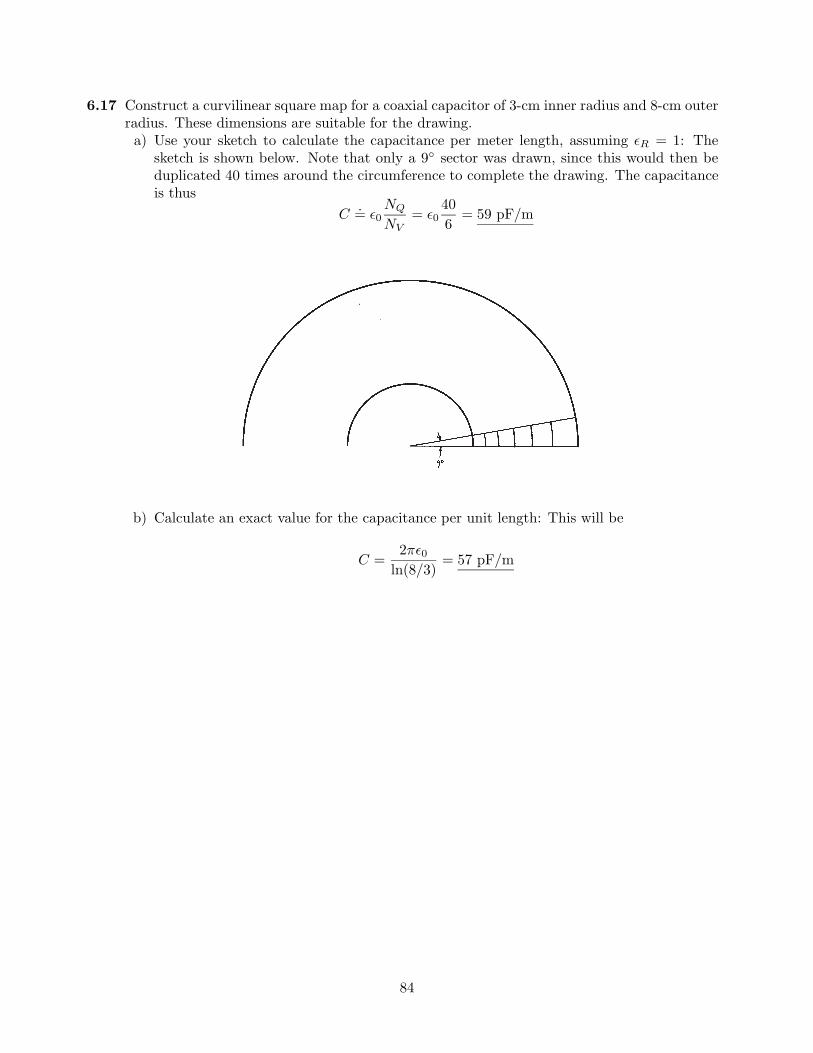
6.17 Construct a curvilinear square map for a coaxial capacitor of 3-cm inner radius and 8-cm outerradius. These dimensions are suitable for the drawing.a) Use your sketch to calculate the capacitance per meter length, assuming ≤R = 1: The
sketch is shown below. Note that only a 9 sector was drawn, since this would then beduplicated 40 times around the circumference to complete the drawing. The capacitanceis thus
C.= ≤0
NQ
NV= ≤0
406
= 59 pF/m
b) Calculate an exact value for the capacitance per unit length: This will be
C =2π≤0
ln(8/3)= 57 pF/m
84
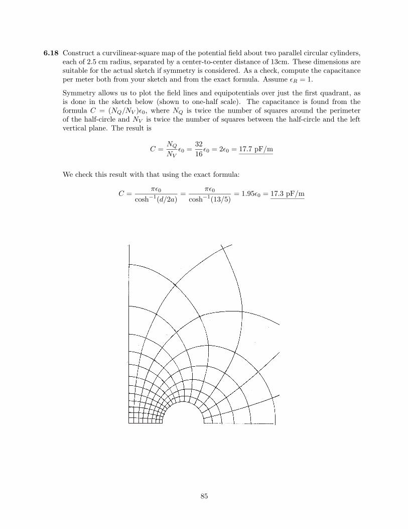
6.18 Construct a curvilinear-square map of the potential field about two parallel circular cylinders,each of 2.5 cm radius, separated by a center-to-center distance of 13cm. These dimensions aresuitable for the actual sketch if symmetry is considered. As a check, compute the capacitanceper meter both from your sketch and from the exact formula. Assume ≤R = 1.
Symmetry allows us to plot the field lines and equipotentials over just the first quadrant, asis done in the sketch below (shown to one-half scale). The capacitance is found from theformula C = (NQ/NV )≤0, where NQ is twice the number of squares around the perimeterof the half-circle and NV is twice the number of squares between the half-circle and the leftvertical plane. The result is
C =NQ
NV≤0 =
3216
≤0 = 2≤0 = 17.7 pF/m
We check this result with that using the exact formula:
C =π≤0
cosh−1(d/2a)=
π≤0cosh−1(13/5)
= 1.95≤0 = 17.3 pF/m
85
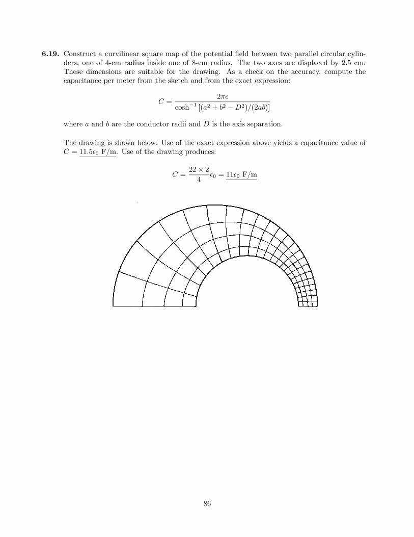
6.19. Construct a curvilinear square map of the potential field between two parallel circular cylin-ders, one of 4-cm radius inside one of 8-cm radius. The two axes are displaced by 2.5 cm.These dimensions are suitable for the drawing. As a check on the accuracy, compute thecapacitance per meter from the sketch and from the exact expression:
C =2π≤
cosh−1 [(a2 + b2 −D2)/(2ab)]
where a and b are the conductor radii and D is the axis separation.
The drawing is shown below. Use of the exact expression above yields a capacitance value ofC = 11.5≤0 F/m. Use of the drawing produces:
C.=
22× 24
≤0 = 11≤0 F/m
86
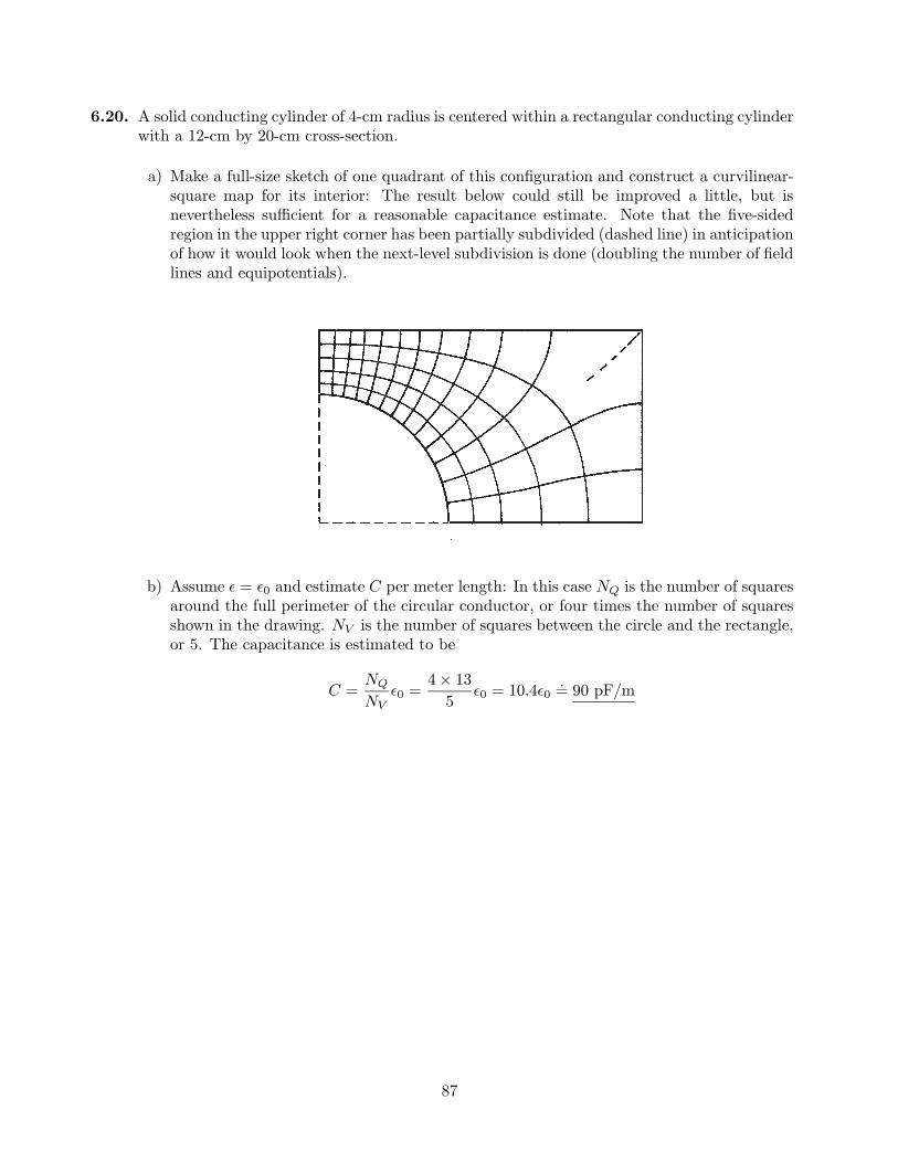
6.20. A solid conducting cylinder of 4-cm radius is centered within a rectangular conducting cylinderwith a 12-cm by 20-cm cross-section.
a) Make a full-size sketch of one quadrant of this configuration and construct a curvilinear-square map for its interior: The result below could still be improved a little, but isnevertheless sufficient for a reasonable capacitance estimate. Note that the five-sidedregion in the upper right corner has been partially subdivided (dashed line) in anticipationof how it would look when the next-level subdivision is done (doubling the number of fieldlines and equipotentials).
b) Assume ≤ = ≤0 and estimate C per meter length: In this case NQ is the number of squaresaround the full perimeter of the circular conductor, or four times the number of squaresshown in the drawing. NV is the number of squares between the circle and the rectangle,or 5. The capacitance is estimated to be
C =NQ
NV≤0 =
4× 135
≤0 = 10.4≤0.= 90 pF/m
87
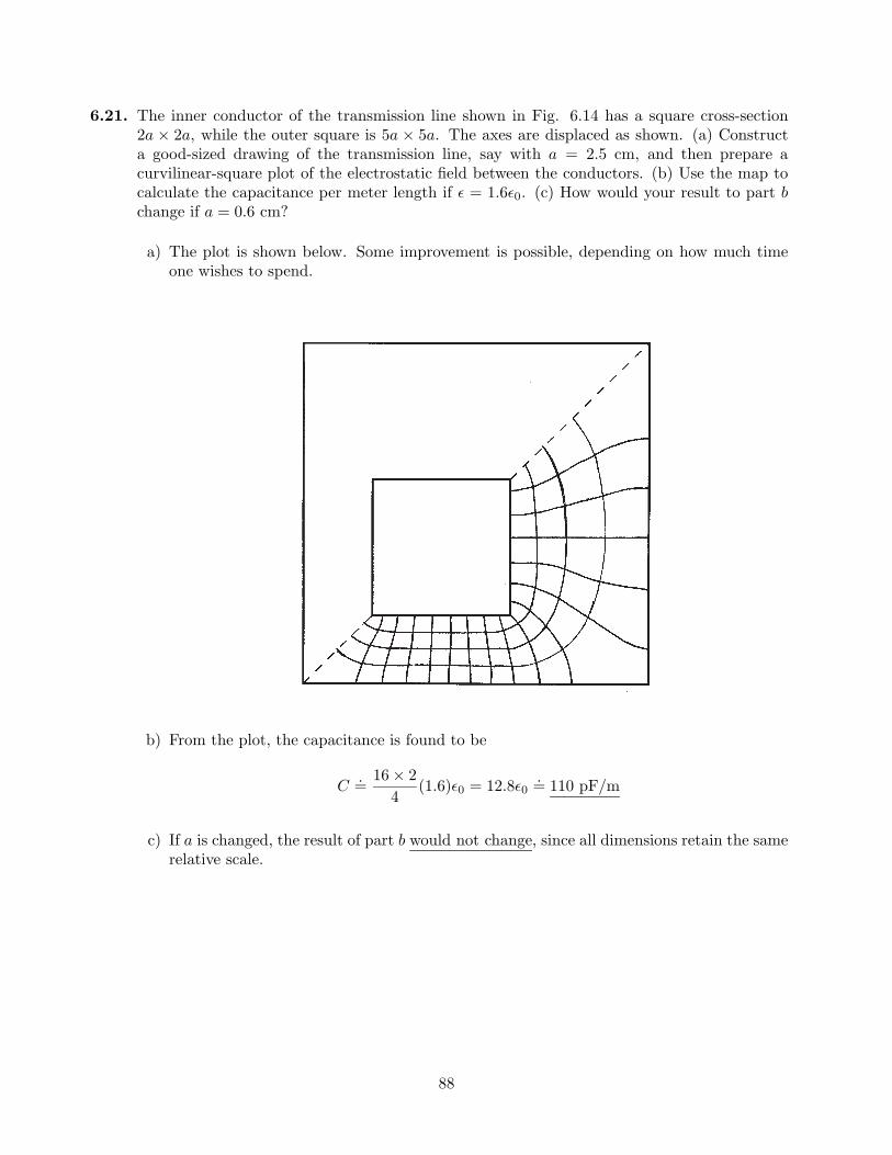
6.21. The inner conductor of the transmission line shown in Fig. 6.14 has a square cross-section2a × 2a, while the outer square is 5a × 5a. The axes are displaced as shown. (a) Constructa good-sized drawing of the transmission line, say with a = 2.5 cm, and then prepare acurvilinear-square plot of the electrostatic field between the conductors. (b) Use the map tocalculate the capacitance per meter length if ≤ = 1.6≤0. (c) How would your result to part bchange if a = 0.6 cm?
a) The plot is shown below. Some improvement is possible, depending on how much timeone wishes to spend.
b) From the plot, the capacitance is found to be
C.=
16× 24
(1.6)≤0 = 12.8≤0.= 110 pF/m
c) If a is changed, the result of part b would not change, since all dimensions retain the samerelative scale.
88
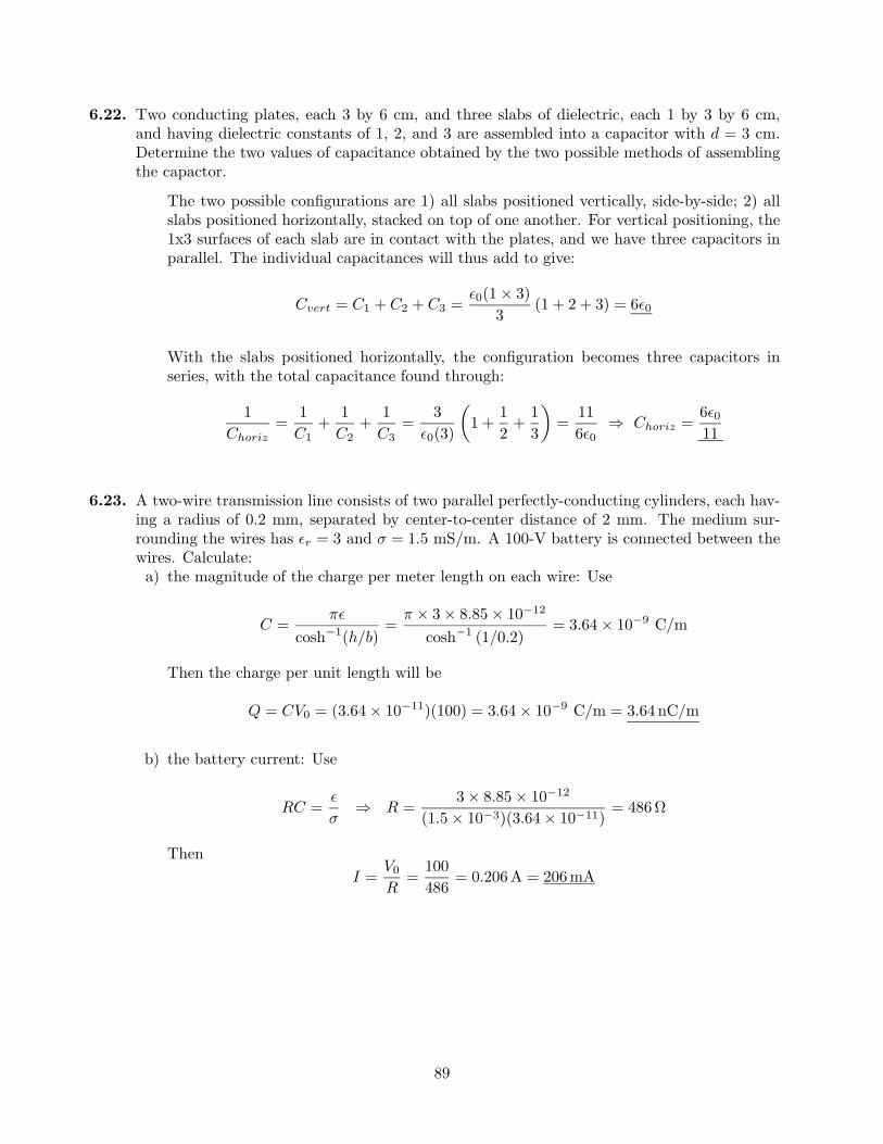
6.22. Two conducting plates, each 3 by 6 cm, and three slabs of dielectric, each 1 by 3 by 6 cm,and having dielectric constants of 1, 2, and 3 are assembled into a capacitor with d = 3 cm.Determine the two values of capacitance obtained by the two possible methods of assemblingthe capactor.
The two possible configurations are 1) all slabs positioned vertically, side-by-side; 2) allslabs positioned horizontally, stacked on top of one another. For vertical positioning, the1x3 surfaces of each slab are in contact with the plates, and we have three capacitors inparallel. The individual capacitances will thus add to give:
Cvert = C1 + C2 + C3 =≤0(1× 3)
3(1 + 2 + 3) = 6≤0
With the slabs positioned horizontally, the configuration becomes three capacitors inseries, with the total capacitance found through:
1Choriz
=1C1
+1C2
+1C3
=3
≤0(3)
µ1 +
12
+13
∂=
116≤0
⇒ Choriz =6≤011
6.23. A two-wire transmission line consists of two parallel perfectly-conducting cylinders, each hav-ing a radius of 0.2 mm, separated by center-to-center distance of 2 mm. The medium sur-rounding the wires has ≤r = 3 and σ = 1.5 mS/m. A 100-V battery is connected between thewires. Calculate:a) the magnitude of the charge per meter length on each wire: Use
C =π≤
cosh−1(h/b)=
π × 3× 8.85× 10−12
cosh−1 (1/0.2)= 3.64× 10⁻⁹ C/m
Then the charge per unit length will be
Q = CV0 = (3.64× 10⁻¹¹)(100) = 3.64× 10⁻⁹ C/m = 3.64 nC/m
b) the battery current: Use
RC =≤
σ⇒ R =
3× 8.85× 10−12
(1.5× 10⁻³)(3.64× 10⁻¹¹)= 486Ω
ThenI =
V0
R=
100486
= 0.206A = 206mA
89
6.24. A potential field in free space is given in spherical coordinates as:
V (r) =Ω
[ρ0/(6≤0)] [3a2 − r2] (r ≤ a)(a3ρ0)/(3≤0r) (r ≥ a)
where ρ0 and a are constants.a) Use Poisson’s equation to find the volume charge density everywhere: Inside r = a, we
apply Poisson’s equation to the potential there:
∇2V1 = −ρv
≤0=
1r2
d
dr
µr2 dV1
dr
∂=
ρ0
6≤01r2
d
dr
°r2(−2r)
¢= −ρ0
≤0
from which we identify ρv = ρ0 (r ≤ a).Outside r = a, we use
∇2V2 = −ρv
≤0=
1r2
d
dr
µr2 dV2
dr
∂=
1r2
d
dr
µr2
µ−a3ρ0
3≤0r2
∂∂= 0
from which ρv = 0 (r ≥ a).
b) find the total charge present: We have a constant charge density confined within a spher-ical volume of radius a. The total charge is therefore Q = (4/3)πa3ρ0 C.
6.25. Let V = 2xy2z3 and ≤ = ≤0. Given point P (1, 2,−1), find:a) V at P : Substituting the coordinates into V , find VP = −8V.b) E at P : We use E = −∇V = −2y2z3ax − 4xyz3ay − 6xy2z2az, which, when evaluated
at P , becomes EP = 8ax + 8ay − 24az V/m
c) ρv at P : This is ρv = ∇ · D = −≤0∇2V = −4xz(z2 + 3y2) C/m3
d) the equation of the equipotential surface passing through P : At P , we know V = −8V,so the equation will be xy2z3 = −4.
e) the equation of the streamline passing through P : First,
Ey
Ex=
dy
dx=
4xyz3
2y2z3=
2xy
Thusydy = 2xdx, and so
12y2 = x2 + C1
Evaluating at P , we find C1 = 1. Next,
Ez
Ex=
dz
dx=
6xy2z2
2y2z3=
3xz
Thus3xdx = zdz, and so
32x2 =
12z2 + C2
Evaluating at P , we find C2 = 1. The streamline is now specified by the equations:y2 − 2x2 = 2 and 3x2 − z2 = 2.
f) Does V satisfy Laplace’s equation? No, since the charge density is not zero.
90
6.26. Given the spherically-symmetric potential field in free space, V = V0e−r/a, find:a) ρv at r = a; Use Poisson’s equation, ∇2V = −ρv/≤, which in this case becomes
−ρv
≤0=
1r2
d
dr
µr2 dV
dr
∂=−V0
ar2
d
dr
≥r2e−r/a
¥=−V0
ar
≥2− r
a
¥e−r/a
from which
ρv(r) =≤0V0
ar
≥2− r
a
¥e−r/a ⇒ ρv(a) =
≤0V0
a2e−1 C/m3
b) the electric field at r = a; this we find through the negative gradient:
E(r) = −∇V = −dV
drar =
V0
ae−r/a ar ⇒ E(a) =
V0
ae−1ar V/m
c) the total charge: The easiest way is to first find the electric flux density, which from partb is D = ≤0E = (≤0V0/a)e−r/a ar. Then the net outward flux of D through a sphere ofradius r would be
Φ(r) = Qencl(r) = 4πr2D = 4π≤0V0r2e−r/a C
As r →∞, this result approaches zero, so the total charge is therefore Qnet = 0.
6.27. Let V (x, y) = 4e2x + f(x)− 3y2 in a region of free space where ρv = 0. It is known that bothEx and V are zero at the origin. Find f(x) and V (x, y): Since ρv = 0, we know that ∇2V = 0,and so
∇2V =∂2V
∂x2+
∂2V
∂y2= 16e2x +
d2f
dx2− 6 = 0
Therefored2f
dx2= −16e2x + 6 ⇒ df
dx= −8e2x + 6x + C1
NowEx =
∂V
∂x= 8e2x +
df
dx
and at the origin, this becomes
Ex(0) = 8 +df
dx
ØØØx=0
= 0(as given)
Thus df/dx |x=0 = −8, and so it follows that C1 = 0. Integrating again, we find
f(x, y) = −4e2x + 3x2 + C2
which at the origin becomes f(0, 0) = −4 + C2. However, V (0, 0) = 0 = 4 + f(0, 0). Sof(0, 0) = −4 and C2 = 0. Finally, f(x, y) = −4e2x + 3x2, and V (x, y) = 4e2x − 4e2x + 3x2 −3y2 = 3(x2 − y2).
91
6.28. Show that in a homogeneous medium of conductivity σ, the potential field V satisfies Laplace’sequation if any volume charge density present does not vary with time: We begin with thecontinuity equation, Eq. (5), Chapter 5:
∇ · J = −∂ρv
∂t
where J = σE, and where, in our homogeneous medium, σ is constant with position. Nowwrite
∇ · J = ∇ · (σE) = σ∇ · (−∇V ) = −σ∇2V = −∂ρv
∂t
This becomes∇2V = 0 (Laplace0s equation)
when ρv is time-independent. Q.E.D.
6.29. Given the potential field V = (Aρ4 + Bρ−4) sin 4φ:a) Show that ∇2V = 0: In cylindrical coordinates,
∇2V =1ρ
∂
∂ρ
µρ∂V
∂ρ
∂+
1ρ2
∂2V
∂φ2
=1ρ
∂
∂ρ
°ρ(4Aρ3 − 4Bρ−5)
¢sin 4φ− 1
ρ216(Aρ4 + Bρ−4) sin 4φ
=16ρ
(Aρ3 + Bρ−5) sin 4φ− 16ρ2
(Aρ4 + Bρ−4) sin 4φ = 0
b) Select A and B so that V = 100 V and |E| = 500 V/m at P (ρ = 1,φ = 22.5, z = 2):First,
E = −∇V = −∂V
∂ρaρ −
1ρ
∂V
∂φaφ
= −4£(Aρ3 −Bρ−5) sin 4φaρ + (Aρ3 + Bρ−5) cos 4φaφ
§
and at P , EP = −4(A − B)aρ. Thus |EP | = ±4(A − B). Also, VP = A + B. Our twoequations are:
4(A−B) = ±500
andA + B = 100
We thus have two pairs of values for A and B:
A = 112.5, B = −12.5 or A = −12.5, B = 112.5
92
6.30. A parallel-plate capacitor has plates located at z = 0 and z = d. The region between platesis filled with a material containing volume charge of uniform density ρ0 C/m3, and which haspermittivity ≤. Both plates are held at ground potential.a) Determine the potential field between plates: We solve Poisson’s equation, under the
assumption that V varies only with z:
∇2V =d2V
dz2= −ρ0
≤⇒ V =
−ρ0z2
2≤+ C1z + C2
At z = 0, V = 0, and so C2 = 0. Then, at z = d, V = 0 as well, so we find C1 = ρ0d/2≤.Finally, V (z) = (ρ0z/2≤)[d− z].
b) Determine the electric field intensity, E between plates: Taking the answer to part a, wefind E through
E = −∇V = −dV
dzaz = − d
dz
hρ0z
2≤(d− z)
i=
ρ0
2≤(2z − d)az V/m
c) Repeat a and b for the case of the plate at z = d raised to potential V0, with the z = 0plate grounded: Begin with
V (z) =−ρ0z2
2≤+ C1z + C2
with C2 = 0 as before, since V (z = 0) = 0. Then
V (z = d) = V0 =−ρ0d2
2≤+ C1d ⇒ C1 =
V0
d+
ρ0d
2≤
So thatV (z) =
V0
dz +
ρ0z
2≤(d− z)
We recognize this as the simple superposition of the voltage as found in part a and thevoltage of a capacitor carrying voltage V0, but without the charged dielectric. The electricfield is now
E = −dV
dzaz =
−V0
daz +
ρ0
2≤(2z − d)az V/m
93
6.31. Let V = (cos 2φ)/ρ in free space.a) Find the volume charge density at point A(0.5, 60, 1): Use Poisson’s equation:
ρv = −≤0∇2V = −≤0
µ1ρ
∂
∂ρ
µρ∂V
∂ρ
∂+
1ρ2
∂2V
∂φ2
∂
= −≤0
µ1ρ
∂
∂ρ
µ− cos 2φ
ρ
∂− 4
ρ2
cos 2φρ
∂=
3≤0 cos 2φρ3
So at A we find:ρvA =
3≤0 cos(120)0.53
= −12≤0 = −106 pC/m3
b) Find the surface charge density on a conductor surface passing through B(2, 30, 1): First,we find E:
E = −∇V = −∂V
∂ρaρ −
1ρ
∂V
∂φaφ
=cos 2φ
ρ2aρ +
2 sin 2φρ2
aφ
At point B the field becomes
EB =cos 60
4aρ +
2 sin 60
4aφ = 0.125aρ + 0.433aφ
The surface charge density will now be
ρsB = ±|DB| = ±≤0|EB| = ±0.451≤0 = ±0.399 pC/m2
The charge is positive or negative depending on which side of the surface we are consid-ering. The problem did not provide information necessary to determine this.
94
6.32. A uniform volume charge has constant density ρv = ρ0 C/m3, and fills the region r < a, inwhich permittivity ≤ as assumed. A conducting spherical shell is located at r = a, and is heldat ground potential. Find:a) the potential everywhere: Inside the sphere, we solve Poisson’s equation, assuming radial
variation only:
∇2V =1r2
d
dr
µr2 dV
dr
∂=−ρ0
≤⇒ V (r) =
−ρ0r2
6≤0+
C1
r+ C2
We require that V is finite at the orgin (or as r → 0), and so therefore C1 = 0. Next,V = 0 at r = a, which gives C2 = ρ0a2/6≤. Outside, r > a, we know the potential mustbe zero, since the sphere is grounded. To show this, solve Laplace’s equation:
∇2V =1r2
d
dr
µr2 dV
dr
∂= 0 ⇒ V (r) =
C1
r+ C2
Requiring V = 0 at both r = a and at infinity leads to C1 = C2 = 0. To summarize
V (r) =Ω ρ0
6≤ (a2 − r2) r < a
0 r > a
b) the electric field intensity, E, everywhere: Use
E = −∇V =−dV
drar =
ρ0r
3≤ar r < a
Outside (r > a), the potential is zero, and so E = 0 there as well.
6.33. The functions V1(ρ,φ, z) and V2(ρ,φ, z) both satisfy Laplace’s equation in the region a < ρ < b,0 ≤ φ < 2π, −L < z < L; each is zero on the surfaces ρ = b for −L < z < L; z = −L fora < ρ < b; and z = L for a < ρ < b; and each is 100 V on the surface ρ = a for −L < z < L.a) In the region specified above, is Laplace’s equation satisfied by the functions V1 + V2,
V1 − V2, V1 + 3, and V1V2? Yes for the first three, since Laplace’s equation is linear. Nofor V1V2.
b) On the boundary surfaces specified, are the potential values given above obtained fromthe functions V1 +V2, V1−V2, V1 +3, and V1V2? At the 100 V surface (ρ = a), No for all.At the 0 V surfaces, yes, except for V1 + 3.
c) Are the functions V1 + V2, V1 − V2, V1 + 3, and V1V2 identical with V1? Only V2 is,since it is given as satisfying all the boundary conditions that V1 does. Therefore, by theuniqueness theorem, V2 = V1. The others, not satisfying the boundary conditions, arenot the same as V1.
95
6.34. Consider the parallel-plate capacitor of Problem 6.30, but this time the charged dielectricexists only between z = 0 and z = b, where b < d. Free space fills the region b < z < d. Bothplates are at ground potential. No surface charge exists at z = b, so that both V and D arecontinuous there. By solving Laplace’s and Poisson’s equations, find:a) V (z) for 0 < z < d: In Region 1 (z < b), we solve Poisson’s equation, assuming z variation
only:d2V1
dz2=−ρ0
≤⇒ dV1
dz=−ρ0z
≤+ C1 (z < b)
In Region 2 (z > b), we solve Laplace’s equation, assuming z variation only:
d2V2
dz2= 0 ⇒ dV2
dz= C0
1 (z > b)
At this stage we apply the first boundary condition, which is continuity of D across theinterface at z = b. Knowing that the electric field magnitude is given by dV/dz, we write
≤dV1
dz
ØØØz=b
= ≤0dV2
dz
ØØØz=b
⇒ −ρ0b + ≤C1 = ≤0C01 ⇒ C0
1 =−ρ0b
≤0+
≤
≤0C1
Substituting the above expression for C01, and performing a second integration on the
Poisson and Laplace equations, we find
V1(z) = −ρ0z2
2≤+ C1z + C2 (z < b)
andV2(z) = −ρ0bz
2≤0+
≤
≤0C1z + C0
2 (z > b)
Next, requiring V1 = 0 at z = 0 leads to C2 = 0. Then, the requirement that V2 = 0 atz = d leads to
0 = −ρ0bd
≤0+
≤
≤0C1d + C0
2 ⇒ C02 =
ρ0bd
≤0− ≤
≤0C1d
With C2 and C02 known, the voltages now become
V1(z) = −ρ0z2
2≤+ C1z and V2(z) =
ρ0b
≤0(d− z)− ≤
≤0C1(d− z)
Finally, to evaluate C1, we equate the two voltage expressions at z = b:
V1|z=b = V2|z=b ⇒ C1 =ρ0b
2≤
∑b + 2≤r(d− b)b + ≤r(d− b)
∏
where ≤r = ≤/≤0. Substituting C1 as found above into V1 and V2 leads to the finalexpressions for the voltages:
V1(z) =ρ0bz
2≤
∑µb + 2≤r(d− b)b + ≤r(d− b)
∂− z
b
∏(z < b)
V2(z) =ρ0b2
2≤0
∑d− z
b + ≤r(d− b)
∏(z > b)
96
6.34b) the electric field intensity for 0 < z < d: This involves taking the negative gradient of the finalvoltage expressions of part a. We find
E1 = −dV1
dzaz =
ρ0
≤
∑z − b
2
µb + 2≤r(d− b)b + ≤r(d− b)
∂∏az V/m (z < b)
E2 = −dV2
dzaz =
ρ0b2
2≤0
∑1
b + ≤r(d− b)
∏az V/m (z > b)
6.35. The conducting planes 2x + 3y = 12 and 2x + 3y = 18 are at potentials of 100 V and 0,respectively. Let ≤ = ≤0 and find:a) V at P (5, 2, 6): The planes are parallel, and so we expect variation in potential in the
direction normal to them. Using the two boundary condtions, our general potentialfunction can be written:
V (x, y) = A(2x + 3y − 12) + 100 = A(2x + 3y − 18) + 0
and so A = −100/6. We then write
V (x, y) = −1006
(2x + 3y − 18) = −1003
x− 50y + 300
and VP = −1003 (5)− 100 + 300 = 33.33 V.
b) Find E at P : Use
E = −∇V =1003
ax + 50ay V/m
6.36. The derivation of Laplace’s and Poisson’s equations assumed constant permittivity, but thereare cases of spatially-varying permittivity in which the equations will still apply. Consider thevector identity, ∇ · (ψG) = G ·∇ψ + ψ∇ ·G, where ψ and G are scalar and vector functions,respectively. Determine a general rule on the allowed directions in which ≤ may vary withrespect to the electric field.
In the original derivation of Poisson’s equation, we started with∇·D = ρv, where D = ≤E.Therefore
∇ · D = ∇ · (≤E) = −∇ · (≤∇V ) = −∇V ·∇≤− ≤∇2V = ρv
We see from this that Poisson’s equation, ∇2V = −ρv/≤, results when ∇V ·∇≤ = 0. Inwords, ≤ is allowed to vary, provided it does so in directions that are normal to the localelectric field.
97
6.37. Coaxial conducting cylinders are located at ρ = 0.5 cm and ρ = 1.2 cm. The region betweenthe cylinders is filled with a homogeneous perfect dielectric. If the inner cylinder is at 100Vand the outer at 0V, find:a) the location of the 20V equipotential surface: From Eq. (35) we have
V (ρ) = 100ln(.012/ρ)
ln(.012/.005)V
We seek ρ at which V = 20 V, and thus we need to solve:
20 = 100ln(.012/ρ)
ln(2.4)⇒ ρ =
.012(2.4)0.2
= 1.01 cm
b) Eρ max: We have
Eρ = −∂V
∂ρ= −dV
dρ=
100ρ ln(2.4)
whose maximum value will occur at the inner cylinder, or at ρ = .5 cm:
Eρ max =100
.005 ln(2.4)= 2.28× 10⁴ V/m = 22.8 kV/m
c) ≤r if the charge per meter length on the inner cylinder is 20 nC/m: The capacitance permeter length is
C =2π≤0≤r
ln(2.4)=
Q
V0
We solve for ≤r:
≤r =(20× 10−9) ln(2.4)
2π≤0(100)= 3.15
6.38. Repeat Problem 6.37, but with the dielectric only partially filling the volume, within 0 < φ <π, and with free space in the remaining volume.
We note that the dielectric changes with φ, and not with ρ. Also, since E is radially-directed and varies only with radius, Laplace’s equation for this case is valid (see Problem6.36) and is the same as that which led to the potential and field in Problem 6.37.Therefore, the solutions to parts a and b are unchanged from Problem 6.37. Part c,however, is different. We write the charge per unit length as the sum of the charges alongeach half of the center conductor (of radius a)
Q = ≤r≤0Eρ,max(πa) + ≤0Eρ,max(πa) = ≤0Eρ,max(πa)(1 + ≤r) C/m
Using the numbers given or found in Problem 6.37, we obtain
1 + ≤r =20× 10−9 C/m
(8.852× 10⁻¹²)(22.8× 10³ V/m)(0.5× 10−2 m)π= 6.31 ⇒ ≤r = 5.31
We may also note that the average dielectric constant in this problem, (≤r + 1)/2, is thesame as that of the uniform dielectric constant found in Problem 6.37.
98
6.39. The two conducting planes illustrated in Fig. 6.14 are defined by 0.001 < ρ < 0.120 m,0 < z < 0.1 m, φ = 0.179 and 0.188 rad. The medium surrounding the planes is air. Forregion 1, 0.179 < φ < 0.188, neglect fringing and find:a) V (φ): The general solution to Laplace’s equation will be V = C1φ + C2, and so
20 = C1(.188) + C2 and 200 = C1(.179) + C2
Subtracting one equation from the other, we find
−180 = C1(.188− .179) ⇒ C1 = −2.00× 10⁴
Then20 = −2.00× 10⁴(.188) + C2 ⇒ C2 = 3.78× 10³
Finally, V (φ) = (−2.00× 10⁴)φ + 3.78× 10³ V.b) E(ρ): Use
E(ρ) = −∇V = −1ρ
dV
dφ=
2.00× 10⁴
ρaφ V/m
c) D(ρ) = ≤0E(ρ) = (2.00× 10⁴≤0/ρ)aφ C/m2.
d) ρs on the upper surface of the lower plane: We use
ρs = D · nØØØsurface
=2.00× 10⁴
ρaφ · aφ =
2.00× 10⁴
ρC/m2
e) Q on the upper surface of the lower plane: This will be
Qt =Z .1
0
Z .120
.001
2.00× 10⁴≤0ρ
dρ dz = 2.00× 10⁴≤0(.1) ln(120) = 8.47× 10⁻⁸ C = 84.7 nC
f) Repeat a) to c) for region 2 by letting the location of the upper plane be φ = .188− 2π,and then find ρs and Q on the lower surface of the lower plane. Back to the beginning,we use
20 = C01(.188− 2π) + C0
2 and 200 = C01(.179) + C0
2
Subtracting one from the other, we find
−180 = C01(.009− 2π) ⇒ C0
1 = 28.7
Then 200 = 28.7(.179) + C02 ⇒ C0
2 = 194.9. Thus V (φ) = 28.7φ + 194.9 in region 2.Then
E = −28.7ρ
aφ V/m and D = −28.7≤0ρ
aφ C/m2
ρs on the lower surface of the lower plane will now be
ρs = −28.7≤0ρ
aφ · (−aφ) =28.7≤0
ρC/m2
The charge on that surface will then be Qb = 28.7≤0(.1) ln(120) = 122 pC.
99
6.39g) Find the total charge on the lower plane and the capacitance between the planes: Total chargewill be Qnet = Qt + Qb = 84.7 nC + 0.122 nC = 84.8 nC. The capacitance will be
C =Qnet
∆V=
84.8200− 20
= 0.471 nF = 471 pF
6.40. A parallel-plate capacitor is made using two circular plates of radius a, with the bottom plateon the xy plane, centered at the origin. The top plate is located at z = d, with its center onthe z axis. Potential V0 is on the top plate; the bottom plate is grounded. Dielectric havingradially-dependent permittivity fills the region between plates. The permittivity is given by≤(ρ) = ≤0(1 + ρ2/a2). Find:a) V (z): Since ≤ varies in the direction normal to E, Laplace’s equation applies, and we
write∇2V =
d2V
dz2= 0 ⇒ V (z) = C1z + C2
With the given boundary conditions, C2 = 0, and C1 = V0/d. Therefore V (z) = V0z/d V.b) E: This will be E = −∇V = −dV/dz az = −(V0/d)az V/m.
c) Q: First we find the electric flux density: D = ≤E = −≤0(1 + ρ2/a2)(V0/d)az C/m2. Thecharge density on the top plate is then ρs = D ·−az = ≤0(1 + ρ2/a2)(V0/d) C/m2. Fromthis we find the charge on the top plate:
Q =Z 2π
0
Z a
0≤0(1 + ρ2/a2)(V0/d) ρ dρ dφ =
3πa2≤0V0
2dC
d) C. The capacitance is C = Q/V0 = 3πa2≤0/(2d) F.
6.41. Concentric conducting spheres are located at r = 5 mm and r = 20 mm. The region betweenthe spheres is filled with a perfect dielectric. If the inner sphere is at 100 V and the outersphere at 0 V:a) Find the location of the 20 V equipotential surface: Solving Laplace’s equation gives us
V (r) = V0
1r −
1b
1a −
1b
where V0 = 100, a = 5 and b = 20. Setting V (r) = 20, and solving for r producesr = 12.5mm.
b) Find Er,max: Use
E = −∇V = −dV
drar =
V0 ar
r2°
1a −
1b
¢
Er,max = E(r = a) =V0
a(1− (a/b))=
1005(1− (5/20))
= 26.7 V/mm = 26.7 kV/m
c) Find ≤r if the surface charge density on the inner sphere is 1.0µC/m2: ρs will be equalin magnitude to the electric flux density at r = a. So ρs = (2.67 × 10⁴ V/m)≤r≤0 =10−6 C/m2. Thus ≤r = 4.23. Note, in the first printing, the given charge density was100µC/m2, leading to a ridiculous answer of ≤r = 423.
100
6.42. The hemisphere 0 < r < a, 0 < θ < π/2, is composed of homogeneous conducting material ofconductivity σ. The flat side of the hemisphere rests on a perfectly-conducting plane. Now,the material within the conical region 0 < θ < α, 0 < r < a, is drilled out, and replaced withmaterial that is perfectly-conducting. An air gap is maintained between the r = 0 tip of thisnew material and the plane. What resistance is measured between the two perfect conductors?Neglect fringing fields.
With no fringing fields, we have θ-variation only in the potential. Laplace’s equation istherefore:
∇2V =1
r2 sin θ
d
dθ
µsin θ
dV
dθ
∂= 0
This reduces todV
dθ=
C1
sin θ⇒ V (θ) = C1 ln tan (θ/2) + C2
We assume zero potential on the plane (at θ = π/2), which means that C2 = 0. On thecone (at θ = α), we assume potential V0, and so V0 = C1 ln tan(α/2)⇒ C1 = V0/ ln tan(α/2) The potential function is now
V (θ) = V0ln tan(θ/2)ln tan(α/2)
α < θ < π/2
The electric field is then
E = −∇V = −1r
dV
dθaθ = − V0
r sin θ ln tan(α/2)aθ V/m
The total current can now be found by integrating the current density, J = σE, over anycross-section. Choosing the lower plane at θ = π/2, this becomes
I =Z 2π
0
Z a
0− σV0
r sin(π/2) ln tan(α/2)aθ · aθ r dr dφ = − 2πaσV0
ln tan(α/2)A
The resistance is finally
R =V0
I= − ln tan(α/2)
2πaσohms
Note that R is in fact positive (despite the minus sign) since ln tan(α/2) is negative whenα < π/2 (which it must be).
101
6.43. Two coaxial conducting cones have their vertices at the origin and the z axis as their axis.Cone A has the point A(1, 0, 2) on its surface, while cone B has the point B(0, 3, 2) on itssurface. Let VA = 100 V and VB = 20 V. Find:
a) α for each cone: Have αA = tan−1(1/2) = 26.57 and αB = tan−1(3/2) = 56.31.
b) V at P (1, 1, 1): The potential function between cones can be written as
V (θ) = C1 ln tan(θ/2) + C2
Then20 = C1 ln tan(56.31/2) + C2 and 100 = C1 ln tan(26.57/2) + C2
Solving these two equations, we find C1 = −97.7 and C2 = −41.1. Now at P , θ =tan−1(
√2) = 54.7. Thus
VP = −97.7 ln tan(54.7/2)− 41.1 = 23.3V
6.44. A potential field in free space is given as V = 100 ln tan(θ/2) + 50 V.a) Find the maximum value of |Eθ| on the surface θ = 40 for 0.1 < r < 0.8 m, 60 < φ <
90. First
E = −1r
dV
dθaθ = − 100
2r tan(θ/2) cos2(θ/2)aθ = − 100
2r sin(θ/2) cos(θ/2)aθ = − 100
r sin θaθ
This will maximize at the smallest value of r, or 0.1:
Emax(θ = 40) = E(r = 0.1, θ = 40) = − 1000.1 sin(40)
aθ = 1.56aθ kV/m
b) Describe the surface V = 80 V: Set 100 ln tan θ/2 + 50 = 80 and solve for θ: Obtainln tan θ/2 = 0.3 ⇒ tan θ/2 = e.3 = 1.35 ⇒ θ = 107 (the cone surface at θ = 107degrees).
102
6.45. In free space, let ρv = 200≤0/r2.4.
a) Use Poisson’s equation to find V (r) if it is assumed that r2Er → 0 when r → 0, and alsothat V → 0 as r →∞: With r variation only, we have
∇2V =1r2
d
dr
µr2 dV
dr
∂= −ρv
≤= −200r−2.4
ord
dr
µr2 dV
dr
∂= −200r−.4
Integrate once: µr2 dV
dr
∂= −200
.6r.6 + C1 = −333.3r.6 + C1
ordV
dr= −333.3r−1.4 +
C1
r2= ∇V (in this case) = −Er
Our first boundary condition states that r2Er → 0 when r → 0 Therefore C1 = 0.Integrate again to find:
V (r) =333.3
.4r−.4 + C2
From our second boundary condition, V → 0 as r →∞, we see that C2 = 0. Finally,
V (r) = 833.3r−.4 V
b) Now find V (r) by using Gauss’ Law and a line integral: Gauss’ law applied to a sphericalsurface of radius r gives:
4πr2Dr = 4πZ r
0
200≤0(r0)2.4
(r0)2dr = 800π≤0r.6
.6
ThusEr =
Dr
≤0=
800π≤0r.6
.6(4π)≤0r2= 333.3r−1.4 V/m
NowV (r) = −
Z r
∞333.3(r0)−1.4dr0 = 833.3r−.4 V
103
6.46. By appropriate solution of Laplace’s and Poisson’s equations, determine the absolute potentialat the center of a sphere of radius a, containing uniform volume charge of density ρ0. Assumepermittivity ≤0 everywhere. HINT: What must be true about the potential and the electricfield at r = 0 and at r = a?
With radial dependence only, Poisson’s equation (applicable to r ≤ a) becomes
∇2V1 =1r2
d
dr
µr2 dV1
dr
∂= −ρ0
≤0⇒ V1(r) = −ρ0r2
6≤0+
C1
r+ C2 (r ≤ a)
For region 2 (r ≥ a) there is no charge and so Laplace’s equation becomes
∇2V2 =1r2
d
dr
µr2 dV2
dr
∂= 0 ⇒ V2(r) =
C3
r+ C4 (r ≥ a)
Now, as r → ∞, V2 → 0, so therefore C4 = 0. Also, as r → 0, V1 must be finite, sotherefore C1 = 0. Then, V must be continuous across the boundary, r = a:
V1
ØØr=a
= V2
ØØr=a
⇒ −ρ0a2
6≤0+ C2 =
C3
a⇒ C2 =
C3
a+
ρ0a2
6≤0
So nowV1(r) =
ρ0
6≤0(a2 − r2) +
C3
aand V2(r) =
C3
r
Finally, since the permittivity is ≤0 everywhere, the electric field will be continuous atr = a. This is equivalent to the continuity of the voltage derivatives:
dV1
dr
ØØØr=a
=dV2
dr
ØØØr=a
⇒ −ρ0a
3≤0= −C3
a2⇒ C3 =
ρ0a3
3≤0
So the potentials in their final forms are
V1(r) =ρ0
6≤0(3a2 − r2) and V2(r) =
ρ0a3
3≤0r
The requested absolute potential at the origin is now V1(r = 0) = ρ0a2/(2≤0) V.
104
CHAPTER 7
7.1a. Find H in cartesian components at P (2, 3, 4) if there is a current filament on the z axis carrying8 mA in the az direction:Applying the Biot-Savart Law, we obtain
Ha =Z ∞
−∞
IdL× aR
4πR2=
Z ∞
−∞
Idz az × [2ax + 3ay + (4− z)az]4π(z2 − 8z + 29)3/2
=Z ∞
−∞
Idz[2ay − 3ax]4π(z2 − 8z + 29)3/2
Using integral tables, this evaluates as
Ha =I
4π
∑2(2z − 8)(2ay − 3ax)52(z2 − 8z + 29)1/2
∏∞
−∞=
I
26π(2ay − 3ax)
Then with I = 8 mA, we finally obtain Ha = −294ax + 196ay µA/m
b. Repeat if the filament is located at x = −1, y = 2: In this case the Biot-Savart integralbecomes
Hb =Z ∞
−∞
Idz az × [(2 + 1)ax + (3− 2)ay + (4− z)az]4π(z2 − 8z + 26)3/2
=Z ∞
−∞
Idz[3ay − ax]4π(z2 − 8z + 26)3/2
Evaluating as before, we obtain with I = 8 mA:
Hb =I
4π
∑2(2z − 8)(3ay − ax)40(z2 − 8z + 26)1/2
∏∞
−∞=
I
20π(3ay − ax) = −127ax + 382ay µA/m
c. Find H if both filaments are present: This will be just the sum of the results of parts a andb, or
HT = Ha + Hb = −421ax + 578ay µA/m
This problem can also be done (somewhat more simply) by using the known result for H froman infinitely-long wire in cylindrical components, and transforming to cartesian components.The Biot-Savart method was used here for the sake of illustration.
7.2. A filamentary conductor is formed into an equilateral triangle with sides of length ` carryingcurrent I. Find the magnetic field intensity at the center of the triangle.
I will work this one from scratch, using the Biot-Savart law. Consider one side of thetriangle, oriented along the z axis, with its end points at z = ±`/2. Then consider apoint, x0, on the x axis, which would correspond to the center of the triangle, and atwhich we want to find H associated with the wire segment. We thus have IdL = Idz az,R =
pz2 + x2
0, and aR = [x0 ax − z az]/R. The differential magnetic field at x0 is now
dH =IdL× aR
4πR2=
Idz az × (x0ax − z az)4π(x2
0 + z2)3/2=
I dz x0 ay
4π(x20 + z2)3/2
where ay would be normal to the plane of the triangle. The magnetic field at x0 is then
H =Z `/2
−`/2
I dz x0 ay
4π(x20 + z2)3/2
=I z ay
4πx0
px2
0 + z2
ØØØ`/2
−`/2=
I`ay
2πx0
p`2 + 4x2
0
105
7.2. (continued). Now, x0 lies at the center of the equilateral triangle, and from the geometry ofthe triangle, we find that x0 = (`/2) tan(30) = `/(2
√3). Substituting this result into the
just-found expression for H leads to H = 3I/(2π`)ay. The contributions from the other twosides of the triangle effectively multiply the above result by three. The final answer is thereforeHnet = 9I/(2π`)ay A/m. It is also possible to work this problem (somewhat more easily) byusing Eq. (9), applied to the triangle geometry.
7.3. Two semi-infinite filaments on the z axis lie in the regions −∞ < z < −a (note typographicalerror in problem statement) and a < z <∞. Each carries a current I in the az direction.a) Calculate H as a function of ρ and φ at z = 0: One way to do this is to use the field from
an infinite line and subtract from it that portion of the field that would arise from thecurrent segment at −a < z < a, found from the Biot-Savart law. Thus,
H =I
2πρaφ −
Z a
−a
I dz az × [ρaρ − z az]4π[ρ2 + z2]3/2
The integral part simplifies and is evaluated:Z a
−a
I dz ρaφ
4π[ρ2 + z2]3/2=
Iρ
4πaφ
z
ρ2p
ρ2 + z2
ØØØa
−a=
Ia
2πρp
ρ2 + a2aφ
Finally,
H =I
2πρ
"
1− apρ2 + a2
#
aφ A/m
b) What value of a will cause the magnitude of H at ρ = 1, z = 0, to be one-half the valueobtained for an infinite filament? We require
"
1− apρ2 + a2
#
ρ=1
=12⇒ a√
1 + a2=
12⇒ a = 1/
√3
7.4. Two circular current loops are centered on the z axis at z = ±h. Each loop has radius a andcarries current I in the aφ direction.a) Find H on the z axis over the range −h < z < h: As a first step, we find the magnetic
field on the z axis arising from a current loop of radius a, centered at the origin in theplane z = 0. It carries a current I in the aφ direction. Using the Biot-Savart law, we haveIdL = Iadφaφ, R =
√a2 + z2, and aR = (zaz − aaρ)/
√a2 + z2. The field on the z axis
is then
H =Z 2π
0
Iadφaφ × (zaz − aaρ)4π(a2 + z2)3/2
=Z 2π
0
Ia2dφaz
4π(a2 + z2)3/2=
a2I
2(a2 + z2)3/2az A/m
In obtaining this result, the term involving aφ × zaz = zaρ has integrated to zero, whentaken over the range 0 < φ < 2π. Substitute aρ = ax cosφ + ay sinφ to show this.We now have two loops, displaced from the x-y plane to z = ±h. The field is now thesuperposition of the two loop fields, which we can construct using displaced versions ofthe H field we just found:
H =a2I
2
"1
[(z − h)2 + a2]3/2+
1[(z + h)2 + a2]3/2
#
az A/m
106
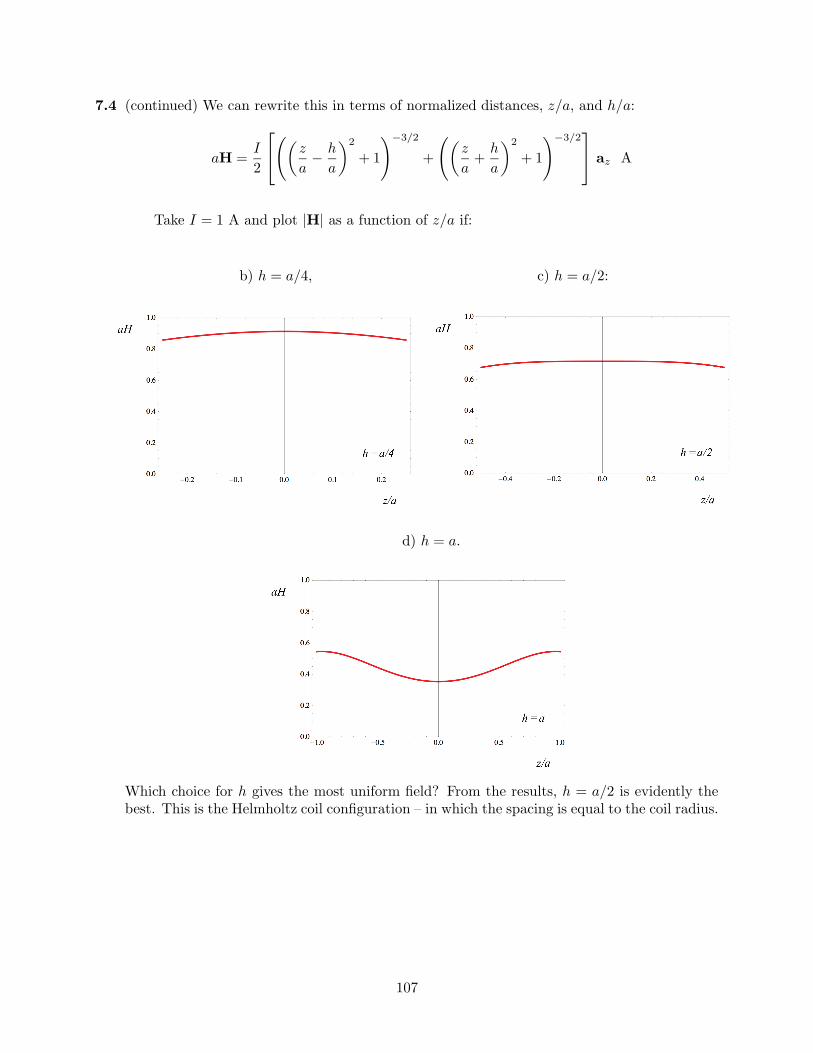
7.4 (continued) We can rewrite this in terms of normalized distances, z/a, and h/a:
aH =I
2
õ
z
a− h
a
∂2
+ 1
!−3/2
+
õz
a+
h
a
∂2
+ 1
!−3/2
az A
Take I = 1 A and plot |H| as a function of z/a if:
b) h = a/4, c) h = a/2:
d) h = a.
Which choice for h gives the most uniform field? From the results, h = a/2 is evidently thebest. This is the Helmholtz coil configuration – in which the spacing is equal to the coil radius.
107
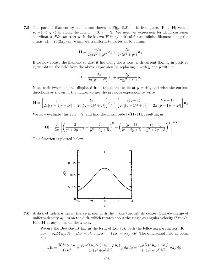
7.5. The parallel filamentary conductors shown in Fig. 8.21 lie in free space. Plot |H| versusy, −4 < y < 4, along the line x = 0, z = 2: We need an expression for H in cartesiancoordinates. We can start with the known H in cylindrical for an infinite filament along thez axis: H = I/(2πρ)aφ, which we transform to cartesian to obtain:
H =−Iy
2π(x2 + y2)ax +
Ix
2π(x2 + y2)ay
If we now rotate the filament so that it lies along the x axis, with current flowing in positivex, we obtain the field from the above expression by replacing x with y and y with z:
H =−Iz
2π(y2 + z2)ay +
Iy
2π(y2 + z2)az
Now, with two filaments, displaced from the x axis to lie at y = ±1, and with the currentdirections as shown in the figure, we use the previous expression to write
H =∑
Iz
2π[(y + 1)2 + z2]− Iz
2π[(y − 1)2 + z2]
∏ay +
∑I(y − 1)
2π[(y − 1)2 + z2]− I(y + 1)
2π[(y + 1)2 + z2]
∏az
We now evaluate this at z = 2, and find the magnitude (√
H · H), resulting in
|H| =I
2π
"µ2
y2 + 2y + 5− 2
y2 − 2y + 5
∂2
+µ
(y − 1)y2 − 2y + 5
− (y + 1)y2 + 2y + 5
∂2#1/2
This function is plotted below
7.6. A disk of radius a lies in the xy plane, with the z axis through its center. Surface charge ofuniform density ρs lies on the disk, which rotates about the z axis at angular velocity Ω rad/s.Find H at any point on the z axis.
We use the Biot-Savart law in the form of Eq. (6), with the following parameters: K =ρsv = ρsρΩaφ, R =
pz2 + ρ2, and aR = (z az − ρaρ)/R. The differential field at point
z is
dH =Kda× aR
4πR2=
ρsρΩaφ × (z az − ρaρ)4π(z2 + ρ2)3/2
ρ dρ dφ =ρsρΩ (z aρ + ρaz)
4π(z2 + ρ2)3/2ρ dρ dφ
108
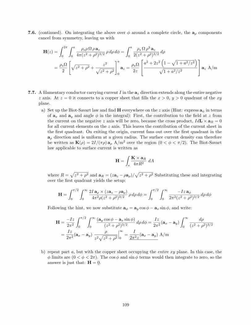
7.6. (continued). On integrating the above over φ around a complete circle, the aρ componentscancel from symmetry, leaving us with
H(z) =Z 2π
0
Z a
0
ρsρΩ ρaz
4π(z2 + ρ2)3/2ρ dρ dφ =
Z a
0
ρs Ω ρ3 az
2(z2 + ρ2)3/2dρ
=ρsΩ2
"p
z2 + ρ2 +z2
pz2 + ρ2
#a
0
az =ρsΩ2z
a2 + 2z2
≥1−
p1 + a2/z2
¥
p1 + a2/z2
az A/m
7.7. A filamentary conductor carrying current I in the az direction extends along the entire negativez axis. At z = 0 it connects to a copper sheet that fills the x > 0, y > 0 quadrant of the xyplane.a) Set up the Biot-Savart law and find H everywhere on the z axis (Hint: express aφ in terms
of ax and ay and angle φ in the integral): First, the contribution to the field at z fromthe current on the negative z axis will be zero, because the cross product, IdL× aR = 0for all current elements on the z axis. This leaves the contribution of the current sheet inthe first quadrant. On exiting the origin, current fans out over the first quadrant in theaρ direction and is uniform at a given radius. The surface current density can thereforebe written as K(ρ) = 2I/(πρ)aρ A/m2 over the region (0 < φ < π/2). The Biot-Savartlaw applicable to surface current is written as
H =Z
s
K× aR
4πR2dA
where R =p
z2 + ρ2 and aR = (zaz − ρaρ)/p
z2 + ρ2 Substituting these and integratingover the first quadrant yields the setup:
H =Z π/2
0
Z ∞
0
2I aρ × (zaz − ρaρ)4π2ρ(z2 + ρ2)3/2
ρ dρ dφ =Z π/2
0
Z ∞
0
−Iz aφ
2π2(z2 + ρ2)3/2dρ dφ
Following the hint, we now substitute aφ = ay cosφ− ax sinφ, and write:
H =−Iz
2π2
Z π/2
0
Z ∞
0
(ay cosφ− ax sinφ)(z2 + ρ2)3/2
dρ dφ =Iz
2π2(ax − ay)
Z ∞
0
dρ
(z2 + ρ2)3/2
=Iz
2π2(ax − ay)
ρ
z2p
z2 + ρ2
ØØØ∞
0=
I
2π2z(ax − ay) A/m
b) repeat part a, but with the copper sheet occupying the entire xy plane. In this case, theφ limits are (0 < φ < 2π). The cosφ and sinφ terms would then integrate to zero, so theanswer is just that: H = 0.
109
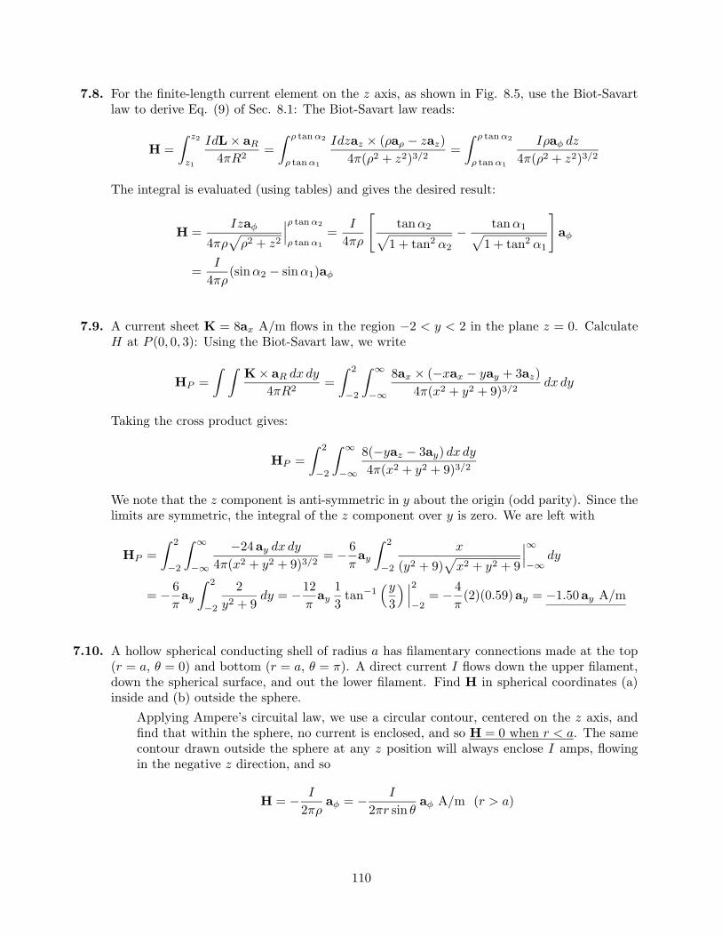
7.8. For the finite-length current element on the z axis, as shown in Fig. 8.5, use the Biot-Savartlaw to derive Eq. (9) of Sec. 8.1: The Biot-Savart law reads:
H =Z z2
z1
IdL× aR
4πR2=
Z ρ tan α2
ρ tan α1
Idzaz × (ρaρ − zaz)4π(ρ2 + z2)3/2
=Z ρ tan α2
ρ tan α1
Iρaφ dz
4π(ρ2 + z2)3/2
The integral is evaluated (using tables) and gives the desired result:
H =Izaφ
4πρp
ρ2 + z2
ØØØρ tan α2
ρ tan α1=
I
4πρ
"tanα2p
1 + tan2 α2
− tanα1p1 + tan2 α1
#
aφ
=I
4πρ(sinα2 − sinα1)aφ
7.9. A current sheet K = 8ax A/m flows in the region −2 < y < 2 in the plane z = 0. CalculateH at P (0, 0, 3): Using the Biot-Savart law, we write
HP =Z Z
K× aR dx dy
4πR2=
Z 2
−2
Z ∞
−∞
8ax × (−xax − yay + 3az)4π(x2 + y2 + 9)3/2
dx dy
Taking the cross product gives:
HP =Z 2
−2
Z ∞
−∞
8(−yaz − 3ay) dx dy
4π(x2 + y2 + 9)3/2
We note that the z component is anti-symmetric in y about the origin (odd parity). Since thelimits are symmetric, the integral of the z component over y is zero. We are left with
HP =Z 2
−2
Z ∞
−∞
−24ay dx dy
4π(x2 + y2 + 9)3/2= − 6
πay
Z 2
−2
x
(y2 + 9)p
x2 + y2 + 9
ØØØ∞
−∞dy
= − 6πay
Z 2
−2
2y2 + 9
dy = −12π
ay13
tan−1≥y
3
¥ ØØØ2
−2= − 4
π(2)(0.59)ay = −1.50ay A/m
7.10. A hollow spherical conducting shell of radius a has filamentary connections made at the top(r = a, θ = 0) and bottom (r = a, θ = π). A direct current I flows down the upper filament,down the spherical surface, and out the lower filament. Find H in spherical coordinates (a)inside and (b) outside the sphere.
Applying Ampere’s circuital law, we use a circular contour, centered on the z axis, andfind that within the sphere, no current is enclosed, and so H = 0 when r < a. The samecontour drawn outside the sphere at any z position will always enclose I amps, flowingin the negative z direction, and so
H = − I
2πρaφ = − I
2πr sin θaφ A/m (r > a)
110
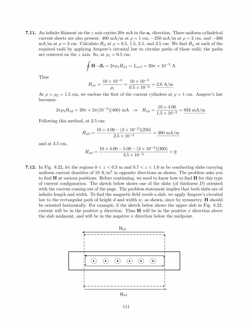
7.11. An infinite filament on the z axis carries 20π mA in the az direction. Three uniform cylindricalcurrent sheets are also present: 400 mA/m at ρ = 1 cm, −250 mA/m at ρ = 2 cm, and −300mA/m at ρ = 3 cm. Calculate Hφ at ρ = 0.5, 1.5, 2.5, and 3.5 cm: We find Hφ at each of therequired radii by applying Ampere’s circuital law to circular paths of those radii; the pathsare centered on the z axis. So, at ρ1 = 0.5 cm:
IH · dL = 2πρ1Hφ1 = Iencl = 20π × 10−3 A
ThusHφ1 =
10× 10−3
ρ1=
10× 10−3
0.5× 10−2= 2.0 A/m
At ρ = ρ2 = 1.5 cm, we enclose the first of the current cylinders at ρ = 1 cm. Ampere’s lawbecomes:
2πρ2Hφ2 = 20π + 2π(10−2)(400) mA ⇒ Hφ2 =10 + 4.001.5× 10−2
= 933 mA/m
Following this method, at 2.5 cm:
Hφ3 =10 + 4.00− (2× 10⁻²)(250)
2.5× 10−2= 360 mA/m
and at 3.5 cm,
Hφ4 =10 + 4.00− 5.00− (3× 10⁻²)(300)
3.5× 10−2= 0
7.12. In Fig. 8.22, let the regions 0 < z < 0.3 m and 0.7 < z < 1.0 m be conducting slabs carryinguniform current densities of 10 A/m2 in opposite directions as shown. The problem asks youto find H at various positions. Before continuing, we need to know how to find H for this typeof current configuration. The sketch below shows one of the slabs (of thickness D) orientedwith the current coming out of the page. The problem statement implies that both slabs are ofinfinite length and width. To find the magnetic field inside a slab, we apply Ampere’s circuitallaw to the rectangular path of height d and width w, as shown, since by symmetry, H shouldbe oriented horizontally. For example, if the sketch below shows the upper slab in Fig. 8.22,current will be in the positive y direction. Thus H will be in the positive x direction abovethe slab midpoint, and will be in the negative x direction below the midpoint.
Hout
Hout
111
7.12. (continued). In taking the line integral in Ampere’s law, the two vertical path segments willcancel each other. Ampere’s circuital law for the interior loop becomes
IH · dL = 2Hin × w = Iencl = J × w × d ⇒ Hin =
Jd
2
The field outside the slab is found similarly, but with the enclosed current now bounded bythe slab thickness, rather than the integration path height:
2Hout × w = J × w ×D ⇒ Hout =JD
2
where Hout is directed from right to left below the slab and from left to right above the slab(right hand rule). Reverse the current, and the fields, of course, reverse direction. We are nowin a position to solve the problem. Find H at:a) z = −0.2m: Here the fields from the top and bottom slabs (carrying opposite currents)
will cancel, and so H = 0.
b) z = 0.2m. This point lies within the lower slab above its midpoint. Thus the field willbe oriented in the negative x direction. Referring to Fig. 8.22 and to the sketch on theprevious page, we find that d = 0.1. The total field will be this field plus the contributionfrom the upper slab current:
H =−10(0.1)
2ax
| z lower slab
− 10(0.3)2
ax
| z upper slab
= −2ax A/m
c) z = 0.4m: Here the fields from both slabs will add constructively in the negative xdirection:
H = −210(0.3)
2ax = −3ax A/m
d) z = 0.75m: This is in the interior of the upper slab, whose midpoint lies at z = 0.85.Therefore d = 0.2. Since 0.75 lies below the midpoint, magnetic field from the upperslab will lie in the negative x direction. The field from the lower slab will be negativex-directed as well, leading to:
H =−10(0.2)
2ax
| z upper slab
− 10(0.3)2
ax
| z lower slab
= −2.5ax A/m
e) z = 1.2m: This point lies above both slabs, where again fields cancel completely: ThusH = 0.
112
7.13. A hollow cylindrical shell of radius a is centered on the z axis and carries a uniform surfacecurrent density of Kaaφ.
a) Show that H is not a function of φ or z: Consider this situation as illustrated in Fig.8.11. There (sec. 8.2) it was stated that the field will be entirely z-directed. We can seethis by applying Ampere’s circuital law to a closed loop path whose orientation we choosesuch that current is enclosed by the path. The only way to enclose current is to set upthe loop (which we choose to be rectangular) such that it is oriented with two parallelopposing segments lying in the z direction; one of these lies inside the cylinder, the otheroutside. The other two parallel segments lie in the ρ direction. The loop is now cut by thecurrent sheet, and if we assume a length of the loop in z of d, then the enclosed currentwill be given by Kd A. There will be no φ variation in the field because where we positionthe loop around the circumference of the cylinder does not affect the result of Ampere’slaw. If we assume an infinite cylinder length, there will be no z dependence in the field,since as we lengthen the loop in the z direction, the path length (over which the integralis taken) increases, but then so does the enclosed current – by the same factor. Thus Hwould not change with z. There would also be no change if the loop was simply movedalong the z direction.
b) Show that Hφ and Hρ are everywhere zero. First, if Hφ were to exist, then we should beable to find a closed loop path that encloses current, in which all or or portion of the pathlies in the φ direction. This we cannot do, and so Hφ must be zero. Another argument isthat when applying the Biot-Savart law, there is no current element that would producea φ component. Again, using the Biot-Savart law, we note that radial field componentswill be produced by individual current elements, but such components will cancel fromtwo elements that lie at symmetric distances in z on either side of the observation point.
c) Show that Hz = 0 for ρ > a: Suppose the rectangular loop was drawn such that theoutside z-directed segment is moved further and further away from the cylinder. Wewould expect Hz outside to decrease (as the Biot-Savart law would imply) but the sameamount of current is always enclosed no matter how far away the outer segment is. Wetherefore must conclude that the field outside is zero.
d) Show that Hz = Ka for ρ < a: With our rectangular path set up as in part a, we have nopath integral contributions from the two radial segments, and no contribution from theoutside z-directed segment. Therefore, Ampere’s circuital law would state that
IH · dL = Hzd = Iencl = Kad ⇒ Hz = Ka
where d is the length of the loop in the z direction.
e) A second shell, ρ = b, carries a current Kbaφ. Find H everywhere: For ρ < a we wouldhave both cylinders contributing, or Hz(ρ < a) = Ka +Kb. Between the cylinders, we areoutside the inner one, so its field will not contribute. Thus Hz(a < ρ < b) = Kb. Outside(ρ > b) the field will be zero.
113
7.14. A toroid having a cross section of rectangular shape is defined by the following surfaces: thecylinders ρ = 2 and ρ = 3 cm, and the planes z = 1 and z = 2.5 cm. The toroid carries asurface current density of −50az A/m on the surface ρ = 3 cm. Find H at the point P (ρ,φ, z):The construction is similar to that of the toroid of round cross section as done on p.239. Again,magnetic field exists only inside the toroid cross section, and is given by
H =Iencl
2πρaφ (2 < ρ < 3) cm, (1 < z < 2.5) cm
where Iencl is found from the given current density: On the outer radius, the current is
Iouter = −50(2π × 3× 10−2) = −3π A
This current is directed along negative z, which means that the current on the inner radius(ρ = 2) is directed along positive z. Inner and outer currents have the same magnitude. It isthe inner current that is enclosed by the circular integration path in aφ within the toroid thatis used in Ampere’s law. So Iencl = +3π A. We can now proceed with what is requested:
a) PA(1.5cm, 0, 2cm): The radius, ρ = 1.5 cm, lies outside the cross section, and so HA = 0.
b) PB(2.1cm, 0, 2cm): This point does lie inside the cross section, and the φ and z values donot matter. We find
HB =Iencl
2πρaφ =
3aφ
2(2.1× 10⁻²)= 71.4aφ A/m
c) PC(2.7cm,π/2, 2cm): again, φ and z values make no difference, so
HC =3aφ
2(2.7× 10⁻²)= 55.6aφ A/m
d) PD(3.5cm,π/2, 2cm). This point lies outside the cross section, and so HD = 0.
7.15. Assume that there is a region with cylindrical symmetry in which the conductivity is given byσ = 1.5e−150ρ kS/m. An electric field of 30az V/m is present.a) Find J: Use
J = σE = 45e−150ρ az kA/m2
b) Find the total current crossing the surface ρ < ρ0, z = 0, all φ:
I =Z Z
J · dS =Z 2π
0
Z ρ0
045e−150ρρ dρ dφ =
2π(45)(150)2
e−150ρ [−150ρ− 1]ØØØρ0
0kA
= 12.6£1− (1 + 150ρ0)e−150ρ0
§A
c) Make use of Ampere’s circuital law to find H: Symmetry suggests that H will be φ-directed only, and so we consider a circular path of integration, centered on and perpen-dicular to the z axis. Ampere’s law becomes: 2πρHφ = Iencl, where Iencl is the currentfound in part b, except with ρ0 replaced by the variable, ρ. We obtain
Hφ =2.00ρ
£1− (1 + 150ρ)e−150ρ
§A/m
114
7.16. A current filament carrying I in the −az direction lies along the entire positive z axis. At theorigin, it connects to a conducting sheet that forms the xy plane.a) Find K in the conducting sheet: The current fans outward radially with uniform surface
current density at a fixed radius. The current density at radius ρ will be the total current,I, divided by the circumference at radius ρ:
K =I
2πρaρ A/m
b) Use Ampere’s circuital law to find H everywhere for z > 0: Circular lines of H areexpected, centered on the z axis – in the −aφ direction. Ampere’s law is set up byconsidering a circular path integral taken around the wire at fixed z. The enclosed currentis that which passes through any surface that is bounded by the line integration path:
IH · dL = 2πρHφ = Iencl
If the surface is that of the disk whose perimeter is the integration path, then the enclosedcurrent is just I, and the magnetic field becomes
Hφ = − I
2πρ⇒ H = − I
2πρaφ A/m
But the disk surface can be “stretched” so that it forms a balloon shape. Suppose the“balloon” is a right circular cylinder, with its open top circumference at the path integrallocation. The cylinder extends downward, intersecting the surface current in the x-yplane, with the bottom of the cylinder below the x-y plane. Now, the path integral isunchanged from before, and the enclosed current is the radial current in the x-y planethat passes through the side of the cylinder. This current will be I = 2πρ[I/(2πρ)] = I,as before. So the answer given above for H applies to anywhere in the region z > 0.
c) Find H for z < 0: Consider the same cylinder as in part b, except take the path inte-gral of H around the bottom circumference (below the x-y plane). The enclosed currentnow consists of the filament current that enters through the top, plus the radial currentthat exits though the side. The two currents are equal magnitude but opposite in sign.Therefore, the net enclosed current is zero, and thus H = 0 (z < 0).
115
7.17. A current filament on the z axis carries a current of 7 mA in the az direction, and currentsheets of 0.5az A/m and −0.2az A/m are located at ρ = 1 cm and ρ = 0.5 cm, respectively.Calculate H at:a) ρ = 0.5 cm: Here, we are either just inside or just outside the first current sheet, so
both we will calculate H for both cases. Just inside, applying Ampere’s circuital law toa circular path centered on the z axis produces:
2πρHφ = 7× 10⁻³ ⇒ H(just inside) =7× 10⁻³
2π(0.5× 10⁻²aφ = 2.2× 10⁻¹aφ A/m
Just outside the current sheet at .5 cm, Ampere’s law becomes
2πρHφ = 7× 10⁻³ − 2π(0.5× 10⁻²)(0.2)
⇒ H(just outside) =7.2× 10⁻⁴
2π(0.5× 10⁻²)aφ = 2.3× 10⁻²aφ A/m
b) ρ = 1.5 cm: Here, all three currents are enclosed, so Ampere’s law becomes
2π(1.5× 10⁻²)Hφ = 7× 10⁻³ − 6.28× 10⁻³ + 2π(10−2)(0.5)
⇒ H(ρ = 1.5) = 3.4× 10⁻¹aφ A/m
c) ρ = 4 cm: Ampere’s law as used in part b applies here, except we replace ρ = 1.5 cm withρ = 4 cm on the left hand side. The result is H(ρ = 4) = 1.3× 10⁻¹aφ A/m.
d) What current sheet should be located at ρ = 4 cm so that H = 0 for all ρ > 4 cm? Werequire that the total enclosed current be zero, and so the net current in the proposedcylinder at 4 cm must be negative the right hand side of the first equation in part b. Thiswill be −3.2× 10⁻², so that the surface current density at 4 cm must be
K =−3.2× 10⁻²
2π(4× 10⁻²)az = −1.3× 10⁻¹ az A/m
7.18. A wire of 3-mm radius is made up of an inner material (0 < ρ < 2 mm) for which σ = 107
S/m, and an outer material (2mm < ρ < 3mm) for which σ = 4× 10⁷ S/m. If the wire carriesa total current of 100 mA dc, determine H everywhere as a function of ρ.
Since the materials have different conductivities, the current densities within them willdiffer. Electric field, however is constant throughout. The current can be expressed as
I = π(.002)2J1 + π[(.003)2 − (.002)2]J2 = π£(.002)2σ1 + [(.003)2 − (.002)2]σ2
§E
Solve for E to obtain
E =0.1
π[(4× 10⁻⁶)(107) + (9× 10⁻⁶ − 4× 10⁻⁶)(4× 10⁷)]= 1.33× 10⁻⁴ V/m
We next apply Ampere’s circuital law to a circular path of radius ρ, where ρ < 2mm:
2πρHφ1 = πρ2J1 = πρ2σ1E ⇒ Hφ1 =σ1Eρ
2= 663 A/m
116
7.18 (continued) . Next, for the region 2mm < ρ < 3mm, Ampere’s law becomes
2πρHφ2 = π[(4× 10⁻⁶)(107) + (ρ2 − 4× 10⁻⁶)(4× 10⁷)]E
⇒ Hφ2 = 2.7× 10³ρ − 8.0× 10⁻³
ρA/m
Finally, for ρ > 3mm, the field outside is that for a long wire:
Hφ3 =I
2πρ=
0.12πρ
=1.6× 10⁻²
ρA/m
7.19. In spherical coordinates, the surface of a solid conducting cone is described by θ = π/4 and aconducting plane by θ = π/2. Each carries a total current I. The current flows as a surfacecurrent radially inward on the plane to the vertex of the cone, and then flows radially-outwardthroughout the cross-section of the conical conductor.a) Express the surface current density as a function of r: This will be the total current
divided by the circumference of a circle of radius r in the plane, directed toward theorigin:
K(r) = − I
2πrar A/m2 (θ = π/2)
b) Express the volume current density inside the cone as a function of r: This will be thetotal current divided by the area of the spherical cap subtending angle θ = π/4:
J(r) = I
"Z 2π
0
Z π/4
0r2 sin θ0 dθ0 dφ
#−1
ar =I ar
2πr2(1− 1/√
2)A/m2 (0 < θ < π/4)
c) Determine H as a function of r and θ in the region between the cone and the plane: Fromsymmetry, we expect H to be φ-directed and uniform at constant r and θ. Ampere’scircuital law can therefore be stated as:
IH · dL = 2πr sin θ Hφ = I ⇒ H =
I
2πr sin θaφ A/m (π/4 < θ < π/2)
d) Determine H as a function of r and θ inside the cone: Again, φ-directed H is anticipated,so we apply Ampere’s law in the following way:
IH · dL = 2πr sin θ Hφ =
Z
sJ · dS =
Z 2π
0
Z θ
0
I ar
2πr2(1− 1/√
2)· ar r2 sin θ0 dθ0 dφ
This becomes2πr sin θ Hφ = −2π
I
2π(1− 1/√
2)cos θ0
ØØØθ
0
orH =
I
2πr(1− 1/√
2)
∑(1− cos θ)
sin θ
∏aφ A/m (0 < θ < π/4)
As a test of this, note that the inside and outside fields (results of parts c and d) are equalat the cone surface (θ = π/4) as they must be.
117
7.20. A solid conductor of circular cross-section with a radius of 5 mm has a conductivity that varieswith radius. The conductor is 20 m long and there is a potential difference of 0.1 V dc betweenits two ends. Within the conductor, H = 105ρ2aφ A/m.a) Find σ as a function of ρ: Start by finding J from H by taking the curl. With H
φ-directed, and varying with radius only, the curl becomes:
J = ∇×H =1ρ
d
dρ(ρHφ) az =
1ρ
d
dρ
°105ρ3
¢az = 3× 10⁵ρaz A/m2
Then E = 0.1/20 = 0.005az V/m, which we then use with J = σE to find
σ =J
E=
3× 10⁵ρ
0.005= 6× 10⁷ρ S/m
b) What is the resistance between the two ends? The current in the wire is
I =Z
sJ · dS = 2π
Z a
0(3× 10⁵ρ) ρ dρ = 6π × 105
µ13a3
∂= 2π × 105(0.005)3 = 0.079 A
Finally, R = V0/I = 0.1/0.079 = 1.3 Ω
118
7.21. A cylindrical wire of radius a is oriented with the z axis down its center line. The wire carriesa non-uniform current down its length of density J = bρaz A/m2, where b is a constant.a) What total current flows in the wire? We integrate the current density over the wire
cross-section:
Itot =Z
sJ · dS =
Z 2π
0
Z a
0bρaz · az ρ dρ dφ =
2πba3
3A
b) find Hin (0 < ρ < a), as a function of ρ: From the symmetry, φ-directed H (= Hφ aφ)is expected in the interior; this will be constant at a fixed radius, ρ. Apply Ampere’scircuital law to a circular path of radius ρ inside:
IHin · dL = 2πρHφ,in =
Z
sJ · dS =
Z 2π
0
Z ρ
0bρ0 az · az ρ0 dρ0 dφ =
2πbρ3
3
So thatHin =
bρ2
3aφ A/m (0 < ρ < a)
c) find Hout(ρ > a), as a function of ρ Same as part b, except the path integral is taken ata radius outside the wire:
IHout · dL = 2πρHφ,out =
Z
sJ · dS =
Z 2π
0
Z a
0bρaz · az ρ dρ dφ =
2πba3
3
So thatHout =
ba3
3ρaφ A/m (ρ > a)
d) verify your results of parts b and c by using ∇×H = J: With a φ component of H only,varying only with ρ, the curl in cylindrical coordinates reduces to
J = ∇×H =1ρ
d
dρ(ρHφ)az
Apply this to the inside field to get
Jin =1ρ
d
dρ
µbρ3
3
∂az = bρaz
For the outside field, we find
Jout =1ρ
d
dρ
µρba3
3ρ
∂az = 0
as expected.
119
7.22. A solid cylinder of radius a and length L, where L >> a, contains volume charge of uniformdensity ρ0 C/m3. The cylinder rotates about its axis (the z axis) at angular velocity Ω rad/s.a) Determine the current density J, as a function of position within the rotating cylinder:
Use J = ρ0v = ρ0ρΩaφ A/m2.
b) Determine the magnetic field intensity H inside and outside: It helps initially to obtainthe field on-axis. To do this, we use the result of Problem 8.6, but give the rotatingcharged disk in that problem a differential thickness, dz. We can then evaluate the on-axis field in the rotating cylinder as the superposition of fields from a stack of disks whichexist between ±L/2. Here, we make the problem easier by letting L→∞ (since L >> a)thereby specializing our evaluation to positions near the half-length. The on-axis field istherefore:
Hz(ρ = 0) =Z ∞
−∞
ρ0Ω2z
a2 + 2z2
≥1−
p1 + a2/z2
¥
p1 + a2/z2
dz
= 2Z ∞
0
ρ0Ω2
∑a2
√z2 + a2
+2z2
√z2 + a2
− 2z∏
dz
= 2ρ0Ω∑a2
2ln(z +
pz2 + a2) +
z
2
pz2 + a2 − a2
2ln(z +
pz2 + a2)− z2
2
∏∞
0
= ρ0Ωhzp
z2 + a2 − z2i∞0
= ρ0Ωhzp
z2 + a2 − z2i
z→∞
Using the large z approximation in the radical, we obtain
Hz(ρ = 0) = ρ0Ω∑z2
µ1 +
a2
2z2
∂− z2
∏=
ρ0Ωa2
2
To find the field as a function of radius, we apply Ampere’s circuital law to a rectangularloop, drawn in two locations described as follows: First, construct the rectangle with oneside along the z axis, and with the opposite side lying at any radius outside the cylinder.In taking the line integral of H around the rectangle, we note that the two segments thatare perpendicular to the cylinder axis will have their path integrals exactly cancel, sincethe two path segments are oppositely-directed, while from symmetry the field should notbe different along each segment. This leaves only the path segment that coindides withthe axis, and that lying parallel to the axis, but outside. Choosing the length of thesesegments to be `, Ampere’s circuital law becomes:
IH · dL = Hz(ρ = 0)` + Hz(ρ > a)` = Iencl =
Z
sJ · dS =
Z `
0
Z a
0ρ0ρΩaφ · aφ dρ dz
= `ρ0Ωa2
2But we found earlier that Hz(ρ = 0) = ρ0Ωa2/2. Therefore, we identify the outside field,Hz(ρ > a) = 0. Next, change the rectangular path only by displacing the central pathcomponent off-axis by distance ρ, but still lying within the cylinder. The enclosed currentis now somewhat less, and Ampere’s law becomes
IH · dL = Hz(ρ)` + Hz(ρ > a)` = Iencl =
Z
sJ · dS =
Z `
0
Z a
ρρ0ρ
0Ωaφ · aφ dρ dz
= `ρ0Ω2
(a2 − ρ2) ⇒ H(ρ) =ρ0Ω2
(a2 − ρ2)az A/m
120
7.22c) Check your result of part b by taking the curl of H. With H z-directed, and varying only withρ, the curl in cylindrical coordinates becomes
∇×H = −dHz
dρaφ = ρ0Ωρaφ A/m2 = J
as expected.
7.23. Given the field H = 20ρ2 aφ A/m:a) Determine the current density J: This is found through the curl of H, which simplifies
to a single term, since H varies only with ρ and has only a φ component:
J = ∇×H =1ρ
d(ρHφ)dρ
az =1ρ
d
dρ
°20ρ3
¢az = 60ρaz A/m2
b) Integrate J over the circular surface ρ = 1, 0 < φ < 2π, z = 0, to determine the totalcurrent passing through that surface in the az direction: The integral is:
I =Z Z
J · dS =Z 2π
0
Z 1
060ρaz · ρ dρ dφaz = 40π A
c) Find the total current once more, this time by a line integral around the circular pathρ = 1, 0 < φ < 2π, z = 0:
I =I
H · dL =Z 2π
020ρ2 aφ
ØØρ=1
· (1)dφaφ =Z 2π
020 dφ = 40π A
121
7.24. Infinitely-long filamentary conductors are located in the y = 0 plane at x = n meters wheren = 0,±1,±2, . . . Each carries 1 A in the az direction.a) Find H on the y axis. As a help,
∞X
n=1
y
y2 + n2=
π
2− 1
2y+
π
e2πy − 1
We can begin by determining the field on the y axis arising from two wires only, locatedat x = ±n. We start from basics, using the Biot-Savart law:
H =Z
IdL× aR
4πR2
where R =°n2 + y2 + z2
¢2 for both wires, and where, for the wire at x = +n
a+R =
−nax + yay + zaz
(n2 + y2 + z2)1/2and a−R =
nax + yay + zaz
(n2 + y2 + z2)1/2
for the wire located at x = −n. Then with IdL = dz az (I = 1) for both wires, theBiot-Savart construction becomes
H =Z ∞
−∞
dz az × [(−nax + yay + zaz) + (nax + yay + zaz)]4π (n2 + y2 + z2)3/2
=−yax
2π
Z ∞
−∞
dz
(n2 + y2 + z2)3/2
This evaluates asH = − 1
π
µy
n2 + y2
∂ax A/m
Now if we include all wire pairs, the result is the superposition of an infinite number offields of the above form. Specifically,
Hnet = − 1π
∞X
n=1
µy
n2 + y2
∂ax A/m
Using the given closed form of the series expansion, our final answer is
Hnet = −∑12− 1
2πy+
1e2πy − 1
∏ax A/m
b) Compare your result of part a to that obtained if the filaments are replaced by a currentsheet in the y = 0 plane that carries surface current density K = 1az A/m: This is foundthrough Eq. (11):
H =12K× aN =
12az × ay = −1
2ax
Our answer of part a approaches this value as y → ∞, demonstrating that at largedistances, the parallel wires act like a current sheet. Interestingly, at close-in locations,such that 2πy << 1, we may expand e2πy .= 1 + 2πy, leading to the cancellation of thelast two terms in the part a result, and again, Hnet
.= −1/2ax.
122
7.25. When x, y, and z are positive and less than 5, a certain magnetic field intensity may beexpressed as H = [x2yz/(y +1)]ax +3x2z2ay− [xyz2/(y +1)]az. Find the total current in theax direction that crosses the strip, x = 2, 1 ≤ y ≤ 4, 3 ≤ z ≤ 4, by a method utilizing:a) a surface integral: We need to find the current density by taking the curl of the given H.
Actually, since the strip lies parallel to the yz plane, we need only find the x componentof the current density, as only this component will contribute to the requested current.This is
Jx = (∇×H)x =µ
∂Hz
∂y− ∂Hy
∂z
∂= −
µxz2
(y + 1)2+ 6x2z
∂ax
The current through the strip is then
I =Z
sJ · ax da = −
Z 4
3
Z 4
1
µ2z2
(y + 1)2+ 24z
∂dy dz = −
Z 4
3
µ−2z2
(y + 1)+ 24zy
∂4
1
dz
= −Z 4
3
µ35z2 + 72z
∂dz = −
µ15z3 + 36z2
∂4
3
= −259
b) a closed line integral: We integrate counter-clockwise around the strip boundary (usingthe right-hand convention), where the path normal is positive ax. The current is then
I =I
H · dL =Z 4
13(2)2(3)2 dy +
Z 4
3− 2(4)z2
(4 + 1)dz +
Z 1
43(2)2(4)2 dy +
Z 3
4− 2(1)z2
(1 + 1)dz
= 108(3)− 815
(43 − 33) + 192(1− 4)− 13(33 − 43) = −259
7.26. Consider a sphere of radius r = 4 centered at (0,0,3). Let S1 be that portion of the sphericalsurface that lies above the xy plane. Find
RS1
(∇ × H) · dS if H = 3ρaφ in cylindricalcoordinates: First, the intersection of the sphere with the x-y plane is a disk in the plane ofradius ρd =
√42 − 32 =
√7. The curl of the given field (having a φ component that varies
only with ρ) is
∇×H =1ρ
d
dρ(ρHφ)az =
1ρ
d
dρ
°3ρ2
¢az = 6az
Since this is a constant field, its flux through S1 will simply be the flux through the disk,which in turn is simply the product of the field with the disk area:
Φ = 6× π(√
7)2 = 42π
Another way to solve the problem is to use Stokes’ theorem and write the flux as
Φ =I
H · dL
where the path integral is taken around the disk perimeter. Doing this gives:
Φ = 2πρdHφ|ρd = 2π√
7× 3√
7 = 42π
123
7.27. The magnetic field intensity is given in a certain region of space as
H =x + 2y
z2ay +
2z
az A/m
a) Find∇×H: For this field, the general curl expression in rectangular coordinates simplifiesto
∇×H = −∂Hy
∂zax +
∂Hy
∂xaz =
2(x + 2y)z3
ax +1z2
az A/m
b) Find J: This will be the answer of part a, since ∇×H = J.
c) Use J to find the total current passing through the surface z = 4, 1 < x < 2, 3 < y < 5,in the az direction: This will be
I =Z Z
JØØz=4
· az dx dy =Z 5
3
Z 2
1
142
dx dy = 1/8 A
d) Show that the same result is obtained using the other side of Stokes’ theorem: We takeHH · dL over the square path at z = 4 as defined in part c. This involves two integrals of
the y component of H over the range 3 < y < 5. Integrals over x, to complete the loop,do not exist since there is no x component of H. We have
I =I
HØØz=4
· dL =Z 5
3
2 + 2y16
dy +Z 3
5
1 + 2y16
dy =18(2)− 1
16(2) = 1/8 A
124
7.28. Given H = (3r2/ sin θ)aθ + 54r cos θaφ A/m in free space:a) find the total current in the aθ direction through the conical surface θ = 20, 0 ≤ φ ≤ 2π,
0 ≤ r ≤ 5, by whatever side of Stokes’ theorem you like best. I chose the line integralside, where the integration path is the circular path in φ around the top edge of the cone,at r = 5. The path direction is chosen to be clockwise looking down on the xy plane.This, by convention, leads to the normal from the cone surface that points in the positiveaθ direction (right hand rule). We find
IH · dL =
Z 2π
0
£(3r2/ sin θ)aθ + 54r cos θaφ
§r=5,θ=20
· 5 sin(20) dφ (−aφ)
= −2π(54)(25) cos(20) sin(20) = −2.73× 10³ A
This result means that there is a component of current that enters the cone surface inthe −aθ direction, to which is associated a component of H in the positive aφ direction.
b) Check the result by using the other side of Stokes’ theorem: We first find the currentdensity through the curl of the magnetic field, where three of the six terms in the sphericalcoordinate formula survive:
∇×H =1
r sin θ
∂
∂θ(54r cos θ sin θ)) ar −
1r
∂
∂r
°54r2 cos θ
¢aθ +
1r
∂
∂r
µ3r3
sin θ
∂aφ = J
ThusJ = 54 cot θ ar − 108 cos θ aθ +
9rsin θ
aφ
The calculation of the other side of Stokes’ theorem now involves integrating J over thesurface of the cone, where the outward normal is positive aθ, as defined in part a:
Z
S(∇×H) · dS =
Z 2π
0
Z 5
0
∑54 cot θ ar − 108 cos θ aθ +
9rsin θ
aφ
∏
20· aθ r sin(20) dr dφ
= −Z 2π
0
Z 5
0108 cos(20) sin(20)rdrdφ = −2π(54)(25) cos(20) sin(20)
= −2.73× 10³ A
125
7.29. A long straight non-magnetic conductor of 0.2 mm radius carries a uniformly-distributedcurrent of 2 A dc.a) Find J within the conductor: Assuming the current is +z directed,
J =2
π(0.2× 10⁻³)2az = 1.59× 10⁷ az A/m2
b) Use Ampere’s circuital law to find H and B within the conductor: Inside, at radius ρ, wehave
2πρHφ = πρ2J ⇒ H =ρJ
2aφ = 7.96× 10⁶ρaφ A/m
Then B = µ0H = (4π × 10−7)(7.96× 10⁶)ρaφ = 10ρaφ Wb/m2.
c) Show that ∇×H = J within the conductor: Using the result of part b, we find,
∇×H =1ρ
d
dρ(ρHφ)az =
1ρ
d
dρ
µ1.59× 10⁷ρ2
2
∂az = 1.59× 10⁷ az A/m2 = J
d) Find H and B outside the conductor (note typo in book): Outside, the entire current isenclosed by a closed path at radius ρ, and so
H =I
2πρaφ =
1πρ
aφ A/m
Now B = µ0H = µ0/(πρ)aφ Wb/m2.
e) Show that ∇×H = J outside the conductor: Here we use H outside the conductor andwrite:
∇×H =1ρ
d
dρ(ρHφ)az =
1ρ
d
dρ
µρ
1πρ
∂az = 0 (as expected)
7.30. (an inversion of Problem 8.20). A solid nonmagnetic conductor of circular cross-section hasa radius of 2mm. The conductor is inhomogeneous, with σ = 106(1 + 106ρ2) S/m. If theconductor is 1m in length and has a voltage of 1mV between its ends, find:a) H inside: With current along the cylinder length (along az, and with φ symmetry, H
will be φ-directed only. We find E = (V0/d)az = 10−3az V/m. Then J = σE =103(1+106ρ2)az A/m2. Next we apply Ampere’s circuital law to a circular path of radiusρ, centered on the z axis and normal to the axis:
IH · dL = 2πρHφ =
Z Z
SJ · dS =
Z 2π
0
Z ρ
0103(1 + 106(ρ0)2)az · azρ
0dρ0dφ
ThusHφ =
103
ρ
Z ρ
0ρ0 + 106(ρ0)3dρ0 =
103
ρ
∑ρ2
2+
106
4ρ4
∏
Finally, H = 500ρ(1 + 5× 10⁵ρ3)aφ A/m (0 < ρ < 2mm).
b) the total magnetic flux inside the conductor: With field in the φ direction, a plane normalto B will be that in the region 0 < ρ < 2 mm, 0 < z < 1 m. The flux will be
Φ =Z Z
SB·dS = µ0
Z 1
0
Z 2×10⁻³
0
°500ρ + 2.5× 10⁸ρ3
¢dρdz = 8π×10−10 Wb = 2.5 nWb
126
7.31. The cylindrical shell defined by 1 cm < ρ < 1.4 cm consists of a non-magnetic conductingmaterial and carries a total current of 50 A in the az direction. Find the total magnetic fluxcrossing the plane φ = 0, 0 < z < 1:
a) 0 < ρ < 1.2 cm: We first need to find J, H, and B: The current density will be:
J =50
π[(1.4× 10⁻²)2 − (1.0× 10⁻²)2]az = 1.66× 10⁵ az A/m2
Next we find Hφ at radius ρ between 1.0 and 1.4 cm, by applying Ampere’s circuital law,and noting that the current density is zero at radii less than 1 cm:
2πρHφ = Iencl =Z 2π
0
Z ρ
10−21.66× 10⁵ρ0 dρ0 dφ
⇒ Hφ = 8.30× 10⁴ (ρ2 − 10−4)ρ
A/m (10−2 m < ρ < 1.4× 10⁻² m)
Then B = µ0H, or
B = 0.104(ρ2 − 10−4)
ρaφ Wb/m2
Now,
Φa =Z Z
B · dS =Z 1
0
Z 1.2×10⁻²
10−20.104
∑ρ− 10−4
ρ
∏dρ dz
= 0.104∑(1.2× 10⁻²)2 − 10−4
2− 10−4 ln
µ1.21.0
∂∏= 3.92× 10⁻⁷ Wb = 0.392µWb
b) 1.0 cm < ρ < 1.4 cm (note typo in book): This is part a over again, except we change theupper limit of the radial integration:
Φb =Z Z
B · dS =Z 1
0
Z 1.4×10⁻²
10−20.104
∑ρ− 10−4
ρ
∏dρ dz
= 0.104∑(1.4× 10⁻²)2 − 10−4
2− 10−4 ln
µ1.41.0
∂∏= 1.49× 10⁻⁶ Wb = 1.49µWb
c) 1.4 cm < ρ < 20 cm: This is entirely outside the current distribution, so we need B there:We modify the Ampere’s circuital law result of part a to find:
Bout = 0.104[(1.4× 10⁻²)2 − 10−4]
ρaφ =
10−5
ρaφ Wb/m2
We now find
Φc =Z 1
0
Z 20×10−2
1.4×10⁻²
10−5
ρdρ dz = 10−5 ln
µ201.4
∂= 2.7× 10⁻⁵ Wb = 27µWb
127
7.32. The free space region defined by 1 < z < 4 cm and 2 < ρ < 3 cm is a toroid of rectangularcross-section. Let the surface at ρ = 3 cm carry a surface current K = 2az kA/m.a) Specify the current densities on the surfaces at ρ = 2 cm, z = 1cm, and z = 4cm.
All surfaces must carry equal currents. With this requirement, we find: K(ρ = 2) =−3az kA/m. Next, the current densities on the z = 1 and z = 4 surfaces must transistionbetween the current density values at ρ = 2 and ρ = 3. Knowing the the radial currentdensity will vary as 1/ρ, we find K(z = 1) = (60/ρ)aρ A/m with ρ in meters. Similarly,K(z = 4) = −(60/ρ)aρ A/m.
b) Find H everywhere: Outside the toroid, H = 0. Inside, we apply Ampere’s circuital lawin the manner of Problem 8.14:
IH · dL = 2πρHφ =
Z 2π
0K(ρ = 2) · az (2× 10⁻²) dφ
⇒ H = −2π(3000)(.02)ρ
aφ = −60/ρaφ A/m (inside)
c) Calculate the total flux within the toriod: We have B = −(60µ0/ρ)aφ Wb/m2. Then
Φ =Z .04
.01
Z .03
.02
−60µ0
ρaφ · (−aφ) dρ dz = (.03)(60)µ0 ln
µ32
∂= 0.92µWb
7.33. Use an expansion in rectangular coordinates to show that the curl of the gradient of any scalarfield G is identically equal to zero. We begin with
∇G =∂G
∂xax +
∂G
∂yay +
∂G
∂zaz
and∇×∇G =
∑∂
∂y
µ∂G
∂z
∂− ∂
∂z
µ∂G
∂y
∂∏ax +
∑∂
∂z
µ∂G
∂x
∂− ∂
∂x
µ∂G
∂z
∂∏ay
+∑
∂
∂x
µ∂G
∂y
∂− ∂
∂y
µ∂G
∂x
∂∏az = 0 for any G
128
7.34. A filamentary conductor on the z axis carries a current of 16A in the az direction, a conductingshell at ρ = 6 carries a total current of 12A in the −az direction, and another shell at ρ = 10carries a total current of 4A in the −az direction.a) Find H for 0 < ρ < 12: Ampere’s circuital law states that
HH · dL = Iencl, where the
line integral and current direction are related in the usual way through the right handrule. Therefore, if I is in the positive z direction, H is in the aφ direction. We proceedas follows:
0 < ρ < 6 : 2πρHφ = 16 ⇒ H = 16/(2πρ)aφ
6 < ρ < 10 : 2πρHφ = 16− 12 ⇒ H = 4/(2πρ)aφ
ρ > 10 : 2πρHφ = 16− 12− 4 = 0 ⇒ H = 0
b) Plot Hφ vs. ρ:
c) Find the total flux Φ crossing the surface 1 < ρ < 7, 0 < z < 1: This will be
Φ =Z 1
0
Z 6
1
16µ0
2πρdρ dz +
Z 1
0
Z 7
6
4µ0
2πρdρ dz =
2µ0
π[4 ln 6 + ln(7/6)] = 5.9 µWb
129
7.35. A current sheet, K = 20az A/m, is located at ρ = 2, and a second sheet, K = −10az A/m islocated at ρ = 4.a.) Let Vm = 0 at P (ρ = 3,φ = 0, z = 5) and place a barrier at φ = π. Find Vm(ρ,φ, z) for−π < φ < π: Since the current is cylindrically-symmetric, we know that H = I/(2πρ) aφ,where I is the current enclosed, equal in this case to 2π(2)K = 80π A. Thus, using theresult of Section 8.6, we find
Vm = − I
2πφ = −80π
2πφ = −40φ A
which is valid over the region 2 < ρ < 4, −π < φ < π, and −∞ < z <∞. For ρ > 4, theouter current contributes, leading to a total enclosed current of
Inet = 2π(2)(20)− 2π(4)(10) = 0
With zero enclosed current, Hφ = 0, and the magnetic potential is zero as well.b) Let A = 0 at P and find A(ρ,φ, z) for 2 < ρ < 4: Again, we know that H = Hφ(ρ),
since the current is cylindrically symmetric. With the current only in the z direction, andagain using symmmetry, we expect only a z component of A which varies only with ρ.We can then write:
∇×A = −dAz
dρaφ = B =
µ0I
2πρaφ
ThusdAz
dρ= −µ0I
2πρ⇒ Az = −µ0I
2πln(ρ) + C
We require that Az = 0 at ρ = 3. Therefore C = [(µ0I)/(2π)] ln(3), Then, with I = 80π,we finally obtain
A = −µ0(80π)2π
[ln(ρ)− ln(3)]az = 40µ0 lnµ
3ρ
∂az Wb/m
7.36. Let A = (3y − z)ax + 2xzay Wb/m in a certain region of free space.a) Show that ∇ · A = 0:
∇ · A =∂
∂x(3y − z) +
∂
∂y2xz = 0
b) At P (2,−1, 3), find A, B, H, and J: First AP = −6ax + 12ay. Then, using the curlformula in cartesian coordinates,
B = ∇×A = −2xax − ay + (2z − 3)az ⇒ BP = −4ax − ay + 3az Wb/m2
NowHP = (1/µ0)BP = −3.2× 10⁶ax − 8.0× 10⁵ay + 2.4× 10⁶az A/m
Then J = ∇×H = (1/µ0)∇×B = 0, as the curl formula in cartesian coordinates shows.
130
7.37. Let N = 1000, I = 0.8 A, ρ0 = 2 cm, and a = 0.8 cm for the toroid shown in Fig. 8.12b. FindVm in the interior of the toroid if Vm = 0 at ρ = 2.5 cm, φ = 0.3π. Keep φ within the range0 < φ < 2π: Well-within the toroid, we have
H =NI
2πρaφ = −∇Vm = −1
ρ
dVm
dφaφ
ThusVm = −NIφ
2π+ C
Then,
0 = −1000(0.8)(0.3π)2π
+ C
or C = 120. Finally
Vm =∑120− 400
πφ
∏A (0 < φ < 2π)
131
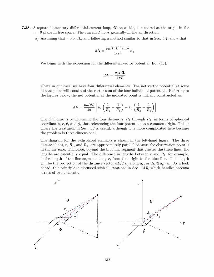
7.38. A square filamentary differential current loop, dL on a side, is centered at the origin in thez = 0 plane in free space. The current I flows generally in the aφ direction.a) Assuming that r >> dL, and following a method similar to that in Sec. 4.7, show that
dA =µ0I(dL)2 sin θ
4πr2aφ
We begin with the expression for the differential vector potential, Eq. (48):
dA =µ0IdL4πR
where in our case, we have four differential elements. The net vector potential at somedistant point will consist of the vector sum of the four individual potentials. Referring tothe figures below, the net potential at the indicated point is initially constructed as:
dA =µ0IdL
4π
∑ax
µ1
R2− 1
R1
∂+ ay
µ1
R3− 1
R4
∂∏
The challenge is to determine the four distances, R1 through R4, in terms of sphericalcoordinates, r, θ, and φ, thus referencing the four potentials to a common origin. This iswhere the treatment in Sec. 4.7 is useful, although it is more complicated here becausethe problem is three-dimensional.
The diagram for the y-displaced elements is shown in the left-hand figure. The threedistance lines, r, R1, and R2, are approximately parallel because the observation point isin the far zone. Therefore, beyond the blue line segment that crosses the three lines, thelengths are essentially equal. The difference in lengths between r and R1, for example,is the length of the line segment along r, from the origin to the blue line. This lengthwill be the projection of the distance vector dL/2ay along ar, or dL/2ay · ar. As a lookahead, this principle is discussed with illustrations in Sec. 14.5, which handles antennaarrays of two elements.
132
7.38a) (continued). We now may write:
R1.= r −
∑dL
2ay · ar
∏and R2
.= r +∑dL
2ay · ar
∏
Referring to the right-hand figure and applying similar reasoning there leads to
R3.= r −
∑dL
2ax · ar
∏and R4
.= r +∑dL
2ax · ar
∏
where we know that ax · ar = sin θ cosφ and ay · ar = sin θ sinφ We now substitute allthese relations into the original expression for dA:
dA =µ0IdL
4π
"õr +
dL
2sin θ sinφ
∂−1
−µ
r − dL
2sin θ sinφ
∂−1!
ax
+
√µr − dL
2sin θ cosφ
∂−1
−µ
r +dL
2sin θ cosφ
∂−1!
ay
#
=µ0IdL
4πr
"õ1 +
dL
2rsin θ sinφ
∂−1
−µ
1− dL
2rsin θ sinφ
∂−1!
ax
+
√µ1− dL
2rsin θ cosφ
∂−1
−µ
1 +dL
2rsin θ cosφ
∂−1!
ay
#
Now, since dL/r << 1, this simplifies to
dA .=µ0IdL
4πr
∑µµ1− dL
2rsin θ sinφ
∂−
µ1 +
dL
2rsin θ sinφ
∂∂ax
+µµ
1 +dL
2rsin θ cosφ
∂−
µ1− dL
2rsin θ cosφ
∂∂ay
∏
=µ0I(dL)2 sin θ
4πr2[− sinφax + cosφay]
=µ0I(dL)2 sin θ
4πr2aφ
b) Show that
dH =I(dL)2
4πr3(2 cos θ ar + sin θ aθ)
Using the part a expression, we construct dH = (1/µ0)∇×dA, where in this case, we havea φ-directed dA that varies with r and θ. The curl expression in spherical coordinatesreduces to:
∇× dA =1
r sin θ
∂(dA sin θ)∂θ
ar −1r
∂(rdA)∂r
aθ
or
∇× dA =1
r sin θ
∂
∂θ
µI(dL)2 sin2 θ
4πr2
∂ar −
1r
∂
∂r
µI(dL)2 sin θ
4πr
∂aθ
=I(dL)2
4πr3(2 cos θ ar + sin θ aθ)
133
7.39. Planar current sheets of K = 30az A/m and −30az A/m are located in free space at x = 0.2and x = −0.2 respectively. For the region −0.2 < x < 0.2:a) Find H: Since we have parallel current sheets carrying equal and opposite currents, we
use Eq. (12), H = K×aN , where aN is the unit normal directed into the region betweencurrents, and where either one of the two currents are used. Choosing the sheet at x = 0.2,we find
H = 30az ×−ax = −30ay A/m
b) Obtain and expression for Vm if Vm = 0 at P (0.1, 0.2, 0.3): Use
H = −30ay = −∇Vm = −dVm
dyay
SodVm
dy= 30 ⇒ Vm = 30y + C1
Then0 = 30(0.2) + C1 ⇒ C1 = −6 ⇒ Vm = 30y − 6 A
c) Find B: B = µ0H = −30µ0ay Wb/m2.
d) Obtain an expression for A if A = 0 at P : We expect A to be z-directed (with thecurrent), and so from ∇×A = B, where B is y-directed, we set up
−dAz
dx= −30µ0 ⇒ Az = 30µ0x + C2
Then 0 = 30µ0(0.1) + C2 ⇒ C2 = −3µ0. So finally A = µ0(30x− 3)az Wb/m.
7.40. Show that the line integral of the vector potential A about any closed path is equal to themagnetic flux enclosed by the path, or
HA · dL =
RB · dS.
We use the fact that B = ∇×A, and substitute this into the desired relation to findI
A · dL =Z∇×A · dS
This is just a statement of Stokes’ theorem (already proved), so we are done.
134
7.41. Assume that A = 50ρ2az Wb/m in a certain region of free space.a) Find H and B: Use
B = ∇×A = −∂Az
∂ρaφ = −100ρaφ Wb/m2
Then H = B/µ0 = −100ρ/µ0 aφ A/m.
b) Find J: Use
J = ∇×H =1ρ
∂
∂ρ(ρHφ)az =
1ρ
∂
∂ρ
µ−100ρ2
µ0
∂az = −200
µ0az A/m2
c) Use J to find the total current crossing the surface 0 ≤ ρ ≤ 1, 0 ≤ φ < 2π, z = 0: Thecurrent is
I =Z Z
J · dS =Z 2π
0
Z 1
0
−200µ0
az · az ρ dρ dφ =−200π
µ0A = −500 MA
d) Use the value of Hφ at ρ = 1 to calculateH
H · dL for ρ = 1, z = 0: Have
IH · dL = I =
Z 2π
0
−100µ0
aφ · aφ (1)dφ =−200π
µ0A = −500 MA
7.42. Show that ∇2(1/R12) = −∇1(1/R12) = R21/R312. First
∇2
µ1
R12
∂= ∇2
£(x2 − x1)2 + (y2 − y1)2 + (z2 − z1)2
§−1/2
= −12
∑2(x2 − x1)ax + 2(y2 − y1)ay + 2(z2 − z1)az
[(x2 − x1)2 + (y2 − y1)2 + (z2 − z1)2]3/2
∏=−R12
R312
=R21
R312
Also note that ∇1(1/R12) would give the same result, but of opposite sign.
135
7.43. Compute the vector magnetic potential within the outer conductor for the coaxial line whosevector magnetic potential is shown in Fig. 8.20 if the outer radius of the outer conductoris 7a. Select the proper zero reference and sketch the results on the figure: We do this byfirst finding B within the outer conductor and then “uncurling” the result to find A. With−z-directed current I in the outer conductor, the current density is
Jout = − I
π(7a)2 − π(5a)2az = − I
24πa2az
Since current I flows in both conductors, but in opposite directions, Ampere’s circuital lawinside the outer conductor gives:
2πρHφ = I −Z 2π
0
Z ρ
5a
I
24πa2ρ0 dρ0 dφ ⇒ Hφ =
I
2πρ
∑49a2 − ρ2
24a2
∏
Now, with B = µ0H, we note that ∇×A will have a φ component only, and from the directionand symmetry of the current, we expect A to be z-directed, and to vary only with ρ. Therefore
∇×A = −dAz
dρaφ = µ0H
and sodAz
dρ= −µ0I
2πρ
∑49a2 − ρ2
24a2
∏
Then by direct integration,
Az =Z −µ0I(49)
48πρdρ +
Zµ0Iρ
48πa2dρ + C =
µ0I
96π
∑ρ2
a2− 98 ln ρ
∏+ C
As per Fig. 8.20, we establish a zero reference at ρ = 5a, enabling the evaluation of theintegration constant:
C = −µ0I
96π[25− 98 ln(5a)]
Finally,
Az =µ0I
96π
∑µρ2
a2− 25
∂+ 98 ln
µ5aρ
∂∏Wb/m
A plot of this continues the plot of Fig. 8.20, in which the curve goes negative at ρ = 5a, andthen approaches a minimum of −.09µ0I/π at ρ = 7a, at which point the slope becomes zero.
136
7.44. By expanding Eq.(58), Sec. 8.7 in cartesian coordinates, show that (59) is correct. Eq. (58)can be rewritten as
∇2A = ∇(∇ · A)−∇×∇×A
We begin with
∇ · A =∂Ax
∂x+
∂Ay
∂y+
∂Az
∂z
Then the x component of ∇(∇ · A) is
[∇(∇ · A)]x =∂2Ax
∂x2+
∂2Ay
∂x∂y+
∂2Az
∂x∂z
Now∇×A =
µ∂Az
∂y− ∂Ay
∂z
∂ax +
µ∂Ax
∂z− ∂Az
∂x
∂ay +
µ∂Ay
∂x− ∂Ax
∂y
∂az
and the x component of ∇×∇×A is
[∇×∇×A]x =∂2Ay
∂x∂y− ∂2Ax
∂y2− ∂2Ax
∂z2+
∂2Az
∂z∂y
Then, using the underlined results
[∇(∇ · A)−∇×∇×A]x =∂2Ax
∂x2+
∂2Ax
∂y2+
∂2Ax
∂z2= ∇2Ax
Similar results will be found for the other two components, leading to
∇(∇ · A)−∇×∇×A = ∇2Axax +∇2Ayay +∇2Azaz ≡ ∇2A QED
137


![Engineering electromagnetics 6th edition [william h. hayt]](https://img.pdfslide.us/doc/110x75/549ec457ac795947768b4884/engineering-electromagnetics-6th-edition-william-h-hayt.jpg)