Embed Size (px)
Citation preview
Chapter 41Intraoral Radiography
Chapter 41Intraoral Radiography
Copyright 2003, Elsevier Science (USA).
All rights reserved. No part of this product may be reproduced or transmitted in any form or by any means, electronic or mechanical, including input into or storage in any information system, without permission in writing from the publisher.
PowerPoint® presentation slides may be displayed and may be reproduced in print form for instructional purposes only, provided a proper copyright notice appears on the last page of each print-out.
Produced in the United States of America
ISBN 0-7216-9770-4
Copyright 2003, Elsevier Science (USA). All rights reserved.
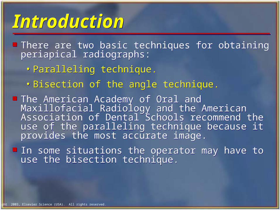
IntroductionIntroduction There are two basic techniques for obtaining
periapical radiographs:
• Paralleling technique.
• Bisection of the angle technique. The American Academy of Oral and Maxillofacial
Radiology and the American Association of Dental Schools recommend the use of the paralleling technique because it provides the most accurate image.
In some situations the operator may have to use the bisection technique.
There are two basic techniques for obtaining periapical radiographs:
• Paralleling technique.
• Bisection of the angle technique. The American Academy of Oral and Maxillofacial
Radiology and the American Association of Dental Schools recommend the use of the paralleling technique because it provides the most accurate image.
In some situations the operator may have to use the bisection technique.
Copyright 2003, Elsevier Science (USA). All rights reserved.
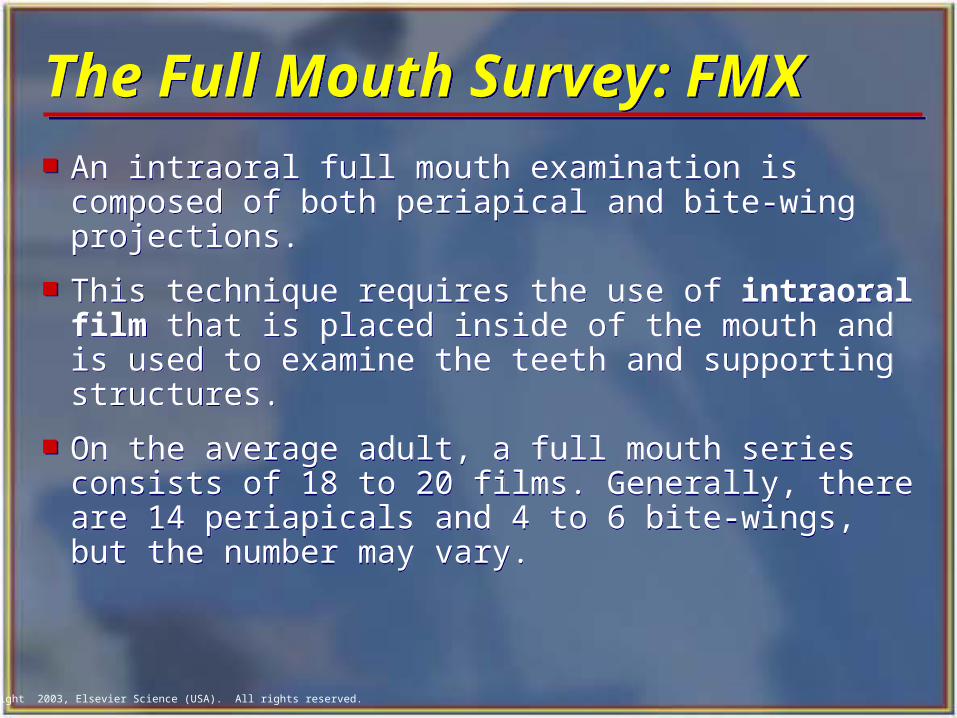
The Full Mouth Survey: FMXThe Full Mouth Survey: FMX An intraoral full mouth examination is composed
of both periapical and bite-wing projections.
This technique requires the use of intraoral film that is placed inside of the mouth and is used to examine the teeth and supporting structures.
On the average adult, a full mouth series consists of 18 to 20 films. Generally, there are 14 periapicals and 4 to 6 bite-wings, but the number may vary.
An intraoral full mouth examination is composed of both periapical and bite-wing projections.
This technique requires the use of intraoral film that is placed inside of the mouth and is used to examine the teeth and supporting structures.
On the average adult, a full mouth series consists of 18 to 20 films. Generally, there are 14 periapicals and 4 to 6 bite-wings, but the number may vary.
Copyright 2003, Elsevier Science (USA). All rights reserved.
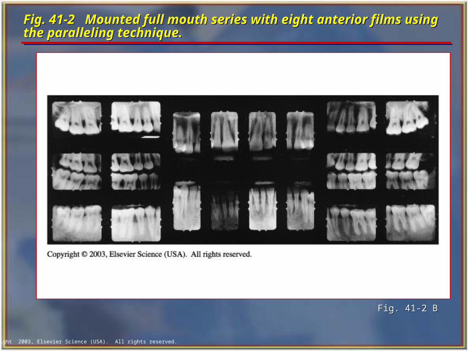
Fig. 41-2 Mounted full mouth series with eight anterior films using the paralleling technique.Fig. 41-2 Mounted full mouth series with eight anterior films using the paralleling technique.
Fig. 41-2 B Fig. 41-2 B
Copyright 2003, Elsevier Science (USA). All rights reserved.
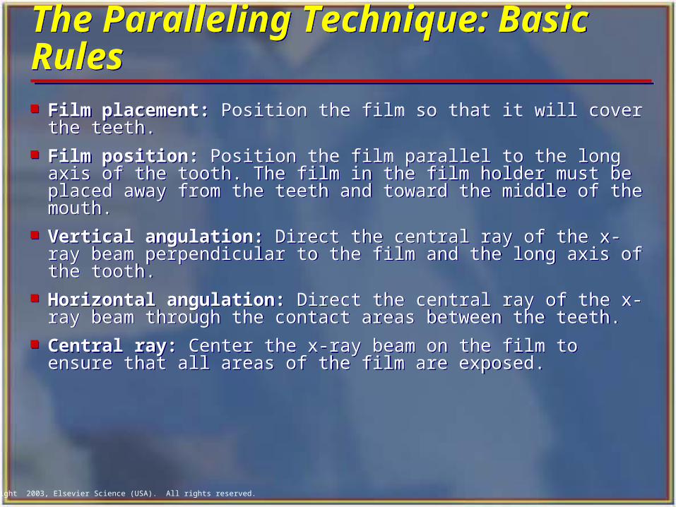
The Paralleling Technique: Basic RulesThe Paralleling Technique: Basic Rules Film placement: Position the film so that it will cover the
teeth. Film position: Position the film parallel to the long axis
of the tooth. The film in the film holder must be placed away from the teeth and toward the middle of the mouth.
Vertical angulation: Direct the central ray of the x-ray beam perpendicular to the film and the long axis of the tooth.
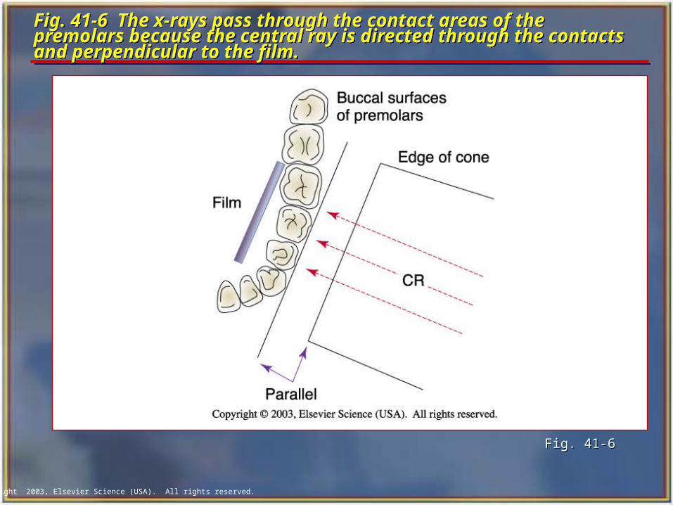
Horizontal angulation: Direct the central ray of the x-ray beam through the contact areas between the teeth.
Central ray: Center the x-ray beam on the film to ensure that all areas of the film are exposed.
Film placement: Position the film so that it will cover the teeth.
Film position: Position the film parallel to the long axis of the tooth. The film in the film holder must be placed away from the teeth and toward the middle of the mouth.
Vertical angulation: Direct the central ray of the x-ray beam perpendicular to the film and the long axis of the tooth.
Horizontal angulation: Direct the central ray of the x-ray beam through the contact areas between the teeth.
Central ray: Center the x-ray beam on the film to ensure that all areas of the film are exposed.
Copyright 2003, Elsevier Science (USA). All rights reserved.
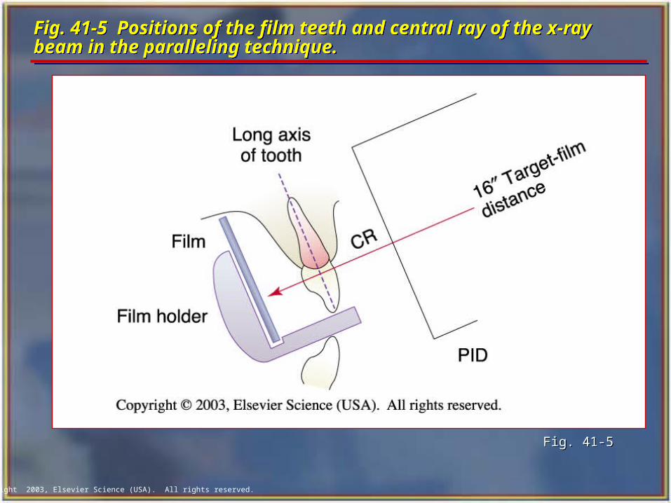
Fig. 41-5 Positions of the film teeth and central ray of the x-ray beam in the paralleling technique. Fig. 41-5 Positions of the film teeth and central ray of the x-ray beam in the paralleling technique.
Fig. 41-5Fig. 41-5
Copyright 2003, Elsevier Science (USA). All rights reserved.
Fig. 41-6 The x-rays pass through the contact areas of the premolars because the central ray is directed through the contacts and perpendicular to the film.
Fig. 41-6 The x-rays pass through the contact areas of the premolars because the central ray is directed through the contacts and perpendicular to the film.
Fig. 41-6Fig. 41-6
Copyright 2003, Elsevier Science (USA). All rights reserved.
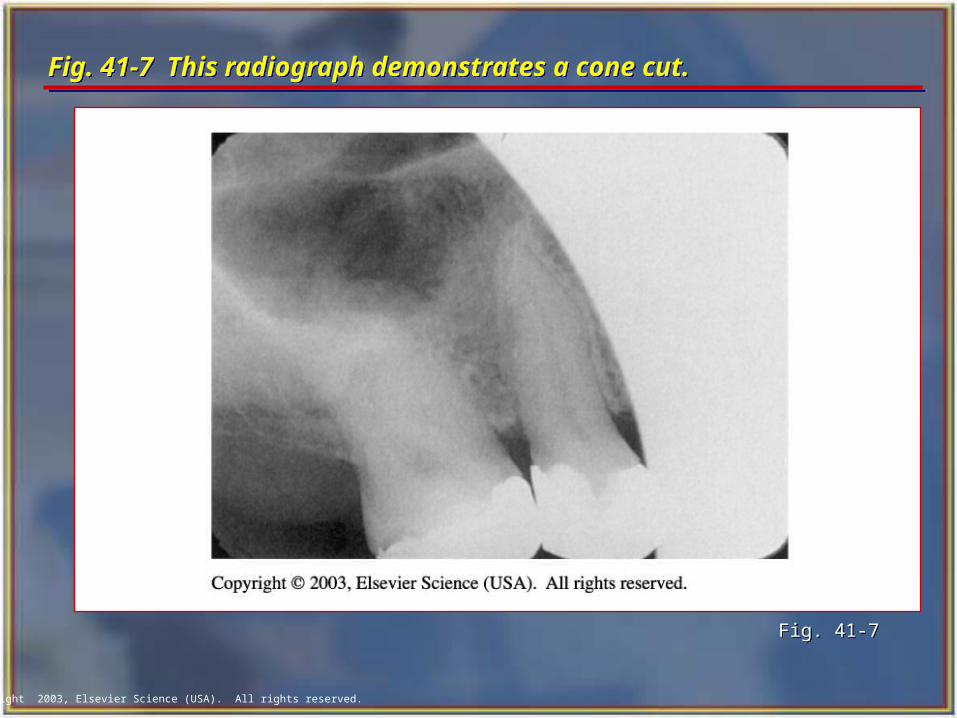
Fig. 41-7 This radiograph demonstrates a cone cut.Fig. 41-7 This radiograph demonstrates a cone cut.
Fig. 41-7Fig. 41-7
Copyright 2003, Elsevier Science (USA). All rights reserved.
Exposure Sequence Exposure Sequence
When exposing radiographs, establish an exposure sequence, or definite order for periapical film placement.
Without an exposure sequence, there is a good chance that you will omit an area or expose the same area twice.
When exposing radiographs, establish an exposure sequence, or definite order for periapical film placement.
Without an exposure sequence, there is a good chance that you will omit an area or expose the same area twice.
Copyright 2003, Elsevier Science (USA). All rights reserved.
Anterior Exposure Sequence Anterior Exposure Sequence When exposing periapical films with the
paralleling technique, always start with the anterior teeth (canines and incisors) because:
• The number 1 size film used for anteriors is small, less uncomfortable, and easier for the patient to tolerate.
• It is easier for the patient to become accustomed to the anterior film holder.
• The anterior film placements are less likely to cause the patient to gag.
When exposing periapical films with the paralleling technique, always start with the anterior teeth (canines and incisors) because:
• The number 1 size film used for anteriors is small, less uncomfortable, and easier for the patient to tolerate.
• It is easier for the patient to become accustomed to the anterior film holder.
• The anterior film placements are less likely to cause the patient to gag.
Copyright 2003, Elsevier Science (USA). All rights reserved.
Anterior Exposure Sequence cont’dAnterior Exposure Sequence cont’d Begin with the maxillary right canine (tooth #6).
Expose all of the maxillary anterior teeth from right to left.
End with the maxillary left canine (tooth #11).
Next, move to the mandibular arch.
Begin with the mandibular left canine (tooth #22).
Expose all of the mandibular anterior teeth from left to right.
Finish with the mandibular right canine (tooth #27).
Begin with the maxillary right canine (tooth #6).
Expose all of the maxillary anterior teeth from right to left.
End with the maxillary left canine (tooth #11).
Next, move to the mandibular arch.
Begin with the mandibular left canine (tooth #22).
Expose all of the mandibular anterior teeth from left to right.
Finish with the mandibular right canine (tooth #27).
Copyright 2003, Elsevier Science (USA). All rights reserved.
Posterior Exposure Sequence Posterior Exposure Sequence
After completing the anterior teeth, begin the posterior teeth.
Always expose the premolar film before the molar film because:
• Premolar film placement is easier for the patient to tolerate than molar film placement.
• Premolar exposure is less likely to evoke the gag reflex.
After completing the anterior teeth, begin the posterior teeth.
Always expose the premolar film before the molar film because:
• Premolar film placement is easier for the patient to tolerate than molar film placement.
• Premolar exposure is less likely to evoke the gag reflex.
Copyright 2003, Elsevier Science (USA). All rights reserved.
Tips for Film Placement Tips for Film Placement
The white side of the film always faces the teeth. The anterior films are always placed vertically. The posterior films are always placed horizontally. The identification dot on the film is always placed in
the slot of the film holder (dot in the slot). Always position the film holder away from the teeth
and toward the middle of the mouth. Always center the film over the areas to be examined. Always place the film parallel to the long axis of the
teeth.
Copyright 2003, Elsevier Science (USA). All rights reserved.
Preparation Before Seating the Patient Preparation Before Seating the Patient Prepare the operatory with all infection control barriers. Determine the number and type of films to be exposed. Label a paper cup with the patient's name and the date.
• This is the transfer cup for storing and moving exposed films.
Turn on the x-ray machine and check the basic settings. Wash and dry hands. Dispense the desired number of films and store them
outside of the room in which the x-ray machine is being used.
Prepare the operatory with all infection control barriers. Determine the number and type of films to be exposed. Label a paper cup with the patient's name and the date.
• This is the transfer cup for storing and moving exposed films.
Turn on the x-ray machine and check the basic settings. Wash and dry hands. Dispense the desired number of films and store them
outside of the room in which the x-ray machine is being used.
Copyright 2003, Elsevier Science (USA). All rights reserved.
Positioning the Patient Positioning the Patient Seat the patient comfortably in the dental chair, with the
back in an upright position and the head supported. Ask the patient to remove eyeglasses and bulky earrings. Have the patient remove any removable prosthetic
appliances from his or her mouth. Position the patient with the occlusal plane of the jaw
being radiographed parallel to the floor when the mouth is in the open position.
Drape the patient with a lead apron and thyroid collar. Wash and dry hands and put on clean examination
gloves.
Seat the patient comfortably in the dental chair, with the back in an upright position and the head supported.
Ask the patient to remove eyeglasses and bulky earrings. Have the patient remove any removable prosthetic
appliances from his or her mouth. Position the patient with the occlusal plane of the jaw
being radiographed parallel to the floor when the mouth is in the open position.
Drape the patient with a lead apron and thyroid collar. Wash and dry hands and put on clean examination
gloves.
Copyright 2003, Elsevier Science (USA). All rights reserved.
Maxillary Cuspid Region Maxillary Cuspid Region Insert the number 1 film packet vertically into
the anterior bite-block. Position the film packet with the cuspid and first
premolar centered. Position film as far posterior as possible.
With the film-holding instrument and film in place, instruct the patient to close the mouth slowly but firmly.
Position the localizing ring and positioning indicating device (PID), and then expose the film.
Insert the number 1 film packet vertically into the anterior bite-block.
Position the film packet with the cuspid and first premolar centered. Position film as far posterior as possible.
With the film-holding instrument and film in place, instruct the patient to close the mouth slowly but firmly.
Position the localizing ring and positioning indicating device (PID), and then expose the film.
Copyright 2003, Elsevier Science (USA). All rights reserved.
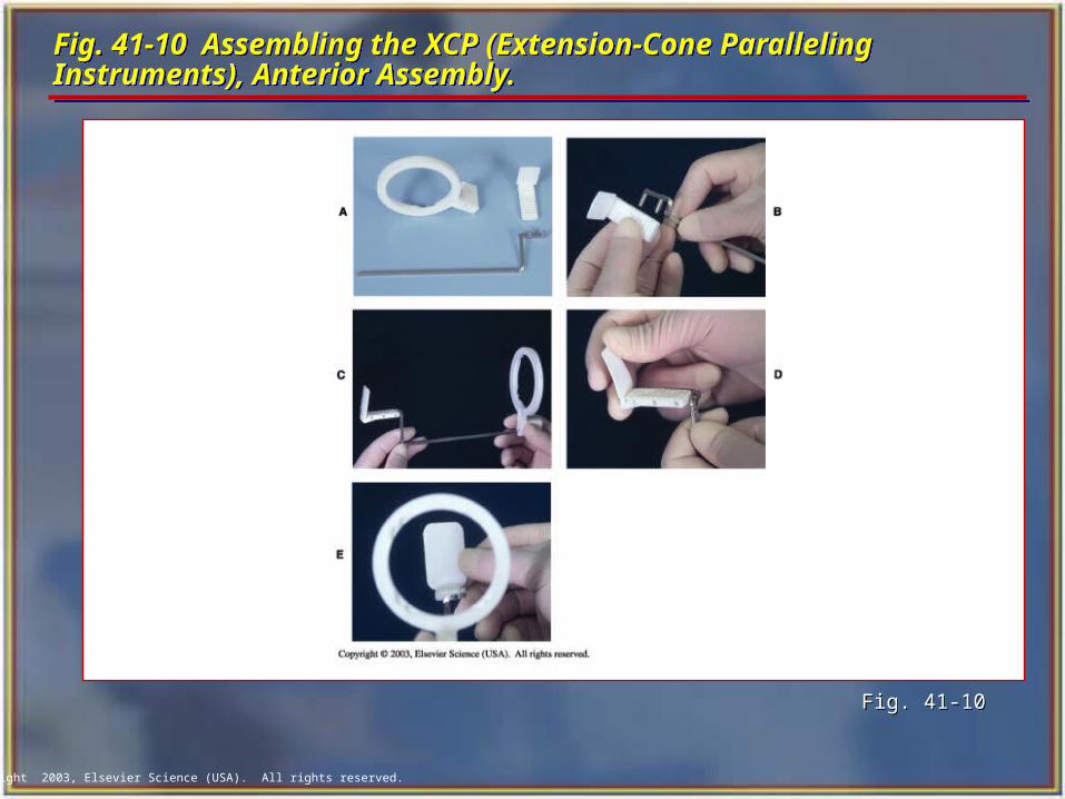
Fig. 41-10 Assembling the XCP (Extension-Cone Paralleling Instruments), Anterior Assembly.Fig. 41-10 Assembling the XCP (Extension-Cone Paralleling Instruments), Anterior Assembly.
Fig. 41-10Fig. 41-10
Copyright 2003, Elsevier Science (USA). All rights reserved.
Maxillary Central/Lateral Incisor Region Maxillary Central/Lateral Incisor Region
Insert the number 1 film packet vertically into the anterior bite-block.
Center the film packet between the central and lateral incisors and position the film as far posterior as possible.
With the film-holding instrument and film in place, instruct the patient to close the mouth slowly but firmly.
Position the localizing ring and PID and then expose the film.
Copyright 2003, Elsevier Science (USA). All rights reserved.
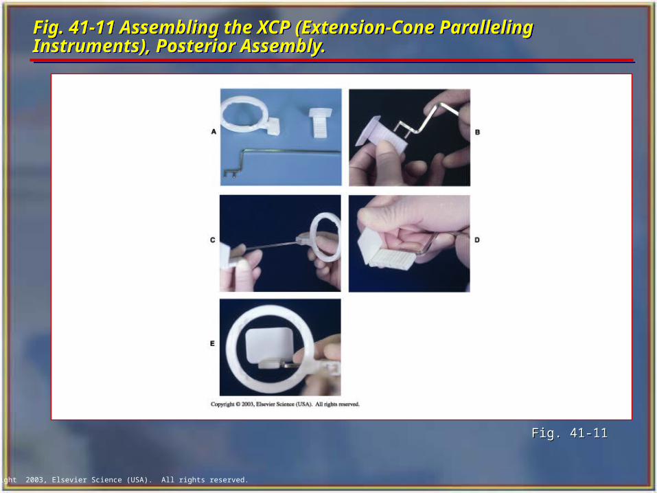
Fig. 41-11 Assembling the XCP (Extension-Cone Paralleling Instruments), Posterior Assembly.Fig. 41-11 Assembling the XCP (Extension-Cone Paralleling Instruments), Posterior Assembly.
Fig. 41-11Fig. 41-11
Copyright 2003, Elsevier Science (USA). All rights reserved.
Mandibular Cuspid Region Mandibular Cuspid Region Insert the number 1 film packet vertically
into the anterior bite-block. Center the film on the cuspid. Position the film as far in the lingual direction as the patient’s anatomy will allow.
A cotton roll may be placed between the maxillary teeth and bite-block to prevent rocking of the bite-block on the cuspid tip and to increase patient comfort.
Insert the number 1 film packet vertically into the anterior bite-block. Center the film on the cuspid. Position the film as far in the lingual direction as the patient’s anatomy will allow.
A cotton roll may be placed between the maxillary teeth and bite-block to prevent rocking of the bite-block on the cuspid tip and to increase patient comfort.
Copyright 2003, Elsevier Science (USA). All rights reserved.
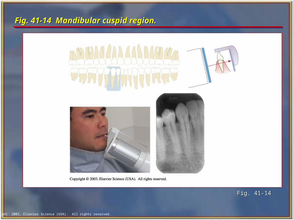
Fig. 41-14 Mandibular cuspid region. Fig. 41-14 Mandibular cuspid region.
Fig. 41-14Fig. 41-14
Copyright 2003, Elsevier Science (USA). All rights reserved.
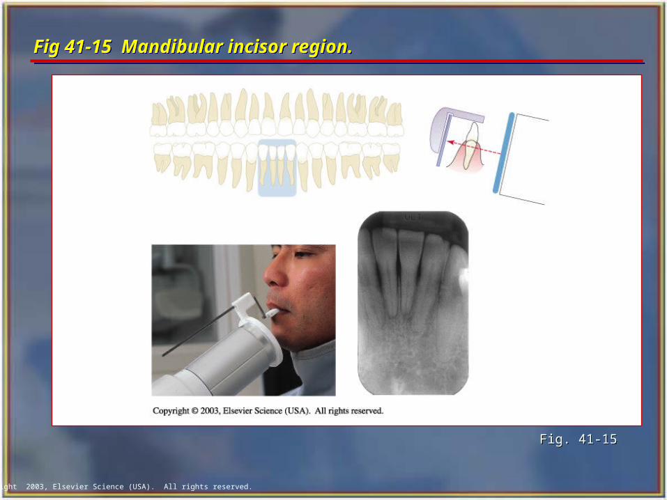
Mandibular Incisor Region Mandibular Incisor Region Insert the number 1 film packet vertically into
the anterior bite-block. Center the film packet between the central
and lateral incisors and position the film as far in the lingual direction as the patient's anatomy will allow.
With the instrument and film in place, instruct the patient to close the mouth slowly but firmly.
Position the localizing ring and PID and then expose the film.
Insert the number 1 film packet vertically into the anterior bite-block.
Center the film packet between the central and lateral incisors and position the film as far in the lingual direction as the patient's anatomy will allow.
With the instrument and film in place, instruct the patient to close the mouth slowly but firmly.
Position the localizing ring and PID and then expose the film.
Copyright 2003, Elsevier Science (USA). All rights reserved.
Fig 41-15 Mandibular incisor region. Fig 41-15 Mandibular incisor region.
Fig. 41-15Fig. 41-15
Copyright 2003, Elsevier Science (USA). All rights reserved.
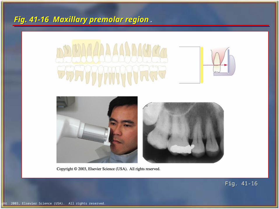
Maxillary Premolar Region Maxillary Premolar Region
Insert the film packet horizontally into the posterior bite-block, pushing the film packet all the way into the slot.
Center the film packet on the second premolar. Position film in the midpalate area.
With the instrument and film in place, instruct the patient to close the mouth slowly but firmly.
Position the localizing ring and PID and then expose the film.
Copyright 2003, Elsevier Science (USA). All rights reserved.
Fig. 41-16 Maxillary premolar region.Fig. 41-16 Maxillary premolar region.
Fig. 41-16Fig. 41-16
Copyright 2003, Elsevier Science (USA). All rights reserved.
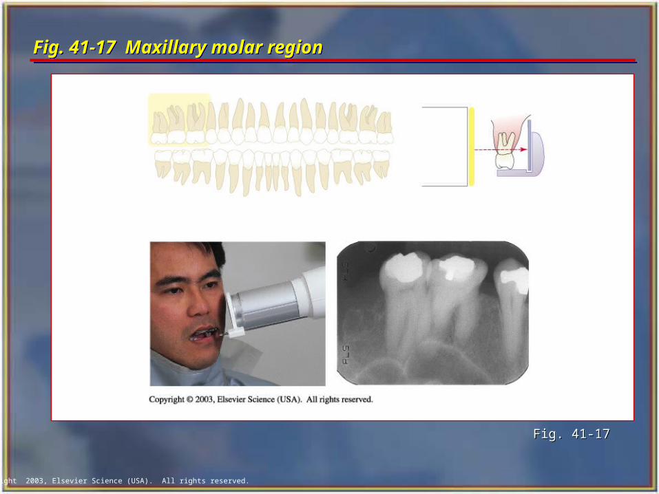
Maxillary Molar Region Maxillary Molar Region
Insert the film packet horizontally into the posterior bite-block.
Center the film packet on the second molar. Position the film in the midpalate area.
With the instrument and film in place, instruct the patient to close the mouth slowly but firmly.
Position the localizing ring and PID and then expose the radiograph.
Copyright 2003, Elsevier Science (USA). All rights reserved.
Fig. 41-17 Maxillary molar region Fig. 41-17 Maxillary molar region
Fig. 41-17Fig. 41-17
Copyright 2003, Elsevier Science (USA). All rights reserved.
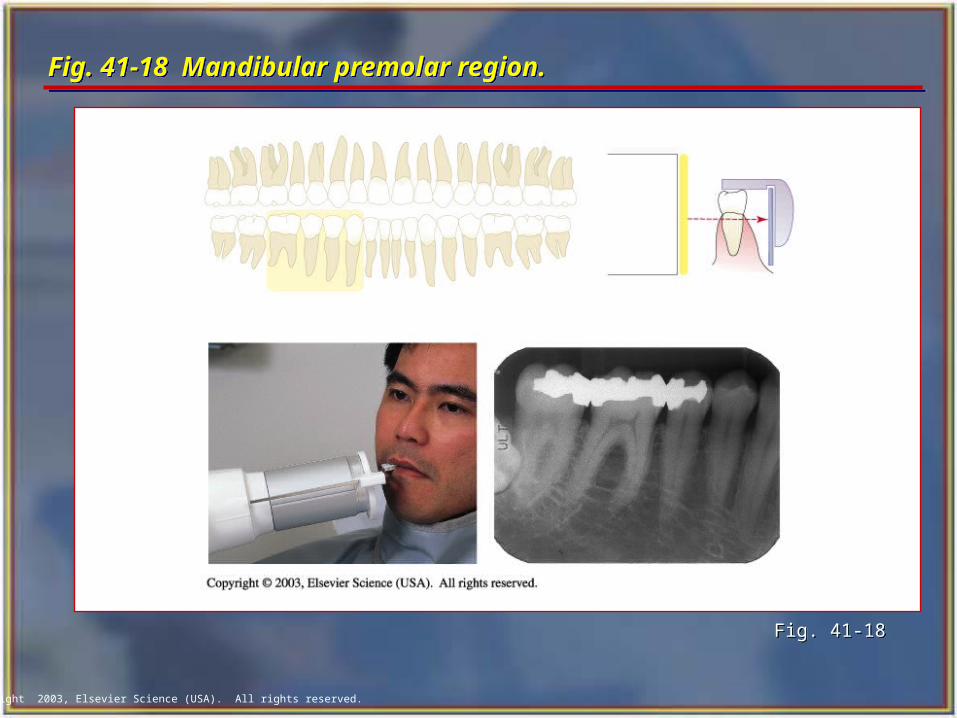
Mandibular Premolar Region Mandibular Premolar Region Insert the number 2 film horizontally into the
posterior bite-block. Center the film on the contact point between the
second premolar and first molar. Position the film as far in the lingual direction as the patient's anatomy will allow.
With the instrument and film in place, instruct the patient to close the mouth slowly but firmly.
Slide the localizing ring down the indicator rod to the patient's skin surface.
Position the localizing ring and PID and then expose the film.
Insert the number 2 film horizontally into the posterior bite-block.
Center the film on the contact point between the second premolar and first molar. Position the film as far in the lingual direction as the patient's anatomy will allow.
With the instrument and film in place, instruct the patient to close the mouth slowly but firmly.
Slide the localizing ring down the indicator rod to the patient's skin surface.
Position the localizing ring and PID and then expose the film.
Copyright 2003, Elsevier Science (USA). All rights reserved.
Fig. 41-18 Mandibular premolar region.Fig. 41-18 Mandibular premolar region.
Fig. 41-18Fig. 41-18
Copyright 2003, Elsevier Science (USA). All rights reserved.
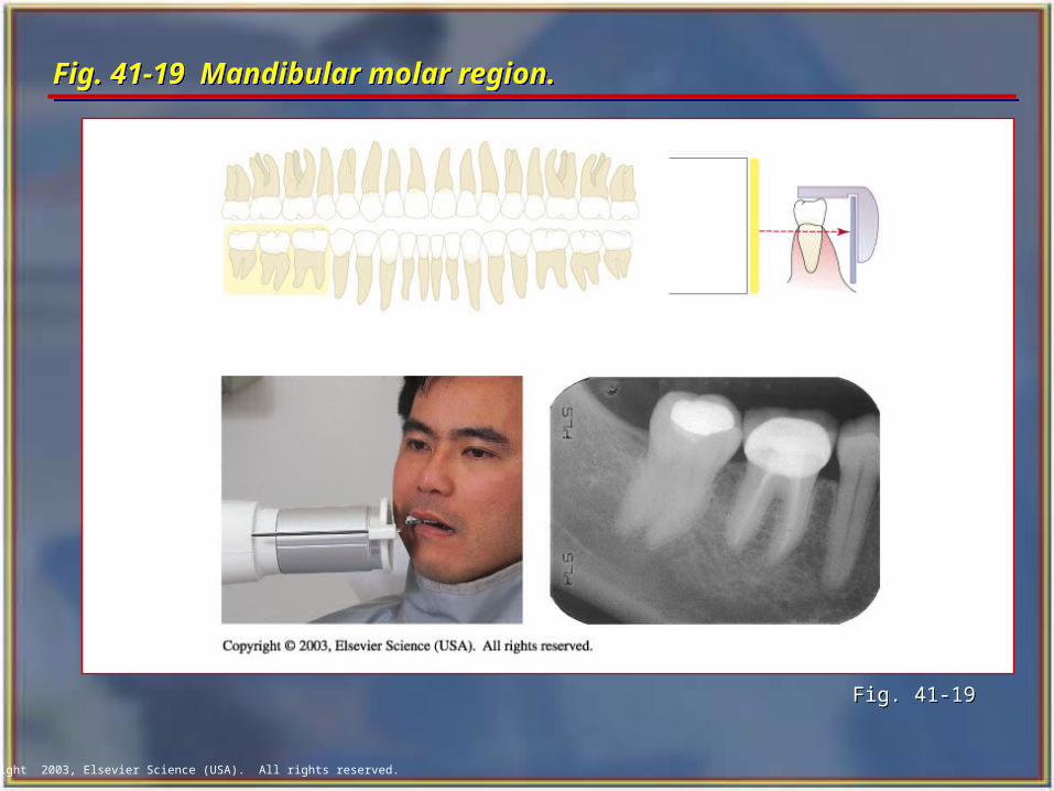
Mandibular Molar RegionMandibular Molar Region Insert the number 2 film horizontally into the
posterior bite-block. Center the film on the second molar. Position the
film as far in the lingual direction as the tongue will allow. This position will be closer to the teeth than that for the premolar and anterior views.
With the instrument and film in place, instruct the patient to close the mouth slowly but firmly.
Position the localizing ring and PID and then expose the film.
Insert the number 2 film horizontally into the posterior bite-block.
Center the film on the second molar. Position the film as far in the lingual direction as the tongue will allow. This position will be closer to the teeth than that for the premolar and anterior views.
With the instrument and film in place, instruct the patient to close the mouth slowly but firmly.
Position the localizing ring and PID and then expose the film.
Copyright 2003, Elsevier Science (USA). All rights reserved.
Fig. 41-19 Mandibular molar region.Fig. 41-19 Mandibular molar region.
Fig. 41-19Fig. 41-19
Copyright 2003, Elsevier Science (USA). All rights reserved.
The Bisecting Technique The Bisecting Technique
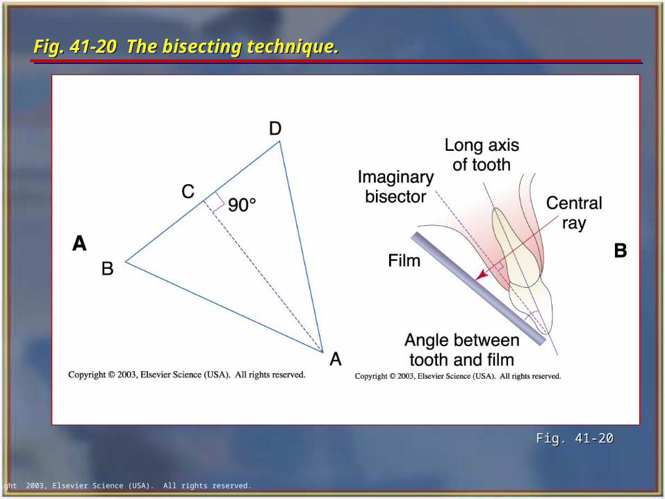
The bisection of the angle technique is based on a geometric principle of bisecting a triangle (bisecting means dividing into two equal parts).
The angle formed by the long axis of the teeth and the film is bisected, and the x-ray beam is directed perpendicular to the bisecting line.
Perpendicular means at a right angle to the film.
Copyright 2003, Elsevier Science (USA). All rights reserved.
Fig. 41-20 The bisecting technique. Fig. 41-20 The bisecting technique.
Fig. 41-20 Fig. 41-20
Copyright 2003, Elsevier Science (USA). All rights reserved.
Film Holders Film Holders Although you may see operators asking the
patients to hold the film with their fingers to stabilize the film in the mouth, it is not recommended. This practice exposes the patient's hand and finger to unnecessary radiation.
The following are types of commercial film holders that are available:
• Rinn BAI Instruments
• EEZEE-Grip Film Holder (Snap-A-Ray)
• Stabe Bite-Block (Rinn Corporation)
Although you may see operators asking the patients to hold the film with their fingers to stabilize the film in the mouth, it is not recommended. This practice exposes the patient's hand and finger to unnecessary radiation.
The following are types of commercial film holders that are available:
• Rinn BAI Instruments
• EEZEE-Grip Film Holder (Snap-A-Ray)
• Stabe Bite-Block (Rinn Corporation)
Copyright 2003, Elsevier Science (USA). All rights reserved.
PID Angulations: Bisecting TechniquePID Angulations: Bisecting Technique In the bisecting technique, the angulation of the
PID is critical.
Angulation is a term used to describe the alignment of the central ray of the x-ray beam in the horizontal and vertical planes.
Angulation can be changed by moving the PID in either a horizontal or vertical direction.
The bisecting angle instruments (BAI) with aiming rings dictates the proper PID angulation.
In the bisecting technique, the angulation of the PID is critical.
Angulation is a term used to describe the alignment of the central ray of the x-ray beam in the horizontal and vertical planes.
Angulation can be changed by moving the PID in either a horizontal or vertical direction.
The bisecting angle instruments (BAI) with aiming rings dictates the proper PID angulation.
Copyright 2003, Elsevier Science (USA). All rights reserved.
Horizontal AngulationHorizontal Angulation
Horizontal angulation refers to the positioning of the tubehead and direction of the central ray in a horizontal, or side-to-side, plane.
The horizontal angulation remains the same whether you are using the paralleling or bisecting technique.
Horizontal angulation refers to the positioning of the tubehead and direction of the central ray in a horizontal, or side-to-side, plane.
The horizontal angulation remains the same whether you are using the paralleling or bisecting technique.
Copyright 2003, Elsevier Science (USA). All rights reserved.
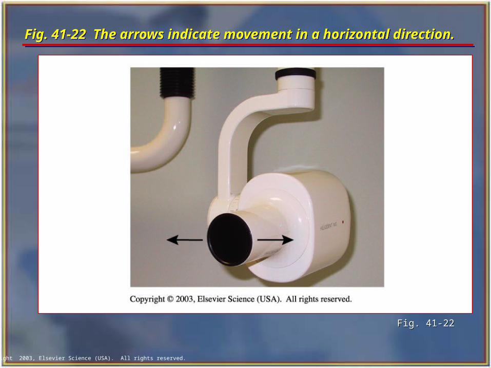
Fig. 41-22 The arrows indicate movement in a horizontal direction.Fig. 41-22 The arrows indicate movement in a horizontal direction.
Fig. 41-22Fig. 41-22
Copyright 2003, Elsevier Science (USA). All rights reserved.
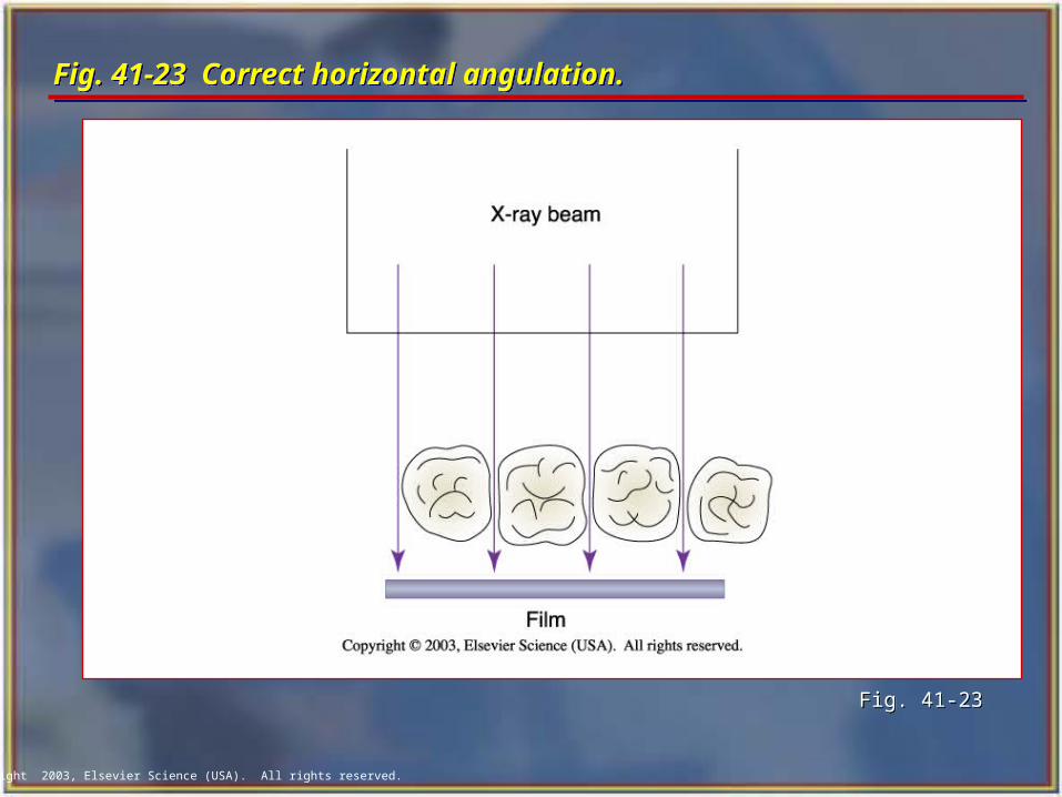
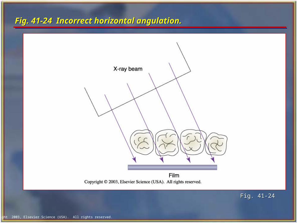
Correct Horizontal AngulationCorrect Horizontal Angulation
With correct horizontal angulation, the central ray is directed perpendicular to the curvature of the arch and through the contact areas of the teeth.
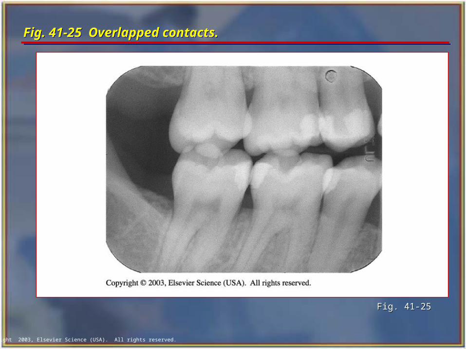
Incorrect horizontal angulation results in overlapped (unopened) contact areas.
A film with overlapped contact areas cannot be used to examine the interproximal areas of the teeth.
With correct horizontal angulation, the central ray is directed perpendicular to the curvature of the arch and through the contact areas of the teeth.
Incorrect horizontal angulation results in overlapped (unopened) contact areas.
A film with overlapped contact areas cannot be used to examine the interproximal areas of the teeth.
Copyright 2003, Elsevier Science (USA). All rights reserved.
Fig. 41-23 Correct horizontal angulation.Fig. 41-23 Correct horizontal angulation.
Fig. 41-23Fig. 41-23
Copyright 2003, Elsevier Science (USA). All rights reserved.
Fig. 41-24 Incorrect horizontal angulation.Fig. 41-24 Incorrect horizontal angulation.
Fig. 41-24Fig. 41-24
Copyright 2003, Elsevier Science (USA). All rights reserved.
Fig. 41-25 Overlapped contacts.Fig. 41-25 Overlapped contacts.
Fig. 41-25Fig. 41-25
Copyright 2003, Elsevier Science (USA). All rights reserved.
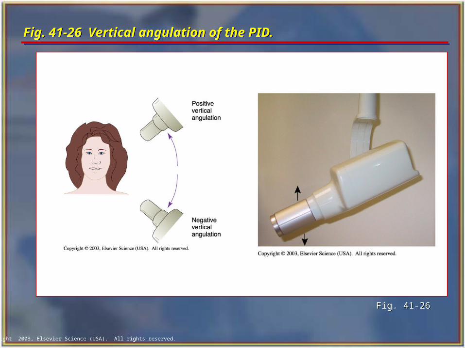
Vertical Angulation Vertical Angulation
Vertical angulation refers to the positioning of the PID in a vertical, or up-and-down, plane.
The vertical angulation differs according to the radiographic technique being used:
• With the paralleling technique, the vertical angulation of the central ray is directed perpendicular to the film and the long axis of the tooth.
• With the bisecting technique, the vertical angulation is determined by the imaginary bisector; the central ray is directed perpendicular to the imaginary bisector.
Copyright 2003, Elsevier Science (USA). All rights reserved.
Fig. 41-26 Vertical angulation of the PID. Fig. 41-26 Vertical angulation of the PID.
Fig. 41-26Fig. 41-26
Copyright 2003, Elsevier Science (USA). All rights reserved.
Correct Vertical Angulation Correct Vertical Angulation
Correct vertical angulation results in a radiographic image that is the same length as the tooth.
Incorrect vertical angulation results in an image that is not the same length as the tooth being radiographed.
The image appears either longer or shorter:
• Elongated
• Foreshortened
Correct vertical angulation results in a radiographic image that is the same length as the tooth.
Incorrect vertical angulation results in an image that is not the same length as the tooth being radiographed.
The image appears either longer or shorter:
• Elongated
• Foreshortened
Copyright 2003, Elsevier Science (USA). All rights reserved.
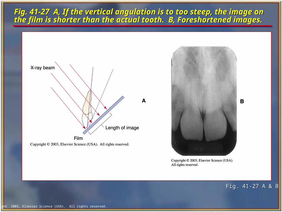
Fig. 41-27 A, If the vertical angulation is to too steep, the image on the film is shorter than the actual tooth. B, Foreshortened images. Fig. 41-27 A, If the vertical angulation is to too steep, the image on the film is shorter than the actual tooth. B, Foreshortened images.
Fig. 41-27 A & BFig. 41-27 A & B
Copyright 2003, Elsevier Science (USA). All rights reserved.
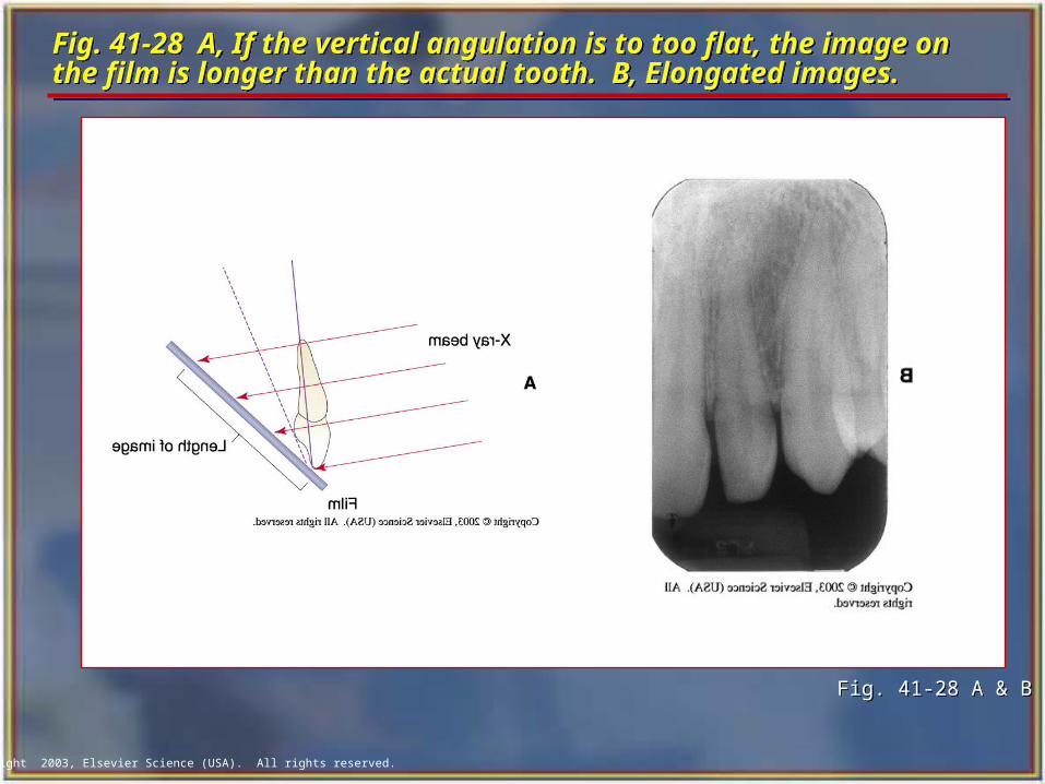
Fig. 41-28 A, If the vertical angulation is to too flat, the image on the film is longer than the actual tooth. B, Elongated images.Fig. 41-28 A, If the vertical angulation is to too flat, the image on the film is longer than the actual tooth. B, Elongated images.
Fig. 41-28 A & BFig. 41-28 A & B
Copyright 2003, Elsevier Science (USA). All rights reserved.
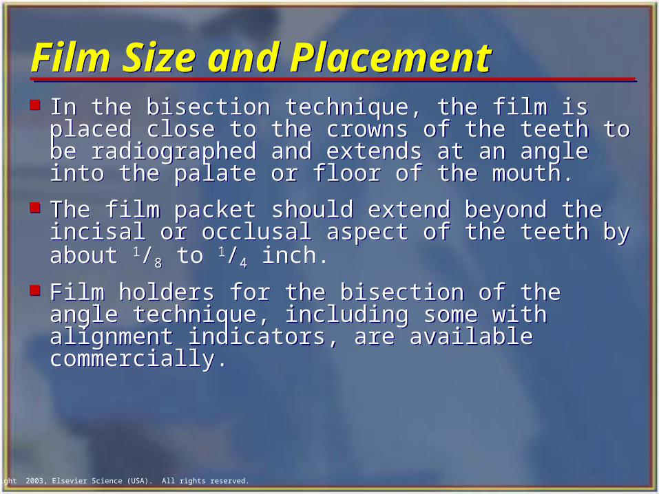
Film Size and Placement Film Size and Placement In the bisection technique, the film is placed
close to the crowns of the teeth to be radiographed and extends at an angle into the palate or floor of the mouth.
The film packet should extend beyond the incisal or occlusal aspect of the teeth by about 1/8 to 1/4 inch.
Film holders for the bisection of the angle technique, including some with alignment indicators, are available commercially.
In the bisection technique, the film is placed close to the crowns of the teeth to be radiographed and extends at an angle into the palate or floor of the mouth.
The film packet should extend beyond the incisal or occlusal aspect of the teeth by about 1/8 to 1/4 inch.
Film holders for the bisection of the angle technique, including some with alignment indicators, are available commercially.
Copyright 2003, Elsevier Science (USA). All rights reserved.
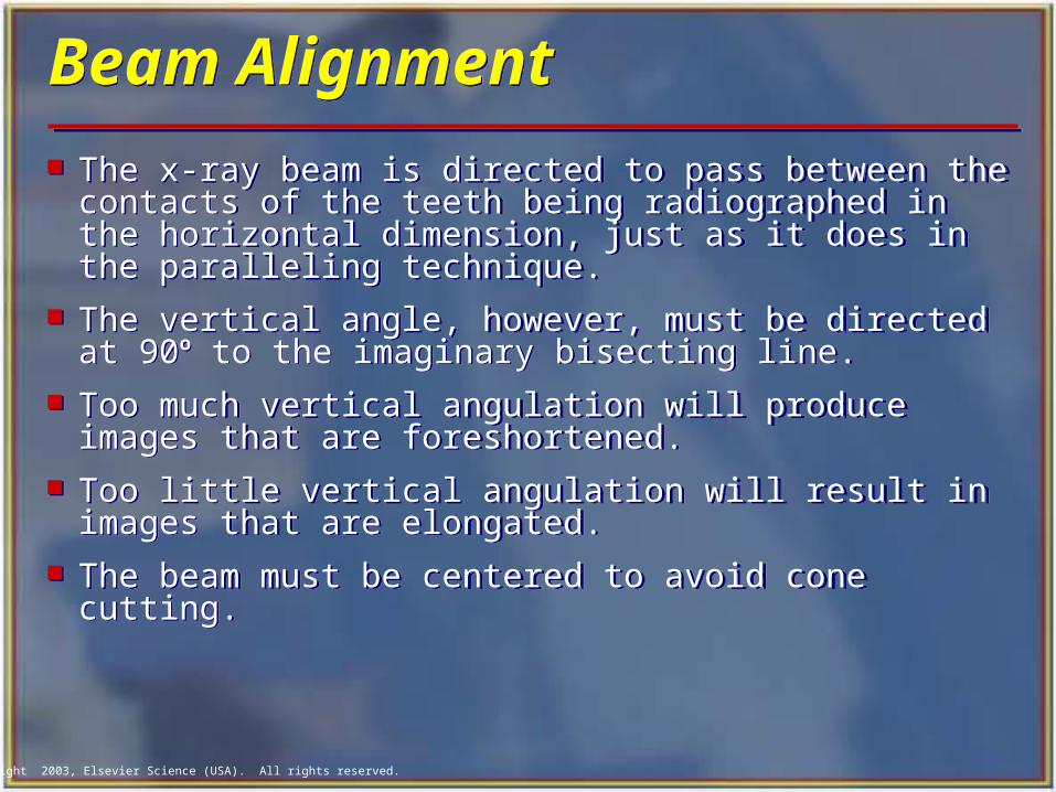
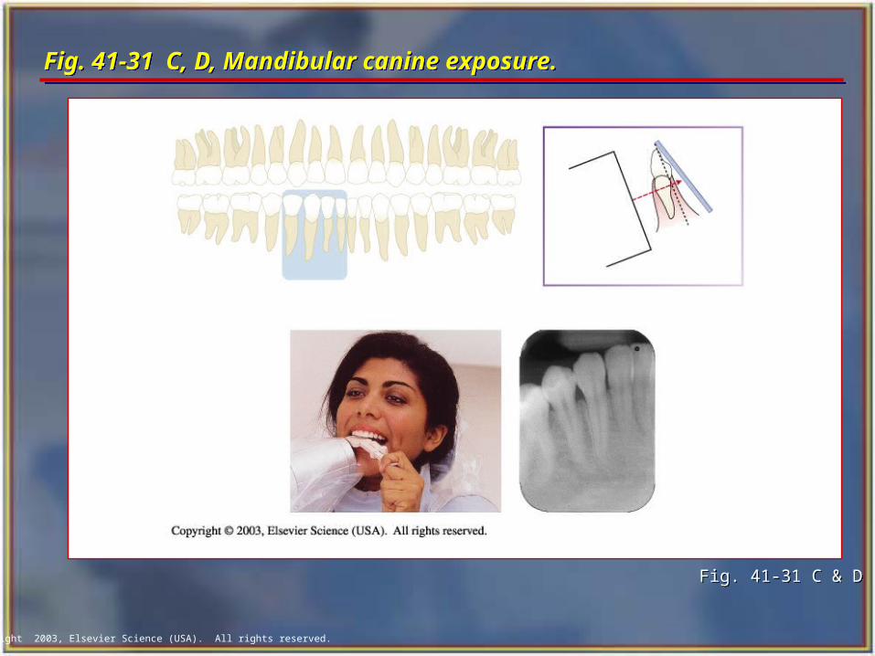
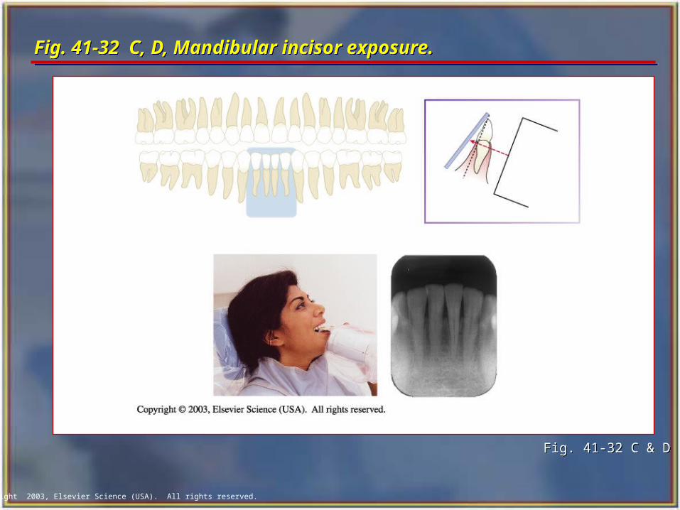
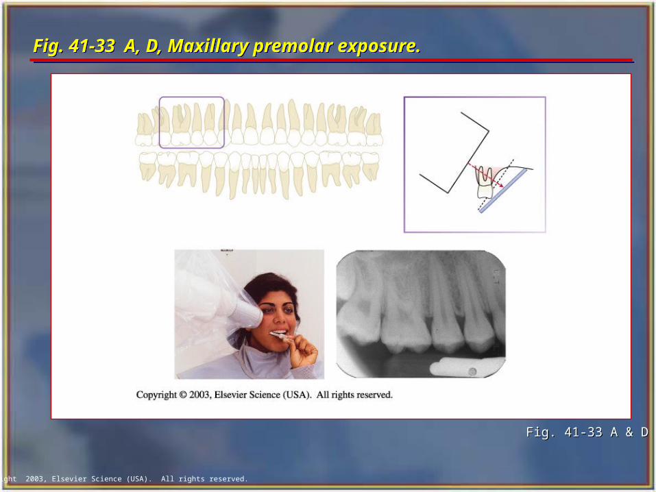
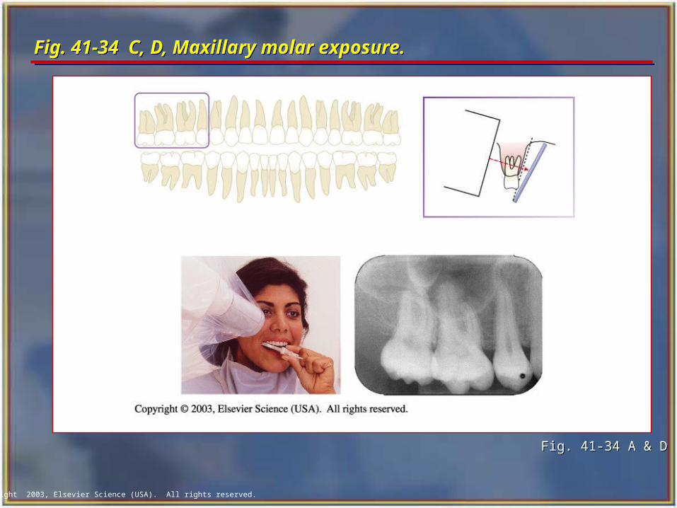
Beam Alignment Beam Alignment
The x-ray beam is directed to pass between the contacts of the teeth being radiographed in the horizontal dimension, just as it does in the paralleling technique.
The vertical angle, however, must be directed at 90o to the imaginary bisecting line.
Too much vertical angulation will produce images that are foreshortened.
Too little vertical angulation will result in images that are elongated.
The beam must be centered to avoid cone cutting.
Copyright 2003, Elsevier Science (USA). All rights reserved.
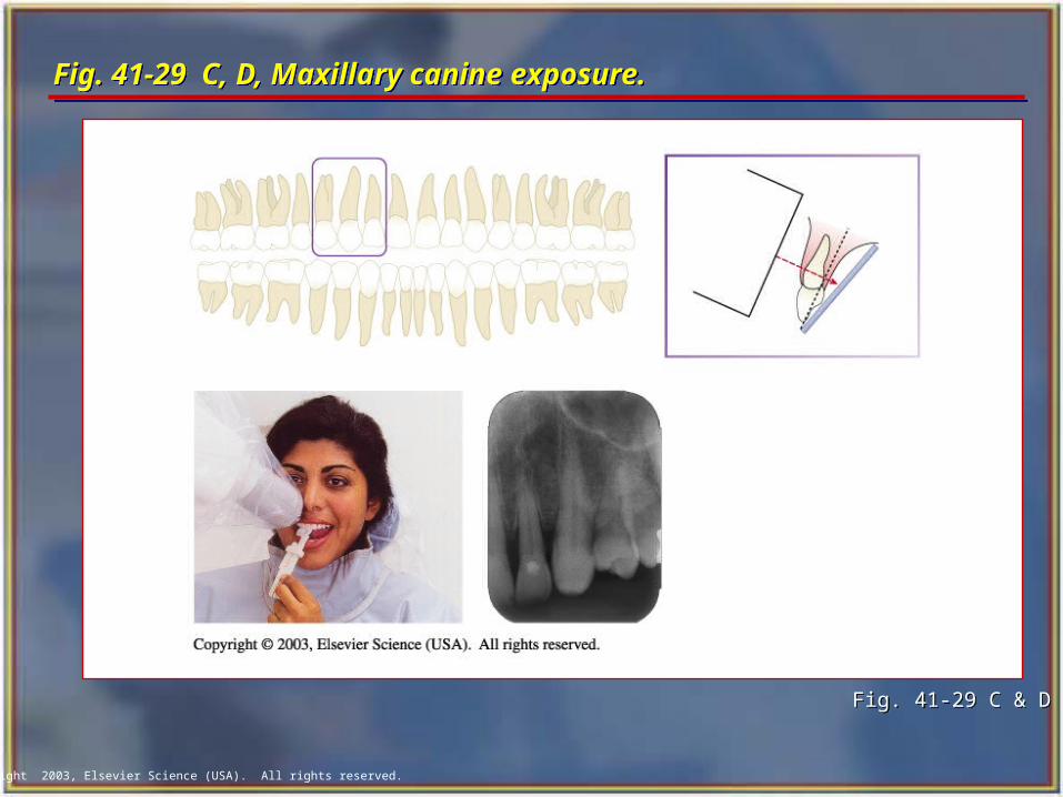
Fig. 41-29 C, D, Maxillary canine exposure. Fig. 41-29 C, D, Maxillary canine exposure.
Fig. 41-29 C & DFig. 41-29 C & D
Copyright 2003, Elsevier Science (USA). All rights reserved.
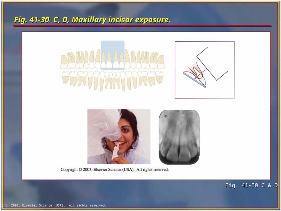
Fig. 41-30 C, D, Maxillary incisor exposure.Fig. 41-30 C, D, Maxillary incisor exposure.
Fig. 41-30 C & DFig. 41-30 C & D
Copyright 2003, Elsevier Science (USA). All rights reserved.
Fig. 41-31 C, D, Mandibular canine exposure. Fig. 41-31 C, D, Mandibular canine exposure.
Fig. 41-31 C & D Fig. 41-31 C & D
Copyright 2003, Elsevier Science (USA). All rights reserved.
Fig. 41-32 C, D, Mandibular incisor exposure. Fig. 41-32 C, D, Mandibular incisor exposure.
Fig. 41-32 C & D Fig. 41-32 C & D
Copyright 2003, Elsevier Science (USA). All rights reserved.
Fig. 41-33 A, D, Maxillary premolar exposure. Fig. 41-33 A, D, Maxillary premolar exposure.
Fig. 41-33 A & DFig. 41-33 A & D
Copyright 2003, Elsevier Science (USA). All rights reserved.
Fig. 41-34 C, D, Maxillary molar exposure. Fig. 41-34 C, D, Maxillary molar exposure.
Fig. 41-34 A & D Fig. 41-34 A & D
Copyright 2003, Elsevier Science (USA). All rights reserved.
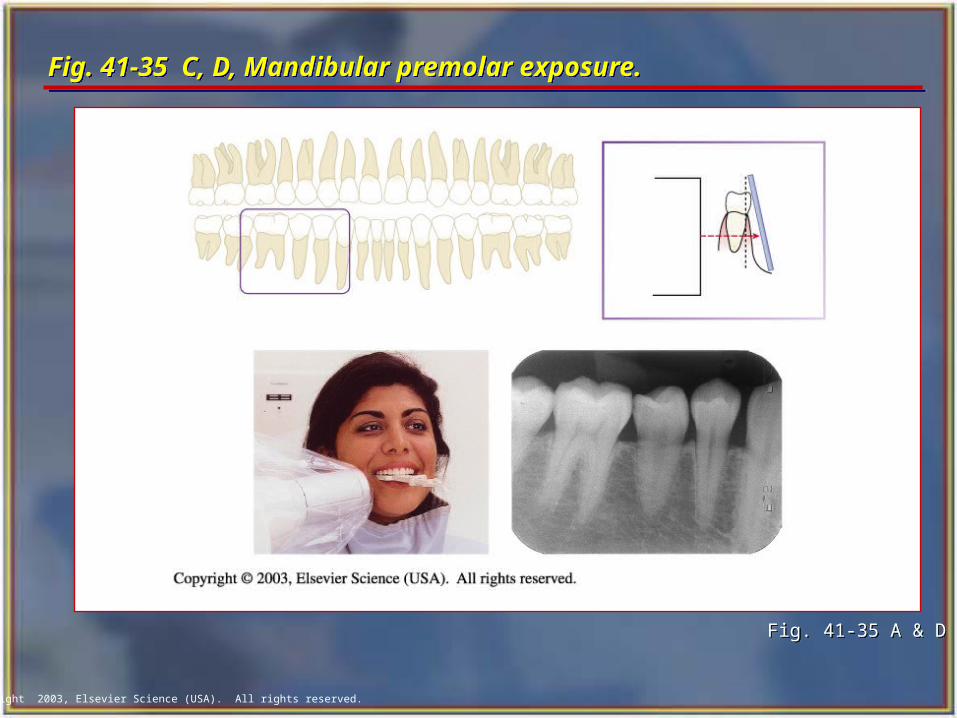
Fig. 41-35 C, D, Mandibular premolar exposure. Fig. 41-35 C, D, Mandibular premolar exposure.
Fig. 41-35 A & DFig. 41-35 A & D
Copyright 2003, Elsevier Science (USA). All rights reserved.
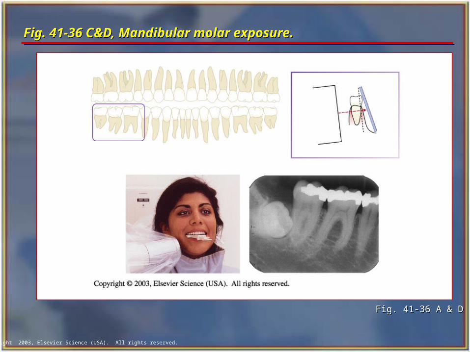
Fig. 41-36 C&D, Mandibular molar exposure. Fig. 41-36 C&D, Mandibular molar exposure.
Fig. 41-36 A & D Fig. 41-36 A & D
Copyright 2003, Elsevier Science (USA). All rights reserved.
Bite-wing Examinations Bite-wing Examinations A bite-wing radiograph shows the crowns
and interproximal areas of the maxillary and mandibular teeth and the areas of crestal bone on one film.
Bite-wing radiographs are used to detect interproximal caries (tooth decay) and are particularly useful in detecting early carious lesions that are not clinically evident.
Bite-wing radiographs are also useful in examining the crestal bone levels between the teeth.
A bite-wing radiograph shows the crowns and interproximal areas of the maxillary and mandibular teeth and the areas of crestal bone on one film.
Bite-wing radiographs are used to detect interproximal caries (tooth decay) and are particularly useful in detecting early carious lesions that are not clinically evident.
Bite-wing radiographs are also useful in examining the crestal bone levels between the teeth.
Copyright 2003, Elsevier Science (USA). All rights reserved.
Basic Principles of the Bite-wing Technique Basic Principles of the Bite-wing Technique
The film is placed in the mouth parallel to the crowns of both the upper and lower teeth.
The film is stabilized when the patient bites on the bite-wing tab or bite-wing film holder.
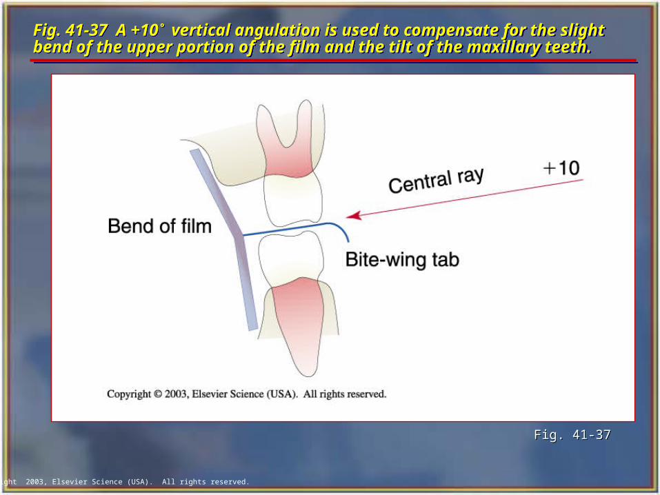
The central ray of the x-ray beam is directed through the contacts of the teeth, using a +10˚ vertical angulation.
The film is placed in the mouth parallel to the crowns of both the upper and lower teeth.
The film is stabilized when the patient bites on the bite-wing tab or bite-wing film holder.
The central ray of the x-ray beam is directed through the contacts of the teeth, using a +10˚ vertical angulation.
Copyright 2003, Elsevier Science (USA). All rights reserved.
Fig. 41-37 A +10˚ vertical angulation is used to compensate for the slight bend of the upper portion of the film and the tilt of the maxillary teeth.Fig. 41-37 A +10˚ vertical angulation is used to compensate for the slight bend of the upper portion of the film and the tilt of the maxillary teeth.
Fig. 41-37Fig. 41-37
Copyright 2003, Elsevier Science (USA). All rights reserved.
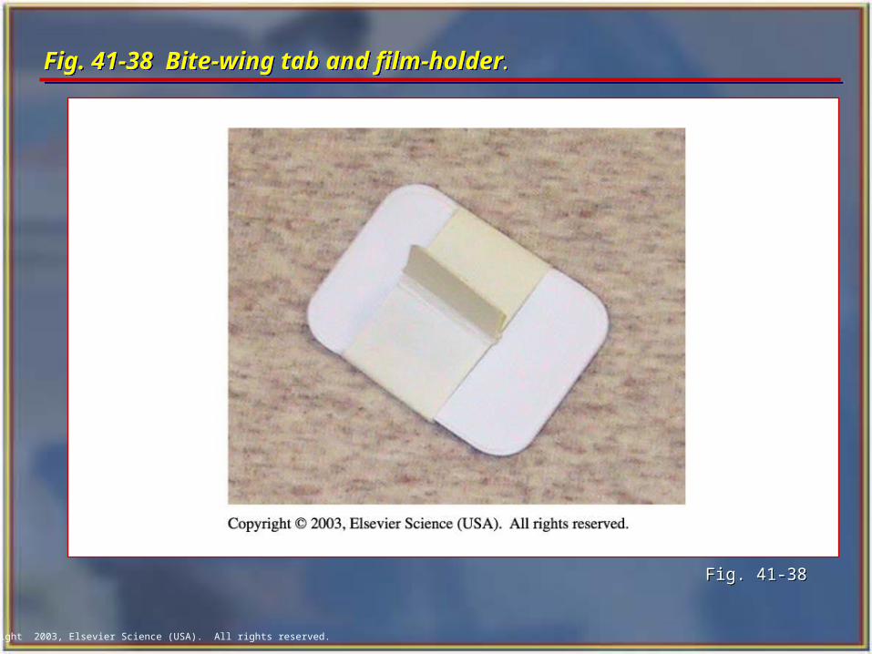
Fig. 41-38 Bite-wing tab and film-holder.Fig. 41-38 Bite-wing tab and film-holder.
Fig. 41-38Fig. 41-38
Copyright 2003, Elsevier Science (USA). All rights reserved.
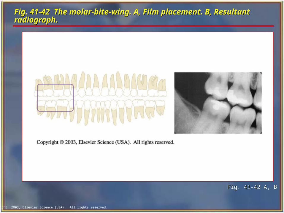
BWX Film PlacementBWX Film Placement The film is positioned (with either a bite tab or
a film-holding device) parallel to the crowns of both upper and lower teeth, and the central ray is directed perpendicular to the film.
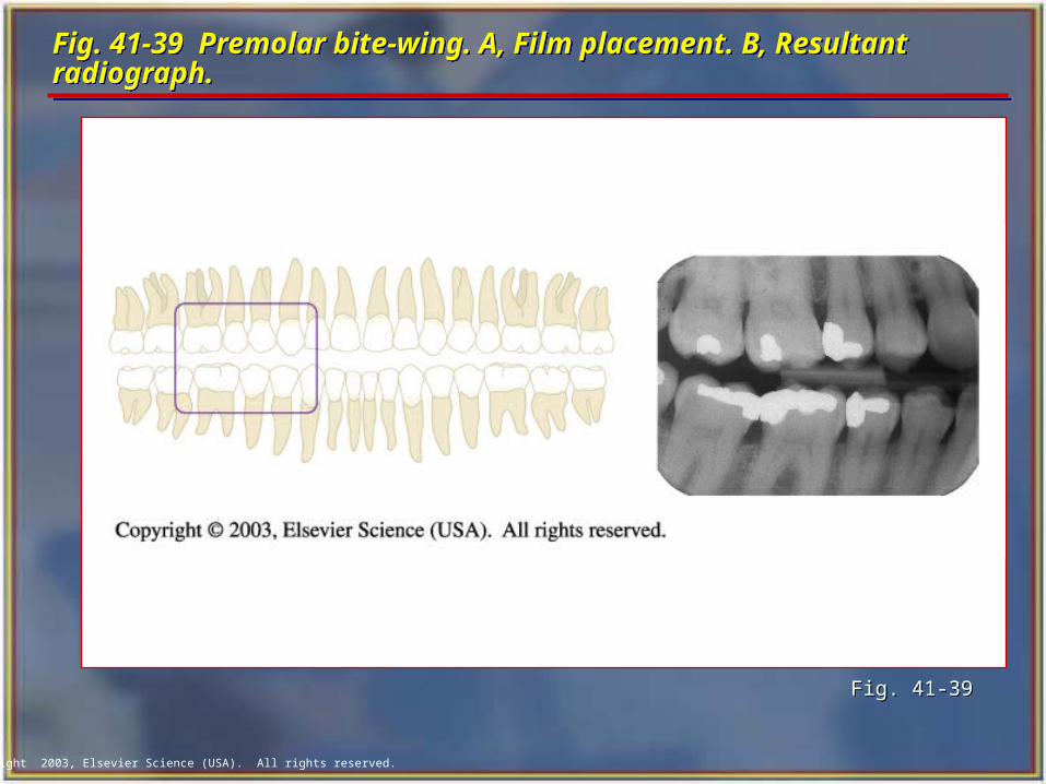
The premolar bite-wing radiograph should include the distal half of the crowns of the cuspids, both premolars, and often the first molars on both the maxillary and mandibular arches.
The molar film should be centered over the second molars.
The film is positioned (with either a bite tab or a film-holding device) parallel to the crowns of both upper and lower teeth, and the central ray is directed perpendicular to the film.
The premolar bite-wing radiograph should include the distal half of the crowns of the cuspids, both premolars, and often the first molars on both the maxillary and mandibular arches.
The molar film should be centered over the second molars.
Copyright 2003, Elsevier Science (USA). All rights reserved.
Fig. 41-39 Premolar bite-wing. A, Film placement. B, Resultant radiograph.Fig. 41-39 Premolar bite-wing. A, Film placement. B, Resultant radiograph.
Fig. 41-39Fig. 41-39
Copyright 2003, Elsevier Science (USA). All rights reserved.
Fig. 41-42 The molar-bite-wing. A, Film placement. B, Resultant radiograph.Fig. 41-42 The molar-bite-wing. A, Film placement. B, Resultant radiograph.
Fig. 41-42 A, BFig. 41-42 A, B
Copyright 2003, Elsevier Science (USA). All rights reserved.
The Occlusal TechniqueThe Occlusal Technique The occlusal technique is used to examine
large areas of the upper or lower jaw.
In the occlusal technique, size-4 intraoral film is used. The film is so named because the patient bites, or “occludes,” on the entire film.
In adults, size-4 film is used in the occlusal examination.
In children, size-2 film can be used.
The occlusal technique is used to examine large areas of the upper or lower jaw.
In the occlusal technique, size-4 intraoral film is used. The film is so named because the patient bites, or “occludes,” on the entire film.
In adults, size-4 film is used in the occlusal examination.
In children, size-2 film can be used.
Copyright 2003, Elsevier Science (USA). All rights reserved.
Basic Principles of the Occlusal TechniqueBasic Principles of the Occlusal Technique
The film is positioned with the white side facing the arch being exposed.
The film is placed in the mouth between the occlusal surfaces of the maxillary and mandibular teeth.
The film is stabilized when the patient gently bites on the surface of the film.
The film is positioned with the white side facing the arch being exposed.
The film is placed in the mouth between the occlusal surfaces of the maxillary and mandibular teeth.
The film is stabilized when the patient gently bites on the surface of the film.
Copyright 2003, Elsevier Science (USA). All rights reserved.
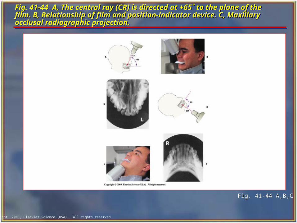
Fig. 41-44 A, The central ray (CR) is directed at +65˚ to the plane of the film. B, Relationship of film and position-indicator device. C, Maxillary occlusal radiographic projection.
Fig. 41-44 A, The central ray (CR) is directed at +65˚ to the plane of the film. B, Relationship of film and position-indicator device. C, Maxillary occlusal radiographic projection.
Fig. 41-44 A,B,CFig. 41-44 A,B,C
Copyright 2003, Elsevier Science (USA). All rights reserved.
Patients with Special Needs Patients with Special Needs Radiographic examination techniques must
often be modified to accommodate patients with special needs.
The dental radiographer must be competent in altering radiographic technique to meet the specific diagnostic need of the individual patient.
Radiographic examination techniques must often be modified to accommodate patients with special needs.
The dental radiographer must be competent in altering radiographic technique to meet the specific diagnostic need of the individual patient.

Copyright 2003, Elsevier Science (USA). All rights reserved.
Physical Disabilities Physical Disabilities A person with a physical disability may have
problems with vision, hearing, or mobility. You must make every effort to meet the
individual needs of such patients. In many cases, a family member or
caretaker accompanies the person with a physical disability to the dental office.
You can ask the caretaker to assist you with communicating concerning the physical needs of the patient.
A person with a physical disability may have problems with vision, hearing, or mobility.
You must make every effort to meet the individual needs of such patients.
In many cases, a family member or caretaker accompanies the person with a physical disability to the dental office.
You can ask the caretaker to assist you with communicating concerning the physical needs of the patient.
Copyright 2003, Elsevier Science (USA). All rights reserved.
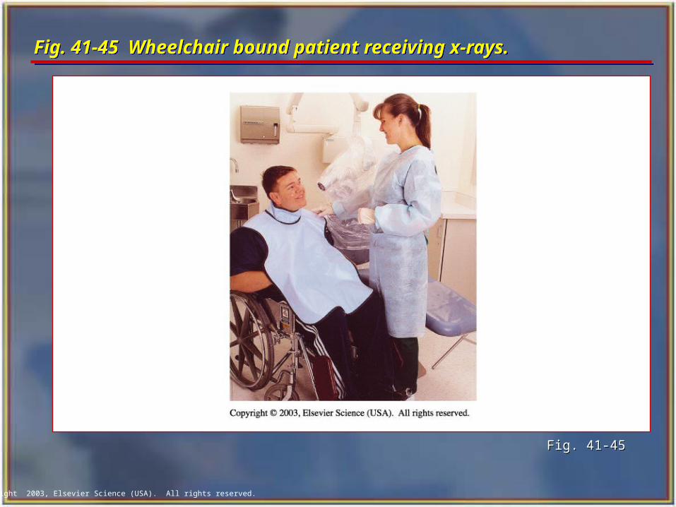
Fig. 41-45 Wheelchair bound patient receiving x-rays.Fig. 41-45 Wheelchair bound patient receiving x-rays.
Fig. 41-45Fig. 41-45
Copyright 2003, Elsevier Science (USA). All rights reserved.
Patients With Special Dental Needs Patients With Special Dental Needs
Reasons for radiographs on the edentulous patient:
• To detect the presence of root tips, impacted teeth, and lesions (cysts, tumors).
• To identify objects embedded in bone.
• To observe the quantity and quality of bone that is present.
Reasons for radiographs on the edentulous patient:
• To detect the presence of root tips, impacted teeth, and lesions (cysts, tumors).
• To identify objects embedded in bone.
• To observe the quantity and quality of bone that is present.
Copyright 2003, Elsevier Science (USA). All rights reserved.
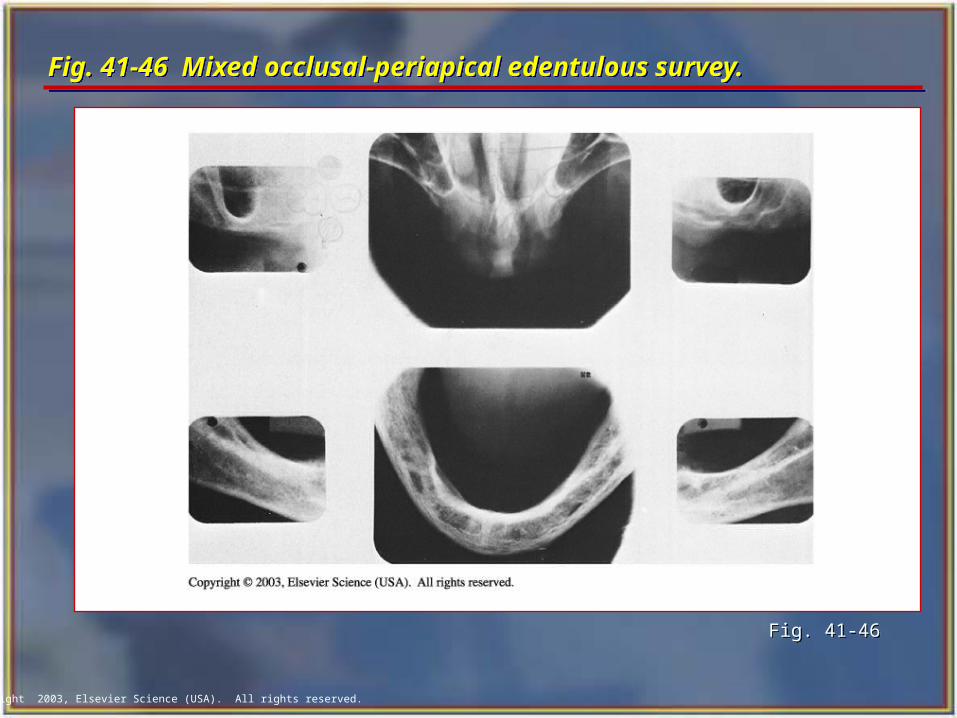
Exposure Techniques for the Edentulous PatientExposure Techniques for the Edentulous Patient The radiographic examination of an edentulous
patient may include a panoramic radiograph, periapical radiographs, or a combination of occlusal and periapical radiographs.
Radiographic images must be made in all teeth-bearing areas of the mouth whether or not teeth are present.
For edentulous patients, either the bisection of the angle or the paralleling technique may be used.
Because there are no teeth present, the distortion inherent in the bisecting technique does not interfere with the diagnostic intrabony conditions.
The radiographic examination of an edentulous patient may include a panoramic radiograph, periapical radiographs, or a combination of occlusal and periapical radiographs.
Radiographic images must be made in all teeth-bearing areas of the mouth whether or not teeth are present.
For edentulous patients, either the bisection of the angle or the paralleling technique may be used.
Because there are no teeth present, the distortion inherent in the bisecting technique does not interfere with the diagnostic intrabony conditions.
Copyright 2003, Elsevier Science (USA). All rights reserved.
Fig. 41-46 Mixed occlusal-periapical edentulous survey.Fig. 41-46 Mixed occlusal-periapical edentulous survey.
Fig. 41-46 Fig. 41-46
Copyright 2003, Elsevier Science (USA). All rights reserved.
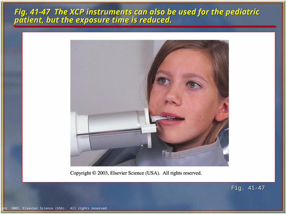
Radiographs for the Pediatric PatientRadiographs for the Pediatric Patient In children, radiographs are useful for detecting
conditions of the teeth and bones, for showing changes related to caries and trauma, and for evaluating growth and development.
Explain the radiographic procedures you are about to perform in terms that the child can easily understand. For example, you can refer to the tubehead as a camera, the lead apron as a coat and the radiograph as a picture.
Exposure factors (milliamperage, kilovoltage, time) must be reduced because of the smaller size of the pediatric patient.
In children, radiographs are useful for detecting conditions of the teeth and bones, for showing changes related to caries and trauma, and for evaluating growth and development.
Explain the radiographic procedures you are about to perform in terms that the child can easily understand. For example, you can refer to the tubehead as a camera, the lead apron as a coat and the radiograph as a picture.
Exposure factors (milliamperage, kilovoltage, time) must be reduced because of the smaller size of the pediatric patient.
Copyright 2003, Elsevier Science (USA). All rights reserved.
Fig. 41-47 The XCP instruments can also be used for the pediatric patient, but the exposure time is reduced.Fig. 41-47 The XCP instruments can also be used for the pediatric patient, but the exposure time is reduced.
Fig. 41-47Fig. 41-47
Copyright 2003, Elsevier Science (USA). All rights reserved.
The Patient Who Gags The Patient Who Gags To help prevent the gag reflex, you must convey a
confident attitude.
For the patient who has a hypersensitive gag reflex, you should expose the maxillary molars last.
When you place films in the maxillary posterior, do not slide them along the palate.
There may be times when you will encounter a patient with an uncontrollable gag reflex.
When this occurs, you must use extraoral radiographs such as panoramic or lateral jaw radiographs.
To help prevent the gag reflex, you must convey a confident attitude.
For the patient who has a hypersensitive gag reflex, you should expose the maxillary molars last.
When you place films in the maxillary posterior, do not slide them along the palate.
There may be times when you will encounter a patient with an uncontrollable gag reflex.
When this occurs, you must use extraoral radiographs such as panoramic or lateral jaw radiographs.
Copyright 2003, Elsevier Science (USA). All rights reserved.
Normal Anatomic LandmarksNormal Anatomic Landmarks To correctly mount dental radiographs,
the dental assistant must be able to recognize the normal anatomic landmarks on intraoral radiographs.
To correctly mount dental radiographs, the dental assistant must be able to recognize the normal anatomic landmarks on intraoral radiographs.
Copyright 2003, Elsevier Science (USA). All rights reserved.
Maxillary Anterior Landmarks Maxillary Anterior Landmarks Median palatine suture
Incisive foramen
Anterior nasal spine
Nasal septum
Nasal fossa
Median palatine suture
Incisive foramen
Anterior nasal spine
Nasal septum
Nasal fossa
Copyright 2003, Elsevier Science (USA). All rights reserved.
Landmarks of the MandibleLandmarks of the Mandible Genial tubercules Lingual foramen Nutrient canals Mental foramen Mandibular canal Coronoid process Mylohyoid ridge External oblique ridge Mental ridge
Genial tubercules Lingual foramen Nutrient canals Mental foramen Mandibular canal Coronoid process Mylohyoid ridge External oblique ridge Mental ridge
Copyright 2003, Elsevier Science (USA). All rights reserved.
Tips for Mounting RadiographsTips for Mounting Radiographs Handle films only by the edges. Label and date the film mount before
mounting the films. Include the patient’s full name and date of
exposure and the dentist’s name. Use clean and dry hands. Use a definite order for mounting films. Use the “smile” line to mount bite-wing
radiographs (BWXs).
Handle films only by the edges. Label and date the film mount before
mounting the films. Include the patient’s full name and date of
exposure and the dentist’s name. Use clean and dry hands. Use a definite order for mounting films. Use the “smile” line to mount bite-wing
radiographs (BWXs).
Copyright 2003, Elsevier Science (USA). All rights reserved.
Radiographs for the Endodontic PatientRadiographs for the Endodontic Patient
It often is difficult to obtain accurate radiographs during endodontic (root canal) treatment because of the rubber dam clamp, endodontic instruments, or filling material extending from the tooth.
The EndoRay II film holder can be used to aid in positioning the film during this portion of the root canal procedure.
This holder fits around a rubber dam clamp and allows space for endodontic instruments and filling materials to protrude from the tooth.