Embed Size (px)
Citation preview

77
CHAPTER 4
TESTING AND CORRELATION
4.1. INTRODUCTION
The testing of a machine both at the work and at site is very
important for a smooth operation of the machine. Tests are carried out
at the work to determine whether the machine has been
manufactured according to specifications of the customer and are in
conformity with the design of the electrical and mechanical designers.
Hence testing is essential at manufacturing works. This chapter,
therefore, describes preliminary tests that have to be performed before
assembling the machine in the test beds. Here, tests performed in the
test beds and the site tests i.e., tests on machines before
commissioning are also discussed.
4.2 OPEN CIRCUIT CHARACTERISTICS (MAGNETIZATION CURVE)
The fundamental electric properties of an alternator can be well
presented by its magnetization (no load) and short circuit
characteristics. All the parameters characterizing the operation of the
generator can be deduced from the above mentioned curves provided
stator winding leakage reactance is known. i.e, basic vector diagram of
the machine for every load may be constructed. The graphical
relationship which exists between the exciting current and the
terminal voltage of armature is called magnetization curve. It can be
obtained experimentally by taking various values of exciting current

78
and observing the corresponding armature voltages the machine being
operated on open circuit. Usually, it is necessary to insert a
considerable resistance in series with the field winding in addition to
the ordinary shunt regulator in order to bring down the exciting
currents so as to obtain points on the lower portion of the curve. The
resulting graph follows the general shape of the B-H curve.
4.2.1 OPEN CIRCUIT TEST on SRA:
1) Connections are made as per the circuit diagram as shown
in figure 4.1.
2) The M-G Set is brought to synchronous speed by varying DC
motor field.
3) By gradually varying the excitation, the corresponding open
circuit voltages are noted and tabulated as shown in table 4.1.
Graph is drawn between OC voltage and excitation as shown in
fig 4.2.

79
Fig 4.1: Circuit diagram for OCC test

80
Table 4.1 Observations of open circuit test
S.No. Field current
(If) in Amp.
Induced voltage
(V1) in Volts.
1 0 9
2 1.0 54
3 1.5 90
4 2.0 120
5 2.5 150
6 3.0 180
7 3.5 204
8 4.0 219
9 4.5 234
10 5.0 240
0 1 2 3 4 5 6
0
50
100
150
200
250
Field Current in Amp
Open
cir
cuit
vol
tage
in
Vol
ts
Fig. 4.2: open circuit characteristics

81
4.3 SHORT CIRCUIT CHARACTERISTICS
Under short circuit conditions the armature terminals of a
synchronous machine which is being driven by a prime mover at
synchronous speed are short circuited directly or through ammeter. It
has become a conventional that unless and until otherwise
mentioned, a short circuited synchronous machine is understood to
be a machine, where all the three terminals of which are short
circuited. The other short circuited conditions are those of two phase
and single phase short circuits as shown in figure , 4.3 , 4.4 and 4.5
respectively.
Fig.4.3: Three-phase short circuited synchronous machines
Fig.4.4: Two-phase short circuited synchronous machines

82
Fig.4.5: One-phase short circuited synchronous machines
A short circuit on a synchronous machine has the internal effect
as an inductive load since in comparison to the armature leakage
reactance, the armature resistance in almost all synchronous
machines has a negligible value. The armature mmf acts directly
opposed to the field mmf in such a case. The resultant ampere-turns
inducing the armature emf are, therefore the numerical difference
between the field and armature mmfs. Since the terminals of the
machine are short circuited, the emf induced in the armature winding
by the resultant ampere-turns is equal to the voltage drop in the
winding itself. If Me, Ma be the field and armature mmf’s, the
difference Me-Ma, representing the resultant mmf Mr, induces an emf
in the armature winding. This induced voltage balances the
impedance drop IZa in the armature winding. The occ and scc
characteristics are shown in figure 4.6
In a short circuited synchronous machine the field current is
gradually increased, the current flowing in the armature winding

increases proportionally. From the results so recorded, data to
determine short circuit ratio (SCR) could be obtained.
Fig.4.6: OCC and SCC characteristics
4.3.1. SHORT CIRCUIT TEST on SRA:
1) Connections are made as per requirement as shown in fig
2) The M-G Set is brought to synchronous speed.
3) A three phase short circuit is applied to the output of the alternator
through contactor.
4) By varying the field excitation the corresponding short circuit
current readings are noted and tabulated in table 4.2.
5) A graph is drawn between short circuit current and excitation
current as shown in Fig. 4.8.
83
ionally. From the results so recorded, data to
determine short circuit ratio (SCR) could be obtained.
Fig.4.6: OCC and SCC characteristics
SHORT CIRCUIT TEST on SRA:
Connections are made as per requirement as shown in fig
G Set is brought to synchronous speed.
3) A three phase short circuit is applied to the output of the alternator
through contactor.
4) By varying the field excitation the corresponding short circuit
current readings are noted and tabulated in table 4.2.
5) A graph is drawn between short circuit current and excitation
current as shown in Fig. 4.8.
ionally. From the results so recorded, data to
Connections are made as per requirement as shown in fig 4.7.
3) A three phase short circuit is applied to the output of the alternator
4) By varying the field excitation the corresponding short circuit
5) A graph is drawn between short circuit current and excitation

84
Fig.4.7: Circuit diagram for short circuit test

85
Table 4.2: observations of short circuit test
S.No. Field current
(If) in Amp.
Short Circuit
current (Isc) in
A mp.
1 0 0
2 1.0 1.4
3 1.5 2.3
4 2.0 3.0
5 2.5 3.8
6 3.0 4.5
7 3.5 5.4
8 4.0 6.0
9 4.5 6.6
10 5.0 7.5
0 1 2 3 4 5 6
0
1
2
3
4
5
6
7
8
Field current in Amp
Sh
ort
circu
it c
urr
en
t in
Am
p
Fig. 4.8: SC characteristics
4.4 SHORT CIRCUIT RATIO:
The short circuit ratio of a synchronous machine is defined as
the ratio of the field current required to produce rated voltage at rated

86
speed and no load to the field current required to produce rated
armature current under a sustained three phase short circuit.
If there were no saturation, the short circuit ratio would be
equal to the reciprocal of the synchronous reactance. Saturation has
the effect of increasing the short circuit ratio .The short circuit ratio
has significance with respect to both the performance of the machine
and its cost. The lower the short circuit ratio, the greater is the change
in field current required to maintain constant terminal voltage for a
given change in load and lower is the steady state limit.
If there is no saturation the short circuit ratio would be
constant at all voltage or to be exact at all excitation currents or fields.
Hence the maximum power available in steady state is directly
proportional to the short circuit ratio and can be increased by
increasing the short circuit ratio .The short circuit ratio can be
increased by increasing the air gap of the machine.
An increase in air gap would mean a bigger model and hence
contain more material. The electrical and magnetic parts of the
machine need more copper and iron respectively and hence the cost of
the machine increases. An increase in short circuit ratio further
results in increase in the steady state or sustained short circuit
current and hence the designer has to find a compromise. The
maximum power in steady state condition is also dependent upon
excitation, therefore as a result of improvements in excitation systems

87
there has been a trend towards the use of lower short circuit ratio and
consequently lower cost.
Steam turbine driven generator i.e. turbo alternator are built
with S.C.R anywhere in the range from 0.5 to 1.1 .Most modern
generator of this type have a ratios range from 0.8 to 1.1but it
appears that 0.7 is more likely used. Water wheel generators have
been designed with short circuit ratio up to 2.How ever modern water-
wheel generators are universally designed with S.C.R from 0.9 to
1.10.Synchronous condensers have the value of S.C.R as low as 0.5.
4.4.1 Short circuit ratio of SRA
The field current required to produce an induced emf equal to
rated voltage of 230V is 4.3A ( as derived from the Fig. 4.2).
The field current required to circulate a short circuit current
equal to rated current of 7A is 4.7A (as derived from the Fig.4.8).
SCR of SRA = 4.3/4.7 = 0.91
As this designed SRA is of low rating, it does not fall into
saturation while it is shorted. Hence synchronous reactance (Xs) of
this SRA is reciprocal of SCR.
Xs = 1/ (0.91) = 1.098

88
4.5. HEAT RUN TEST ON SRA
Heat run test of a synchronous machine determines the
temperature rise which is measured by using IR THERMOMETER as
shown in figure 4.10. This of the various parts of the machine under
rated load conditions. Depending on the class of insulation used the
temperature in any part of the machine should not increase beyond
permissible limits. In the case of large machines, it is not possible to
load them for rated conditions for test bed, as loading in such cases
requires large prime movers and loading capacities.
Generally, in test beds the full load heat run test is split into
two heat run tests namely the open circuit and short Circuit heat run
tests. The final temperature rise on full load is then determined by a
superimposition of the two heat run tests. It is inferred that the
temperature rise follows very nearly an exponential function and that
the thermal-time-constant of synchronous machines vary between 60
to 240 minutes. The temperature rise in the field winding can be
watched continuously by measuring the resistance of the winding by
recording the voltage and current in the field winding. The core
temperature should in no way be above 100°C as under such
conditions the teeth which have much higher flux densities are
definitely about 20°C higher than the core.
The resistance is measured by using the micro ohmmeter
shown in figure 4.9. All the observations are tabulated in table 4.3
89
and the measured cold resistance and heat resistance are tabulated in
table 4.4.
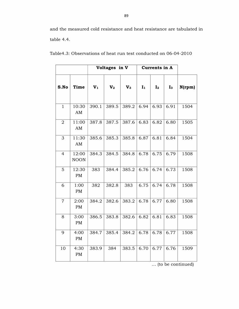
Table4.3: Observations of heat run test conducted on 06-04-2010
Voltages in V Currents in A
S.No
Time
V1
V2
V3
I1
I2
I3
N(rpm)
1 10:30 AM
390.1 389.5 389.2 6.94 6.93 6.91 1504
2 11:00 AM
387.8 387.5 387.6 6.83 6.82 6.80 1505
3 11:30 AM
385.6 385.3 385.8 6.87 6.81 6.84 1504
4 12:00 NOON
384.3 384.5 384.8 6.78 6.75 6.79 1508
5 12:30 PM
383 384.4 385.2 6.76 6.74 6.73 1508
6 1:00 PM
382 382.8 383 6.75 6.74 6.78 1508
7 2:00 PM
384.2 382.6 383.2 6.78 6.77 6.80 1508
8 3:00 PM
386.5 383.8 382.6 6.82 6.81 6.83 1508
9 4:00 PM
384.7 385.4 384.2 6.78 6.78 6.77 1508
10 4:30 PM
383.9 384 383.5 6.70 6.77 6.76 1509
… (to be continued)

90
Table 4.3: Observations of heat run test
… (to be continued)
Armature Field
S.No
Time
D.C
(Iarm)
D.C
(Varm)
D.C
(If)
D.C
(Vf)
Power
meter
(Kw)
1 10:30 AM
3.1 198 3.59 141 4.64
2 11:00 AM
3.0 202 3.72 152 4.57
3 11:30 AM
3.0 202 3.68 151 4.54
4 12:00 PM
2.9 200 3.71 152 4.48
5 12:30 NOON
2.9 201 3.71 153 4.46
6 1:00 PM
2.9 207 3.71 144 4.49
7 2:00 PM
2.9 197 3.71 134 4.49
8 3:00 PM
3.0 195 3.71 134 4.49
9 4:00 PM
3.0 193 3.71 134 4.49
10 4:30 PM
3.0 191 3.71 134 4.45

91
Table 4.3: Observations of heat run test
Temperatures in degree centigrade
S.No
Time
Room
Body
Driving
end
Non-
driving
end
1 10:30 AM
34.4 34.4 -- 37
2 11:00 AM
34.9 47.2 -- 39
3 11:30 AM
34.9 51.1 38 41
4 12:00 AM
34.9 55.3 40 42
5 12:30 NOON
34.9 56 42 44
6 1:00 PM
36.3 61 43 44
7 2:00 PM
36.9 64 45 45
8 3:00 PM
36.9 65 45 45
9 4:00 PM
36.9 66 46 46
10 4:30PM 37.7 66 46.5 46.5

92
Fig.4.9: Resistance is measured by Micro ohm meter LR-2045
Fig.4.10: Temperature measured by
FLUKE IR THERMOMETER

93
Table 4.4: Cold resistance and heat resistance
Beginning ( 10 : 30 AM) Ending ( 4 : 30 PM)
Line Resistance Line Resistance
RY = 96.6mΩ YB = 96.9.mΩ BR = 96.4mΩ
RY = 105.3mΩ YB = 105.4mΩ BR = 105.1mΩ
Phase resistances Phase resistances
RN = 47.6mΩ YN = 47.9mΩ
BN = 47.7mΩ .
RN = 51.7mΩ YN = 51.1mΩ BN = 51.4mΩ
Field Resistance Field Resistance
0.017 kΩ
0.018 kΩ
It is inferred from the table 4.3 that the thermal time constant of this
SRA is approximately 90 minutes.
4.6. LOAD CHARACTERISTICS:
The load characteristic of an alternator is obtained by
determining the relationship between the terminal voltage and the
load current, while the exciting current and the speed is kept
constant.
As the armature current is increased, the terminal voltage drops
due to many reasons, but when The power factor is leading the load
characteristic curve may raise at first. Each curve is nearly straight at
the beginning but tends to droop because, with the increase in load

94
current, the angle of lag between current and emf, owing to the
original field increases.
In modern alternators the steady short circuit current is not
much greater than full load rated current .This is purposely arranged
to prevent excessive current in the event of short circuit.
4.6.1 Load Test on SRA:
In order to obtain the relation between terminal voltage and load
current and also to determine the efficiency, load test [25] is
conducted.
The MG set is made to run at synchronous speed, the resistive
load bank is gradually applied on the machine and the corresponding
readings are tabulated as shown in the table 4.5 and graph is drawn
as shown in Fig. 4.11.

95
Table 4.5: Observations of load test
Power
meter
readings
In Kw
Terminal
voltage
(VL) in V
Load
Current
(IL) in A
Field
Current
(If) in A
0.8 392 1.2 3.8
1.22 392 1.8 3.8
1.6 385 2.4 3.8
1.8 384 2.8 3.8
2.18 382 3.3 3.8
2.4 382 3.7 3.8
2.82 378 4.3 3.8
3.2 378 4.9 3.8
3.5 378 5.4 3.8
3.7 376 5.8 3.8
4.2 375 6.6 3.8
4.6 374 7.2 3.8

96
0 1 2 3 4 5 6 7 8
0
50
100
150
200
250
300
350
400
Ter
min
al V
olta
ge in
Vol
ts
Load current in Amp
Fig. 4.11: Load characteristics
4.6.2 Efficiency
The input of the alternator is the mechanical torque of the D.C
motor which is measured by the TORQUE SENSOR as shown in figure
4.12. and its corresponding block diagram is shown in
figure 4.13
Fig.4.12 Torque Sensor

97
Fig. 4.13 Block diagram to find torque
Efficiency of the SRA = Output of SRA/ Input of SRA
Output of SRA is nothing but electrical power =
3 cos
3 378 5.4 1
3535.46
out l l
out
P VI
P W
φ= ×
= × × ×
=
Input to SRA is nothing but output of DC motor which is mechanical
power
Generally power is defined as torque (T) × angular velocity (ω )=
2
60
2 150026.275
60
4127.25
in
in
in
NP T
P
P W
π
π
= ×
× = ×
=
Shaft torque 26.275 is read by torque sensor
Efficiency of the SRA is
D.C MOTOR
TORQUE
SENSOR
S.R.A

98
3535.46
100 1004127.25
85.66%
out
in
P
Pη
η
= × = ×
=
Taking the efficiency of the prime mover i.e., DC motor as 86.5%
Efficiency of the MG-set = Efficiency of DC motor × Efficiency of SRA
= 0.865×0.8566 =0.7409
=74.09%
4.7 CONCEPT OF BALANCED AND UNBALANCED LOAD
CONDITIONS
A synchronous machine operating under balanced and
unbalanced conditions can be analyzed on the basis of two basic
concepts viz. The method of symmetrical components and Blondel’s
two reaction theory.
The set of three equal stator currents which produce a flux wave
rotating at synchronous speed with the rotor forms positive phase
sequence currents and they are designated as Ia1,Ib1 and Ic1.
The set of three equal stator currents which produce a flux wave
rotating at synchronous speed against the rotor forms negative phase
sequence currents and they are designated as Ia2,Ic2 and Ib2.
The set of three equal stator currents which produce no net
fundamental air gap flux (because the three currents are in time
phase under displaced by 120 elec degrees apart) identified as zero
sequence currents and they are designated as Ia0,Ib0 and Ic0.

99
Positive, negative and zero sequence currents may exist not only
as fundamental frequency currents but also as harmonics. For
example, under balanced conditions all triple harmonic currents are
zero sequence.
Blondel’s two reaction theory deals mainly with positive
sequence currents [26]. Unbalanced loading of a generator effects
heating of solid iron and damping circuits which is due to rotor
currents induced at twice the supply frequency. This abnormal
heating of solid iron limits the negative sequence capability of machine
[27].
The additional losses due to negative phase sequence stator
currents will exist on the surface of the rotor for solid rotor turbo
generators [28]. The study of unbalanced currents reveals significance
of rotor design features and practices.
4.7.1 BALANCED LOAD TEST
In order to observe the variations in the voltage and currents
while the SRA is subjected to phase loading, balanced load test is
conducted.
Rheostat load has been connected to the SRA and the load
setting across each branch is done by selector switches. The
corresponding readings captured by power meter are tabulated in
table 4.6 and 0ne of the reading is shown in the fig: 4.14.

100
Table 4.6: Observations of balanced load test
Fig: 4.14 power meter reading depicting balanced loads
DC MOTOR
SIDE
ALTERNATOR SIDE
S.No
Input
voltage
Input
current
V1
V2
V3
I1
I2
I3
Power
(kW)
1
195.2
2.12
102.5
102.0
103.0
0.56
0.56
0.56
0.17
2
193.2
2.52
180.1
180.3
180.1
4.3
4.3
4.3
2.32
3
192.7
2.95
232.2
231.1
232.2
5.9
5.9
5.9
4.11
101
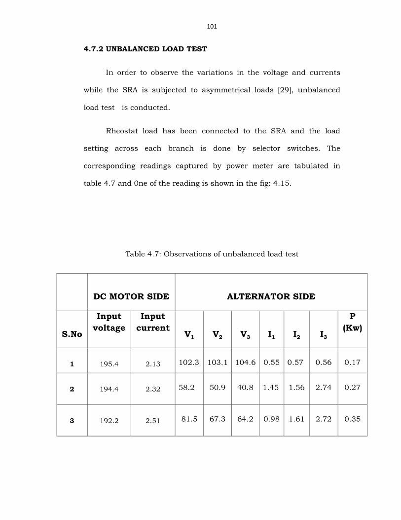
4.7.2 UNBALANCED LOAD TEST
In order to observe the variations in the voltage and currents
while the SRA is subjected to asymmetrical loads [29], unbalanced
load test is conducted.
Rheostat load has been connected to the SRA and the load
setting across each branch is done by selector switches. The
corresponding readings captured by power meter are tabulated in
table 4.7 and 0ne of the reading is shown in the fig: 4.15.
Table 4.7: Observations of unbalanced load test
DC MOTOR SIDE
ALTERNATOR SIDE
S.No
Input
voltage
Input
current
V1
V2
V3
I1
I2
I3
P
(Kw)
1
195.4
2.13
102.3
103.1
104.6
0.55
0.57
0.56
0.17
2
194.4
2.32
58.2
50.9
40.8
1.45
1.56
2.74
0.27
3
192.2
2.51
81.5
67.3
64.2
0.98
1.61
2.72
0.35

102
Fig.4.15: Readings captured by power meter CW-140
The inverse currents [30] caused by unbalanced load in the
rotor pulsate with twice the grid frequency. Therefore, the associated
eddy currents in the solid rotor iron flow in a thin layer under the iron
surface specified by the penetration depth. Besides the skin effect
forcing them to flow in a thin layer under the iron surfaces the eddy
currents are subjected to a second skin effect. It becomes obvious
when encircling both the currents in the damper and the slot walls.
Together they built up a resultant ampere turn value which drives a
common leakage flux across the slot. It is well known that the damper
is subjected to a skin effect that displaces this currents towards the
slot openings. Without any additional reasoning it can be stated that
the same applies to the eddy currents in the slot walls. Thus, the
currents in the iron are not only limited by the impedances built up by
the iron but also by the common leakage reactance attributed to the
damper and iron currents.

103
The additional losses of the SRA due to negative sequence
currents [31] is calculated based on the readings recorded in the
above table 4.6 & 4.7. In other words, the additional losses [32] due to
negative sequence currents is nothing but the difference in power
input to the DC motor while the MG set subjected to both the
balanced and unbalanced loads.
The input power drawn by the DC motor while the MG set is
connected to the balanced load = 195.2*2.12
= 413.824 W
The input power drawn by the DC motor while the MG set is
connected to unbalanced load = 195.4*2.13
= 416.202 W
Additional loss of the SRA is nothing but the difference of above two
inputs
i.e., 416.202 - 413.824 = 2.378 W
∴ Additional losses due to Negative-seq. currents = 2.378 W
Total losses of SRA =output – input
= 3876.14-3320.3
= 555.84W
The percentage of additional losses = 2.378/555.8 = 0.43%
104
As this designed SRA is of low rating and the wedges are made of
Glass laminates, the additional losses due to negative sequence
currents are very small. In large machines the wedges are metallic and
the rotor is made of solid iron forging. Hence the negative sequence
capability is limited to 10 % in order to limit negative sequence losses
and rotor heating.
4.8 THREE PHASE SHORT CIRCUIT FAULT ON A
SYNCHRONOUS GENERATOR:
A sudden short circuit [34] in a synchronous machine takes place
if the machine is running at synchronous speed and having been
excited is suddenly short circuited on its terminals. This may take
place either when the machine is running on no-load or when it is
loaded. The loading may either be direct-loading at the terminals of
the machine or the machine may be synchronized to a grid supplying
power to the grid therewith. Modern synchronous machines are star-
connected. Synchronous machines with isolated neutrals and as such
conditions of a 3-phase or a 2-phase sudden short-circuit are the only
ones, which are of importance from a practical point of view. As a
result of sudden short-circuits, large currents flow in the machines.
Knowledge of these currents is essential in order to design the support
of the winding-head and the foundation of the machines.
In no-load operation of the synchronous machine, the total flux
linking the rotor windings consists of the useful flux Φ and field
leakage flux Фel.

105
. .po cΦ = elΦ+Φ
In steady state 3-phase short circuit operation of the machine, the
total flux linking the rotor windings consists of the effective useful flux
effΦ and the field leakage flux.
. .ps cΦ = eff el
Φ +Φ
The effective useful flux depends upon the effective field current
and can be determined with the help of the equivalent circuit diagram
of the synchronous machine in three-phase steady state short-circuit
condition. Since both the field and the armature reaction m.m.f have
their axes in the direct-axis, only the direct-axis equivalent circuit
diagram is considered. Since the steady state 3-phase short-circuit
corresponds to a purely inductive loading, the effect of the field
current is partly neutralized by the armature reaction. For a given
field current the induced e.m.f in the armature is .e adi x
The armature current I = al ad
E
x x+ =
.e ad
al ad
i x
x x+
Hence the effective field current = ei I− = .
e ad
e
al ad
i xi
x x−
+
. al
eeff e
d
xi i
x=
Therefore

106
. al
eff
d
x
xΦ = Φ
and hence
. . . al
ps c el
d
x
xΦ = Φ + Φ
The total flux linking the rotor under short-circuit conditions . .ps cΦ is
smaller than . .po cΦ which is the total flux linking the rotor under open-
circuit conditions. In case a three-phase sudden short-circuit occurs
on the terminals of an unloaded synchronous machine, the flux . .po cΦ
cannot suddenly change its value to . .ps cΦ due to the magnetic inertia.
The only difference between a sudden and a steady state short-circuit
is called for by the transients which come into play because of
magnetic inertia. Due to magnetic inertia, not only the rotor links total
flux but also the flux values linked with the three stator phases at the
instant of the sudden short circuit, have tendencies to retain their
values.
It is needless to say that a sudden short-circuits of the three
terminals of an excited synchronous machine causes large short-
circuit currents to flow in the armature of the synchronous machine.
These sudden short-circuit currents decay down to the steady state
value within a few seconds. The sudden short-circuit test is carried
out in order to determine the various constants mentioned and also to

107
see whether the machine is capable to withstand the mechanical
stresses developed by the sudden short circuit currents.
Before performing the test the machine should be carefully
inspected to see that the bracing of the stator coil ends is satisfactory
and that the foundation is in good condition and the holding down
bolts are tight. The rotor should also be inspected to see that all keys
and bolts are in place and properly tightened. Generally oscilloscope
readings are taken to determine reactances. It is, therefore, necessary
to short-circuit the machine by a circuit-breaker which closes all three
circuits at almost exactly the same instant to avoid errors due to
single phase action at the beginning of the short-circuit. Precision
shunts are used for recording the currents on an oscilloscope. It must
not be forgotten that the shunts have to be earthed.
The major effects of short circuit are increase in armature
current which in term result in large electro dynamic forces. These
forces may either be between the winding head and iron are the
between the winding heads are different phases. The large electro
dynamo forces can result in a displacement of the end portions of the
stator coils against one another. These displacements can result in an
injury to the insulation of the winding and hence shut down of the
machine. The end portions of the coils must, therefore, be specially
braced. Besides the forces in the end portions of the coils, sudden
short circuits by a synchronous machine result in torque pulsation.

108
As a result of these torques of high magnitude the casing, the
shaft and the foundation must be designed to withstand the stresses.
The very high values of armature currents cause I2R losses in
the machine which in turn result increased heating of the machine.
since the sudden short circuits are switched off with in a very
short time, the heating in the machines due to them is generally not
appreciable.

4.8.1 Three phase Short circuit Fault on SRA:
Fig 4.16: Experimental setup for 3
After assimilating the procedure of a three phase short circuit and its
effects as mentioned in the section 4.8, a t
experiment is performed on the SRA as shown in Fig.4.16
corresponding circuit diagram in
109
Three phase Short circuit Fault on SRA:
TRANSIENT RECORDER
Experimental setup for 3-phase short circuit fault
After assimilating the procedure of a three phase short circuit and its
effects as mentioned in the section 4.8, a three phase short circuit
experiment is performed on the SRA as shown in Fig.4.16
corresponding circuit diagram in Fig. 4.17
TRANSIENT RECORDER
phase short circuit fault
After assimilating the procedure of a three phase short circuit and its
hree phase short circuit
experiment is performed on the SRA as shown in Fig.4.16 and the
110
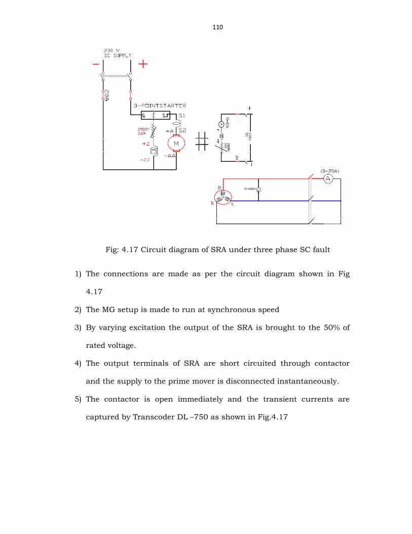
Fig: 4.17 Circuit diagram of SRA under three phase SC fault
1) The connections are made as per the circuit diagram shown in Fig
4.17
2) The MG setup is made to run at synchronous speed
3) By varying excitation the output of the SRA is brought to the 50% of
rated voltage.
4) The output terminals of SRA are short circuited through contactor
and the supply to the prime mover is disconnected instantaneously.
5) The contactor is open immediately and the transient currents are
captured by Transcoder DL –750 as shown in Fig.4.17

111
Fig. 4.18 Voltage and current of SRA during 3phase short circuit
As the damper windings are absent in the designed SRA and the
height of wedges has been machined during redesigning process. The
sub transient current is not noticeable which is evident from figure
4.18.
The behavior of the voltage before, during and after short
circuit can be well understood from Fig. 4.19.

112
Fig 4.19 Voltage: Before, during and after three phase SC fault
Fig 4.20 The currents in all three phases during three phase SHORT CIRCUIT
As the three phase short circuit is a symmetrical fault, the
currents in all the three phases will be equal in magnitude which is
depicted in Fig. 4.20.

113
4.8.2 Determination of Reactances from 3phase sudden short
circuit test
The direct-axis sub-transient and transient reactances are
determined from the current waves of a three-phase short-circuit
suddenly applied to the machine operating at no-load and rated
speed.The current peaks in one of the three phases are plotted on a
graph paper. In plotting the current values from the oscillogram, the
first peak should be plotted at abscissa 1 and subsequent peaks
numbered consequently. The positive peaks are therefore given odd
numbers and the negative even numbers.
The current values from the oscillograms should be plotted
first and then the median line and the a.c. component. The curves are
usually plotted on standard rectangular co-ordinates and most
conveniently analyzed if the currents are expressed in p.u. values,
with the unit value equal to the peak value of the rated current wave.
The a.c. component of the current is then replotted on the semi-
log scales with the current on the logarithmic scale. Since the first
peak is plotted at abscissa 1, the abscissa for the time of application
of the short-circuit is usually not at zero, but at a time which can be
readily determined from the oscillogram. The zero time line should be
drawn on the semi-log plot and extrapolations of the current curves
are extended to this line. Since the plot of the current on a semi-log
paper is represented by a straight line together with a curve of several

114
cycles at the beginning of the short-circuit, it is important to choose
such time and current scales that will avoid a steep slope during the
first three or four cycles.
The straight line in the current-time plot on a semi-log paper is
extrapolated to zero time and
dX ' = dI
E
'
Where
E = the open circuit voltage of the machine immediately before
the sudden short-circuit expressed in p.u
dI' = per unit current from the current in the transient state
dX" = dI
E
"
dI" is the per unit current from the a.c. component curve at t=0
and E has already been defined.
NOTE: It is not essential that the sudden short-circuit should be
performed to determine the values of dX" , dX ' . The method for the
determination of dX" in standstill has already been described. The
difficulty, however, arises in the determination of dX ' . The modern
practice is to determine dX" and dX ' with the help of suddenly

115
switching off the three-phase sustained short-circuit. A record of the
recovery voltage with time helps us to determine dX" and dX ' .
The following machine parameters [35] have been determined from the
Fig4.17 and 4.19.
Base KVA = 5
Base KVLL =O.400
Base Current,A = 5/(√3 * 0.400) = 6.95
Base Impedance = (Base KVLL )2* 1000/ Base KVA
= 32 Ω
Actual Impedance(Za) = Rated Voltage/Rated current
= 400/(√3 * 7.5) =30.33
Per unit Impedance =[(Za)* (KVA)B]/[ (KV)2B * 1000]
= (30.33 * 5 )/ [(0.415)*1000]
= 0.881
Sub-transient Current(Id′′) = 10 p.u
Sub-transient Reactance( Xd′′) =1.0/10= 0.1
Transient Current( Id′) = 4.5 p.u
Transient Reactance( Xd′) = 1/4.5 = 0.22
Steady state Current(Id) =0.9 p.u
116
Steady state reactance(Xd) = 1/0.9 = 1.1
Sub transient reactance, Xd″ = 0.1
Transient Reactance, Xd′ = 0.22
Steady state reactance Xd = 1.1
4.9 L – L FAULT ON SYNCHRONOUS GENERATOR
An experiment to illustrate a three phase L-L fault is performed on
the SRA as shown in Fig.4.21.
1. The MG setup is made to run at synchronous speed.
2. By varying excitation the output of the SRA is brought to the 50% of
rated voltage.
3. The two phases of output terminals of SRA are short circuited
through contactor and the supply to the prime mover is
disconnected instantaneously [36].
4. The contactor is opened immediately and the transient voltages and
currents are captured by Transcoder DL-750 as shown in
Fig.4.22and its enlarged form is shown in Fig.4.23

117
Fig 4.21 Circuit diagram for LL- Fault Experiment
Fig 4.22 Voltage and current at the instant of LL-fault

118
Fig 4.23 Enlarged wave form of V and I during L-L fault
4.9.1 Determination of Reactances from L-L fault on SRA
The direct-axis sub-transient and transient reactances are
determined from the current waves of a L-L fault suddenly applied to
the machine operating at no-load and rated speed. The procedure to
calculate the various reactances for L-L fault condition is same as
mentioned in section 4.8.2. The machine parameters for L-L fault
condition [37] have been determined from the Fig 4.22 & Fig 4.23
Sub-transient Current(Id″) = 6.4 p.u
Sub-transient Reactance( Xd″) =1.0/6.4= 0.156
Transient Current( Id′) = 4.2 p.u
Transient Reactance( Xd′) = 1/4.2 = 0.238
Steady state Current(Id) = 0.8 p.u

119
Steady state reactance(Xd) = 1/0.8 = 1.25
Sub transient reactance, Xd″ = 0.156
Transient Reactance, Xd′ = 0.238
Steady state reactance Xd = 1.25
4.10 CONCLUSIONS
1. The short circuit ratio of SRA is calculated from OC and SC
tests and found as 0.91.
2. The synchronous reactance of SRA is determined as 1.098.
3. The percentage change in resistance for a rise in temperature of
32°C is found as 10% approximately.
4. The thermal time constant of SRA is observed as 90min
5. The value of efficiency of SRA is calculated as 85.66%
6. The additional losses of the SRA due to negative sequence
currents is found 2.378W which is 0.43% of total losses
7. The machine reactances for three phase short circuit and L-L
fault are calculated from the respective graphs.
CHAPTER 5
HARMONIC COMPENSATION