Embed Size (px)
Citation preview
51
Chapter 4
STRUCTURAL DESIGN CRITERIA
4.1 GENERAL
4.1.1 Scope. The structural design criteria to be used in the design of buildings and other structures and their components shall be as prescribed in this chapter. As an alternative, the seismic analysis and design procedures of Alternative Simplified Chapter 4 shall be permitted to be used in lieu of the requirements of this chapter, subject to all of the limitations contained in the Alternate Chapter 4.
4.1.2 References. The following reference documents shall be used as indicated in this chapter.
ACI 318 Building Code Requirements for Structural Concrete, American Concrete Institute, 1999, excluding Appendix A.
AISC ASD Allowable Stress Design and Plastic Design Specification for Structural Steel Buildings, American Institute of Steel Construction, 1989.
AISC LRFD Load and Resistance Factor Design Specification for Structural Steel Buildings, American Institute of Steel Construction, 1993.
AISC Seismic Seismic Provisions for Structural Steel Buildings, Part I, American Institute of Steel Construction, 1997, including Supplement No. 2 (2000).
AISI Specification for the Design of Cold-formed Steel Structural Members, American Iron and Steel Institute, 1996, including Supplement No. 1 (2000).
ASCE 7 Minimum Design Loads for Buildings and Other Structures, American Society of Civil Engineers, 1998.
4.1.3 Definitions
Base: The level at which the horizontal seismic ground motions are considered to be imparted to the structure.
Base shear: Total design lateral force at the base.
Bearing wall: An exterior or interior wall providing support for vertical loads.
Bearing wall system: A structural system with bearing walls providing support for all or major portions of the vertical loads. Shear walls or braced frames provide seismic-force resistance.
Braced frame: An essentially vertical truss that is provided to resist the effects of horizontal loads.
Building: Any structure whose use could include shelter of human occupants.
Building frame system: A structural system with an essentially complete space frame system providing support for vertical loads. Seismic-force resistance is provided by shear walls or braced frames.
Cantilevered column system: A seismic-force-resisting system in which lateral forces are resisted entirely by columns acting as cantilevers from the foundation.
Collector: See drag strut.
Component: See Sec. 1.1.4.
2003 Provisions, Chapter 4
52
Concentrically braced frame (CBF): A braced frame in which the members are subjected primarily to axial forces.
Dead load: The gravity load due to the weight of all permanent structural and nonstructural components such as walls, floors, roofs, and the operating weight of fixed service equipment.
Design strength: Nominal strength multiplied by the strength reduction factor, φ.
Diaphragm: A roof, floor, or other membrane system acting to transfer lateral forces to the vertical resisting elements. Diaphragms are classified as either flexible or rigid according to the requirements of Sec. 4.3.2.1 and 12.4.1.1.
Drag strut: A diaphragm or shear wall boundary element parallel to the applied load that collects and transfers diaphragm shear forces to the vertical force-resisting elements or distributes forces within the diaphragm or shear wall.
Dual frame system: A structural system with an essentially complete space frame system providing support for vertical loads. Seismic force resistance is provided by a moment resisting frame and shear walls or braced frames as prescribed in Sec. 4.3.1.1
Eccentrically braced frame (EBF): A braced frame in which at least one end of each diagonal connects to a beam a short distance from a beam-column joint or from another diagonal.
Height: Distance measured from the base of the structure as defined in sec. 4.1.3 to the roof level.
Intermediate moment frame: A moment frame of reinforced concrete satisfying the detailing requirements of ACI 318, of structural steel satisfying the detailing requirements of AISC Seismic, or of composite construction satisfying the requirements of AISC Seismic.
Inverted pendulum-type structure: Structures that have a large portion of their mass concentrated near the top and, thus, have essentially one degree of freedom in horizontal translation. The structures are usually T-shaped with a single column supporting the beams or framing at the top.
Joint: See Sec. 9.1.3.
Live load: The load superimposed by the use and/or occupancy of the structure not including the wind load, earthquake load, or dead load.
Moment frame: A frame provided with restrained connections between the beams and columns to permit the frame to resist lateral forces through the flexural rigidity and strength of its members.
Nominal strength: Strength of a member or cross section calculated in accordance with the requirements and assumptions of the strength design methods of these Provisions (or the reference standards) before application of any strength reduction factors.
Ordinary concentrically braced frame (OCBF): A steel concentrically braced frame in which members and connections are designed in accordance with the provisions of Ref. 8-3 without modification.
Ordinary moment frame: A moment frame of reinforced concrete conforming to the requirements of ACI 318 exclusive of Chapter 21, of structural steel satisfying the detailing requirements of AISC Seismic, or of composite construction satisfying the requirements of AISC Seismic.
Plain concrete: See Sec. 9.1.3.
Reinforced concrete: See Sec. 9.1.3.
Required strength: Strength of a member, cross section, or connection required to resist factored loads or related internal moments and forces in such combinations as stipulated by these Provisions.
Seismic Design Category: See Sec. 1.1.4.
Seismic-force-resisting system: See Sec. 1.1.4.
Structural Design Criteria
53
Seismic forces: See Sec. 1.1.4.
Seismic Use Group: See Sec. 1.1.4.
Shear panel: A floor, roof, or wall component sheathed to act as a shear wall or diaphragm.
Shear wall: A wall designed to resist lateral forces parallel to the plane of the wall.
Space frame system: A structural system composed of interconnected members, other than bearing walls, that is capable of supporting vertical loads and that also may provide resistance to shear.
Special concentrically braced frame (SCBF): A steel or composite steel and concrete concentrically braced frame in which members and connections are designed for ductile behavior
Special moment frame: A moment frame of reinforced concrete satisfying the detailing requirements of ACI 318, of structural steel satisfying the detailing requirements of AISC Seismic, of composite construction satisfying the requirements of AISC Seismic, or of masonry construction satisfying the requirements of Sec. 11.7. Special Shear plate steel wall: A shear wall composed of steel webs and structural steel boundary elements.
Story: The portion of a structure between the tops of two successive finished floor surfaces or, for the topmost story, between the finished floor surface and the top of the roof structural element.
Story drift ratio: The story drift, as determined in Sec. 5.2.6, 5.3.5, or 5.4.3, divided by the story height.
Structure: See Sec. 1.1.4.
Subdiaphragm: A portion of a diaphragm used to transfer wall anchorage forces to the diaphragm cross ties.
Wall: A component that is used to enclose or divide space and is inclined at an angle of at least 60 degrees from the horizontal plane.
4.1.4 Notation
Cd The deflection amplification factor as given in Table 4.3-1.
D The effect of dead load.
E The effect of horizontal and vertical earthquake-induced forces.
Fi The portion of the seismic base shear, V, induced at Level i.
Fp The seismic design force applicable to a particular structural component.
Fpx The diaphragm design force at Level x.
hsx The story height below Level x = hx - hx-i.
I See Sec. 1.1.5.
Level i The building level referred to by the subscript i; i = 1 designates the first level above the base.
Level n The level that is uppermost in the main portion of the of the building.
QE The effect of horizontal seismic forces.
R The response modification coefficient as given in Table 4.3-1.
SD1 See Sec. 3.1.4.
SDS See Sec. 3.1.4.
2003 Provisions, Chapter 4
54
T The period of the fundamental mode of vibration of the structure in the direction of interest as determined in Sec. 5.2.2.
Vx See Sec. 5.1.3.
Wc Weight of wall.
Wp Weight of structural component.
wi The portion of the seismic weight, W, located at or assigned to Level i.
wpx The weight tributary to the diaphragm at Level x.
Level x See Sec. 1.1.5.
∆ The design story drift as determined in Sec. 5.2.6, 5.3.5, or 5.4.3.
∆a The allowable story drift as specified in Sec. 4.5.1.
δx The deflection of Level x at the center of the mass at and above Level x.
ρ The redundancy factor as defined in Sec. 4.3.3.
Ω0 Overstrength factor as given in Table 4.3-1.
4.2 GENERAL REQUIREMENTS
4.2.1 Design basis. The structure shall include complete lateral and vertical-force-resisting systems capable of providing adequate strength, stiffness, and energy dissipation capacity to withstand the design ground motions within the prescribed limits of deformation and strength demand. The design ground motions shall be assumed to occur along any direction of the structure. The adequacy of the structural systems shall be demonstrated through construction of a mathematical model and evaluation of this model for the effects of the design ground motions. This evaluation shall be based on analysis in which design seismic forces are distributed and applied throughout the height of the structure in accordance with Sec. 4.4. The corresponding structural deformations and internal forces in all members of the structure shall be determined and evaluated against acceptance criteria contained in these Provisions. Approved alternative procedures based on general principles of engineering mechanics and dynamics are permitted to be used to establish the seismic forces and their distribution. If an alternative procedure is used, the corresponding internal forces and deformations in the members shall be determined using a model consistent with the procedure adopted.
Individual members shall be provided with adequate strength at all sections to resist the shears, axial forces, and moments determined in accordance with these Provisions, and connections shall develop the strength of the connected members or the forces indicated above. The deformation of the structure shall not exceed the prescribed limits.
A continuous load path, or paths, with adequate strength and stiffness shall be provided to transfer all forces from the point of application to the final point of resistance. The foundation shall be designed to accommodate the forces developed or the movements imparted to the structure by the design ground motions. In the determination of the foundation design criteria, special recognition shall be given to the dynamic nature of the forces, the expected ground motions, and the design basis for strength and energy dissipation capacity of the structure.
The design of a structure shall consider the potentially adverse effect that the failure of a single member, connection, or component of the seismic-force-resisting system would have on the stability of the structure.
4.2.2 Combination of load effects. The effects on the structure and its components due to gravity loads and seismic forces shall be combined in accordance with the factored load combinations as presented in ASCE 7 except that the effect of seismic loads, E, shall be as defined in this section.
Structural Design Criteria
55
4.2.2.1 Seismic load effect. The effect of seismic load, E, shall be defined by Eq. 4.2-1 as follows for load combinations in which the effects of gravity loads and seismic loads are additive:
0.2E DSE Q S Dρ= + (4.2-1)
where:
E = the effect of horizontal and vertical earthquake-induced forces,
ρ = the redundancy factor,
QE = the effect of horizontal seismic forces,
SDS = the design spectral response acceleration parameter at short periods as defined in Sec. 3.3.3, and
D = the effect of dead load.
The effect of seismic load, E, shall be defined by Eq. 4.2-2 as follows for load combinations in which the effects of gravity counteract seismic load:
0.2E DSE Q S Dρ= − (4.2-2)
where E, ρ, QE, SDS, and D are as defined above.
4.2.2.2 Seismic load effect with overstrength. Where specifically required by these Provisions, the design seismic force on components sensitive to the effects of structural overstrength shall be as defined by Eq. 4.2-3 and 4.2-4 for load combinations in which the effects of gravity are respectively additive with or counteractive to the effect of seismic loads:
0.20 E DSE Q S DΩ= + (4.2-3)
0.20 E DSE Q S DΩ= − (4.2-4)
where E, QE, SDS, and D are as defined above and Ω0 is the system overstrength factor as given in Table 4.3-1.
The term Ω0QE calculated in accordance with Eq. 4.2-3 and 4.2-4 need not exceed the maximum force that can develop in the element as determined by a rational, plastic mechanism analysis or nonlinear response analysis utilizing realistic expected values of material strengths.
4.3 SEISMIC-FORCE-RESISTING SYSTEM
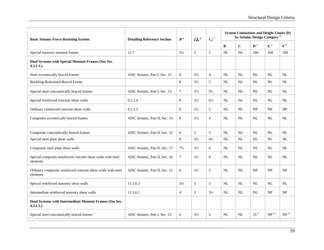
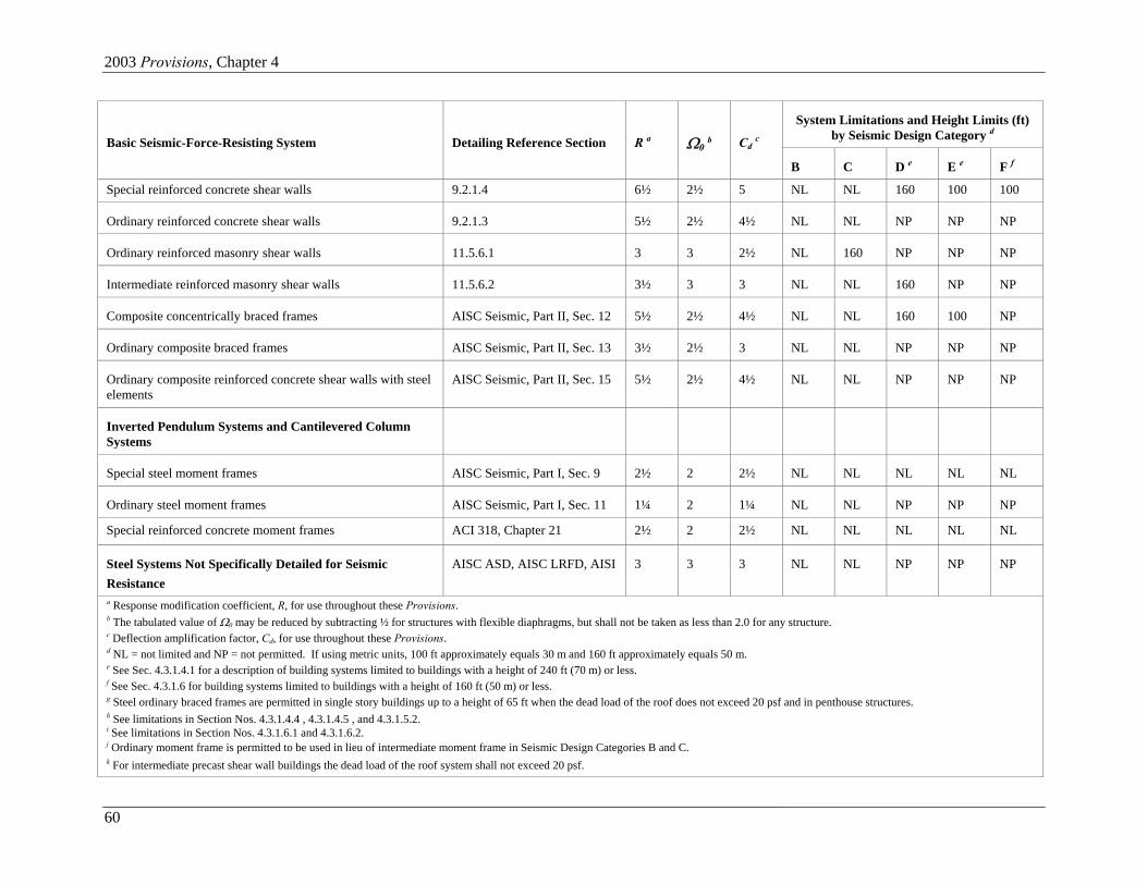
4.3.1 Selection and limitations. The basic lateral and vertical seismic-force-resisting system shall conform to one of the types indicated in Table 4.3-1 subject to the system limitations and height limits, based on Seismic Design Category, indicated in the table. Each type is subdivided based on types of vertical elements used to resist lateral seismic forces. The appropriate values of R, Ω0, and Cd indicated in Table 4.3-1 shall be used in determining the base shear, element design forces, and design story drift as indicated in these Provisions.
Seismic-force-resisting systems that are not contained in Table 4.3-1 shall be permitted if analytical and test data are submitted that establish the dynamic characteristics and demonstrate the lateral force resistance and energy dissipation capacity to be equivalent to the structural systems listed in Table 4.3-1 for equivalent values of R, Ω0, and Cd.
Additional limitations and framing requirements are indicated in this chapter and in elsewhere in these Provisions for structures assigned to the various Seismic Design Categories.
2003 Provisions, Chapter 4
56
Table 4.3-1 Design Coefficients and Factors for Basic Seismic-Force-Resisting Systems
System Limitations and Height Limits (ft)
by Seismic Design Category d Basic Seismic-Force-Resisting System
Detailing Reference Section
R a
Ω0 b
Cd c
B C
D e
E e
F f
Bearing Wall Systems Special reinforced concrete shear walls
9.2.1.6 5
2½
5
NL
NL
160
160
100
Ordinary reinforced concrete shear walls
9.2.1.4
4
2½
4
NL
NL
NP
NP
NP
Detailed plain concrete shear walls
9.2.1.2
2
2½
2
NL
NP
NP
NP
NP
Ordinary plain concrete shear walls
9.2.1.1
1½
2½
1½
NL
NP
NP
NP
NP
Intermediate precast shear walls 9.2.1.5
4
2½
4
NL
NL
40k
40k 40k
Ordinary precast shear walls
9.2.1.3
3
2½
3
NL
NP
NP
NP
NP
Special reinforced masonry shear walls
11.5.6.3
3½
2½
3½
NL
NL
160
160
100
Intermediate reinforced masonry shear walls
11.5.6.2
2½
2½
2¼
NL
NL
NP
NP
NP
Ordinary reinforced masonry shear walls
11.5.6.1
2
2½
1¾
NL
NP
NP
NP
NP
Detailed plain masonry shear walls
11.4.4.2
2
2½
1¾
NL
NP
NP
NP
NP
Ordinary plain masonry shear walls
11.4.4.1
1½
2½
1¼
NL
NP
NP
NP
NP
Prestressed masonry shear walls 11.9 1½ 2½ 1¾ NL NP NP NP NP Light-frame walls with shear panels
8.4, 12.3.3, 12.4
6½
3
4
NL
NL
65
65
65
Light-frame walls with diagonal braces
8.4.2
4
2
3½
NL
NL
65
65
65
Building Frame Systems
Steel eccentrically braced frames with moment-resisting connections at columns away from links
AISC Seismic, Part I, Sec. 15
8
2
4
NL
NL
160
160
100
Structural Design Criteria
57
System Limitations and Height Limits (ft)
by Seismic Design Category d Basic Seismic-Force-Resisting System
Detailing Reference Section
R a
Ω0 b
Cd c
B C
D e
E e
F f
Steel eccentrically braced frames with non-moment-resisting connections at columns away from links
AISC Seismic, Part I, Sec. 15 7 2 4 NL NL 160 160 100
Buckling-Restrained Braced Frames, non-moment- resisting beam-column connections
7
2
5½
NL
NL
160
160
100
Buckling-Restrained Braced Frames, moment-resisting Beam-column connections
8 2½ 5 NL NL 160 160 100
Special steel concentrically braced frames
AISC Seismic, Part I, Sec. 13
6
2
5
NL
NL
160
160
100
Ordinary steel concentrically braced frames
AISC Seismic, Part I, Sec. 14
5
2
4½
NL
NL
35 g
35 g
NP g
Special reinforced concrete shear walls
9.2.1.6
6
2½
5
NL
NL
160
160
100
Ordinary reinforced concrete shear walls
9.2.1.4
5
2½
4½
NL
NL
NP
NP
NP
Detailed plain concrete shear walls
9.2.1.2
2½
2½
2½
NL
NP
NP
NP
NP
Ordinary plain concrete shear walls
9.2.1.1
1½
2½
1½
NL
NP
NP
NP
NP
Intermediate precast shear walls 9.2.1.5 5 2½ 4½ NL NL 40k 40k 40k
Ordinary precast shear walls 9.2.1.3 4 2½ 4 NL NP NP NP NP Composite eccentrically braced frames
AISC Seismic, Part II, Sec. 14
8
2½
4
NL
NL
160
160
100
Composite concentrically braced frames
AISC Seismic, Part II, Sec. 12
5
2
4½
NL
NL
160
160
100
Ordinary composite braced frames
AISC Seismic, Part II, Sec. 13
3
2
3
NL
NL
NP
NP
NP
Composite steel plate shear walls
AISC Seismic, Part II, Sec. 17
6½
2½
5½
NL
NL
160
160
100
Special steel plate shear walls 7 2 6 NL NL 160 160 100 Special composite reinforced concrete shear walls with steel elements
AISC Seismic, Part II, Sec. 16
6
2½
5
NL
NL
160
160
100
Ordinary composite reinforced concrete shear walls with steel elements
AISC Seismic, Part II, Sec. 15
5
2½
4½
NL
NL
NP
NP
NP
2003 Provisions, Chapter 4
58
System Limitations and Height Limits (ft)
by Seismic Design Category d Basic Seismic-Force-Resisting System
Detailing Reference Section
R a
Ω0 b
Cd c
B C
D e
E e
F f
Special reinforced masonry shear walls 11.5.6.3 4½ 2½ 4 NL NL 160 160 100 Intermediate reinforced masonry shear walls
11.5.6.2
3
2½
2½
NL
NL
NP
NP
NP
Ordinary reinforced masonry shear walls
11.5.6.1
2
2½
2
NL
NP
NP
NP
NP
Detailed plain masonry shear walls 11.4.4.2 2 2½ 2 NL NP Np NP NP Ordinary plain masonry shear walls
11.4.4.1
1½
2½
1¼
NL
NP
NP
NP
NP
Prestressed masonry shear walls 11.9 1½ 2½ 1¾ NL NP NP NP NP Light-frame walls with shear panels
8.4, 12.3.3, 12.4
7
2½
4½
NL
NL
160
160
160
Moment Resisting Frame Systems
Special steel moment frames
AISC Seismic, Part I, Sec. 9
8
3
5½
NL
NL
NL
NL
NL
Special steel truss moment frames
AISC Seismic, Part I, Sec. 12
7
3
5½
NL
NL
160
100
NP
Intermediate steel moment frames
AISC Seismic, Part I, Sec. 10
4½
3
4
NL
NL
35 h
NP h
NP i
Ordinary steel moment frames
AISC Seismic, Part I, Sec. 11
3½
3
3
NL
NL
NP h
NP h
NP i
Special reinforced concrete moment frames
9.2.2.2 & ACI 318, Chapter 21
8
3
5½
NL
NL
NL
NL
NL
Intermediate reinforced concrete moment frames
9.2.2.3 & ACI 318, Chapter 21
5
3
4½
NL
NL
NP
NP
NP
Ordinary reinforced concrete moment frames
9.3.1 & ACI 318, Chapter 21
3
3
2½
NL
NP
NP
NP
NP
Special composite moment frames
AISC Seismic, Part II, Sec. 9
8
3
5½
NL
NL
NL
NL
NL
Intermediate composite moment frames
AISC Seismic, Part II, Sec. 10
5
3
4½
NL
NL
NP
NP
NP
Composite partially restrained moment frames
AISC Seismic, Part II, Sec. 8
6
3
5½
160
160
100
NP
NP
Ordinary composite moment frames
AISC Seismic, Part II, Sec. 11
3
3
2½
NL
NP
NP
NP
NP
Structural Design Criteria
59
System Limitations and Height Limits (ft)
by Seismic Design Category d Basic Seismic-Force-Resisting System
Detailing Reference Section
R a
Ω0 b
Cd c
B C
D e
E e
F f
Special masonry moment frames 11.7 5½ 3 5 NL NL 160 160 100 Dual Systems with Special Moment Frames (See Sec. 4.3.1.1.)
Steel eccentrically braced frames
AISC Seismic, Part I, Sec. 15
8
2½
4
NL
NL
NL
NL
NL
Buckling-Restrained Braced Frame
8
2½
5
NL
NL
NL
NL
NL
Special steel concentrically braced frames
AISC Seismic, Part I, Sec. 13
7
2½
5½
NL
NL
NL
NL
NL
Special reinforced concrete shear walls
9.2.1.4
8
2½
6½
NL
NL
NL
NL
NL
Ordinary reinforced concrete shear walls
9.2.1.3
6
2½
5
NL
NL
NP
NP
NP
Composite eccentrically braced frames
AISC Seismic, Part II, Sec. 14
8
2½
4
NL
NL
NL
NL
NL
Composite concentrically braced frames
AISC Seismic, Part II, Sec. 12
6
2
5
NL
NL
NL
NL
NL
Special steel plate shear walls 8 2½ 6½ NL NL NL NL NL Composite steel plate shear walls
AISC Seismic, Part II, Sec. 17
7½
2½
6
NL
NL
NL
NL
NL
Special composite reinforced concrete shear walls with steel elements
AISC Seismic, Part II, Sec. 16
7
2½
6
NL
NL
NL
NL
NL
Ordinary composite reinforced concrete shear walls with steel elements
AISC Seismic, Part II, Sec. 15
6
2½
5
NL
NL
NP
NP
NP
Special reinforced masonry shear walls
11.5.6.3
5½
3
5
NL
NL
NL
NL
NL
Intermediate reinforced masonry shear walls
11.5.6.2
4
3
3½
NL
NL
NL
NP
NP
Dual Systems with Intermediate Moment Frames (See Sec. 4.3.1.1.)
Special steel concentrically braced frames j
AISC Seismic, Part I, Sec. 13
6
2½
5
NL
NL
35 h
NP h, i
NP h, i
2003 Provisions, Chapter 4
60
System Limitations and Height Limits (ft)
by Seismic Design Category d Basic Seismic-Force-Resisting System
Detailing Reference Section
R a
Ω0 b
Cd c
B C
D e
E e
F f
Special reinforced concrete shear walls 9.2.1.4 6½ 2½ 5 NL NL 160 100 100 Ordinary reinforced concrete shear walls
9.2.1.3
5½
2½
4½
NL
NL
NP
NP
NP
Ordinary reinforced masonry shear walls
11.5.6.1
3
3
2½
NL
160
NP
NP
NP
Intermediate reinforced masonry shear walls
11.5.6.2
3½
3
3
NL
NL
160
NP
NP
Composite concentrically braced frames
AISC Seismic, Part II, Sec. 12
5½
2½
4½
NL
NL
160
100
NP
Ordinary composite braced frames
AISC Seismic, Part II, Sec. 13
3½
2½
3
NL
NL
NP
NP
NP
Ordinary composite reinforced concrete shear walls with steel elements
AISC Seismic, Part II, Sec. 15
5½
2½
4½
NL
NL
NP
NP
NP
Inverted Pendulum Systems and Cantilevered Column Systems
Special steel moment frames
AISC Seismic, Part I, Sec. 9
2½
2
2½
NL
NL
NL
NL
NL
Ordinary steel moment frames
AISC Seismic, Part I, Sec. 11
1¼
2
1¼
NL
NL
NP
NP
NP
Special reinforced concrete moment frames
ACI 318, Chapter 21
2½
2
2½
NL
NL
NL
NL
NL
Steel Systems Not Specifically Detailed for Seismic Resistance
AISC ASD, AISC LRFD, AISI
3
3
3
NL
NL
NP
NP
NP
a Response modification coefficient, R, for use throughout these Provisions. b The tabulated value of Ω0 may be reduced by subtracting ½ for structures with flexible diaphragms, but shall not be taken as less than 2.0 for any structure. c Deflection amplification factor, Cd, for use throughout these Provisions. d NL = not limited and NP = not permitted. If using metric units, 100 ft approximately equals 30 m and 160 ft approximately equals 50 m. e See Sec. 4.3.1.4.1 for a description of building systems limited to buildings with a height of 240 ft (70 m) or less. f See Sec. 4.3.1.6 for building systems limited to buildings with a height of 160 ft (50 m) or less. g Steel ordinary braced frames are permitted in single story buildings up to a height of 65 ft when the dead load of the roof does not exceed 20 psf and in penthouse structures. h See limitations in Section Nos. 4.3.1.4.4 , 4.3.1.4.5 , and 4.3.1.5.2. i See limitations in Section Nos. 4.3.1.6.1 and 4.3.1.6.2. j Ordinary moment frame is permitted to be used in lieu of intermediate moment frame in Seismic Design Categories B and C. k For intermediate precast shear wall buildings the dead load of the roof system shall not exceed 20 psf.
Structural Design Criteria
61
4.3.1.1 Dual system. For a dual system, the moment frame shall be capable of resisting at least 25 percent of the design forces. The total seismic force resistance is to be provided by the combination of the moment frame and the shear walls or braced frames in proportion to their rigidities.
4.3.1.2 Combinations of framing systems. Different seismic-force-resisting systems are permitted along the two orthogonal axes of the structure. Combinations of seismic-force-resisting systems shall comply with the requirements of this section.
4.3.1.2.1 R and Ω0 factors. In any given direction, the value of R at any story shall not exceed the lowest value of R in the same direction above that story excluding penthouses. For other than dual systems, where a combination of different structural systems is utilized to resist lateral forces in the same direction, the value of R used in that direction shall not be greater than the least value of any of the systems utilized in the same direction. If a system, other than a dual system, with a value of R less than 5 is used as part of the seismic-force-resisting system in any direction of the structure, the lowest such value shall be used for the entire structure. The system overstrength factor, Ω0, in the direction under consideration at any story shall not be less than the largest value of this factor for the seismic-force-resisting system in the same direction considered above that story.
Exceptions: The requirements of this section need not be applied where one of the following conditions is satisfied:
1. Supported structural systems with a weight equal to or less than 10 percent of the weight of the structure.
2. Detached one- and two-family dwellings of light-frame construction.
4.3.1.2.2 Detailing of common components. The detailing requirements for the higher response modification coefficient, R, shall be used for structural components common to systems having different response modification coefficients.
4.3.1.3 Seismic Design Categories B and C. The structural framing system for structures assigned to Seismic Design Category B or C shall comply with the system limitations and building height limits in Table 4.3-1.
4.3.1.4 Seismic Design Category D. The structural framing system for structures assigned to Seismic Design Category D shall comply with Sec. 4.3.1.3 and the additional requirements of this section.
4.3.1.4.1 Building height limits. The height limits in Table 4.3-1 are permitted to be increased to 240 ft (70 m) in buildings that have steel braced frames or concrete cast-in-place shear walls if such buildings are configured such that the braced frames or shear walls arranged in any one plane conform to the following:
1. The braced frames or cast-in-place special reinforced concrete shear walls in any one plane shall resist no more than 60 percent of the total seismic forces in each direction, neglecting torsional effects, and
2. The seismic force in any braced frame or shear wall resulting from torsional effects shall not exceed 20 percent of the total seismic force in that braced frame or shear wall.
4.3.1.4.2 Interaction effects. Moment resisting frames that are enclosed or adjoined by more rigid elements not considered to be part of the seismic-force-resisting system shall be designed so that the action or failure of those elements will not impair the vertical load and seismic force resisting capability of the frame. The design shall consider and provide for the effect of these rigid elements on the structural system at structure deformations corresponding to the design story drift, ∆, as determined in Sec. 5.2.6.1. In addition, the effects of these elements shall be considered where determining whether a structure has one or more of the irregularities defined in Sec. 4.3.2.
4.3.1.4.3 Special moment frames. A special moment frame that is used but not required by Table 4.3-1 is permitted to be discontinued and supported by a more rigid system with a lower response
2003 Provisions, Chapter 4
62
modification coefficient, R, provided the requirements of Sec. 4.6.1.6 and 4.6.3.2 are met. Where a special moment frame is required by Table 4.3-1 as part of a dual system, the frame shall be continuous to the foundation.
For structures with seismic-force-resisting systems in any direction comprised solely of special moment frames, the seismic-force-resisting system shall be configured such that the value of ρ is 1.0
4.3.1.4.4 Single Story Steel Ordinary and Intermediate Moment Frame Limitations. Single story steel OMF and IMF are permitted up to a height of 65ft. (19.8 m) where the dead load supported by and tributary to the roof does not exceed 20 psf. In addition the dead loads, tributary to the moment frame, of the exterior wall more than 35 ft. (10.8 m) above the base shall not exceed 20 psf.
4.3.1.4.5 Other Steel Ordinary and Intermediate Moment Frame Limitations. Steel OMF not meeting the limitations in Sec. 4.3.1.4.4 are permitted within light frame construction up to a height of 35 ft. (10.8m) where neither the roof nor the floor dead load supported by and tributary to the moment frames exceeds 35 psf. In addition the dead load of the exterior walls tributary to the moment frame shall not exceed 20 psf.
Steel IMF not meeting the limitations in Sec. 4.3.1.4.4 are permitted to a height of 35ft. (10.8m)
4.3.1.5 Seismic Design Category E. The structural framing system for a structure assigned to Seismic Design Category E shall comply with Sec. 4.3.1.4 and the additional requirements of this section.
4.3.1.5.1 Plan or vertical irregularities. Structures having plan irregularity Type 1b of Table 4.3-2 or vertical irregularities Type 1b or 5 of Table 4.3-3 shall not be permitted.
4.3.1.5.2 Steel Intermediate Moment Frame Limitations. Steel IMF not meeting the limitations in Section 4.3.1.4.4 are permitted to a height of 35 ft. (10.8 m) providing neither the roof nor the floor dead load supported by and tributary to the moment frames exceeds 35 psf. In addition the dead load of the exterior walls tributary to the moment frame shall not exceed 20 psf.
4.3.1.6 Seismic Design Category F. The structural framing system for a structure assigned to Seismic Design Category F shall comply with Sec. 4.3.1.5 and the additional requirements of this section. The height limits given in Sec. 4.3.1.4.1 shall be reduced from 240 ft to 160 ft (70 to 50 m).
4.3.1.6.1 Single Story Steel Ordinary and Intermediate Moment Frame Limitations. Single story steel OMF and IMF are permitted up to a height of 65’ where the dead load supported by and tributary to the roof does not exceed 20 psf. In addition the dead load of the exterior walls tributary to the moment frame shall not exceed 20 psf. 4.3.1.6.2 Other Steel Intermediate Moment Frame Limitations. Steel IMF not meeting the limitations in Sec. 4.3.1.4.4 are permitted in light frame construction to a height of 35 ft. (10.8 m) providing neither the roof nor the floor dead load supported by and tributary to the moment frames exceeds 35 psf. In addition the dead load of the exterior walls tributary to the moment frame shall not exceed 20 psf.
4.3.2 Configuration. Diaphragm behavior shall be classified as indicated in this section. Structures shall be classified as regular or irregular, based on the plan and vertical configuration, in accordance with this section.
4.3.2.1 Diaphragm flexibility. A diaphragm shall be considered flexible for determining distribution of horizontal forces when the computed maximum in-plane deflection of the diaphragm itself under lateral load is more than two times the average deflection of adjoining vertical elements of the lateral force-resisting system of the associated story under equivalent tributary lateral load. The loadings used for this calculation shall be those prescribed by Sec. 5.2.
Structural Design Criteria
63
Exception: Diaphragms constructed of untopped steel decking, wood structural panels, or similar panelized construction shall be considered flexible in structures having concrete or masonry shear walls.
4.3.2.2 Plan irregularity. Structures having one or more of the features listed in Table 4.3-2 shall be designated as having plan structural irregularity and shall comply with the requirements in the sections referenced in Table 4.3-2.
4.3.2.3 Vertical irregularity. Structures having one or more of the features listed in Table 4.3-3 shall be designated as having vertical irregularity and shall comply with the requirements in the sections referenced in Table 4.3-3.
Exceptions:
1. Structural irregularities of Types 1a, 1b, or 2 in Table 4.3-3 do not apply where no story drift ratio under design lateral load is greater than 130 percent of the story drift ratio of the next story above. Torsional effects need not be considered in the calculation of story drifts for the purpose of this determination. The story drift ratio relationship for the top 2 stories of the structure are not required to be evaluated.
2. Irregularity Types 1a, 1b, and 2 of Table 4.3-3 are not required to be considered for 1-story structures or for 2-story structures assigned to Seismic Design Category B, C, or D.
2003 Provisions, Chapter 4
64
Table 4.3-2 Plan Structural Irregularities
Irregularity Type and Description
Reference
Section
Seismic Design
Category Application
1a
Torsional Irregularity—to be considered when diaphragms are not flexible Torsional irregularity shall be considered to exist when the maximum story drift, computed including accidental torsion, at one end of the structure transverse to an axis is more than 1.2 times the average of the story drifts at the two ends of the structure.
4.4.1
4.6.3.2
5.2.4.3 and
5.2.6.1
D, E, and F
D, E, and F
C, D, E, and F
1b
Extreme Torsional Irregularity—to be considered when diaphragms are not flexible Extreme torsional irregularity shall be considered to exist when the maximum story drift, computed including accidental torsion, at one end of the structure transverse to an axis is more than 1.4 times the average of the story drifts at the two ends of the structure.
4.3.1.5.1
4.4.1
4.6.3.2
5.2.4.3 and 5.2.6.1
E and F
D D
C, D, E, and F
2
Re-entrant Corners Plan configurations of a structure and its lateral force-resisting system contain re-entrant corners, where both projections of the structure beyond a re-entrant corner are greater than 15 percent of the plan dimension of the structure in the given direction.
4.6.3.2
D, E, and F
3
Diaphragm Discontinuity Diaphragms with abrupt discontinuities or variations in stiffness, including those having cutout or open areas greater than 50 percent of the gross enclosed diaphragm area, or changes in effective diaphragm stiffness of more than 50 percent from one story to the next.
4.6.3.2
D, E, and F
4
Out-of-Plane Offsets Discontinuities in a lateral force resistance path, such as out-of-plane offsets of the vertical elements.
4.6.1.7
4.6.3.2
B, C, D, E, and F
D, E, and F
5
Nonparallel Systems The vertical lateral force-resisting elements are not parallel to or symmetric about the major orthogonal axes of the seismic-force-resisting system.
4.4.2.2
C, D, E, and F
Structural Design Criteria
65
Table 4.3-3 Vertical Structural Irregularities
Irregularity Type and Description
Reference
Section
Seismic Design
Category Application
1a
Stiffness Irregularity—Soft Story A soft story is one in which the lateral stiffness is less than 70 percent of that in the story above or less than 80 percent of the average stiffness of the three stories above.
4.4.1
D, E, and F
1b
Stiffness Irregularity—Extreme Soft Story An extreme soft story is one in which the lateral stiffness is less than 60 percent of that in the story above or less than 70 percent of the average stiffness of the three stories above.
4.3.1.5.1
4.4.1
E and F
D
2
Weight (Mass) Irregularity Mass irregularity shall be considered to exist where the effective mass of any story is more than 150 percent of the effective mass of an adjacent story. A roof that is lighter than the floor below need not be considered.
4.4.1
D, E, and F
3
Vertical Geometric Irregularity Vertical geometric irregularity shall be considered to exist where the horizontal dimension of the lateral force-resisting system in any story is more than 130 percent of that in an adjacent story.
4.4.1
D, E, and F
4
In-Plane Discontinuity in Vertical Lateral Force Resisting Elements An in-plane offset of the lateral force-resisting elements greater than the length of those elements or a reduction in stiffness of the resisting element in the story below.
4.6.1.7
4.6.3.2
B, C, D, E, and F
D, E, and F
5
Discontinuity in Capacity—Weak Story A weak story is one in which the story lateral strength is less than 80 percent of that in the story above. The story strength is the total strength of all seismic-resisting elements sharing the story shear for the direction under consideration.
4.3.1.5.1
4.6.1.6
E and F
B, C, and D
4.3.3 Redundancy. A redundancy factor, ρ, shall be assigned to the seismic force-resisting system in each of two orthogonal directions for all structures in accordance with this section, based on the extent of structural redundancy inherent in the seismic-force-resisting system.
4.3.3.1 Seismic Design Categories B, and C. For structures assigned to Seismic Design Category B or C, the value of ρ may be taken as 1.0.
4.3.3.2 Seismic Design Categories D, E, and F. For structures assigned to Seismic Design Category D, E, or F, ρ shall be permitted to be taken as 1.0, provided that at each story resisting more than 35 percent of the base shear in the direction of interest the seismic-force-resisting system meets the following redundancy requirements:
2003 Provisions, Chapter 4
66
1. Systems with braced frames: Removal of an individual brace, or connection thereto, would not result in more than a 33 percent reduction in story strength, nor create an extreme torsional irregularity (plan structural irregularity Type 1b).
2. Systems with moment frames: Loss of moment resistance at the beam-to-column connections at both ends of a single beam would not result in more than a 33 percent reduction in story strength, nor create an extreme torsional irregularity (plan structural irregularity Type 1b).
3. Systems with shear walls or wall piers: Removal of a shear wall or wall pier with a height-to-length-ratio greater than 1.0 within any story, or collector connections thereto, would not result in more that a 33 percent reduction in story strength, nor create an extreme torsional irregularity (plan structural irregularity Type 1b).
4. All other systems: No requirements.
For structures not meeting items 1,2,3, and 4 above permitting ρ equal to 1.0, ρ shall be taken as 1.3.
Exception: The structure shall be permitted to be designed using a ρ taken as 1.0, provided that at each story that resists more than 35 percent of the base shear the seismic force-resisting system is regular in plan with at least two bays of primary seismic force-resisting elements located at the perimeter framing on each side of the structure in each orthogonal direction. The number of bays for a shear wall shall be calculated as the length of wall divided by the story height.
4.4 STRUCTURAL ANALYSIS
A structural analysis in accordance with the requirements of this section shall be made for all structures. All members of the structure’s seismic-force-resisting system and their connections shall have adequate strength to resist the forces, QE, predicted by the analysis, in combination with other loads as required by Sec. 4.2.2.
4.4.1 Procedure selection. The structural analysis required by Sec. 4.4 shall consist of one of the types permitted in Table 4.4-1, based on the assigned Seismic Design Category and the structural characteristics (seismic-force-resisting system, fundamental period of vibration, and configuration). With the approval of the authority having jurisdiction, use of an alternative, generally accepted procedure shall be permitted.
Structural Design Criteria
67
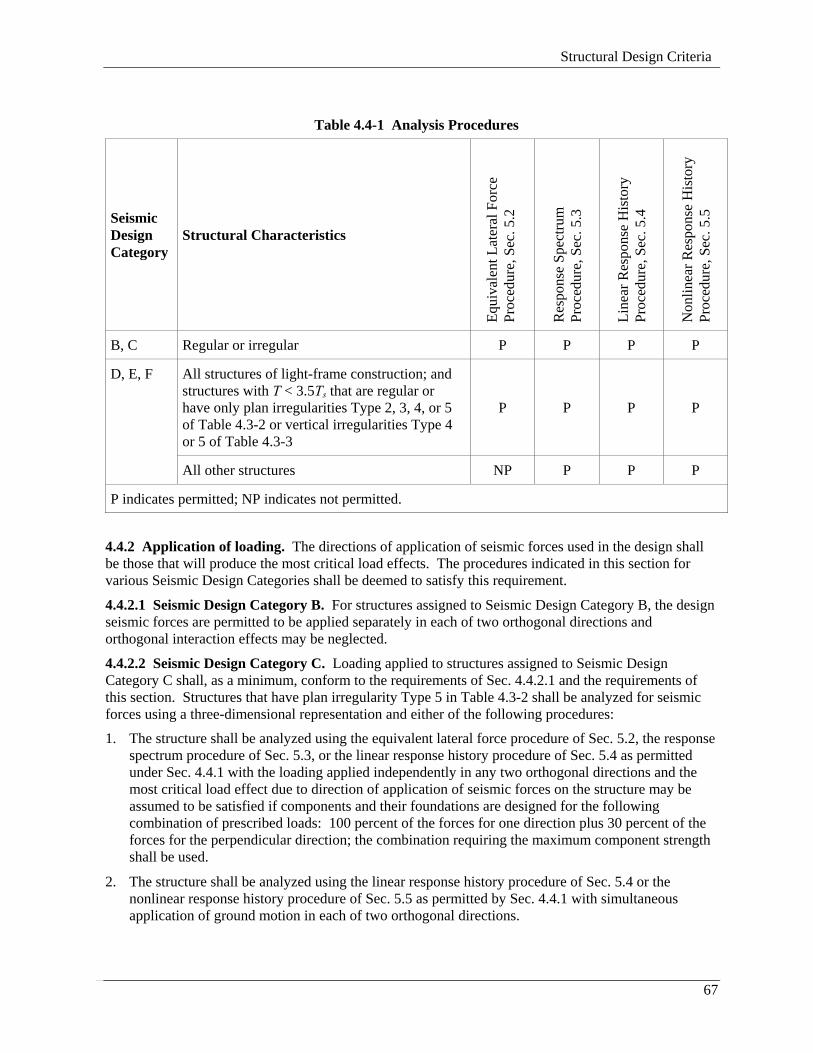
Table 4.4-1 Analysis Procedures
Seismic Design Category
Structural Characteristics
Equi
vale
nt L
ater
al F
orce
Pr
oced
ure,
Sec
. 5.2
Res
pons
e Sp
ectru
m
Proc
edur
e, S
ec. 5
.3
Line
ar R
espo
nse
His
tory
Pr
oced
ure,
Sec
. 5.4
Non
linea
r Res
pons
e H
isto
ry
Proc
edur
e, S
ec. 5
.5
B, C
Regular or irregular
P
P
P
P
All structures of light-frame construction; and structures with T < 3.5Ts that are regular or have only plan irregularities Type 2, 3, 4, or 5 of Table 4.3-2 or vertical irregularities Type 4 or 5 of Table 4.3-3
P
P
P
P
D, E, F
All other structures
NP
P
P
P
P indicates permitted; NP indicates not permitted.
4.4.2 Application of loading. The directions of application of seismic forces used in the design shall be those that will produce the most critical load effects. The procedures indicated in this section for various Seismic Design Categories shall be deemed to satisfy this requirement.
4.4.2.1 Seismic Design Category B. For structures assigned to Seismic Design Category B, the design seismic forces are permitted to be applied separately in each of two orthogonal directions and orthogonal interaction effects may be neglected.
4.4.2.2 Seismic Design Category C. Loading applied to structures assigned to Seismic Design Category C shall, as a minimum, conform to the requirements of Sec. 4.4.2.1 and the requirements of this section. Structures that have plan irregularity Type 5 in Table 4.3-2 shall be analyzed for seismic forces using a three-dimensional representation and either of the following procedures:
1. The structure shall be analyzed using the equivalent lateral force procedure of Sec. 5.2, the response spectrum procedure of Sec. 5.3, or the linear response history procedure of Sec. 5.4 as permitted under Sec. 4.4.1 with the loading applied independently in any two orthogonal directions and the most critical load effect due to direction of application of seismic forces on the structure may be assumed to be satisfied if components and their foundations are designed for the following combination of prescribed loads: 100 percent of the forces for one direction plus 30 percent of the forces for the perpendicular direction; the combination requiring the maximum component strength shall be used.
2. The structure shall be analyzed using the linear response history procedure of Sec. 5.4 or the nonlinear response history procedure of Sec. 5.5 as permitted by Sec. 4.4.1 with simultaneous application of ground motion in each of two orthogonal directions.
2003 Provisions, Chapter 4
68
4.4.2.3 Seismic Design Categories D, E, and F. Structures assigned to Seismic Design Category D, E, or F shall be analyzed for seismic forces using a three-dimensional representation and either of the procedures described in Sec. 4.4.2.2. Two dimensional analysis shall be permitted where diaphragms are flexible and the structure does not have plan irregularity Type 5 of Table 4.3-2.
4.5 DEFORMATION REQUIREMENTS
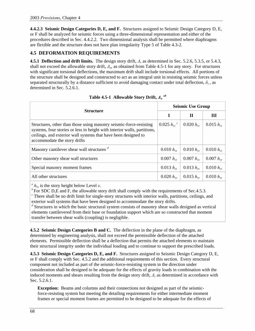
4.5.1 Deflection and drift limits. The design story drift, ∆, as determined in Sec. 5.2.6, 5.3.5, or 5.4.3, shall not exceed the allowable story drift, ∆a, as obtained from Table 4.5-1 for any story. For structures with significant torsional deflections, the maximum drift shall include torsional effects. All portions of the structure shall be designed and constructed to act as an integral unit in resisting seismic forces unless separated structurally by a distance sufficient to avoid damaging contact under total deflection, δx , as determined in Sec. 5.2.6.1.
Table 4.5-1 Allowable Story Drift, ∆a ab
Seismic Use Group Structure
I
II
III Structures, other than those using masonry seismic-force-resisting systems, four stories or less in height with interior walls, partitions, ceilings, and exterior wall systems that have been designed to accommodate the story drifts
0.025 hsx c
0.020 hsx
0.015 hsx
Masonry cantilever shear wall structures d
0.010 hsx
0.010 hsx
0.010 hsx
Other masonry shear wall structures
0.007 hsx
0.007 hsx
0.007 hsx
Special masonry moment frames
0.013 hsx
0.013 hsx
0.010 hsx
All other structures
0.020 hsx
0.015 hsx
0.010 hsx
a hsx is the story height below Level x. b For SDC D,E and F, the allowable story drift shall comply with the requirements of Sec.4.5.3. c There shall be no drift limit for single-story structures with interior walls, partitions, ceilings, and exterior wall systems that have been designed to accommodate the story drifts. d Structures in which the basic structural system consists of masonry shear walls designed as vertical elements cantilevered from their base or foundation support which are so constructed that moment transfer between shear walls (coupling) is negligible.
4.5.2 Seismic Design Categories B and C. The deflection in the plane of the diaphragm, as determined by engineering analysis, shall not exceed the permissible deflection of the attached elements. Permissible deflection shall be a deflection that permits the attached elements to maintain their structural integrity under the individual loading and to continue to support the prescribed loads.
4.5.3 Seismic Design Categories D, E, and F. Structures assigned to Seismic Design Category D, E, or F shall comply with Sec. 4.5.2 and the additional requirements of this section. Every structural component not included as part of the seismic-force-resisting system in the direction under consideration shall be designed to be adequate for the effects of gravity loads in combination with the induced moments and shears resulting from the design story drift, ∆, as determined in accordance with Sec. 5.2.6.1.
Exception: Beams and columns and their connections not designed as part of the seismic-force-resisting system but meeting the detailing requirements for either intermediate moment frames or special moment frames are permitted to be designed to be adequate for the effects of
Structural Design Criteria
69
gravity loads in combination with the induced moments and shears resulting from the deformation of the building under the application of the design seismic forces.
Where determining the moments and shears induced in components that are not included as part of the seismic-force-resisting system in the direction under consideration, the stiffening effects of adjoining rigid structural and nonstructural elements shall be considered and a rational value of member and restraint stiffness shall be used.
For systems with moment frames the design story drift ∆, as determined in Sec. 5.2.6, 5.3.5, or 5.4.3, shall not exceed ∆a /ρ for any story. ρ shall be calculated per Sec.4.3.3.
4.6 DESIGN AND DETAILING REQUIREMENTS
The design and detailing of the components of the seismic-force-resisting system shall comply with the requirements of this section. Foundation design shall comply with the applicable requirements of Chapter 7. The materials and the systems composed of those materials shall comply with applicable requirements and limitations found elsewhere in these Provisions.
4.6.1 Seismic Design Category B. The design and detailing of structures assigned to Seismic Design Category B shall comply with the requirements of this section.
4.6.1.1 Connections. All parts of the structure between separation joints shall be interconnected, and the connections shall be capable of transmitting the seismic force, Fp, induced by the parts being connected. Any smaller portion of the structure shall be tied to the remainder of the structure with elements having a strength of 0.133 times SDS times the weight of the smaller portion or 5 percent of the portion's weight, whichever is greater.
A positive connection for resisting a horizontal force acting parallel to the member shall be provided for each beam, girder, or truss to its support. The connection shall have a minimum strength of 5 percent of the reaction due to dead load and live load.
4.6.1.2 Anchorage of concrete or masonry walls. Concrete or masonry walls shall be connected, using reinforcement or anchors, to the roof and all floors and members that provide lateral support for the wall or that are supported by the wall. The connection shall be capable of resisting a seismic lateral force induced by the wall of 100 pounds per lineal foot (1500 N/m ). Walls shall be designed to resist bending between connections where the spacing exceeds 4 ft (1.2 m).
4.6.1.3 Bearing walls. Exterior and interior bearing walls and their anchorage shall be designed for a force equal to 40 percent of SDS times the weight of wall, Wc, normal to the surface, with a minimum force of 10 percent of the weight of the wall. Interconnection of wall elements and connections to supporting framing systems shall have sufficient ductility, rotational capacity, or strength to resist shrinkage, thermal changes, and differential foundation settlement where combined with seismic forces.
4.6.1.4 Openings. Where openings occur in shear walls, diaphragms or other plate-type elements, reinforcement at the edges of the openings shall be designed to transfer the stresses into the structure. The edge reinforcement shall extend into the body of the wall or diaphragm a distance sufficient to develop the force in the reinforcement.
4.6.1.5 Inverted pendulum-type structures. Supporting columns or piers of inverted pendulum-type structures shall be designed for the bending moment calculated at the base determined using the procedures given in Sec. 5.2 and varying uniformly to a moment at the top equal to one-half the calculated bending moment at the base.
4.6.1.6 Discontinuities in vertical system. Structures with vertical irregularity Type 5 as defined in Table 4.3-3, shall not be over the lesser of 2 stories or 30 ft (9 m) in height where the weak story has a calculated strength of less than 65 percent of the strength of the story above.
2003 Provisions, Chapter 4
70
Exception: The height limit shall not apply where the weak story is capable of resisting a total seismic force equal to 75 percent of the deflection amplification factor, Cd, times the design force prescribed in Sec. 5.2.
4.6.1.7 Columns supporting discontinuous walls or frames. Columns supporting discontinuous walls or frames of structures having plan irregularity Type 4 of Table 4.3-2 or vertical irregularity Type 4 of Table 4.3-3 shall have the design strength to resist the maximum axial force that can develop in accordance with Sec. 4.2.2.2.
4.6.1.8 Collector elements. Collector elements shall be provided and shall be capable of transferring the seismic forces originating in other portions of the structure to the element providing the resistance to those forces.
4.6.1.9 Diaphragms. Floor and roof diaphragms shall be designed to resist the following seismic forces: A minimum force equal to 20 percent of SDS times the weight of the diaphragm and other elements of the structure attached thereto plus the portion of the seismic shear force at that level, Vx, required to be transferred to the components of the vertical seismic-force-resisting system because of offsets or changes in stiffness of the vertical components above and below the diaphragm.
Diaphragms shall provide for both the shear and bending stresses resulting from these forces. Diaphragms shall have ties or struts to distribute the wall anchorage forces into the diaphragm. Diaphragm connections shall be positive, mechanical or welded type connections.
4.6.1.10 Anchorage of nonstructural systems. Where required by Chapter 6, all portions or components of the structure shall be anchored for the seismic force, Fp, prescribed therein.
4.6.2 Seismic Design Category C. Structures assigned to Seismic Design Category C shall comply with the requirements of Sec. 4.6.1 and the requirements of this section.
4.6.2.1 Anchorage of concrete or masonry walls. In addition to the requirements of Sec. 4.6.1.2, concrete or masonry walls shall be anchored in accordance with this section. The anchorage shall provide a positive direct connection between the wall and floor, roof, or supporting member capable of resisting horizontal forces specified in this section for structures with flexible diaphragms or of Sec. 6.2.2 (using ap equal to 1.0 and Rp equal to 2.5) for structures with diaphragms that are not flexible.
Anchorage of walls to flexible diaphragms shall have the strength to develop the out-of-plane force given by Eq. 4.6-1 as follows:
0.8p DS pS IWF = (4.6-1) where:
Fp = the design force in the individual anchors,
SDS = the design spectral response acceleration parameter at short periods as defined in Sec. 3.3.3,
I = the occupancy importance factor as defined in Sec. 1.3, and
Wp = the weight of the wall tributary to the anchor.
Diaphragms shall be provided with continuous ties or struts between diaphragm chords to distribute these anchorage forces into the diaphragms. Added chords are permitted to be used to form subdiaphragms to transmit the anchorage forces to the main continuous cross ties. The maximum length-to-width ratio of the structural subdiaphragm shall be 2.5 to 1. Connections and anchorages capable of resisting the prescribed forces shall be provided between the diaphragm and the attached components. Connections shall extend into the diaphragm a sufficient distance to develop the force transferred into the diaphragm.
Structural Design Criteria
71
In wood diaphragms, the continuous ties shall be in addition to the diaphragm sheathing. Anchorage shall not be accomplished by use of toe nails or nails subject to withdrawal nor shall wood ledgers of framing be used in cross-grain bending or cross-grain tension. The diaphragm sheathing shall not be considered as effectively providing the ties or struts required by this section.
In metal deck diaphragms, the metal deck shall not be used as the continuous ties required by this section in the direction perpendicular to the deck span.
Diaphragm to wall anchorage using embedded straps shall be attached to or hooked around the reinforcing steel or otherwise terminated so as to effectively transfer forces to the reinforcing steel.
4.6.2.2 Collector elements. In addition to the requirements of Sec. 4.6.1.8, collector elements, splices, and their connections to resisting elements shall be designed to resist the forces defined in Sec. 4.2.2.2.
Exception: In structures or portions thereof braced entirely by light-frame shear walls, collector elements, splices, and connections to resisting elements are permitted to be designed to resist the forces determined in accordance with Sec. 4.6.3.4.
4.6.3 Seismic Design Categories D, E, and F. Structures assigned to Seismic Design Category D, E, or F shall conform to the requirements of Sec. 4.6.2 and to the requirements of this section.
4.6.3.1 Vertical seismic forces. The vertical component of earthquake ground motion shall be considered in the design of horizontal cantilever and horizontal prestressed components. The load combinations used in evaluating such components shall include E as defined by Eq. 4.2-1 and 4.2-2. Horizontal cantilever structural components shall be designed for a minimum net upward force of 0.2 times the dead load in addition to the applicable load combinations of Sec. 4.2.2.
4.6.3.2 Plan or vertical irregularities. The design shall consider the potential for adverse effects where the ratio of the strength provided in any story to the strength required is significantly less than that ratio for the story immediately above and the strengths shall be adjusted to compensate for this effect.
For structures having a plan structural irregularity of Type 1a, 1b, 2, 3, or 4 in Table 4.3-2 or a vertical structural irregularity of Type 4 in Table 4.3-3, the design forces determined from the structural analysis performed in accordance with Sec. 4.4 shall be increased 25 percent for connections of diaphragms to vertical elements and to collectors. Collector forces determined in accordance with Sec. 4.6.3.4 (but not those determined in accordance with Sec. 4.2.2.2) shall be subject to this increase.
4.6.3.3 Collector elements. In addition to the requirements of Sec. 4.6.2.2, collector elements, splices, and their connections to resisting elements shall resist the forces determined in accordance with Sec. 4.6.3.4.
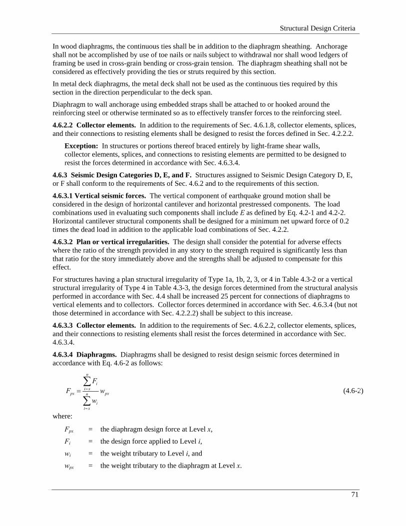
4.6.3.4 Diaphragms. Diaphragms shall be designed to resist design seismic forces determined in accordance with Eq. 4.6-2 as follows:
n
ii x
px pxn
ii x
FF w
w
=
=
=∑
∑ (4.6-2)
where:
Fpx = the diaphragm design force at Level x,
Fi = the design force applied to Level i,
wi = the weight tributary to Level i, and
wpx = the weight tributary to the diaphragm at Level x.
2003 Provisions, Chapter 4
72
The force determined from Eq. 4.6-2 need not exceed 0.4SDSIwpx but shall not be less than 0.2SDSIwpx. Where the diaphragm is required to transfer design seismic force from the vertical-resisting elements above the diaphragm to other vertical-resisting elements below the diaphragm due to offsets in the placement of the elements or to changes in relative lateral stiffness in the vertical elements, these forces shall be added to those determined from Eq. 4.6-2.