Embed Size (px)
Citation preview
4-1
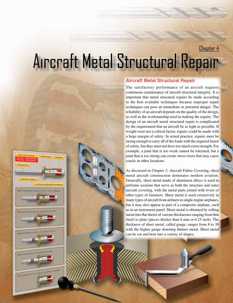
Aircraft Metal Structural RepairThe satisfactory performance of an aircraft requires continuous maintenance of aircraft structural integrity. It is important that metal structural repairs be made according to the best available techniques because improper repair techniques can pose an immediate or potential danger. The reliability of an aircraft depends on the quality of the design, as well as the workmanship used in making the repairs. The design of an aircraft metal structural repair is complicated by the requirement that an aircraft be as light as possible. If weight were not a critical factor, repairs could be made with a large margin of safety. In actual practice, repairs must be strong enough to carry all of the loads with the required factor of safety, but they must not have too much extra strength. For example, a joint that is too weak cannot be tolerated, but a joint that is too strong can create stress risers that may cause cracks in other locations.
As discussed in Chapter 3, Aircraft Fabric Covering, sheet metal aircraft construction dominates modern aviation. Generally, sheet metal made of aluminum alloys is used in airframe sections that serve as both the structure and outer aircraft covering, with the metal parts joined with rivets or other types of fasteners. Sheet metal is used extensively in many types of aircraft from airliners to single engine airplanes, but it may also appear as part of a composite airplane, such as in an instrument panel. Sheet metal is obtained by rolling metal into flat sheets of various thicknesses ranging from thin (leaf) to plate (pieces thicker than 6 mm or 0.25 inch). The thickness of sheet metal, called gauge, ranges from 8 to 30 with the higher gauge denoting thinner metal. Sheet metal can be cut and bent into a variety of shapes.
Aircraft Metal Structural RepairChapter 4
4-2
Damage to metal aircraft structures is often caused by corrosion, erosion, normal stress, and accidents and mishaps. Sometimes aircraft structure modifications require extensive structural rework. For example, the installation of winglets on aircraft not only replaces a wing tip with a winglet, but also requires extensive reinforcing of the wing structure to carry additional stresses.
Numerous and varied methods of repairing metal structural portions of an aircraft exist, but no set of specific repair patterns applies in all cases. The problem of repairing a damaged section is usually solved by duplicating the original part in strength, kind of material, and dimensions. To make a structural repair, the aircraft technician needs a good working knowledge of sheet metal forming methods and techniques. In general, forming means changing the shape by bending and forming solid metal. In the case of aluminum, this is usually done at room temperature. All repair parts are shaped to fit in place before they are attached to the aircraft or component.
Forming may be a very simple operation, such as making a single bend or a single curve, or it may be a complex operation, requiring a compound curvature. Before forming a part, the aircraft technician must give some thought to the complexity of the bends, the material type, the material thickness, the material temper, and the size of the part being fabricated. In most cases, these factors determine which forming method to use. Types of forming discussed in this chapter include bending, brake forming, stretch forming, roll forming, and spinning. The aircraft technician also needs a working knowledge of the proper use of the tools and equipment used in forming metal.
In addition to forming techniques, this chapter introduces the airframe technician to the tools used in sheet metal construction and repair, structural fasteners and their installation, how to inspect, classify, and assess metal structural damage, common repair practices, and types of repairs.
The repairs discussed in this chapter are typical of those used in aircraft maintenance and are included to introduce some of the operations involved. For exact information about specific repairs, consult the manufacturer’s maintenance or structural repair manuals (SRM). General repair instructions are also discussed in Advisory Circular (AC) 43.13.1, Acceptable Methods, Techniques, and Practices—Aircraft Inspection and Repair.
Stresses in Structural MembersAn aircraft structure must be designed so that it accepts all of the stresses imposed upon it by the flight and ground loads without any permanent deformation. Any repair made must
accept the stresses, carry them across the repair, and then transfer them back into the original structure. These stresses are considered as flowing through the structure, so there must be a continuous path for them, with no abrupt changes in cross-sectional areas along the way. Abrupt changes in cross-sectional areas of aircraft structure that are subject to cycle loading or stresses result in a stress concentration that may induce fatigue cracking and eventual failure. A scratch or gouge in the surface of a highly stressed piece of metal causes a stress concentration at the point of damage and could lead to failure of the part. Forces acting on an aircraft, whether it is on the ground or in flight, introduce pulling, pushing, or twisting forces within the various members of the aircraft structure. While the aircraft is on the ground, the weight of the wings, fuselage, engines, and empennage causes forces to act downward on the wing and stabilizer tips, along the spars and stringers, and on the bulkheads and formers. These forces are passed from member to member causing bending, twisting, pulling, compression, and shearing forces.
As the aircraft takes off, most of the forces in the fuselage continue to act in the same direction; because of the motion of the aircraft, they increase in intensity. The forces on the wingtips and the wing surfaces, however, reverse direction; instead of being downward forces of weight, they become upward forces of lift. The forces of lift are exerted first against the skin and stringers, then are passed on to the ribs, and finally are transmitted through the spars to be distributed through the fuselage. The wings bend upward at their ends and may flutter slightly during flight. This wing bending cannot be ignored by the manufacturer in the original design and construction and cannot be ignored during maintenance. It is surprising how an aircraft structure composed of structural members and skin rigidly riveted or bolted together, such as a wing, can bend or act so much like a leaf spring.
The six types of stress in an aircraft are described as tension, compression, shear, bearing, bending, and torsion (or twisting). The first four are commonly called basic stresses; the last two, combination stresses. Stresses usually act in combinations rather than singly. [Figure 4-1]
TensionTension is the stress that resists a force that tends to pull apart. The engine pulls the aircraft forward, but air resistance tries to hold it back. The result is tension, which tends to stretch the aircraft. The tensile strength of a material is measured in pounds per square inch (psi) and is calculated by dividing the load (in pounds) required to pull the material apart by its cross-sectional area (in square inches).
The strength of a member in tension is determined on the basis of its gross area (or total area), but calculations

4-3
Figure 4-1. Stresses in aircraft structures.
Compression
Tension
E. Bending
A. Tension
B. Compression
C. Torsion
D. Shear
Figure 4-2. Bearing stress.
Rivets
Top sheet is bearing against the bottom sheet. Fasteners are pressing top sheet against bottom bearing
The force that tries to pull the two sheets apart
Bea
ring
stre
ss
involving tension must take into consideration the net area of the member. Net area is defined as the gross area minus that removed by drilling holes or by making other changes in the section. Placing rivets or bolts in holes makes no appreciable difference in added strength, as the rivets or bolts will not transfer tensional loads across holes in which they are inserted.
CompressionCompression, the stress that resists a crushing force, tends to shorten or squeeze aircraft parts. The compressive strength of a material is also measured in psi. Under a compressive load, an undrilled member is stronger than an identical member with holes drilled through it. However, if a plug of equivalent or stronger material is fitted tightly in a drilled member, it transfers compressive loads across the hole, and the member carries approximately as large a load as if the hole were not there. Thus, for compressive loads, the gross or total area may be used in determining the stress in a member if all holes are tightly plugged with equivalent or stronger material.
ShearShear is the stress that resists the force tending to cause one layer of a material to slide over an adjacent layer. Two rivetedplates in tension subject the rivets to a shearing force. Usually, the shear strength of a material is either equal to or less than its tensile or compressive strength. Shear stress concerns the aviation technician chiefly from the standpoint of the rivet and bolt applications, particularly when attaching sheet metal, because if a rivet used in a shear application gives way, the riveted or bolted parts are pushed sideways.
BearingBearing stress resists the force that the rivet or bolt places on the hole. As a rule, the strength of the fastener should be such that its total shear strength is approximately equal to the total bearing strength of the sheet material. [Figure 4-2]
Torsion Torsion is the stress that produces twisting. While moving the aircraft forward, the engine also tends to twist it to one side, but other aircraft components hold it on course. Thus, torsion is created. The torsional strength of a material is its resistance to twisting or torque (twisting stress). The stresses arising from this action are shear stresses caused by the rotation of adjacent planes past each other around a common
4-4
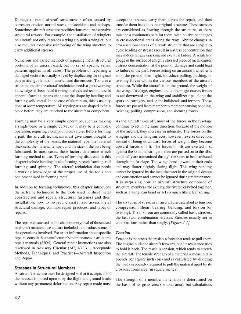
Figure 4-3. Scales.
1 2 3 4 5 6 7 8 9
1 2 3 4 6 7 8 9
8 16 24 32 40 48 56
4 8 12 16 20 24 2828 4
56 8
191 2 3 4 5 6 7 8 9
4 8 12 16 20 24 284 8 12 16 20 24 28 4 8 12 16 20 24 28
8 16 24 32 40 48 568 16 24 32 40 48 56 8 16 24 32 40 48 56
1 2 3 4 5 6 7 8 9 1 2 3 4 5 6 7 8 9
1 2 3 4 6 7 8 95
1 2 3 4 6 7 8 95
1 2 3 4 6 7 8 95
9 15
10 THS
100 THS
32 MOS
64 THS
3
32
1 2 5
541
1 2 3 4 5
4
8 THS
16 THS
reference axis at right angles to these planes. This action may be illustrated by a rod fixed solidly at one end and twisted by a weight placed on a lever arm at the other, producing the equivalent of two equal and opposite forces acting on the rod at some distance from each other. A shearing action is set up all along the rod, with the center line of the rod representing the neutral axis.
Bending Bending (or beam stress) is a combination of compression and tension. The rod in Figure 4-1E has been shortened (compressed) on the inside of the bend and stretched on the outside of the bend. Note that the bending stress causes a tensile stress to act on the upper half of the beam and a compressive stress on the lower half. These stresses act in opposition on the two sides of the center line of the member, which is called the neutral axis. Since these forces acting in opposite directions are next to each other at the neutral axis, the greatest shear stress occurs along this line, and none exists at the extreme upper or lower surfaces of the beam.
Tools for Sheet Metal Construction and RepairWithout modern metalworking tools and machines, the job of the airframe technician would be more difficult and tiresome, and the time required to finish a task would be much greater. These specialized tools and machines help the airframe technician construct or repair sheet metal in a faster, simpler, and better manner than possible in the past. Powered by human muscle, electricity, or compressed air, these tools are used to lay out, mark, cut, sand, or drill sheet metal.
Layout ToolsBefore fitting repair parts into an aircraft structure, the new sections must be measured and marked, or laid out to the dimensions needed to make the repair part. Tools utilized for this process are discussed in this section.
ScalesScales are available in various lengths, with the 6-inch and 12-inch scales being the most common and affordable. A scale with fractions on one side and decimals on the other side is very useful. To obtain an accurate measurement, measure with the scale held on edge from the 1-inch mark instead of the end. Use the graduation marks on the side to set a divider or compass. [Figure 4-3]
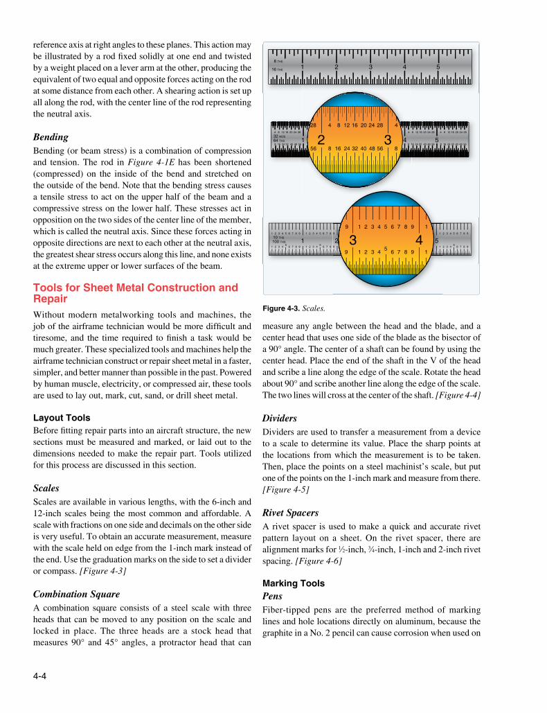
Combination SquareA combination square consists of a steel scale with three heads that can be moved to any position on the scale and locked in place. The three heads are a stock head that measures 90° and 45° angles, a protractor head that can
measure any angle between the head and the blade, and a center head that uses one side of the blade as the bisector of a 90° angle. The center of a shaft can be found by using the center head. Place the end of the shaft in the V of the head and scribe a line along the edge of the scale. Rotate the head about 90° and scribe another line along the edge of the scale. The two lines will cross at the center of the shaft. [Figure 4-4]
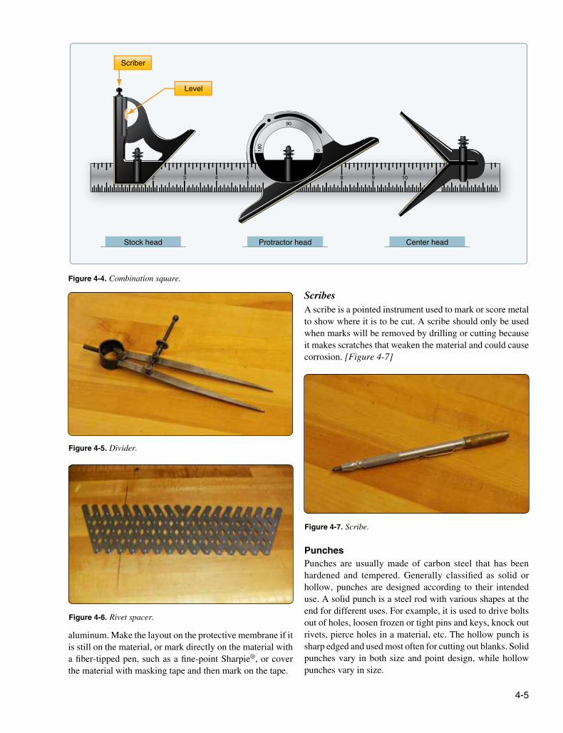
DividersDividers are used to transfer a measurement from a device to a scale to determine its value. Place the sharp points at the locations from which the measurement is to be taken. Then, place the points on a steel machinist’s scale, but put one of the points on the 1-inch mark and measure from there. [Figure 4-5]
Rivet SpacersA rivet spacer is used to make a quick and accurate rivet pattern layout on a sheet. On the rivet spacer, there are alignment marks for 1⁄2-inch, 3⁄4-inch, 1-inch and 2-inch rivet spacing. [Figure 4-6]
Marking ToolsPensFiber-tipped pens are the preferred method of marking lines and hole locations directly on aluminum, because the graphite in a No. 2 pencil can cause corrosion when used on
4-5
Figure 4-4. Combination square.
112
0180
90
3 4 5 8 9 10
Scriber
Level
Stock head Protractor head Center head
Figure 4-5. Divider.
Figure 4-6. Rivet spacer.
Figure 4-7. Scribe.
aluminum. Make the layout on the protective membrane if it is still on the material, or mark directly on the material with a fiber-tipped pen, such as a fine-point Sharpie®, or cover the material with masking tape and then mark on the tape.
ScribesA scribe is a pointed instrument used to mark or score metal to show where it is to be cut. A scribe should only be used when marks will be removed by drilling or cutting because it makes scratches that weaken the material and could cause corrosion. [Figure 4-7]
PunchesPunches are usually made of carbon steel that has been hardened and tempered. Generally classified as solid or hollow, punches are designed according to their intended use. A solid punch is a steel rod with various shapes at the end for different uses. For example, it is used to drive bolts out of holes, loosen frozen or tight pins and keys, knock out rivets, pierce holes in a material, etc. The hollow punch is sharp edged and used most often for cutting out blanks. Solid punches vary in both size and point design, while hollow punches vary in size.
4-6
Figure 4-8. Prick punch.
Figure 4-9. Center punch.
Figure 4-10. Automatic center punch.
Figure 4-11. Transfer punch.
Transfer punch
Use old skin as template
New skin
Prick PunchA prick punch is primarily used during layout to place reference marks on metal because it produces a small indentation. [Figure 4-8] After layout is finished, the indentation is enlarged with a center punch to allow for drilling. The prick punch can also be used to transfer dimensions from a paper pattern directly onto the metal. Take the following precautions when using a prick punch:
• Never strike a prick punch a heavy blow with a hammer because it could bend the punch or cause excessive damage to the item being worked.
• Do not use a prick punch to remove objects from holes because the point of the punch spreads the object and causes it to bind even more.
Center PunchA center punch is used to make indentations in metal as an aid in drilling. [Figure 4-9] These indentations help the drill, which has a tendency to wander on a flat surface, stay on the mark as it goes through the metal. The traditional center punch is used with a hammer, has a heavier body than the prick punch, and has a point ground to an angle of about 60°. Take the following precautions when using a center punch:
• Never strike the center punch with enough force to dimple the item around the indentation or cause the metal to protrude through the other side of the sheet.
• Do not use a center punch to remove objects from holes because the point of the punch spreads the object and causes it to bind even more.
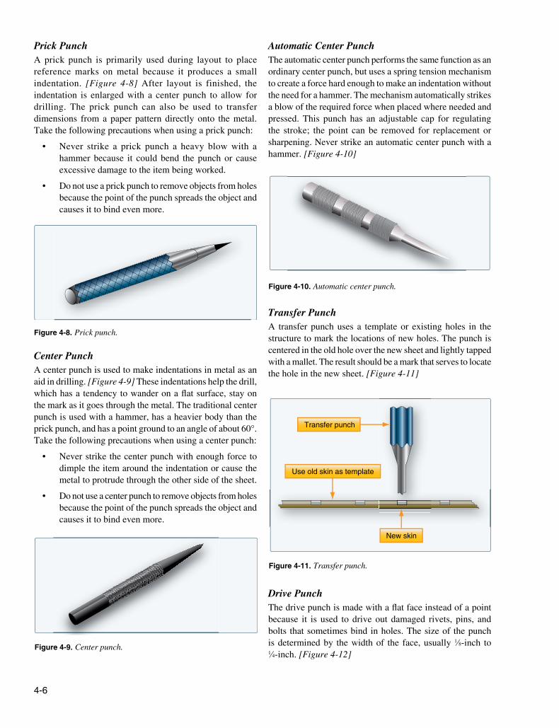
Automatic Center PunchThe automatic center punch performs the same function as an ordinary center punch, but uses a spring tension mechanism to create a force hard enough to make an indentation without the need for a hammer. The mechanism automatically strikes a blow of the required force when placed where needed and pressed. This punch has an adjustable cap for regulating the stroke; the point can be removed for replacement or sharpening. Never strike an automatic center punch with a hammer. [Figure 4-10]
Transfer PunchA transfer punch uses a template or existing holes in the structure to mark the locations of new holes. The punch is centered in the old hole over the new sheet and lightly tapped with a mallet. The result should be a mark that serves to locate the hole in the new sheet. [Figure 4-11]
Drive PunchThe drive punch is made with a flat face instead of a point because it is used to drive out damaged rivets, pins, and bolts that sometimes bind in holes. The size of the punch is determined by the width of the face, usually 1⁄8-inch to 1⁄4-inch. [Figure 4-12]
4-7
Figure 4-13. Pin punch.
Figure 4-12. Drive punch.
Figure 4-14. Chassis punch.
Figure 4-15. Awl.
Figure 4-16. Awl usage.
4
5
6
1
2
3
7
8
9
10
11
12
Pin PunchThe pin punch typically has a straight shank characterized by a hexagonal body. Pin punch points are sized in 1⁄32-inch increments of an inch and range from 1⁄16-inch to 3⁄8-inch in diameter. The usual method for driving out a pin or bolt is to start working it out with a drive punch until the shank of the punch is touching the sides of the hole. Then use a pin punch to drive the pin or bolt the rest of the way out of the hole. [Figure 4-13]
Chassis PunchA chassis punch is used to make holes in sheet metal parts for the installation of instruments and other avionics appliance, as well as lightening holes in ribs and spars. Sized in 1⁄16 of an inch, they are available in sizes from 1⁄2 inch to 3 inches. [Figure 4-14]
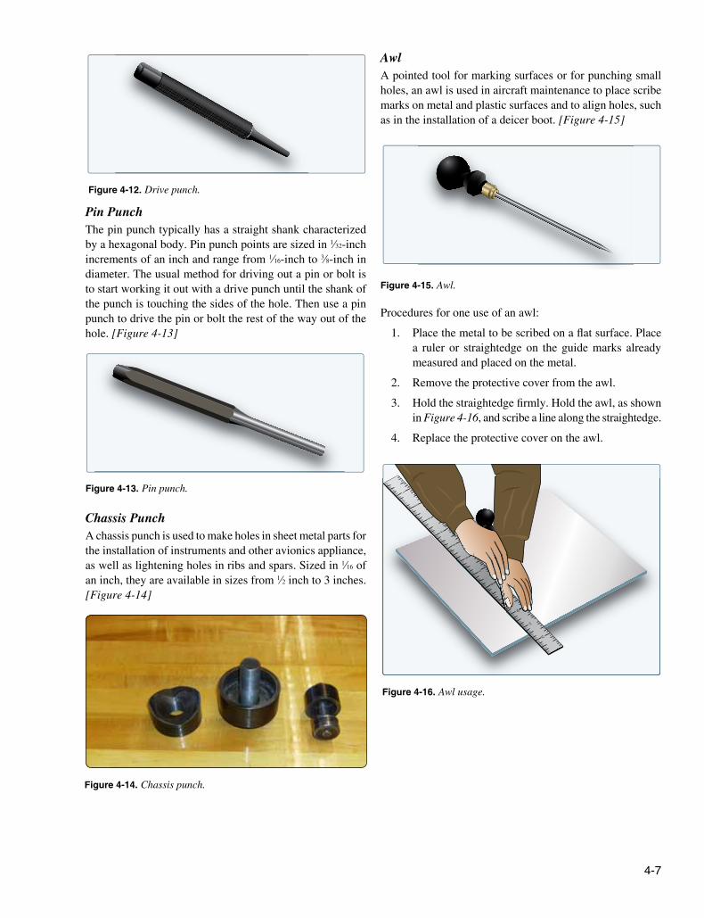
AwlA pointed tool for marking surfaces or for punching small holes, an awl is used in aircraft maintenance to place scribe marks on metal and plastic surfaces and to align holes, such as in the installation of a deicer boot. [Figure 4-15]
Procedures for one use of an awl:
1. Place the metal to be scribed on a flat surface. Place a ruler or straightedge on the guide marks already measured and placed on the metal.
2. Remove the protective cover from the awl.
3. Hold the straightedge firmly. Hold the awl, as shown in Figure 4-16, and scribe a line along the straightedge.
4. Replace the protective cover on the awl.

4-8
Figure 4-17. Hole duplicator.
New skin
Old skin
Angle
Figure 4-18. Kett saw.
Figure 4-19. Pneumatic circular saw.
Hole DuplicatorAvailable in a variety of sizes and styles, hole duplicators, or hole finders, utilize the old covering as a template to locate and match existing holes in the structure. Holes in a replacement sheet or in a patch must be drilled to match existing holes in the structure and the hole duplicator simplifies this process. Figure 4-17 illustrates one type of hole duplicator. The peg on the bottom leg of the duplicator fits into the existing rivet hole. To make the hole in the replacement sheet or patch, drill through the bushing on the top leg. If the duplicator is properly made, holes drilled in this manner are in perfect alignment. A separate duplicator must be used for each diameter of rivet.
Cutting ToolsPowered and nonpowered metal cutting tools available to the aviation technician include various types of saws, nibblers, shears, sanders, notchers, and grinders.
Circular-Cutting SawsThe circular cutting saw cuts with a toothed, steel disk that rotates at high speed. Handheld or table mounted and powered by compressed air, this power saw cuts metal or wood. To prevent the saw from grabbing the metal, keep a firm grip on the saw handle at all times. Check the blade carefully for cracks prior to installation because a cracked blade can fly apart during use, possibly causing serious injury.
Kett Saw The Kett saw is an electrically operated, portable circular cutting saw that uses blades of various diameters. [Figure 4-18] Since the head of this saw can be turned to any desired angle, it is useful for removing damaged sections on a stringer. The advantages of a Kett saw include:
1. Can cut metal up to 3⁄16-inch in thickness.
2. No starting hole is required.
3. A cut can be started anywhere on a sheet of metal.
4. Can cut an inside or outside radius.
Pneumatic Circular Cutting SawThe pneumatic circular cutting saw, useful for cutting out damage, is similar to the Kett saw. [Figure 4-19]