Embed Size (px)
Citation preview
International Journal of Academic Engineering Research (IJAER) ISSN: 2643-9085
Vol. 3 Issue 6, June – 2019, Pages: 12-24
www.ijeais.org/ijaer
12
The Conventional Spinning and Flow Forming Essam K. Saied; Ayman A. Abd-Eltwab; M. N. El-sheikh
Department of Mechanical Engineering Beni-Suef University
Beni-Suef, EGYPT
S. Z. El-Abden; M. Abdel-Rahman
Department of Mechanical Engineering
Minia University
Minia, EGYPT
Ibrahim M. Hassab-Allah
Department of Mechanical Engineering
Assiut University
Assiut, EGYPT
Abstract: The thin wall cup products are largely used in industries, it is usually made by a conventional spinning process to produce the cup shape, followed by wall thickness reduction process (Flow Forming) to reduce the cup wall thickness. There is no
one process can perform a thin wall cup in one stroke. The deep drawing process with ironing at the same stroke is now being
investigated in some literatures, but it still cannot reduce the wall thickness up to 50 or 70%. This article is aiming to investigate
the conventional spinning process and the flow forming process; how these two processes conducted and the development in the
two processes. A review of the two processes is included in this article. After that; suggestions for future work in the two processes
and to conduct the two processes together are prescribed.
Keywords—Conventional spinning, Flow forming, Thin wall cup
1. INTRODUCTION
Production process is mainly a compound activity, concerned with people who have a broad number of disciplines and skills and a widespread kind of equipment, tools, and utensils with several levels of computerization, such as CPUs, robots, and other equipment. Manufacturing searches must be accessible to several requirements and progress [1]. The metal forming is an important branch of the manufacturing processes, this is due to its ability of manufacturing a part without any metal loss. Many types of metal forming are available now, but the spinning process is the concerned subdivision of the forming processes.
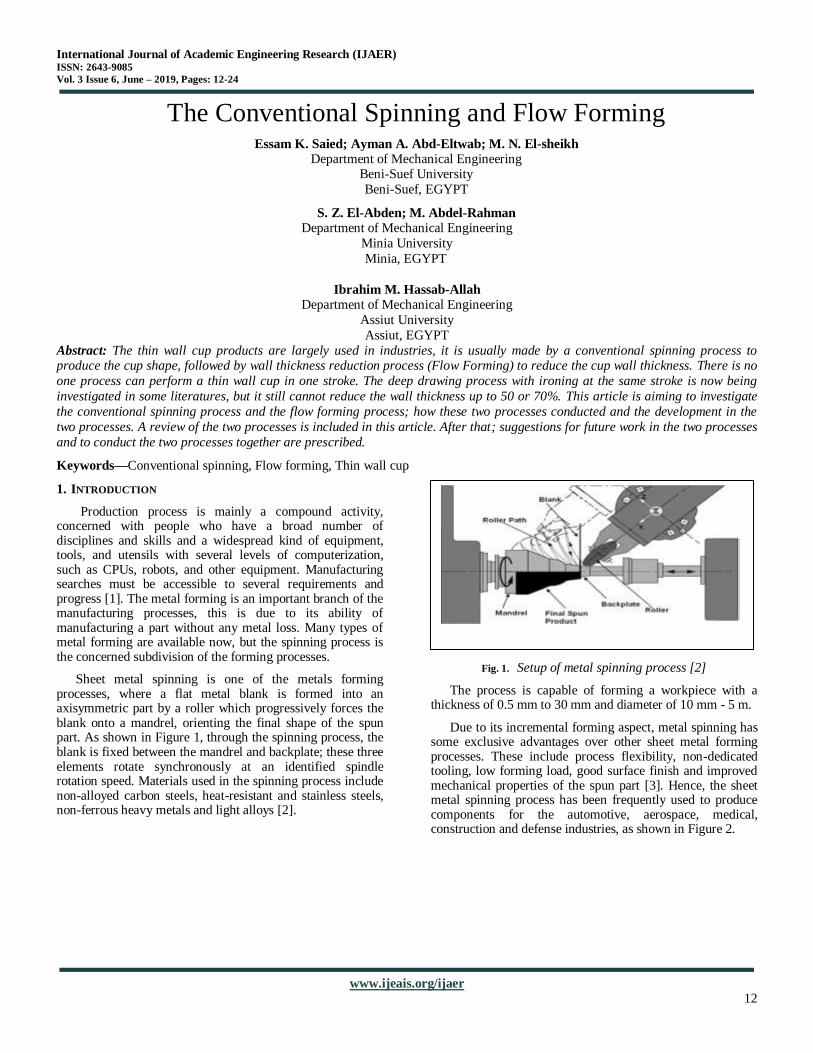
Sheet metal spinning is one of the metals forming processes, where a flat metal blank is formed into an axisymmetric part by a roller which progressively forces the blank onto a mandrel, orienting the final shape of the spun part. As shown in Figure 1, through the spinning process, the blank is fixed between the mandrel and backplate; these three elements rotate synchronously at an identified spindle rotation speed. Materials used in the spinning process include non-alloyed carbon steels, heat-resistant and stainless steels, non-ferrous heavy metals and light alloys [2].
Fig. 1. Setup of metal spinning process [2]
The process is capable of forming a workpiece with a thickness of 0.5 mm to 30 mm and diameter of 10 mm - 5 m.
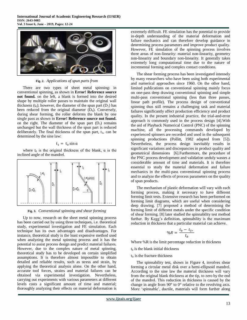
Due to its incremental forming aspect, metal spinning has some exclusive advantages over other sheet metal forming processes. These include process flexibility, non-dedicated tooling, low forming load, good surface finish and improved mechanical properties of the spun part [3]. Hence, the sheet metal spinning process has been frequently used to produce components for the automotive, aerospace, medical, construction and defense industries, as shown in Figure 2.
International Journal of Academic Engineering Research (IJAER) ISSN: 2643-9085
Vol. 3 Issue 6, June – 2019, Pages: 12-24
www.ijeais.org/ijaer
13
Fig. 2. Applications of spun parts from
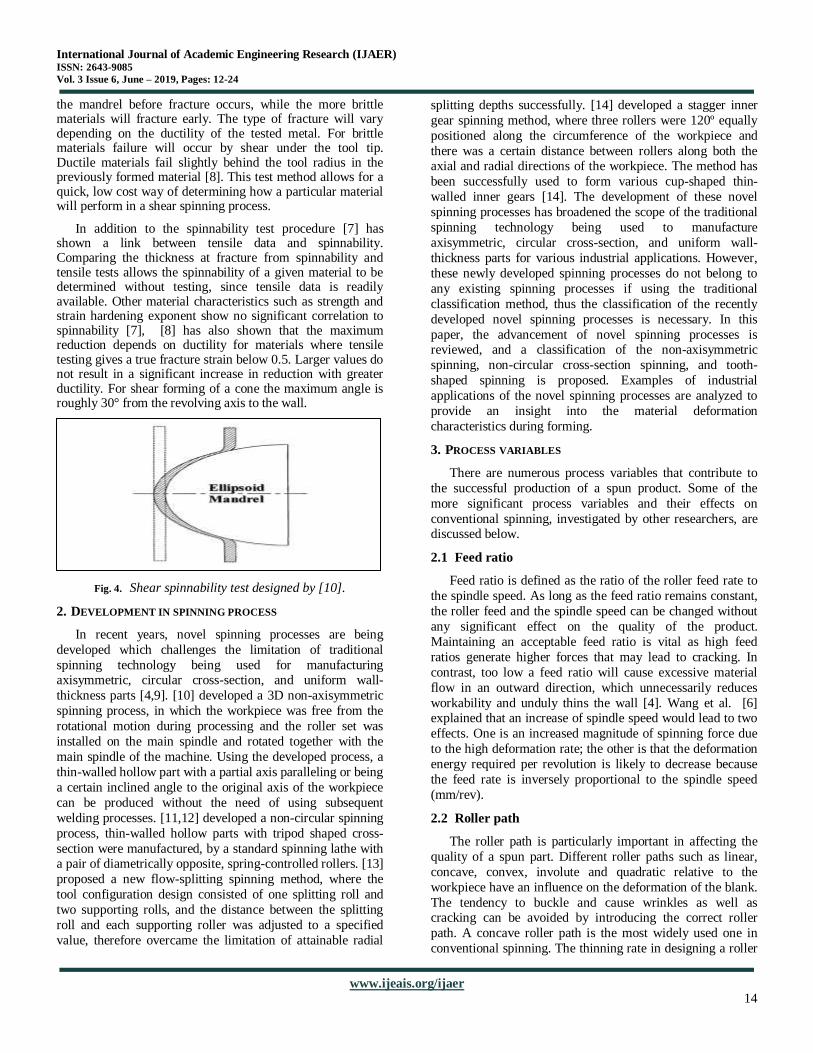
There are two types of sheet metal spinning: in conventional spinning, as shown in Error! Reference source not found. on the left, a blank is formed into the desired shape by multiple roller passes to maintain the original wall thickness (t0); however, the diameter of the spun part (D1) has been reduced from the original diameter (D0). Conversely, during shear forming, the roller deforms the blank by one single pass as shown in Error! Reference source not found. on the right. The diameter of the spun part (D1) remains unchanged but the wall thickness of the spun part is reduced deliberately. The final thickness of the spun part, t1, can be determined by the sine law:
where t0 is the original thickness of the blank, α is the inclined angle of the mandrel.
Fig. 3. Conventional spinning and shear forming
Up to now, research on the sheet metal spinning process has been carried out by using three techniques, i.e. theoretical study, experimental investigation and FE simulation. Each technique has its own advantages and disadvantages. For instance, theoretical study is the least expensive method used when analyzing the metal spinning process and it has the potential to assist process design and predict material failures. However, due to the complex nature of metal spinning, theoretical study has to be developed on certain simplified assumptions. It is therefore almost impossible to obtain detailed and reliable results, such as stress and strain, by applying the theoretical analysis alone. On the other hand, accurate tool forces, strains and material failures can be obtained via experimental investigation. Nevertheless, carrying out experiments with various parameters at different levels costs a significant amount of time and material; thoroughly analyzing their effects on material deformation is
extremely difficult. FE simulation has the potential to provide in-depth understanding of the material deformation and failure mechanics and can therefore develop guidance in determining process parameters and improve product quality. However, FE simulation of the spinning process involves three areas of non-linearity: material non-linearity, geometry non-linearity and boundary non-linearity. It generally takes extremely long computational time due to the nature of incremental forming and complex contact conditions.
The shear forming process has been investigated intensely
by many researchers who have been using both experimental
and numerical approaches since 1960. On the other hand,
limited publications on conventional spinning mainly focus
on one-pass deep drawing conventional spinning and simple
multi-pass conventional spinning (less than three passes,
linear path profile). The process design of conventional
spinning thus still remains a challenging task and material
failures significantly affect production efficiency and product
quality. In the present industrial practice, the trial-and-error
approach is commonly used in the process design [4].With
the aid of Playback Numerical Control (PNC) of the spinning machine, all the processing commands developed by
experienced spinners are recorded and used in the subsequent
spinning productions (Pollitt, 1982 adapted from [5]).
Nevertheless, the process design inevitably results in
significant variations and discrepancies in product quality and
geometrical dimensions [6].Furthermore, the procedure of
the PNC process development and validation unduly wastes a
considerable amount of time and materials. It is therefore
essential to study the material deformation and failure
mechanics in the multi-pass conventional spinning process
and to analyze the effects of process parameters on the quality of spun products.
The mechanism of plastic deformation will vary with each forming process, making it necessary to have different forming limit tests. Extensive research has been performed on forming limit diagrams, which are useful when considering deep drawing. [7] proposed a method of determining the forming limit of different metals under the specific condition of shear forming. [8] later studied the spinnability test method further. By Kegg’s definition, spinnability is the maximum reduction in thickness that a particular material can achieve.
Where %R is the limit percentage reduction in thickness
tb is the blank initial thickness
tfr is the fracture thickness
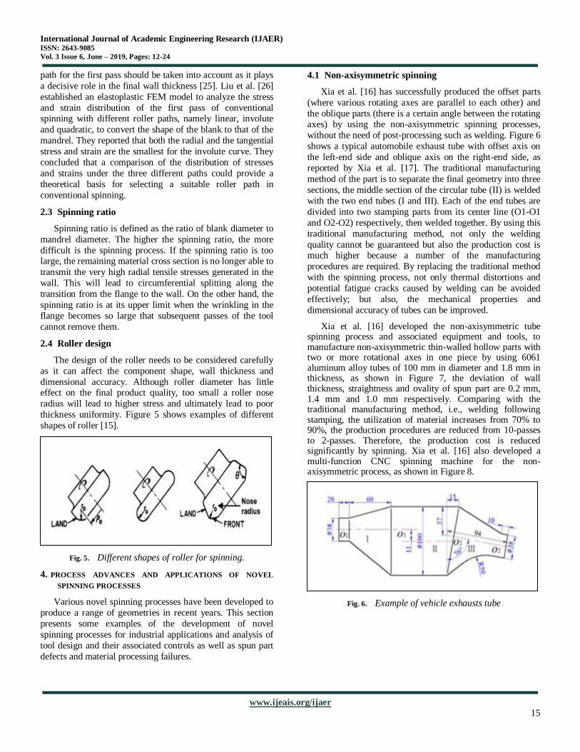
The spinnability test, shown in Figure 4, involves shear forming a circular metal disk over a hemi-ellipsoid mandrel. According to the sine law the material thickness will vary from the original blank thickness at the tip, to zero by the end of the mandrel. This reduction in thickness is caused by the change in angle from 90° to 0° relative to the revolving axis. More ‘spinnable’, ductile, materials will form further along
International Journal of Academic Engineering Research (IJAER) ISSN: 2643-9085
Vol. 3 Issue 6, June – 2019, Pages: 12-24
www.ijeais.org/ijaer
14
the mandrel before fracture occurs, while the more brittle materials will fracture early. The type of fracture will vary depending on the ductility of the tested metal. For brittle materials failure will occur by shear under the tool tip. Ductile materials fail slightly behind the tool radius in the previously formed material [8]. This test method allows for a quick, low cost way of determining how a particular material will perform in a shear spinning process.
In addition to the spinnability test procedure [7] has shown a link between tensile data and spinnability. Comparing the thickness at fracture from spinnability and tensile tests allows the spinnability of a given material to be determined without testing, since tensile data is readily available. Other material characteristics such as strength and strain hardening exponent show no significant correlation to spinnability [7], [8] has also shown that the maximum reduction depends on ductility for materials where tensile testing gives a true fracture strain below 0.5. Larger values do not result in a significant increase in reduction with greater ductility. For shear forming of a cone the maximum angle is roughly 30° from the revolving axis to the wall.
Fig. 4. Shear spinnability test designed by [10].
2. DEVELOPMENT IN SPINNING PROCESS
In recent years, novel spinning processes are being
developed which challenges the limitation of traditional
spinning technology being used for manufacturing axisymmetric, circular cross-section, and uniform wall-
thickness parts [4,9]. [10] developed a 3D non-axisymmetric
spinning process, in which the workpiece was free from the
rotational motion during processing and the roller set was
installed on the main spindle and rotated together with the
main spindle of the machine. Using the developed process, a
thin-walled hollow part with a partial axis paralleling or being
a certain inclined angle to the original axis of the workpiece
can be produced without the need of using subsequent
welding processes. [11,12] developed a non-circular spinning
process, thin-walled hollow parts with tripod shaped cross-
section were manufactured, by a standard spinning lathe with a pair of diametrically opposite, spring-controlled rollers. [13]
proposed a new flow-splitting spinning method, where the
tool configuration design consisted of one splitting roll and
two supporting rolls, and the distance between the splitting
roll and each supporting roller was adjusted to a specified
value, therefore overcame the limitation of attainable radial
splitting depths successfully. [14] developed a stagger inner
gear spinning method, where three rollers were 120º equally
positioned along the circumference of the workpiece and
there was a certain distance between rollers along both the axial and radial directions of the workpiece. The method has
been successfully used to form various cup-shaped thin-
walled inner gears [14]. The development of these novel
spinning processes has broadened the scope of the traditional
spinning technology being used to manufacture
axisymmetric, circular cross-section, and uniform wall-
thickness parts for various industrial applications. However,
these newly developed spinning processes do not belong to
any existing spinning processes if using the traditional
classification method, thus the classification of the recently
developed novel spinning processes is necessary. In this
paper, the advancement of novel spinning processes is reviewed, and a classification of the non-axisymmetric
spinning, non-circular cross-section spinning, and tooth-
shaped spinning is proposed. Examples of industrial
applications of the novel spinning processes are analyzed to
provide an insight into the material deformation
characteristics during forming.
3. PROCESS VARIABLES
There are numerous process variables that contribute to
the successful production of a spun product. Some of the
more significant process variables and their effects on
conventional spinning, investigated by other researchers, are discussed below.
2.1 Feed ratio
Feed ratio is defined as the ratio of the roller feed rate to
the spindle speed. As long as the feed ratio remains constant,
the roller feed and the spindle speed can be changed without
any significant effect on the quality of the product.
Maintaining an acceptable feed ratio is vital as high feed
ratios generate higher forces that may lead to cracking. In
contrast, too low a feed ratio will cause excessive material
flow in an outward direction, which unnecessarily reduces
workability and unduly thins the wall [4]. Wang et al. [6] explained that an increase of spindle speed would lead to two
effects. One is an increased magnitude of spinning force due
to the high deformation rate; the other is that the deformation
energy required per revolution is likely to decrease because
the feed rate is inversely proportional to the spindle speed
(mm/rev).
2.2 Roller path
The roller path is particularly important in affecting the
quality of a spun part. Different roller paths such as linear,
concave, convex, involute and quadratic relative to the
workpiece have an influence on the deformation of the blank.
The tendency to buckle and cause wrinkles as well as cracking can be avoided by introducing the correct roller
path. A concave roller path is the most widely used one in
conventional spinning. The thinning rate in designing a roller
International Journal of Academic Engineering Research (IJAER) ISSN: 2643-9085
Vol. 3 Issue 6, June – 2019, Pages: 12-24
www.ijeais.org/ijaer
15
path for the first pass should be taken into account as it plays
a decisive role in the final wall thickness [25]. Liu et al. [26]
established an elastoplastic FEM model to analyze the stress
and strain distribution of the first pass of conventional spinning with different roller paths, namely linear, involute
and quadratic, to convert the shape of the blank to that of the
mandrel. They reported that both the radial and the tangential
stress and strain are the smallest for the involute curve. They
concluded that a comparison of the distribution of stresses
and strains under the three different paths could provide a
theoretical basis for selecting a suitable roller path in
conventional spinning.
2.3 Spinning ratio
Spinning ratio is defined as the ratio of blank diameter to
mandrel diameter. The higher the spinning ratio, the more
difficult is the spinning process. If the spinning ratio is too large, the remaining material cross section is no longer able to
transmit the very high radial tensile stresses generated in the
wall. This will lead to circumferential splitting along the
transition from the flange to the wall. On the other hand, the
spinning ratio is at its upper limit when the wrinkling in the
flange becomes so large that subsequent passes of the tool
cannot remove them.
2.4 Roller design
The design of the roller needs to be considered carefully
as it can affect the component shape, wall thickness and
dimensional accuracy. Although roller diameter has little effect on the final product quality, too small a roller nose
radius will lead to higher stress and ultimately lead to poor
thickness uniformity. Figure 5 shows examples of different
shapes of roller [15].
Fig. 5. Different shapes of roller for spinning.
4. PROCESS ADVANCES AND APPLICATIONS OF NOVEL
SPINNING PROCESSES
Various novel spinning processes have been developed to
produce a range of geometries in recent years. This section
presents some examples of the development of novel
spinning processes for industrial applications and analysis of
tool design and their associated controls as well as spun part
defects and material processing failures.
4.1 Non-axisymmetric spinning
Xia et al. [16] has successfully produced the offset parts
(where various rotating axes are parallel to each other) and
the oblique parts (there is a certain angle between the rotating axes) by using the non-axisymmetric spinning processes,
without the need of post-processing such as welding. Figure 6
shows a typical automobile exhaust tube with offset axis on
the left-end side and oblique axis on the right-end side, as
reported by Xia et al. [17]. The traditional manufacturing
method of the part is to separate the final geometry into three
sections, the middle section of the circular tube (II) is welded
with the two end tubes (I and III). Each of the end tubes are
divided into two stamping parts from its center line (O1-O1
and O2-O2) respectively, then welded together. By using this
traditional manufacturing method, not only the welding
quality cannot be guaranteed but also the production cost is much higher because a number of the manufacturing
procedures are required. By replacing the traditional method
with the spinning process, not only thermal distortions and
potential fatigue cracks caused by welding can be avoided
effectively; but also, the mechanical properties and
dimensional accuracy of tubes can be improved.
Xia et al. [16] developed the non-axisymmetric tube spinning process and associated equipment and tools, to manufacture non-axisymmetric thin-walled hollow parts with two or more rotational axes in one piece by using 6061 aluminum alloy tubes of 100 mm in diameter and 1.8 mm in thickness, as shown in Figure 7, the deviation of wall thickness, straightness and ovality of spun part are 0.2 mm, 1.4 mm and 1.0 mm respectively. Comparing with the traditional manufacturing method, i.e., welding following stamping, the utilization of material increases from 70% to 90%, the production procedures are reduced from 10-passes to 2-passes. Therefore, the production cost is reduced significantly by spinning. Xia et al. [16] also developed a multi-function CNC spinning machine for the non-axisymmetric process, as shown in Figure 8.
Fig. 6. Example of vehicle exhausts tube
International Journal of Academic Engineering Research (IJAER) ISSN: 2643-9085
Vol. 3 Issue 6, June – 2019, Pages: 12-24
www.ijeais.org/ijaer
16
Fig. 7. Non-axisymmetric spun parts [35].
Fig. 8. HGPX-WSM multi-function CNC spinning machine
[24]
4.2 Non-circular cross-section spinning
Amano and Tamura reported a non-circular spinning
method by using a radially offset roller on a modified
spinning lathe to produce the hollow parts with elliptical
cross-section [18]. Gao et al. developed another mechanical
setup in which the spindle axis coincident with the revolution
was offset [19]. In the experiment, the aluminum sheet of 1 mm in thicknesses is used as the blank. Figure 9 shows the
spinning device and the spun workpieces of elliptical cross-
section with φ110 mm in long axis and φ 90 mm in short axis.
As can be seen in Error! Reference source not found.(a),
the transmission shaft is installed on the holding chuck of a
lathe at one end, while the holster is fixed onto the slideway
of the lathe. Two slide blocks are fixed onto the revolving
drum. The three-jaw chuck is installed on the rotor disc, on
which two orthogonal sliding chutes are attached. The slide
blocks and the block mounted at the end of the shaft extend
into the two sliding chutes and can slide along them. Therefore, the rotor disc and the revolving drum can be
rotated by the lathe through the transmission shaft. The sheet
blank is fixed onto the end surface of the mandrel by a
supporting tail. The roller is installed in a small tool carrier of
the lathe, so that the path of the roller can be controlled by the
motion of the tool carrier. By changing the path of the roller,
the spinning of parts with different elliptical shapes can be
realized, and the maximum wall-thickness thinning ratio of
spun workpiece is 16% [19].
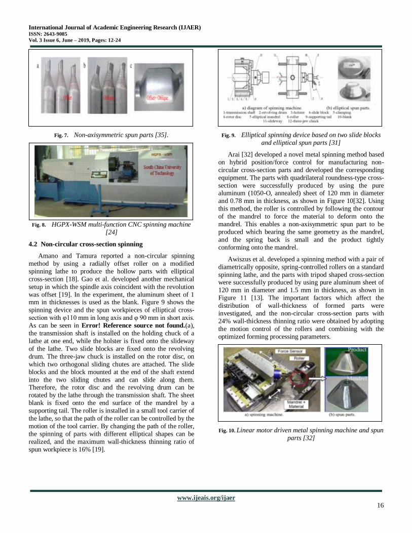
Fig. 9. Elliptical spinning device based on two slide blocks
and elliptical spun parts [31]
Arai [32] developed a novel metal spinning method based
on hybrid position/force control for manufacturing non-
circular cross-section parts and developed the corresponding
equipment. The parts with quadrilateral roundness-type cross-
section were successfully produced by using the pure aluminum (1050-O, annealed) sheet of 120 mm in diameter
and 0.78 mm in thickness, as shown in Figure 10[32]. Using
this method, the roller is controlled by following the contour
of the mandrel to force the material to deform onto the
mandrel. This enables a non-axisymmetric spun part to be
produced which bearing the same geometry as the mandrel,
and the spring back is small and the product tightly
conforming onto the mandrel.
Awiszus et al. developed a spinning method with a pair of
diametrically opposite, spring-controlled rollers on a standard
spinning lathe, and the parts with tripod shaped cross-section were successfully produced by using pure aluminum sheet of
120 mm in diameter and 1.5 mm in thickness, as shown in
Figure 11 [13]. The important factors which affect the
distribution of wall-thickness of formed parts were
investigated, and the non-circular cross-section parts with
24% wall-thickness thinning ratio were obtained by adopting
the motion control of the rollers and combining with the
optimized forming processing parameters.
Fig. 10. Linear motor driven metal spinning machine and spun
parts [32]
International Journal of Academic Engineering Research (IJAER) ISSN: 2643-9085
Vol. 3 Issue 6, June – 2019, Pages: 12-24
www.ijeais.org/ijaer
17
Fig. 11. Tripod shaped spinning device and spun parts [13]
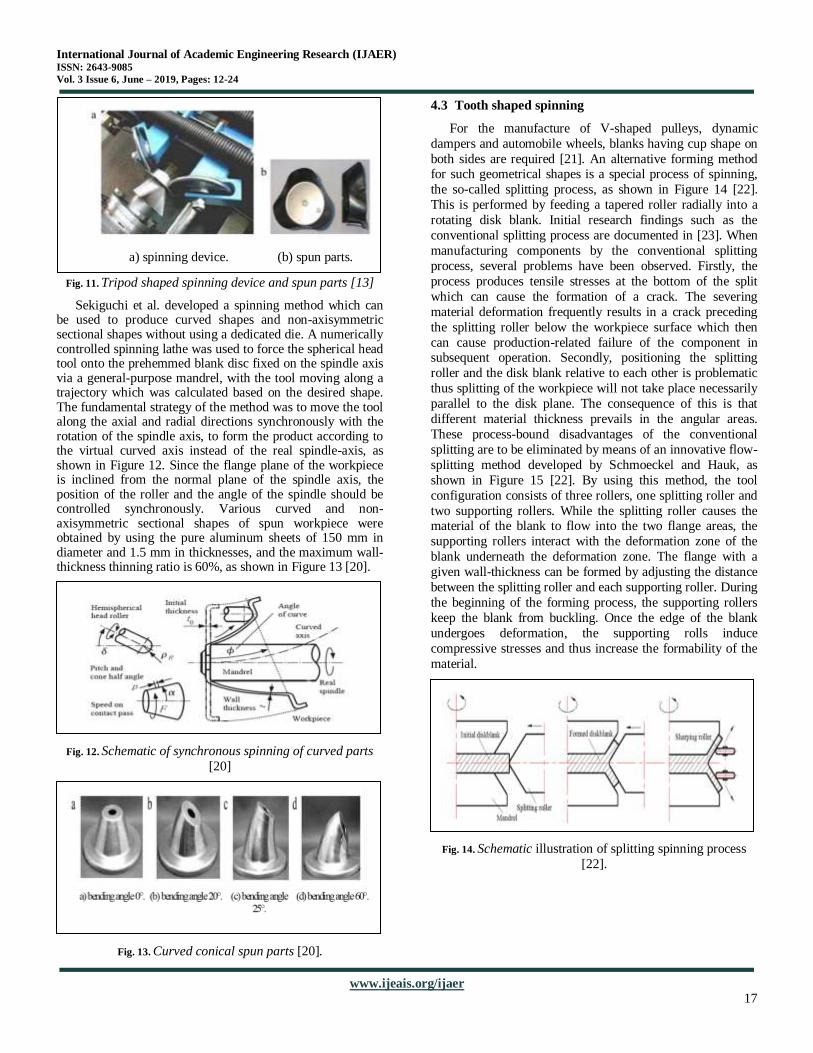
Sekiguchi et al. developed a spinning method which can be used to produce curved shapes and non-axisymmetric sectional shapes without using a dedicated die. A numerically controlled spinning lathe was used to force the spherical head tool onto the prehemmed blank disc fixed on the spindle axis via a general-purpose mandrel, with the tool moving along a trajectory which was calculated based on the desired shape. The fundamental strategy of the method was to move the tool along the axial and radial directions synchronously with the rotation of the spindle axis, to form the product according to the virtual curved axis instead of the real spindle-axis, as shown in Figure 12. Since the flange plane of the workpiece is inclined from the normal plane of the spindle axis, the position of the roller and the angle of the spindle should be controlled synchronously. Various curved and non-axisymmetric sectional shapes of spun workpiece were obtained by using the pure aluminum sheets of 150 mm in diameter and 1.5 mm in thicknesses, and the maximum wall-thickness thinning ratio is 60%, as shown in Figure 13 [20].
Fig. 12. Schematic of synchronous spinning of curved parts
[20]
Fig. 13. Curved conical spun parts [20].
4.3 Tooth shaped spinning
For the manufacture of V-shaped pulleys, dynamic
dampers and automobile wheels, blanks having cup shape on
both sides are required [21]. An alternative forming method for such geometrical shapes is a special process of spinning,
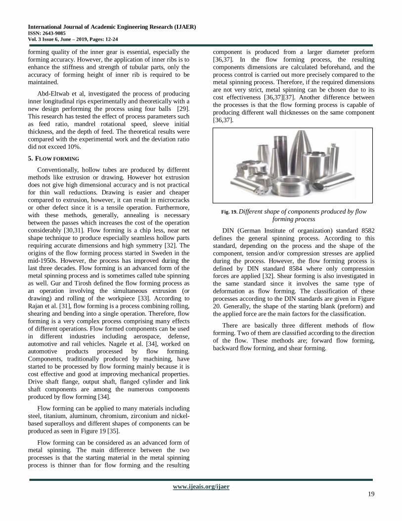
the so-called splitting process, as shown in Figure 14 [22].
This is performed by feeding a tapered roller radially into a
rotating disk blank. Initial research findings such as the
conventional splitting process are documented in [23]. When
manufacturing components by the conventional splitting
process, several problems have been observed. Firstly, the
process produces tensile stresses at the bottom of the split
which can cause the formation of a crack. The severing
material deformation frequently results in a crack preceding
the splitting roller below the workpiece surface which then
can cause production-related failure of the component in subsequent operation. Secondly, positioning the splitting
roller and the disk blank relative to each other is problematic
thus splitting of the workpiece will not take place necessarily
parallel to the disk plane. The consequence of this is that
different material thickness prevails in the angular areas.
These process-bound disadvantages of the conventional
splitting are to be eliminated by means of an innovative flow-
splitting method developed by Schmoeckel and Hauk, as
shown in Figure 15 [22]. By using this method, the tool
configuration consists of three rollers, one splitting roller and
two supporting rollers. While the splitting roller causes the material of the blank to flow into the two flange areas, the
supporting rollers interact with the deformation zone of the
blank underneath the deformation zone. The flange with a
given wall-thickness can be formed by adjusting the distance
between the splitting roller and each supporting roller. During
the beginning of the forming process, the supporting rollers
keep the blank from buckling. Once the edge of the blank
undergoes deformation, the supporting rolls induce
compressive stresses and thus increase the formability of the
material.
Fig. 14. Schematic illustration of splitting spinning process
[22].
a) spinning device. (b) spun parts.
International Journal of Academic Engineering Research (IJAER) ISSN: 2643-9085
Vol. 3 Issue 6, June – 2019, Pages: 12-24
www.ijeais.org/ijaer
18
Fig. 15. Split spinning forming device and parts [13].
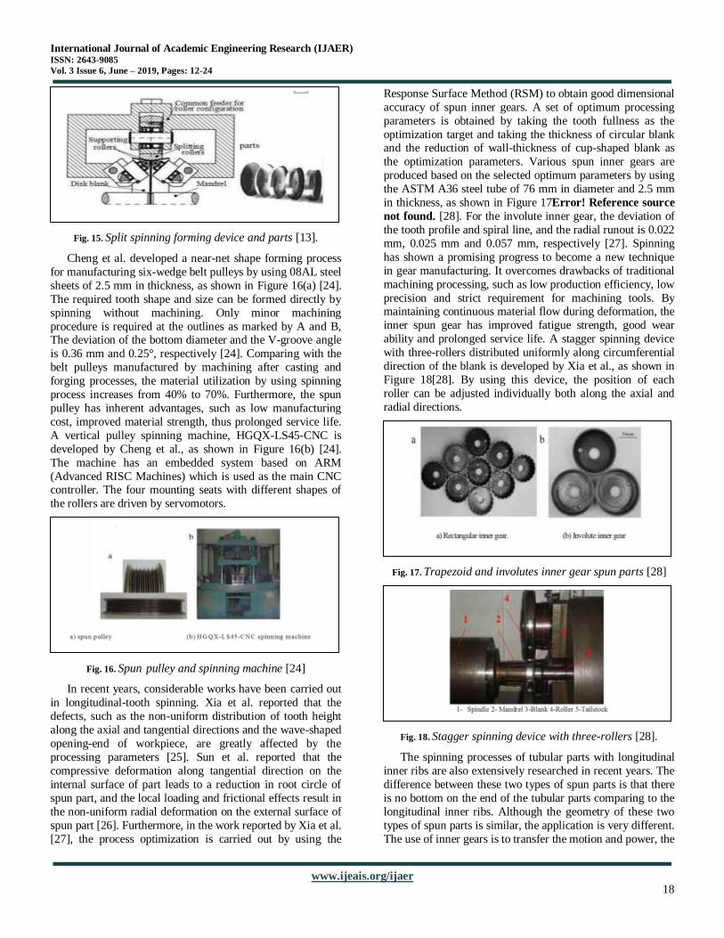
Cheng et al. developed a near-net shape forming process
for manufacturing six-wedge belt pulleys by using 08AL steel
sheets of 2.5 mm in thickness, as shown in Figure 16(a) [24].
The required tooth shape and size can be formed directly by
spinning without machining. Only minor machining
procedure is required at the outlines as marked by A and B, The deviation of the bottom diameter and the V-groove angle
is 0.36 mm and 0.25°, respectively [24]. Comparing with the
belt pulleys manufactured by machining after casting and
forging processes, the material utilization by using spinning
process increases from 40% to 70%. Furthermore, the spun
pulley has inherent advantages, such as low manufacturing
cost, improved material strength, thus prolonged service life.
A vertical pulley spinning machine, HGQX-LS45-CNC is
developed by Cheng et al., as shown in Figure 16(b) [24].
The machine has an embedded system based on ARM
(Advanced RISC Machines) which is used as the main CNC controller. The four mounting seats with different shapes of
the rollers are driven by servomotors.
Fig. 16. Spun pulley and spinning machine [24]
In recent years, considerable works have been carried out
in longitudinal-tooth spinning. Xia et al. reported that the
defects, such as the non-uniform distribution of tooth height
along the axial and tangential directions and the wave-shaped
opening-end of workpiece, are greatly affected by the
processing parameters [25]. Sun et al. reported that the
compressive deformation along tangential direction on the
internal surface of part leads to a reduction in root circle of
spun part, and the local loading and frictional effects result in
the non-uniform radial deformation on the external surface of
spun part [26]. Furthermore, in the work reported by Xia et al.
[27], the process optimization is carried out by using the
Response Surface Method (RSM) to obtain good dimensional
accuracy of spun inner gears. A set of optimum processing
parameters is obtained by taking the tooth fullness as the
optimization target and taking the thickness of circular blank and the reduction of wall-thickness of cup-shaped blank as
the optimization parameters. Various spun inner gears are
produced based on the selected optimum parameters by using
the ASTM A36 steel tube of 76 mm in diameter and 2.5 mm
in thickness, as shown in Figure 17Error! Reference source
not found. [28]. For the involute inner gear, the deviation of
the tooth profile and spiral line, and the radial runout is 0.022
mm, 0.025 mm and 0.057 mm, respectively [27]. Spinning
has shown a promising progress to become a new technique
in gear manufacturing. It overcomes drawbacks of traditional
machining processing, such as low production efficiency, low
precision and strict requirement for machining tools. By maintaining continuous material flow during deformation, the
inner spun gear has improved fatigue strength, good wear
ability and prolonged service life. A stagger spinning device
with three-rollers distributed uniformly along circumferential
direction of the blank is developed by Xia et al., as shown in
Figure 18[28]. By using this device, the position of each
roller can be adjusted individually both along the axial and
radial directions.
Fig. 17. Trapezoid and involutes inner gear spun parts [28]
Fig. 18. Stagger spinning device with three-rollers [28].
The spinning processes of tubular parts with longitudinal
inner ribs are also extensively researched in recent years. The
difference between these two types of spun parts is that there
is no bottom on the end of the tubular parts comparing to the
longitudinal inner ribs. Although the geometry of these two
types of spun parts is similar, the application is very different.
The use of inner gears is to transfer the motion and power, the
International Journal of Academic Engineering Research (IJAER) ISSN: 2643-9085
Vol. 3 Issue 6, June – 2019, Pages: 12-24
www.ijeais.org/ijaer
19
forming quality of the inner gear is essential, especially the
forming accuracy. However, the application of inner ribs is to
enhance the stiffness and strength of tubular parts, only the
accuracy of forming height of inner rib is required to be maintained.
Abd-Eltwab et al, investigated the process of producing
inner longitudinal rips experimentally and theoretically with a
new design performing the process using four balls [29].
This research has tested the effect of process parameters such
as feed ratio, mandrel rotational speed, sleeve initial
thickness, and the depth of feed. The theoretical results were
compared with the experimental work and the deviation ratio
did not exceed 10%.
5. FLOW FORMING
Conventionally, hollow tubes are produced by different
methods like extrusion or drawing. However hot extrusion does not give high dimensional accuracy and is not practical
for thin wall reductions. Drawing is easier and cheaper
compared to extrusion, however, it can result in microcracks
or other defect since it is a tensile operation. Furthermore,
with these methods, generally, annealing is necessary
between the passes which increases the cost of the operation
considerably [30,31]. Flow forming is a chip less, near net
shape technique to produce especially seamless hollow parts
requiring accurate dimensions and high symmetry [32]. The
origins of the flow forming process started in Sweden in the
mid-1950s. However, the process has improved during the last three decades. Flow forming is an advanced form of the
metal spinning process and is sometimes called tube spinning
as well. Gur and Tirosh defined the flow forming process as
an operation involving the simultaneous extrusion (or
drawing) and rolling of the workpiece [33]. According to
Rajan et al. [31], flow forming is a process combining rolling,
shearing and bending into a single operation. Therefore, flow
forming is a very complex process comprising many effects
of different operations. Flow formed components can be used
in different industries including aerospace, defense,
automotive and rail vehicles. Nagele et al. [34], worked on automotive products processed by flow forming.
Components, traditionally produced by machining, have
started to be processed by flow forming mainly because it is
cost effective and good at improving mechanical properties.
Drive shaft flange, output shaft, flanged cylinder and link
shaft components are among the numerous components
produced by flow forming [34].
Flow forming can be applied to many materials including
steel, titanium, aluminum, chromium, zirconium and nickel-
based superalloys and different shapes of components can be
produced as seen in Figure 19 [35].
Flow forming can be considered as an advanced form of metal spinning. The main difference between the two
processes is that the starting material in the metal spinning
process is thinner than for flow forming and the resulting
component is produced from a larger diameter preform
[36,37]. In the flow forming process, the resulting
components dimensions are calculated beforehand, and the
process control is carried out more precisely compared to the metal spinning process. Therefore, if the required dimensions
are not very strict, metal spinning can be chosen due to its
cost effectiveness [36,37][37]. Another difference between
the processes is that the flow forming process is capable of
producing different wall thicknesses on the same component
[36,37].
Fig. 19. Different shape of components produced by flow
forming process
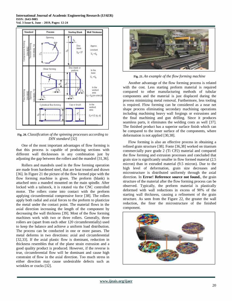
DIN (German Institute of organization) standard 8582
defines the general spinning process. According to this
standard, depending on the process and the shape of the
component, tension and/or compression stresses are applied
during the process. However, the flow forming process is
defined by DIN standard 8584 where only compression forces are applied [32]. Shear forming is also investigated in
the same standard since it involves the same type of
deformation as flow forming. The classification of these
processes according to the DIN standards are given in Figure
20. Generally, the shape of the starting blank (preform) and
the applied force are the main factors for the classification.
There are basically three different methods of flow
forming. Two of them are classified according to the direction
of the flow. These methods are; forward flow forming,
backward flow forming, and shear forming.
International Journal of Academic Engineering Research (IJAER) ISSN: 2643-9085
Vol. 3 Issue 6, June – 2019, Pages: 12-24
www.ijeais.org/ijaer
20
Fig. 20. Classification of the spinning processes according to DIN standard [32]
One of the most important advantages of flow forming is
that this process is capable of producing sections with
different wall thicknesses in any combination just by
adjusting the gap between the rollers and the mandrel [31,36].
Rollers and mandrels used in the flow forming operation
are made from hardened steel, that are heat treated and drawn
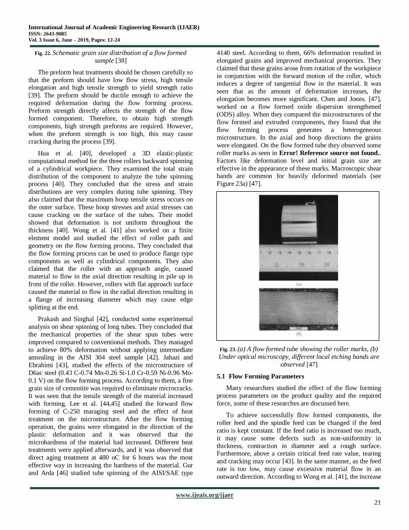
[36]. In Figure 21 the picture of the flow formed pipe with the
flow forming machine is given. The preform (blank) is
attached onto a mandrel mounted on the main spindle. After
locked with a tailstock, it is rotated via the CNC controlled
motor. The rollers come into contact with the preform applying circumferential compressive force [38]. The rollers
apply both radial and axial forces to the preform to plasticize
the metal under the contact point. The material flows in the
axial direction increasing the length of the component by
decreasing the wall thickness [39]. Most of the flow forming
machines work with two or three rollers. Generally, three
rollers are (apart from each other 120 circumferentially) used
to keep the balance and achieve a uniform load distribution.
The process can be conducted in one or more passes. The
metal deforms in two directions: axial and circumferential
[32,33]. If the axial plastic flow is dominant, reduction in thickness resembles that of the plane strain extrusion and a
good quality product is produced. However, if the reverse is
true, circumferential flow will be dominant and cause high
constraint of flow in the axial direction. Too much stress in
either direction may cause undesirable defects such as
wrinkles or cracks [32].
Fig. 21. An example of the flow forming machine
Another advantage of the flow forming process is related
with the cost. Less starting preform material is required
compared to other manufacturing methods of tubular
components and the material is just displaced during the
process minimizing metal removal. Furthermore, less tooling
is required. Flow forming can be considered as a near net shape process eliminating secondary machining operations
including machining heavy wall forgings or extrusions and
the final machining and gun drilling. Since it produces
seamless parts, it eliminates the welding costs as well [37].
The finished product has a superior surface finish which can
be compared to the inner surface of the components, where
deformation is not applied [30,38].
Flow forming is also an effective process in obtaining a
refined grain structure [38]. Fonte [36,38] worked on titanium
commercially pure grade 2 (Ti CP2) material and compared
the flow forming and extrusion processes and concluded that grain size is significantly smaller in flow formed material (2.5
micron) than in extruded material (9.5 micron). Due to the
high level of deformation, grain size decreases and
microstructure is distributed uniformly through the axial
direction. In Error! Reference source not found., the grain
structure of the material after the flow forming process can be
observed. Typically, the preform material is plastically
deformed with wall reductions in excess of 90% of the
starting wall thickness, causing a refinement of the grain
structure. As seen from the Figure 22, the greater the wall
reduction, the finer the microstructure of the finished
component.
International Journal of Academic Engineering Research (IJAER) ISSN: 2643-9085
Vol. 3 Issue 6, June – 2019, Pages: 12-24
www.ijeais.org/ijaer
21
Fig. 22. Schematic grain size distribution of a flow formed
sample [38]
The preform heat treatments should be chosen carefully so
that the preform should have low flow stress, high tensile elongation and high tensile strength to yield strength ratio
[39]. The preform should be ductile enough to achieve the
required deformation during the flow forming process.
Preform strength directly affects the strength of the flow
formed component. Therefore, to obtain high strength
components, high strength preforms are required. However,
when the preform strength is too high, this may cause
cracking during the process [39].
Hua et al. [40], developed a 3D elastic-plastic
computational method for the three rollers backward spinning
of a cylindrical workpiece. They examined the total strain
distribution of the component to analyze the tube spinning process [40]. They concluded that the stress and strain
distributions are very complex during tube spinning. They
also claimed that the maximum hoop tensile stress occurs on
the outer surface. These hoop stresses and axial stresses can
cause cracking on the surface of the tubes. Their model
showed that deformation is not uniform throughout the
thickness [40]. Wong et al. [41] also worked on a finite
element model and studied the effect of roller path and
geometry on the flow forming process. They concluded that
the flow forming process can be used to produce flange type
components as well as cylindrical components. They also claimed that the roller with an approach angle, caused
material to flow in the axial direction resulting in pile up in
front of the roller. However, rollers with flat approach surface
caused the material to flow in the radial direction resulting in
a flange of increasing diameter which may cause edge
splitting at the end.
Prakash and Singhal [42], conducted some experimental
analysis on shear spinning of long tubes. They concluded that
the mechanical properties of the shear spun tubes were
improved compared to conventional methods. They managed
to achieve 80% deformation without applying intermediate annealing in the AISI 304 steel sample [42]. Jahazi and
Ebrahimi [43], studied the effects of the microstructure of
D6ac steel (0.43 C-0.74 Mn-0.26 Si-1.0 Cr-0.59 Ni-0.96 Mo-
0.1 V) on the flow forming process. According to them, a fine
grain size of cementite was required to eliminate microcracks.
It was seen that the tensile strength of the material increased
with forming. Lee et al. [44,45] studied the forward flow
forming of C-250 maraging steel and the effect of heat
treatment on the microstructure. After the flow forming
operation, the grains were elongated in the direction of the
plastic deformation and it was observed that the
microhardness of the material had increased. Different heat treatments were applied afterwards, and it was observed that
direct aging treatment at 480 oC for 6 hours was the most
effective way in increasing the hardness of the material. Gur
and Arda [46] studied tube spinning of the AISI/SAE type
4140 steel. According to them, 66% deformation resulted in
elongated grains and improved mechanical properties. They
claimed that these grains arose from rotation of the workpiece
in conjunction with the forward motion of the roller, which induces a degree of tangential flow in the material. It was
seen that as the amount of deformation increases, the
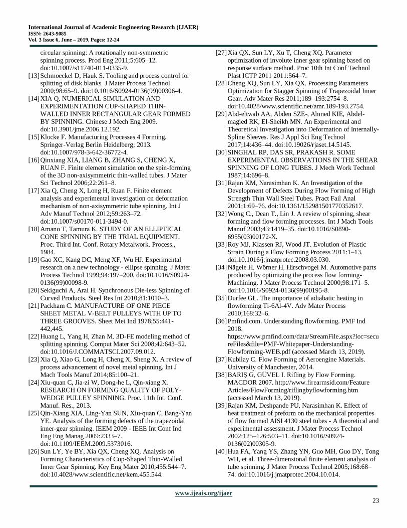
elongation becomes more significant. Chen and Jones. [47],
worked on a flow formed oxide dispersion strengthened
(ODS) alloy. When they compared the microstructures of the
flow formed and extruded components, they found that the
flow forming process generates a heterogeneous
microstructure. In the axial and hoop directions the grains
were elongated. On the flow formed tube they observed some
roller marks as seen in Error! Reference source not found..
Factors like deformation level and initial grain size are
effective in the appearance of these marks. Macroscopic shear bands are common for heavily deformed materials (see
Figure 23a) [47].
Fig. 23. (a) A flow formed tube showing the roller marks, (b)
Under optical microscopy, different local etching bands are
observed [47]
5.1 Flow Forming Parameters
Many researchers studied the effect of the flow forming
process parameters on the product quality and the required
force, some of these researches are discussed here.
To achieve successfully flow formed components, the
roller feed and the spindle feed can be changed if the feed
ratio is kept constant. If the feed ratio is increased too much,
it may cause some defects such as non-uniformity in
thickness, contraction in diameter and a rough surface. Furthermore, above a certain critical feed rate value, tearing
and cracking may occur [43]. In the same manner, as the feed
rate is too low, may cause excessive material flow in an
outward direction. According to Wong et al. [41], the increase
International Journal of Academic Engineering Research (IJAER) ISSN: 2643-9085
Vol. 3 Issue 6, June – 2019, Pages: 12-24
www.ijeais.org/ijaer
22
in the spindle speed affects the process in two ways. First
there is an increased magnitude of spinning force due to high
deformation rate. Secondly the deformation energy required
per revolution is likely to decrease.
Rajan et al. [31], studied the typical defects that can occur
during the flow forming process. They worked on AISI 4130
steel tube and investigated the defects like diametral growth,
premature burst, buildup, fish scaling and bell mouthing.
They managed to produce high strength thin wall tubes with
good dimensional accuracy by controlling the machining
properties like feed rate, spindle speed and roller geometry.
They concluded that a homogeneous microstructure and good
formability are the essential factors to obtain heavily
deformed flow formed samples without any defects [31].
Davidson et al. [48], studied the effect of feed rate during
flow forming aluminum alloy AA6061 tubes. It was seen that, especially at the early stages of the deformation, a feed rate
less than 50 mm/min can cause the internal diameter to
increase. This is due to the fact that a low feed rate causes the
plastic deformation to delay. Therefore, material flows in the
radial direction rather than in axial direction. When the feed
rate is higher than 100 mm/min, it can result in a wavy like
appearance at the surface. The reason is fast moving rollers
due to the high feed rate can cause a surface quality problem.
It was found that a feed rate of around 30mm/min is ideal for
a fine surface finish [48]. Nagarajan et al. [49], claimed that
1.4 to 1.7 mm/rev of feed rate is optimum for a good product. If the rate is below this range, fracture may occur and if it is
above this value, marks can appear at the surface of the
finished product. The roller path has also an effect on the
quality of the product. A wrong roller path choice may cause
buckling and wrinkles as well as cracking. Also, the roller
design must be done correctly considering the shape and
thickness of the component. Roller design is effective in the
components shape, thickness and dimensional accuracy. As
long as the roller diameter is big enough to prevent higher
stresses and non-uniform thickness distribution, the diameter
is not the most significant parameter on the quality of the component. Correct roller path should be carried out to
prevent defects like buckling, wrinkles and cracking [32]. For
spinning process generally, a concave roller path is chosen.
Spinning ratio is the ratio of the preform diameter to mandrel
diameter. As the spinning ratio increases, the process
becomes harder since it is difficult for the remaining material
cross section to transmit the stress [32].
According to Davidson et al. [48], an optimum depth of
cut is a necessary parameter for a good surface finish. Fish
scaling marks may occur on the surface due to the small
depth of cut whereas very high depth can result in delay in
plastic deformation and produce highly strained roller profiles on the surface [48]. The speed of the mandrel should be high
enough to achieve a defect free surface yet vibrations in the
machines should be avoided. Furthermore, excessive speeds
can result in increased adiabatic temperature causing plastic
instabilities [48].
6. SUGGESTIONS
The review of the two processes of spinning and flow
forming may leads us to think why there is no one process
has the ability to conduct the two processes in one pass; why we cannot manufacture a thin wall cup without two
subsequent processes.
The conventional spinning process can be performed with
balls or not? Why no one tried to perform the conventional
spinning process with a metallic ball. What if the ball has the
ability to rotate about its center in the three directions; will
this affect the spinning process.
Can we perform the two processes in the same stroke with
a ball or a set of Consecutive balls!!!
The manufacturing of a thin wall cup in one pass is
believed to reduce the part cost by reducing the
manufacturing time and may also reduce the required power for the process.
REFERENCES
[1] Engineeringarticles.org. Manufacturing Process
Meaning & Types 2015.
http://www.engineeringarticles.org/manufacturing-
process-meaning-and-types/ (accessed March 12, 2019).
[2] Runge M. Spinning and flow forming. Leifield GmbH;
1994.
[3] Wick C, Drozda T, Bakerjian R, Petro L, Veilleux RF.
Tool and manufacturing engineers handbook: Forming.
vol. II. 1984. [4] Hagan E, Jeswiet J. A review of conventional and
modern single-point sheet metal forming methods. Proc
Inst Mech Eng Part B J Eng Manuf 2003;217:213–25.
doi:10.1243/095440503321148858.
[5] Wang L. Analysis of Material Deformation and
Wrinkling Failure in Conventional Metal Spinning
Process. 2012.
[6] Hamilton S, Long H. Analysis of Conventional Spinning
Process of a Cylindrical Part Using Finite Element
Methods 2010:0-.
[7] Kegg RL. A New Test Method for Determination of Spinnability of Metals. J Eng Ind 1961;83:119.
doi:10.1115/1.3664438.
[8] Kalpakcioglu S. A Study of Shear-Spinnability of
Metals. J Eng Ind 2011;83:478. doi:10.1115/1.3664570.
[9] Music O, Allwood JM, Kawai K. A review of the
mechanics of metal spinning. J Mater Process Technol
2010;210:3–23.
doi:10.1016/J.JMATPROTEC.2009.08.021.
[10] Xia Q. Investigation on the mechanism of the spinning
technology of the 3D non-axisymmetric parts. Chinese J
Mech Eng - CHIN J MECH ENG 2004;40.
doi:10.3901/JME.2004.02.153. [11] Awiszus B, Meyer F. Metal Spinning of Non-Circular
Hollow Parts. 8th Int Conf Technol Plast 2005:9–13.
[12] Awiszus B, Härtel S. Numerical simulation of non-
International Journal of Academic Engineering Research (IJAER) ISSN: 2643-9085
Vol. 3 Issue 6, June – 2019, Pages: 12-24
www.ijeais.org/ijaer
23
circular spinning: A rotationally non-symmetric
spinning process. Prod Eng 2011;5:605–12.
doi:10.1007/s11740-011-0335-9.
[13] Schmoeckel D, Hauk S. Tooling and process control for splitting of disk blanks. J Mater Process Technol
2000;98:65–9. doi:10.1016/S0924-0136(99)00306-4.
[14] XIA Q. NUMERICAL SIMULATION AND
EXPERIMENTATION CUP-SHAPED THIN-
WALLED INNER RECTANGULAR GEAR FORMED
BY SPINNING. Chinese J Mech Eng 2009.
doi:10.3901/jme.2006.12.192.
[15] Klocke F. Manufacturing Processes 4 Forming.
Springer-Verlag Berlin Heidelberg; 2013.
doi:10.1007/978-3-642-36772-4.
[16] Qinxiang XIA, LIANG B, ZHANG S, CHENG X,
RUAN F. Finite element simulation on the spin-forming of the 3D non-axisymmetric thin-walled tubes. J Mater
Sci Technol 2006;22:261–8.
[17] Xia Q, Cheng X, Long H, Ruan F. Finite element
analysis and experimental investigation on deformation
mechanism of non-axisymmetric tube spinning. Int J
Adv Manuf Technol 2012;59:263–72.
doi:10.1007/s00170-011-3494-0.
[18] Amano T, Tamura K. STUDY OF AN ELLIPTICAL
CONE SPINNING BY THE TRIAL EQUIPMENT.
Proc. Third Int. Conf. Rotary Metalwork. Process.,
1984. [19] Gao XC, Kang DC, Meng XF, Wu HJ. Experimental
research on a new technology - ellipse spinning. J Mater
Process Technol 1999;94:197–200. doi:10.1016/S0924-
0136(99)00098-9.
[20] Sekiguchi A, Arai H. Synchronous Die-less Spinning of
Curved Products. Steel Res Int 2010;81:1010–3.
[21] Packham C. MANUFACTURE OF ONE PIECE
SHEET METAL V-BELT PULLEYS WITH UP TO
THREE GROOVES. Sheet Met Ind 1978;55:441-
442,445.
[22] Huang L, Yang H, Zhan M. 3D-FE modeling method of splitting spinning. Comput Mater Sci 2008;42:643–52.
doi:10.1016/J.COMMATSCI.2007.09.012.
[23] Xia Q, Xiao G, Long H, Cheng X, Sheng X. A review of
process advancement of novel metal spinning. Int J
Mach Tools Manuf 2014;85:100–21.
[24] Xiu-quan C, Jia-zi W, Dong-he L, Qin-xiang X.
RESEARCH ON FORMING QUALITY OF POLY-
WEDGE PULLEY SPINNING. Proc. 11th Int. Conf.
Manuf. Res., 2013.
[25] Qin-Xiang XIA, Ling-Yan SUN, Xiu-quan C, Bang-Yan
YE. Analysis of the forming defects of the trapezoidal
inner-gear spinning. IEEM 2009 - IEEE Int Conf Ind Eng Eng Manag 2009:2333–7.
doi:10.1109/IEEM.2009.5373016.
[26] Sun LY, Ye BY, Xia QX, Cheng XQ. Analysis on
Forming Characteristics of Cup-Shaped Thin-Walled
Inner Gear Spinning. Key Eng Mater 2010;455:544–7.
doi:10.4028/www.scientific.net/kem.455.544.
[27] Xia QX, Sun LY, Xu T, Cheng XQ. Parameter
optimization of involute inner gear spinning based on
response surface method. Proc 10th Int Conf Technol
Plast ICTP 2011 2011:564–7. [28] Cheng XQ, Sun LY, Xia QX. Processing Parameters
Optimization for Stagger Spinning of Trapezoidal Inner
Gear. Adv Mater Res 2011;189–193:2754–8.
doi:10.4028/www.scientific.net/amr.189-193.2754.
[29] Abd-eltwab AA, Abden SZE-, Ahmed KIE, Abdel-
magied RK, El-Sheikh MN. An Experimental and
Theoretical Investigation into Deformation of Internally-
Spline Sleeves. Res J Appl Sci Eng Technol
2017;14:436–44. doi:10.19026/rjaset.14.5145.
[30] SINGHAL RP, DAS SR, PRAKASH R. SOME
EXPERIMENTAL OBSERVATIONS IN THE SHEAR
SPINNING OF LONG TUBES. J Mech Work Technol 1987;14:696–8.
[31] Rajan KM, Narasimhan K. An Investigation of the
Development of Defects During Flow Forming of High
Strength Thin Wall Steel Tubes. Pract Fail Anal
2001;1:69–76. doi:10.1361/152981501770352617.
[32] Wong C., Dean T., Lin J. A review of spinning, shear
forming and flow forming processes. Int J Mach Tools
Manuf 2003;43:1419–35. doi:10.1016/S0890-
6955(03)00172-X.
[33] Roy MJ, Klassen RJ, Wood JT. Evolution of Plastic
Strain During a Flow Forming Process 2011:1–13. doi:10.1016/j.jmatprotec.2008.03.030.
[34] Nägele H, Wörner H, Hirschvogel M. Automotive parts
produced by optimizing the process flow forming-
Machining. J Mater Process Technol 2000;98:171–5.
doi:10.1016/S0924-0136(99)00195-8.
[35] Durfee GL. The importance of adiabatic heating in
flowforming Ti-6Al-4V. Adv Mater Process
2010;168:32–6.
[36] Pmfind.com. Understanding flowforming. PMF Ind
2018.
https://www.pmfind.com/data/StreamFile.aspx?loc=secureFiles&file=PMF-Whitepaper-Understanding-
Flowforming-WEB.pdf (accessed March 13, 2019).
[37] Kubilay C. Flow Forming of Aeroengine Materials.
University of Manchester, 2014.
[38] BARIŞ G, GÜVEL I. Rifling by Flow Forming.
MACDOR 2007. http://www.firearmsid.com/Feature
Articles/FlowForming/riflingbyflowforming.htm
(accessed March 13, 2019).
[39] Rajan KM, Deshpande PU, Narasimhan K. Effect of
heat treatment of preform on the mechanical properties
of flow formed AISI 4130 steel tubes - A theoretical and
experimental assessment. J Mater Process Technol 2002;125–126:503–11. doi:10.1016/S0924-
0136(02)00305-9.
[40] Hua FA, Yang YS, Zhang YN, Guo MH, Guo DY, Tong
WH, et al. Three-dimensional finite element analysis of
tube spinning. J Mater Process Technol 2005;168:68–
74. doi:10.1016/j.jmatprotec.2004.10.014.

International Journal of Academic Engineering Research (IJAER) ISSN: 2643-9085
Vol. 3 Issue 6, June – 2019, Pages: 12-24
www.ijeais.org/ijaer
24
[41] Wong CC, Dean TA, Lin J. Incremental forming of solid
cylindrical components using flow forming principles. J
Mater Process Technol 2004;153–154:60–6.
doi:10.1016/j.jmatprotec.2004.04.102. [42] Prakash R, Singhal RP. Shear spinning technology for
manufacture of long thin wall tubes of small bore. J
Mater Process Tech 1995;54:186–92. doi:10.1016/0924-
0136(95)01940-5.
[43] Jahazi M, Ebrahimi G. Influence of flow-forming
parameters and microstructure on the quality of a D6ac
steel. J Mater Process Technol 2000;103:362–6.
doi:10.1016/S0924-0136(00)00508-2.
[44] Lee Y-J, Lee I-K, Wu S-C, Kung M-C, Chou C-P.
Effect of post-weld heat treatments on microstructure
and mechanical properties of electron beam welded flow
formed maraging steel weldment. Sci Technol Weld Join 2007;12:266–73. doi:10.1179/174329307X173689.
[45] Lee IK, Chou CP, Cheng CM, Kuo IC. Effect of heat
treatment on microstructures of flow formed C-250
maraging steel. Mater Sci Technol 2003;19:1595–602.
doi:10.1179/026708303225008095.
[46] Gür CH, Arda EB. Effect of tube spinning and
subsequent heat treatments on strength, microstructure
and residual stress state of AISI/SAE type 4140 steel.
Mater Sci Technol 2003;19:1590–4.
doi:10.1179/026708303225008022.
[47] Chen YL, Jones AR. The Microstructure and Recrystallization of Flow-Formed Oxide-Dispersion-
Strengthened Ferritic Alloy: Part I. Deformation
Structure. Metall Mater Trans A Phys Metall Mater Sci
2002;33:3787–94. doi:10.1007/s11661-002-0251-x.
[48] Joseph Davidson M, Balasubramanian K, Tagore GRN.
An experimental study on the quality of flow-formed
AA6061 tubes. J Mater Process Technol 2008;203:321–
5. doi:10.1016/J.JMATPROTEC.2007.10.021.
[49] Nagarajan HN, Kotrappa H, Mallanna C, Venkatesh
VC. Mechanics of Flow Forming. CIRP Ann - Manuf
Technol 1981;30:159–62. doi:10.1016/S0007-8506(07)60915-9.