Embed Size (px)
Citation preview
Chapter 28 – Ventilation
JANUARY 2017
This latest edition incorporates all rule changes. The latest revisions are shown with a vertical line. The section title is framed if the section is revised completely. Changes after the publication of the rule are written in red colour.
Unless otherwise specified, these Rules apply to ships for which the date of contract for construction as defined in IACS PR No.29 is on or after 1st of August 2016. New rules or amendments entering into force after the date of contract for construction are to be applied if required by those rules. See Rule Change Notices on TL website for details.
"General Conditions" of the respective latest edition will be applicable (see Rules for Classification and Surveys).
If there is a difference between the rules in English and in Turkish, the rule in English is to be considered as valid. This publication is available in print and electronic pdf version. Once downloaded, this document will become UNCONTROLLED. Please check the website below for the valid version.
http:/www.turkloydu.org
All rights are reserved by Türk Loydu, and content may not be reproduced, disseminated, published, or transferred in any form or by any means, except with the prior written permission of TL.

TÜRK LOYDU
Head Office Postane Mah. Tersaneler Cad. No:26 Tuzla 34944 İSTANBUL / TÜRKİYE
Tel : (90-216) 581 37 00
Fax : (90-216) 581 38 00
E-mail : [email protected]
http://www.turkloydu.org
Regional Offices
Ankara Eskişehir Yolu Mustafa Kemal Mah. 2159. Sokak No : 6/4 Çankaya - ANKARA / TÜRKİYE
Tel : (90-312) 219 56 34
Fax : (90-312) 219 68 25
E-mail : [email protected]
İzmir Atatürk Cad. No :378 K.4 D.402 Kavalalılar Apt. 35220 Alsancak - İZMİR / TÜRKİYE
Tel : (90-232) 464 29 88
Fax : (90-232) 464 87 51
E-mail : [email protected]
Adana Çınarlı Mah. Atatürk Cad. Aziz Naci İş Merkezi No:5 K.1 D.2 Seyhan - ADANA / TÜRKİYE
Tel : (90- 322) 363 30 12
Fax : (90- 322) 363 30 19
E-mail : [email protected]
Marmaris Atatürk Cad. 99 Sok. No:1 Ketenbaş Apt. Kat:4 Daire 6 Marmaris - MUĞLA / TÜRKİYE
Tel : (90- 252) 412 46 55
Fax : (90- 252) 412 46 54
E-mail : [email protected]

Contents
Ventilation
Page Section 1 – General Rules and Instructions
A. General .............................................................................................................................................................. 1- 3
B. Documents to be Submitted For Approval .......................................................................................................... 1- 3
C. Definitions .......................................................................................................................................................... 1- 4
D. General Requirements ....................................................................................................................................... 1- 6
E. Requirements For Particular Spaces .................................................................................................................. 1- 13
F. Ventilation Requirements For the Carriage of Dangeros Goods ........................................................................ 1- 20
G. Refrigerated Containers ..................................................................................................................................... 1- 22
H. Cargo Spaces For the Carriage of Vehicles With Fuel in Their Tanks And
Cargo Spaces of Ro-Ro Ships .......................................................................................................................... 1- 22
I. Additional Rules For Passenger Vessels ........................................................................................................... 1- 24
J. Special Class Notation Ahts ............................................................................................................................... 1- 27
K. Additional Rules For Tankers ............................................................................................................................. 1- 28
L. Air Changes Per Hour ........................................................................................................................................ 1- 28
Annex A - Recommendations
A. General Arrangement ....................................................................................................................................... 1- 2
B. Testing .............................................................................................................................................................. 1- 2
C. Ventilation Equipment ....................................................................................................................................... 1- 2
D. Machinery Space Ventilation ............................................................................................................................. 1- 2
E. Cargo Holds ...................................................................................................................................................... 1- 2
F. Emergency Generator Room ............................................................................................................................ 1- 2
G. Refrigerated Containers .................................................................................................................................... 1- 2
H. Livestock Carrier……………………………………………………………………………………………………….. 1- 3
I. Principal Construction of Duct Penetretion Through “A” Class Bulkheads
or Decks ............................................................................................................................................................ 1- 3
J. Air Changes Per Hour ....................................................................................................................................... 1- 3

AMENDMENTS
* Entry into Force (EIF) Date is provided for general guidance only, EIF dates given in Rule Change Summary(RCS) are considered valid. In addition to the above stated changes, editorial corrections may have been made.
Revised Sections RCS No. EIF Date
Section 01 04/2017 01.01.2018

Section 1 – Ventilation 1-1
SECTION 1
VENTILATION
Page A. GENERAL .......................................................................................................................................................... 1- 3
1. Application2. Other Apllicable Rules
3. International Standards
B. DOCUMENTS TO BE SUBMITTED FOR APPROVAL ..................................................................................... 1- 3
C. DEFINITIONS ..................................................................................................................................................... 1- 4 D. GENERAL REQUIREMENTS ............................................................................................................................ 1- 6
1. Genera Arrangements
2. Ventilator Coamings
3. Weathertight Closing Appliances
4. Fire Closures/Dampers
5. Ventilation Ducts
6. Non-sparking Fans
7. Additional Fire Safety Arrangements
E. REQUIREMENTS FOR PARTICULAR SPACES .............................................................................................. 1- 13 1. Accommodation Spaces
2. Galleys
3. Control Stations
4. Paint Stores and Flammable Liquid Lockers
5. Machinery Space Ventilation
6. Electrical Machines
7. CO2 Rooms
8. Refrigerating Machinery Rooms
9. Spaces Containing Batteries
10. Separator Spaces
11. Emergency Generator Rooms
12. Emergency Fire Pump Room
13. Pipe Tunnels
14. Thruster Rooms
15. Oxygen-acetylene Storage Rooms
16. Storage Places of Gas Bottlers for Domestic Purpose
17. Helicopter refuelling and Hangar Facilities
F. VENTILATION REQUIREMENTS FOR THE CARRIAGE OF DANGEROS GOODS ....................................... 1- 20
1. Zone 1 (Hazardous Area)
2. Zone 2 ( Extented Hazardous Area)
3. Cargo Holds
4. Dangerous Goods in Packaged form5. Solid Dangerous Goods in Bulk and Materials Hazardous only in Bulk
G. REFRIGERATED CONTAINERS ...................................................................................................................... 1- 22
TÜRK LOYDU – VENTILATION – JANUARY 2017

1-2 Section 1 – Ventilation H. CARGO SPACES FOR THE CARRIAGE OF VEHICLES with FUEL IN THEIR TANKS AND CARGO SPACES OF RO-RO SHIPS ............................................................................................................... 1- 22 1. Capacity of Ventilation System
2. Perfomance and Design of Ventilation Systems
3. Closing Appliances and Ducts
4. Permanent Openings
5. Electrical Equipment and Cable Installation I. ADDITIONAL RULES FOR PASSENGER VESSELS ....................................................................................... 1- 24
1. General
2. Additional Rules for Passenger Vessels Carrying Not More Than 36 Passengers
3. Rules for Passenger Vessels Carrying More Than 36 Passengers J. SPECIAL CLASS NOTATION AHTS ................................................................................................................ 1- 27
1. General
2. Documents to be Submitted
3. Requirements
4. Testing
K. ADDITIONAL RULES FOR TANKERS ............................................................................................................. 1- 28
L. AIR CHANGES PER HOUR .............................................................................................................................. 1- 28
TÜRK LOYDU – VENTILATION – JANUARY 2017

A,B Section 1 – Ventilation 1-3
A. General 1. Application 1.1 These rules apply to ships to be classed for unrestricted service. For ships classed for restricted service or ships which are intended to trade within specified limits as well as for small cargo vessels of less than convention size (< 500 GT), small fishing vessels, pontoons without propulsion, barges and dredgers without propulsion and pleasure craft (yachts, etc.) exemptions from the requirements of these rules may be permitted. 1.2 Designs which deviate from these rules may be approved provided that such designs have been examined by TL for suitability and have been recognized as equivalent. 1.3 National rules or regulations remain unaffected. 1.4 Annex A contains recommendations which are not a matter of Classification. 2. Other Applicable Rules In addition to the requirements of these rules:
- Tankers for the carriage of flammable liquids
are subject to the provisions of TL Machinery
Rules, Chapter 4, Section 15
- Tankers for the carriage of liquefied gases in
bulk are subject to the provisions of the TL
Rules for Liquefied Gas Carriers, Chapter 10
- Tankers for the carriage of hazardous
chemicals in bulk are subject to the provisions
of TL Rules for Chemical Tankers, Chapter 8
- Seagoing and inland waterway steel vessels
with or without their own means of propulsion
which are intended for service in the event of
accidental oil spills are subject to the
provisions of TL Rules for Oil Recovery
Vessels, Chapter 12
- Ships intended for the carriage of dangerous goods in packaged form and for the carriage of solid bulk cargoes are subject to the provisions of TL Machinery Rules, Section 18, P and Q and Electrical Installations, Section 17, D
- Ventilation systems for ships with gas as fuel are
subject to TL Guidelines for the Use of Gas as Fuel for Ships. 3. International Standards For design and construction of ventilation systems the following international standards are recommended as guidance. The last edition of each standard should be applied. - ISO 7547, Shipbuilding – Air-conditioning and
ventilation of accommodation spaces on board Zships – Design conditions and basis of calculations
- ISO 8861, Shipbuilding – Engine room ventilation
in diesel-engined ships – Design requirements and basis of calculations
- ISO 8862, Air-conditioning and ventilation of
machinery control rooms on board ships – Design conditions and basis of calculations
- ISO 8864, Shipbuilding – Air conditioning and
ventilation of wheelhouse on board ships – Design conditions and basis of calculations
- ISO 9785, Ships and marine technology –
Ventilation of cargo spaces where vehicles with Internal combustion are driven
- ISO 9943, Shipbuilding – Ventilation and air-
treatment of galleys and pantries with cooking appliances
B. Documents to be Submitted for Approval
The following documents are to be submitted in
triplicate to TL for approval. TL reserve its right to ask
for supplementary copies, if deemed necessary.
TÜRK LOYDU – VENTILATION – JANUARY 2017

1-4 Section 1 – Ventilation B,C
- Ventilation and air condition scheme –
accommodation and service spaces
- Ventilation system machinery spaces and
technical spaces
- Ventilation system cargo holds
- Details of fire closures and weather tight closures
- Details of duct penetrations
- Approval information (flexible ducts, fire
dampers, duct penetrations)
- Principal electrical supply, control and monitoring
- Emergency stops of fans
C. Definitions
For the purposes of these regulations the following
definitions shall apply:
1. Accommodation Spaces
Spaces used for public spaces, corridors, lavatories,
cabins, offices, hospitals, cinemas, games and hobbies
rooms, barber shops, pantries containing no cooking
appliances and similar spaces.
2. Air Ducts
Thin-walled piping or ducting (circular or rectangular)
used exclusively to conduct air.
3. Air Pipes
Parts of tank pressure-equalizing systems not dealt with
in these regulations, see TL Hull Rules, Section 21, E
4. Air Trunks Parts of the hull which may either themselves be used
to conduct air or which contain air ducts as well as other
lines (pipes, cables).
5. Approved Type
The term "Approved" relates to a material or
construction, for which TL has issued an Approval
Certificate. A type approval can be issued on the basis
of a successful standard fire test, which has been
carried out by a neutral and recognized fire testing
institute. 6. Cargo Spaces All spaces used for cargo, cargo oil tanks, tanks for other liquid cargo and trunks to such spaces. 7. Closed Ro-Ro cargo Spaces All Ro-Ro cargo spaces which are neither open Ro-Ro cargo spaces nor weather decks. 8. Control Stations Those spaces in which the ship's radio or main navigating equipment or the emergency source of power is located or where the fire recording or fire control equipment is centralized. 9. Fire Closures
Closing appliances of ventilation inlets and outlets as
required by SOLAS II-2/5.2.1.1 for fire protection
purposes.
10. Free Cross-sectional Area
Means, even in the case of a pre-insulated duct, the
area calculated on the basis of the inner diameter of the
duct.
11. LLC 1966
International Load Line Convention 1966, as amended. 12. Machinery Spaces
All machinery spaces of category A and all other spaces
containing propulsion machinery, boilers, oil fuel units,
steam and internal combustion engines, generators and
major electrical machinery, oil filling stations, and similar
spaces, and trunks to such spaces.
TÜRK LOYDU – VENTILATION – JANUARY 2017
C Section 1 – Ventilation 1-5
13. Machinery Spaces of Category A
Those spaces and trunks to such spaces which contain:
- Internal combustion machinery used for main
propulsion
- Internal combustion machinery used for
purposes other than main propulsion where
such machinery has in the aggregate a total
power output of not less than 375 kW
- Any oil-fired boiler or oil fuel unit, or any oil-
fired equipment other than boilers, such as
inert gas generators, incinerators, etc.
14. Mechanical Ventilation Systems
Systems through which air is passed by ventilators
driven hydraulically, pneumatically or by electric motors.
Mechanical ventilation may also be called power
ventilation or forced ventilation. 15. Natural Ventilation Systems
Systems in which the air movement is caused solely by
temperature differences, natural wind or head wind.
16. Non-combustible Material
Is a material which neither burns nor gives off
flammable vapours in sufficient quantity for self-ignition
when heated to approximately 750 °C, this being
determined in accordance with Fire Test Procedure
Code.
17. Non-sparking Fans
A fan is considered as non-sparking if in either normal
or abnormal conditions it is unlikely to produce sparks. 18. Open Ro-Ro spaces
Those Ro-Ro spaces which are either open at both
ends or have an opening at one end, and are provided
with adequate natural ventilation effective over their
entire length through permanent openings distributed in
the side plating or deckhead or from above, having a
total area of at least 10 % of the total area of the space
side.
19. Public Spaces
Those portions of the accommodation which are used
for halls, dining rooms, lounges and similar permanently
enclosed spaces.
20. Ro-Ro Cargo Spaces
Spaces not normally subdivided in any way and
normally extending to either a substantial length or the
entire length of the ship in which motor vehicles with
fuel in their tanks for their own propulsion and/or goods
(packaged or in bulk, in or on rail or road cars, vehicles
(including road or rail tankers), trailers, containers,
pallets, demountable tanks or in or on similar stowage
units or other receptacles) can be loaded and unloaded
normally in a horizontal direction.
21. Service Spaces
Those spaces used for galleys, pantries containing
cooking appliances, lockers, mail and specie rooms,
store-rooms, workshops other than those forming part of
the machinery spaces, and similar spaces and trunks to
such spaces.
22. Special Category Spaces
Enclosed spaces above or below the bulkhead deck
intended for the carriage of motor vehicles with fuel in
their tanks for their own propulsion, into and from which
such vehicles can be driven and to which passengers
have access.
23. Vehicle Spaces
Cargo spaces intended for carriage of motor vehicles
with fuel in their tanks for their own propulsion.
24. Ventilator Coamings
Those thick-walled portions of air ducts which extend
above a weather deck and are welded to it (cf.
Regulation 19, LLC 1966).
TÜRK LOYDU – VENTILATION – JANUARY 2017
1-6 Section 1 – Ventilation C,D
25. Weather Deck
Is a deck which is completely exposed to the weather
from above and from at least two sides.
D. General Requirements 1. General Arrangements
1.1 The ventilation systems for machinery spaces
of category A, vehicle spaces, Ro-Ro spaces, galleys,
special category spaces and cargo spaces shall, in
general, be separated from each other and from the
ventilation systems serving other spaces.
Exceptions are the galley ventilation systems on cargo
ships of less than 4000 gross tonnage and in passenger
ships carrying not more than 36 passengers, which
need not be completely separated, but may be served
by separate ducts from a ventilation unit serving other
spaces. In this case, an automatic fire damper shall be
fitted in the galley ventilation ducts near the ventilation
unit.
1.2 Balance openings or ducts between two
enclosed spaces are prohibited except for openings in
or under "B" class doors. Such openings shall be
provided only in the lower half of the door. Where such
an opening is in or under a door, the total net area of
any such opening or openings shall not exceed 0.05 m2.
Alternatively, a non-combustible air balance duct routed
between the cabin and the corridor, and located below
the sanitary unit, is permitted where the cross-sectional
area of the duct does not exceed 0.05 m2. Ventilation
openings, except those under the door, shall be fitted
with a grill made of noncombustible material.
1.3 Where necessary, main intakes and outlets are
to be fitted with gratings to prevent fouling and the entry
of rats and other large vermin.
1.4 Where a fixed gas fire-extinguishing system is
fitted, ventilation openings of these spaces shall be
capable of being closed from outside the protected
space. If the closures are not fitted directly at the
external bulkhead of the protected space the duct
between bulkhead, and closing device shall be
constructed of steel having a thickness of at least 3 mm
and flange joints are to be sealed by non-combustible
material.
1.5 Where individual rooms have separate
arrangements for flooding with CO2, the ventilating
system must also be separate. Provision is to be made
to remove CO2, after flooding of these spaces.
1.6 Electrical machinery and installations (switch
cabinets, etc.) are to be protected such that water
particles penetrating into the air ducts will not cause
disturbances. Risks of this kind are to be minimized by
appropriate arrangement (water traps) of ducts and air
in/outlets.
1.7 The number of ventilation openings in watertight
subdivisions shall be reduced to the minimum compatible
with the design and proper working of the ship. Where
ventilation ducts are routed through watertight decks and
bulkheads, arrangements shall be made to ensure the
watertight integrity. If valves are provided at watertight
boundaries to maintain watertight integrity, than the valves
are to be capable of being operated from a control panel
located in the navigation bridge, where the position of the
shut-off valves is to be indicated.
2. Ventilator Coamings 2.1 General requirements
2.1.1 The height of the ventilator coamings on the
exposed freeboard deck, quarter deck and on exposed
superstructure decks in the range 0.25 L from F.P. is to
be at least 900 mm, see Fig. 1.1.
2.1.2 On exposed superstructure decks abaft 0.25 L
from F.P. the coaming height is not to be less than 760
mm.
2.1.3 Ventilators of cargo holds are not to have any
connection with other spaces.
2.1.4 The thickness of the coaming plates is to be
7.5 mm where the clear opening sectional area of the
ventilator coamings is 300 cm2 or less, and 10 mm
where the clear opening sectional area exceeds 1600
cm2. Intermediate values are to be determined by direct
TÜRK LOYDU – VENTILATION – JANUARY 2017

D Section 1 – Ventilation 1-7
interpolation. A thickness of 6 mm will generally be
sufficient within not permanently closed superstructures.
2.1.5 The thickness of ventilator posts shall be at
least equal to the thickness of coaming as per 2.1.4.
2.1.6 The wall thickness of ventilator posts of a clear
sectional area exceeding 1600 cm2 is to be increased
according to the expected loads.
2.1.7 Generally, the coamings and posts shall pass
through the deck and shall be welded to the deck
plating from above and below. Where coamings or
posts are welded onto the deck plating, filet welds
subject of Hull Rules, Section 19, B.3.3 shall be adopted
for welding inside and outside.
2.1.8 Coamings and posts particularly exposed to
wash of sea are to be efficiently connected with the
ship's structure.
Figure 1.1 Minimum coaming height [mm] for ventilators according to LLC 66 as amended
2.1.9 Coamings of a height exceeding 900 mm are
to be specially strengthened.
2.1.10 Where the thickness of the deck plating is less
than 10 mm, a doubling plate or insert plate of 10 mm
thickness is to be fitted. Their side lengths are to be
equal to twice the length or breadth of the coaming.
2.1.11 Where beams are pierced by ventilator
coamings, carlings of adequate scantlings are to be
fitted between the beams in order to maintain the
strength of the deck.
2.2 Special strength requirements for fore deck fittings
2.2.1 General The following strength requirements are to be observed
to resist green sea forces acting on ventilator pipes and
their closing devices located within the forward quarter
length.
2.2.3 Applied loading for ventilator pipes and their closing devices 2.2.3.1 The pressures p [kN/m2] acting on ventilator pipes and their closing devices may be calculated from: P = 0,5 ⋅ ρ ⋅ V2 ⋅ Cd ⋅ Cs ⋅ Cp
P = Density of sea water (1,025 t/m3) V = Velocity of water over the fore deck (13,5
m/sn) Cd = Shape coefficient (0,5 for pipes and 1,3 for air
pipe or ventilator head) Cs = Slamming coefficient (3,2)
RQD Raised
Quarter Deck Poop
Position
Ventilators without closures
Ventilators wit closures
Poop
RQD Bridge
TÜRK LOYDU – VENTILATION – JANUARY 2017

1-8 Section 1 – Ventilation D
Cp = Protection coefficient
= 0.7 for pipes and ventilator heads located
immediately behind a breakwater or forecastle
= 1.0 elsewhere and immediately behind a
bulwark
2.2.3.2 Forces acting in the horizontal direction on the
pipe and its closing device may be calculated from
2.2.3.1 using the largest projected area of each
component.
2.2.4 Strength requirements for ventilator pipes and their closing devices
2.2.4.1 Bending moments and stresses in ventilator
pipes are to be calculated at critical positions: at
penetration pieces, at weld or flange connections, at
toes of supporting brackets.
Bending stresses in the net section are not to exceed
0.8 σy, where σy, is the specified minimum yield stress
or 0.2 % proof stres of the steel at room temperature.
Irrespective of corrosion protection, a corrosion addition
to the net section of 2.0 mm is then to be applied.
2.2.4.2 For standard ventilators of 900 mm height
closed by heads of not more than the tabulated
projected area, pipe thicknesses and bracket heights
are specified in Table 1.1. Where brackets are required,
three or more radial brackets are to be fitted.
Brackets are to be of gross thickness 8 mm or more, of minimum length 100 mm, and height according to Table 1.1 but need not extend over the joint flange for the head. Bracket toes at the deck are to be suitably supported. 2.2.4.3 For ventilators of height greater than 900 mm, brackets or alternative means of support are to be specially considered. 2.2.4.4 All component parts and connections of the air pipe or ventilator are to be capable of withstanding the loads defined in 2.2.3. 3. Weathertight Closing Appliances
3.1 Inlet and exhaust openings of ventilation
systems are to be provided with easily accessible
closing appliances, which can be closed weathertight
against wash of the sea. In ships of less than 100 m in
length, the closing appliances are to be permanently
attached. In ships exceeding 100 m in length, they may
be conveniently stowed near the openings to which they
belong.
3.2 For ventilator posts which exceed 4.5 m in
height above the freeboard deck or raised quarterdeck
and above exposed superstructure decks forward of
0.25 L from F.P. and for ventilator posts exceeding 2.3
m in height above exposed superstructure decks abaft
0.25 L from F.P. closing appliances are required in
special cases only.
3.3 For the case of fire draught-tight fire dampers
are to be fitted.
3.4 Weathertight closing appliances for all
ventilators are to be of steel or other equivalent
materials. Wood plugs and canvas covers are not
acceptable in these positions.
3.5 Closing appliances are to be examined and
tested for weathertightness by water jet (from a 12.5
mm dia. nozzle and a minimum hydrostatic pressure of
2.0 bar from a distance of 1.5 m).
3.6 For special strength requirements for fore deck
fittings, see 2.2.
3.7 Rotating type mushroom ventilator heads are
unsuitable for application in the areas defined in 2.2.2.
4. Fire closures / Dampers 4.1 Fire closures at main inlets and outlets
4.1.1 The main inlets and outlets of all ventilation
systems shall be capable of being closed from outside
the spaces being ventilated. The means of closing shall
be easily accessible as well as prominently and
permanently marked and shall indicate whether the
shut-off is open or closed.
4.1.2 Fire closures at ventilation inlets and outlets
located at outside boundaries need not be of approved
type.
TÜRK LOYDU – VENTILATION – JANUARY 2017

D Section 1 – Ventilation 1-9
4.1.3 Fire closures, which are not of approved type,
are to comply with the following requirements:
- The thickness of steel fire closures is shown in
the following Table 1.2.
- If measures to increase the strength are taken,
the thickness may be reduced with agreement
of TL. The construction of approved closures
shall comply with the tested ones.
- The means of control is to be capable of being
locked in open and closed position.
- When shut, the fire closures shall have close
contact with a steel strip throughout their
circumference. All closures shall be easily
accessible and capable of being operated
easily and safely.
- Hinges and bearings of the fire closures are to
be largely maintenance-free and easily
accessible for inspections and repairs.
- The controls and the "open" and "closed”
position of the fire closures are to be clearly
and permanently marked.
- Power-driven controls and remote operated
controls for fire closures must be provided with
a second, independent power-operating
system or manual control operable from a safe
position outside the space to be protected or
the closures are to be of fail safe type. Table 1.1 900 mm ventilator pipe thickness and bracket standards
Nominal pipe diameter
[mm] Minimum fitted gross
thickness [mm] Maksimum projected area
of head [cm2] Height of brackets
[mm]
80 A 6,3 - 460
100 A 7,0 - 380
150 A 8,5 - 300
200 A 8,5 550 -
250 A 8,5 880 -
300 A 8,5 1200 -
350 A 8,5 2000 -
400 A 8,5 2700 -
450 A 8,5 3300 -
500 A 8,5 4000 -
Note: For other ventilator heights, the relevant requirements of 2.2.4 are to be applied.
4.1.4 Fire closures of multi-blade design may be
accepted provided they meet at least the following
design criteria:
- The fire closure shall consist of not more than
5 single plates, whereas the clear height of
each plate should be at least 20 % of the total
clear height of the damper but not less than
200 mm.
- Each damper plate should have an overlap of
at least 5 % of its height.
- A circumferential resting bar should be
provided.
- Each damper plate should have a thickness
depending on its cross section as specified in
Table 1.2.
- The construction should be of robust design to
avoid vibrations.
Prior to installation, drawings showing construction
details of the multi blade fire closure have to be
submitted for approval. The construction is to be tested
to the satisfaction of a TL Surveyor.
Special attention shall be paid to a regular service of the
multi-blade fire closures.
TÜRK LOYDU – VENTILATION – JANUARY 2017

1-10 Section 1 – Ventilation D
4.1.5 The arrangement of two fire closures of multi
blade design according to 4.1.4 in a common frame is
acceptable, if the following requirements are fulfilled:
- The total free cross sectional area of the entire
ventilation opening is at least 3 m2
- The cross sectional area of each single blade
is at least 0.5 m2
- The two fire closures are to be separated from
each other. For this purpose an intermediate
frame is to be provided
- The closing mechanism of the two fire closures
shall be independent from each other
4.1.6 Weather tight closures of a recognized
standard are accepted as fire closures. In that case
weathertight closures are to be permanently attached
irrespective of the length of the ship.
4.1.7 TL approved weather tight closures of multi-blade design, which are use rubber as sealing material, may be accepted as fire closures if the following requirements are fulfilled: - The closure is located in a position, where in
accordance with Load Line Convention weather tightness is required
- The closure consist of not more than 5 single
blades - The total clear height of each blade shall be at
least 200 mm - Each blade shall have a thickness depending
on its cross section as specified in Table 1.2 Weather tight closures of multi-blade design, which use rubber as sealing material, shall not be fitted as fire closures for engine rooms and for positions where weather tightness is not required. 4.2 Fire dampers within the duct system 4.2.1 Approval Fire dampers, including relevant means of operation,
are to be of approved type (1).
4.2.2 Accessibility and indication
Fire dampers shall be easily accessible. Each damper
shall be clearly marked by an identification number or
letters. Where they are placed behind ceilings or linings,
inspection doors shall be provided. These inspection
doors shall be clearly marked with the relevant
identification marks. The identification mark shall be
placed also on any remote control. The status (open/
closed) of each fire damper shall be clearly indicated at
the damper and each remote control.
4.2.3 Type of means of manual closing of fire dampers
Manual closing may be achieved by mechanical means
of release or by remote operation of the fire damper by
means of a fail-safe electrical switch or pneumatic
release (spring-loaded, etc.) on both sides of the
division.
5. Ventilation Ducts
5.1 Ventilation ducts shall be of steels or
equivalent material. Short flexible ducts, however, not
generally exceeding 2 m in length and with a free cross-
sectional area not exceeding 0.02 m2 need not be steels
or equivalent, subject to the following conditions:
5.1.1 These ducts shall be of any material having
low flame spread characteristics which is type approved
(2).
5.1.2 On ships constructed on or after 1 July 2010,
the ducts shall be made of heat resisting
noncombustible material, which may be faced internally
and externally with membranes having low flamespread
characteristics and, in each case, a calorific value (3) not exceeding 45 MJ / m2 of their surface area for the
thickness used.
(1) Reference is made to the Fire Test Procedure Code,
Annex 1, Part 3, adopted by IMO by Resolution MSC. 307
(88).
(2) Reference is made to the Fire Test Procedure Code,
Annex 1, Part 5, adopted by IMO by Resolution MSC. 307
(88).
(3) Refer to the recommendations published by the ISO,
in particular publication ISO1716: 2002, Determination of
calorific potential
TÜRK LOYDU – VENTILATION – JANUARY 2017

D Section 1 – Ventilation 1-11
Table 1.2 Thickness of fre closures
Diameter of ductı [mm]
Cross-section of duct [m2]
Minimum thickness of fire closures [mm]
Up to 200 Up to 0,03 4 over 200 up to 400 over 0,03 up to 0,13 5 over 400 up to 600 over 0,13 up to 0,28 6 over 600 up to 800 over 0,28 up to 0,50 7
over 800 over 0,50 8
5.1.4 They shall not be situated less than 600 mm,
measured along the duct, from an opening in an "A" or
"B" class division including continuous "B" class
ceilings.
5.2 Flexible bellows of combustible material may
be used for connecting fans to the ducting in air
conditioning or fan rooms.
5.3 Ducts provided for the ventilation of machinery
spaces of category A, galleys, vehicle spaces, ro-ro
cargo spaces or special category spaces shall not pass
through accommodation spaces, service spaces or
control stations unless the ducts are either:
5.3.1 constructed of steel having a thickness of at
least 3 mm and 5 mm for ducts the widths or diameters
of which are up to and including 300 mm and 760 mm
and over respectively and, in the case of such ducts, the
widths or diameters of which are between 300 mm and
760 mm having a thickness to be obtained by
interpolation,
5.3.2 suitably supported and stiffened,
5.3.3 fitted with automatic fire dampers close to the
boundaries penetrated and
5.3.4 insulated to "A-60" standard from the
machinery spaces, galleys, vehicle spaces, ro-ro cargo
spaces or special category spaces to a point at least 5
m beyond each fire damper; or
5.3.5 constructed of steel suitable supported and
stiffened (see 5.3.1) and insulated to "A-60" standard
throughout the accommodation spaces, service spaces
or control stations.
5.4 Ducts provided for the ventilation to
accommodation spaces, service spaces or control
stations shall not pass through machinery spaces of
category A, galleys, vehicle spaces, ro-ro cargo spaces
or special category spaces unless either:
5.4.1 the ducts where they pass through a
machinery space of category A, galley, vehicle space,
ro-ro cargo space or special category space are
constructed of steel, suitable supported and stiffened
(see 5.3.1),
5.4.2 automatic fire dampers are fitted close to the
boundaries penetrated and
5.4.3 the integrity of the machinery space, galley,
vehicle space, ro-ro cargo space or special category
space boundaries is maintained at the penetrations or
5.4.4 the ducts where they pass through a
machinery space of category A, galley, vehicle space,
ro-ro cargo space or special category space are
constructed of steel, suitable supported and stiffened
(see 5.3.1) and
5.4.5 Such ducts are insulated to "A-60" standard
within the machinery spaces of category A, galleys,
vehicle spaces, ro-ro cargo spaces or special category
spaces.
5.5 Ducts are to be routed in such a way that
neither machinery nor switchgear can be endangered
by condensation or spray water. Where necessary,
water traps, baffles and similar devices are to be fitted.
Effective water traps are to be provided with appositely
directed baffle plates. The lowermost baffle of the water
trap is to be provided with a drainage pipe.
5.6 Natural ventilating systems shall not employ a
branched ducting system.
TÜRK LOYDU – VENTILATION – JANUARY 2017

1-12 Section 1 – Ventilation D
5.7 Duct penetrations 5.7.1 Duct penetrations through "A" class divisions
shall be of an approved type (4). Where steel sleeves
are directly joined to ventilation ducts by means of
riveted or screwed flanges or by welding, the approval is
not required.
5.7.2 Where a thin plated duct with a free cross-
sectional area equal to, or less than, 0.02 m2 passes
through "A" class bulkheads or decks, the opening shall
be lined with a steel sheet sleeve having a thickness of
at least 3 mm and a length of at least 200 mm, divided
preferably into 100 mm on each side of the bulkhead or,
in the case of the deck, wholly laid on the lower side of
the decks pierced.
5.7.3 Where ventilation ducts with a free cross-
sectional area exceeding 0.02 m2 pass through "A"
class bulkheads or decks, the opening shall be lined
with a steel sheet sleeve. However, where such ducts
are of steel construction and pass through a deck or
bulkhead, the ducts and sleeves shall comply with the
following:
5.7.4 The sleeves shall have a thickness of at least 3
mm and a length of at least 900 mm. When passing
through bulkheads, this length shall be divided
preferably into 450 mm on each side of the bulkhead.
These ducts, or sleeves lining such ducts, shall be
provided with fire insulation. The insulation shall have at
least the same fire integrity as the bulkhead or deck
through which the duct passes.
5.7.5 Ducts with a free cross-sectional area
exceeding 0.075 m2 shall be fitted with fire dampers in
addition to the requirements of 5.7.4. The fire damper
shall operate automatically, but shall also be capable of
being closed manually from both sides of the bulkhead
or deck. The damper shall be provided with an indicator
which shows whether the damper is open or closed.
5.7.6 Ventilation ducts with a free cross-sectional
area exceeding 0.02 m2 passing through "B" class
bulkheads shall be lined with steel sheet sleeves of 900
mm in length divided preferably into 450 mm on each
side of the bulkheads unless the duct is of steel for this
length.
5.8 Insulation of duct penetrations
The fire protection insulation of air ducts and sleeves is
to be in accordance with the space group pairings
indicated in tables, see Hull Rules, Section 22, Table
22.1 to 22.8.
The tables relating to the bulkhead are likewise
applicable to ducts routed through decks.
A space pairing refers to the spaces separated by a
bulkhead or deck, irrespective of any other spaces
served by the duct in question.
6. Non-sparking Fans
6.1 Protection screens of not more than 13 mm
square mesh are to be fitted in the inlet and outlet
ventilation openings on the open deck.
6.2 Overheating of the mechanical components of
fans and the creation of sparks is to be avoided by
appropriate design and by the choice of suitable
materials. The safety clearance between the fan
housing and the impeller shall not be less than 1/10 of
the inner impeller bearing diameter, limited to a
minimum of 2 mm and is to be such as to preclude any
contact between the housing and the rotor. The
maximum clearance need not be more than 13 mm. The
above requirement also applies to portable fans.
6.3 Following materials or combinations of materials for impeller/housing may be used: - non-ferrous materials having good heat
conductivity (bronze, brass, copper, not aluminium) with each other or with steel (incl. galvanized, stainless)
- steel (incl. galvanized, stainless) with each
other if a ring of adequate size made of above nonmetallic/non-ferrous material is fitted in way of the impeller, or if a safety clearance of 13 mm is provided
(4) See Fire Test Procedure Code, Annex 1, Part 3
accepted with IMO Resolution MSC. 307 (88)
TÜRK LOYDU – VENTILATION – JANUARY 2017

D,E Section 1 – Ventilation 1-13
- aluminium or magnesium alloys with each other or with steel (incl. galvanized, stainless) only, if a non-ferrous ring having a good heat conductivity, i.e. copper, brass, of adequate size is fitted in way of the impeller.
7. Additional Fire Safety Arrangements 7.1 Stopping devices of ventilation
Forced ventilation of accommodation spaces, service
spaces, cargo spaces, control stations and machinery
spaces shall be capable of being stopped from an easily
accessible position outside the spaces being served.
This position shall not be readily cut off in the event of a
fire in the spaces served.
7.2 Means of control for machinery space ventilation arrangements
7.2.1 Means of control shall be provided for opening
and closure of skylights, closure of openings in funnels
which normally allow for exhaust air ventilation and
closure of ventilator dampers.
7.2.2 Means of control shall be provided for stopping
fans. Controls provided for the power ventilation serving
machinery spaces shall be grouped so as to be
operable from two positions, one of which shall be
outside such spaces. The means provided for stopping
the power ventilation of the machinery spaces shall be
entirely separate from the means provided for stopping
ventilation of other spaces.
7.2.3 Means of control shall be provided for stopping
forced and induced draught boiler fans.
7.2.4 The controls required in 7.2.1 to 7.2.3 shall be
located outside the space concerned so they will not be
cut off in the event of fire in the space they serve.
7.2.5 Concerning control of smoke spread for
machinery spaces, see 7.3.3.
7.2.6 Automatic stopping of ventilation fans when
releasing the CO2-System is not permitted. Separate
manual stopping of ventilation fans is to be carried out
before releasing the CO2- System.
7.3 Control of smoke spread 7.3.1 Purpose
The purpose of this requirement is to control the spread
of smoke in order to minimize the hazards from smoke.
For this purpose, means for controlling smoke in
atriums, control stations, machinery spaces and
concealed spaces shall be provided.
7.3.2 Prevention of spread of smoke over several decks
Ventilation ducts serving more than one deck level shall
be provided with readily accessible means of closure at
each deck level.
7.3.3 Release of smoke from machinery spaces
7.3.3.1 The provisions of 7.3.3.2 to 7.3.3.4 shall apply
to machinery spaces of category A, and where
considered desirable to other machinery spaces. 7.3.3.2 Suitable arrangements shall be made to permit
the release of smoke in the event of fire, from the space
to be protected. The normal ventilation systems may be
acceptable for this purpose.
7.3.3.3 Means of control shall be provided for
permitting the release of smoke and such controls shall
be located outside the space concerned so that they will
not be cut off in the event of fire in the space they serve.
7.3.3.4 The controls shall be easily accessible as well
as prominently and permanently marked and shall
indicate whether the shutoff is open or closed.
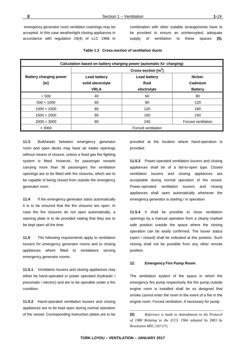
E. Requirements for Particular Spaces 1. Accommodation Spaces
As far as applicable, national requirements should be
observed concerning primary data of air condition
system and air change rates.
TÜRK LOYDU – VENTILATION – JANUARY 2017
1-14 Section 1 – Ventilation E
2. Galleys
2.1 Where they pass through accommodation
spaces or spaces containing combustible materials, the
exhaust ducts from galley ranges shall be constructed
of insulated "A" class divisions. Each exhaust duct shall
be fitted with:
- a grease trap readily removable for cleaning
- a fire damper located in the lower end of the
duct and in addition, a fire damper in the upper
end of the duct
- arrangements, operable from within the galley
near exit, for shutting off the exhaust fan
- fixed means for extinguishing a fire within the
duct are to be provided on all cargo ships and
passenger vessels carrying not more than 36
passengers, where the ducts pass through
accommodation spaces or spaces containing
combustible materials, see Chapter 4,
Machinery Rules, Section 12, M
2.2 For passenger vessels carrying more than 36
passengers see I.3.3.2. 3. Control Stations
3.1 Such measures as are practicable shall be
taken in respect of control stations outside machinery
spaces in order to ensure that ventilation, visibility and
freedom from smoke are maintained, so that in the
event of fire the machinery and equipment contained
therein may be supervised and continue to function
effectively.
In case a control station is served by a common
ventilation system, which serves also other spaces,
effective local closing arrangements shall be provided.
Effective local closing arrangements mean that the
provided ventilation systems shall be fitted with fire
dampers or smoke dampers which could be closed
easily within the control station in order to maintain the
absence of smoke in the event of fire.
3.2 Alternative and separate means of air supply
shall be provided; air inlets of the two sources of supply
shall be so disposed that the risk of both inlets drawing
in smoke simultaneously is minimized.
Such requirements need not be applied to control
stations situated on, and opening on to, an open deck
and where local closing arrangements would be equally
effective.
Alternative and separate means of air supply may be
provided also by combination of a mechanical supply
duct and a natural exhaust duct or vice versa provided
that the fan is reversible. 4. Paint Stores and Flammable Liquid Lockers
4.1 Paint stores and flammable liquid lockers are
to be provided with ventilation arrangements which are
separate from other ventilation systems. 4.2 The ventilation system shall be capable of effecting at least 10 changes of air per hour. The ducts are to be arranged such that both vapours lighter than air and vapours heavier than air can be removed. 4.3 Ventilation outlets or their duct openings shall lead to the open deck area. 4.4 The drives of mechanical ventilators shall be installed outside the rooms and air flow. Otherwise certified safe type drive motors with an explosion protection of at least IIB T3 are to be used. 4.5 The ventilator design shall comply with item D.6. 4.6 Concerning paint stores and flammable liquid lockers see Electric Rules, Section 1, K.3.5. 5. Machinery Space Ventilation 5.1 The ventilation systems for machinery spaces of category A shall be separated from the ventilation systems serving other spaces and shall be in general of the supply type. Other modes of operation may be applied upon special approval. 5.2 Machinery spaces of category A shall be adequately ventilated so as to ensure that when machinery or boilers therein are operating at full power
TÜRK LOYDU – VENTILATION – JANUARY 2017

E Section 1 – Ventilation 1-15
in all weather conditions including heavy weather, an
adequate supply of air is maintained to the spaces for
the safety and comfort of personnel and the operation of
the machinery. Any other machinery space shall be
adequately ventilated appropriate for the purpose of that
machinery space.
5.3 In general, ventilators necessary to
continuously supply the machinery space shall have
coamings of sufficient height to comply with LLC 1966
as amended 1988, Regulation 19(3), without having to
fit weathertight closing appliances (see also D.3.2).
However, where due to ship size and arrangement this
is not practicable, lesser heights for machinery space
coamings, fitted with weathertight closing appliances in
accordance with LLC 1966 as amended 1988,
Regulation 19(4), may be permitted by the
Administration in combination with other suitable
arrangements to ensure an uninterrupted, adequate
supply of ventilation to these spaces (see, Part A,
Chapter 1, Section 16, E.2.4). The machinery spaces
are those defined in SOLAS Regulation II- 1/Reg. 3.16
5.4 The positions of air inlets and air outlets are to
be such as to prevent short-circuiting of air.
5.5 In general the shipboard machinery, equipment
and appliances in machinery spaces are to be designed
for continuous operation at maximum engine room air
temperature as required in the Chapter 4 - Machinery
Rules, Section 1, C
5.6 For the determination of the ventilation
capacity the heat radiation of the equipment in the
space and the required combustion air are to be
considered.
5.7 The capacity and arrangement of ventilation
systems/ ducts is to ensure that accumulation of oil
vapour is avoided under normal conditions.
Note
The capacity requirements mentioned in 5.5, 5.6 and 5.7 are
in general deemed to be met by using the calculations as per
ISO Standard 8861 in the latest version.
5.8 The number of ventilation inlets, ventilators
and exhaust openings in funnels shall be kept to a
minimum, consistent with the needs of ventilation and
the proper and safe working of the ship.
5.9 Suitable arrangements shall be made to permit
the release of smoke in the event of fire (see D.7.3.3).
5.10 Further requirements for control of fans and
fire closures are stipulated in D.7.2 and D.7.3.3.
For application and design of fire closures see D.4.1.
5.11 Air ducts close to electrical switchboards must
be so installed and fitted with drains, where necessary,
that condensed water cannot enter the electrical
installation.
5.12 In case that a gas fire-extinguishing system is
provided for the machinery space it is recommended,
that one of the engine room supply fans should be of
reversible type and supplied from the emergency source
of power supply to enable extraction of fire extinguishing
gases, should the need arise.
5.13 Power driven fire closures for engine rooms
containing combustion engines shall not close
automatically in case of loss of energy (fail safe type)
unless an uninterrupted, adequate air supply to the
engine room can be maintained. This requirement is
deemed to be met if e.g. a sufficient number of fire
closures at air inlets and/or air outlets are of manual
operated type. For a pneumatically operated system for
fail safe type fire closures, the air supply may be from
one air receiver located outside the machinery space
with separated piping from air receiver to the fire
closures. For arrangement of air receiver the Chapter 4
- Machinery Rules, Section 16, D.6.5 are to be used
analogously. 6. Electrical Machines
6.1 If external forced ventilation for electrical
machines is fitted with air ducts leading to the upper
deck, the motors driving these ventilators shall be
provided with an emergency disconnecting switch
outside the engine room.
6.2 A failure of external forced ventilation shall
cause an alarm.
TÜRK LOYDU – VENTILATION – JANUARY 2017

1-16 Section 1 – Ventilation E
6.3 Ventilation ducts shall comply with regulation
D.5.7.
7. CO2 Rooms
7.1 Cylinder rooms are to be provided with
adequate ventilation.
7.2 Spaces where access from the open deck is
not provided or which are located below the open deck
are to be fitted with mechanical exhaust ventilation of
not less than 6 air changes per hour.
7.3 The exhaust duct is to be led to the bottom of
the space.
7.4 Other spaces are not to be connected to this
ventilation system.
8. Refrigerating Machinery Rooms 8.1 Refrigerating machinery spaces shall be
provided with a suitably arranged forced ventilation
system. In case of group 1 refrigerants, at least the
exhaust air is to be conveyed into the open air
independently of other space ventilation ducting. The
inlet ducting shall not be connected to the ventilation
system serving the accommodation spaces.
8.2 In case of group 2 refrigerants, e.g. ammonia,
the ventilation of refrigerating machinery spaces shall
be independent from ventilation systems of other ship
spaces. The ventilation system is to be of exhaust type.
8.3 Within the ship, the exhaust air ducts of fans
serving refrigerating machinery spaces are to be
gastight. The exhaust air shall be conveyed in such a
way as to prevent gas ingress into other ship spaces.
8.4 Provision shall be made for starting and
stopping the fans of refrigerating machinery spaces
from outside the spaces in question. The switches are
to be clearly marked.
8.5 The rating of forced ventilation systems is
subjected the following rules:
- For refrigerating machinery spaces with group
1 refrigerants, forced ventilation shall ensure at
least 30 air changes per hour.
- For refrigerating machinery spaces in with
group 2 refrigerants, e.g. ammonia, the
minimum capacity of the fan shall be
determined by the formula:
In the above formula:
V = Capacity of fan [m3/h]
m = Charge of refrigerant in system [kg]
However, the number of air changes per hour shall not
be less than 40.
Where refrigeration systems using ammonia are
installed in rooms equipped with an effective sprinkler
system, the minimum required capacity of the fans
indicated above may be reduced by 20 %.
9. Spaces Containing Batteries 9.1 General requirements
All battery-installations, except for gastight batteries, in
rooms, cabinets and containers shall be constructed
and ventilated in such a way as to prevent the
accumulation of ignitable gas mixtures. Gastight NiCd-,
NiMH- or Li- batteries need not be ventilated.
9.2 Batteries installed in switchboards with charging power up to 0.2 kW Lead batteries with a charging power up to 0.2 kW may be installed in switchboards without separation to switchgear and without any additional ventilation, if: - the batteries are valve regulated (VRLA),
provided with solid electrolyte - the battery cases are not closed completely (IP
2X is suitable) - the charger is regulated automatically by an IU-
controller with a maximum continuous
3 2m60V ⋅=
TÜRK LOYDU – VENTILATION – JANUARY 2017

E Section 1 – Ventilation 1-17
- Charging voltage of 2.3 V/cell and rated power of the charger is limited to 0.2 kW
9.3 Ventilated spaces with battery charging power up to 2 kW Batteries may be installed in ventilated cabinets and containers arranged in ventilated spaces (excepted rooms mentioned in the Chapter 5 – Electric Rules, Section 2, C.1.1)
The unenclosed installation (IP 12) in well ventilated
positions in machinery spaces is permitted.
Otherwise batteries shall be installed in ventilated
battery cabinets or containers.
The charging power P [W] for automatic IU-charging
shall be calculated as follows:
P = U ⋅ Ι
U = Rated battery voltage [V]
Ι = Charging current [A]
For Pb-batteries For Ni-Cd batteries k = Battery capacity [Ah] The gassing voltage shall not be exceeded. If several
battery sets would be used, the sum of charging power
has to be calculated.
The room free air volume V [m3] and the air quantity Q
[m3/h] shall be calculated depending on battery size as
follows:
V = 2,5 ⋅ Q
Q = f ⋅ n = Number of battery-cells in series connection
f = 0,03 for lead batteries with solid electrolyte
= 0,11 for batteries with fluid electrolyte
If several battery sets would be installed in one room,
the sum of air quantity shall be calculated.
Where the room volume or the ventilation is not
sufficient, enclosed battery cabinets or containers with
natural ventilation into suitable rooms or areas shall be
used.
The air ducts for natural ventilation shall have a cross-
section A [cm2] as follows, assuming an air speed of 0.5
m/s:
A = 5,6 ⋅ Q
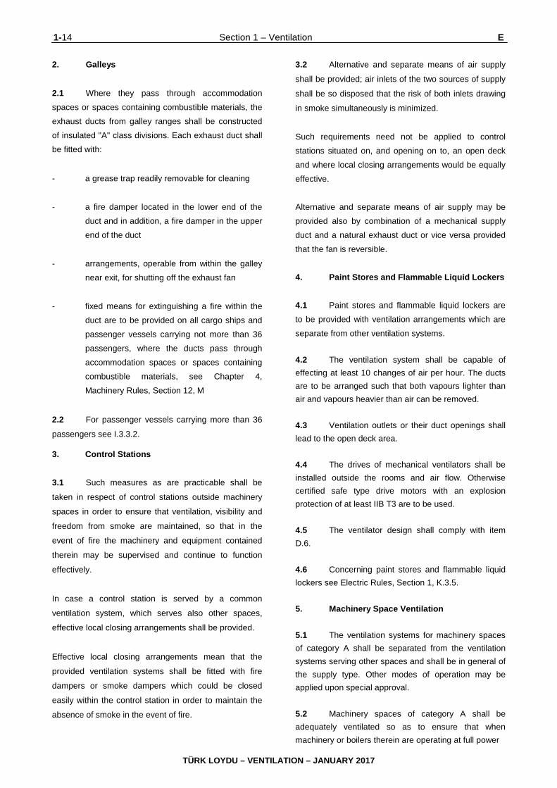
The required minimum cross-sections of ventilation
ducts are shown in Table 1.3.
Small air ducts and dimensions of air inlet and outlet
openings shall be calculated based on an air speed
lower than 0.5 m/s. 9.4 Ventilated rooms with battery charging power more than 2 kW
Batteries exceeding charging power of 2 kW shall be
installed in closed cabinets, containers or battery rooms
forced ventilated to open deck area. Lead batteries up
to 3 kW may be ventilated by natural means.
Battery Rooms shall be arranged according to Chapter
5 – Electric Rules, Section 2, C.3.
9.5 Ventilation requirements
Ventilation inlet and outlet openings shall be so
arranged to ensure that fresh air flows over the surface
of the storage battery.
The air inlet openings shall be arranged below and air
outlet openings shall be arranged above.
If batteries are installed in several floors, the free
distance between them shall be at least 50 mm.
Devices which obstruct the free passage of air, e.g. fire
dampers and safety screens, shall not be mounted in
the ventilation inlet and outlet ducts of battery-rooms. If
necessary, weathertight closures are to be fitted.
100
k8 ⋅=
100
k16 ⋅=
n4
I⋅
TÜRK LOYDU – VENTILATION – JANUARY 2017

1-18 Section 1 – Ventilation E
Air ducts for natural ventilation shall lead to the open
deck directly. Openings shall be at least 0.9 m above
the cupboard/ boxes. The inclination of air ducts shall
not exceed 45° from vertical.
Battery room ventilators are to be fitted with a means of
closing whenever:
- The battery room does not open directly onto
an exposed deck, or
- The ventilation opening for the battery room is
required to be fitted with a closing device
according to the Load Line Convention (i.e. the
height of the open ing does not extend to more
than 4.5 m (14.8 feet) above the deck for
position 1 or to more than 2.3 m (7.5 feet)
above the deck in position 2), or
- The battery room is fitted with a fixed gas fire
extinguishing system.
Where a battery room ventilator is fitted with a closing
device, then a warning notice stating, for example “This
closing device is to be kept open and only closed in the
event of fire or other emergency – EXPLOSIVE GAS”, is
to be provided at the closing device to mitigate the
possibility of inadvertent closing.
9.6 Forced ventilation
If natural ventilation is not sufficient or required cross-
sections of ducts according to Table 1.3 are to big,
forced ventilation shall be provided.
The air quantity Q shall be calculated according to 9.3.
The air speed shall not exceed 4 m/s.
Where storage batteries are charged automatically, with
automatic start of the fan at the beginning of the
charging, arrangements must be made for the
ventilation to continue for at least 1 h after completion of
charging.
Wherever possible, forced ventilation exhaust fans shall
be used. The fan motors must be either certified safe
type with a degree of protection IIC T1 and resistant to
electrolyte or, preferably, located outside of the
endangered area.
Fans are to be of non-sparking construction according
to D.6
The ventilation systems shall be independent of the
ventilation systems serving other rooms.
Air ducts for forced ventilation shall be resistant to
electrolyte and shall lead to the open deck.
10. Separator Spaces 10.1 Where fuel oil purifiers for heated fuel oil are
installed in a separate enclosed space an independent
mechanical ventilation system (supply and exhaust air)
is to be provided. This ventilation system shall be so
arranged that gas/air mixtures or vapours cannot enter
into other parts of the engine room. A ventilation system
ensuring equivalent separation from the engine room
ventilation system, e.g. by means of locally controlled
fire closures, may be accepted. For the height of
ventilation openings E.5.3 is to be observed.
10.2 Where fuel oil purifiers for heated fuel oil are
installed in a space open to the engine room a
mechanical exhaust ventilation system is to be provided
ensuring that gas/air mixtures or vapours cannot enter
into other parts of the engine room.
10.3 For the separator spaces under 10.1 and 10.2
a specific capacity rate of 30 air changes per hour is
deemed to be sufficient. Higher air rates may be
required due to heat generation within the space.
11. Emergency Generator Rooms
11.1 The ventilation system serving the emergency
generator room has to ensure a sufficient supply of
combustion and cooling air for the equipment installed.
11.2 In general, ventilators necessary to immediately supply the emergency generator room must have coamings which comply with regulation 19(3) of LLC 1966, without weathertight closing appliances, see also D.3.2. However, where due to vessels size and arrangement this is not practicable, lesser heights for
TÜRK LOYDU – VENTILATION – JANUARY 2017
E Section 1 – Ventilation 1-19
emergency generator room ventilator coamings may be accepted. In this case weathertight closing appliances in accordance with regulation 19(4) of LLC 1966 in
combination with other suitable arrangements have to be provided to ensure an uninterrupted, adequate supply of ventilation to these spaces (5).
Table 1.3 Cross-section of ventilation ducts
Calculation based on battery charging power (automatic IU- charging)
Battery charging power [w]
Cross-section [m2] Lead battery
solid electrolyte VRLA
Lead battery fluid
electrolyte
Nickel- Cadmium
Battery
< 500 40 60 80
500 < 1000 60 80 120
1000 < 1500 80 120 180
1500 < 2000 80 160 240
2000 < 3000 80 240 Forced ventilation
> 3000 Forced ventilation
11.3 Bulkheads between emergency generator
room and open decks may have air intake openings
without means of closure, unless a fixed gas fire fighting
system is fitted. However, for passenger vessels
carrying more than 36 passengers the ventilation
openings are to be fitted with fire closures, which are to
be capable of being closed from outside the emergency
generator room.
11.4 If the emergency generator starts automatically
it is to be ensured that the fire closures are open. In
case the fire closures do not open automatically, a
warning plate is to be provided stating that they are to
be kept open all the time.
11.5 The following requirements apply to ventilation
louvers for emergency generator rooms and to closing
appliances where fitted to ventalators serving
emergency generator rooms:
11.5.1 Ventilation louvers and closing appliances may
either be hand-operated or power operated (hydraulic /
pneumatic / electric) and are to be operable under a fire
condition.
11.5.2 Hand-operated ventilation louvers and closing
appliances are to be kept open during normal operation
of the vessel. Corresponding instruction plates are to be
provided at the location where hand-operation is
provided.
11.5.3 Power-operated ventilation louvers and closing
appliances shall be of a fail-to-open type. Closed
ventilation louvers and closing appliances are
acceptable during normal operation of the vessel.
Power-operated ventilation louvers and closing
appliances shall open automatically whenever the
emergency generator is starting / in operation.
11.5.4 It shall be possible to close ventilation
openings by a manual operation from a clearly marked
safe position outside the space where the closing
operation can be easily confirmed. The louver status
(open / closed) shall be indicated at this position. Such
closing shall not be possible from any other remote
position.
12. Emergency Fire Pump Room
The ventilation system of the space in which the
emergency fire pump respectively the fire pump outside
engine room is installed shall be so designed that
smoke cannot enter the room in the event of a fire in the
engine room. Forced ventilation, if necessary for pump
(5) Reference is made to Amendments to the Protocol of 1988 Relating to the ICCL 1966 adopted by IMO by Resolution MSC.143 (77)
TÜRK LOYDU – VENTILATION – JANUARY 2017

1-20 Section 1 – Ventilation E,F
operation, is to be connected to the emergency power
supply. If continuously air supply is needed for operation
of emergency fire pump than the height of ventilation
openings has to be in accordance with E.5.3.
13. Pipe Tunnels 13.1 Pipe tunnels are to be at least naturally
ventilated.
13.2 If the pipe tunnels are to be entered via doors
or hatches for operating (e.g. for normal operation of valves or reading of measuring instruments) a
mechanical ventilation shall be provided.
13.3 If the pipe tunnels are entered from the engine
room the engine room ventilation system may be
accepted as sufficient means of mechanical ventilation.
13.4 Pipe tunnels containing ducts or pipes with
flanges, valves or pumps and open ends to hazardous
areas requiring explosion proof equipment, belonging to
the extended hazardous areas (zone 2), see F.2 These
areas are considered safe if they are ventilated with at
least 6 changes of air per hour. Should the ventilation
fail, this shall be announced optically and audibly and
the equipment not permitted for the extended hazardous
area shall be switched off.
14. Thruster Rooms
Thruster rooms are to be provided with suitable
ventilation so as to allow simultaneously crew
attendance and thruster machinery operation at rated
power for the intended period of time. 15. Oxygen-acetylene Storage Rooms 15.1 Gas cylinder storage rooms are to be fitted with ventilation systems capable of providing at least 6 air changes per hour based on the gross volume of the room. The ventilation system is to be independent of ventilation systems of other spaces. The fans are to be of certified safe type IIC T2 and of the non-sparking construction, see D.6. 15.2 It is to be observed that a room temperature of 40 °C will not be exceeded.
15.3 If gas cylinders are stored in cabinets, openings for natural ventilation are to be provided in the upper and the lower part. 16. Storage Places of Gas Bottles for Domestic Purposes The requirements as per item 15 apply. 17. Helicopter Refuelling and Hangar Facilities Enclosed hangar facilities or enclosed spaces containing refuelling installations shall be provided with mechanical ventilation, as required for closed ro-ro spaces of cargo ships in accordance with H. F. Ventilation Requirements for the Carriage of Dangerous Goods 1. Zone 1 (Hazardous Area) 1.1 Areas in which a dangerous gas/air mixture,
dangerous vapours or a dangerous quantity and
concentration of dust are liable to occur from time to
time are defined to be areas subject to explosion hazard
and are defined to be Zone 1.
1.2 Zone 1-areas are: - Closed cargo spaces intended for carriage of
solid goods in bulk which may develop dangerous dust
- Closed cargo spaces and closed or open ro-ro
cargo spaces, intended for carriage of explosive substances in packaged form, flammable liquids with a flash point ≤ 23 °C in packaged form, flammable gases and highly dangerous bulk cargoes which under certain conditions develop a potentially explosive gaseous atmosphere,
- Enclosed or semi-enclosed rooms with non-
closable direct openings to zone 1 areas - Ventilation ducts for zone 1-areas - Areas on open deck or semi-enclosed spaces
on open deck within 1.5 m around ventilation openings of ventilation ducts for zone 1-areas.
TÜRK LOYDU – VENTILATION – JANUARY 2017

F Section 1 – Ventilation 1-21
1.3 Requirement concerning with the protection against explosion in this zone are given in Tables 1.4 and 1.5. 1.4 Concerning further details and installation of electrical equipment and cables see Chapter 5 – Electric Rules, Section 17. 2. Zone 2 (Extended hazardous area) 2.1 Areas in which a dangerous gas/air mixture, dangerous vapours or a dangerous quantity and concentration of dust are liable to occur only rarely, and then only for a brief period, are defined to be Zone 2.
2.2 Zone 2-areas are:
- Areas which can be separated by gastight
doors from zone 1-areas mentioned in F.1.2,
items 1 to 4
- Enclosed spaces like bilge pump rooms or pipe
tunnels containing ducts or pipes with flanges,
valves or pumps and open ends to hazardous
areas if they are ventilated less than 6 changes
per hour
- Areas of 1.5 m surrounding zone 1-areas
mentioned in F.1.2, last item.
2.3 Concerning further details and installation of
electrical equipment and cables see Chapter 5 –
Electrical Installation Rules, Section 17.
3. Cargo Holds 3.1 General 3.1.1 Cargo hold ventilating systems are to be
separated from the ventilation systems serving other
spaces.
3.1.2 If cargo holds are subdivided for reasons of
stability, freeboard or fire protection (e.g. separate
flooding with CO2) this has to be taken into account for
the design of the ventilation systems.
3.1.3 Air ducts and components of ventilation
systems are to be so installed that they are protected
from damage.
3.1.4 For the types of protection generally to be
applied for ventilating systems and the associated
electrical equipment, see Chapter 5 – Electrical
Installation Rules, Section 1, Table 1.9.
4. Dangerous Goods in Packaged Form
4.1 The requirements on the capacity of the
ventilation system, the certified safe type of electrical
explosion protection, the electrical protection and
mechanical design are summarised in the Machinery
Rules – Chapter 4, Section 18, Table 18.10a to 18.10e
and are related to the requirements indicated in SOLAS,
Chapter II-2, Regulation 19.
4.2 If mechanical ventilation is required,
independent exhaust ventilation is to be provided for the
removal of gases and vapours from the upper and lower
part of the cargo space. This requirement is considered
to be met if the ducting is arranged such that
approximately 1/3 of the air volume is removed from the
upper part and 2/3 from the lower part. The position of
air inlets and air outlets shall be such as to prevent
short circuiting of the air. Interconnection of the hold
atmosphere with other spaces is not permitted.
4.3 If fans of electrical explosion protection type
are required, the fan openings on deck are to be fitted
with fixed protective screens with mesh size not
exceeding 13 mm.
4.4 The fans of electrical explosion protection type
must be of non-sparking design, see D.6.2 and D.6.3.
4.5 For the area around ventilation openings
requiring explosion protection, see 1. and 2.
4.6 If adjacent spaces are not separated from
cargo spaces by gastight bulkheads or decks, then they
should be considered as part of the enclosed cargo
space and the ventilation requirements should apply to
the adjacent space as for the enclosed cargo space
itself.
TÜRK LOYDU – VENTILATION – JANUARY 2017

1-22 Section 1 – Ventilation F,G,H
4.7 For open top container holds the mechanical
ventilation is interpreted to be required only for the lower
part of the cargo hold for which purpose ducting is
required.
5. Solid Dangerous Goods in Bulk and Materials Hazardous Only in Bulk
5.1 The requirements on the capacity of the
ventilation system, the certified safe type of electrical
explosion protection, the electrical protection and
mechanical design are summarised in the Machinery
Rules – Chapter 4, Section 18, Table 18.11 and are
related to the requirements indicated in SOLAS,
Chapter II-2, Regulation 19 and the International
Maritime Solid Bulk Cargoes Code (IMSBC Code).
5.2 If mechanical or natural ventilation is required
the ducting is to be arranged such that the space above
the cargo can be ventilated and that exchange of air
from outside to inside the entire cargo space is
provided. The position of air inlets and air outlets shall
be such as to prevent short circuiting of the air.
Interconnection of the hold atmosphere with other
spaces is not permitted.
5.3 If mechanical ventilation required portable fans
may be used instead of fixed ones. If so, suitable
arrangements for securing the fans safely are to be
provided. Electrical connections are to be fixed and
expertly laid for the duration of the installation. Details
are to be submitted to TL for approval.
5.4 If continuous ventilation is required a ventilation system which incorporates at least two powered fans with a capacity of at least three air changes per hour each based on the empty cargo hold is to be provided. The ventilation openings shall comply with the requirements of the Load Line Convention, for openings not fitted with means of closure. According to ICLL, Regulation 19(3) the openings shall be arranged at least 4.50 m above deck in position 1 and at least 2.30 m above deck in position 2. Note: This does not prohibit ventilators from being fitted with a means of closure as required for fire protection purposes under SOLAS, Chapter II-2, Regulation 5.2.1.1.
5.5 If fans of electrical explosion protection type are required, the fan openings on deck are to be fitted with fixed protective screens with mesh size not exceeding 13 mm. 5.6 The fans of electrical explosion protection type must be of non-sparking design, see D.6.2 and D.6.3 5.7 For the area around ventilation openings requiring explosion protection see F.1 and F.2. 5.8 For cargoes emitting toxic gases or vapours the ventilation outlets shall be arranged away from living quarters on or under deck.
5.9 If adjacent spaces are not separated from
cargo spaces by gastight bulkheads or decks, then they
should be considered as part of the enclosed cargo
space and the ventilation requirements should apply to
the adjacent space as for the enclosed cargo space
itself.
G. Refrigerated Containers
1. Refer to Annex A, G.
2. Vessels for which the class notation RCP is
applied for, the requirements of the TL Guidelines for
the Carriage of Refrigerated Containers on Board Ships
are to be complied with.
H. Cargo Spaces for the Carriage of Vehicles with Fuel in their Tanks and Cargo Spaces of Ro-Ro Ships 1. Capacity of Ventilation System
1.1 The cargo spaces for the carriage of vehicles
with fuel in their tanks of cargo ships and cargo spaces
of ro-ro ships are to be provided with forced ventilation
capable of at least 6–10 air changes per hour,
depending on arrangement of electrical equipment. See
Electrical Installation Rules, Section 16.
TÜRK LOYDU – VENTILATION – JANUARY 2017

H Section 1 – Ventilation 1-23
1.2 During periods of loading and unloading an
increased air change rate of 20 air changes per hour is
to be provided (6). 2. Performance and Design of Ventilation Systems
2.1 In cargo ships, ventilation fans shall normally
be run continuously and give at least the number of air
changes required in item 1.1 whenever vehicles are on
board, except where an air quality control system in
accordance with paragraph 2.4 is provided. Where this
is impracticable, they are to be operated for a limited
period daily as weather permits and in any case for a
reasonable period prior to discharge, after which period
the ro-ro or vehicle space shall be proved gas-free.
One or more portable combustible gas detecting
instruments are to be carried on board for this purpose.
2.2 The system shall be entirely separate from
other ventilating systems. Ventilation ducts serving ro-ro
or vehicle spaces shall be capable of being effectively
sealed for each cargo space. The system shall be
capable of being controlled from a position outside such
spaces.
2.3 The ventilation system shall be such as to
prevent air stratification and the formation of air pockets.
2.4 Where an air quality control system is provided
based on the guidelines (7), the ventilation system may
be operated at a decreased number of air changes
and/or a decreased amount of ventilation. This
relaxation does not apply to spaces to which at least ten
air changes per hour is required by Chapter 5 Electrical
Installation Section 16 B.2.1 and spaces subject to item
Chapter 1 Hull Section 21 C.15.1 and Chapter 4
Machinery Section 18 B.12.
(6) Alternatively the required air changes can be
calculated according to Revised design guidelines and
operational recommendations for ventilation systems in ro-ro
cargo spaces (MSC/Circ.1515)
(7) Refer to the Revised design guidelines and operational
recommendations for ventilation systems in ro-ro cargo
spaces (MSC/Circ.1515).
2.5 An independent power ventilation system is to
be provided for the removal of gases and vapours from
the upper and lower part of the cargo space. This
requirement is considered to be met if the ducting is
arranged such that approximately 1/3 of the air volume
is removed from the upper part and 2/3 from the lower
part. Supply ventilation may be natural and be
introduced into the cargo spaces at the top of these
spaces.
2.6 The design of mechanical exhaust ventilators
has to comply with D.6
2.7 A fan failure (monitoring of motor fan switching
devices is sufficient) shall be alarmed on the bridge.
2.8 Inlets for exhaust ducts are to be located within
450 mm above the vehicle deck. Outlets are to be
located in a safe position, having regard to sources of
ignition near the outlets.
2.9 For areas in the vicinity of air openings, see F.1 ad F.2. 3. Closing Appliances and Ducts 3.1 Arrangements shall be provided to permit a rapid shutdown and effective closure of the ventilation system from outside of the space in case of fire, taking into account the weather and sea conditions. Access routes to the controls for closure of the ventilation system permit “a rapid shutdown” and “adequately take into account the weather and sea conditions” if the routes: - Are clearly marked and at least 600 mm clear
width; - Are provided with a single handrail or wire rope
lifeline not less than 10 mm in diameter, supported by stanchions not more than 10 m apart in way of any route which involves traversing a deck exposed to weather; and
- Are fitted with appropriate means of access
(such as ladders or steps) to the closing devices of ventilators located in high positions (i.e. 1.8 m and above).
TÜRK LOYDU – VENTILATION – JANUARY 2017

1-24 Section 1 – Ventilation I
Alternatively, remote closing and position indicator
arrangements from the bridge or a fire control station for
those ventilator closures are acceptable.
3.2 Ventilation ducts, including dampers, shall be
made of steel. Ventilation ducts shall not pass through
machinery spaces of category A unless fire insulated to
A-60 standard.
4. Permanent Openings
Permanent openings in the side plating, the ends or
deckhead of the space shall be so situated that a fire in
the cargo space does not endanger stowage areas and
embarkation stations for survival craft and
accommodation spaces, service spaces and control
stations in superstructures and deckhouses above the
cargo spaces.
5. Electrical Equipment and Cable Installation
Concerning installation of electrical equipment and
cables see Chapter 5 – Electrical Installation Rules,
Section 16. I. Additional Rules for Passenger Ship 1. General
1.1 Application
These rules are applied in addition to the rules of D ÷ E.
1.2 Means of control
All controls indicated in D.7.2 as well as means of
control for permitting release of smoke from machinery
spaces are to be located at one control position or
grouped in as few positions as possible. Such positions
are to have a safe access from the open deck.
1.3 Ventilation ducts
Where in a passenger ship it is necessary that a
ventilation duct passes through a main vertical zone
division, a fail-safe automatic closing fire damper shall
be fitted adjacent to the division. The damper shall also
be capable of being manually closed from each side of
the division. The operating position shall be readily
accessible and be marked in red light-reflecting colour.
The duct between the division and the damper shall be
of steel or other equivalent material and, if necessary,
insulated to the same standard as the penetrated
division. The damper shall be fitted on at least one side
of the division with a visible indicator showing whether
the damper is in the open position. 1.4 Smoke extraction systems in atriums of passenger ships Public spaces within a single main vertical zone spanning three or more open decks (Atriums) and contain combustibles such as furniture and enclosed spaces such as shops, offices and restaurants shall be equipped with a smoke extraction system. The smoke extraction system shall be activated by the required smoke detection system and be capable of manual control. The fans shall be sized such that the entire volume within the space can be exhausted in 10 min or less (8). 2. Additional Rules for Passenger Vessels Carrying not More than 36 Passengers 2.1 Cargo spaces for the carriage of vehicles with fuel in their tanks and cargo spaces of ro-ro ships
2.1.1 Capacity of ventilation system
2.1.1.1 The closed ro-ro and vehicle spaces of passenger ships carrying not more than 36 passengers are to be provided with forced ventilation capable of at least 6 air changes per hour, if the electrical equipment is of certified safe type in the entire space, or at least 10 air changes per hour, if the electrical equipment is of certified safe type up to a height of 450 mm above the deck (see Chapter 5 – Electric Rules, Section 16).
2.1.1.2 Special category spaces are to be equipped with forced ventilation capable of effecting at least 10 air changes per hour. Special category spaces are closed vehicle decks on passenger ships to which the passengers have access.
2.1.1.3 During loading and unloading periods 20 air changes per hour is to be provided (9). (8) See MSC / Circ. 1034. (9) Alternatively, the air changes can be calculated according to Revised design guidelines and operational recommendations for ventilation systems in ro-ro cargo spaces (MSC/Circ.1515)
TÜRK LOYDU – VENTILATION – JANUARY 2017

I Section 1 – Ventilation 1-25
2.1.2 Performance and design of ventilation systems 2.1.2.1 In passenger ships, the power ventilation system shall be separate from other ventilation systems. The power ventilation system shall be operatedto give at least the number of air changes required in item 2.1.1.1 at all times when vehicles are in such spaces, except where an air quality control system in accordance with item 2.1.2.2 is provided. Ventilation ducts serving such cargo spaces capable of being effectively sealed shall be separated for each such space. The system shall be capable of being controlled from a position outside such spaces. 2.1.2.2 Where an air quality control system is provided based on the guidelines (7), the ventilation system may be operated at a decreased number of air changes and/or a decreased amount of ventilation. This relaxation does not apply to spaces to which at least ten air changes per hour is required by Chapter 5 Electrical Installation Section 16 B.1.1 and spaces subject to item Chapter 1 Hull Section 21 B.21.1 and Chapter 4 Machinery Section 18 B.12. 2.1.2.3 On passenger ships, a fan failure (monitoring of motor fan switching devices is sufficient) or failure related to the number of air changes specified for vehicle decks and holds shall be alarmed on the bridge. 2.1.3 Closing appliances and ducts Ventilation ducts, including dampers shall be made of steel. In passenger ships, ventilation ducts that pass through other horizontal zones or machinery spaces shall be "A-60" class steel ducts constructed in accordance with D.5.3. 2.2 Ro-ro cargo spaces in passenger ships not intended for the carriage of vehicles with fuel in their tanks 2.2.1 For closed ro-ro cargo spaces which are not intended for the carriage of vehicles with fuel in their tanks nor are special category spaces the requirements as per H and I.2.1, with the exception of H.2.5, H.2.7
and H.5 apply.
2.2.2 For open ro-ro cargo spaces which are not
intended for the carriage of vehicles with fuel in their
tanks nor are special category spaces the requirements
applicable to a conventional cargo space shall be
observed with the exception that a sample extraction
smoke detection system is not permitted.
3. Rules for Passenger Vessels Carrying more than 36 Passengers
3.1 In general, the ventilation fans shall be so
disposed that the ducts reaching the various spaces
remain within the main vertical zone.
3.1.1 Where ventilation systems penetrate decks,
precautions shall be taken, in addition to those relating
to the fire integrity of the deck, see D.5.7 to reduce the
likelihood of smoke and hot gases passing from one
between deck space to another through the system. In
addition to insulation requirements contained in D.5
vertical ducts shall, if necessary, be insulated as
required by the appropriate tables.
3.2 Means of control 3.2.1 All power ventilation, except machinery and cargo spaces ventilation and any alternative systems which may be required under D.7.3.2, shall be fitted with controls so grouped that all fans may be stopped from either of two positions which shall be situated as far apart as practicable. Controls provided for the power ventilation serving machinery spaces shall also be grouped so as to be operable from two positions, one of which shall be outside such spaces. Fans serving power ventilation systems to cargo spaces shall be capable of being stopped from a safe position outside such spaces. 3.2.2 Controls for shutting down the ventilation fans shall be centralized in a continuously manned central control station. The ventilation fans shall be capable of reactivation by the crew at this location, whereby the control panels shall be capable of indicating closed or off status of fans. 3.3 Ventilation ducts 3.3.1 Except in cargo spaces, ventilation ducts shall be constructed of the following materials:
3.3.1.1 Ducts not less than 0,075 m2 in sectional area
and all vertical ducts serving more than a single tween
deck space shall be constructed of steel or other
equivalent material.
TÜRK LOYDU – VENTILATION – JANUARY 2017

1-26 Section 1 – Ventilation I
3.3.1.2 Ducts less than 0,075 m2 in sectional area
other than vertical ducts referred to in 3.3.1.1 shall be
constructed of steel or other equivalent material. Where
such ducts penetrate "A" or "B" Class divisions due
regard shall be given to ensuring the fire integrity of the
division.
3.3.2 Exhaust ducts from galley ranges in which grease or fat is likely to accumulate shall meet the requirements as mentioned in D.5.3.5 and shall be fitted with: - A grease trap readily removable for cleaning
unless an alternative approved grease removal system is fitted
- A fire damper located in the lower end of the
duct which is automatically and remotely operated, and in addition a remotely operated fire damper located in the upper end of the duct
- A fixed means for extinguishing a fire within the
duct, see also Chapter 4 – Machinery Rules, Section 12
- Remote control arrangements for shutting off
the exhaust fans and supply fans, for operating
the fire dampers mentioned in 3.3.2, item 2 and
for operating the fire-extinguishing system,
which shall be placed in a position close to the
entrance to the galley. Where a multi-branch
system is installed, means shall be provided to
close all branches exhausting through the
same main duct before an extinguishing
medium is released into the system - Suitably located hatches for inspection and
cleaning 3.3.3 Exhaust ducts from ranges for cooking equipment installed on open decks shall conform to paragraph 3.3.2, as applicable, when passing through accommodation spaces or spaces containing combustible materials. 3.3.4 Exhaust ducts from main laundries shall be
fitted with:
- Filters readily removable for cleaning purposes
- A fire damper located in the lower end of the
duct which is automatically and remotely
operated
- Remote control arrangements for shutting off
the exhaust fans and supply fans from within
the space and for operating the fire damper
mentioned in paragraph I.3.3.4, item 2
- Suitably located hatches for inspection and
cleaning
3.3.5 Exhaust ducts shall be provided with suitably
located hatches for inspection and cleaning. The
hatches shall be located near the fire damper.
3.4 Stairway
Stairway enclosures shall be ventilated by an
independent fan and duct system which shall not serve
any other spaces in the ventilation system.
3.5 Cargo spaces for the carriage of vehicles with fuel in their tanks and cargo spaces of ro-ro ships 3.5.1 Capacity of ventilation system 3.5.1.1 The closed ro-ro, vehicle and special category spaces of passenger ships carrying more than 36 passengers are to be provided with forced ventilation capable of effecting at least 10 air changes per hour. 3.5.1.2 During loading and unloading periods an increased air change rate of 20 air changes per hour is to be provided. Alternatively, the air changes can be calculated according to MSC.1/Circ.1515 – Revised design guidelines and operational recommendations for ventilation systems in ro-ro cargo spaces. 3.5.2 Performance and design of ventilation systems 3.5.2.1 In passenger ships, the power ventilation system of the space shall be separate from other ventilation systems and shall be in operation at all times when vehicles are in such spaces. Ventilation ducts serving such cargo spaces capable of being effectively sealed shall be separated for each such space. The system shall be capable of being controlled from a position outside such spaces.
TÜRK LOYDU – VENTILATION – JANUARY 2017

I,J Section 1 – Ventilation 1-27
3.5.2.2 On passenger ships, a fan failure (monitoring
of motor fan switching devices is sufficient) or failure
related to the number of air changes specified for
vehicle decks and holds shall be alarmed on the bridge.
3.5.3 Closing appliances and ducts
Ventilation ducts, including dampers shall be made of
steel. In passenger ships, ventilation ducts that pass
through other horizontal zones or machinery spaces
shall be "A-60" class steel ducts constructed in
accordance with D.5.3.
3.6 Ro-ro cargo spaces in passenger ships not intended for the carriage of vehicles with fuel in their tanks
3.6.1 For closed ro-ro cargo spaces which are not
intended for the carriage of vehicles with fuel in their
tanks nor are special category spaces the requirements
as per H and I.3.5, with the exception of H.2.5 and
H.2.7.
3.6.2 For open ro-ro cargo spaces which are not
intended for the carriage of vehicles with fuel in their
tanks nor are special category spaces the requirements
applicable to a conventional cargo space shall be
observed with the exception that a sample extraction
smoke detection system is not permitted.
J. Special Class Notation AHTS 1. General
The class notation AHTS (Advanced Hatch Tightness
System) stands for a system which provides additional
tightness of cargo hold hatch covers by means of
sealing air while pressurising the cargo hold. Preferably
the system should be used in connection with a cargo
hold air drying system.
2. Documents to be submitted
- General arrangement
- Ventilation arrangement of cargo holds
İncluding AHTS
- Details of weather tight closures of hatch
covers
- Details of fire flaps and demister (mist
eliminators)
- Details of fan layout
- Details of fan control and pressure alarm
system
3. Requirements 3.1 The cargo hold hatch cover sealing system
must be of weather tight design.
3.2 If one fan is shut-down, the number of fans is
to be selected such that the required air capacity may
still be supplied to the cargo hold (e.g. 2 . 100 % or 3 .
50 %).
3.3 The cargo holds are to be pressurised by a
system separate of other cargo hold ventilation
systems.
3.4 The system must be capable of generating an overpressure in the cargo holds of not less than 0,04 bar. 3.5 Each cargo hold is to be provided with an excess flow valve/flap designed for continuous operation. The opening shall be arranged at a height of not less than 4,50 metre above freeboard deck. The excess flow devices are to incorporate fire closures and pressure control facilities operable from outside. The maximum release pressure of the excess flow valves/flaps is not to exceed the set pressure by more than 10 %. 3.6 The maximum excess flow valve/flap and fan air capacities are to be based on the expected maximum amount of leakage air which may flow through the weathertight hatch cover sealings and other cargo hold sealings taking into account sealing maintenance and the overflow device set pressure. 3.7 The fans are to be controlled from the navigation bridge. The operating pressure of each cargo hold equipped with AHTS and the operating current of the fans are to be indicated on the navigation bridge.
TÜRK LOYDU – VENTILATION – JANUARY 2017

1-28 Section 1 – Ventilation J,K,L
3.8 A visual and audible individual high pressure
and low pressure alarm for each cargo hold equipped
with AHTS is to be provided on the navigation bridge.
3.9 The lower edge of the suction air openings of
the over pressure fans must end at a height of not less
than 4,50 metre above the freeboard deck. The suction
air openings are to be provided with fire closures and
effective demisters.
3.10 Doors and hatches to and from the cargo
spaces under pressure are to be provided with warning
labels stating that the overpressure fans are to be
shutdown before opening. 3.11 Doors and hatches to the cargo spaces when under pressure must be provided with locking arrangements which shall be under the control of the responsible ship's officer. 3.12 Emergency stop of the overpressure fans at the doors/hatches of cargo spaces under pressure is to be provided which gives audible alarm on the navigation bridge. 3.13 A written statement of the manufacturer of the hatch covers is be available before granting the class notation AHTS confirming that the higher loads during operation under pressure as per 3.4, considering as well the pressure tolerance mentioned under 3.5, had been considered.
4. Testing Following the plan approval a successful functional test in the presence of a TL-Surveyor has to be carried out. K. Additional Rules for Tankers For the design and construction of ventilation system for tankers the following rules are to be observed in addition:Tankers Chapter 4 – Machinery Rules, Section 20- Tankers Oil Recovery Chapter 12 – Oil Recovery Vessels Vessels Liquefied Gas Chapter 10 – Liquefied Gas Tankers Tankers Section 12 – Mechanical Ventilation in
the Cargo Area Chemical Chapter 8 – Chemical Tankers, Tankers Section 12 - Mechanical Ventilation in
the Cargo Area L. Air Changes per Hour In the following Tables 1.4 to 1.5 the requirements in terms of air changes per hour are listed for various types of ship.
TÜRK LOYDU – VENTILATION – JANUARY 2017

L Section 1 – Ventilation 1-29
Table 1.4 General requirements for all ships
Ventilated space Air changes/hour
Supply air Air changes/hour
Exhaust air Req. no.
Remarks
Paint stores and
flammable liquid lockers 10 E.4
Engine room E.5 as per combustion air and heat radiation requirement, see also ISO 8861 as guidance
CO2 room 6 E.7 Below open deck
Refrigerating machinery room
30 / 40 E.8 Formula
Spaces containing batteries
E.9 Formula
Separator space 30 E.10 increase due to heat radiation possible
Emergency generator room
E.11 as per combustion air and heat radiation requirement
Dangerous goods in packaged form
6
(for certain cargoes) F.4
2 air changes/hour for container cargo spaces
Solid dangerous goods in bulk
6
(for special bulk cargoes)
F.5
Reefer cargo holds G Class notation RCP
Cargo ships: Closed vehicle spaces, closed ro-ro spaces
10 or 6 (acc. to the provided grade of explosion protection
H
increased ventilation capacity (at least 20 air changes/hour) during vehicle roll on/roll off required. Optional proof acc. to IMO MSC.1/Circ.1515 possible
Livestock spaces 20-30 Annex
A,H
Location emergency fire pump
E.12 Clear of smoke
Pipe tunnel E.13 extended dangerous area (zone 2) to be observed
Thruster room E.14 intended time span to observe Oxygen/Acetylen storage room
6 E.15
Storage place of gas bottles for domestic purposes
6 E.16
TÜRK LOYDU – VENTILATION – JANUARY 2017

1-30 Section 1 – Ventilation L
Table 1.5 Special requirements for passenger ships
Ventilated space Air
changes/hour Supply air
Air changes/hour
Exhaust air
Req. no.
Remarks
Passenger ships
(≤ 36 passengers):
Closed vehicle spaces,
closed ro-ro spaces
10 or 6 air
changes/hour acc.
to the provided
grade of explosion
protection
I.2.1
Increased ventilation capacity
(at least 20 air changes/hour) during
vehicle roll on/roll off required.
Optional proof acc. to IMO
MSC.1/Circ.1515 possible.
Passenger ships
(≥ 36 passengers):
Closed vehicle spaces,
closed ro ro spaces
10 I.3.5
Increased ventilation capacity
(at least 20 air changes/hour) during
vehicle roll on/roll off required. Optional
proof acc. to IMO MSC.1/Circ.1515
possible.
Passenger ships:
Special category space: 10
I.2.1
+
I.3.5
Increased ventilation capacity
(at least 20 air changes/hour) during
vehicle roll on/roll off required. Optional
proof acc. to IMO MSC.1/Circ.1515
possible.
TÜRK LOYDU – VENTILATION – JANUARY 2017

Annex-A Annex A-1
TÜRK LOYDU – VENTILATION – JANUARY 2017
ANNEX A
RECOMMENDATIONS
Page
A. General Arrangement ......................................................................................................................................................... 1- 2
B. Testing ................................................................................................................................................................................. 1- 2
C. Ventilation Equipment........................................................................................................................................................ 1- 2
D. Machinery Space Ventilation ............................................................................................................................................. 1- 2
E. Cargo Holds ........................................................................................................................................................................ 1- 2
F. Emergency Generator Room .............................................................................................................................................. 1- 2
G. Refrigerated Containers ..................................................................................................................................................... 1- 2
G. Livestock Carrier ................................................................................................................................................................ 1- 2
I. Principal Construction of Duct Penetretion through “A” Class Bulkheads or Decks ..................................................... 1- 3
J. Air Changes per Hour ........................................................................................................................................................ 1- 3

Annex-A-2 Annex A A,B,C,D,E,F,G
TÜRK LOYDU – VENTILATION – JANUARY 2017
A. General Arrangement
Short-circuiting between intakes and exhaust openings should
be prevented.
B. Testing
Where so agreed, measurements of air flow, air temperature,
air humidity or air velocity may be performed after
installation of the systems.
The accuracy of the measurements should be ensured by
suitable measuring instruments.
It is recommended that for the measurements the following
allowances are accepted:
air flow of the unit [m3/h] – 10 % to + 15 %
air flow of spaces [m3/h] – 10 % to + 10 %
air humidity [R.H.] – 10 % to + 15 %
air velocity accom. spaces [m/s] – 0.05 m/s to + 0.05 m/s
air temperature accom. spaces [°C] - 1.5 °C to + 1.5 °C
C. Ventilating Equipment
Ventilating equipment should be designed to keep noise
pollution to a tolerable level.
D. Machinery Space Ventilation
1. A slight overpressure (< 50 Pa) in the machinery
space during normal operation should be ensured.
2. For conventional ventilation systems on seagoing
ships with unrestricted service it is recommended to use the
ISO Standard 8861 in the latest version.
3. The stream of supply air should not be directed
immediately towards hot machine parts, turbine components,
measuring instruments or switchboards.
4. The air should be conducted in such a way as to
avoid local accumulations of heat wherever possible.
5. Power operated fire closures should be capable of
being operated individually for test purposes at site.
6. The areas of the crew's normal watch-keeping
within the engine room should be ventilated to keep a
maximum ambient air temperature of + 45 °C. Workshops
should be provided with direct "cold spot" ventilation with
fresh air. Engine control rooms should be normally air-
conditioned to keep a maximum air temperature of + 28 °C
under the expected heat load and by moderate fresh air
exchange rates. In case of failure of the air condition unit
"direct ventilation" with fresh air to remove the expected heat
should be possible or second independent air condition unit
with sufficient capacity should be provided.
E. Cargo Holds
1. Where the nature of the cargo so requires, every
cargo hold should be adequately ventilated.
2. The position of air inlets and air outlets should be
such as to prevent short circuiting of air.
F. Emergency Generator Room
1. The emergency generator room should be provided
with fire closures even if no gas fire extinguishing system is
installed.
2. If the emergency generator automatically starts the
fire closures should open automatically, if normally closed
fire closures are provided.
G. Refrigerated Containers
1. For unrestricted service range of the vessel the
following values for supply air may be used as guidance:
- Refrigerated containers using air-cooled
condensers:
◦ 3 100 m3/h per TEU
◦ 4 500 m3/h per FEU

G,H,I,J Annex-A Annex A-3
TÜRK LOYDU – VENTILATION – JANUARY 2017
- Refrigerated containers using water-cooled
condensers
◦ 460 m3/h per TEU
◦ 700 m3/h per FEU
In case of restricted services, the capacities for supply air
may be reduced depending on the nature of cargoes and the
shipping routes.
2. Air ducting and air distribution systems should be so
designed as to ensure heat dissipation from container holds
under worst case conditions.
H. Livestock Carrier
1. An enclosed space for the carriage of livestock
should be provided with a mechanical supply ventilation
system of sufficient capacity to change the air of that space in
its entire volume as follows:
- if the minimum clear height of the space is 2.30 m
or more, not less than 20 air changes per hour
- if the minimum clear height of the space is 1.80 m,
not less than 30 air changes per hour
- if the minimum clear height of the space is between
2.30 m and 1.80 m, at a rate proportional to those
specified above.
2. A space for the carriage of livestock that is not
enclosed should be provided with a mechanical ventilation
system according 1, if
- the space, being a structure having an arrangement
of pens on more than one deck level, has a breadth
greater than 20 m; or
- because of a partial enclosure of the space, the
natural ventilation is restricted.
3. A mechanical ventilation system should distribute
air so as to ensure that the whole of each livestock space is
efficiently ventilated. Exhaust air outlets should be sited clear
of the accommodation.
4. Ventilators serving livestock spaces should remain
open in all weather conditions while livestock are on board.
5. A secondary source of electrical power for the
ventilation system should be provided. It should be capable of
supplying power to ventilation system for a period of three
days in case of a fire or other casualty in the space
containing the main source of electrical power.
6. National requirements, if any, should be observed.
. Principal Construction of Duct Penetration
through "A" Class Bulkheads or Decks
The following Fig. A.1 to A.3 show principal construction
details of duct penetrations.
J. Air Changes per Hour
1. Values of Air Changes per Hour
The following Table A.1 contains air change rates for the
design of ventilation system, which refers to the
empty space.
2. Accommodation Spaces
2.1 Accommodation spaces should be assured of
sufficient air renewal under all conditions of
weather and climate proper to the intended range of service.
2.2 Ventilation systems should be capable of effecting
the changes of air specified in Table A.1.
2.3 Ships navigating in the tropics or similar regions
should be equipped with mechanical ventilation or an air-
conditioning system.
2.4 Air Conditioning and Hot Air Heating Systems
The following conditions apply:
Annex A-4 Annex-A J
TÜRK LOYDU – VENTILATION – JANUARY 2017
Summer (not applicable to hot air heating systems)
Outside air + 35 °C – 70 % relative humidity
Inside Air + 27 °C – 50 % relative humidity
Winter
Outside air – 20 °C
Inside Air + 22 °C
Other assumption may be permitted for winter operation in
certain defined ranges of service.
2.5 Cabins with own sanitary facilities should be
supplied with approximately 10% more incoming air than
extracted from the sanitary space.
2.6 When cooling, the temperature of the supply air
should not be more than 10 °C below the mean room
temperature, and, when heating should not be more than 23 °
C above the mean room temperature.
2.7 The temperature variation within a space should
not more than 2 °C.
2.8 The velocity and direction of the air flow should be
chosen so as to prevent troublesome draughts. Air outlets
should not be located at the head end of bunks.
2.9 Air movements in accommodation areas should not
exceed 0.2 to 0.3 m/s.
2.10 The air velocity through exhaust gratings should
not exceed 5 m/s.
2.11 The exhaust air from pantries and public sanitary
spaces should in general be directly and independently
conducted to the outside atmosphere.
Table A.1 Air change rates
Ventilated space Air changes/hour
Supply air
Air changes/hour
Exhaust air Remarks
Living/sleeping quarters 6 (8) -
Value in brackets valid
for 20 % recirculated air.
Messes, saloons, offices 12 (15) 12 (15)
Hospitals 12 12
Galleys 12+28 (15+25) 40
Pantries 15 (20) 15 (20)
Dry provision rooms 5 (10) 5 (10)
Sanitary rooms 10-15
Laundries 10-20 15-30
Drying rooms 25 30
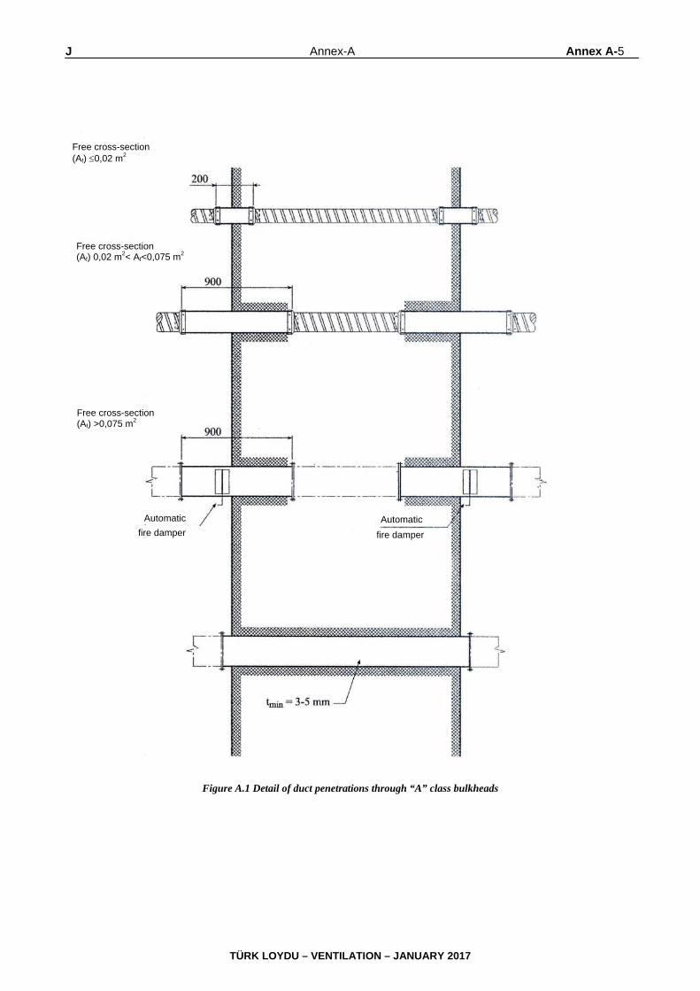
J Annex-A Annex A-5
TÜRK LOYDU – VENTILATION – JANUARY 2017
Figure A.1 Detail of duct penetrations through “A” class bulkheads
Free cross-section (Af) 0,02 m2
Free cross-section (Af) 0,02 m2< Af<0,075 m2
Free cross-section (Af) >0,075 m2
fire damper Automatic Automatic
fire damper

Annex A-6 Annex-A J
TÜRK LOYDU – VENTILATION – JANUARY 2017
Figure A.2 Detail of duct penetrations through “A” class bulkheads or decks with a free cross-section (Af ) 0,02 m2
DeckBulkhead
Steel sleeve
A0-Deck
A0-Bulkhead
SPIRO-DUCT Steel sleeve
SPIRO-DUCT
A15-A60 (insulated)
Deck
Steel sleeve Steel sleeve SPIRO-DUCT
SPIRO-DUCT
A15-A60 - Bulkhead

J Annex-A Annex A-7
TÜRK LOYDU – VENTILATION – JANUARY 2017
Figure A.3 Detail of duct penetrations through “A” class bulkheads or decks free cross-section (Af ): 0,02 m2 < Af < 0,075m2
Bulkhead Deck
Steel sleeve
A0-Bulkhead
A15-A60 – (insulated)
Steel sleeve
Steel sleeve
A15-A60 – (insulated)
(insulated) (insulated)
Steel sleeve
Deck