Embed Size (px)
Citation preview
Highway Surveying Manual Page 15-1 January 2005
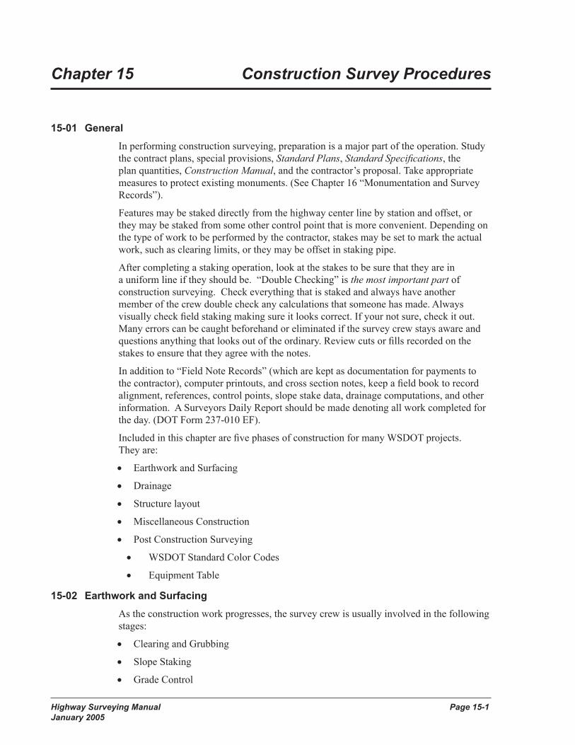
Chapter 15 Construction Survey Procedures
15-01 GeneralIn performing construction surveying, preparation is a major part of the operation. Study the contract plans, special provisions, Standard Plans, Standard Specifications, the plan quantities, Construction Manual, and the contractor’s proposal. Take appropriate measures to protect existing monuments. (See Chapter 16 “Monumentation and Survey Records”).
Features may be staked directly from the highway center line by station and offset, or they may be staked from some other control point that is more convenient. Depending on the type of work to be performed by the contractor, stakes may be set to mark the actual work, such as clearing limits, or they may be offset in staking pipe.
After completing a staking operation, look at the stakes to be sure that they are in a uniform line if they should be. “Double Checking” is the most important part of construction surveying. Check everything that is staked and always have another member of the crew double check any calculations that someone has made. Always visually check field staking making sure it looks correct. If your not sure, check it out. Many errors can be caught beforehand or eliminated if the survey crew stays aware and questions anything that looks out of the ordinary. Review cuts or fills recorded on the stakes to ensure that they agree with the notes.
In addition to “Field Note Records” (which are kept as documentation for payments to the contractor), computer printouts, and cross section notes, keep a field book to record alignment, references, control points, slope stake data, drainage computations, and other information. A Surveyors Daily Report should be made denoting all work completed for the day. (DOT Form 237-010 EF).
Included in this chapter are five phases of construction for many WSDOT projects. They are:
• Earthwork and Surfacing
• Drainage
• Structure layout
• Miscellaneous Construction
• Post Construction Surveying
• WSDOT Standard Color Codes
• Equipment Table
15-02 Earthwork and SurfacingAs the construction work progresses, the survey crew is usually involved in the following stages:
• Clearing and Grubbing
• Slope Staking
• Grade Control
Page 15-2 Highway Surveying Manual January 2005
Construction Survey Procedures
Highway Surveying Manual Page 15-3 January 2005
Construction Survey Procedures
15-02.1 Clearing and GrubbingAfter Aesthetic and Environmental concerns are addressed, Clearing and Grubbing stakes are set to mark the limits of disposal of all unwanted material from the surface (clearing) and underground (grubbing). This prepares the project for other staking and construction activities. See Chapter 2-1 of the Construction Manual.
Use the construction center line as the reference line for setting clearing stakes. Set stakes (lath) at least 4 feet long, marked “Clearing,” at the offset, marking the limits of the area to be cleared. Where slope treatment is to be provided, clearing normally is staked 10 feet beyond the limits of the slope treatment with 5 feet minimum. Do not set grading stakes until clearing and grubbing work is completed. Refer to the Standard Specifications, Section 2-01.
While staking for clearing and grubbing, the party chief prepares a “Field Note Record,” WSDOT Form 422-636EF (Figure 15-1). Complete the heading. In the sketch grid area, show center line, stations, and limits of clearing and grubbing. Include a north arrow. Do not try to draw to scale, as an exaggerated scale makes the note easier to read. Use a straightedge for straight lines. Gaps that require no work and isolated areas that require work should be staked in accordance to the Standard Specifications in Section 2.01.4.
Figure 15-1 Field Notes for Clearing and Grubbing
Page 15-2 Highway Surveying Manual January 2005
Construction Survey Procedures
Highway Surveying Manual Page 15-3 January 2005
Construction Survey Procedures
15-02.2 Slope StakingSlope staking is a trial and error process of finding the point where the slope intercepts the natural ground. This point is referred to as the “catch point” or “slope catch.”
The information needed to set slope stakes is obtained from the contract plans and the computer generated slope stake notes which includes:
• Profile grade elevation.
• Traveled way cross slopes and lane widths.
• Shoulder slopes and widths.
• Side slopes, cut or fill.
• Ditch inslopes, back slopes, and depths.
• Total depth of surfacing materials.
Figure 15-2A Computer Generated Slope Stake Notes Also see Figure 15-2B for an example of hand written slope stake notes.
Page 15-4 Highway Surveying Manual January 2005
Construction Survey Procedures
Highway Surveying Manual Page 15-5 January 2005
Construction Survey Procedures
Figure 15-2B Hand Written Generated Slope Stake NotesThere are various ways to slope stake a project, depending on which method you choose. They are listed as follows:
• Manual Method - Manual slope staking using a rag tape, fiberglass rod and level.
• Conventional Method - Slope staking using a total station and data collector, setting out the offset and distance from the design catches and then manually slope staking from this point.
• Modified Conventional Method - Slope staking using a total station and data collector, using the slope staking program in the data collector by inputting design templates, horizontal and vertical alignments and super elevation rates. Or by User Defined process entering pivot offset, pivot elevation and slope ratios for desired station.
• GPS/RTK Method - Slope staking using a base station and rovers with data collectors by loading a design Digital Terrain Model (DTM). This method slope stakes off the DTM surface and immediately calculates the catch allowing you to walk right to the actual catch point. Or by User Defined process entering pivot offset, pivot elevation and slope ratios for desired station.
Page 15-4 Highway Surveying Manual January 2005
Construction Survey Procedures
Highway Surveying Manual Page 15-5 January 2005
Construction Survey Procedures
Figure 15-2C Distance From Finished Shoulder to Subgrade Shoulder and Slope Equivalents
See 1996 Field tables M22-24, page 13 for determining the add distance from finished shoulder to subgrade shoulder as a check for the slope stake notes.
15-02.3 Manual Method
To find the catch point, first obtain the distance and elevation of the subgrade shoulder for a fill section, or back of ditch (BOD) for a cut section. This information is found on the generated slope stake notes. Next, determine the difference in elevation between the existing ground and the subgrade shoulder at that offset. Multiply the prescribed slope ratio by this difference in elevation to find the catch. If the ground is level, go to that distance and take another rod shot.
In most cases, the ground will not be level. In a fill, if the ground slopes downward away from center line, the catch will be farther out. In a cut, if the ground slopes downward away from center line, the catch will be closer in. The catch point is found by trial and error until the amount of cut or fill multiplied by the slope ratio plus the “add” distance agrees with the distance and elevation for the current rod shot.
Page 15-6 Highway Surveying Manual January 2005
Construction Survey Procedures
Highway Surveying Manual Page 15-7 January 2005
Construction Survey Procedures
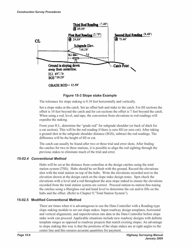
Figure 15-3 Slope stake Example The tolerance for slope staking is 0.10 feet horizontally and vertically.
Set a slope stake at the catch. Set an offset hub and stake to the catch. For fill sections the offset is 10 feet beyond the catch and for cut sections the offset is 7 feet beyond the catch. When using a rod, level, and tape, the conversion from elevations to rod readings will expedite the staking.
From your H.I., determine the “grade rod” for subgrade shoulder (or back of ditch for a cut section). This will be the rod reading if there is zero fill (or zero cut). After taking a ground shot at the subgrade shoulder distance (SGS), subtract the rod readings. The difference will be the height of fill or cut.
The catch can usually be found after two or three trial and error shots. After finding the catches for two to three stations, it is possible to align the rod sighting through the previous stakes to eliminate much of the trial and error.
15-02.4 Conventional Method Hubs will be set at the distance from centerline at the design catches using the total station system (TSS). Hubs should be set flush with the ground. Record the elevations shot with the total station on top of the hubs. Write the elevations recorded next to the elevation shown at the design catch on the slope stake design notes. Spot check the elevations with a level and a rod throughout the area slope staked to ensure the elevations recorded from the total station system are correct. Proceed station-to-station fine-tuning the catches using a fiberglass rod and hand level to determine the cut and/or fills on the hubs and the offset. (Refer to Chapter 9,”Total Station System”).
15-02.5 Modified Conventional Method There are times when it is advantageous to use the Data Controller with a Roading-type slope staking module to set out slope stakes. Input roadway design templates, horizontal and vertical alignments, and superelevation rate data in the Data Controller before slope stake work can proceed. Applicable situations include new roadway designs with definite template ranges as opposed to roadway projects that match existing slopes. An advantage to slope staking this way is that the positions of the slope stakes are at right angles to the center line and this ensures accurate quantities for payment.
Page 15-6 Highway Surveying Manual January 2005
Construction Survey Procedures
Highway Surveying Manual Page 15-7 January 2005
Construction Survey Procedures
Data Controllers running Carlson SurvCE software can slope stake with the user entering pivot offsets, pivot elevations and slope ratios from our computer generated Slope Staking reports at any desired station. A customizable slope staking report in TXT or CSV format can be stored in the controller for later downloading.
In the latter case, it is impractical to input unique templates for every station and therefore manual rod and level techniques are appropriate. (Refer to Chapter 9, “Total Station System”).
15-02.6 Global positioning System (GPS) /Real Time Kinematics (RTK) Method Input roadway design templates, horizontal and vertical alignments, and superelevation rate data or a DTM surface in the Data Controller before slope stake work can proceed. The GPS units read continuously and models the ground surface. The program calculates immediately where the catch point is located. The trial and error method is eliminated using GPS. (Refer to Chapter 8 “Global Positioning System”).
15-02.7 Stake Markings Standard plans have been developed to establish a uniform method of marking survey stakes. This uniformity permits a consistent way of communicating the desired action and checking the Contractor progress in achieving that goal.
Using a different symbology will require documentation to assure that all parties involved understand the meaning conveyed on the survey stakes.
Data Controllers running Carlson SurvCE software can slope stake with the user entering pivot offsets, pivot elevations and slope ratios from our computer generated Slope Staking reports at any desired station. A customizable slope staking report in TXT or CSV format can be stored in the controller for later downloading.
15-02.8 Additional NotesSet a second back-up offset hub and lath for line and distance to centerline only, well beyond the original offset in fill sections. Set the back-up offset hub as far back as possible staying inside of right of way. Many times the offset hubs are destroyed accidentally during the construction of the slopes and all references to centerline are lost through these areas. This additional step will prevent the crew from having to re-survey the area to re-establish centerline for grade control.
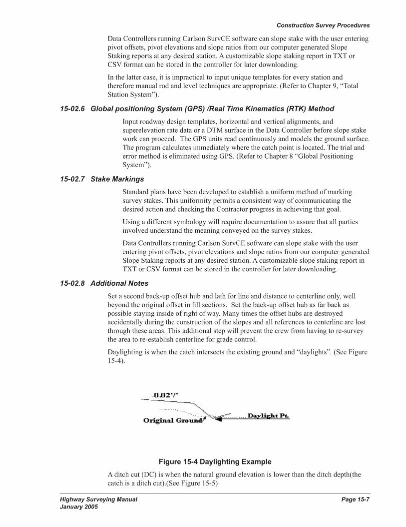
Daylighting is when the catch intersects the existing ground and “daylights”. (See Figure 15-4).
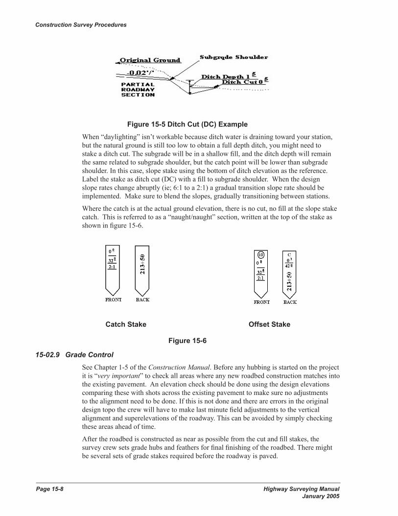
Figure 15-4 Daylighting Example A ditch cut (DC) is when the natural ground elevation is lower than the ditch depth(the catch is a ditch cut).(See Figure 15-5)
Page 15-8 Highway Surveying Manual January 2005
Construction Survey Procedures
Highway Surveying Manual Page 15-9 January 2005
Construction Survey Procedures
Figure 15-5 Ditch Cut (DC) Example When “daylighting” isn’t workable because ditch water is draining toward your station, but the natural ground is still too low to obtain a full depth ditch, you might need to stake a ditch cut. The subgrade will be in a shallow fill, and the ditch depth will remain the same related to subgrade shoulder, but the catch point will be lower than subgrade shoulder. In this case, slope stake using the bottom of ditch elevation as the reference. Label the stake as ditch cut (DC) with a fill to subgrade shoulder. When the design slope rates change abruptly (ie; 6:1 to a 2:1) a gradual transition slope rate should be implemented. Make sure to blend the slopes, gradually transitioning between stations.
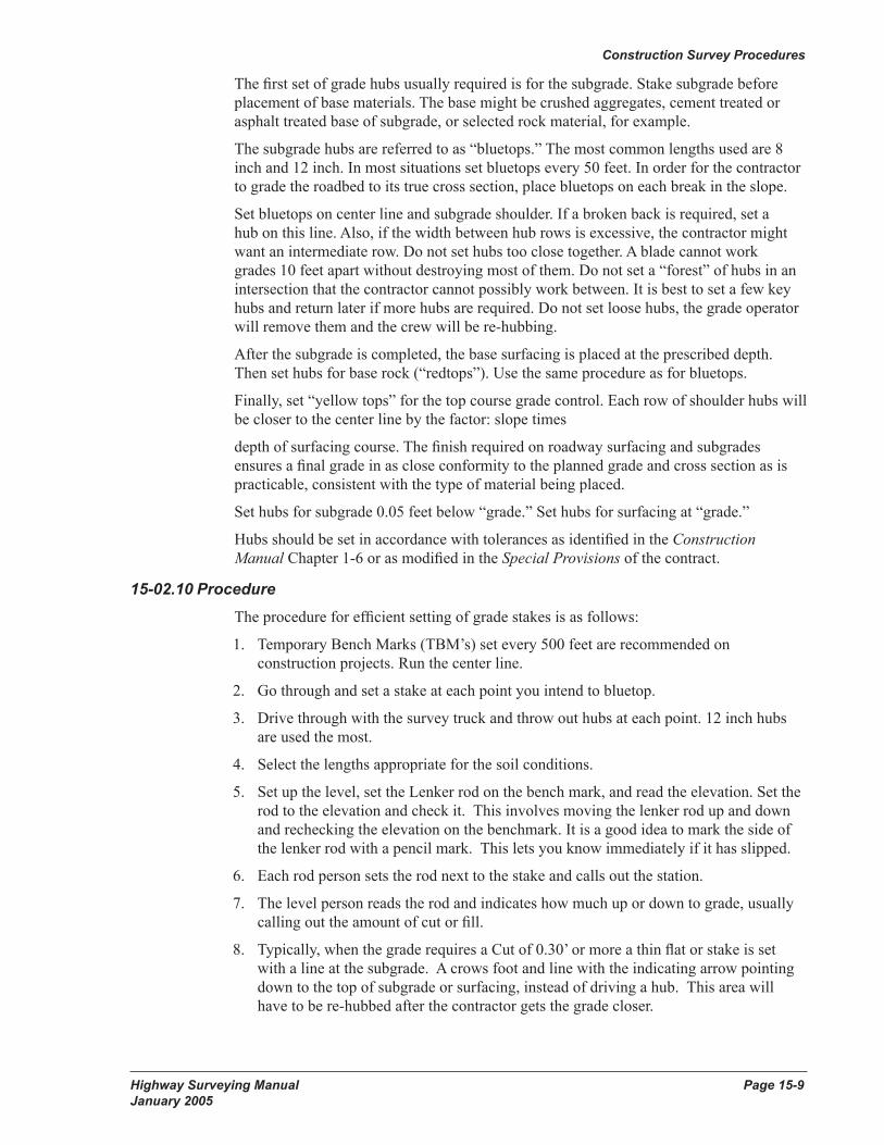
Where the catch is at the actual ground elevation, there is no cut, no fill at the slope stake catch. This is referred to as a “naught/naught” section, written at the top of the stake as shown in figure 15-6.
Catch Stake Offset Stake
Figure 15-6
15-02.9 Grade ControlSee Chapter 1-5 of the Construction Manual. Before any hubbing is started on the project it is “very important” to check all areas where any new roadbed construction matches into the existing pavement. An elevation check should be done using the design elevations comparing these with shots across the existing pavement to make sure no adjustments to the alignment need to be done. If this is not done and there are errors in the original design topo the crew will have to make last minute field adjustments to the vertical alignment and superelevations of the roadway. This can be avoided by simply checking these areas ahead of time.
After the roadbed is constructed as near as possible from the cut and fill stakes, the survey crew sets grade hubs and feathers for final finishing of the roadbed. There might be several sets of grade stakes required before the roadway is paved.
Page 15-8 Highway Surveying Manual January 2005
Construction Survey Procedures
Highway Surveying Manual Page 15-9 January 2005
Construction Survey Procedures
The first set of grade hubs usually required is for the subgrade. Stake subgrade before placement of base materials. The base might be crushed aggregates, cement treated or asphalt treated base of subgrade, or selected rock material, for example.
The subgrade hubs are referred to as “bluetops.” The most common lengths used are 8 inch and 12 inch. In most situations set bluetops every 50 feet. In order for the contractor to grade the roadbed to its true cross section, place bluetops on each break in the slope.
Set bluetops on center line and subgrade shoulder. If a broken back is required, set a hub on this line. Also, if the width between hub rows is excessive, the contractor might want an intermediate row. Do not set hubs too close together. A blade cannot work grades 10 feet apart without destroying most of them. Do not set a “forest” of hubs in an intersection that the contractor cannot possibly work between. It is best to set a few key hubs and return later if more hubs are required. Do not set loose hubs, the grade operator will remove them and the crew will be re-hubbing.
After the subgrade is completed, the base surfacing is placed at the prescribed depth. Then set hubs for base rock (“redtops”). Use the same procedure as for bluetops.
Finally, set “yellow tops” for the top course grade control. Each row of shoulder hubs will be closer to the center line by the factor: slope times
depth of surfacing course. The finish required on roadway surfacing and subgrades ensures a final grade in as close conformity to the planned grade and cross section as is practicable, consistent with the type of material being placed.
Set hubs for subgrade 0.05 feet below “grade.” Set hubs for surfacing at “grade.”
Hubs should be set in accordance with tolerances as identified in the Construction Manual Chapter 1-6 or as modified in the Special Provisions of the contract.
15-02.10 ProcedureThe procedure for efficient setting of grade stakes is as follows:
1. Temporary Bench Marks (TBM’s) set every 500 feet are recommended on construction projects. Run the center line.
2. Go through and set a stake at each point you intend to bluetop.
3. Drive through with the survey truck and throw out hubs at each point. 12 inch hubs are used the most.
4. Select the lengths appropriate for the soil conditions.
5. Set up the level, set the Lenker rod on the bench mark, and read the elevation. Set the rod to the elevation and check it. This involves moving the lenker rod up and down and rechecking the elevation on the benchmark. It is a good idea to mark the side of the lenker rod with a pencil mark. This lets you know immediately if it has slipped.
6. Each rod person sets the rod next to the stake and calls out the station.
7. The level person reads the rod and indicates how much up or down to grade, usually calling out the amount of cut or fill.
8. Typically, when the grade requires a Cut of 0.30’ or more a thin flat or stake is set with a line at the subgrade. A crows foot and line with the indicating arrow pointing down to the top of subgrade or surfacing, instead of driving a hub. This area will have to be re-hubbed after the contractor gets the grade closer.
Page 15-10 Highway Surveying Manual January 2005
Construction Survey Procedures
Highway Surveying Manual Page 15-11 January 2005
Construction Survey Procedures
9. The hammer person drives the hub, stopping above the indicated grade. The rod person checks and then the hammer person drives the hub to grade with light blows. Don’t overdo it. It is easier to tap a hub down a few hundredths than it is to pull one up. A good set of hand signals known to all is useful.
Turn when you reach the limits of your level. Check all rods into a TBM as often as possible. After obtaining a new H.I., check the last hub set, and at the end of the day’s hubbing make sure and check into a known benchmark.
GPS/RTK equipment can be used for setting out and checking grade control for creating a DTM (digital terrain model)or TTM (triangulated terrain model). The equipment will model elevations at any point on the surface DTM/TTM’s.
15-03 DrainageSee Chapter 7 of the Construction Manual.
15-03.1 CulvertsA culvert is an opening (usually a pipe) in the embankment that allows water to pass from one side to the other. Culverts are placed in valleys that would otherwise be dammed by the highway embankment.
Culverts may be concrete or metal pipe, pipe arches, or concrete box culverts. The amount of water passing through and the height of the fill determine the size and type of culvert to be installed.
If the culvert is to be constructed for a flowing stream, a channel change is usually required. The culvert is constructed on the new channel alignment and the stream is then diverted through it.
If the channel is dry at the time of construction, the contractor might be required to partially build the embankment before placing pipe.
To lay out culvert installations, perform the following steps:
1. Consult the contract plans for station and offset for ends of the installation.
You might be required to field fit culverts. If so, find the slope catch in the channel bottom for each end of the culvert.
Check the templates to be sure widening for guardrail has been included if necessary.
2. Set a hub and tack at the indicated positions for each end of the culvert. Typically we set an offset reference point 10 feet past the end of the pipe with a grade to the pipe.
3. Measure distance between hubs.
4. Set a parallel offset line at a distance convenient for the contractor. Usually 10 feet is adequate.
5. Beginning at the downstream end, set and station hubs along the offset line at 25 feet intervals. Place the beginning hub at station 0+01 or greater.
6. At the downstream end, set a second hub to ensure proper positioning of the first section of pipe.
7. Obtain elevations on all offset hubs and corresponding ground elevations at the center line of the pipe. Record on “Field Note Record for Drainage,” WSDOT Form 422-637.
8. When the trench will be excavated to a depth of 4 feet or more, obtain elevations at the horizontal limits of the trench.
Page 15-10 Highway Surveying Manual January 2005
Construction Survey Procedures
Highway Surveying Manual Page 15-11 January 2005
Construction Survey Procedures
9. Compute the flow line grade of the culvert for each offset hub. Subtract from hub elevation. Record on the form.
10. Mark and place stakes at the hubs, recording the station, offset, code number, and cut.
11. Check all computations and check all stakes for accuracy in recording.
12. Complete the sketch on Form 422-637 along with other required data and submit to your supervisor.
15-03.2 SewersSewers are a closed system of watertight pipes that generally begin and end in some sort of drainage structure.
Storm sewers, manholes, or catch basins are located to allow water in or out of the system and provide access for cleanout. Manholes are usually spaced at a maximum of 300 feet. Catch basins are spaced often enough to drain the roadway.
Sanitary sewers have manholes for maintenance but no other openings. In sewer design, the crowns of all pipes coincide at the center of the manhole. Therefore, water running through a small pipe into a larger pipe at a manhole will fall by the difference in pipe size.
On the drainage plan sheets of the contract plans you will find a circled number and a line drawn to each drainage structure. The plan sheet number with the circled number are the “structure note” or “code.”
The drainage profile sheets show the station, offset, flow line grade, and top of grate elevations for each installation. The top of grate elevation is for the center and is usually at the pavement elevation for manholes, and 1 inch below the pavement elevation for catch basins and grate inlets. The grates are to be set on the same slope as the pavement. Communication between the crew and the contractor is “very important” when setting elevations for top of grate inlets. Make sure the contractor and inspector know that the elevations are already set 1 inch below the pavement elevation.
Grades are critical, especially for sanitary sewers. Therefore, pay close attention to elevations.
The “structure notes” section of the contract plans tabulates the lengths, size, type of pipe, appurtenances, and any special note for each installation.
In laying out sewers, the following steps are taken:
1. Study the plans, special provisions, structure note sheets, Standard Specifications, and appropriate standard drawings before starting. This is most important. In studying the system you are staking, be sure to consider the whole system, not just the area you are working in. You might pick up an error on the plans before it gets constructed.
Make sure that the back edges of catch basins will be in the curb line and that manhole lids are not in the curb line.
2. Establish the locations at the center of manholes, catch basins, or any other connections by setting a guinea.
A hub and tack serves no purpose since it will get dug out. Set an offset hub at the same offset distance as for the pipe. Then set a second offset hub in line with the first. This will allow the contractor and inspector to be sure of accurate placement of the structure.
Page 15-12 Highway Surveying Manual January 2005
Construction Survey Procedures
Highway Surveying Manual Page 15-13 January 2005
Construction Survey Procedures
3. Compare the plan layout against the ground layout. Always pay attention to the drainage layout in the field. Does it look correct compared to the plan layout? If you suspect an error in the plans or if something looks out of place, advise your supervisor or project inspector. Do not make changes without approval. For catch basins or irregular shaped structures “VERIFY” design offset is to center of structure or center of grate.
4. Set RP hubs for an offset line parallel to the pipe at 25 foot intervals. It’s handy for the drainage inspectors if an offset RP hub is set at the end of second length of pipe (20’ pipe length, so put a hub at 40’). Station the hubs using 0+00 at the center of the manhole or catch basin at the lower end of the pipe.
Offset the RP’s enough to allow pipe laying and digging equipment room to work along the trench but not so far away that they are difficult to transfer to the trench. Usually 10 to 20 feet is a good offset distance, depending on the depth and size of pipe. Consult with the pipe-laying contractor and agree on the offset distance.
5. Obtain elevations on the offset hubs and ground at the center line of the pipe. Record the elevations on WSDOT Form 422-637, Field Note Record - Drainage.
6. Compute the flow line grade of the sewer at each Reference Point (RP) hub. Subtract from hub elevation and record on the form.
7. Mark and place stakes at the hubs and record the drainage code number, station, offset, and cut.
8. Check all computations and check all stakes for accuracy in recording.
9. Complete the “Field Note Record for Drainage.” One sheet is required for each drainage structure note or code. On the form, show a simple plan view and profile along with a north arrow and center line ties. On the back of the sheet, show the pipe stations at 25 feet intervals, flow line grades, ground elevations at the center line of the pipe, the elevations of the offset hubs, and the cuts from the offset hub to pipe flow line grade. The inspector completes the quantity calculations.
When completed, submit the form to your supervisor.
As in all survey work, it is easy to transpose numbers or make other blunders. Therefore, have some other qualified person check all computations and spot check instrument readings before leaving the site.
15-04 Structure LayoutThis addresses the procedures to be followed for surveying and staking structures.
Review Section 1-5 and chapter 6 of the Construction Manual before proceeding. Review the plans, specifications, and special provisions.
15-04.1 Horizontal ControlFor structure layout, establish a horizontal control network using second order procedures. (See Chapter 7 “Accuracy Classification and Standards”.) Place control points in strategic locations so that any point within the bridge site can be set from at least two control points. Provide control points that are substantial enough to remain in place and undisturbed for the duration of the bridge construction. A rebar and cap set in concrete can be used for these control points. “Always” use the same set of control points to build the bridge from one side to the other.
Page 15-12 Highway Surveying Manual January 2005
Construction Survey Procedures
Highway Surveying Manual Page 15-13 January 2005
Construction Survey Procedures
The next step is to establish the structure center line. Sometimes this center line differs from the line used to construct the roadway. Study the plans carefully to determine the correct line. This is not always plainly marked and it is easy to overlook some variation in the alignment. Resolve any problems before setting stakes.
Run the center line (make sure it closes within the site location) and all other controls that are pertinent to the structure.
Check distances across streams, highways, or other obstructions by use of an approved electronic distance measuring device (EDM).
Never rely on any existing station to establish pier or bridge footing locations without checking it first. Always double check all distances to all existing or proposed structure features to ensure constructibility. Errors in locating the footing might necessitate extensive revision in the design of the structure or removal of the incorrectly located foundation.
15-04.2 StakingStake pier locations in accordance with the footing layout included in the plans. After the piers have been staked, stand back and “eyeball” the entire layout, if possible, to determine if it looks correct. Check the depth of footing compared to the ground line, cut or fill slopes, or stream bed. Take profiles along the center line of each pier or bent and at all corners for use in excavation calculations.
15-04.3 Vertical ControlSet the vertical control after the horizontal control. Set temporary bench marks (TBM) in readily accessible locations where they will also be safe during construction. Extra TBMs are advisable to ensure survival.
The vertical control requirement for major structures is second order and for minor structures is third order. (See Chapter 7 “Accuracy Classification and Standards”.)
When setting TBMs for structures, remember that structures are very susceptible to settlement. Not only do the piers settle but the ground in the area of the piers can also settle. Therefore, it is essential to set a control TBM outside the area of influence so that it can be used to monitor TBMs near the structure. Settlement can occur on the day of the pour or more than a year later, so it is something that requires close attention. Settlement is common in some concrete structures. Notify the inspector and project engineer when it is detected.
Locate TBMs at each end of the structure. If the structure is very long, it might be necessary to set TBMs in intermediate locations along the structure. Consider locating TBMs in the vicinity of each pier.
15-04.4 Layout and ReferencesStake the piers/footings at the locations shown in the plans. These may be staked directly by station and offset from the center line or from the control points established previously. Stake reference points (RP) in line with the center of the pier or footing to ensure recovery of the pier after excavation.
Consider the following concepts when setting RP’s.

Page 15-14 Highway Surveying Manual January 2005
Construction Survey Procedures
Highway Surveying Manual Page 15-15 January 2005
Construction Survey Procedures
Consider the length of time that the point must remain in a precise, fixed position and be resistant to outside forces such as traffic and frost heave. Hubs are susceptible to heave if not planted deeply enough and will weather rapidly if shattered. If not driven straight, small diameter rebar has a tendency to straighten during weather cycles. If a rock is driven along the side of a rebar to get it on line, it will only remain in that position until the next heavy rain or frost.
A 5:1 ratio from RP to deck elevation is sufficient width on structures other than lids.
Place the reference points so they are clear of other construction features and so they will not be affected by ground movements caused by large excavations or embankments. Set adequate references so that if some are lost the pier can still be easily reestablished. References are a very critical item in the layout of the structure. A little extra time spent placing good references can save time throughout the life of the project.
15-04.5 Checking LayoutHave the layout of the structure and the references independently checked by a different survey crew using a different control point. Whenever possible, avoid having the same crew perform the independent check. Also have all survey notes checked by another person.
Whenever possible, determine distances by direct measurement.
The contractor will excavate for the footings. (The party chief as well as all crew members may only enter properly shored excavations. It is a safety violation to do otherwise.) Bluetop the bottom of the excavation for grade, and set the form corner hubs.
After the piers or footings have been cast, the reference hubs can be used to center and plumb the column forms and then the pier cap forms.
15-04.6 SuperstructureAs the contractor’s work progresses to the superstructure, the survey work also continues.
For box girder bridges, the bottom deck, diaphragms, webs, and exterior walls are aligned on the plywood decking. For precast girder bridges, points are set for precise placement of the girders.
When working on structures, safety procedures for work above ground or water must be known and observed. Due to the heights involved as well as heavy materials being lifted overhead and proximity of water or traffic, the potential for injury is high. It is the responsibility of the party chief to ensure that items such as handrails are in place before the crew begins work.
The contractor will construct the forms for the roadway deck. The roadway will extend outward of the exterior walls or girders. This portion of the bridge is called a soffitt or overhang. The decking forms are supported by either steel brackets or bracing against the falsework below. On the overhang decking, the line marking the edge of the roadway deck must be laid out. The elevation at each bracket/brace is observed and the soffitt is adjusted until the decking is set at its predetermined elevation. This procedure is known as grading the overhang. The brackets/ bracing are usually spaced at 4 feet along the entire length of the bridge.
Only approved equipment in proper adjustment, calibration, collimnation and approved rods may be used for determining elevations and grades for structures. Remember to check the TBMs from the control benches after major concrete pours and after placement of large quantities of rebar.
Page 15-14 Highway Surveying Manual January 2005
Construction Survey Procedures
Highway Surveying Manual Page 15-15 January 2005
Construction Survey Procedures
The interior decking forms are usually adjusted to grade after placement of the rebar so that some of the “crush” is taken up. The girders or web walls will have rebars protruding vertically from the concrete. Grade marks can be filed into the bars for each bay and adjustments are made by string lining. The screed rails are set up and the crew will grade them at each support bracket.
“Critical” areas to watch for in deck construction are errors built into structures due to expansion caused by temperature changes. In steel structures, camber built into truss spans can increase more than 1 inch on a hot day. When doing this type of work, a point can be set at mid span and then monitored throughout the day to determine what if any adjustment to apply to the layout grades. This is less obvious on concrete spans so it is easier to miss. This is probably the greatest cause of dispute when state crews are required to check grades after they are set and adjusted by the contractor. A typical scenario has the grades set in the morning when it is cool and checked in the afternoon by a different survey crew.
Perform the final survey operation after the falsework has been released. This is the grading of the top of the traffic barrier. First, the face of barrier line is established and deck elevations observed at each joint in the forms. The deck profile is plotted and top of barrier grades are determined. “Low spots” can be filled but any “high spots” in the deck will essentially be a controlling factor. The chamfered grade strip is nailed to the back form and concrete is poured to match the grade.
15-04.7 Documentation“Field Note Records” will be required for payment of the contractor. Keep a field book record of observations, sketches, horizontal and vertical control monuments, and Height of Instrument (HI’s) for each grading operation. Also keep computer calculations and other papers. A separate field book for each structure is recommended. Turn these records over to the office engineer for safekeeping upon completion of the project.
15-05 Miscellaneous Construction Surveying
15-05.1 Pit Site/Quarry Site, Stockpiles, Sundry Site, and ReclamationPit Areas
One of the many tasks required of survey crews is to gather field data of pit site areas for the purpose of generating quantities for the state to pay contractors.
With current surveying practices, Digital Terrain Model (DTM) data (Topographic) is gathered of the pit site area before any work is done (original ground) and then new DTM data is gathered after work has been performed (remeasure).A conventional total station system (TSS) or the GPS/RTK equipment can be used.
The contractor may request a remeasure of the pit site at a time when the work is getting close to plan quantities.
The procedure is as follows:
1. Gather crew together and discuss strategy for collecting data.
2. Set a minimum of two control points to establish a set up station and a back sight. Assumed coordinates and elevations may be used for this type of work since the object is a volume. Check with the Regions’ Pit’s and Quarries division, there may already be control in the area. It is always better to work from known control points (such as Washington Coordinate System) when available, than assumed coordinates.
Page 15-16 Highway Surveying Manual January 2005
Construction Survey Procedures
Highway Surveying Manual Page 15-17 January 2005
Construction Survey Procedures
3. Set additional control points, as necessary, to be able to Topo the entire pit site area. Locate all control points where they will not be disturbed by the work.
4. Set up a new Topo job in the data collector with a note that includes the pit site number, date, job name, and the names of crew members.
5. Gather data for DTM. It is very helpful to mark each point where a shot is taken with a paint spot so you can visually see areas where shots are needed.
6. Download, edit, backup, and create DTM. For remeasures, create a new job in the data collector and follow the aforementioned procedures taking care to pick up any terrain changes from the original ground (first DTM).
Manual cross section methods may be used instead of DTM methods. The procedures are as follows:
1. Establish a base line and reference it in a safe location so that it can be replaced after the material has been removed. Fifty foot intervals are usual but closer spacing might be necessary if the ground is very irregular.
2. Cross section the ground prior to removal of any material.
3. Establish temporary bench marks (TBM) for vertical control. Set 2 or 3 TBMs around the pit for backup.
4. On completion of the removal, or at any time an estimate is required, reestablish the base line and cross section the area. This will be the remeasure line on your notes.
Stockpiling
The volume for pay quantity will be determined by computing the volume between the original ground surface and the stockpile surface using Digital Terrain Model (DTM) techniques or cross sectioning.
First study the contract plans to determine the following:
• Number of stockpiles required for various aggregates.
• Which aggregates are to be surveyed for pay quantity.
• Quantity of aggregates required in each stockpile.
An on-site review of the stockpile area with the project inspector and contractor will determine where the best stockpile locations are in relationship to the various plant operations.
1. Locate stockpile areas to ensure easy access by trucks and loading equipment.
2. Do not establish stockpiles under power lines.
3. Maintain sufficient distance between the various stockpiles to prevent mixing the various classes of materials.
The procedure for staking stockpile areas is as follows:
4. Find out how much area is available for the stockpiles. Often a scale drawing of the area will be needed.
5. From the proposed planned quantities, determine suitable dimensions for piles that will best fit into the available areas. (If stockpiles are for maintenance, check with the maintenance foreman for the best locations for their use.)
6. Lay out control points, base lines, and all corners of each pile and indicate materials to be piled at each located area.
Page 15-16 Highway Surveying Manual January 2005
Construction Survey Procedures
Highway Surveying Manual Page 15-17 January 2005
Construction Survey Procedures
7. Follow the procedures given for DTM technique for pit areas or, follow steps 8 through 12 below for cross sectioning.
8. Place stations along the base line at 20 foot intervals and at any points where irregular breaks in the ground require extra stations for accurate measurements.
9. Cross section the ground from the stations established along each base line. Take rod shots at 25 foot intervals and where ground line irregularities require extra rod shots for accurate measurement.
10. Set base line references in protected areas.
11. Set a TBM in a safe place. Assumed elevations can be established if an actual bench mark is not handy. Use the same bench mark for all stockpiles being constructed in the immediate area.
12. After the stockpile is complete, remeasure the pile and compute the quantity.
Sundry Site and Reclamation Plans
Refer to the Plans Preparation Manual and the Standard Plans for Road, Bridge, and Municipal Construction for survey requirements.
15-05.2 Erosion controlErosion control is to preserve the erodible surfaces of our highway projects. Steep slopes are the most susceptible to erosion. Covering with topsoil then planting grass, sodding, bark mulch, plants, and trees are used for erosion control.
Measurement and payment are by area, by volume, or by actual count of such things as plants and trees. For items paid by area such as seeding, mulching, and fertilizing, measure the area to be covered.
For example: in a quadrant of an interchange, start by laying out a base line. The base line may be parallel or skewed to the highway, ramp, or crossroad. If the base line is on a skew, tie the ends to one of the control center lines.
After the base line is laid out and stationed, measure to the edges of the planting area perpendicular to the base line at 50 foot intervals or at the breaks. These measurements are made directly on the ground instead of level chaining.
Prepare a “Field Note Record”, WSDOT Form 422-636EF showing the base line and center line ties and measurements to the edge of the planting area. The inspector then computes the areas for payment. An alternative is to gather a Topo of the site with a closed chain defining the perimeter of the area. Then the design software will build a DTM and build a report using the Surface Volume/Area command to provide the surface area.
15-05.3 Guide PostThe locations for guide posts are shown in the contract plans. Check the Standard Plans and Standard Specifications for the distance from the edge of the pavement as it might vary in different areas. Check with the project engineer because maintenance might have some special requests as to the location of the guide posts.
In staking guide posts, usually all that is required is a stake at the location of each guide post. Sometimes a paint mark on the edge of the pavement will be sufficient. Consult with the contractor who will be doing the work.
More information can be found in the Design Manual Chapter 830 or the Manual on Uniform Traffic Control Devices for Streets and Highway (MUTCD).
Page 15-18 Highway Surveying Manual January 2005
Construction Survey Procedures
Highway Surveying Manual Page 15-19 January 2005
Construction Survey Procedures
15-05.4 GuardrailStudy the plans, specifications, and Standard Plans specific to the project before beginning. This is especially important with guardrail as the design details change frequently.
Use the face of rail and top of rail as the horizontal and vertical references for guardrail.
Consult the contractor for the type of reference line needed. The contractor might want the face of rail staked, the center of post, back of the post, and so on, and usually will want the center of the bolt or the top of the post referenced for grade.
Resist the tendency to overstake guardrail. Normally, only the guardrail ends (flares and parabolas) and the tapers are staked. The following applies in most cases.
• Don’t stake every post. Just stake the beginning and ending post of the straight run.
• In most situations, a reference hub every 50 feet is adequate.
• On sharp horizontal or vertical curves, you might need a hub every 30 feet.
• On tight radius curves, you might need hubs at 10 feet.
• A hub and tack is usually used to mark line and grade.
• Only stake every post in special areas where the situation requires exact placement.
• If the contractor wants the center or back of the post staked, locate the hubs between posts.
• If the contractor wants the face of the rail staked, it is not necessary to keep the hubs between the posts.
Do not level chain as the rail has a finite length that follows the slope of the road.
15-05.5 FencingThe locations for fencing are given in the contract plans or the special provisions.
Consult the project inspector and the contractor for the type of reference line.
The following will apply in most cases:
• Stake the pull points, gate post, corner post, and end posts.
• For all types of fence, a change in alignment of 2 feet tangent offset, or more, for the next post is considered a corner.
• Stake all fence 1 foot inside Right of Way, unless directed otherwise.
More information can be found in Design Manual Chapter 1460.
15-05.6 Illumination and Traffic SignalsFirst study the plans, specifications, and standard drawings. The locations are given in the contract plans. A visual check of the site is needed to ensure that the location is suitable.
See the plans for the location and the height of the luminaire. A cross section is necessary at that section of roadway to determine the base elevation. “Double check” the cross section elevations, subgrade shoulder and existing ground elevations to the top of the luminaire base to make sure the placement is correct. There is a limit to the amount of adjustment the contractor can make if it is set too low and if it is set too high it may have to be re-set.
Page 15-18 Highway Surveying Manual January 2005
Construction Survey Procedures
Highway Surveying Manual Page 15-19 January 2005
Construction Survey Procedures
Stake the center of the base for line and grade. The stake for the center will be destroyed during excavation and must, therefore, be referenced. Locate the reference points outside the excavation area, but near enough to be useful to the contractor. Show the offset distance, cut or fill to the top of the luminaire base, and stationing on the stakes.
Stake the conduit runs according to the plan or as directed by the project inspector. A paint line will generally be adequate for the conduit, but consult the project inspector and the contractor for their needs.
Stake and reference the junction boxes. See the plans for the location.
Locate service cabinets and reference them to line and grade.
When staking illumination, good communication with the project inspectors is needed. The survey crew must be aware of their needs and aware of any changes that are necessary.
Good communication between the crew and inspector will aid the crew in determining what is needed.
More information can be found in Design Manual Chapters 840 and 850.
15-05.7 SigningSteel Sign Supports
Study the plans, specifications, and standard drawings. The following procedure usually can be followed:
1. Locate the site of the sign. It will be given on the plans but you will have to check it for visibility.
2. Take a cross section at the sign location. Include the edge of the traveled way in the section.
3. Set hubs at the footing locations with references to the top of the footings.
With this information the exact post length can be computed, and the sign can be installed later. Unless your reference hubs are lost, no other staking is usually required.
On sign bridges and large cantilevered signs that have electric power to them, you will have to also locate and stake the conduits. Follow the plans and try to locate the conduits outside the pavement area if possible.
Miscellaneous SigningThe locations for these facilities are given in the contract.
All that is required for wood sign posts is the location by station and the offset. The required heights and other details are given on the plans and are the responsibility of the contractor.
More information can be found in Design Manual Chapter 830 or the Manual on Uniform Traffic Control Devices for Streets and Highway (MUTCD).
15-05.8 Pavement MarkingReview the contract plans and special provisions, Standard Specifications, and Standard Plans prior to laying out pavement marking.
Prior to layout, meet with the contractor to determine the intervals required for layout marks. Once layout is complete, the contractor completes preliminary spotting prior to pavement marking.
Page 15-20 Highway Surveying Manual January 2005
Construction Survey Procedures
Highway Surveying Manual Page 15-21 January 2005
Construction Survey Procedures
Center line is generally used as the control points for pavement marking although use of an offset is acceptable. Lay out all the pavement marking from the same control to maintain correct spacing and lane widths. Paint marks are typically used when establishing control and for layout.
Center Line
Mark center lines with paint.
Curves
Use a total station and set the curve points or use a 300 ft or longer cord, eyeball in a curve, and paint over it. By doing the tangents first, it will make the transitions to curve look better when you eyeball in a curve.
When laying out the initial paint marking use very small preliminary dabs until you verify the plans are correct. At times there can be errors in the plans and recalculation may be needed on lane tapers, stationing etc. Visually check dabs looking back and ahead on line making sure it looks correct. If the crew finds an error and corrects it, use black paint to cover the preliminary dabs. Always inform the project inspector or the project engineer when finding an error.
15-05.9 Concrete CurbWhen staking concrete curb, check the plans carefully to determine the correct location and grade.
Since the face of the curb is battered and the back of the curb is plumb, the best control point for line and grade is the top and back of curb.
Set hubs and tacks at 30-foot intervals on a 3 foot offset line to the back of curb. On radius curves of 50 feet or less, space hubs and tacks at 10 feet or less as needed.
Run levels on the hubs and determine the difference in grade from the hubs to the top of the curb. Prepare stakes showing the difference as a cut or fill and the offset. Flagging on the stakes is not necessary.
“Always” check any new curbs elevations that are being tied into existing/new pavement (such as a grind and inlay with different surfacing depths up to finished, etc.). Just because the plan profiles show elevations at top of curb does not mean that they are error free. Check by calculating the measure up at centerline from the subgrade or existing surfacing, across what will be the finished roadway at the proper super to the new curb elevation making sure it is correct.
Prepare a “Field Note Record”, WSDOT Form 422-636EF, showing the plan view of the curb line along with the length staked.
15-06 WSDOT Standard Color CodesSome standards apply to all construction phases. Follow the standard color codes for survey ribbon and spray paint to ensure uniformity and minimize confusion.
Color Code for Spray Paint
It is desirable to conform to the WUCC/APWA/ULCC standard color codes for utilities. “White” is acceptable for stationing along the paved shoulder. “Pink” is the accepted color for all other survey markings per the national standard utility color code list.
Page 15-20 Highway Surveying Manual January 2005
Construction Survey Procedures
Highway Surveying Manual Page 15-21 January 2005
Construction Survey Procedures
Flagging Color Code for Construction Stakes
It is desirable to have a uniform color code system throughout the state so the contractor’s personnel will be able to readily recognize the work item referenced.
Whenever flagging is necessary on the project, use the following flagging colors:
Activity Flagging Color
Clearing and Grubbing White
Right of Way Red
Slope Stakes Blue
Center line Yellow
Drainage Blue
Signing and Illumination White
References and Control Multicolor
Selective Thinning Orange (for tree removal)
Trees Remaining Blue
15-7 Post Construction SurveySee Chapter 16 “Monumentation and Survey Records” for guidelines on location, placement and types of monuments and documentation needed for your project. It is vital that a post construction survey be performed on projects to ensure that associated documentation and monumentation are accurate and up to date.
15-8 Equipment Table
15-08.1 EquipmentThe ideal rod to use is the Lenker or self-reducing type. Grade rods do not have to be computed as with the Philadelphia rod. The Lenker enables you to read the elevation directly on the rod with no computations required. For example, the TBM elevation is 127.68. The rod is set on the TBM and the rod person adjusts the tape until the level person reads 7.68 and then locks the tape in place. If the elevation of the bluetop is to be 125.15, then the hub is driven until the level person reads 5.15 on the rod and no computations are required.
If you use a Philadelphia rod however, the following computations are required: The TBM elevation is 127.68. The level person reads 5.06. The HI is then 132.74. The grade elevation (125.15) is subtracted from the HI (132.74) to yield a grade rod of 7.59. Thus, when the hub is driven so the level person reads 7.59, the hub is at grade. Grade rods have to be computed for each hub set.
A 12 lb hammer is a good all around size for driving the hubs. A lighter hammer requires too many blows to drive a hub into a well compacted grade, which is tiring and increases chances the hub will be shattered. The heavier the hammer the better. Skill with a hammer is the controlling factor in the speed at which the crew can work. A pick and shovel are necessary tools when the grade is a little high. Digging below grade before driving the hub makes the hub easier to drive. Placing centerline Cuts and Fills is a very good interim step between slope stakes and bluetopping. If the grade is consistently high or low, halt operations and inform the inspector. If the grade is suspected of not being close, spot check it before setting up operation. Painting, on the ground, the amount high or low might save time in the long run.
Page 15-22 Highway Surveying Manual January 2005
Construction Survey Procedures
A small pruning saw can save much time and work in some situations. In a very hard grade, often the hub will go so far and then bind up. The hub will shatter before getting to grade. If the hub is solid, saw it off at grade. The alternatives are: keep pounding and if the hub shatters set another; remove the hub and drive a frost pin to provide a hole for the hub; or insert another hub into the shattered hub, driving it down to the elevation needed (this method prevents loose hubs). Periodically have the hammered end of the frost pin cut off. Do not use a mushroomed tool.
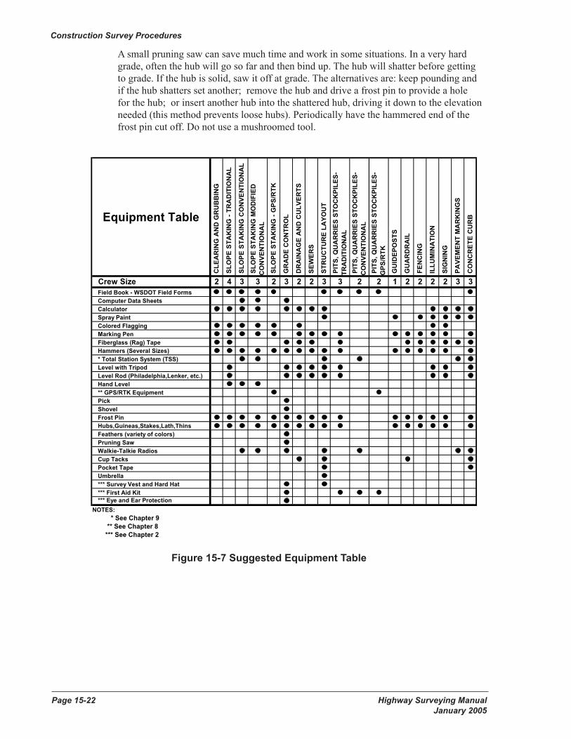
Figure 15-7 Suggested Equipment Table
Equipment Table C
LEA
RIN
G A
ND
GR
UB
BIN
G
SLO
PE S
TAK
ING
- TR
AD
ITIO
NA
L
SL O
PE S
TAK
ING
CO
NVE
NTI
ON
AL
SLO
PE S
TAK
ING
MO
DIF
IED
CO
NVE
NTI
ON
AL
SL O
PE S
TAK
ING
- G
PS/R
TK
GR
AD
E C
ON
TRO
L
DR
AIN
AG
E A
ND
CU
LVER
TS
SEW
ERS
STR
UC
TUR
E LA
YOU
T
PIT
S, Q
UA
RR
IES
STO
CK
PILE
S-TR
AD
ITIO
NA
L P
ITS,
QU
AR
RIE
S ST
OC
KPI
LES-
CO
NVE
NTI
ON
AL
PIT
S, Q
UA
RR
IES
STO
CK
PILE
S-G
PS/R
TK
GU
IDEP
OST
S
GU
AR
DR
AIL
FEN
CIN
G
ILLU
MIN
ATI
ON
SIG
NIN
G
PA
VEM
ENT
MA
RK
ING
S
CO
NC
RET
E C
UR
B
Crew Size 2 4 3 3 2 3 2 2 3 3 2 2 1 2 2 2 2 3 3Field Book - WSDOT Field FormsComputer Data SheetsCalculatorSpray PaintColored FlaggingMarking PenFiberglass (Rag) TapeHammers (Several Sizes)* Total Station System (TSS)Level with TripodLevel Rod (Philadelphia,Lenker, etc.)Hand Level** GPS/RTK EquipmentPickShovelFrost PinHubs,Guineas,Stakes,Lath,ThinsFeathers (variety of colors)Pruning SawWalkie-Talkie RadiosCup TacksPocket TapeUmbrella*** Survey Vest and Hard Hat*** First Aid Kit*** Eye and Ear Protection
NOTES: * See Chapter 9
** See Chapter 8 *** See Chapter 2
Figure 15-7 Suggested Equipment Table
Chapter 15 Construction Survey Procedures Highway Surveying ManualPage 15.24 Draft 10/18/2004