Embed Size (px)
Citation preview
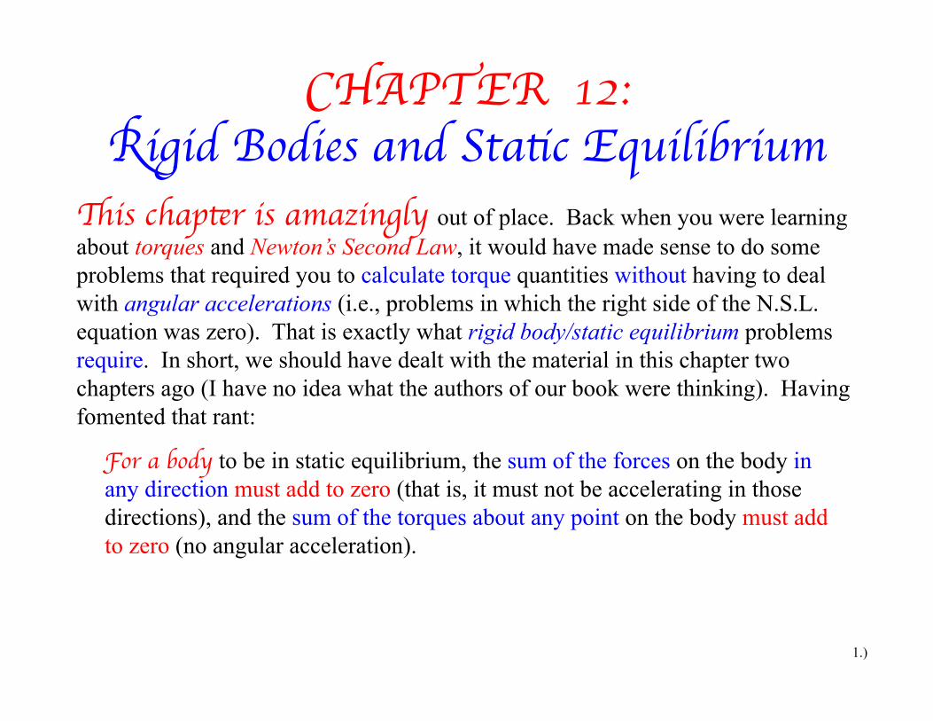
CHAPTER 12:Rigid Bodies and Static Equilibrium
1.)
This chapter is amazingly out of place. Back when you were learning about torques and Newton’s Second Law, it would have made sense to do some problems that required you to calculate torque quantities without having to deal with angular accelerations (i.e., problems in which the right side of the N.S.L. equation was zero). That is exactly what rigid body/static equilibrium problems require. In short, we should have dealt with the material in this chapter two chapters ago (I have no idea what the authors of our book were thinking). Having fomented that rant:
For a body to be in static equilibrium, the sum of the forces on the body in any direction must add to zero (that is, it must not be accelerating in those directions), and the sum of the torques about any point on the body must add to zero (no angular acceleration).

!τ = !r F⊥
F
F!
θ
F⊥ = Fsinθ
!r
Formally defined, the MAGNITUDE of the torque generated by the force on the wrench is mathematically equal to:
2.)
As can be seen in the graphic, the perpendicular component of the force is equal to:
where is defined as the angle between the line of the force and the line of the position vector . (This definition is going to be important later.)
!rθ
This means the torque can also be written as:
!τ = !r F⊥
= !r!F sinθ
F⊥ = Fsinθ
!τ
A Recap of Torque Calculations
!F = 5 N
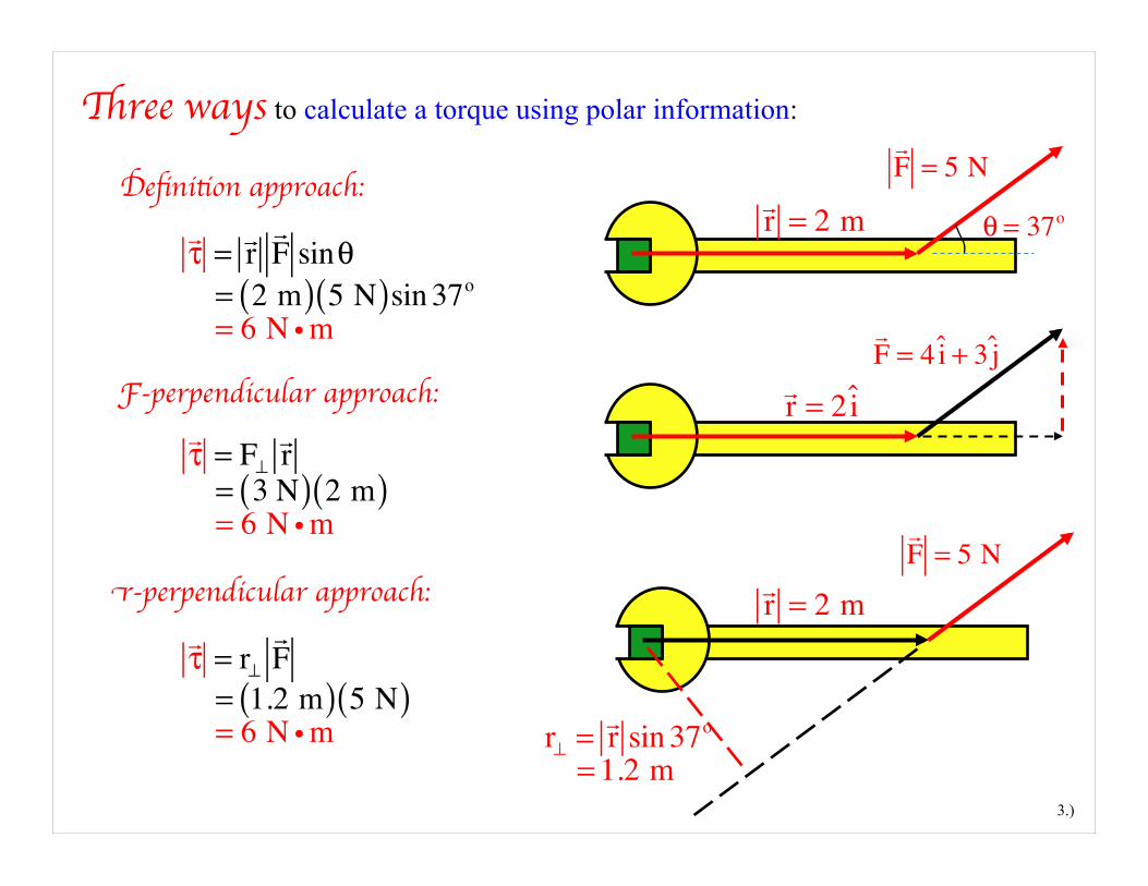
Three ways to calculate a torque using polar information:
θ = 37o
3.)
Definition approach:
!τ = !r
!F sinθ
= 2 m( ) 5 N( )sin 37o
= 6 N i m
!r = 2 m
!F = 4 i + 3 j
F-perpendicular approach:
!τ = F⊥
!r = 3 N( ) 2 m( ) = 6 N i m
r-perpendicular approach:
!τ = r⊥
!F
= 1.2 m( ) 5 N( ) = 6 N i m
!r = 2i
r⊥ = !r sin 37o
= 1.2 m
!F = 5 N
!r = 2 m
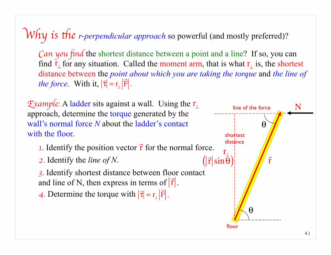
Why is the r-perpendicular approach so powerful (and mostly preferred)?
4.)
Can you find the shortest distance between a point and a line? If so, you can find for any situation. Called the moment arm, that is what is, the shortest distance between the point about which you are taking the torque and the line of the force. With it,
r⊥
!τ = r⊥
!F .
r⊥
Example: A ladder sits against a wall. Using the approach, determine the torque generated by the wall’s normal force N about the ladder’s contact with the floor.
r⊥ line of the force
θ
θ
1. Identify the position vector for the normal force. !r
!r2. Identify the line of N.
N
3. Identify shortest distance between floor contact and line of N, then express in terms of .
!r
r⊥ !r sinθ( )
4. Determine the torque with !τ = r⊥
!F .
floor
shortest distance
Example 1: A standard rigid body problem: Derive expressions for all the forces acting at the floor and wall of an upright, stationary ladder of length L and mass against a frictionless wall (that is, a wall that provides no vertical force component) if a man of mass stands a distance 3L/4 from the floor.
5.)
θ
f.b.d.
Fx :∑ N − H = mLax
⇒ N = H
N
mLg
HV Yes, H is friction and V is a normal, but
conventionally, this is the way they are denoted.
Fy :∑ V− mLg − mmg = mLax
⇒ V = mLg + mmg
Need one more equation. Where to get it? By summing torques about ANY point and putting the sum equal to zero!
0
0
mmg
mLmm
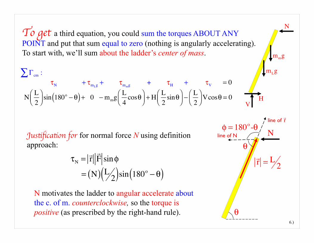
To get a third equation, you could sum the torques ABOUT ANY POINT and put that sum equal to zero (nothing is angularly accelerating). To start with, we’ll sum about the ladder’s center of mass.
6.)
N
mLg
HV
mmg
Γcm :∑ τN + τmLg + τmmg + τH + τV = 0
N L2
⎛⎝⎜
⎞⎠⎟ sin 180o − θ( ) + 0 − mmg L
4cosθ⎛
⎝⎜⎞⎠⎟ + H L
2sinθ⎛
⎝⎜⎞⎠⎟ −
L2
⎛⎝⎜
⎞⎠⎟ Vcosθ = 0
Justification for for normal force N using definition approach:
τN = !r!F sinφ
= N( ) L2( )sin 180o − θ( )
N
!r = L 2
φ = 180o-θ
θ
θ
N motivates the ladder to angular accelerate about the c. of m. counterclockwise, so the torque is positive (as prescribed by the right-hand rule).
line of
line of N
!r
θ
7.)
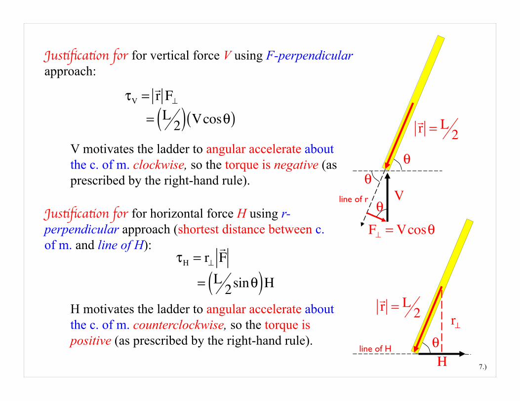
Justification for for vertical force V using F-perpendicular approach:
τV = !r F⊥
= L2( ) Vcosθ( )
V
!r = L 2
θ
F⊥ = Vcosθ
θ
V motivates the ladder to angular accelerate about the c. of m. clockwise, so the torque is negative (as prescribed by the right-hand rule).
Justification for for horizontal force H using r-perpendicular approach (shortest distance between c. of m. and line of H):
τH = r⊥!F
= L2sinθ( )H
H motivates the ladder to angular accelerate about the c. of m. counterclockwise, so the torque is positive (as prescribed by the right-hand rule).
H
!r = L 2
θr⊥
line of r
line of H

Point of order: When a force acts through the point about which a torque is taken, its torque about that point will be ZERO. Summing the torques about the center of mass, then, eliminated the torque due to . If we had been clever, though, we’d have summed the torques about contact point at the floor. In doing so, the torque due to both H and V would have been zero, which would have left us with only one unknown, the one we were looking to determine, N. Using the r-perpendicular approach on everything, that torque summation yields:
8.)
N
mLg
HV
Γ floor :∑ τN + τmLg + τmmg + τH + τV = 0
N L( )sinθ− mLg L2
cosθ⎛⎝⎜
⎞⎠⎟ − mmg 3L
4cosθ⎛
⎝⎜⎞⎠⎟ + 0 + 0 = 0
⇒ N =2mL + 3mm( )gL cosθ
4sinθ
mLgmmg
9.)
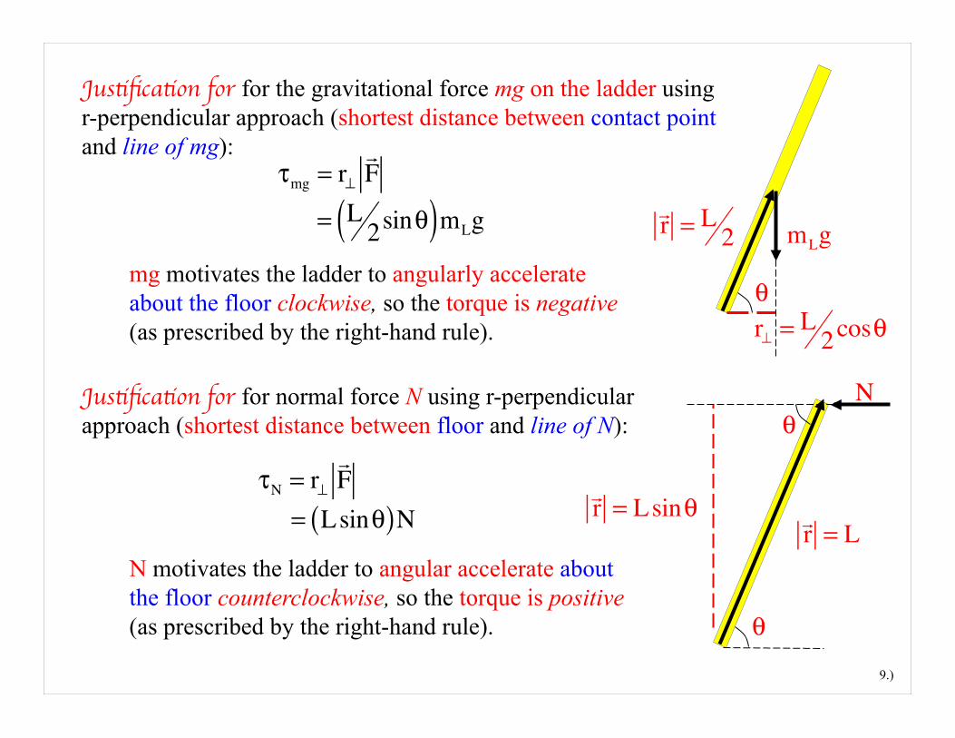
Justification for for the gravitational force mg on the ladder using r-perpendicular approach (shortest distance between contact point and line of mg):
τmg = r⊥!F
= L2sinθ( )mLg
!r = L 2
θmg motivates the ladder to angularly accelerate about the floor clockwise, so the torque is negative (as prescribed by the right-hand rule).
Justification for for normal force N using r-perpendicular approach (shortest distance between floor and line of N):
τN = r⊥!F
= Lsinθ( )NN motivates the ladder to angular accelerate about the floor counterclockwise, so the torque is positive (as prescribed by the right-hand rule).
N
!r = L
θ
mLg
r⊥ = L 2cosθ
!r = Lsinθ
θ
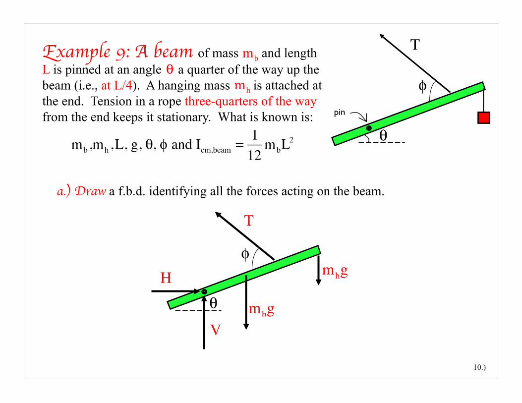
a.) Draw a f.b.d. identifying all the forces acting on the beam.
10.)
mb,mh,L, g, θ, φ and Icm,beam = 112
mbL2
T
θ
φpin
Example 9: A beam of mass and length L is pinned at an angle a quarter of the way up the beam (i.e., at L/4). A hanging mass is attached at the end. Tension in a rope three-quarters of the way from the end keeps it stationary. What is known is:
θmh
mb
φ
θ mbg
T
H
V
mhg
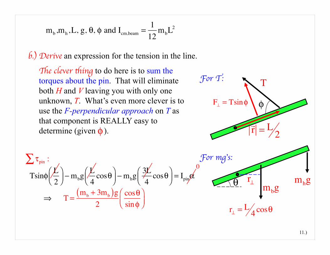
b.) Derive an expression for the tension in the line.
φ
TThe clever thing to do here is to sum the torques about the pin. That will eliminate both H and V leaving you with only one unknown, T. What’s even more clever is to use the F-perpendicular approach on T as that component is REALLY easy to determine (given ). φ
r⊥ = L 4cosθ
F⊥ = Tsinφ
θ mbgr⊥
!r = L 2
For T:
For mg’s: τpin :∑ Tsinφ L
2⎛⎝⎜
⎞⎠⎟ − mbg
L4
cosθ⎛⎝⎜
⎞⎠⎟ − mhg
3L4
cosθ⎛⎝⎜
⎞⎠⎟ = Ipinα
⇒ T =mb + 3mb( )g
2cosθsinφ
⎛⎝⎜
⎞⎠⎟
0
11.)
mhg
mb,mh,L, g, θ, φ and Icm,beam = 112
mbL2
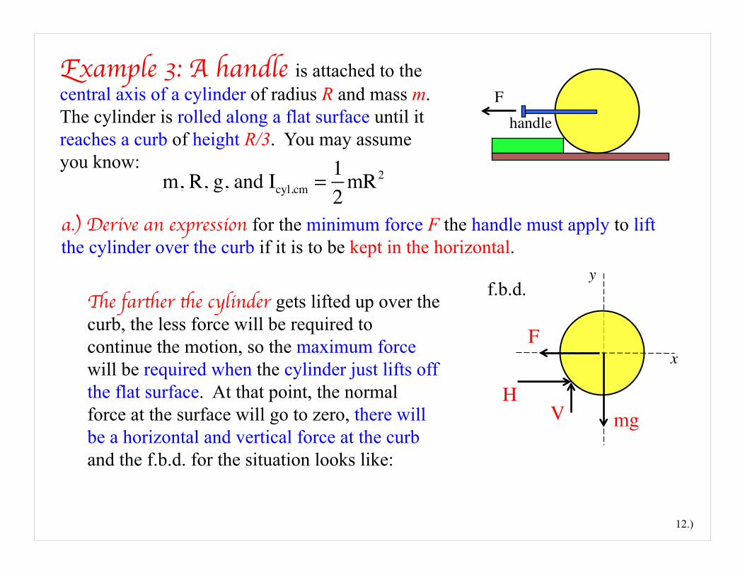
Example 3: A handle is attached to the central axis of a cylinder of radius R and mass m. The cylinder is rolled along a flat surface until it reaches a curb of height R/3. You may assume you know:
m, R, g, and Icyl,cm = 12
mR2
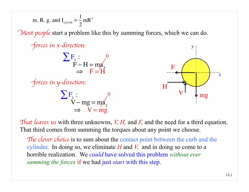
a.) Derive an expression for the minimum force F the handle must apply to lift the cylinder over the curb if it is to be kept in the horizontal.
12.)
handle
mgH
V
y
x
f.b.d.
F
The farther the cylinder gets lifted up over the curb, the less force will be required to continue the motion, so the maximum force will be required when the cylinder just lifts off the flat surface. At that point, the normal force at the surface will go to zero, there will be a horizontal and vertical force at the curb and the f.b.d. for the situation looks like:
F
m, R, g, and Icyl,cm = 12
mR2
forces in x-direction:
13.)
mgH
V
y
xF
That leaves us with three unknowns, V, H, and F, and the need for a third equation. That third comes from summing the torques about any point we choose.
Fx :∑ F − H = max ⇒ F = H
forces in y-direction:
Fy :∑ V− mg = may ⇒ V = mg
The clever choice is to sum about the contact point between the curb and the cylinder. In doing so, we eliminate H and V, and in doing so come to a horrible realization. We could have solved this problem without ever summing the forces if we had just start with this step.
Most people start a problem like this by summing forces, which we can do.
0
0
m, R, g, and Icyl,cm = 12
mR2
14.)
mg
H
V
F
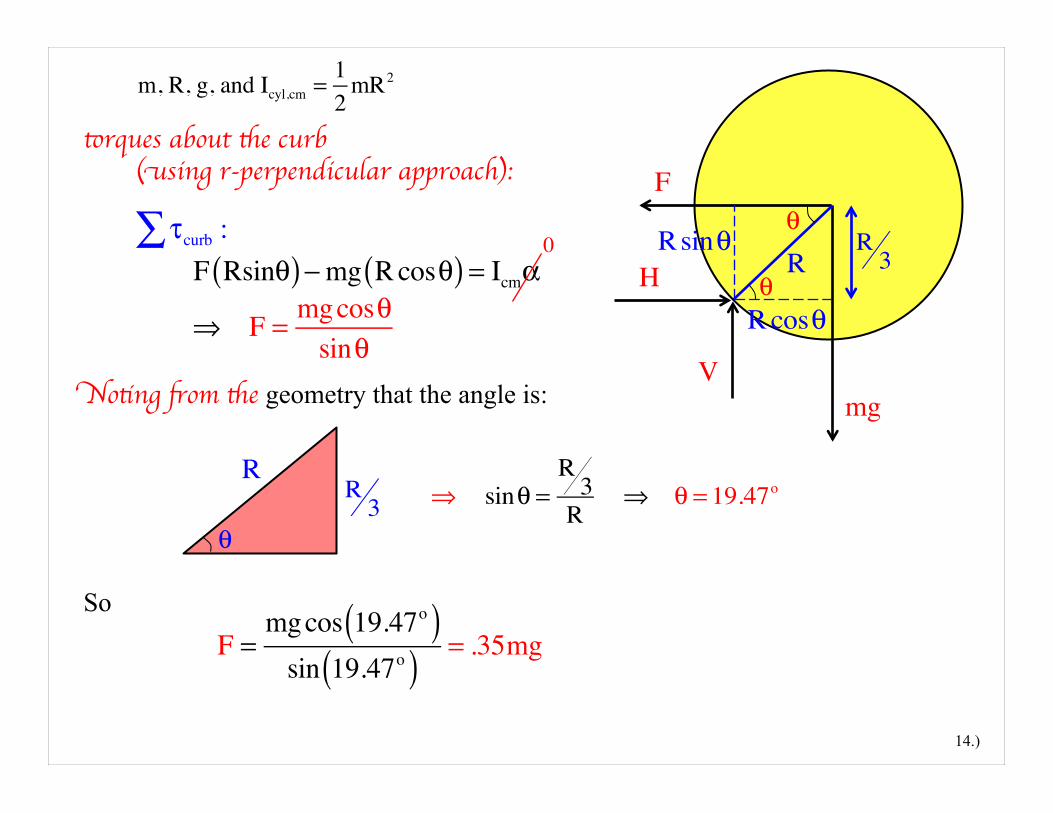
Noting from the geometry that the angle is:
τcurb :∑ F Rsinθ( )− mg R cosθ( ) = Icmα
⇒ F = mgcosθsinθ
So
RRsinθ
Rcosθ
θ
θ
R3
torques about the curb (using r-perpendicular approach):
R3
R⇒ sinθ =
R3
R ⇒ θ = 19.47o
F =mgcos 19.47o( )sin 19.47o( ) = .35mg
θ
0
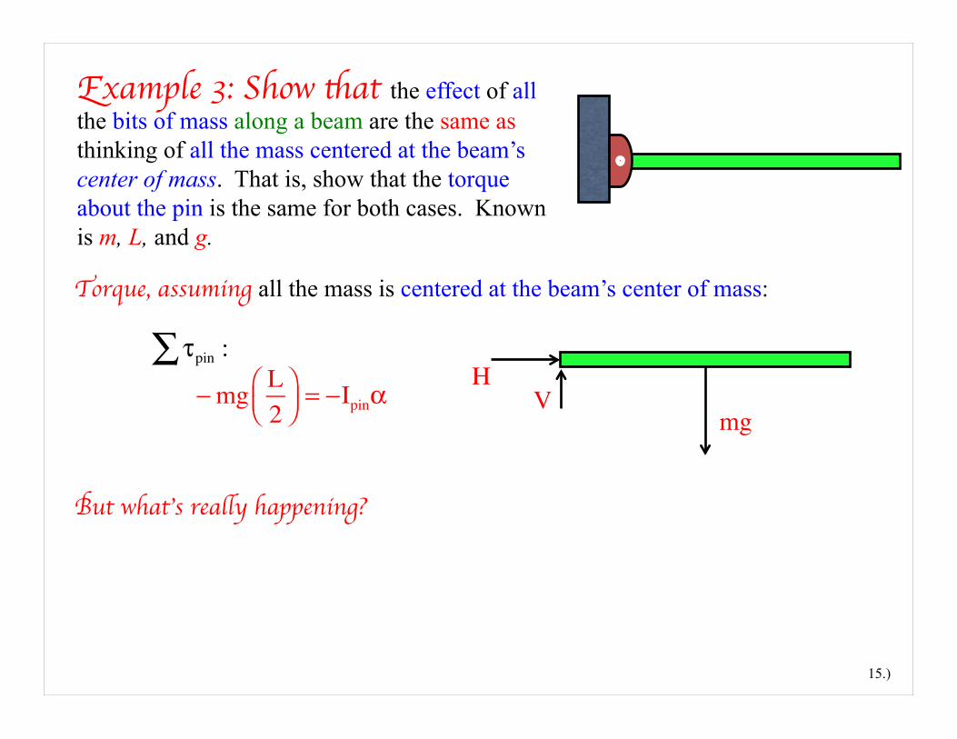
Example 3: Show that the effect of all the bits of mass along a beam are the same as thinking of all the mass centered at the beam’s center of mass. That is, show that the torque about the pin is the same for both cases. Known is m, L, and g.
Torque, assuming all the mass is centered at the beam’s center of mass:
15.)
mg
HV
But what’s really happening?
τpin :∑ − mg L
2⎛⎝⎜
⎞⎠⎟ = −Ipinα
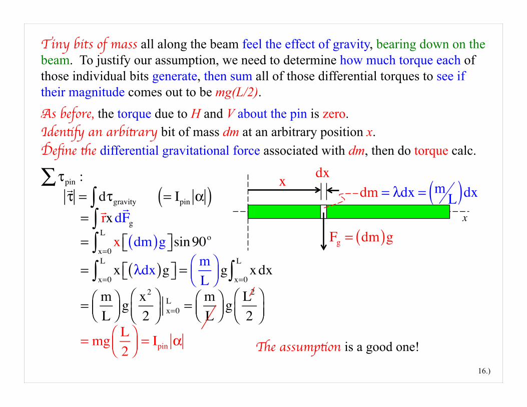
Identify an arbitrary bit of mass dm at an arbitrary position x. As before, the torque due to H and V about the pin is zero.
16.)
Tiny bits of mass all along the beam feel the effect of gravity, bearing down on the beam. To justify our assumption, we need to determine how much torque each of those individual bits generate, then sum all of those differential torques to see if their magnitude comes out to be mg(L/2).
τpin :∑ !τ = dτgravity∫ = Ipin α( )
= !rxd!Fg∫
= x dm( )g⎡⎣ ⎤⎦sin90o
x=0
L
∫ = x λdx( )g⎡⎣ ⎤⎦x=0
L
∫ = mL
⎛⎝⎜
⎞⎠⎟ g xdx
x=0
L
∫ = m
L⎛⎝⎜
⎞⎠⎟ g x2
2⎛⎝⎜
⎞⎠⎟ x=0
L = mL
⎛⎝⎜
⎞⎠⎟ g L2
2⎛⎝⎜
⎞⎠⎟
= mg L2
⎛⎝⎜
⎞⎠⎟ = Ipin α
x
x dx
Fg = dm( )g
The assumption is a good one!
dm = λdx = mL( )dx
Define the differential gravitational force associated with dm, then do torque calc.