Embed Size (px)
DESCRIPTION
thermodynamics
Citation preview

Methodology
• Specify appropriate form of the heat equation.
• Solve for the temperature distribution.
• Apply Fourier’s law to determine the heat flux.
Simplest Case: One-Dimensional, Steady-State Conduction with No Thermal Energy Generation.
• Common Geometries:
– The Plane Wall: Described in rectangular (x) coordinate. Area
perpendicular to direction of heat transfer is constant (independent of x).
– The Tube Wall: Radial conduction through tube wall.
– The Spherical Shell: Radial conduction through shell wall.
Methodology of a Conduction Analysis
Plane Wall
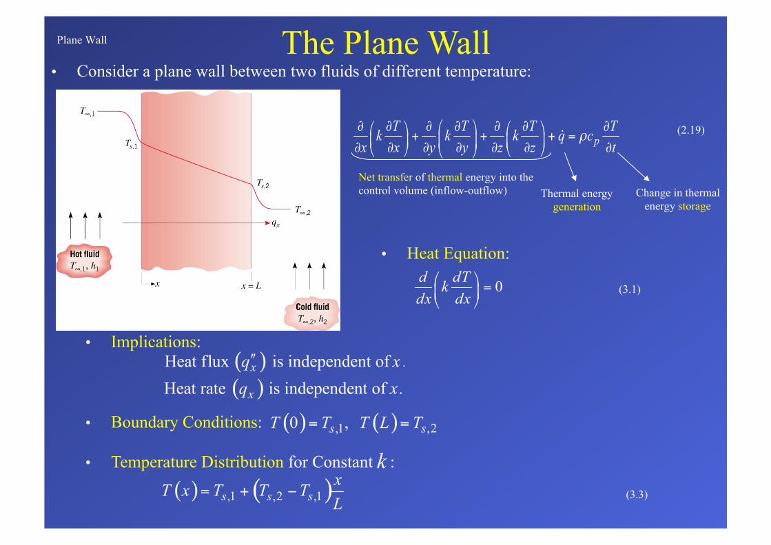
• Consider a plane wall between two fluids of different temperature: The Plane Wall
• Implications:
(3.1)
• Heat Equation:
• Boundary Conditions:
• Temperature Distribution for Constant :
(3.3)
Net transfer of thermal energy into the control volume (inflow-outflow)
(2.19)
Thermal energy generation
Change in thermal energy storage
Plane Wall (cont.)
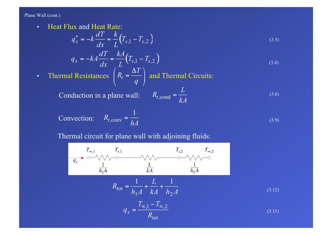
• Heat Flux and Heat Rate:
(3.5)
(3.4)
• Thermal Resistances and Thermal Circuits:
Conduction in a plane wall: (3.6)
Convection: (3.9)
Thermal circuit for plane wall with adjoining fluids:
(3.12)
(3.11)
Plane Wall (cont.)
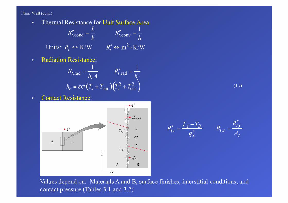
• Thermal Resistance for Unit Surface Area:
• Radiation Resistance:
(1.9)
• Contact Resistance:
Values depend on: Materials A and B, surface finishes, interstitial conditions, and contact pressure (Tables 3.1 and 3.2)
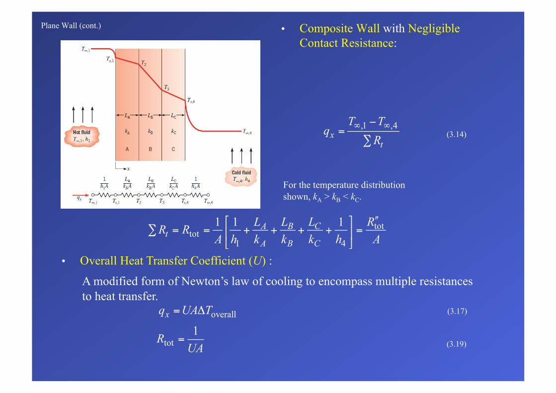
Plane Wall (cont.) • Composite Wall with Negligible Contact Resistance:
(3.14)
• Overall Heat Transfer Coefficient (U) :
A modified form of Newton’s law of cooling to encompass multiple resistances to heat transfer.
(3.17)
(3.19)
For the temperature distribution shown, kA > kB < kC.
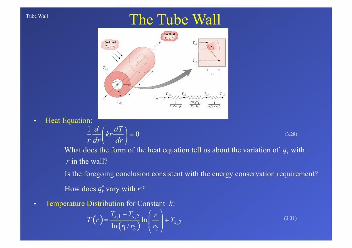
Tube Wall
• Heat Equation:
The Tube Wall
(3.28)
Is the foregoing conclusion consistent with the energy conservation requirement?
How does vary with ?
What does the form of the heat equation tell us about the variation of with r in the wall?
• Temperature Distribution for Constant :
(3.31)
Tube Wall (cont.)
• Heat Flux and Heat Rate:
(3.32)
• Conduction Resistance:
(3.33)
Why doesn’t a surface area appear in the expressions for the thermal resistance?
[W/m2]
[W/m]
[W]
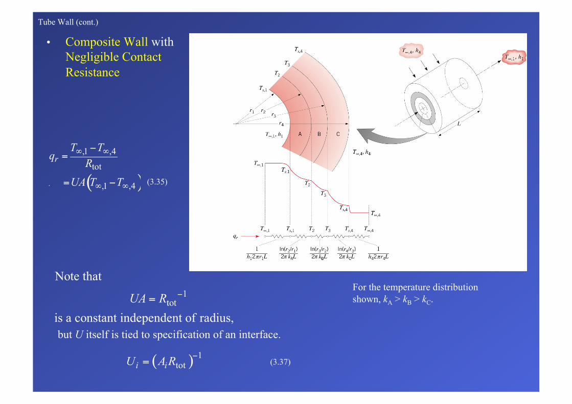
Tube Wall (cont.)
• Composite Wall with Negligible Contact
Resistance
(3.35)
but U itself is tied to specification of an interface.
(3.37)
For the temperature distribution shown, kA > kB > kC.
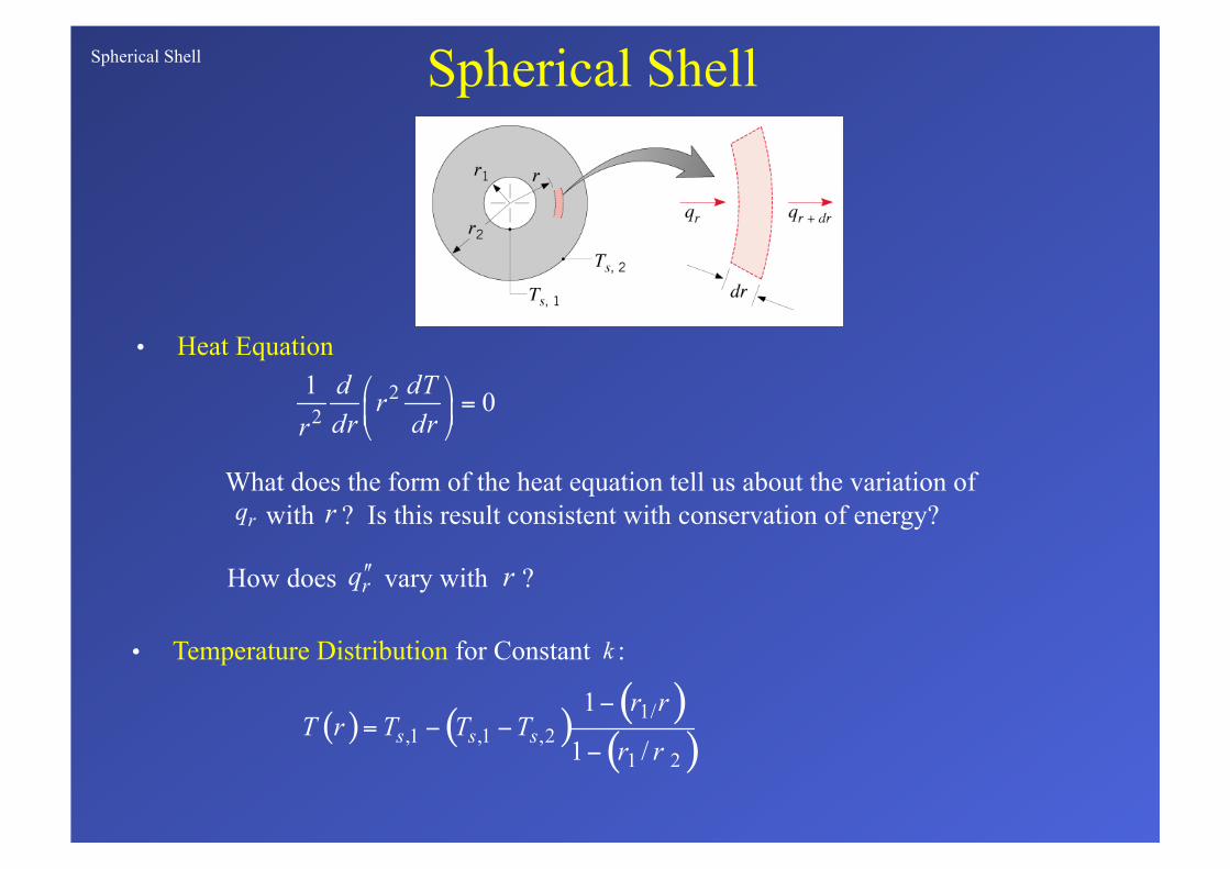
Spherical Shell
• Heat Equation
Spherical Shell
What does the form of the heat equation tell us about the variation of with ? Is this result consistent with conservation of energy?
How does vary with ?
• Temperature Distribution for Constant :
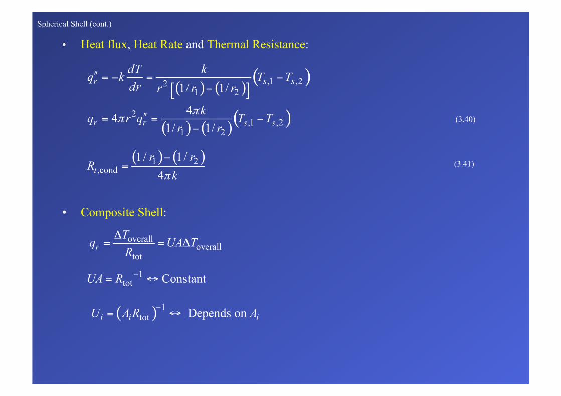
Spherical Shell (cont.)
• Heat flux, Heat Rate and Thermal Resistance:
(3.40)
• Composite Shell:
(3.41)
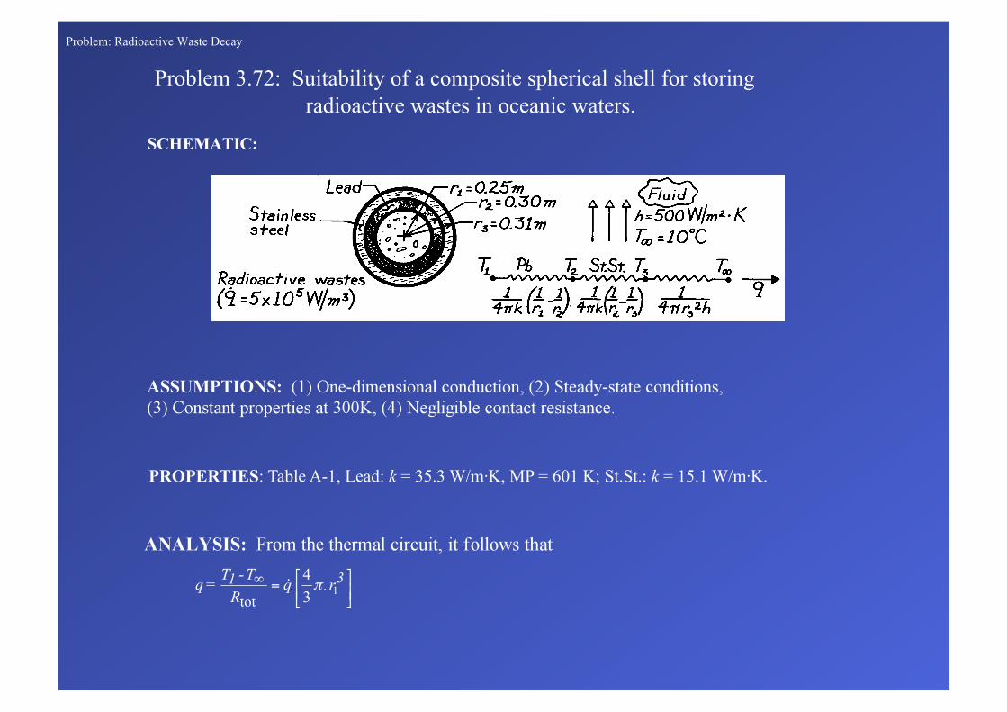
Problem: Radioactive Waste Decay
Problem 3.72: Suitability of a composite spherical shell for storing radioactive wastes in oceanic waters.
PROPERTIES: Table A-1, Lead: k = 35.3 W/m·K, MP = 601 K; St.St.: k = 15.1 W/m·K.

Problem: Radioactive Waste Decay (cont..)
<
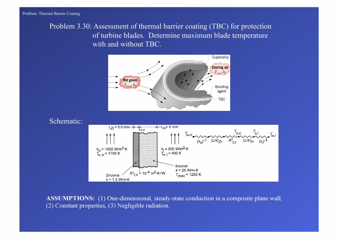
Problem: Thermal Barrier Coating
Problem 3.30: Assessment of thermal barrier coating (TBC) for protection of turbine blades. Determine maximum blade temperature with and without TBC.
Schematic:

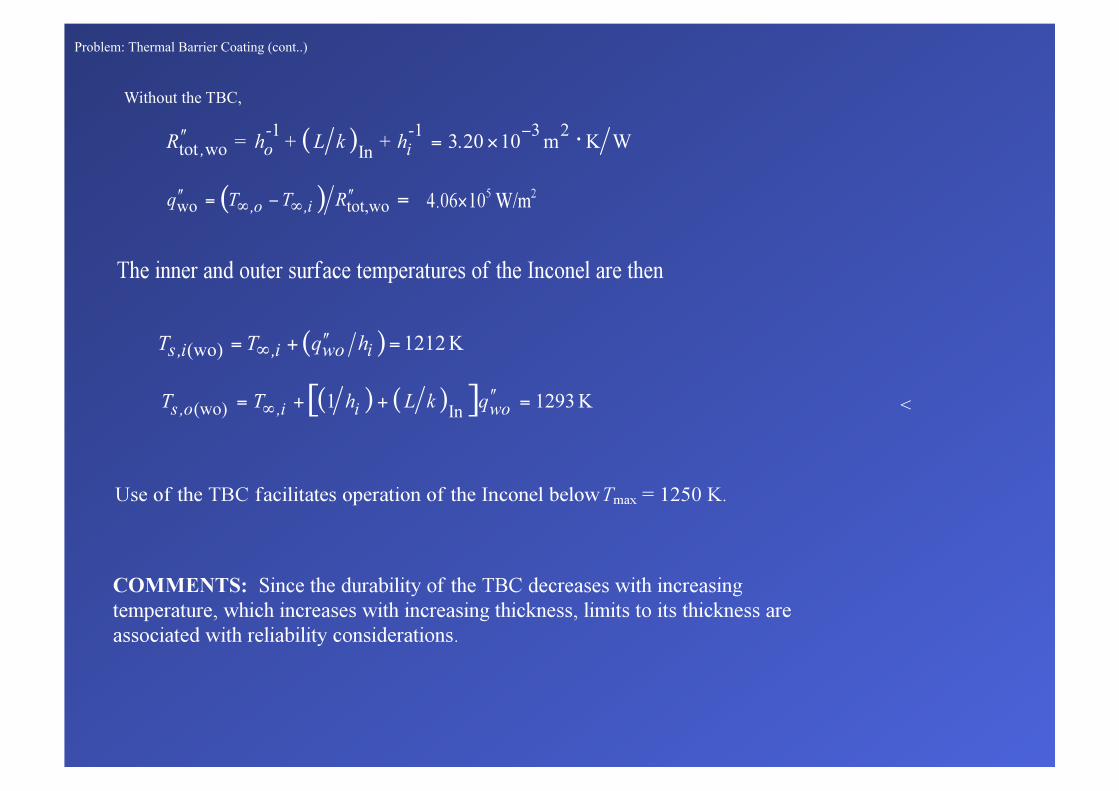
Problem: Thermal Barrier Coating (cont..)
With a heat flux of
the inner and outer surface temperatures of the Inconel are
ANALYSIS: For a unit area, the total thermal resistance with the TBC is
<
Problem: Thermal Barrier Coating (cont..)
Without the TBC,
<
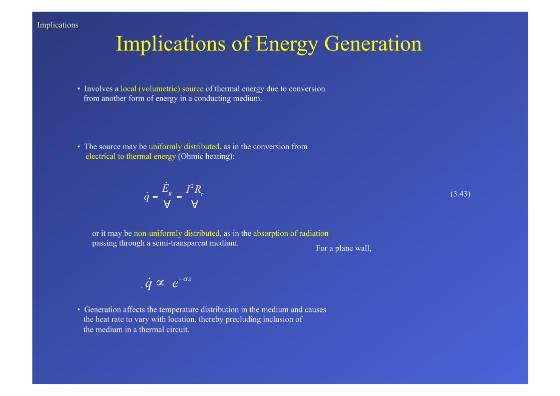
Implications of Energy Generation
• Involves a local (volumetric) source of thermal energy due to conversion from another form of energy in a conducting medium.
• The source may be uniformly distributed, as in the conversion from electrical to thermal energy (Ohmic heating):
(3.43)
or it may be non-uniformly distributed, as in the absorption of radiation passing through a semi-transparent medium.
• Generation affects the temperature distribution in the medium and causes the heat rate to vary with location, thereby precluding inclusion of the medium in a thermal circuit.
For a plane wall,
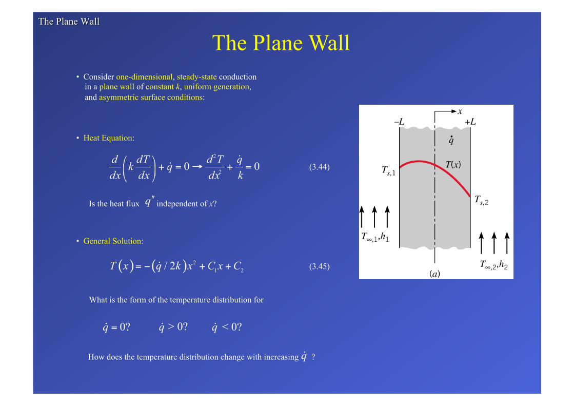
The Plane Wall • Consider one-dimensional, steady-state conduction in a plane wall of constant k, uniform generation, and asymmetric surface conditions:
• Heat Equation:
(3.44)
Is the heat flux independent of x?
• General Solution:
What is the form of the temperature distribution for
How does the temperature distribution change with increasing ?
(3.45)
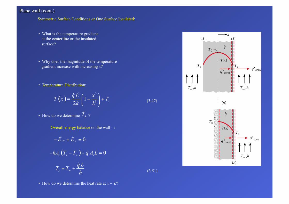
Symmetric Surface Conditions or One Surface Insulated:
• What is the temperature gradient at the centerline or the insulated surface?
• Why does the magnitude of the temperature gradient increase with increasing x?
• Temperature Distribution:
(3.47)
Overall energy balance on the wall →
(3.51)
• How do we determine the heat rate at x = L?
• How do we determine ?
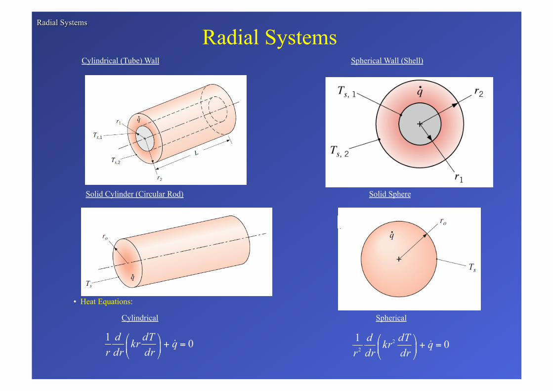
Radial Systems
• Heat Equations:
Cylindrical Spherical
Cylindrical (Tube) Wall Spherical Wall (Shell)
Solid Cylinder (Circular Rod) Solid Sphere
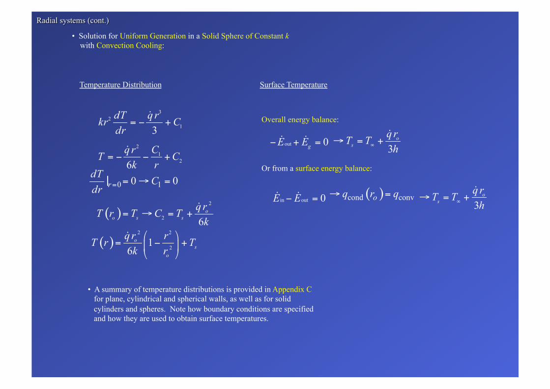
Temperature Distribution Surface Temperature
Overall energy balance:
Or from a surface energy balance:
• Solution for Uniform Generation in a Solid Sphere of Constant k with Convection Cooling:
• A summary of temperature distributions is provided in Appendix C for plane, cylindrical and spherical walls, as well as for solid cylinders and spheres. Note how boundary conditions are specified and how they are used to obtain surface temperatures.
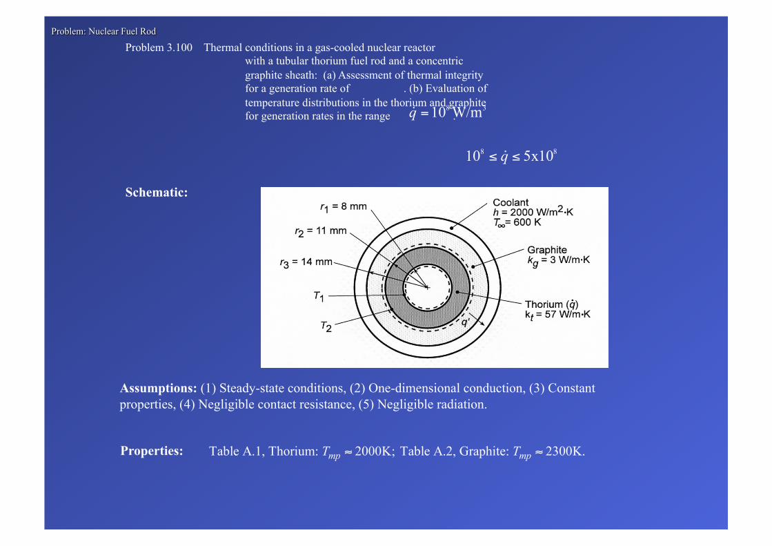
Problem 3.100 Thermal conditions in a gas-cooled nuclear reactor with a tubular thorium fuel rod and a concentric graphite sheath: (a) Assessment of thermal integrity for a generation rate of . (b) Evaluation of temperature distributions in the thorium and graphite for generation rates in the range .
Assumptions: (1) Steady-state conditions, (2) One-dimensional conduction, (3) Constant properties, (4) Negligible contact resistance, (5) Negligible radiation.
Properties:
Schematic:

Analysis: (a) The outer surface temperature of the fuel, T2 , may be determined from the rate equation
where
The heat rate may be determined by applying an energy balance to a control surface about the fuel element,
Since the interior surface of the element is essentially adiabatic, it follows that
Hence,
With zero heat flux at the inner surface of the fuel element, Eq. C.14 yields
or, per unit length,

Since T1 and T2 are well below the melting points of thorium and graphite, the prescribed operating condition is acceptable.
(b) The solution for the temperature distribution in a cylindrical wall with generation is
(C.2)
Boundary conditions at r1 and r2 are used to determine T1 and T 2 .
(C.14)
(C.17)
(3.37)
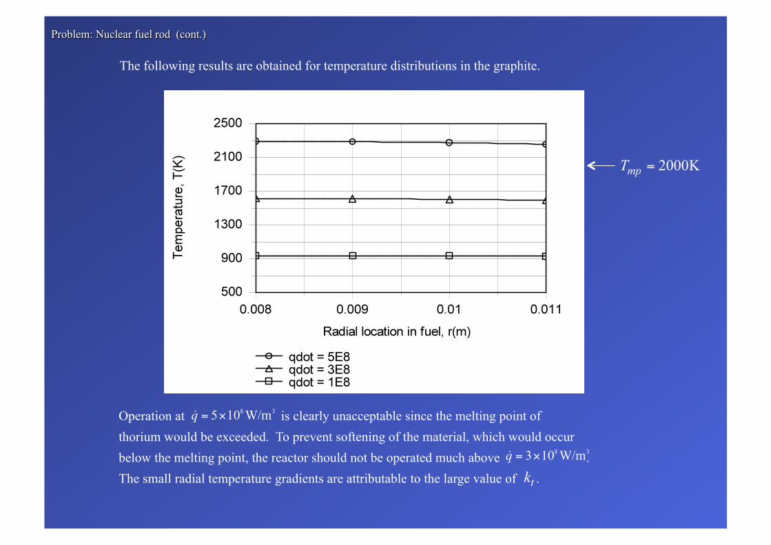
The following results are obtained for temperature distributions in the graphite.
Operation at is clearly unacceptable since the melting point of thorium would be exceeded. To prevent softening of the material, which would occur below the melting point, the reactor should not be operated much above . The small radial temperature gradients are attributable to the large value of .
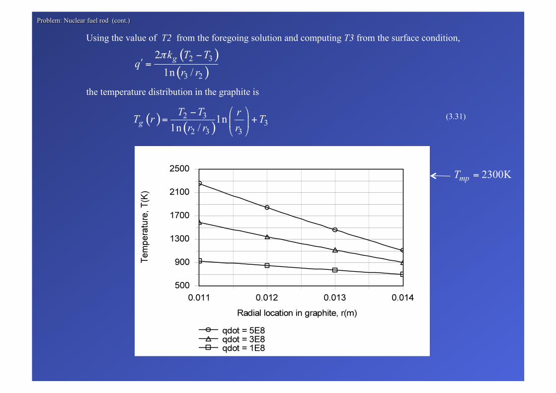
the temperature distribution in the graphite is
(3.31)
Using the value of T2 from the foregoing solution and computing T3 from the surface condition,
Comments: (i) What effect would a contact resistance at the thorium/graphite interface have on temperatures in the fuel element and on the maximum allowable value of ?
Operation at is problematic for the graphite. Larger temperature gradients are due to the small value of .
What would be the influence of such effect on temperatures in the fuel element and the maximum allowable value of ?
(ii) Referring to the schematic, where might radiation effects be significant?