Embed Size (px)
Citation preview
General Informationwww.vishay.com Vishay Cera-Mite
Revision: 21-Aug-17 1 Document Number: 23140For technical questions, contact: [email protected]
THIS DOCUMENT IS SUBJECT TO CHANGE WITHOUT NOTICE. THE PRODUCTS DESCRIBED HEREIN AND THIS DOCUMENTARE SUBJECT TO SPECIFIC DISCLAIMERS, SET FORTH AT www.vishay.com/doc?91000
Ceramic DC Disc, RFI, and Safety Capacitors
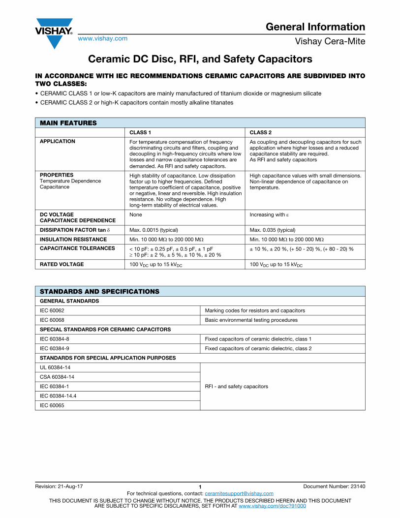
IN ACCORDANCE WITH IEC RECOMMENDATIONS CERAMIC CAPACITORS ARE SUBDIVIDED INTO TWO CLASSES:• CERAMIC CLASS 1 or low-K capacitors are mainly manufactured of titanium dioxide or magnesium silicate
• CERAMIC CLASS 2 or high-K capacitors contain mostly alkaline titanates
MAIN FEATURESCLASS 1 CLASS 2
APPLICATION For temperature compensation of frequency discriminating circuits and filters, coupling and decoupling in high-frequency circuits where low losses and narrow capacitance tolerances aredemanded. As RFI and safety capacitors.
As coupling and decoupling capacitors for such application where higher losses and a reduced capacitance stability are required. As RFI and safety capacitors
PROPERTIESTemperature Dependence Capacitance
High stability of capacitance. Low dissipation factor up to higher frequencies. Defined temperature coefficient of capacitance, positive or negative, linear and reversible. High insulation resistance. No voltage dependence. High long-term stability of electrical values.
High capacitance values with small dimensions. Non-linear dependence of capacitance on temperature.
DC VOLTAGE CAPACITANCE DEPENDENCE
None Increasing with
DISSIPATION FACTOR tan Max. 0.0015 (typical) Max. 0.035 (typical)
INSULATION RESISTANCE Min. 10 000 M to 200 000 M Min. 10 000 M to 200 000 M
CAPACITANCE TOLERANCES < 10 pF: ± 0.25 pF, ± 0.5 pF, ± 1 pF 10 pF: ± 2 %, ± 5 %, ± 10 %, ± 20 %
± 10 %, ± 20 %, (+ 50 - 20) %, (+ 80 - 20) %
RATED VOLTAGE 100 VDC up to 15 kVDC 100 VDC up to 15 kVDC
STANDARDS AND SPECIFICATIONSGENERAL STANDARDS
IEC 60062 Marking codes for resistors and capacitors
IEC 60068 Basic environmental testing procedures
SPECIAL STANDARDS FOR CERAMIC CAPACITORS
IEC 60384-8 Fixed capacitors of ceramic dielectric, class 1
IEC 60384-9 Fixed capacitors of ceramic dielectric, class 2
STANDARDS FOR SPECIAL APPLICATION PURPOSES
UL 60384-14
RFI - and safety capacitors
CSA 60384-14
IEC 60384-1
IEC 60384-14.4
IEC 60065
General Informationwww.vishay.com Vishay Cera-Mite
Revision: 21-Aug-17 2 Document Number: 23140For technical questions, contact: [email protected]
THIS DOCUMENT IS SUBJECT TO CHANGE WITHOUT NOTICE. THE PRODUCTS DESCRIBED HEREIN AND THIS DOCUMENTARE SUBJECT TO SPECIFIC DISCLAIMERS, SET FORTH AT www.vishay.com/doc?91000
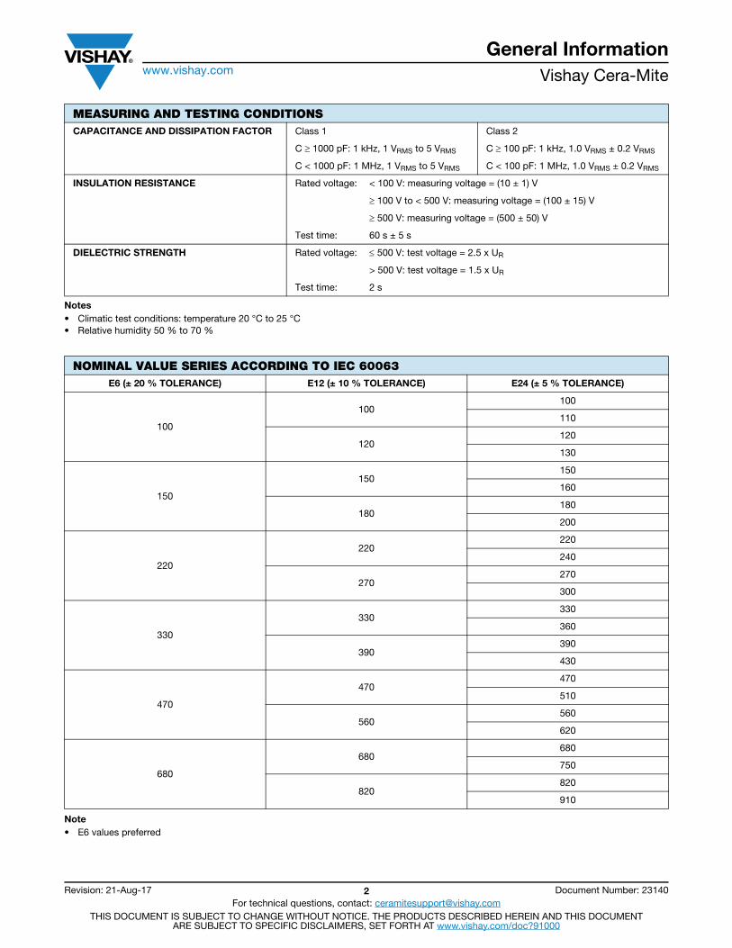
Notes• Climatic test conditions: temperature 20 °C to 25 °C• Relative humidity 50 % to 70 %
Note• E6 values preferred
MEASURING AND TESTING CONDITIONSCAPACITANCE AND DISSIPATION FACTOR Class 1 Class 2
C 1000 pF: 1 kHz, 1 VRMS to 5 VRMS C 100 pF: 1 kHz, 1.0 VRMS ± 0.2 VRMS
C < 1000 pF: 1 MHz, 1 VRMS to 5 VRMS C < 100 pF: 1 MHz, 1.0 VRMS ± 0.2 VRMS
INSULATION RESISTANCE Rated voltage: < 100 V: measuring voltage = (10 ± 1) V
100 V to < 500 V: measuring voltage = (100 ± 15) V
500 V: measuring voltage = (500 ± 50) V
Test time: 60 s ± 5 s
DIELECTRIC STRENGTH Rated voltage: 500 V: test voltage = 2.5 x UR
> 500 V: test voltage = 1.5 x UR
Test time: 2 s
NOMINAL VALUE SERIES ACCORDING TO IEC 60063E6 (± 20 % TOLERANCE) E12 (± 10 % TOLERANCE) E24 (± 5 % TOLERANCE)
100
100100
110
120120
130
150
150150
160
180180
200
220
220220
240
270270
300
330
330330
360
390390
430
470
470470
510
560560
620
680
680680
750
820820
910
General Informationwww.vishay.com Vishay Cera-Mite
Revision: 21-Aug-17 3 Document Number: 23140For technical questions, contact: [email protected]
THIS DOCUMENT IS SUBJECT TO CHANGE WITHOUT NOTICE. THE PRODUCTS DESCRIBED HEREIN AND THIS DOCUMENTARE SUBJECT TO SPECIFIC DISCLAIMERS, SET FORTH AT www.vishay.com/doc?91000
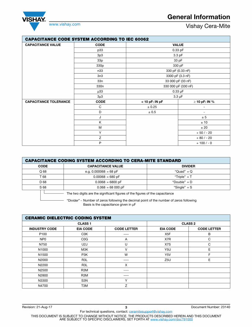
CAPACITANCE CODE SYSTEM ACCORDING TO IEC 60062CAPACITANCE VALUE CODE VALUE
p33 0.33 pF
3p3 3.3 pF
33p 33 pF
330p 330 pF
n33 330 pF (0.33 nF)
3n3 3300 pF (3.3 nF)
33n 33 000 pF (33 nF)
330n 330 000 pF (330 nF)
μ33 0.33 μF
3μ3 3.3 μF
CAPACITANCE TOLERANCE CODE < 10 pF: IN pF 10 pF: IN %
C ± 0.25 -
D ± 0.5 -
J ± 5
K ± 10
M ± 20
Y + 50 / - 20
Z + 80 / - 20
P + 100 / - 0
CAPACITANCE CODING SYSTEM ACCORDING TO CERA-MITE STANDARDCODE CAPACITANCE VALUE DIVIDER
Q 68 e.g. 0.000068 = 68 pF “Quad” = Q
T 68 0.00068 = 680 pF “Triple” = T
D 68 0.0068 = 6800 pF “Double” = D
S 68 0.068 = 68 000 pF “Single” = S
The two digits are the significant figures of the figures of the capacitance
“Divider” - Number of zeros following the decimal point of the number of zeros followingBasis is the capacitance given in μF
CERAMIC DIELECTRIC CODING SYSTEMCLASS 1 CLASS 2
INDUSTRY CODE EIA CODE CODE LETTER EIA CODE CODE LETTER
P100 C0K ---- X5F B
NP0 C0G A X7R C
N750 U2J U X7S C
N1000 M3K V Y5U E
N1500 P3K W Y5V F
N2000 R3L ---- Z5U E
N2200 R3L X
N2500 R3M ----
N2800 R3M ----
N3300 S3N Y
N4700 T3M Z
General Informationwww.vishay.com Vishay Cera-Mite
Revision: 21-Aug-17 4 Document Number: 23140For technical questions, contact: [email protected]
THIS DOCUMENT IS SUBJECT TO CHANGE WITHOUT NOTICE. THE PRODUCTS DESCRIBED HEREIN AND THIS DOCUMENTARE SUBJECT TO SPECIFIC DISCLAIMERS, SET FORTH AT www.vishay.com/doc?91000
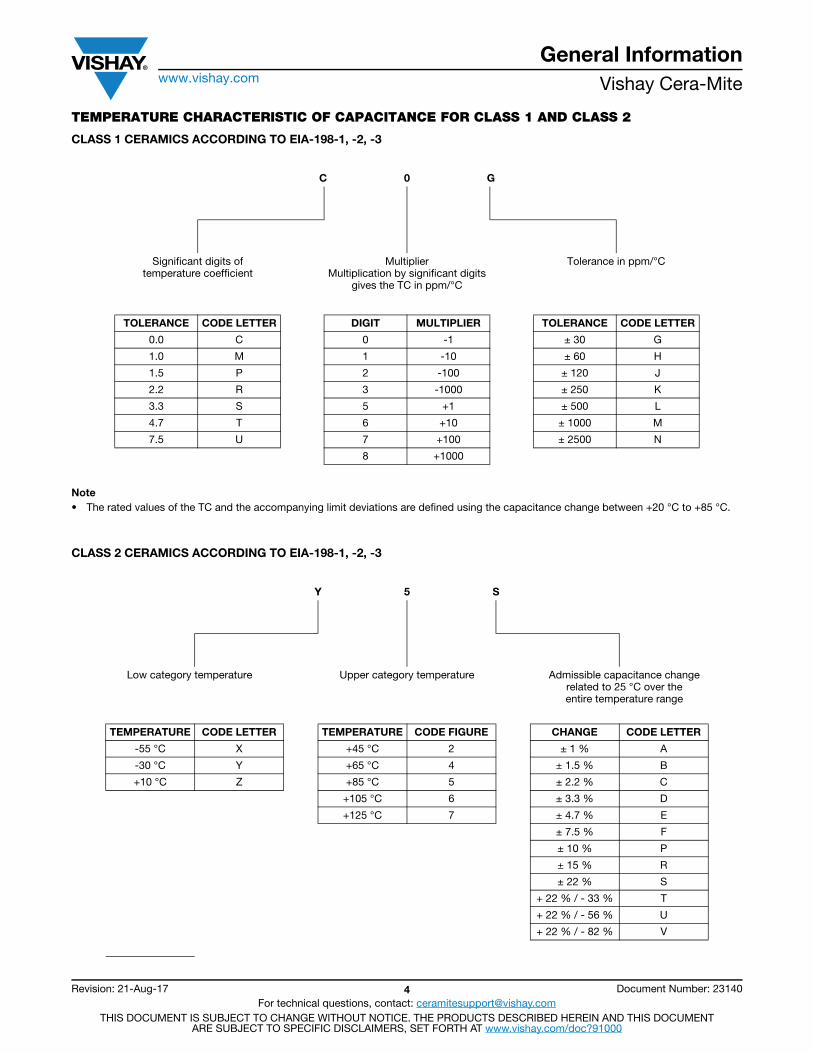
TEMPERATURE CHARACTERISTIC OF CAPACITANCE FOR CLASS 1 AND CLASS 2
CLASS 1 CERAMICS ACCORDING TO EIA-198-1, -2, -3
Note• The rated values of the TC and the accompanying limit deviations are defined using the capacitance change between +20 °C to +85 °C.
CLASS 2 CERAMICS ACCORDING TO EIA-198-1, -2, -3
C 0 G
Significant digits oftemperature coefficient
MultiplierMultiplication by significant digits
gives the TC in ppm/°C
Tolerance in ppm/°C
TOLERANCE CODE LETTER DIGIT MULTIPLIER TOLERANCE CODE LETTER
0.0 C 0 -1 ± 30 G
1.0 M 1 -10 ± 60 H
1.5 P 2 -100 ± 120 J
2.2 R 3 -1000 ± 250 K
3.3 S 5 +1 ± 500 L
4.7 T 6 +10 ± 1000 M
7.5 U 7 +100 ± 2500 N
8 +1000
Y 5 S
Low category temperature Upper category temperature Admissible capacitance changerelated to 25 °C over theentire temperature range
TEMPERATURE CODE LETTER TEMPERATURE CODE FIGURE CHANGE CODE LETTER
-55 °C X +45 °C 2 ± 1 % A
-30 °C Y +65 °C 4 ± 1.5 % B
+10 °C Z +85 °C 5 ± 2.2 % C
+105 °C 6 ± 3.3 % D
+125 °C 7 ± 4.7 % E
± 7.5 % F
± 10 % P
± 15 % R
± 22 % S
+ 22 % / - 33 % T
+ 22 % / - 56 % U
+ 22 % / - 82 % V
General Informationwww.vishay.com Vishay Cera-Mite
Revision: 21-Aug-17 5 Document Number: 23140For technical questions, contact: [email protected]
THIS DOCUMENT IS SUBJECT TO CHANGE WITHOUT NOTICE. THE PRODUCTS DESCRIBED HEREIN AND THIS DOCUMENTARE SUBJECT TO SPECIFIC DISCLAIMERS, SET FORTH AT www.vishay.com/doc?91000
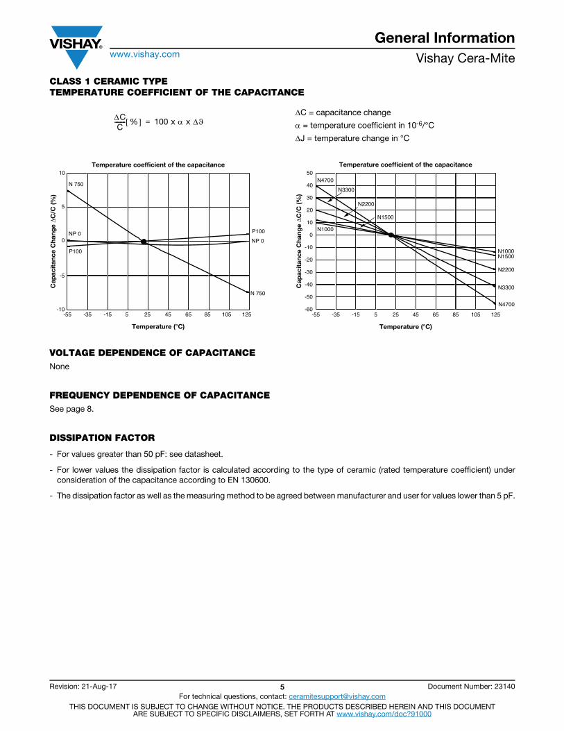
CLASS 1 CERAMIC TYPETEMPERATURE COEFFICIENT OF THE CAPACITANCE
C = capacitance change
= temperature coefficient in 10-6/°C
J = temperature change in °C
VOLTAGE DEPENDENCE OF CAPACITANCENone
FREQUENCY DEPENDENCE OF CAPACITANCESee page 8.
DISSIPATION FACTOR
- For values greater than 50 pF: see datasheet.
- For lower values the dissipation factor is calculated according to the type of ceramic (rated temperature coefficient) under consideration of the capacitance according to EN 130600.
- The dissipation factor as well as the measuring method to be agreed between manufacturer and user for values lower than 5 pF.
CC
-------- % 100 x x =
Temperature (°C)
Cap
acit
ance
Cha
nge ΔC
/C (%
)
10
5
0
-10125 105 85 65 45 25 5 -15 -35 -55
-5
N 750
NP 0
P100
P100
NP 0
N 750
Temperature coefficient of the capacitance
Temperature (°C)
Cap
acit
ance
Cha
nge ΔC
/C (%
)
125105856545255-15-35-55
50
40
-10
-60
-30
N4700
N1500
N1500
N4700
30
20
10
0
-20
-40
-50
N1000
N1000
N2200
N2200
N3300
N3300
Temperature coefficient of the capacitance
General Informationwww.vishay.com Vishay Cera-Mite
Revision: 21-Aug-17 6 Document Number: 23140For technical questions, contact: [email protected]
THIS DOCUMENT IS SUBJECT TO CHANGE WITHOUT NOTICE. THE PRODUCTS DESCRIBED HEREIN AND THIS DOCUMENTARE SUBJECT TO SPECIFIC DISCLAIMERS, SET FORTH AT www.vishay.com/doc?91000
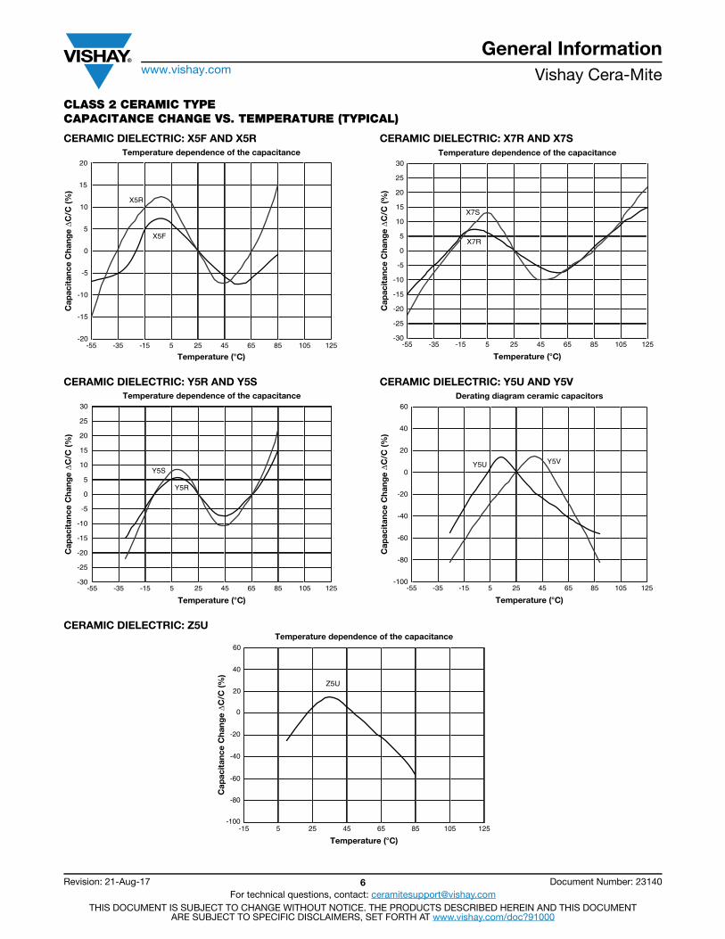
CLASS 2 CERAMIC TYPECAPACITANCE CHANGE VS. TEMPERATURE (TYPICAL)
CERAMIC DIELECTRIC: X5F AND X5R
CERAMIC DIELECTRIC: Y5R AND Y5S
CERAMIC DIELECTRIC: X7R AND X7S
CERAMIC DIELECTRIC: Y5U AND Y5V
CERAMIC DIELECTRIC: Z5U
Temperature (°C)
Cap
acit
ance
Cha
nge ΔC
/C (%
)
20
15
10
5
0
-20
-15
-10
-5
X5R
X5F
125105856545255-15-35-55
Temperature dependence of the capacitance
Temperature (°C)
Cap
acit
ance
Cha
nge ΔC
/C (%
)
125105856545255-15-35-55
Temperature dependence of the capacitance30
15
10
5
0
-30
-20
-10
-5
25
20
-15
-25
Y5S
Y5R
125105856545255-15-35-55
30
15
10
5
0
-30
-20
-10
-5
25
20
-15
-25
X7S
X7R
Temperature (°C)
Cap
acit
ance
Cha
nge ΔC
/C (%
)
Temperature dependence of the capacitance
125105856545255-15-35-55
40
20
-60
-40
-20
60
-80
-100
Y5U Y5V
0
Temperature (°C)
Cap
acit
ance
Cha
nge ΔC
/C (%
)Derating diagram ceramic capacitors
40
20
125105856545255-15
-60
-40
-20
60
-80
-100
Z5U
0
Temperature (°C)
Cap
acit
ance
Cha
nge ΔC
/C (%
)
Temperature dependence of the capacitance
General Informationwww.vishay.com Vishay Cera-Mite
Revision: 21-Aug-17 7 Document Number: 23140For technical questions, contact: [email protected]
THIS DOCUMENT IS SUBJECT TO CHANGE WITHOUT NOTICE. THE PRODUCTS DESCRIBED HEREIN AND THIS DOCUMENTARE SUBJECT TO SPECIFIC DISCLAIMERS, SET FORTH AT www.vishay.com/doc?91000
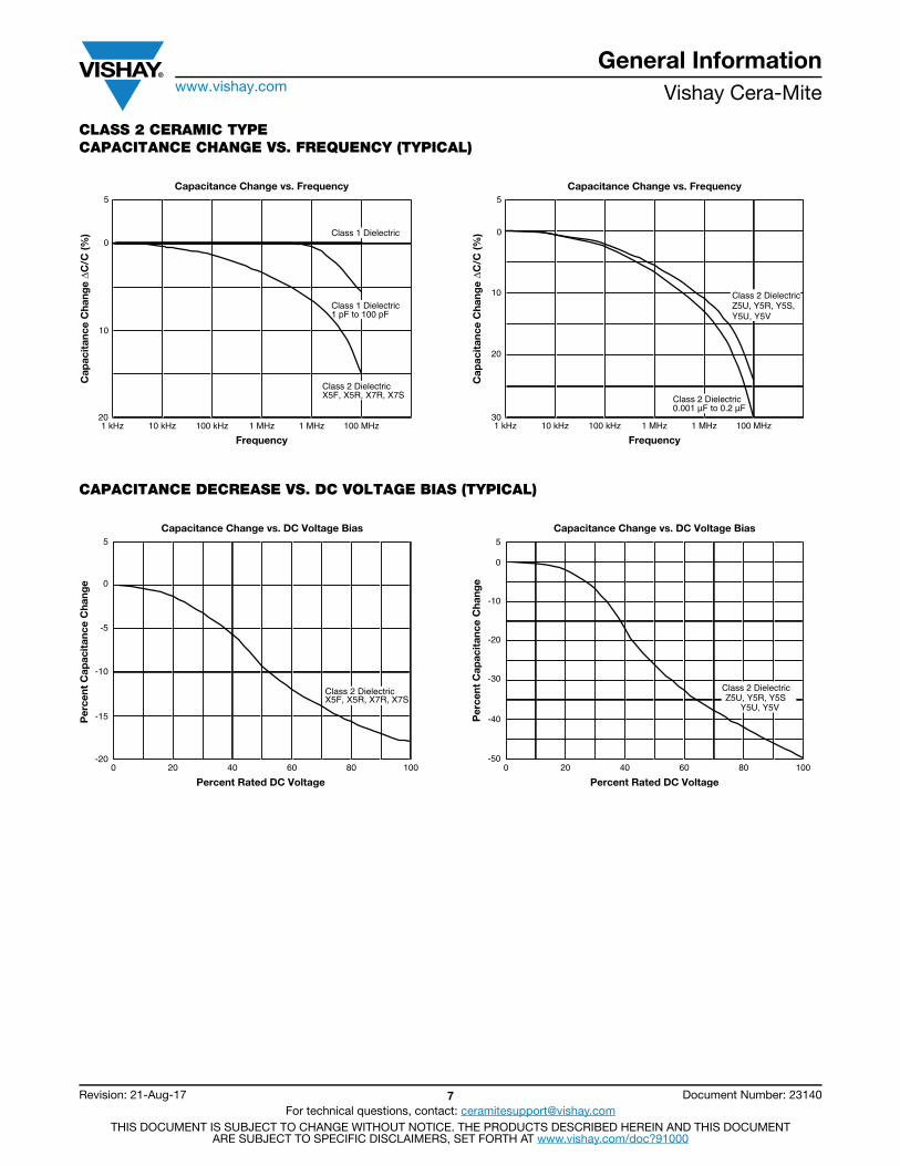
CLASS 2 CERAMIC TYPECAPACITANCE CHANGE VS. FREQUENCY (TYPICAL)
CAPACITANCE DECREASE VS. DC VOLTAGE BIAS (TYPICAL)
Frequency
Cap
acit
ance
Cha
nge ΔC
/C (%
)
Capacitance Change vs. Frequency5
0
10
100 MHz 1 MHz 1 MHz 100 kHz 10 kHz 1 kHz20
Class 1 Dielectric
Class 1 Dielectric 1 pF to 100 pF
Class 2 Dielectric X5F, X5R, X7R, X7S
Frequency
Cap
acit
ance
Cha
nge ΔC
/C (%
)
100 MHz 1 MHz 1 MHz 100 kHz 10 kHz 1 kHz
5
0
20
30
10
Class 2 Dielectric0.001 µF to 0.2 µF
Class 2 DielectricZ5U, Y5R, Y5S,Y5U, Y5V
Capacitance Change vs. Frequency
Percent Rated DC Voltage
Per
cent
Cap
acit
ance
Cha
nge
Capacitance Change vs. DC Voltage Bias5
0
-15
80 60 40 20 1000 -20
-10
-5
Class 2 Dielectric X5F, X5R, X7R, X7S
Percent Rated DC Voltage
Per
cent
Cap
acit
ance
Cha
nge
Capacitance Change vs. DC Voltage Bias
80 60 40 20 0 100
Class 2 Dielectric Z5U, Y5R, Y5S Y5U, Y5V
5
0
-30
-40
-20
-10
-50
General Informationwww.vishay.com Vishay Cera-Mite
Revision: 21-Aug-17 8 Document Number: 23140For technical questions, contact: [email protected]
THIS DOCUMENT IS SUBJECT TO CHANGE WITHOUT NOTICE. THE PRODUCTS DESCRIBED HEREIN AND THIS DOCUMENTARE SUBJECT TO SPECIFIC DISCLAIMERS, SET FORTH AT www.vishay.com/doc?91000
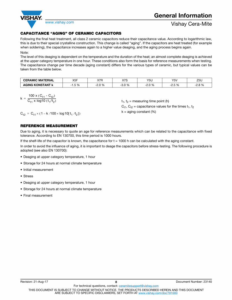
CAPACITANCE “AGING” OF CERAMIC CAPACITORSFollowing the final heat treatment, all class 2 ceramic capacitors reduce their capacitance value. According to logarithmic law, this is due to their special crystalline construction. This change is called “aging”. If the capacitors are heat treated (for example when soldering), the capacitance increases again to a higher value deaging, and the aging process begins again.
Note:The level of this deaging is dependent on the temperature and the duration of the heat; an almost complete deaging is achieved at the upper category temperature in one hour. These conditions also form the basis for reference measurements when testing. The capacitance change per time decade (aging constant) differs for the various types of ceramic, but typical values can be taken from the table below.
t1, t2 = measuring time point (h)
Ct1, Ct2 = capacitance values for the times t1, t2k = aging constant (%)
REFERENCE MEASUREMENTDue to aging, it is necessary to quote an age for reference measurements which can be related to the capacitance with fixed tolerance. According to EN 130700, this time period is 1000 hours.
If the shelf-life of the capacitor is known, the capacitance for t = 1000 h can be calculated with the aging constant.
In order to avoid the influence of aging, it is important to deage the capacitors before stress-testing. The following procedure is adopted (see also EN 130700):
• Deaging at upper category temperature, 1 hour
• Storage for 24 hours at normal climate temperature
• Initial measurement
• Stress
• Deaging at upper category temperature, 1 hour
• Storage for 24 hours at normal climate temperature
• Final measurement
CERAMIC MATERIAL X5F X7R X7S Y5U Y5V Z5U
AGING KONSTANT k -1.5 % -2.0 % -3.0 % -2.0 % -2.5 % -2.8 %
k100 x Ct1 - Ct2
Ct1 x log10 t1/t2 --------------------------------------------------=
Ct2 Ct1 1 k 100 10 t1 t2 log– =
General Informationwww.vishay.com Vishay Cera-Mite
Revision: 21-Aug-17 9 Document Number: 23140For technical questions, contact: [email protected]
THIS DOCUMENT IS SUBJECT TO CHANGE WITHOUT NOTICE. THE PRODUCTS DESCRIBED HEREIN AND THIS DOCUMENTARE SUBJECT TO SPECIFIC DISCLAIMERS, SET FORTH AT www.vishay.com/doc?91000
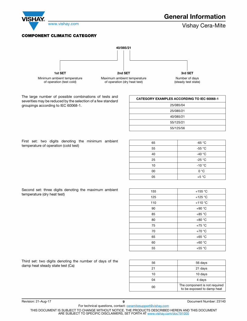
COMPONENT CLIMATIC CATEGORY
The large number of possible combinations of tests and severities may be reduced by the selection of a few standard groupings according to IEC 60068-1.
First set: two digits denoting the minimum ambient temperature of operation (cold test)
Second set: three digits denoting the maximum ambient temperature (dry heat test)
Third set: two digits denoting the number of days of the damp heat steady state test (Ca)
40/085/21
1st SET 2nd SET 3rd SET
Minimum ambient temperatureof operation (test cold)
Maximum ambient temperatureof operation (dry heat test)
Number of days(steady test state)
CATEGORY EXAMPLES ACCORDING TO IEC 60068-1
25/085/04
25/085/21
40/085/21
55/125/21
55/125/56
65 -65 °C
55 -55 °C
40 -40 °C
25 -25 °C
10 -10 °C
00 0 °C
05 +5 °C
155 +155 °C
125 +125 °C
110 +110 °C
90 +90 °C
85 +85 °C
80 +80 °C
75 +75 °C
70 +70 °C
65 +65 °C
60 +60 °C
55 +55 °C
56 56 days
21 21 days
10 10 days
04 4 days
00 The component is not required to be exposed to damp heat
General Informationwww.vishay.com Vishay Cera-Mite
Revision: 21-Aug-17 10 Document Number: 23140For technical questions, contact: [email protected]
THIS DOCUMENT IS SUBJECT TO CHANGE WITHOUT NOTICE. THE PRODUCTS DESCRIBED HEREIN AND THIS DOCUMENTARE SUBJECT TO SPECIFIC DISCLAIMERS, SET FORTH AT www.vishay.com/doc?91000
STORAGE
The capacitors must not be stored in a corrosive atmosphere, where sulphide or chloride gas, acid, alkali or salt are present. Exposure of the components to moisture, should be avoided. The solderability of the leads is not affected by storage of up to 24 months (temperature +10 °C to +40 °C, relative humidity up to 60 % RH). Class 2 ceramic dielectric capacitors are also subject to aging see previous page.
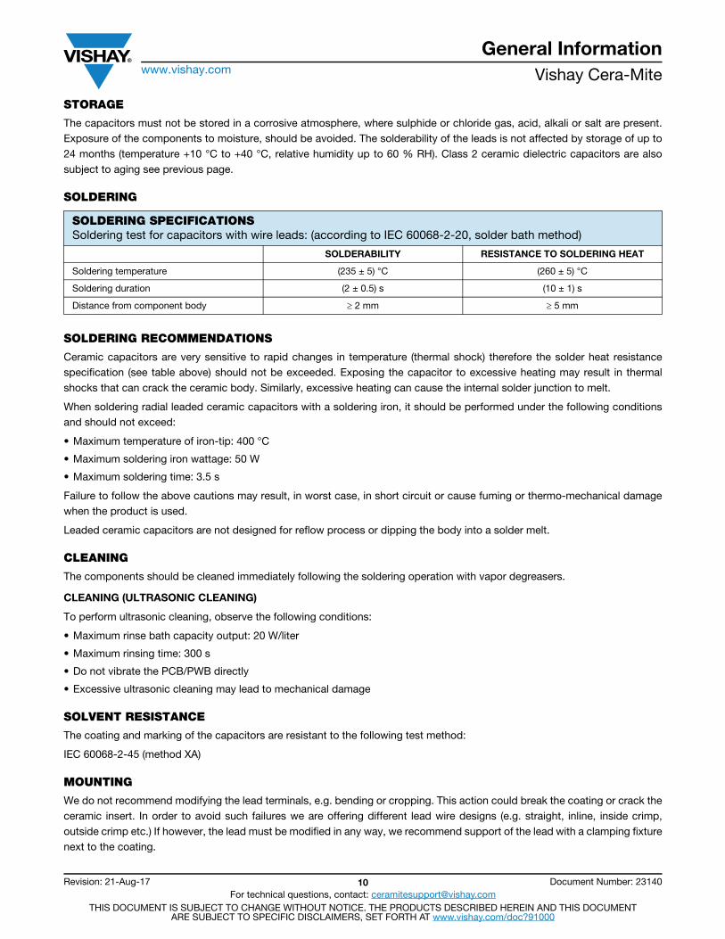
SOLDERING
SOLDERING RECOMMENDATIONS
Ceramic capacitors are very sensitive to rapid changes in temperature (thermal shock) therefore the solder heat resistance specification (see table above) should not be exceeded. Exposing the capacitor to excessive heating may result in thermal shocks that can crack the ceramic body. Similarly, excessive heating can cause the internal solder junction to melt.
When soldering radial leaded ceramic capacitors with a soldering iron, it should be performed under the following conditions and should not exceed:
• Maximum temperature of iron-tip: 400 °C
• Maximum soldering iron wattage: 50 W
• Maximum soldering time: 3.5 s
Failure to follow the above cautions may result, in worst case, in short circuit or cause fuming or thermo-mechanical damage when the product is used.
Leaded ceramic capacitors are not designed for reflow process or dipping the body into a solder melt.
CLEANING
The components should be cleaned immediately following the soldering operation with vapor degreasers.
CLEANING (ULTRASONIC CLEANING)
To perform ultrasonic cleaning, observe the following conditions:
• Maximum rinse bath capacity output: 20 W/liter
• Maximum rinsing time: 300 s
• Do not vibrate the PCB/PWB directly
• Excessive ultrasonic cleaning may lead to mechanical damage
SOLVENT RESISTANCE
The coating and marking of the capacitors are resistant to the following test method:
IEC 60068-2-45 (method XA)
MOUNTING
We do not recommend modifying the lead terminals, e.g. bending or cropping. This action could break the coating or crack the ceramic insert. In order to avoid such failures we are offering different lead wire designs (e.g. straight, inline, inside crimp, outside crimp etc.) If however, the lead must be modified in any way, we recommend support of the lead with a clamping fixture next to the coating.
SOLDERING SPECIFICATIONSSoldering test for capacitors with wire leads: (according to IEC 60068-2-20, solder bath method)
SOLDERABILITY RESISTANCE TO SOLDERING HEAT
Soldering temperature (235 ± 5) °C (260 ± 5) °C
Soldering duration (2 ± 0.5) s (10 ± 1) s
Distance from component body 2 mm 5 mm
General Informationwww.vishay.com Vishay Cera-Mite
Revision: 21-Aug-17 11 Document Number: 23140For technical questions, contact: [email protected]
THIS DOCUMENT IS SUBJECT TO CHANGE WITHOUT NOTICE. THE PRODUCTS DESCRIBED HEREIN AND THIS DOCUMENTARE SUBJECT TO SPECIFIC DISCLAIMERS, SET FORTH AT www.vishay.com/doc?91000
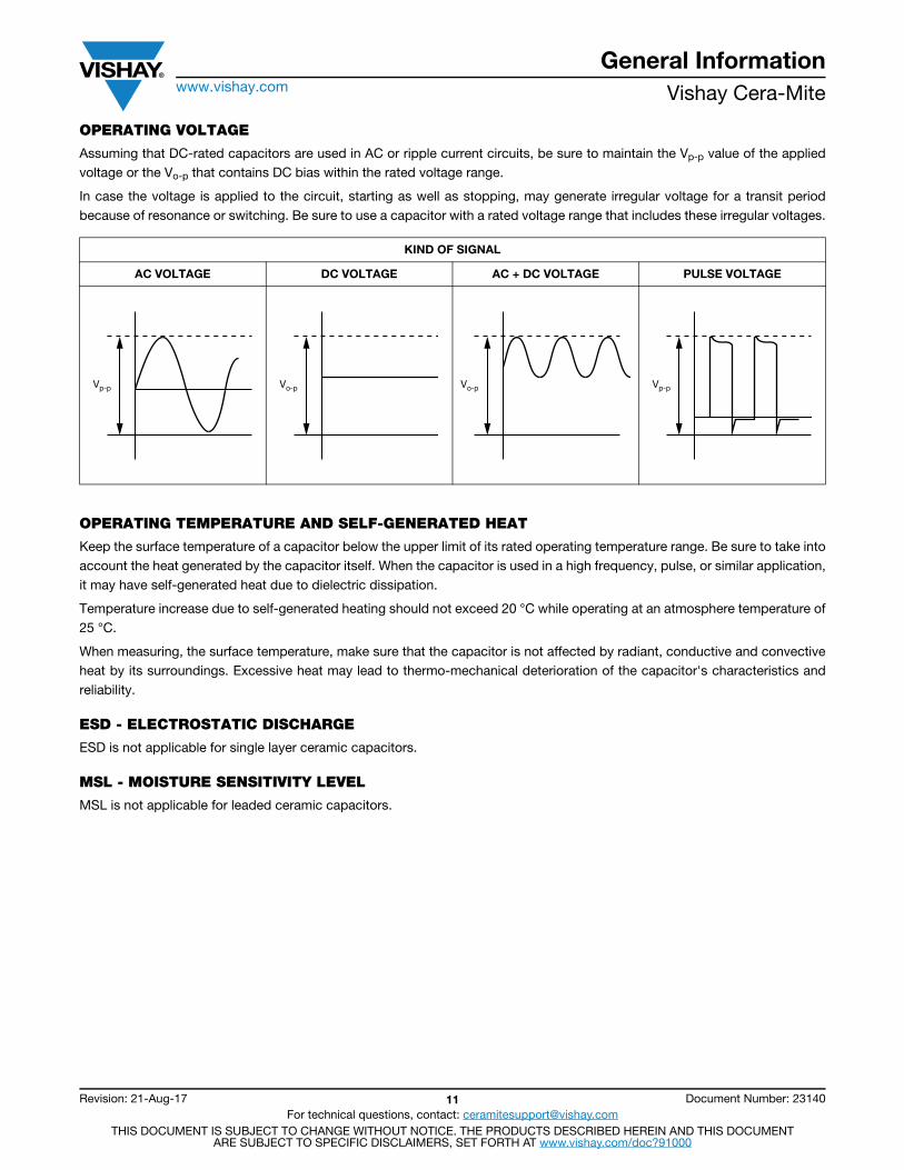
OPERATING VOLTAGE
Assuming that DC-rated capacitors are used in AC or ripple current circuits, be sure to maintain the Vp-p value of the applied voltage or the Vo-p that contains DC bias within the rated voltage range.
In case the voltage is applied to the circuit, starting as well as stopping, may generate irregular voltage for a transit period because of resonance or switching. Be sure to use a capacitor with a rated voltage range that includes these irregular voltages.
OPERATING TEMPERATURE AND SELF-GENERATED HEAT
Keep the surface temperature of a capacitor below the upper limit of its rated operating temperature range. Be sure to take into account the heat generated by the capacitor itself. When the capacitor is used in a high frequency, pulse, or similar application, it may have self-generated heat due to dielectric dissipation.
Temperature increase due to self-generated heating should not exceed 20 °C while operating at an atmosphere temperature of 25 °C.
When measuring, the surface temperature, make sure that the capacitor is not affected by radiant, conductive and convective heat by its surroundings. Excessive heat may lead to thermo-mechanical deterioration of the capacitor's characteristics and reliability.
ESD - ELECTROSTATIC DISCHARGE
ESD is not applicable for single layer ceramic capacitors.
MSL - MOISTURE SENSITIVITY LEVEL
MSL is not applicable for leaded ceramic capacitors.
KIND OF SIGNAL
AC VOLTAGE DC VOLTAGE AC + DC VOLTAGE PULSE VOLTAGE
Vp-p Vo-p Vo-p Vp-p
General Informationwww.vishay.com Vishay Cera-Mite
Revision: 21-Aug-17 12 Document Number: 23140For technical questions, contact: [email protected]
THIS DOCUMENT IS SUBJECT TO CHANGE WITHOUT NOTICE. THE PRODUCTS DESCRIBED HEREIN AND THIS DOCUMENTARE SUBJECT TO SPECIFIC DISCLAIMERS, SET FORTH AT www.vishay.com/doc?91000
AOQ - AVERAGE OUTGOING QUALITYIn the final control all lots (100 % lot-by-lot) are tested on sample base.
All possible defects are classified into minor and major defects.
They are defined as follows:
MAJOR DEFECTS
• Defects from which is to assume or known that they create dangerous situations for humans
• Defects which may create considerable property damage
• Defects from which is to expect that the pertain equipment will fail
• Defects which create essential reduction of the usability for the planned application
Lots with major defects always will be rejected.
It is essential: target = zero defect
MINOR DEFECTS
• Defects which do not create essential reduce the usability for the planned application
• Defects which affect the usability, function or assembly of the pertain equipment slightly
• Defects which increase substantial the internal (Vishay’s) rejects
Minor defects shall not exceed the acceptance of the required sampling plan otherwise the lot will be rejected.
The AOQ is calculated on a quarterly basis for mechanical and electrical defects.
All lots with major defects and all lots with more minor defects as accepted in the relevant sampling plan will be rejected. That will be set to the ratio with the number of tested parts.
Actual the AOQ is
AOQmechanical: < 50 ppm
AOQelectrical: < 150 ppm
These values are the End of Line Quality. The customer may expect lower AOQ levels.
RELIABILITYBecause of controlled manufacturing processes the quality of the ceramic capacitors is maintained on a high level.
The reliability data will be determined from the results of electrical endurance tests according the relevant national or international specification.
The endurance tests are performed on the upper category temperature and with applied load according the relevant specification. The applied voltage is up to 1.5 times of rated voltage. It depends on the specification.
As failure criterion is fixed:Short circuit during test, 2 times the required limits according the relevant specification.
Base for reliability calculation is the international specification IEC 61709.
The failure rate of our ceramic capacitors is
CD capacitors class 1 ceramic dielectric: 100 fit
CD capacitors class 2 ceramic dielectric: 500 fit
AC line rated capacitors: 5 fit
Detailed information is available on request.
General Informationwww.vishay.com Vishay Cera-Mite
Revision: 21-Aug-17 13 Document Number: 23140For technical questions, contact: [email protected]
THIS DOCUMENT IS SUBJECT TO CHANGE WITHOUT NOTICE. THE PRODUCTS DESCRIBED HEREIN AND THIS DOCUMENTARE SUBJECT TO SPECIFIC DISCLAIMERS, SET FORTH AT www.vishay.com/doc?91000
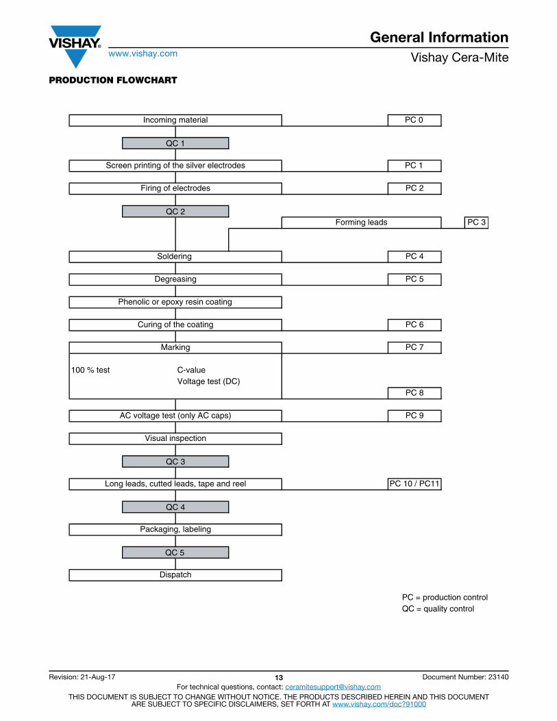
PRODUCTION FLOWCHART
PC 0
PC 1
PC 2
PC 3
PC 4
PC 5
PC 6
PC 7
C-valueVoltage test (DC)
PC 8
PC 9
PC 10 / PC11
PC = production controlQC = quality control
Incoming material
QC 1
Screen printing of the silver electrodes
Firing of electrodes
QC 2Forming leads
Soldering
Degreasing
Phenolic or epoxy resin coating
Curing of the coating
Marking
100 % test
AC voltage test (only AC caps)
Visual inspection
QC 3
Long leads, cutted leads, tape and reel
QC 4
Packaging, labeling
QC 5
Dispatch
General Informationwww.vishay.com Vishay Cera-Mite
Revision: 21-Aug-17 14 Document Number: 23140For technical questions, contact: [email protected]
THIS DOCUMENT IS SUBJECT TO CHANGE WITHOUT NOTICE. THE PRODUCTS DESCRIBED HEREIN AND THIS DOCUMENTARE SUBJECT TO SPECIFIC DISCLAIMERS, SET FORTH AT www.vishay.com/doc?91000
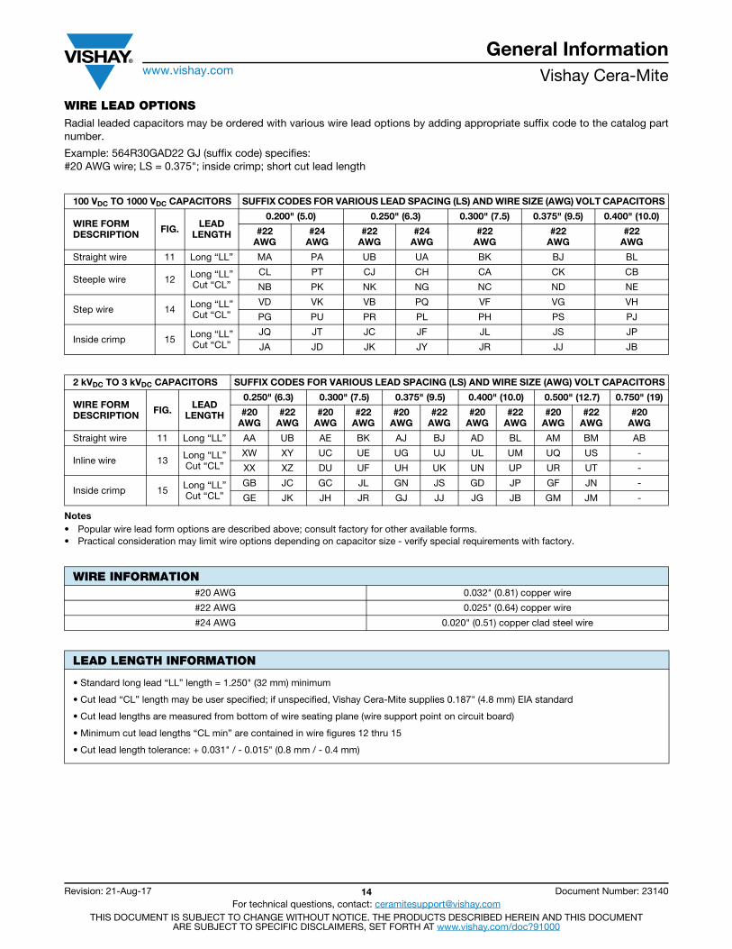
WIRE LEAD OPTIONSRadial leaded capacitors may be ordered with various wire lead options by adding appropriate suffix code to the catalog part number.
Example: 564R30GAD22 GJ (suffix code) specifies: #20 AWG wire; LS = 0.375"; inside crimp; short cut lead length
Notes• Popular wire lead form options are described above; consult factory for other available forms.• Practical consideration may limit wire options depending on capacitor size - verify special requirements with factory.
100 VDC TO 1000 VDC CAPACITORS SUFFIX CODES FOR VARIOUS LEAD SPACING (LS) AND WIRE SIZE (AWG) VOLT CAPACITORS
WIRE FORMDESCRIPTION FIG. LEAD
LENGTH
0.200" (5.0) 0.250" (6.3) 0.300" (7.5) 0.375" (9.5) 0.400" (10.0)
#22AWG
#24AWG
#22AWG
#24AWG
#22AWG
#22AWG
#22AWG
Straight wire 11 Long “LL” MA PA UB UA BK BJ BL
Steeple wire 12 Long “LL”Cut “CL”
CL PT CJ CH CA CK CB
NB PK NK NG NC ND NE
Step wire 14 Long “LL”Cut “CL”
VD VK VB PQ VF VG VH
PG PU PR PL PH PS PJ
Inside crimp 15 Long “LL”Cut “CL”
JQ JT JC JF JL JS JP
JA JD JK JY JR JJ JB
2 kVDC TO 3 kVDC CAPACITORS SUFFIX CODES FOR VARIOUS LEAD SPACING (LS) AND WIRE SIZE (AWG) VOLT CAPACITORS
WIRE FORMDESCRIPTION FIG. LEAD
LENGTH
0.250" (6.3) 0.300" (7.5) 0.375" (9.5) 0.400" (10.0) 0.500" (12.7) 0.750" (19)
#20AWG
#22AWG
#20AWG
#22AWG
#20AWG
#22AWG
#20AWG
#22AWG
#20AWG
#22AWG
#20AWG
Straight wire 11 Long “LL” AA UB AE BK AJ BJ AD BL AM BM AB
Inline wire 13 Long “LL”Cut “CL”
XW XY UC UE UG UJ UL UM UQ US -
XX XZ DU UF UH UK UN UP UR UT -
Inside crimp 15 Long “LL”Cut “CL”
GB JC GC JL GN JS GD JP GF JN -
GE JK JH JR GJ JJ JG JB GM JM -
WIRE INFORMATION#20 AWG 0.032" (0.81) copper wire
#22 AWG 0.025" (0.64) copper wire
#24 AWG 0.020" (0.51) copper clad steel wire
LEAD LENGTH INFORMATION
• Standard long lead “LL” length = 1.250" (32 mm) minimum
• Cut lead “CL” length may be user specified; if unspecified, Vishay Cera-Mite supplies 0.187" (4.8 mm) EIA standard
• Cut lead lengths are measured from bottom of wire seating plane (wire support point on circuit board)
• Minimum cut lead lengths “CL min” are contained in wire figures 12 thru 15
• Cut lead length tolerance: + 0.031" / - 0.015" (0.8 mm / - 0.4 mm)
General Informationwww.vishay.com Vishay Cera-Mite
Revision: 21-Aug-17 15 Document Number: 23140For technical questions, contact: [email protected]
THIS DOCUMENT IS SUBJECT TO CHANGE WITHOUT NOTICE. THE PRODUCTS DESCRIBED HEREIN AND THIS DOCUMENTARE SUBJECT TO SPECIFIC DISCLAIMERS, SET FORTH AT www.vishay.com/doc?91000
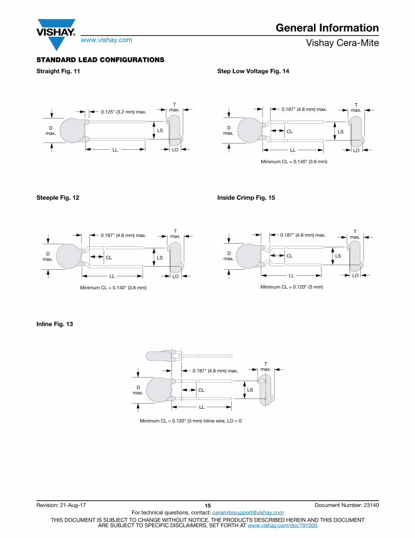
STANDARD LEAD CONFIGURATIONS
Straight Fig. 11
Steeple Fig. 12
Step Low Voltage Fig. 14
Inside Crimp Fig. 15
Inline Fig. 13
0.125" (3.2 mm) max.
LS
Tmax.
Dmax.
LOLL
0.187" (4.8 mm) max.
CL
Minimum CL = 0.140" (3.6 mm)
LS
LOLL
Tmax.
Dmax.
0.187" (4.8 mm) max.
CL
Minimum CL = 0.140" (3.6 mm)
LS
LOLL
Tmax.
Dmax.
0.187" (4.8 mm) max.
LS
LO
CL
Minimum CL = 0.120" (3 mm)
max.T
max.D
LL
0.187" (4.8 mm) max.
LS
Tmax.
Dmax. CL
Minimum CL = 0.120" (3 mm) inline wire, LO = 0
LL
General Informationwww.vishay.com Vishay Cera-Mite
Revision: 21-Aug-17 16 Document Number: 23140For technical questions, contact: [email protected]
THIS DOCUMENT IS SUBJECT TO CHANGE WITHOUT NOTICE. THE PRODUCTS DESCRIBED HEREIN AND THIS DOCUMENTARE SUBJECT TO SPECIFIC DISCLAIMERS, SET FORTH AT www.vishay.com/doc?91000
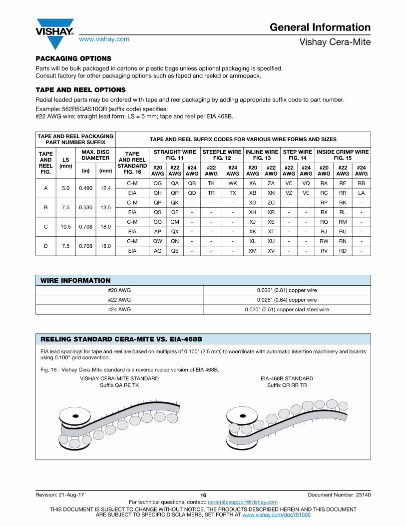
PACKAGING OPTIONSParts will be bulk packaged in cartons or plastic bags unless optional packaging is specified.Consult factory for other packaging options such as taped and reeled or ammopack.
TAPE AND REEL OPTIONSRadial leaded parts may be ordered with tape and reel packaging by adding appropriate suffix code to part number.
Example: 562R5GAS10QR (suffix code) specifies:#22 AWG wire; straight lead form; LS = 5 mm; tape and reel per EIA 468B.
TAPE AND REEL PACKAGINGPART NUMBER SUFFIX TAPE AND REEL SUFFIX CODES FOR VARIOUS WIRE FORMS AND SIZES
TAPEANDREELFIG.
LS(mm)
MAX. DISCDIAMETER
TAPEAND REELSTANDARD
FIG. 16
STRAIGHT WIREFIG. 11
STEEPLE WIREFIG. 12
INLINE WIREFIG. 13
STEP WIREFIG. 14
INSIDE CRIMP WIREFIG. 15
(in) (mm) #20AWG
#22AWG
#24AWG
#22AWG
#24AWG
#20AWG
#22AWG
#22AWG
#24AWG
#20AWG
#22AWG
#24AWG
A 5.0 0.490 12.4C-M QG QA QB TK WK XA ZA VC VQ RA RE RB
EIA QH QR QD TR TX XB XN VZ VE RC RR LA
B 7.5 0.530 13.5C-M QP QK - - - XG ZC - - RP RK -
EIA QS QF - - - XH XR - - RX RL -
C 10.5 0.708 18.0C-M QQ QM - - - XJ XS - - RQ RM -
EIA AP QX - - - XK XT - - RJ RU -
D 7.5 0.708 18.0C-M QW QN - - - XL XU - - RW RN -
EIA AQ QE - - - XM XV - - RV RD -
WIRE INFORMATION#20 AWG 0.032" (0.81) copper wire
#22 AWG 0.025" (0.64) copper wire
#24 AWG 0.020" (0.51) copper clad steel wire
REELING STANDARD CERA-MITE VS. EIA-468B
EIA lead spacings for tape and reel are based on multiples of 0.100" (2.5 mm) to coordinate with automatic insertion machinery and boards using 0.100" grid convention.
Fig. 16 - Vishay Cera-Mite standard is a reverse reeled version of EIA 468B.
VISHAY CERA-MITE STANDARDSuffix QA RE TK
EIA-468B STANDARDSuffix QR RR TR
General Informationwww.vishay.com Vishay Cera-Mite
Revision: 21-Aug-17 17 Document Number: 23140For technical questions, contact: [email protected]
THIS DOCUMENT IS SUBJECT TO CHANGE WITHOUT NOTICE. THE PRODUCTS DESCRIBED HEREIN AND THIS DOCUMENTARE SUBJECT TO SPECIFIC DISCLAIMERS, SET FORTH AT www.vishay.com/doc?91000
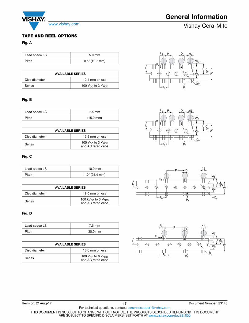
TAPE AND REEL OPTIONS
Fig. A
Fig. B
Fig. C
Fig. D
Lead space LS 5.0 mm
Pitch 0.5" (12.7 mm)
AVAILABLE SERIES
Disc diameter 12.4 mm or less
Series 100 VDC to 3 kVDC
L
P2
P1
P D S
WW0
W2
H W1
D 0P3P0
FF
Δ
Lead space LS 7.5 mm
Pitch (15.0 mm)
AVAILABLE SERIES
Disc diameter 13.5 mm or less
Series 100 VDC to 3 kVDCand AC rated caps
L
P2
P1
P D S
WW0
W2
H W1
D0
P3P0
FF
Δ
Lead space LS 10.0 mm
Pitch 1.0" (25.4 mm)
AVAILABLE SERIES
Disc diameter 18.0 mm or less
Series 100 kVDC to 6 kVDCand AC rated caps
F
L
P0
P1
P3
DPSΔ
D0
2
W0
W1H
W
W
Lead space LS 7.5 mm
Pitch 30.0 mm
AVAILABLE SERIES
Disc diameter 18.0 mm or less
Series 100 VDC to 6 kVDCand AC rated caps
F
D
P1
P0
P2
2
P3
P
L
S
D0
WW0
W1H
W
Δ
General Informationwww.vishay.com Vishay Cera-Mite
Revision: 21-Aug-17 18 Document Number: 23140For technical questions, contact: [email protected]
THIS DOCUMENT IS SUBJECT TO CHANGE WITHOUT NOTICE. THE PRODUCTS DESCRIBED HEREIN AND THIS DOCUMENTARE SUBJECT TO SPECIFIC DISCLAIMERS, SET FORTH AT www.vishay.com/doc?91000
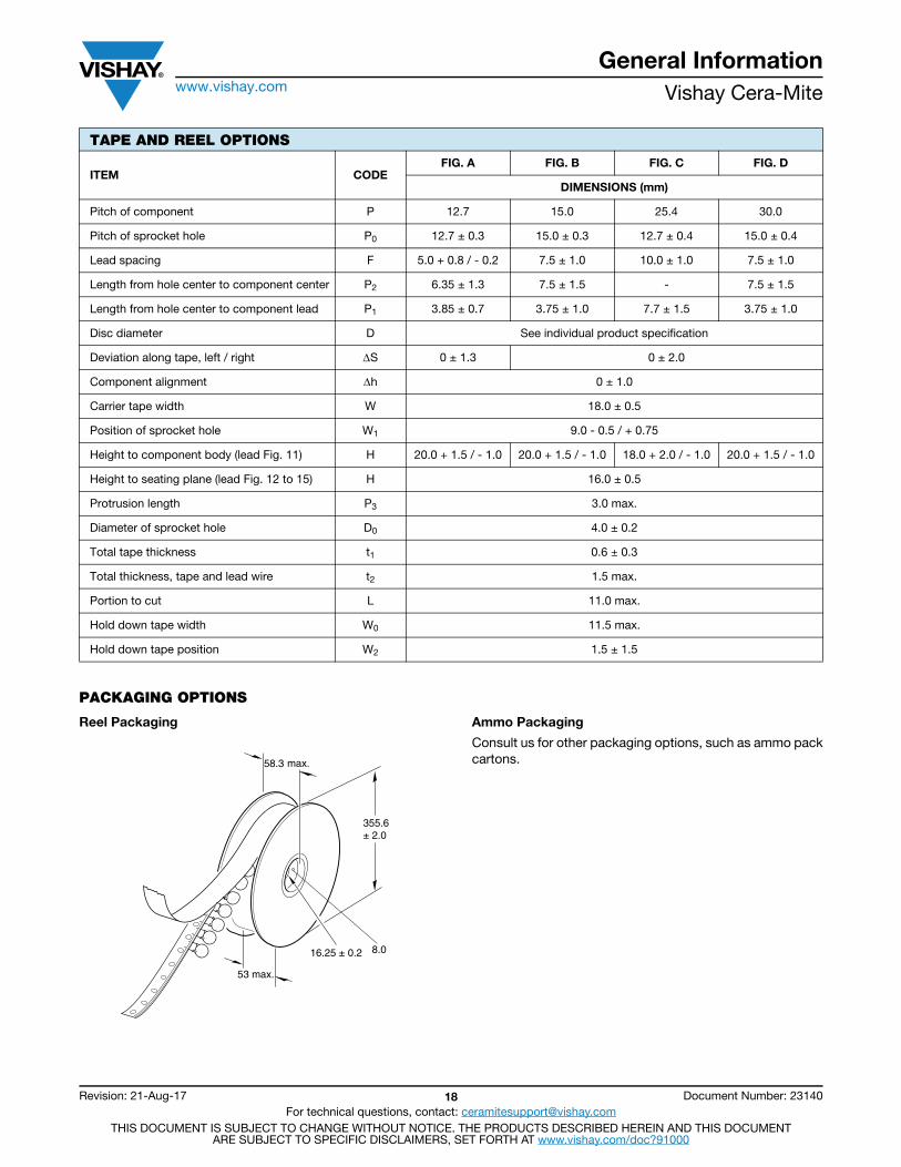
PACKAGING OPTIONS
Reel Packaging Ammo Packaging
Consult us for other packaging options, such as ammo pack cartons.
TAPE AND REEL OPTIONS
ITEM CODEFIG. A FIG. B FIG. C FIG. D
DIMENSIONS (mm)
Pitch of component P 12.7 15.0 25.4 30.0
Pitch of sprocket hole P0 12.7 ± 0.3 15.0 ± 0.3 12.7 ± 0.4 15.0 ± 0.4
Lead spacing F 5.0 + 0.8 / - 0.2 7.5 ± 1.0 10.0 ± 1.0 7.5 ± 1.0
Length from hole center to component center P2 6.35 ± 1.3 7.5 ± 1.5 - 7.5 ± 1.5
Length from hole center to component lead P1 3.85 ± 0.7 3.75 ± 1.0 7.7 ± 1.5 3.75 ± 1.0
Disc diameter D See individual product specification
Deviation along tape, left / right S 0 ± 1.3 0 ± 2.0
Component alignment h 0 ± 1.0
Carrier tape width W 18.0 ± 0.5
Position of sprocket hole W1 9.0 - 0.5 / + 0.75
Height to component body (lead Fig. 11) H 20.0 + 1.5 / - 1.0 20.0 + 1.5 / - 1.0 18.0 + 2.0 / - 1.0 20.0 + 1.5 / - 1.0
Height to seating plane (lead Fig. 12 to 15) H 16.0 ± 0.5
Protrusion length P3 3.0 max.
Diameter of sprocket hole D0 4.0 ± 0.2
Total tape thickness t1 0.6 ± 0.3
Total thickness, tape and lead wire t2 1.5 max.
Portion to cut L 11.0 max.
Hold down tape width W0 11.5 max.
Hold down tape position W2 1.5 ± 1.5
58.3 max.
355.6± 2.0
16.25 ± 0.2 8.0
53 max.
General Informationwww.vishay.com Vishay Cera-Mite
Revision: 21-Aug-17 19 Document Number: 23140For technical questions, contact: [email protected]
THIS DOCUMENT IS SUBJECT TO CHANGE WITHOUT NOTICE. THE PRODUCTS DESCRIBED HEREIN AND THIS DOCUMENTARE SUBJECT TO SPECIFIC DISCLAIMERS, SET FORTH AT www.vishay.com/doc?91000
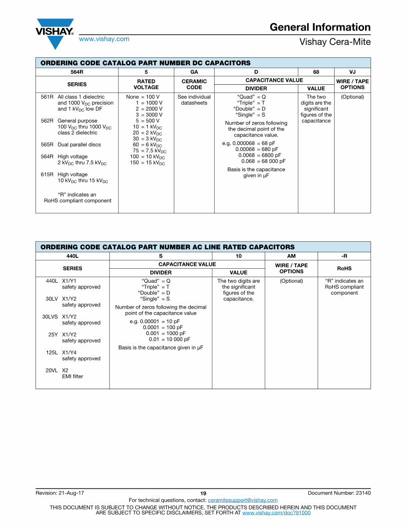
ORDERING CODE CATALOG PART NUMBER DC CAPACITORS564R 5 GA D 68 VJ
SERIES RATEDVOLTAGE
CERAMICCODE
CAPACITANCE VALUE WIRE / TAPEOPTIONSDIVIDER VALUE
561R
562R
565R
564R
615R
All class 1 dielectricand 1000 VDC precisionand 1 kVDC low DFGeneral purpose100 VDC thru 1000 VDCclass 2 dielectricDual parallel discsHigh voltage2 kVDC thru 7.5 kVDCHigh voltage10 kVDC thru 15 kVDC
None 1 2 3 5
10 20 30 60 75
100 150
= 100 V= 1000 V= 2000 V= 3000 V= 500 V= 1 kVDC= 2 kVDC= 3 kVDC= 6 kVDC= 7.5 kVDC= 10 kVDC= 15 kVDC
See individualdatasheets
“Quad” “Triple”
“Double” “Single”
= Q= T= D= S
The two digits are the
significantfigures of thecapacitance
(Optional)
Number of zeros followingthe decimal point of the
capacitance value.
e.g. 0.000068 0.00068
0.0068 0.068
= 68 pF= 680 pF= 6800 pF= 68 000 pF
Basis is the capacitancegiven in μF
“R” indicates an RoHS compliant component
ORDERING CODE CATALOG PART NUMBER AC LINE RATED CAPACITORS440L S 10 AM -R
SERIESCAPACITANCE VALUE WIRE / TAPE
OPTIONS RoHSDIVIDER VALUE
440L
30LV
30LVS
25Y
125L
20VL
X1/Y1safety approvedX1/Y2safety approvedX1/Y2safety approvedX1/Y2safety approvedX1/Y4safety approvedX2EMI filter
“Quad” “Triple”
“Double” “Single”
= Q= T= D= S
The two digits are the significantfigures of thecapacitance.
(Optional) “R” indicates anRoHS compliant
component
Number of zeros following the decimal point of the capacitance value
e.g. 0.00001 0.0001
0.001 0.01
= 10 pF= 100 pF= 1000 pF= 10 000 pF
Basis is the capacitance given in μF
General Informationwww.vishay.com Vishay Cera-Mite
Revision: 21-Aug-17 20 Document Number: 23140For technical questions, contact: [email protected]
THIS DOCUMENT IS SUBJECT TO CHANGE WITHOUT NOTICE. THE PRODUCTS DESCRIBED HEREIN AND THIS DOCUMENTARE SUBJECT TO SPECIFIC DISCLAIMERS, SET FORTH AT www.vishay.com/doc?91000
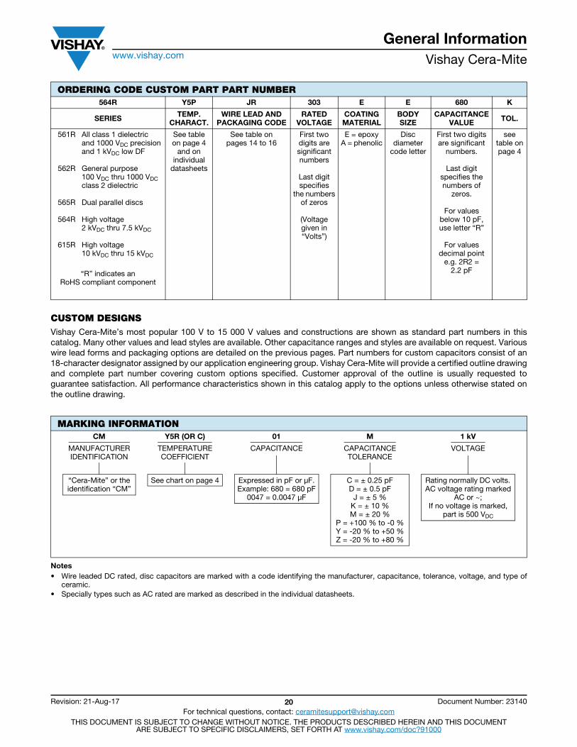
CUSTOM DESIGNSVishay Cera-Mite’s most popular 100 V to 15 000 V values and constructions are shown as standard part numbers in this catalog. Many other values and lead styles are available. Other capacitance ranges and styles are available on request. Various wire lead forms and packaging options are detailed on the previous pages. Part numbers for custom capacitors consist of an 18-character designator assigned by our application engineering group. Vishay Cera-Mite will provide a certified outline drawing and complete part number covering custom options specified. Customer approval of the outline is usually requested to guarantee satisfaction. All performance characteristics shown in this catalog apply to the options unless otherwise stated on the outline drawing.
Notes• Wire leaded DC rated, disc capacitors are marked with a code identifying the manufacturer, capacitance, tolerance, voltage, and type of
ceramic.• Specially types such as AC rated are marked as described in the individual datasheets.
ORDERING CODE CUSTOM PART PART NUMBER564R Y5P JR 303 E E 680 K
SERIES TEMP.CHARACT.
WIRE LEAD ANDPACKAGING CODE
RATED VOLTAGE
COATING MATERIAL
BODY SIZE
CAPACITANCEVALUE TOL.
561R
562R
565R
564R
615R
All class 1 dielectricand 1000 VDC precisionand 1 kVDC low DFGeneral purpose100 VDC thru 1000 VDCclass 2 dielectricDual parallel discsHigh voltage2 kVDC thru 7.5 kVDCHigh voltage10 kVDC thru 15 kVDC
See tableon page 4
and onindividual
datasheets
See table onpages 14 to 16
First two digits are significantnumbers
Last digitspecifies
the numbersof zeros
(Voltagegiven in “Volts”)
E = epoxyA = phenolic
Discdiameter
code letter
First two digits are significant
numbers.
Last digit specifies the numbers of
zeros.
For valuesbelow 10 pF,use letter “R”
For valuesdecimal point
e.g. 2R2 =2.2 pF
see table onpage 4
“R” indicates anRoHS compliant component
MARKING INFORMATIONCM Y5R (OR C) 01 M 1 kV
MANUFACTURERIDENTIFICATION
TEMPERATURECOEFFICIENT
CAPACITANCE CAPACITANCETOLERANCE
VOLTAGE
“Cera-Mite” or theidentification “CM”
See chart on page 4 Expressed in pF or μF.Example: 680 = 680 pF
0047 = 0.0047 μF
C = ± 0.25 pFD = ± 0.5 pF
J = ± 5 %K = ± 10 %M = ± 20 %
P = +100 % to -0 %Y = -20 % to +50 %Z = -20 % to +80 %
Rating normally DC volts. AC voltage rating marked
AC or ~; If no voltage is marked,
part is 500 VDC