Embed Size (px)
Citation preview

Centre for Electromagnetic and Antenna Engineering, Department of Electronic Engineering No 1
Achieving high gain and large bandwidth using hybrid DR antennas
to feed short horns
Nasimuddin1 and Karu Esselle2
1Institute for Infocomm Research, Singapore2Centre for Electromagnetic and Antenna Engineering
Department of Electronic Engineering, Macquarie University Sydney, NSW 2109, Australia
Email: [email protected], [email protected]
Centre for Electromagnetic and Antenna Engineering, Department of Electronic Engineering No 2
Outline
Introduction Gain-Enhancement using Surface Mounted Short Horns (SMSH) DRAs with SMSHs, designed for high gain Hybrid dilectric resonator on patch (DRoP) antennas with SMSHs, designed for high gain over wide bandwidth Conclusion
Centre for Electromagnetic and Antenna Engineering, Department of Electronic Engineering No 3
Introduction
• DRA has the advantages of low cost, compactness, high efficiency and a low profile.
• Traditional microstrip antennas and dielectric resonator antennas have gains around 6 dBi to 8 dBi.
Centre for Electromagnetic and Antenna Engineering, Department of Electronic Engineering No 4
To enhance the gain of DRAs, several methods have been employed:
offset dual-disk dielectric resonators (DR)
stacking parasitic DR with an air gap between radiating and parasitic DRs
Use of composite layered high permittivity DR
dielectric resonator loaded waveguide antenna with parasitic dielectric directors.
In most cases the gain enhancement is limited or the structure is complex. We propose to integrate DRAs and hybrid antennas with surface mount short horns to enhance gain significantly.
Centre for Electromagnetic and Antenna Engineering, Department of Electronic Engineering No 5
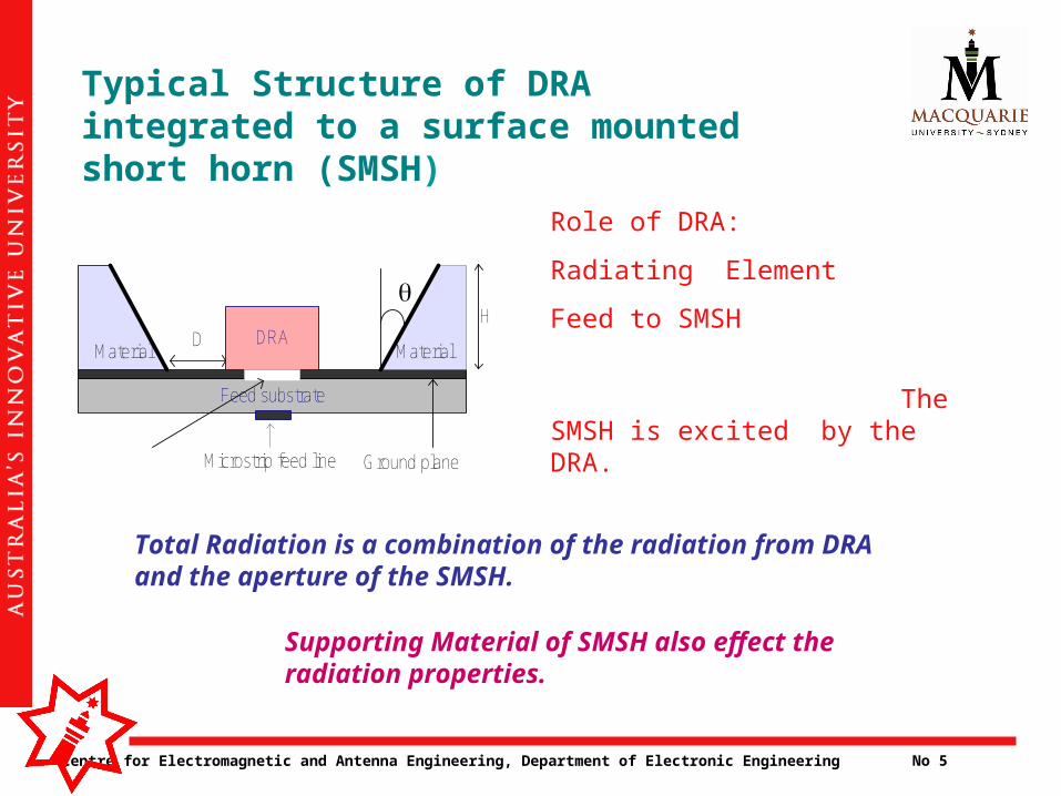
Typical Structure of DRA integrated to a surface mounted short horn (SMSH)
Feed substrate
DRAMaterial
Material
H
Microstrip feed line Ground plane
D
Role of DRA:
Radiating Element
Feed to SMSH
The SMSH is excited by the DRA.
Total Radiation is a combination of the radiation from DRA and the aperture of the SMSH.
Supporting Material of SMSH also effect the radiation properties.
Centre for Electromagnetic and Antenna Engineering, Department of Electronic Engineering No 6
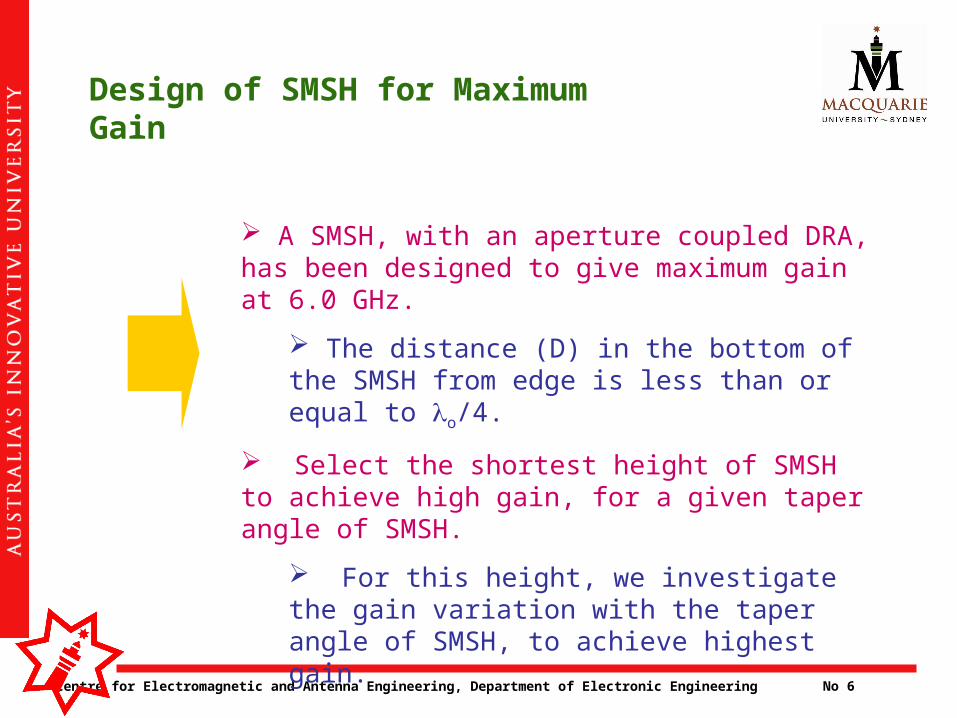
Design of SMSH for Maximum Gain
A SMSH, with an aperture coupled DRA, has been designed to give maximum gain at 6.0 GHz.
The distance (D) in the bottom of the SMSH from edge is less than or equal to o/4.
Select the shortest height of SMSH to achieve high gain, for a given taper angle of SMSH.
For this height, we investigate the gain variation with the taper angle of SMSH, to achieve highest gain.
Centre for Electromagnetic and Antenna Engineering, Department of Electronic Engineering No 7
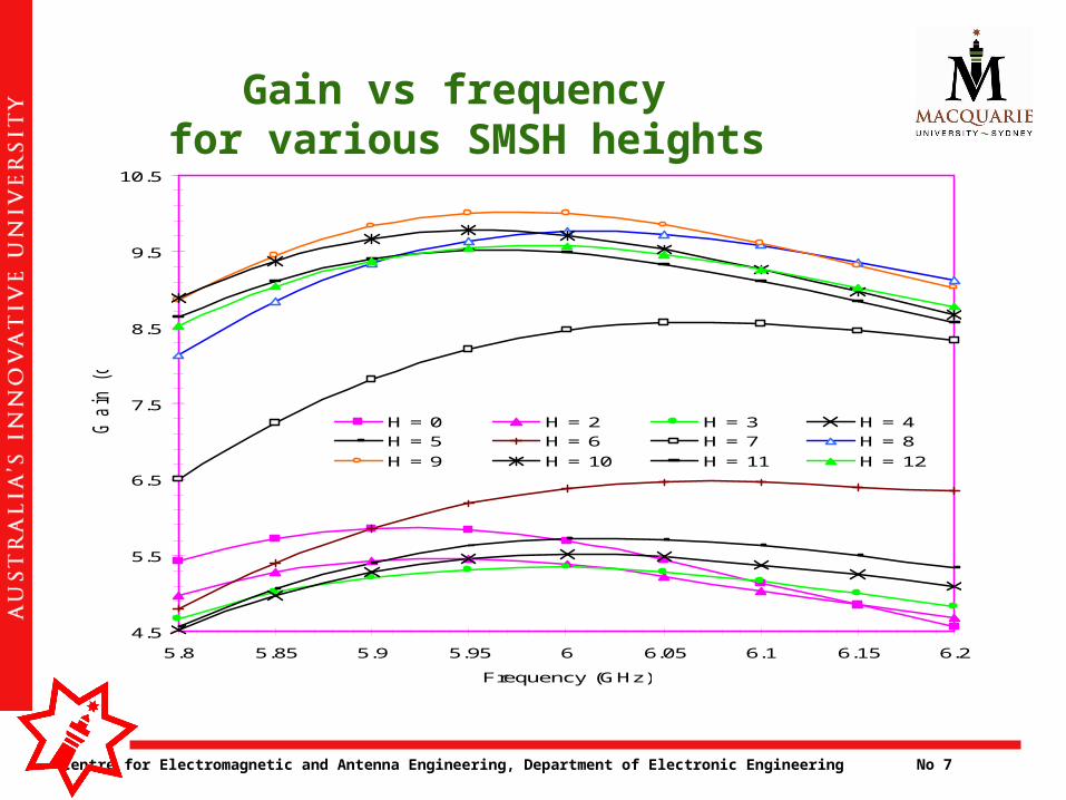
Gain vs frequency for various SMSH heights
4.5
5.5
6.5
7.5
8.5
9.5
10.5
5.8 5.85 5.9 5.95 6 6.05 6.1 6.15 6.2
Frequency (GHz)
Gain
(dB
i)
H = 0 H = 2 H = 3 H = 4H = 5 H = 6 H = 7 H = 8
H = 9 H = 10 H = 11 H = 12
Centre for Electromagnetic and Antenna Engineering, Department of Electronic Engineering No 8
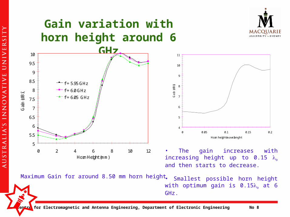
Gain variation with horn height around 6 GHz
5
5.5
6
6.5
7
7.5
8
8.5
9
9.5
10
0 2 4 6 8 10 12Horn Height (mm)
Gai
n (d
Bi)
f = 5.95 GHz
f = 6.0 GHz
f = 6.05 GHz
Maximum Gain for around 8.50 mm horn height
4
5
6
7
8
9
10
11
0 0.05 0.1 0.15 0.2
Horn height/wavelenght
Gai
n (d
Bi)
• The gain increases with increasing height up to 0.15 o and then starts to decrease.
• Smallest possible horn height with optimum gain is 0.15o at 6 GHz.
Centre for Electromagnetic and Antenna Engineering, Department of Electronic Engineering No 9
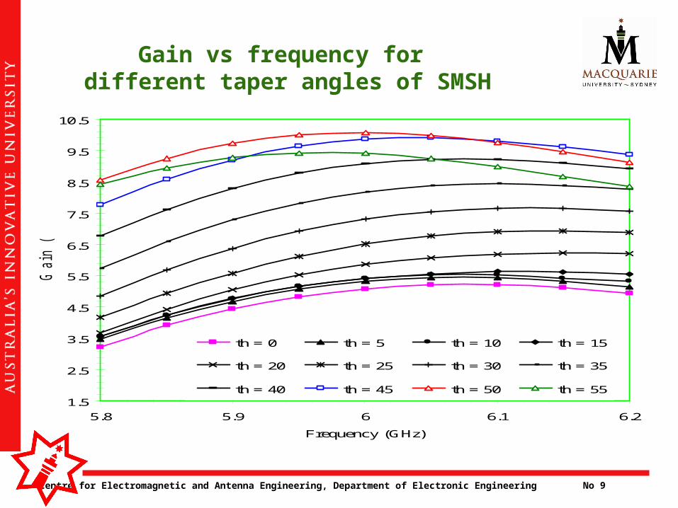
Gain vs frequency for different taper angles of SMSH
1.5
2.5
3.5
4.5
5.5
6.5
7.5
8.5
9.5
10.5
5.8 5.9 6 6.1 6.2
Frequency (GHz)
Gain
(dB
i)
th = 0 th = 5 th = 10 th = 15
th = 20 th = 25 th = 30 th = 35
th = 40 th = 45 th = 50 th = 55
Centre for Electromagnetic and Antenna Engineering, Department of Electronic Engineering No 10
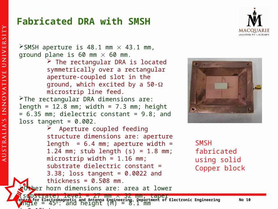
Fabricated DRA with SMSH
SMSH aperture is 48.1 mm 43.1 mm, ground plane is 60 mm 60 mm.
The rectangular DRA is located symmetrically over a rectangular aperture-coupled slot in the ground, which excited by a 50- microstrip line feed.
The rectangular DRA dimensions are: length = 12.8 mm; width = 7.3 mm; height = 6.35 mm; dielectric constant = 9.8; and loss tangent = 0.002.
Aperture coupled feeding structure dimensions are: aperture length = 6.4 mm; aperture width = 1.24 mm; stub length (s) = 1.8 mm; microstrip width = 1.16 mm; substrate dielectric constant = 3.38; loss tangent = 0.0022 and thickness = 0.508 mm.
Other horn dimensions are: area at lower (substrate) level = 27 mm 32 mm; taper angle = 45o: and height (H) = 8.1 mm (0.15o).
The total height of structure is only 0.172 o i.e. 8.61 mm at 6.0 GHz.
SMSH fabricated using solid Copper block
Centre for Electromagnetic and Antenna Engineering, Department of Electronic Engineering No 11
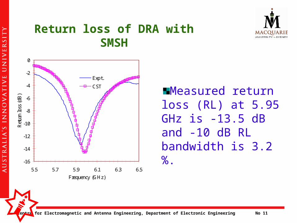
Return loss of DRA with SMSH
-16
-14
-12
-10
-8
-6
-4
-2
0
5.5 5.7 5.9 6.1 6.3 6.5
Frequency (GHz)
Ret
urn
loss
(dB
)
Expt.
CST
Measured return loss (RL) at 5.95 GHz is -13.5 dB and -10 dB RL bandwidth is 3.2 %.
Centre for Electromagnetic and Antenna Engineering, Department of Electronic Engineering No 12
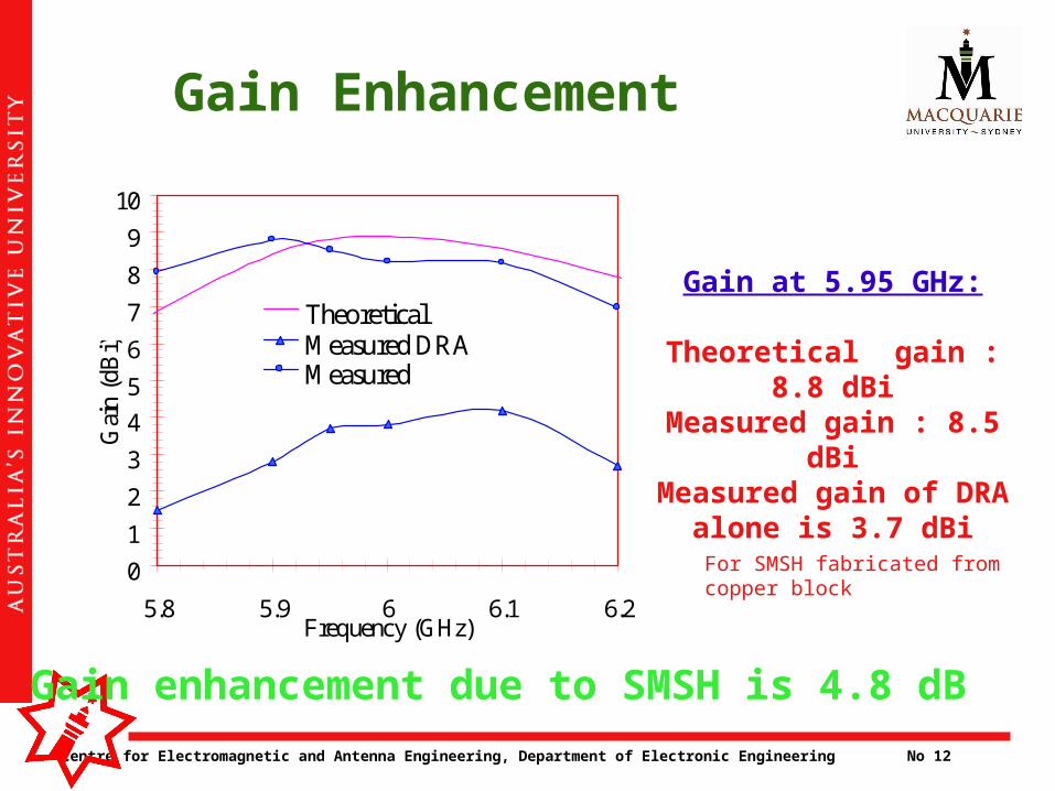
Gain Enhancement
0
1
2
3
4
5
6
7
8
9
10
5.8 5.9 6 6.1 6.2Frequency (GHz)
Gai
n (d
Bi)
TheoreticalMeasured DRA Measured
Gain at 5.95 GHz:
Theoretical gain : 8.8 dBiMeasured gain : 8.5 dBiMeasured gain of DRA
alone is 3.7 dBi
For SMSH fabricated from copper block
Gain enhancement due to SMSH is 4.8 dB
Centre for Electromagnetic and Antenna Engineering, Department of Electronic Engineering No 13
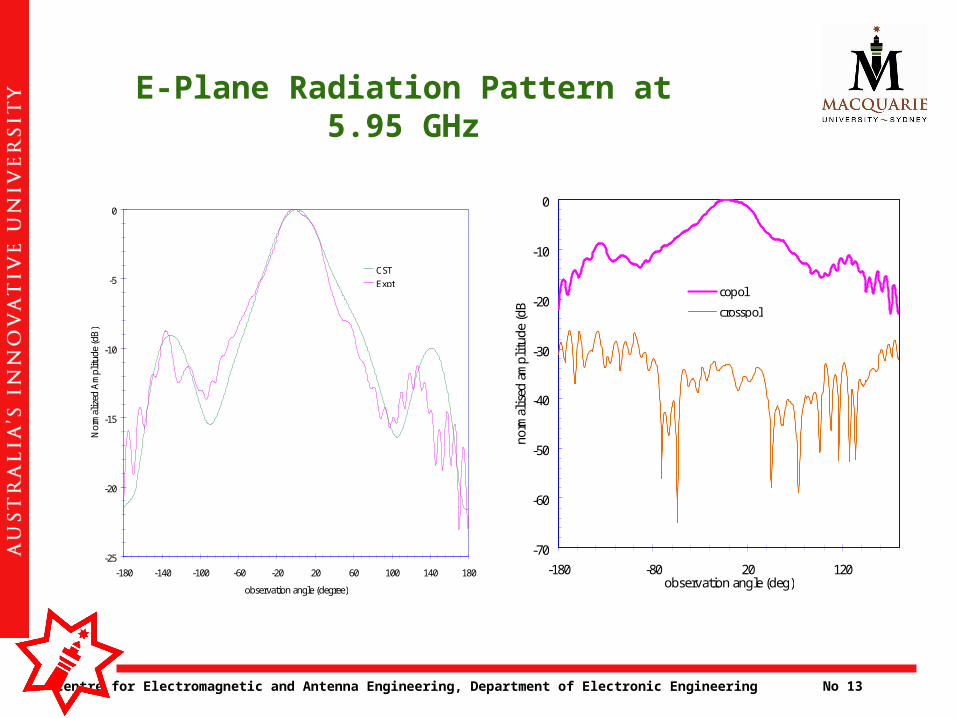
E-Plane Radiation Pattern at 5.95 GHz
-25
-20
-15
-10
-5
0
-180 -140 -100 -60 -20 20 60 100 140 180
observation angle (degree)
Nor
mal
ized
Am
plit
ude
(dB
)
CST
Expt
-70
-60
-50
-40
-30
-20
-10
0
-180 -80 20 120observation angle (deg)
norm
alis
ed a
mpl
itud
e (d
B)
copol
crosspol
Centre for Electromagnetic and Antenna Engineering, Department of Electronic Engineering No 14
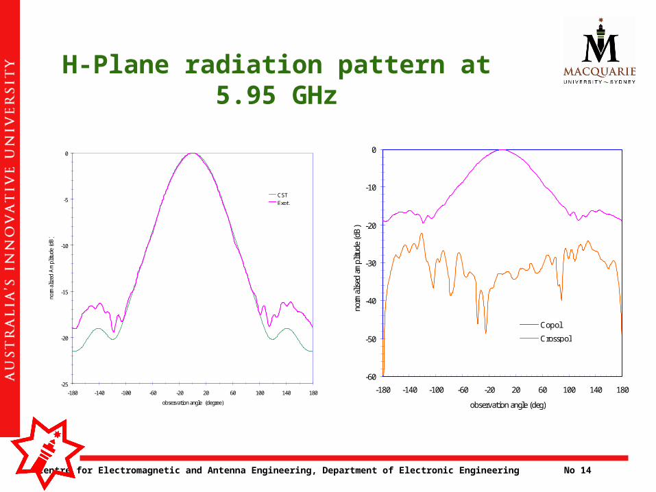
H-Plane radiation pattern at 5.95 GHz
-25
-20
-15
-10
-5
0
-180 -140 -100 -60 -20 20 60 100 140 180
observation angle (degree)
norm
aliz
ed A
mpl
itude
(dB
)
CST
Expt.
-60
-50
-40
-30
-20
-10
0
-180 -140 -100 -60 -20 20 60 100 140 180
observation angle (deg)
norm
alis
ed a
mpl
itude
(dB
)
Copol
Crosspol
Centre for Electromagnetic and Antenna Engineering, Department of Electronic Engineering No 15
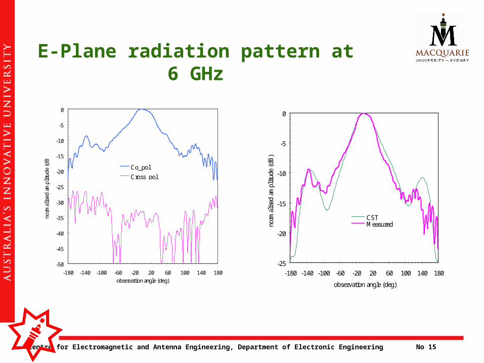
E-Plane radiation pattern at 6 GHz
-25
-20
-15
-10
-5
0
-180 -140 -100 -60 -20 20 60 100 140 180
observation angle (deg)
norm
alis
ed a
mpl
itud
e (d
B)
.
CSTMeasured
-50
-45
-40
-35
-30
-25
-20
-15
-10
-5
0
-180 -140 -100 -60 -20 20 60 100 140 180
observation angle (deg)
norm
alis
ed a
mpl
itud
e (d
B)
Co_pol
Cross_pol
Centre for Electromagnetic and Antenna Engineering, Department of Electronic Engineering No 16
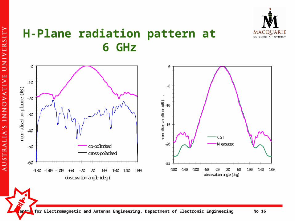
H-Plane radiation pattern at 6 GHz
-25
-20
-15
-10
-5
0
-180 -140 -100 -60 -20 20 60 100 140 180observation angle (deg)
norm
alis
ed a
mpl
itude
(dB
)
.
CST
Measured
-60
-50
-40
-30
-20
-10
0
-180 -140 -100 -60 -20 20 60 100 140 180
observation angle (deg)
norm
alis
ed a
mpl
itude
(dB
) .
co-polarised
cross-polarised
Centre for Electromagnetic and Antenna Engineering, Department of Electronic Engineering No 17
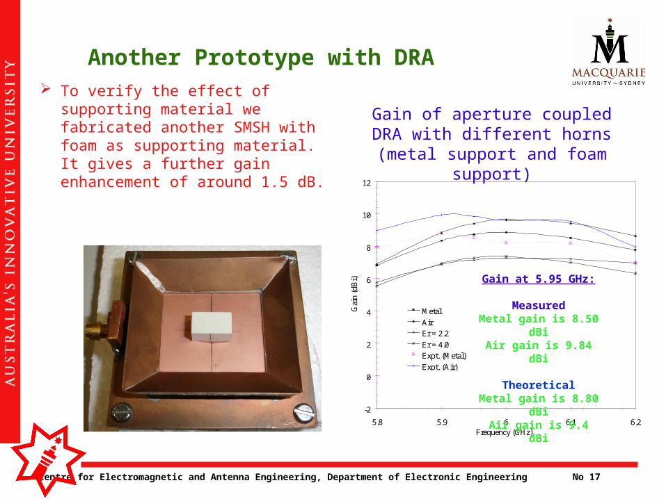
Another Prototype with DRA To verify the effect of
supporting material we fabricated another SMSH with foam as supporting material. It gives a further gain enhancement of around 1.5 dB.
-2
0
2
4
6
8
10
12
5.8 5.9 6 6.1 6.2Frequency (GHz)
Gai
n (d
Bi)
Metal
AirEr = 2.2
Er = 4.0Expt. (Metal)
Expt. (Air)
Gain of aperture coupled DRA with different horns (metal support and foam support)
Gain at 5.95 GHz:
MeasuredMetal gain is 8.50 dBi
Air gain is 9.84 dBi
TheoreticalMetal gain is 8.80 dBi
Air gain is 9.4 dBi
Centre for Electromagnetic and Antenna Engineering, Department of Electronic Engineering No 18
Feed substrate
DRA
Material
Material
Horn
Microstrip feedline Ground plane
Patch Substrate
Upper slot
Patch Resonator
H
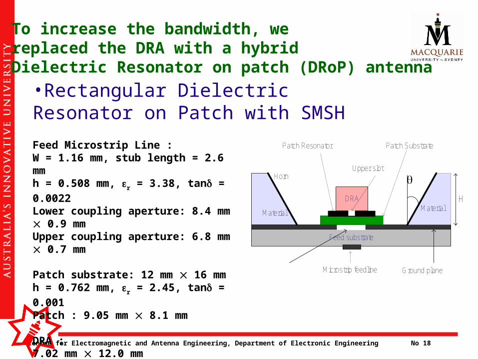
•Rectangular Dielectric Resonator on Patch with SMSH
Feed Microstrip Line :W = 1.16 mm, stub length = 2.6 mmh = 0.508 mm, r = 3.38, tan = 0.0022
Lower coupling aperture: 8.4 mm 0.9 mmUpper coupling aperture: 6.8 mm 0.7 mm Patch substrate: 12 mm 16 mmh = 0.762 mm, r = 2.45, tan = 0.001
Patch : 9.05 mm 8.1 mm DRA : 7.02 mm 12.0 mmh = 6.35 mm, r = 9.8, tan = 0.002
To increase the bandwidth, we replaced the DRA with a hybridDielectric Resonator on patch (DRoP) antenna
Centre for Electromagnetic and Antenna Engineering, Department of Electronic Engineering No 19
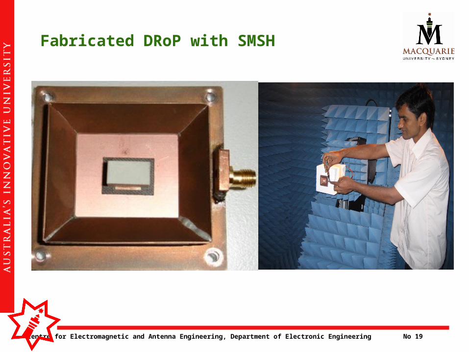
Fabricated DRoP with SMSH
Centre for Electromagnetic and Antenna Engineering, Department of Electronic Engineering No 20
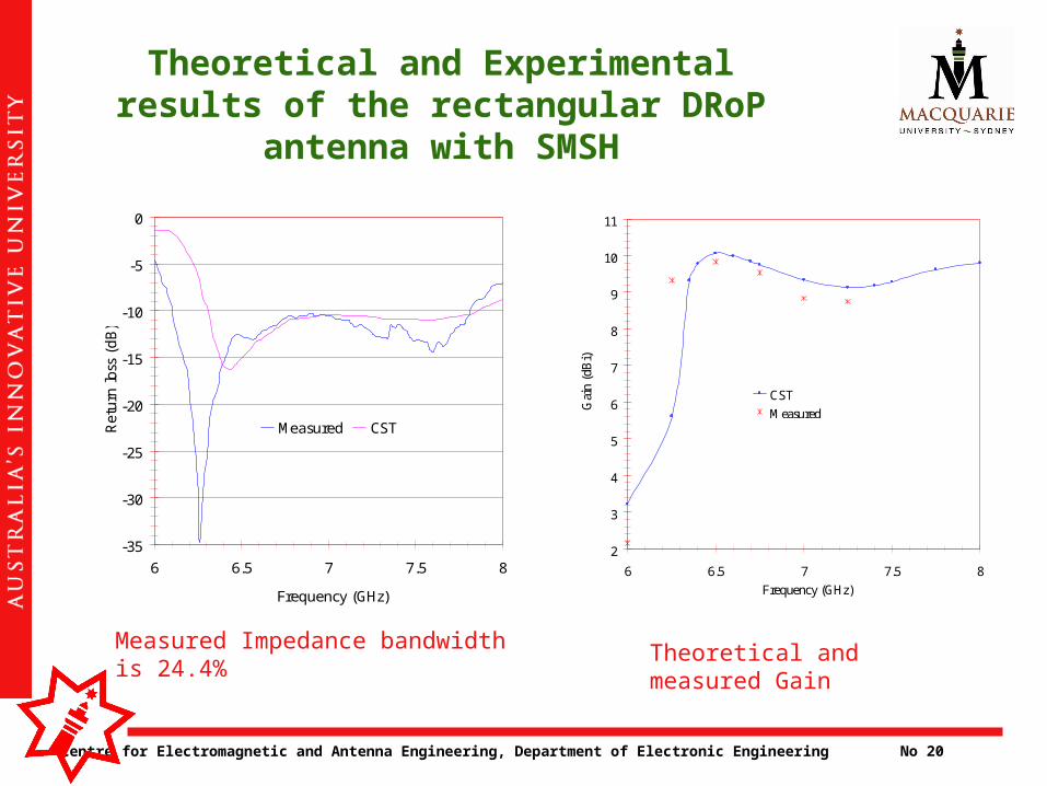
Theoretical and Experimental results of the rectangular DRoP
antenna with SMSH
-35
-30
-25
-20
-15
-10
-5
0
6 6.5 7 7.5 8
Frequency (GHz)
Ret
urn
loss
(dB)
Measured CST
Measured Impedance bandwidth is 24.4%
2
3
4
5
6
7
8
9
10
11
6 6.5 7 7.5 8
Frequency (GHz)G
ain
(dB
i)
CST
Measured
Theoretical and measured Gain
Centre for Electromagnetic and Antenna Engineering, Department of Electronic Engineering No 21
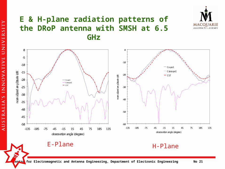
E & H-plane radiation patterns of the DRoP antenna with SMSH at 6.5
GHz
-50
-45
-40
-35
-30
-25
-20
-15
-10
-5
0
-135 -105 -75 -45 -15 15 45 75 105 135
observation angle (degree)
norm
aliz
ed a
mpl
itud
e (d
B)
Co-pol
Cross-pol
CST
-60
-50
-40
-30
-20
-10
0
-135 -105 -75 -45 -15 15 45 75 105 135
observation angle (degree)
norm
aliz
ed a
mpl
itud
e (d
B)
Co-pol
Cross-pol
CST
E-Plane H-Plane
Centre for Electromagnetic and Antenna Engineering, Department of Electronic Engineering No 22
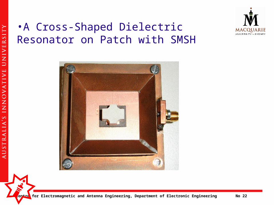
•A Cross-Shaped Dielectric Resonator on Patch with SMSH

Centre for Electromagnetic and Antenna Engineering, Department of Electronic Engineering No 23
0
1
2
3
4
5
6
7
8
5.5 6 6.5 7 7.5 8Frequency (GHz)
VSW
R
Rectangular DR on Patch
Cross DR on Patch
The measured 2:1VSWR impedance bandwidth of the rectangular DR on patch is 6.04 to 8.0 GHz (27.9%) and cross DR on patch is 23% (6.06GHz to 7.64GHz).
Comparison of rectangular and Cross-DR on patch: VSWR
Centre for Electromagnetic and Antenna Engineering, Department of Electronic Engineering No 24
3
4
5
6
7
8
9
10
11
6 6.5 7 7.5 8
Frequency (GHz)
Gai
n (d
Bi)
Rectangular DR on Patch
Cross DR on Patch
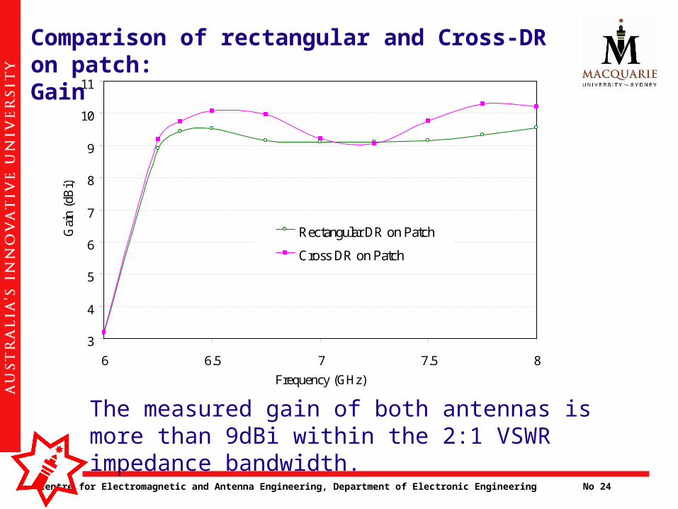
Comparison of rectangular and Cross-DR on patch:Gain
The measured gain of both antennas is more than 9dBi within the 2:1 VSWR impedance bandwidth.
Centre for Electromagnetic and Antenna Engineering, Department of Electronic Engineering No 25
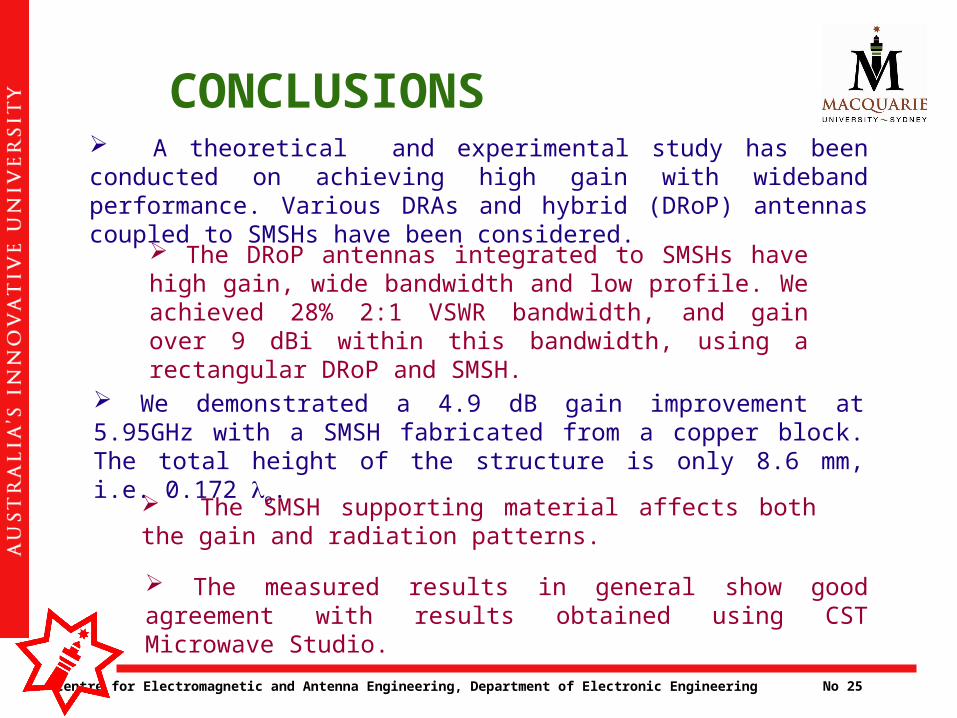
CONCLUSIONS A theoretical and experimental study has been conducted on achieving high gain with wideband performance. Various DRAs and hybrid (DRoP) antennas coupled to SMSHs have been considered.
The measured results in general show good agreement with results obtained using CST Microwave Studio.
We demonstrated a 4.9 dB gain improvement at 5.95GHz with a SMSH fabricated from a copper block. The total height of the structure is only 8.6 mm, i.e. 0.172 o.
The SMSH supporting material affects both the gain and radiation patterns.
The DRoP antennas integrated to SMSHs have high gain, wide bandwidth and low profile. We achieved 28% 2:1 VSWR bandwidth, and gain over 9 dBi within this bandwidth, using a rectangular DRoP and SMSH.