Embed Size (px)
DESCRIPTION
Soil MechanicsBasics
Citation preview
Soil Mechanics ICE‐222CE 222
Water in soil: Seepage and flow nets
1
Teton dam failure sequence 2
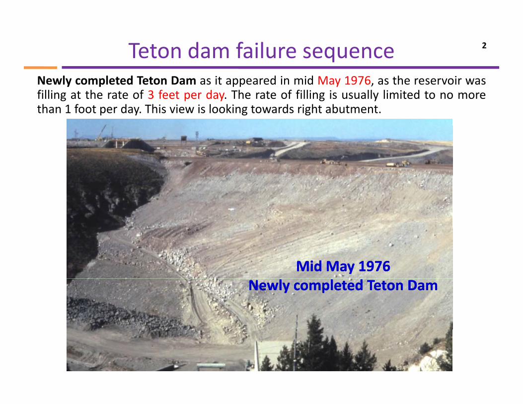
Newly completed Teton Dam as it appeared in mid May 1976, as the reservoir wasfilling at the rate of 3 feet per day. The rate of filling is usually limited to no morethan 1 foot per day. This view is looking towards right abutment.
Mid May 1976Mid May 1976Newly completed Teton DamNewly completed Teton Dam
Teton dam failure sequence 3
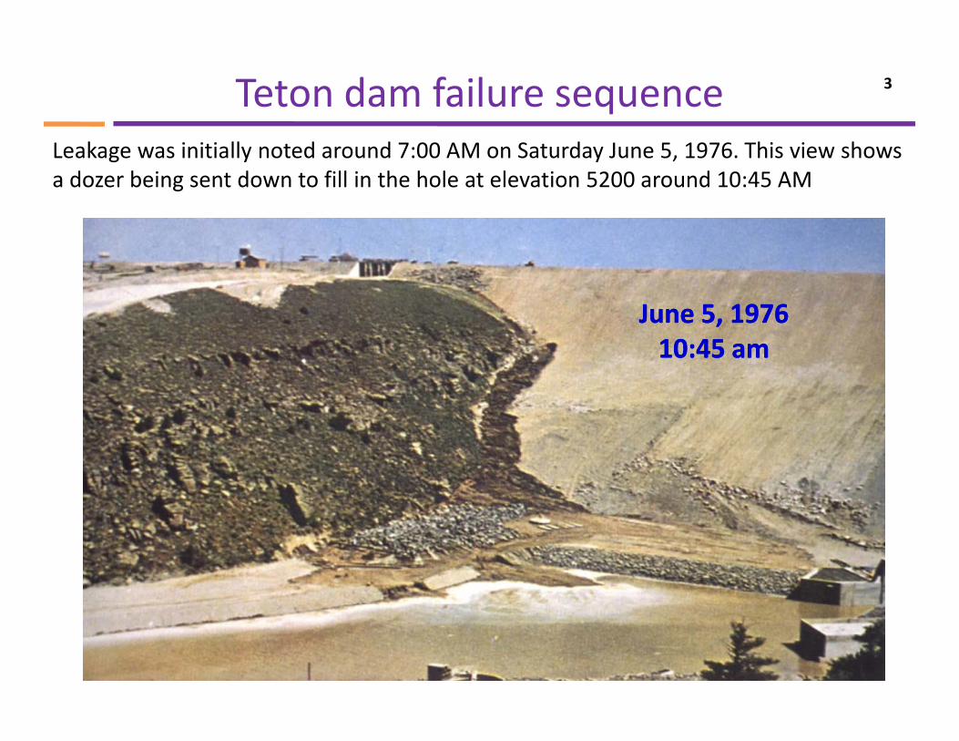
Leakage was initially noted around 7:00 AM on Saturday June 5, 1976. This view shows a dozer being sent down to fill in the hole at elevation 5200 around 10:45 AM
June 5, 1976June 5, 1976,,10:45 am10:45 am
Teton dam failure sequence 4
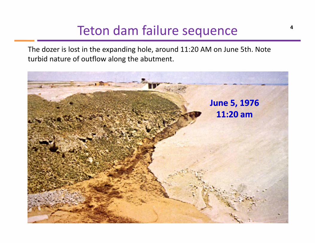
The dozer is lost in the expanding hole, around 11:20 AM on June 5th. Note turbid nature of outflow along the abutment.
June 5, 1976June 5, 1976,,11:20 am11:20 am
Teton dam failure sequence 5
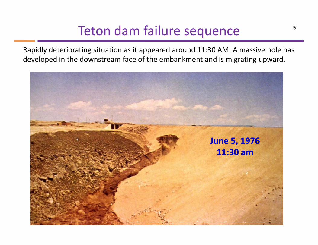
Rapidly deteriorating situation as it appeared around 11:30 AM. A massive hole has developed in the downstream face of the embankment and is migrating upward.
J 5 1976J 5 1976June 5, 1976June 5, 197611:30 am11:30 am
Teton dam failure sequence 6
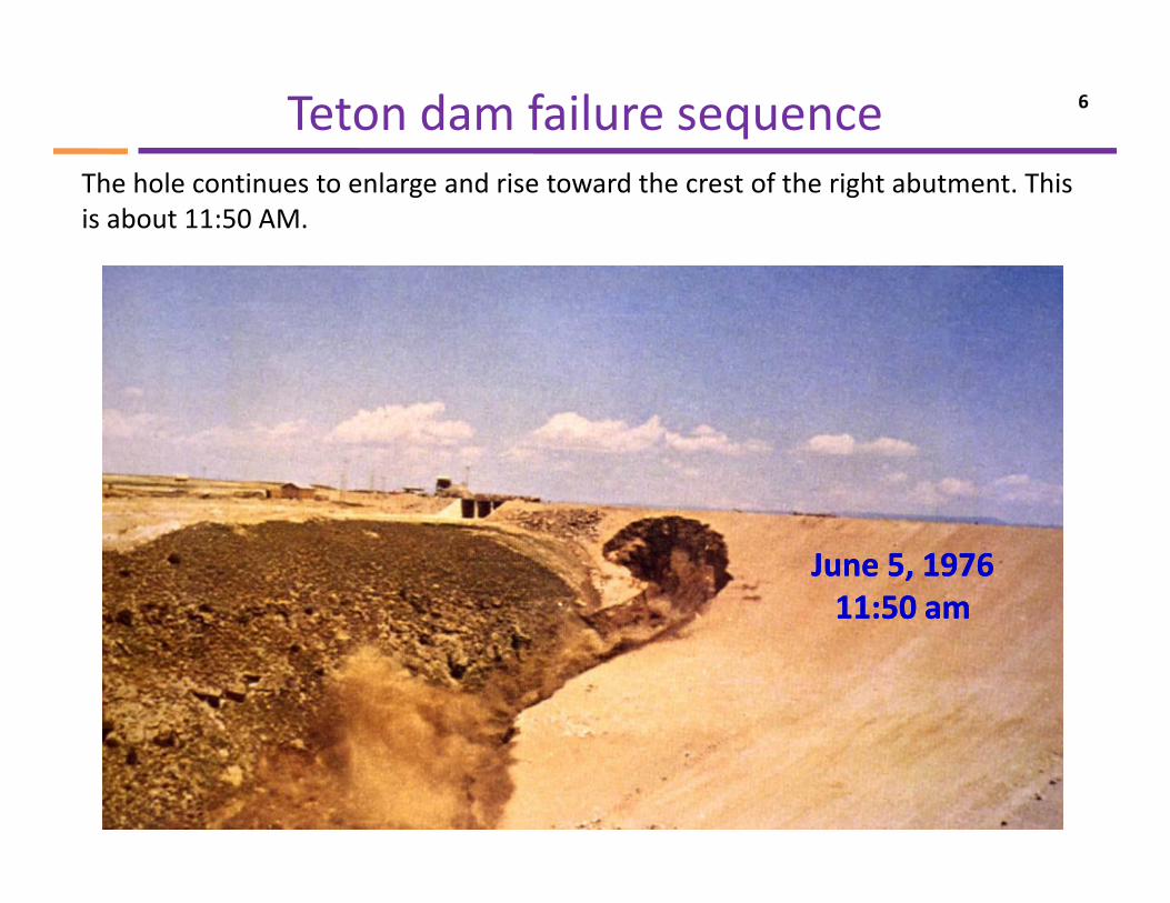
The hole continues to enlarge and rise toward the crest of the right abutment. This is about 11:50 AM.
June 5, 1976June 5, 197611:50 am11:50 am
Teton dam failure sequence 7
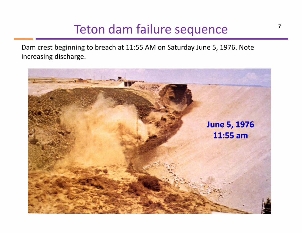
Dam crest beginning to breach at 11:55 AM on Saturday June 5, 1976. Note increasing discharge.
June 5, 1976June 5, 197611:55 am11:55 am
Teton dam failure sequence 8
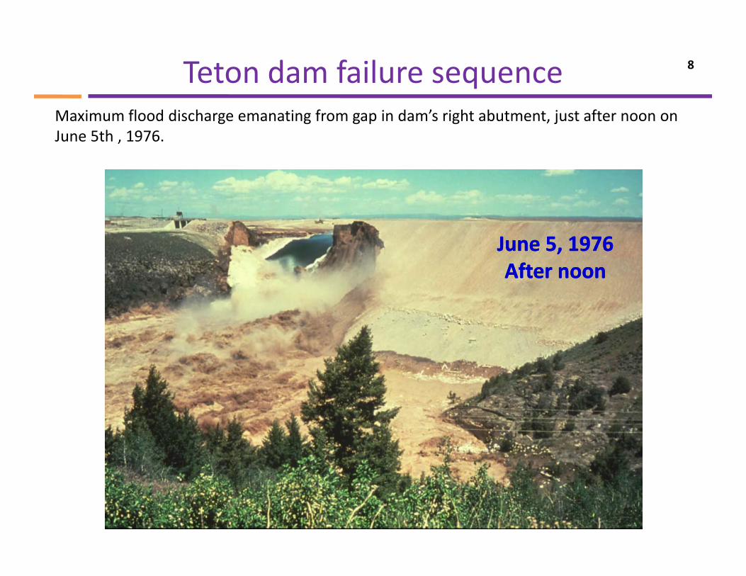
Maximum flood discharge emanating from gap in dam’s right abutment, just after noon on June 5th , 1976.
June 5, 1976June 5, 1976,,After noonAfter noon
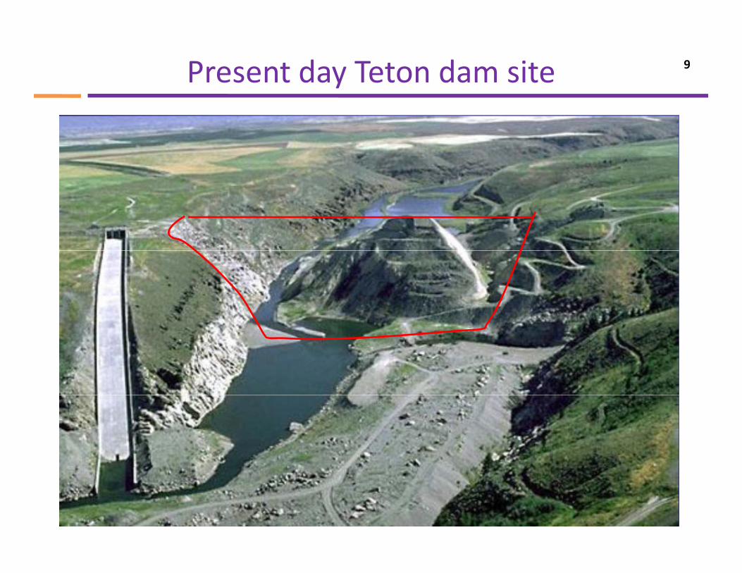
Present day Teton dam site 9
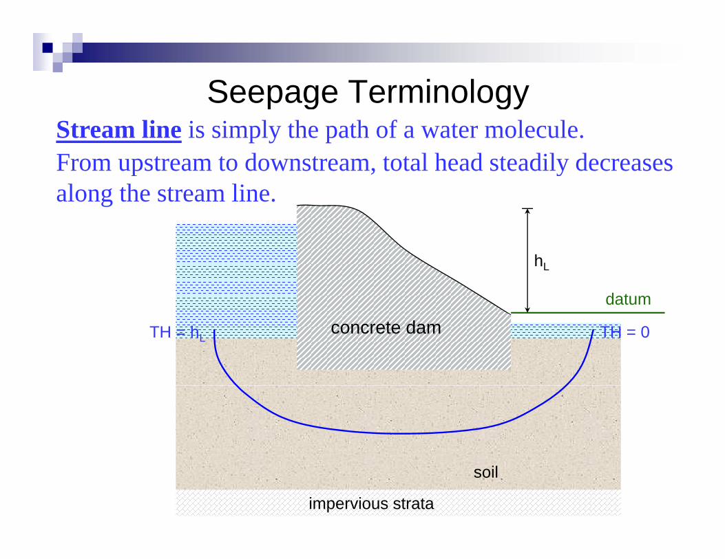
Seepage Terminologyp g gyStream line is simply the path of a water molecule.From upstream to downstream, total head steadily decreases p , yalong the stream line.
datum
hL
concrete dam TH = 0TH = hL
impervious strata
soil
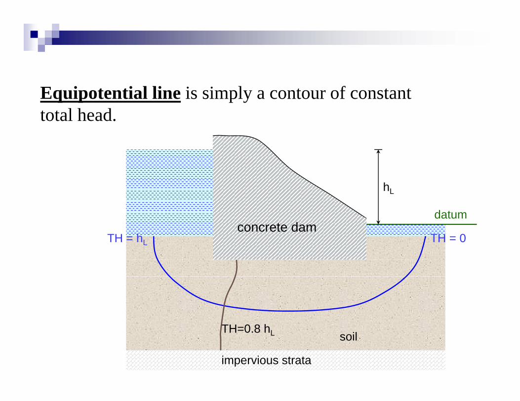
Equipotential line is simply a contour of constant total head.
concrete damdatum
hL
concrete damTH = 0TH = hL
TH=0 8 h
impervious strata
soilTH=0.8 hL
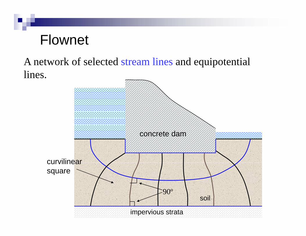
FlownetFlownetA network of selected stream lines and equipotential lineslines.
concrete damconcrete dam
curvilinearcurvilinear square
90º
impervious strata
soil90
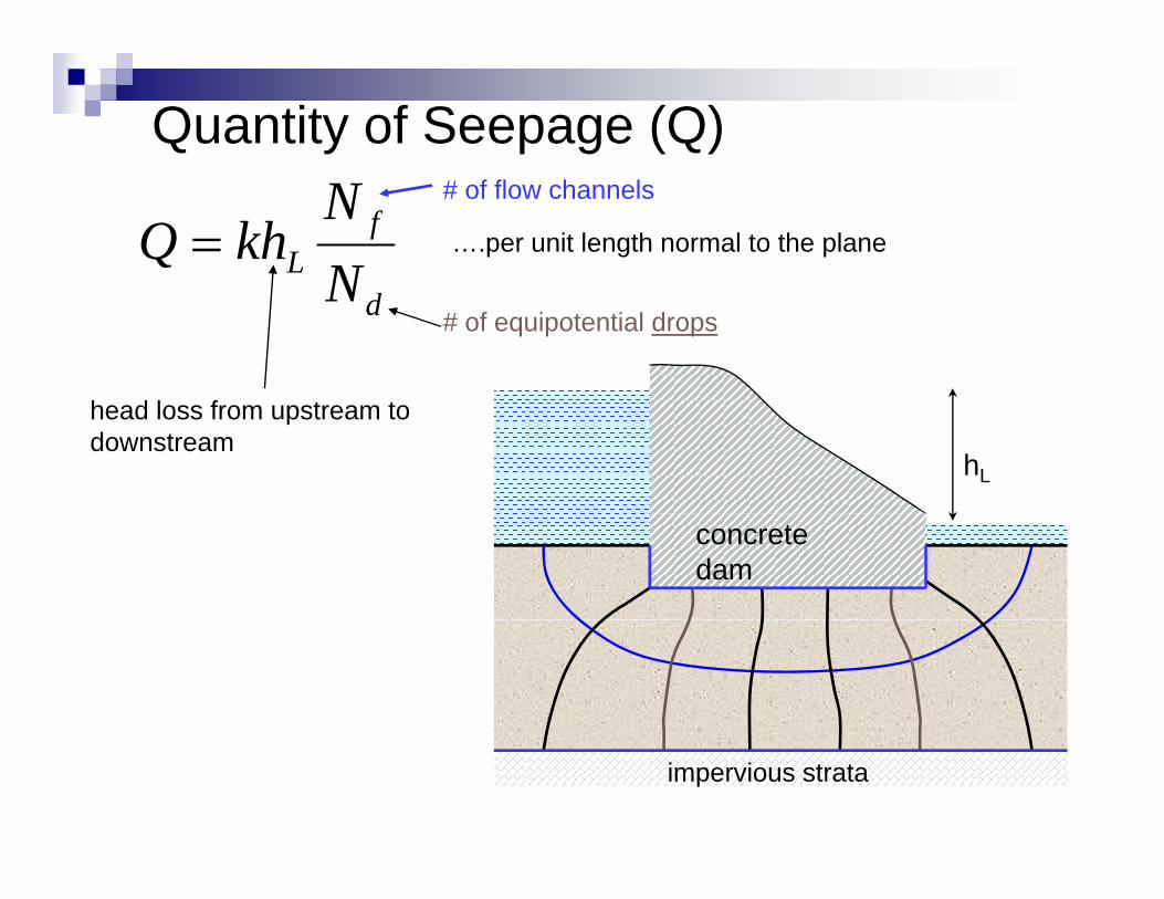
Quantity of Seepage (Q)
fL N
NkhQ = ….per unit length normal to the plane
# of flow channels
dN# of equipotential drops
hL
head loss from upstream to downstream
concrete dam
impervious strata
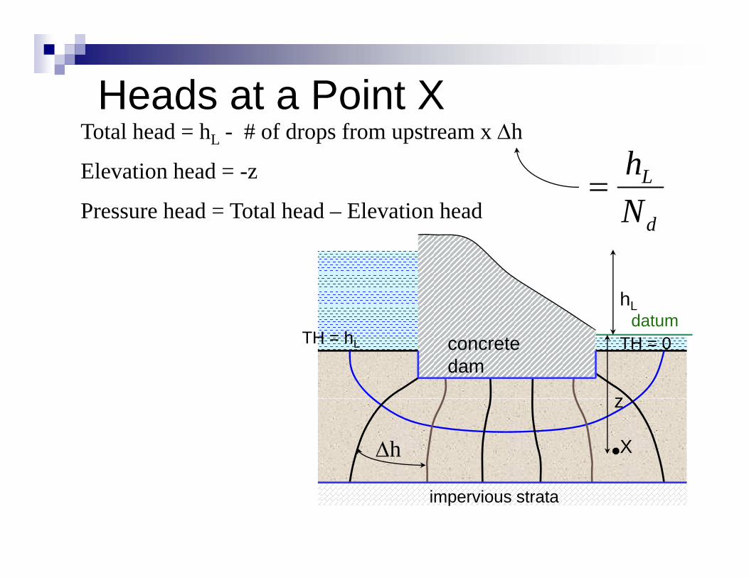
Heads at a Point XHeads at a Point XTotal head = hL - # of drops from upstream x Δh
Elevation head = -z LhPressure head = Total head – Elevation head d
L
N=
datumhL
concrete dam
datum
z
TH = hL TH = 0
X
z
Δh
impervious strata
Flow net 15
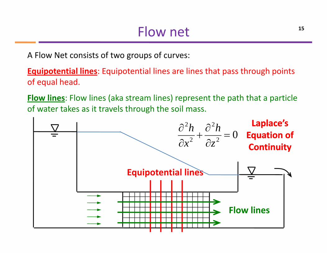
A Flow Net consists of two groups of curves:
Equipotential lines: Equipotential lines are lines that pass through points f l h dof equal head.
Flow lines: Flow lines (aka stream lines) represent the path that a particle of water takes as it travels through the soil massof water takes as it travels through the soil mass.
02
2
2
2
=∂∂
+∂∂
zh
xh Laplace’s Laplace’s
Equation of Equation of
Equipotential lines
∂∂ zx ContinuityContinuity
Equipotential lines
Flow lines
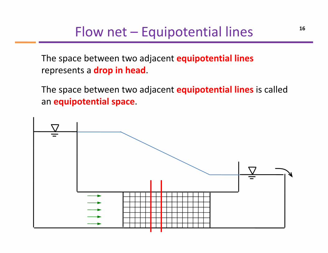
Flow net – Equipotential lines 16
The space between two adjacent equipotential lines represents a drop in head.
The space between two adjacent equipotential lines is called an equipotential space.
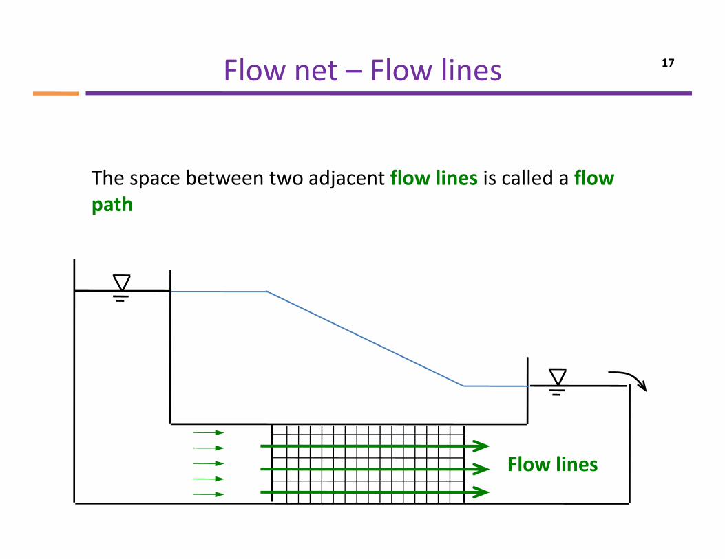
Flow net – Flow lines 17
Th b t t dj t fl li i ll d flThe space between two adjacent flow lines is called a flow path
Flow lines
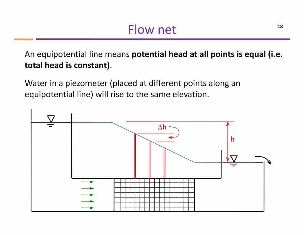
Flow net 18
An equipotential line means potential head at all points is equal (i.e. total head is constant).
Water in a piezometer (placed at different points along an equipotential line) will rise to the same elevation.
Δh
h
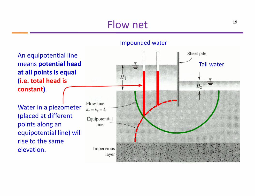
Flow net 19
An equipotential line
Impounded water
means potential head at all points is equal (i.e. total head is
Tail water
constant).
Water in a piezometer p(placed at different points along an equipotential line) will q p )rise to the same elevation.
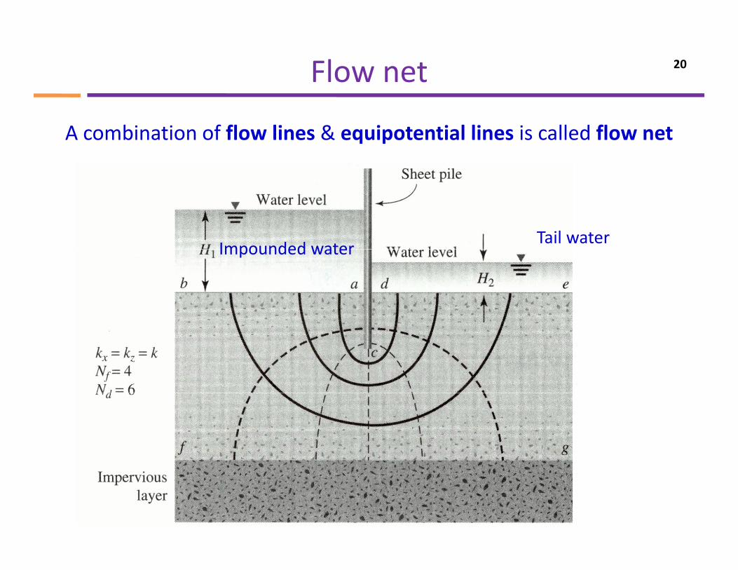
Flow net 20
A combination of flow lines & equipotential lines is called flow net
Impounded waterTail water
Impounded water
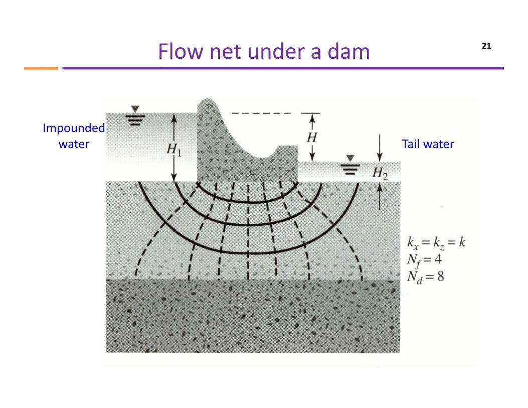
Flow net under a dam 21
ImpoundedImpounded water Tail water
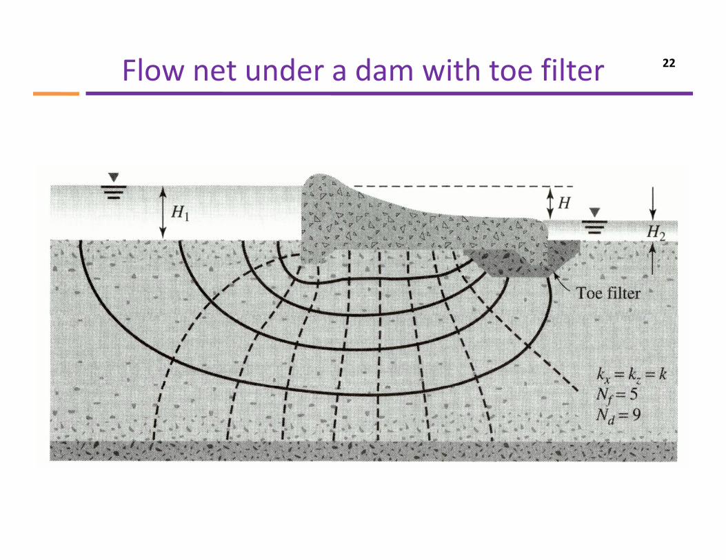
Flow net under a dam with toe filter 22
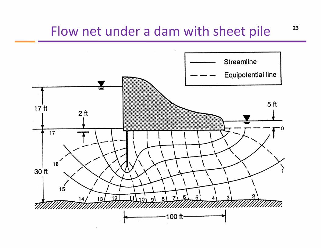
Flow net under a dam with sheet pile 23
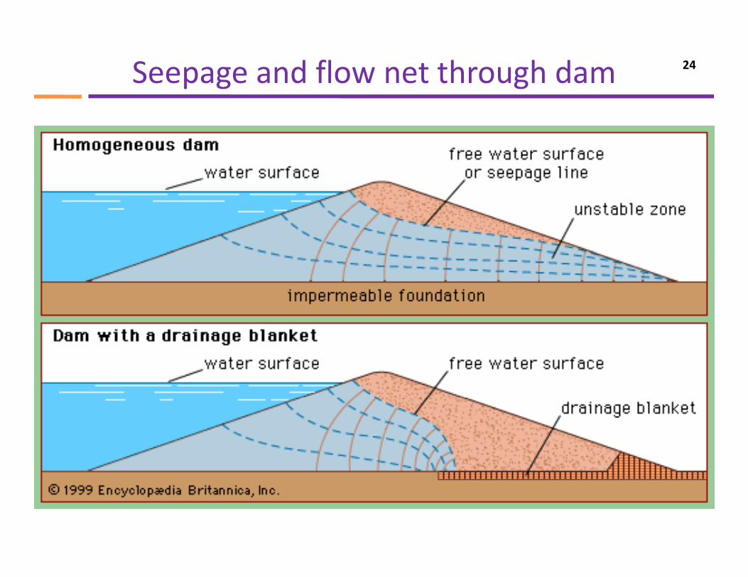
Seepage and flow net through dam 24
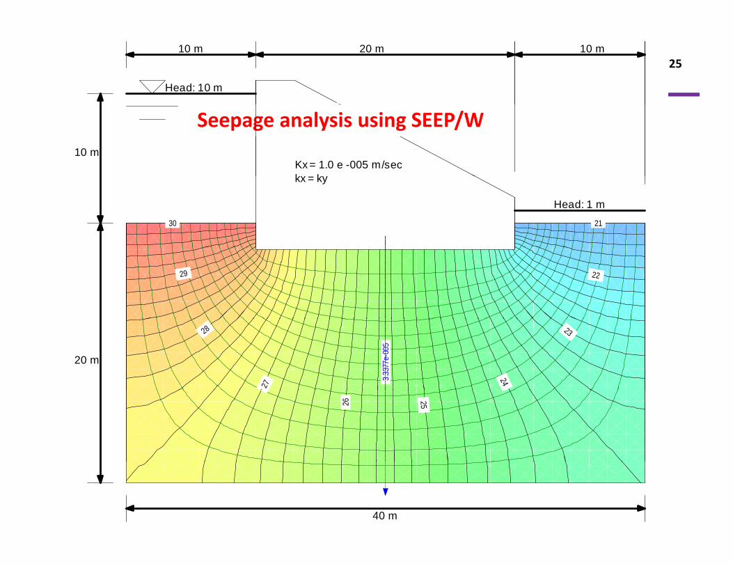
25
Head: 10 m
10 m 10 m20 m
10 mKx = 1.0 e -005 m/seck k
Seepage analysis using SEEP/W
kx = ky
Head: 1 m 21 30
22 29
20 m
23
24 27
28
3.33
77e-
005
25 26
40 m
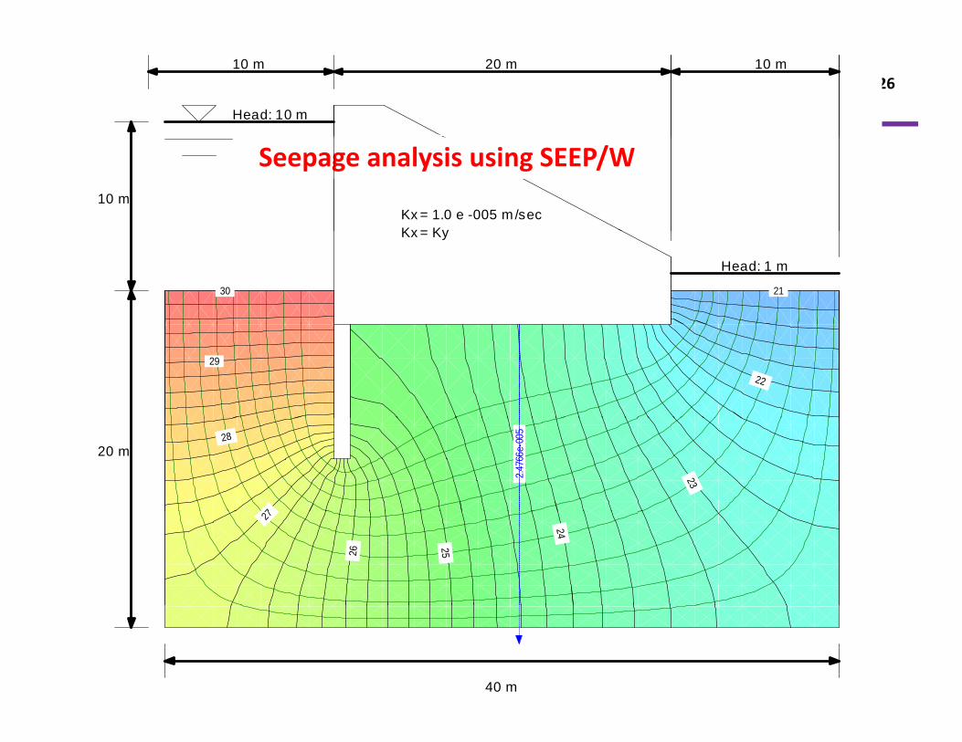
2610 m 20 m 10 m
Head: 10 m
10 mKx = 1.0 e -005 m/secKx = Ky
Seepage analysis using SEEP/W
Head: 1 m
Kx = Ky
21 30
22
29
20 m
23
7
28
2.4
766e
-005
24 25 26
27
40 m
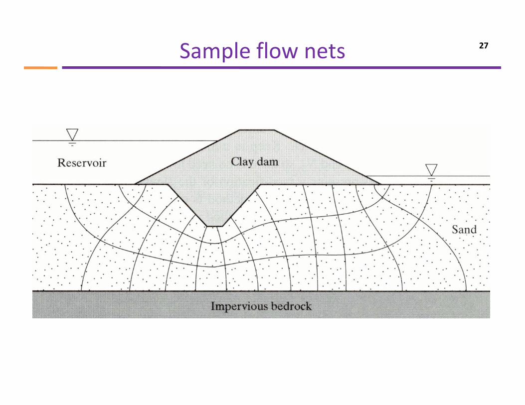
Sample flow nets 27
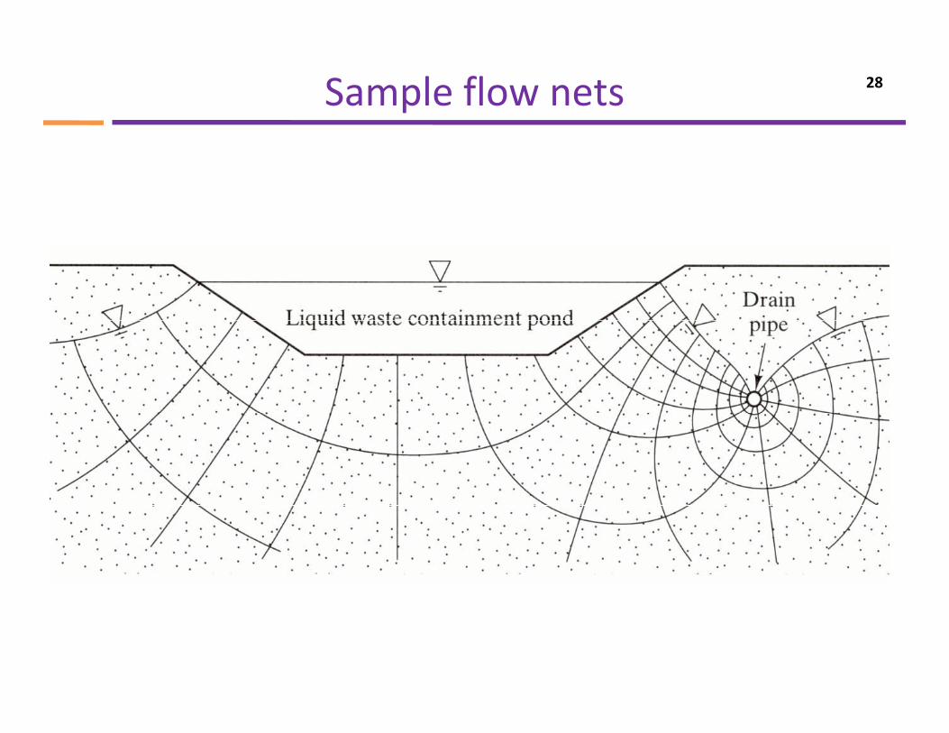
Sample flow nets 28
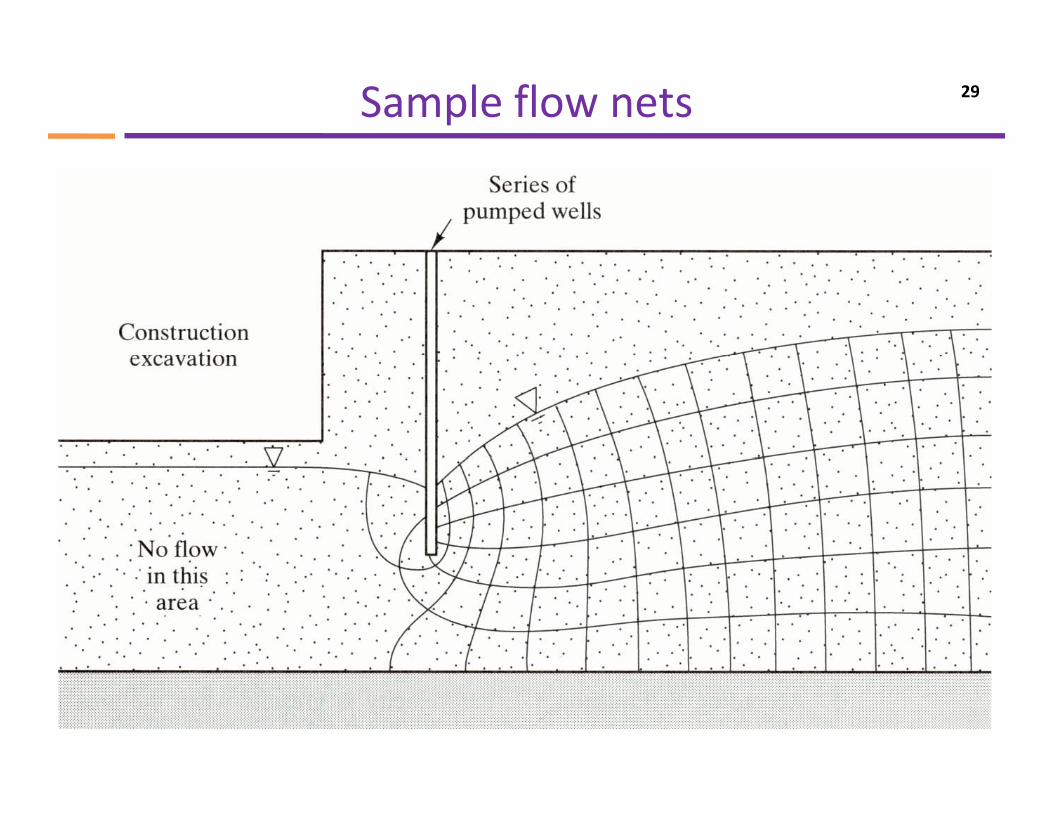
Sample flow nets 29
Construction of flow nets 30
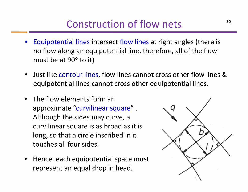
• Equipotential lines intersect flow lines at right angles (there is no flow along an equipotential line, therefore, all of the flow must be at 90° to it)must be at 90 to it)
• Just like contour lines, flow lines cannot cross other flow lines & equipotential lines cannot cross other equipotential linesequipotential lines cannot cross other equipotential lines.
• The flow elements form an approximate “curvilinear square”approximate curvilinear square . Although the sides may curve, a curvilinear square is as broad as it is long, so that a circle inscribed in it touches all four sides.
H h i i l• Hence, each equipotential space must represent an equal drop in head.
Construction of flow nets 31
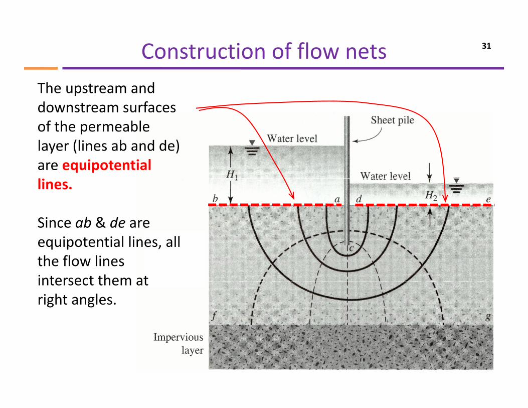
The upstream and downstream surfaces of the permeableof the permeable layer (lines ab and de) are equipotential llines.
Since ab & de are equipotential lines, all the flow lines intersect them atintersect them at right angles.
Construction of flow nets 32
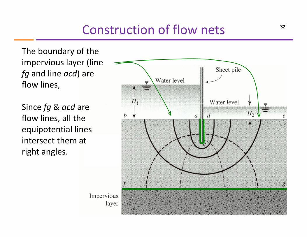
The boundary of the impervious layer (line fg and line acd) arefg and line acd) are flow lines,
f dSince fg & acd are flow lines, all the equipotential lines q pintersect them at right angles.
Seepage calculation from flow net 33
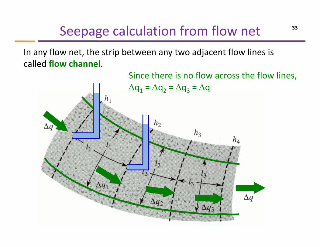
In any flow net, the strip between any two adjacent flow lines is called flow channel.
Since there is no flow across the flow linesSince there is no flow across the flow lines, Δq1 = Δq2 = Δq3 = Δq
Seepage calculation from flow net 34
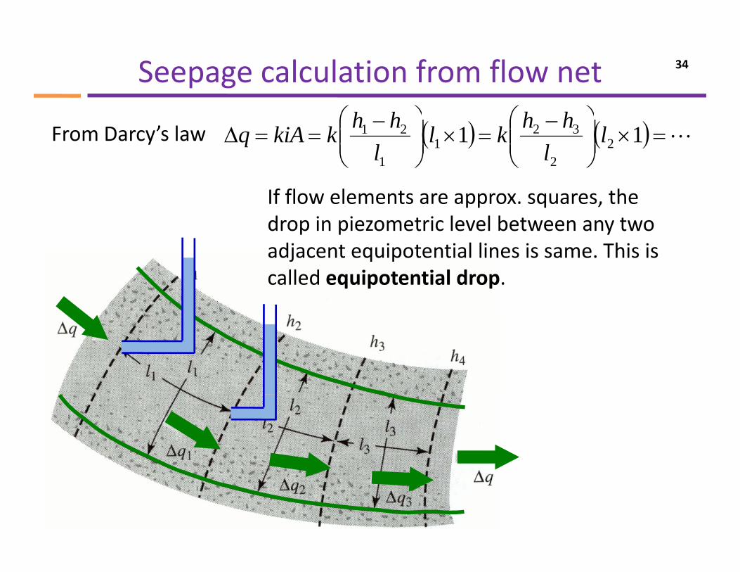
⎞⎛⎞⎛From Darcy’s law ( ) ( ) L=×⎟⎟
⎠
⎞⎜⎜⎝
⎛ −=×⎟⎟
⎠
⎞⎜⎜⎝
⎛ −==Δ 11 2
2
321
1
21 ll
hhkll
hhkkiAq
If flow elements are approx. squares, the drop in piezometric level between any two adjacent equipotential lines is same This isadjacent equipotential lines is same. This is called equipotential drop.
Seepage calculation from flow net 35
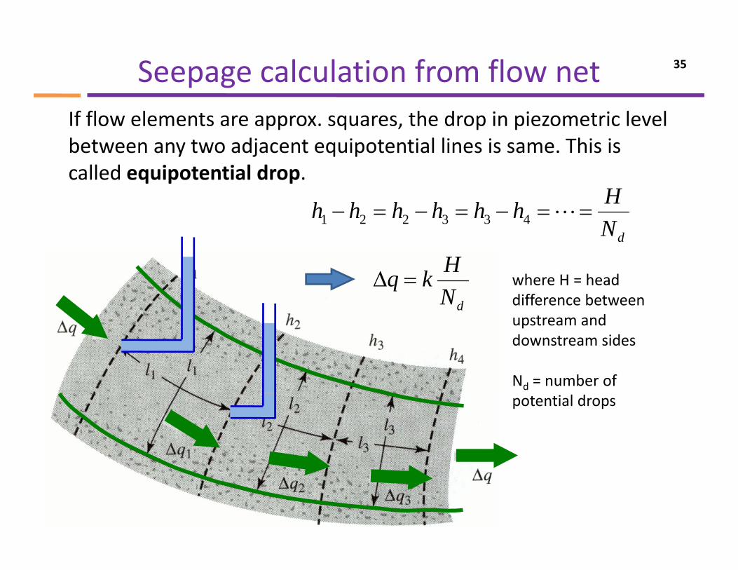
If flow elements are approx. squares, the drop in piezometric level between any two adjacent equipotential lines is same. This is called equipotential drop.
dNHhhhhhh ==−=−=− L433221
called equipotential drop.
dNHkq =Δ where H = head
difference between upstream andupstream and downstream sides
Nd = number of potential drops
Seepage calculation from flow net 36
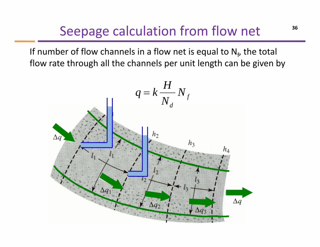
If number of flow channels in a flow net is equal to Nf, the total flow rate through all the channels per unit length can be given by
fd
NNHkq =
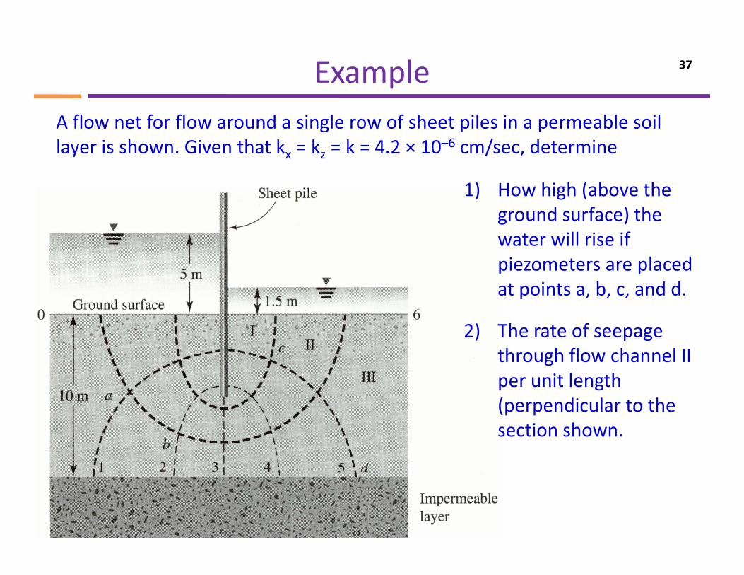
Example 37
A flow net for flow around a single row of sheet piles in a permeable soil layer is shown. Given that kx = kz = k = 4.2 × 10⁻⁶ cm/sec, determine
1) How high (above the ground surface) the water will rise if piezometers are placed at points a, b, c, and d.
2) h f2) The rate of seepage through flow channel II per unit length (perpendicular to the section shown.
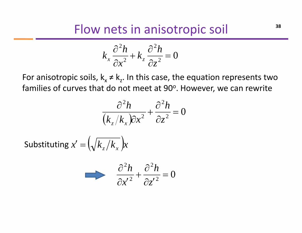
Flow nets in anisotropic soil 38
02
2
2
2
=∂∂
+∂∂
zhk
xhk zx
For anisotropic soils, kx ≠ kz. In this case, the equation represents two families of curves that do not meet at 90o. However, we can rewrite
22 ∂∂ hh( ) 02
2
2
2
=∂∂
+∂
∂zh
xkkh
xz
Substituting ( )xkkx xz=′
02
2
2
2
=′∂
∂+
′∂∂
zh
xh
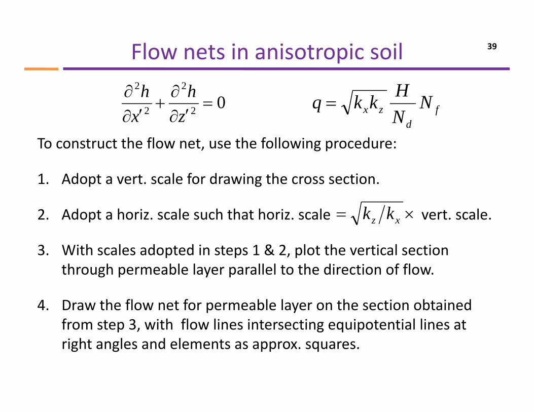
Flow nets in anisotropic soil 39
02
2
2
2
=′∂
∂+
′∂∂
zh
xh
fd
zx NNHkkq =
To construct the flow net, use the following procedure:
1 Adopt a vert scale for drawing the cross section1. Adopt a vert. scale for drawing the cross section.
2. Adopt a horiz. scale such that horiz. scale vert. scale.×= xz kk
3. With scales adopted in steps 1 & 2, plot the vertical section through permeable layer parallel to the direction of flow.
4. Draw the flow net for permeable layer on the section obtained from step 3, with flow lines intersecting equipotential lines at right angles and elements as approx. squares.
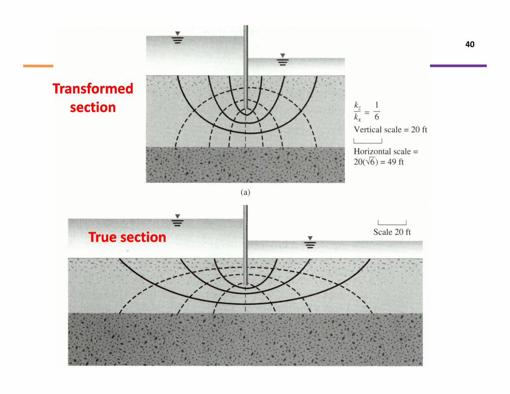
40
Transformed Transformed sectionsection
True sectionTrue section
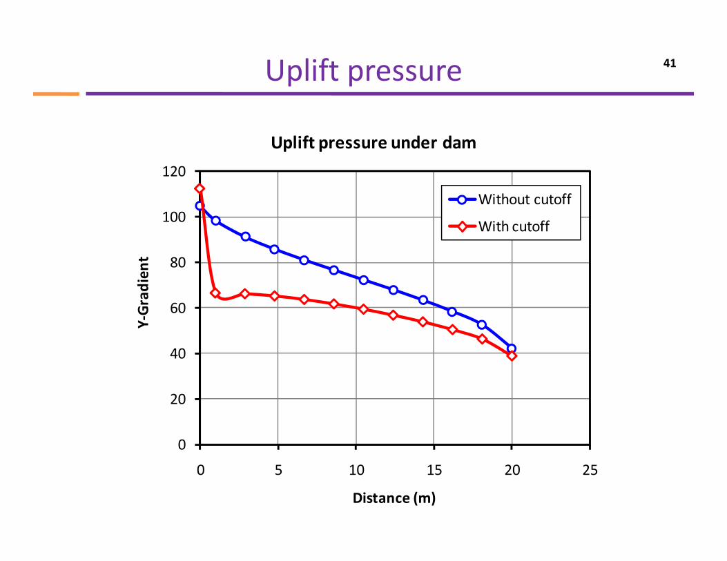
Uplift pressure 41
120
Uplift pressure under dam
100
120
Without cutoff
With cutoff
60
80
Gradien
t
40
Y‐
0
20
0 5 10 15 20 25
Distance (m)
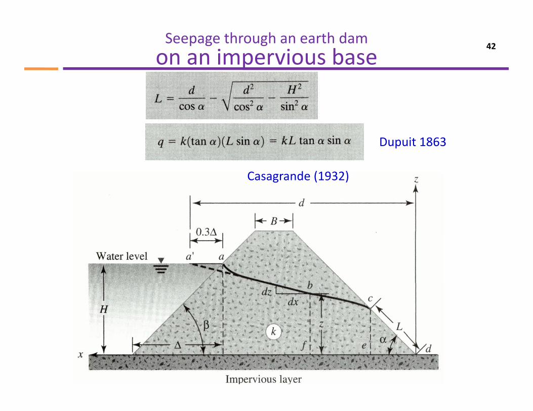
Seepage through an earth dam on an impervious base
42
Dupuit 1863
Casagrande (1932)Casagrande (1932)
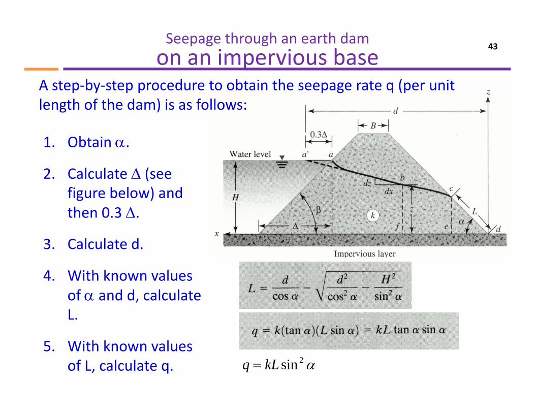
Seepage through an earth dam on an impervious base
43
A step‐by‐step procedure to obtain the seepage rate q (per unit length of the dam) is as follows:
1. Obtain α.
2. Calculate Δ (see (figure below) and then 0.3 Δ.
3. Calculate d.
4. With known values of α and d, calculate L.
5. With known values of L, calculate q. α2sinkLq =
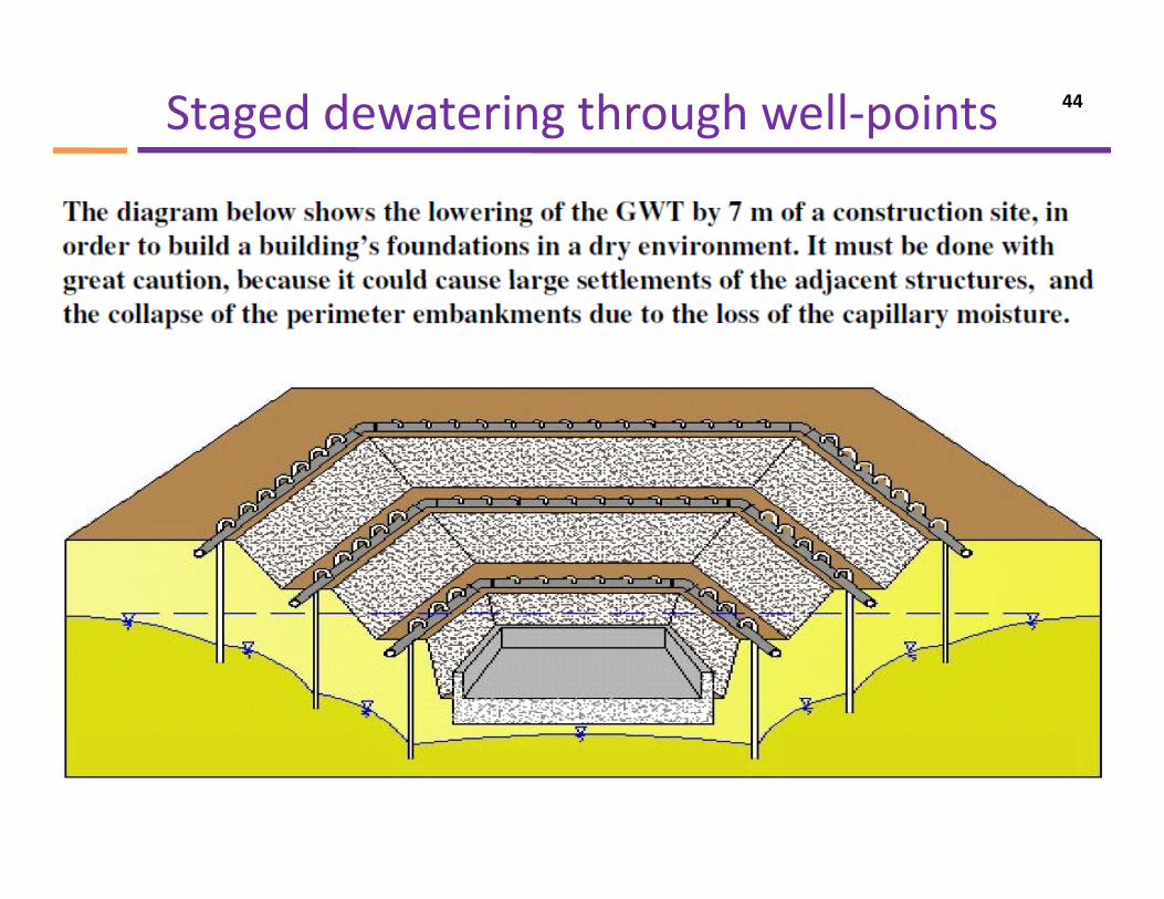
Staged dewatering through well‐points 44
Illustrations of flow nets
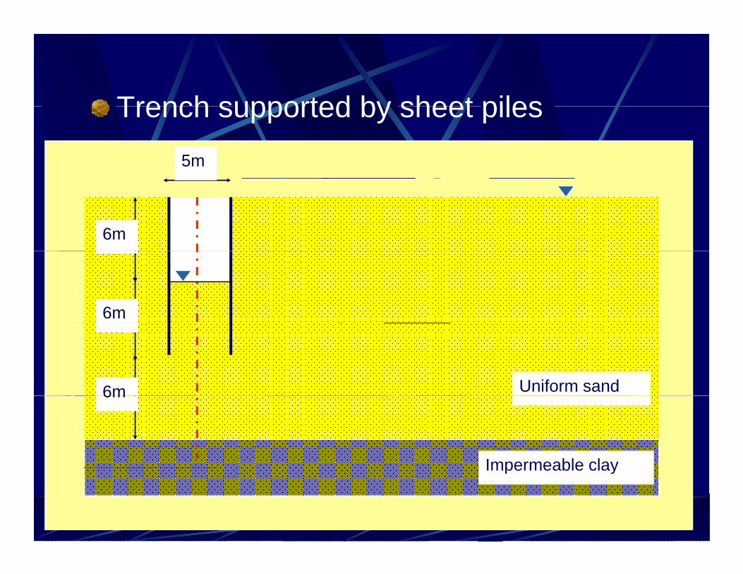
Trench supported by sheet pilesTrench supported by sheet piles5m
6m
6m
Uniform sand6m
Impermeable clay
6m
Impermeable clay
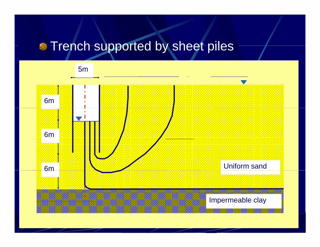
Trench supported by sheet pilesTrench supported by sheet piles5m
6m
6m
Uniform sand6m
Impermeable clay
6m
Impermeable clay
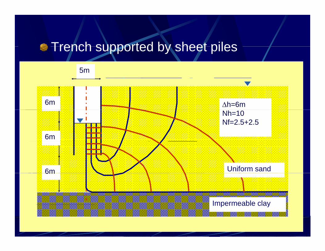
Trench supported by sheet pilesTrench supported by sheet piles5m
6m Δh=6m
6m
Nh=10Nf=2.5+2.5
6m Uniform sand
Impermeable clay
6m
Impermeable clay
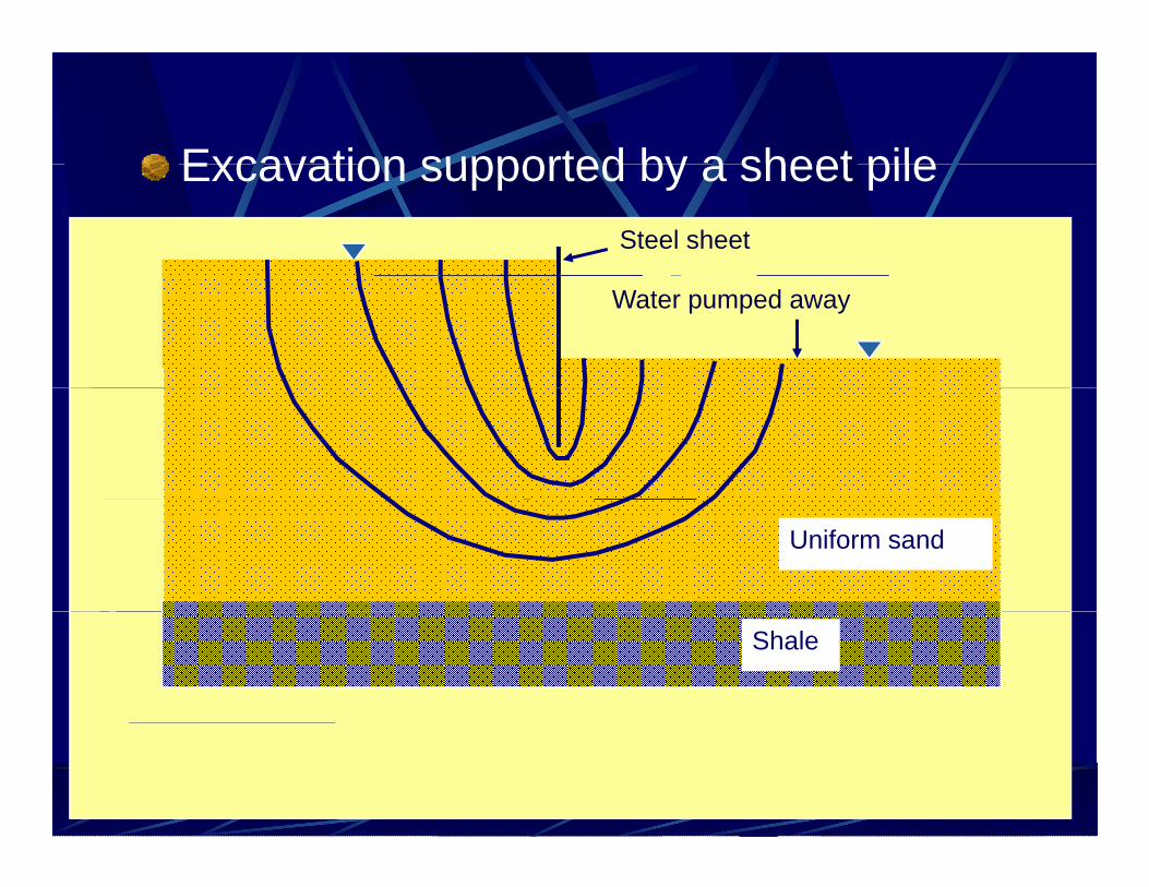
Excavation supported by a sheet pileExcavation supported by a sheet pileSteel sheet
Water pumped away
Uniform sand
Shale
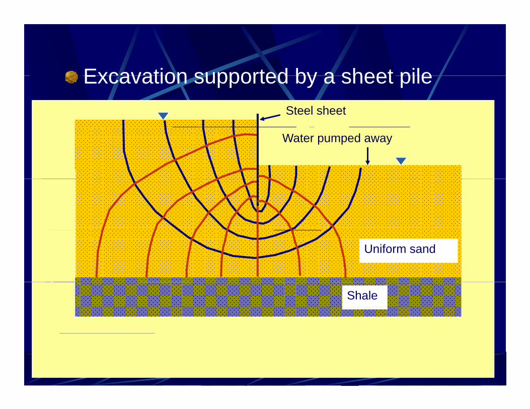
Excavation supported by a sheet pileExcavation supported by a sheet pileSteel sheet
Water pumped away
Uniform sand
Shale
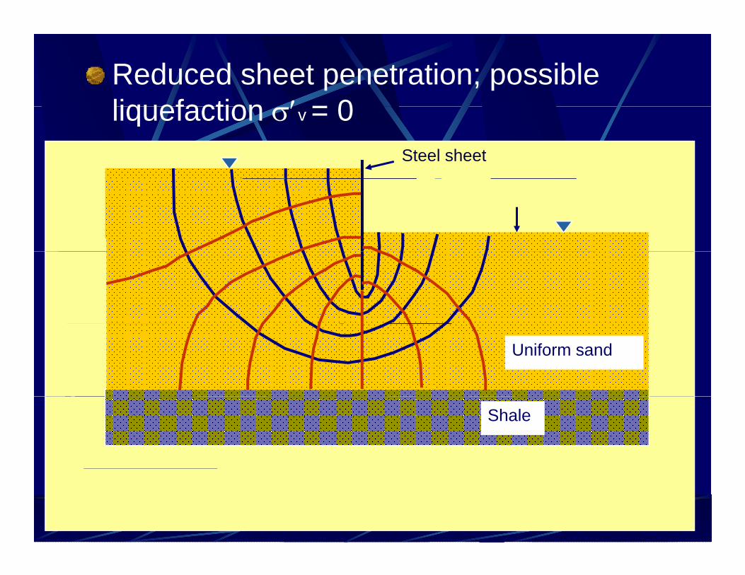
Reduced sheet penetration; possible liquefaction ′ = 0liquefaction σ′v = 0
Steel sheet
Uniform sand
Shale
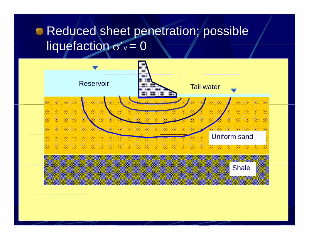
Reduced sheet penetration; possible liquefaction ′ = 0liquefaction σ′v = 0
Reservoir Tail water
U if dUniform sand
Shale
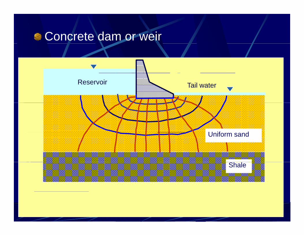
Concrete dam or weir
Reservoir Tail water
U if dUniform sand
Shale
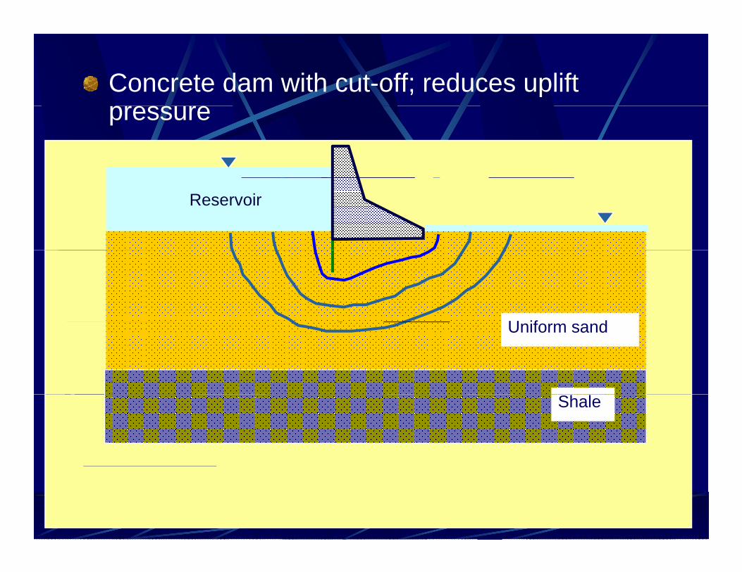
Concrete dam with cut-off; reduces uplift pressure
Reservoir
U if dUniform sand
Shale

Concrete dam with cut-off; reduces uplift pressure
Reservoir
U if dUniform sand
Shale
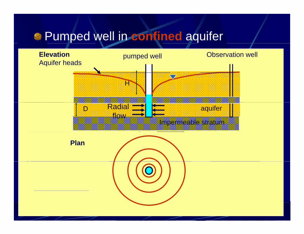
Pumped well in confined aquiferObservation wellpumped wellElevation
Aquifer heads
H
D aquiferRadial flow
Impermeable stratum
Plan

Pumped well in confined aquiferObservation wellpumped wellElevation
Aquifer heads
H
D aquiferRadial flow
Impermeable stratum
Plan
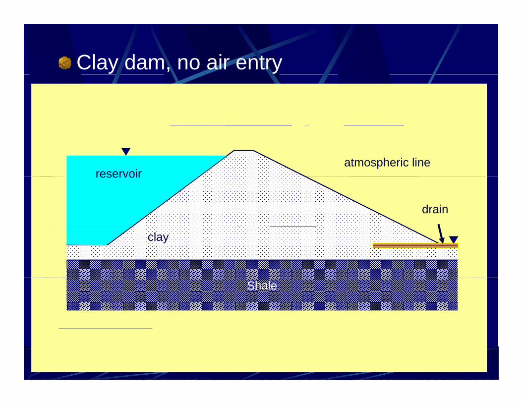
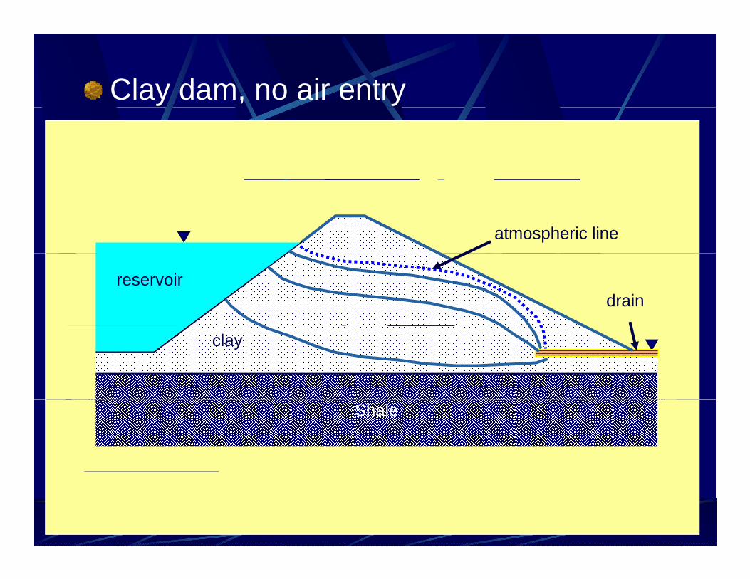
Clay dam, no air entry
reservoiratmospheric line
reservoir
drain
clay
Shale
Clay dam, no air entry
atmospheric line
drainreservoir
clay
Shale
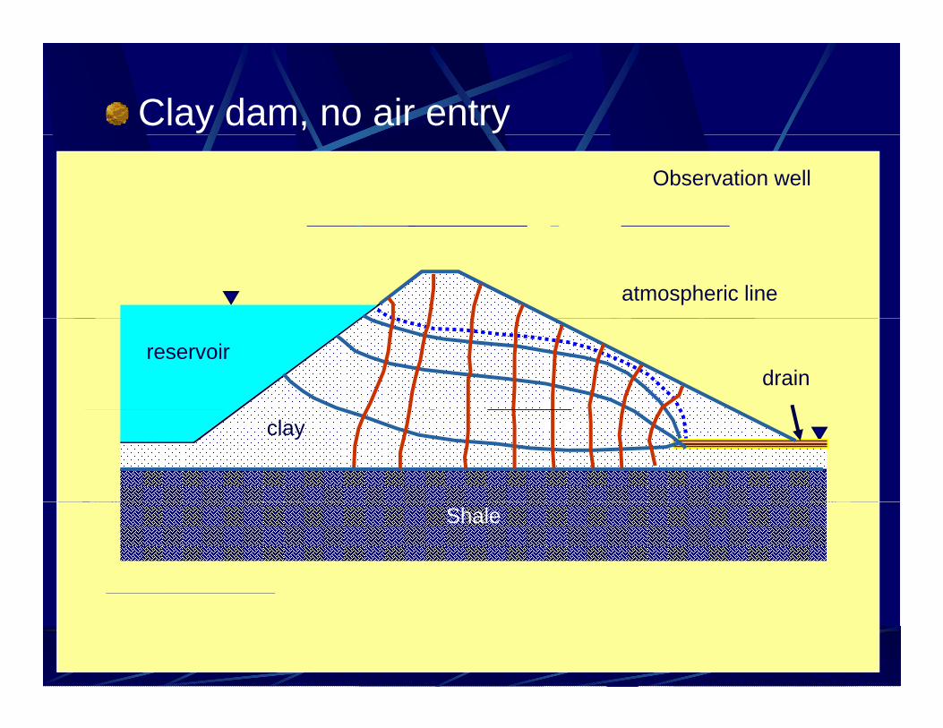
Clay dam, no air entryObservation well
atmospheric line
drainreservoir
clay
Shale
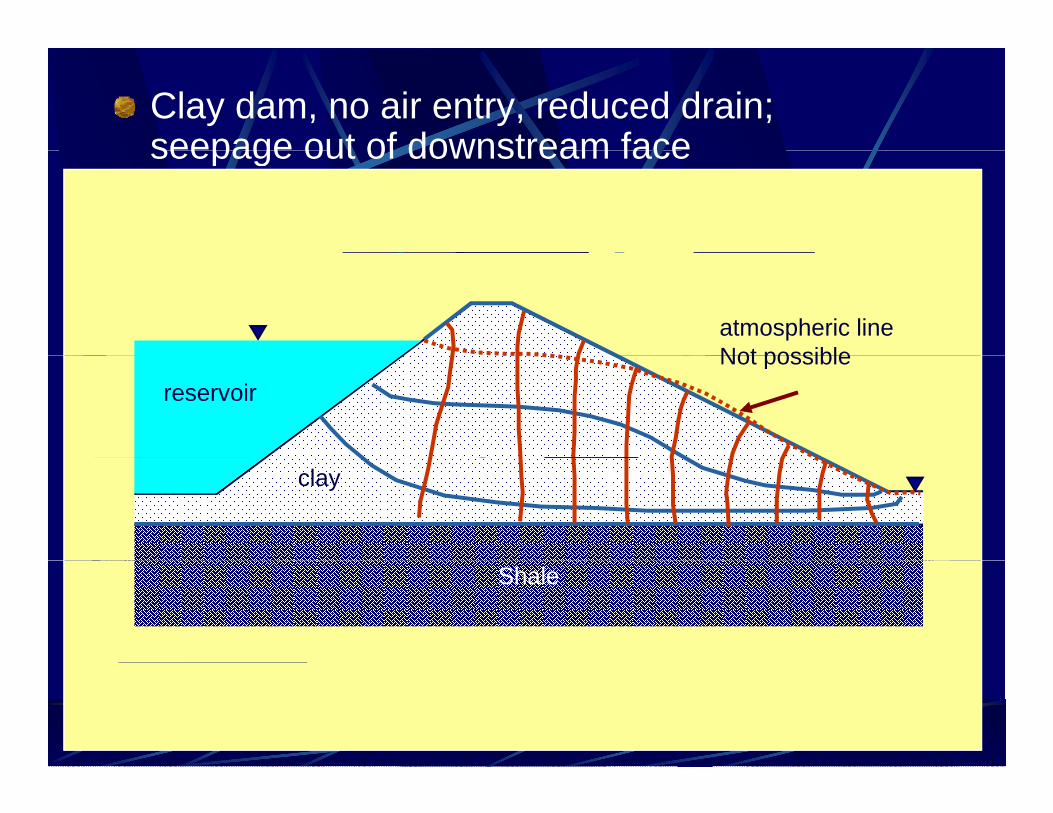
Clay dam, no air entry, reduced drain; seepage out of downstream faceseepage out of downstream face
atmospheric lineNot possibleNot possible
reservoir
clay
Shale
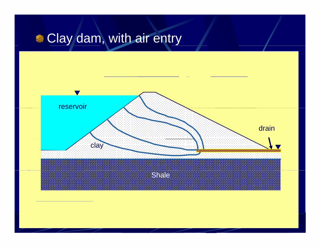
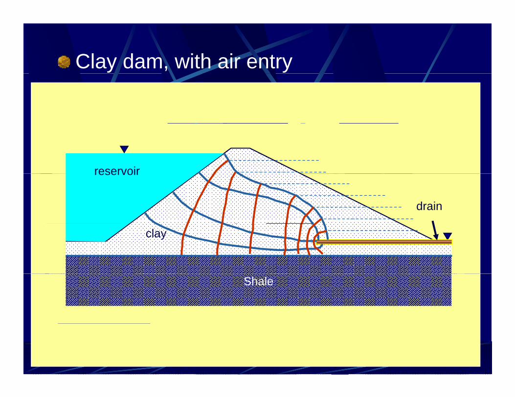
Clay dam, with air entry
reservoirreservoir
drain
clay
Shale
Clay dam, with air entry
reservoirreservoir
drain
clay
Shale

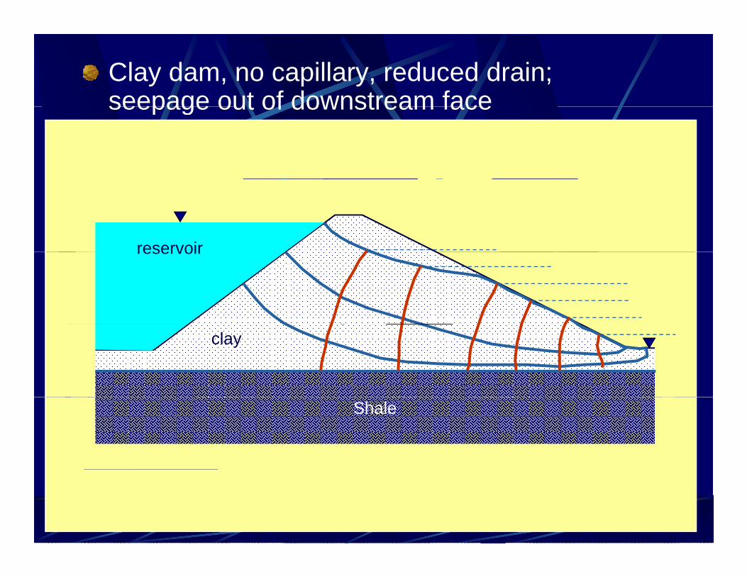
Clay dam, no capillary, reduced drain; seepage out of downstream faceseepage out of downstream face
reservoirreservoir
clay
Shale
Clay dam, no capillary, reduced drain; seepage out of downstream faceseepage out of downstream face
reservoirreservoir
clay
Shale