Embed Size (px)
Citation preview

SPORTON INTERNATIONAL INC. Page Number : 1 of 46
TEL : 886-3-327-3456 Report Issued Date : Jun. 12, 2017
FAX : 886-3-328-4978 Report Version : Rev. 01
Report Template No.: BU5-ER328 2024 Version 1.1
CE Radio Test Report Report No. : ER741317
CE Radio Test Report
APPLICANT : Texas Instruments Incorporated
EQUIPMENT : CC3100MODR11MAMOB
BRAND NAME : Texas Instruments
MODEL NAME : CC3100MODR11MAMOB
MARKETING NAME : SimpleLink™ Wi-Fi® CC3100MOD
Wireless Network Processor Module
STANDARD : ETSI EN 300 328 V2.1.1 (2016-11)
TEST DATE(S) : May 10, 2017 ~ Jun. 07, 2017
The measurement shown in this test report is tested in accordance with
the test procedures given in ETSI EN 300 328 V2.1.1 (2016-11).
The test results in this report apply exclusively to the tested model / sample.
Without written approval of SPORTON INTERNATIONAL INC., the test report
shall not be reproduced except in full.
Reviewed by: Joseph Lin / Supervisor
Approved by: Jones Tsai / Manager
SPORTON INTERNATIONAL INC. No. 52, Hwa Ya 1st Rd.,Hwa Ya Technology Park, Kwei-Shan District, Tao Yuan City, Taiwan R.O.C.
Draft R
eport
SPORTON INTERNATIONAL INC. Page Number : 2 of 46
TEL : 886-3-327-3456 Report Issued Date : Jun. 12, 2017
FAX : 886-3-328-4978 Report Version : Rev. 01
Report Template No.: BU5-ER328 2024 Version 1.1
CE Radio Test Report Report No. : ER741317
TABLE OF CONTENTS
REVISION HISTORY .......................................................................................................................................... 3
SUMMARY OF TEST RESULT ......................................................................................................................... 4
1 GENERAL DESCRIPTION .......................................................................................................................... 5
1.1 Applicant ............................................................................................................................................ 5 1.2 Manufacturer ...................................................................................................................................... 5 1.3 Product Feature of Equipment Under Test ........................................................................................ 5 1.4 Modification of EUT ........................................................................................................................... 5 1.5 Testing Facility ................................................................................................................................... 6 1.6 Applied Standards ............................................................................................................................. 6 1.7 Test Condition .................................................................................................................................... 6
2 TEST CONFIGURATION OF EQUIPMENT UNDER TEST ........................................................................ 7
2.1 Descriptions of Test Mode ................................................................................................................. 7 2.2 Connection Diagram of EUT Test Configurations ............................................................................. 8 2.3 Supported Unit used in test configuration and system ...................................................................... 8 2.4 EUT Operation Test Setup ................................................................................................................ 8
3 TRANSMITTER PARAMETERS ................................................................................................................. 9
3.1 Maximum Transmit Power ................................................................................................................. 9 3.2 Maximum Equivalent Isotropically Radiated Power (E.I.R.P.) Spectral Density ............................. 10 3.3 Occupied Channel Bandwidth ......................................................................................................... 12 3.4 Transmitter unwanted emissions in the out-of-band domain .......................................................... 14 3.5 Transmitter spurious emissions ....................................................................................................... 16
4 RECEIVER PARAMETERS ....................................................................................................................... 18
4.1 Receiver spurious emissions ........................................................................................................... 18 4.2 Receiver Blocking Test .................................................................................................................... 20
5 ADAPTIVITY TEST .................................................................................................................................... 24
5.1 Adaptivity ......................................................................................................................................... 24
6 GEO-LOCATION CAPABILITY ................................................................................................................. 44
6.1 Geo-location .................................................................................................................................... 44
7 LIST OF MEASURING EQUIPMENT ........................................................................................................ 45
8 UNCERTAINTY EVALUATION ................................................................................................................. 46
APPENDIX A. TEST RESULT OF CONDUCTED TEST ITEMS
APPENDIX B. CONDUCTED SPURIOUS EMISSION PLOTS
APPENDIX C. CABINET RADIATION PLOTS
APPENDIX D. PHOTOGRAPHS OF RADIATED EMISSION TEST CONFIGURATION
Draft R
eport

SPORTON INTERNATIONAL INC. Page Number : 3 of 46
TEL : 886-3-327-3456 Report Issued Date : Jun. 12, 2017
FAX : 886-3-328-4978 Report Version : Rev. 01
Report Template No.: BU5-ER328 2024 Version 1.1
CE Radio Test Report Report No. : ER741317
REVISION HISTORY
REPORT NO. VERSION DESCRIPTION ISSUED DATE
ER741317 Rev. 01 Initial issue of report Jun. 12, 2017
Draft R
eport

SPORTON INTERNATIONAL INC. Page Number : 4 of 46
TEL : 886-3-327-3456 Report Issued Date : Jun. 12, 2017
FAX : 886-3-328-4978 Report Version : Rev. 01
Report Template No.: BU5-ER328 2024 Version 1.1
CE Radio Test Report Report No. : ER741317
SUMMARY OF TEST RESULT
CLAUSE
(EN 300 328) TEST PARAMETER PASS/FAIL REMARK
Transmitter Parameters
4.3.1.2
4.3.2.2 Maximum Transmit Power PASS -
4.3.2.3 Maximum Equivalent Isotropically Radiated
Power (E.I.R.P.) Spectral Density PASS
Only applicable for modulations
other than FHSS
4.3.1.8
4.3.2.7 Occupied Channel Bandwidth PASS -
4.3.1.4
4.3.1.5 Frequency Hopping Requirements Not Required Only applicable for FHSS
4.3.1.9
4.3.2.8 Transmitter spurious emissions in OOB PASS -
4.3.1.10
4.3.2.9 Transmitter spurious emissions PASS
Under limit 10.46 dB
at 6993.000 MHz
Receiver Parameters
4.3.1.11
4.3.2.10 Receiver spurious emissions PASS
Under limit 6.53 dB
at 2396.000 MHz
Adaptive Test Item
4.3.1.7
4.3.2.6 Adaptivity PASS Only applicable for
adaptive equipment
Output Power >10dBm 4.3.1.12
4.3.2.11 Receiver Blocking PASS
Non-Adaptive Test Item
4.3.1.3
4.3.2.4 Duty cycle, Tx-Sequence, Tx-gap Not Required Only applicable for
non-adaptive equipment
Output Power >10dBm 4.3.1.6
4.3.2.5 Medium Utilisation (MU) factor Not Required
Note: WiFi belongs to adaptive equipment and EIRP > 10dBm.
Draft R
eport

SPORTON INTERNATIONAL INC. Page Number : 5 of 46
TEL : 886-3-327-3456 Report Issued Date : Jun. 12, 2017
FAX : 886-3-328-4978 Report Version : Rev. 01
Report Template No.: BU5-ER328 2024 Version 1.1
CE Radio Test Report Report No. : ER741317
1 General Description
1.1 Applicant
Texas Instruments Incorporated
12500 TI BLVD., Dallas Texas, 75243
1.2 Manufacturer
Texas Instruments Incorporated
12500 TI BLVD., Dallas Texas, 75243
1.3 Product Feature of Equipment Under Test
Wi-Fi 2.4GHz 802.11b/g/n.
Product Specification subjective to this standard
Antenna Type WLAN: Chip Antenna
1.4 Modification of EUT
No modifications are made to the EUT during all test items.
Draft R
eport
SPORTON INTERNATIONAL INC. Page Number : 6 of 46
TEL : 886-3-327-3456 Report Issued Date : Jun. 12, 2017
FAX : 886-3-328-4978 Report Version : Rev. 01
Report Template No.: BU5-ER328 2024 Version 1.1
CE Radio Test Report Report No. : ER741317
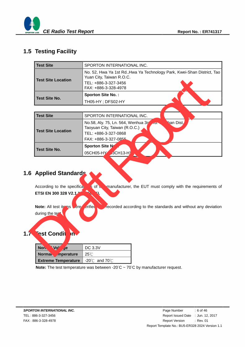
1.5 Testing Facility
Test Site SPORTON INTERNATIONAL INC.
Test Site Location
No. 52, Hwa Ya 1st Rd.,Hwa Ya Technology Park, Kwei-Shan District, Tao
Yuan City, Taiwan R.O.C.
TEL: +886-3-327-3456
FAX: +886-3-328-4978
Test Site No. Sporton Site No. :
TH05-HY ; DFS02-HY
Test Site SPORTON INTERNATIONAL INC.
Test Site Location
No.58, Aly. 75, Ln. 564, Wenhua 3rd Rd. Guishan Dist,
Taoyuan City, Taiwan (R.O.C.)
TEL: +886-3-327-0868
FAX: +886-3-327-0855
Test Site No. Sporton Site No. :
05CH05-HY ; 03CH13-HY
1.6 Applied Standards
According to the specifications of the manufacturer, the EUT must comply with the requirements of
ETSI EN 300 328 V2.1.1 (2016-11).
Note: All test items were verified and recorded according to the standards and without any deviation
during the test.
1.7 Test Condition
Normal Voltage DC 3.3V
Normal Temperature 25℃
Extreme Temperature -20℃ and 70℃
Note: The test temperature was between -20°C ~ 70°C by manufacturer request.
Draft R
eport

SPORTON INTERNATIONAL INC. Page Number : 7 of 46
TEL : 886-3-327-3456 Report Issued Date : Jun. 12, 2017
FAX : 886-3-328-4978 Report Version : Rev. 01
Report Template No.: BU5-ER328 2024 Version 1.1
CE Radio Test Report Report No. : ER741317
2 Test Configuration of Equipment under Test
2.1 Descriptions of Test Mode
a. During testing, the interface cables and equipment positions were varied according to ETSI EN
300 328 V2.1.1 (2016-11).
b. The complete test system included EUT for RF test.
c. Preliminary tests were checked in different data rate and recorded worse in the following tables:
Modulation Data Rate
802.11b 1 Mbps
802.11g 6 Mbps
802.11n HT20 MCS0
Test Modes
RF 802.11b 802.11g 802.11n HT20
DSSS OFDM OFDM
Tx 802.11b CH01 (2412MHz)
802.11b CH13 (2472MHz)
802.11g CH01 (2412MHz)
802.11g CH13 (2472MHz)
802.11n HT20 CH01 (2412MHz)
802.11n HT20 CH13 (2472MHz)
Rx 802.11b CH01 (2412MHz) 802.11g CH13 (2472MHz) -
Draft R
eport

SPORTON INTERNATIONAL INC. Page Number : 8 of 46
TEL : 886-3-327-3456 Report Issued Date : Jun. 12, 2017
FAX : 886-3-328-4978 Report Version : Rev. 01
Report Template No.: BU5-ER328 2024 Version 1.1
CE Radio Test Report Report No. : ER741317
2.2 Connection Diagram of EUT Test Configurations
2.3 Supported Unit used in test configuration and system
Item Equipment Trade Name Model Name FCC ID Data Cable Power Cord
1. Notebook DELL Latitude E3340
FCC DoC/
Contains FCC ID:
PD97260NGU
N/A
AC I/P:
Unshielded, 1.2 m
DC O/P:
Shielded, 1.8 m
2. Notebook DELL Inspiron 15 FCC DoC N/A
AC I/P:
Unshielded, 1.2 m
DC O/P:
Shielded, 1.8 m
2.4 EUT Operation Test Setup
For WLAN function, the RF utility, “CC3100_CC3200 Radio Tool v1.2.5942.19689” was installed in
notebook which was programmed in order to make the EUT into the engineering modes to contact with
Bluetooth base station for continuous transmitting and receiving signals.
Draft R
eport
SPORTON INTERNATIONAL INC. Page Number : 9 of 46
TEL : 886-3-327-3456 Report Issued Date : Jun. 12, 2017
FAX : 886-3-328-4978 Report Version : Rev. 01
Report Template No.: BU5-ER328 2024 Version 1.1
CE Radio Test Report Report No. : ER741317
3 Transmitter Parameters
3.1 Maximum Transmit Power
3.1.1 Limit of Effective Isotropic Radiated Power
SUBCLAUSE 4.3.1.2.3 and 4.3.2.2.3
TEST CONDITION LIMIT
Normal and Extreme Temperature Conditions 20dBm (e.i.r.p)
3.1.2 Measuring Instruments
The measuring equipment is listed in the section 8 of this test report.
3.1.3 Test Procedure
1. The measurement procedure follows the clause 5.4.2.2.1 of the ETSI EN 300 328 V2.1.1 (2016-11).
2. Placing the EUT in thermal chamber.
3. The EUT is connected to external power supply.
4. Setting thermal chamber temperature and power supply voltage at suitable values.
5. The EIRP = A+G+Y, where A is the power measured, G is the assembly gain of the individual
antenna of the EUT in dBi and Y is the additional beamforming gain of the EUT in dB if applicable,
here, Y=0.
6. The measurement duration is at least 1 second to ensure a minimum number of bursts (at least 10)
are captured.
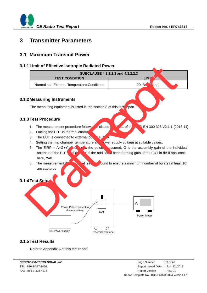
3.1.4 Test Setup
Power Meter
EUT
Power Cable connect to
dummy battery
DC Power supply Thermal Chamber
3.1.5 Test Results
Refer to Appendix A of this test report.
Draft R
eport

SPORTON INTERNATIONAL INC. Page Number : 10 of 46
TEL : 886-3-327-3456 Report Issued Date : Jun. 12, 2017
FAX : 886-3-328-4978 Report Version : Rev. 01
Report Template No.: BU5-ER328 2024 Version 1.1
CE Radio Test Report Report No. : ER741317
3.2 Maximum Equivalent Isotropically Radiated Power (E.I.R.P.) Spectral Density
3.2.1 Limit of Maximum Power Spectral Density
SUBCLAUSE 4.3.2.3.3
TEST CONDITION LIMIT
Normal and Extreme Temperature Conditions 10dBm / MHz
Remark: Maximum spectral power density is not applicable to FHSS system device.
3.2.2 Measuring Instruments
The measuring equipment is listed in the section 8 of this test report.
3.2.3 Test Procedure
1. The measurement procedure follows the clause 5.4.3.2.1 of the ETSI EN 300 328 V2.1.1 (2016-11).
2. These measurements shall only be performed at normal test conditions.
3. The measurement shall be repeated for the equipment being configured to operate at the lowest,
the middle, and the highest frequency of the stated frequency range.
4. The test procedure shall be as follows:
Step 1:
Connect the EUT to the spectrum analyzer and use the following settings:
Start Frequency 2400MHz
Stop Frequency 2483.5MHz
Resolution BW 10kHz
Video BW 30kHz
Sweep Points 8350
Detector RMS
Trace Mode Max Hold
Sweep time 10 sec
Draft R
eport

SPORTON INTERNATIONAL INC. Page Number : 11 of 46
TEL : 886-3-327-3456 Report Issued Date : Jun. 12, 2017
FAX : 886-3-328-4978 Report Version : Rev. 01
Report Template No.: BU5-ER328 2024 Version 1.1
CE Radio Test Report Report No. : ER741317
Step 2:
Add up the values for amplitude (power) for all the samples in the file.
Step 3:
Normalize the individual values for amplitude so that the sum is equal to the RF Output Power
(e.i.r.p.) measured.
Step 4:
Starting from the first sample in the file (lowest frequency), add up the power of the following
samples representing a 1 MHz segment and record the results for power and position (i.e. sample
#1 to #100). This is the Power Spectral Density (e.i.r.p.) for the first 1 MHz segment which shall be
recorded.
Step 5:
Shift the start point of the samples added up in step 4 by 1 sample and repeat the procedure in step
4 (i.e. sample #2 to #101).
Step 6:
Repeat step 5 until the end of the data set and record the radiated Power Spectral Density values for
each of the 1 MHz segments.
From all the recorded results, the highest value is the maximum Power Spectral Density for the EUT.
This value shall be recorded in the test report.
3.2.4 Test Setup
3.2.5 Test Results
Refer to Appendix A of this test report.
Draft R
eport
SPORTON INTERNATIONAL INC. Page Number : 12 of 46
TEL : 886-3-327-3456 Report Issued Date : Jun. 12, 2017
FAX : 886-3-328-4978 Report Version : Rev. 01
Report Template No.: BU5-ER328 2024 Version 1.1
CE Radio Test Report Report No. : ER741317
3.3 Occupied Channel Bandwidth
3.3.1 Limit of Occupied Channel Bandwidth
Occupied Channel Bandwidth fall completely within 2.4 GHz – 2.4835 GHz
3.3.2 Measuring Instruments
The measuring equipment is listed in the section 8 of this test report.
3.3.3 Test Procedure
1. The measurement procedure follows the clause 5.4.7.2.1 of the ETSI EN 300 328 V2.1.1 (2016-11).
2. The measurement shall be performed only on the lowest and the highest frequency within the stated
frequency range.
3. The test procedure shall be as follows:
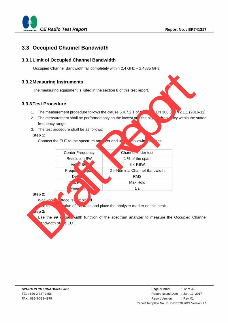
Step 1:
Connect the EUT to the spectrum analyzer and use the following settings:
Center Frequency Channel under test
Resolution BW 1 % of the span
Video BW 3 × RBW
Frequency Span 2 × Nominal Channel Bandwidth
Detector RMS
Trace Mode Max Hold
Sweep Time 1 s
Step 2:
Wait until the trace is completed.
Find the peak value of the trace and place the analyzer marker on this peak.
Step 3:
Use the 99 % bandwidth function of the spectrum analyzer to measure the Occupied Channel
Bandwidth of the EUT.
Draft R
eport
SPORTON INTERNATIONAL INC. Page Number : 13 of 46
TEL : 886-3-327-3456 Report Issued Date : Jun. 12, 2017
FAX : 886-3-328-4978 Report Version : Rev. 01
Report Template No.: BU5-ER328 2024 Version 1.1
CE Radio Test Report Report No. : ER741317
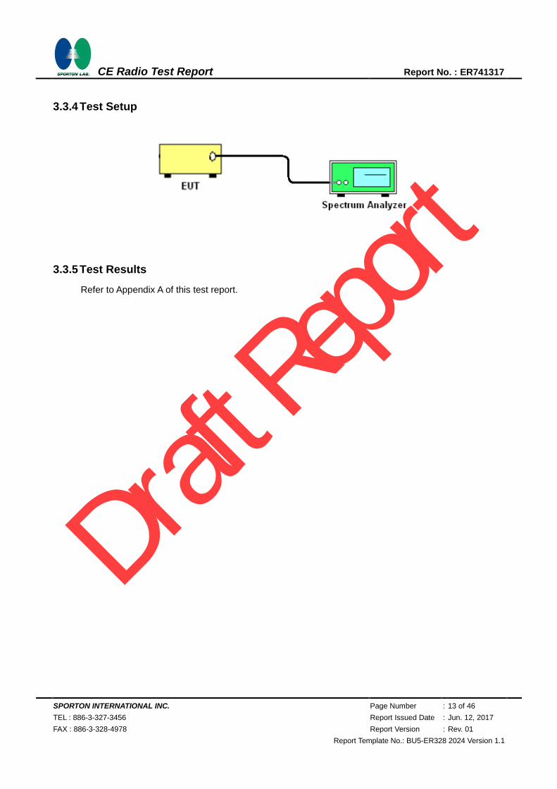
3.3.4 Test Setup
3.3.5 Test Results
Refer to Appendix A of this test report.
Draft R
eport

SPORTON INTERNATIONAL INC. Page Number : 14 of 46
TEL : 886-3-327-3456 Report Issued Date : Jun. 12, 2017
FAX : 886-3-328-4978 Report Version : Rev. 01
Report Template No.: BU5-ER328 2024 Version 1.1
CE Radio Test Report Report No. : ER741317
3.4 Transmitter unwanted emissions in the out-of-band domain
3.4.1 Transmitter unwanted emissions in the out-of-band domain limit
out-of-band domain limit
3.4.2 Measuring Instruments
The measuring equipment is listed in the section 8 of this test report.
3.4.3 Test Procedures
1. The measurement procedure follows the clause 5.4.8.2.1 of the ETSI EN 300 328 V2.1.1
(2016-11).
2. These measurements shall only be performed at normal test conditions.
3. For conducted measurements on devices with multiple transmit chains using the results for each of
the transmit chains for the corresponding 1 MHz segments shall be added and compared with the
transmit mask limit.
3.4.4 Test Setup
3.4.5 Test Results
Refer to Appendix A of this test report.
Draft R
eport
SPORTON INTERNATIONAL INC. Page Number : 15 of 46
TEL : 886-3-327-3456 Report Issued Date : Jun. 12, 2017
FAX : 886-3-328-4978 Report Version : Rev. 01
Report Template No.: BU5-ER328 2024 Version 1.1
CE Radio Test Report Report No. : ER741317
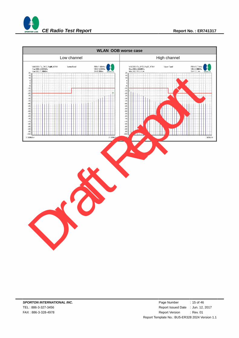
WLAN OOB worse case
Low channel High channel
Draft R
eport

SPORTON INTERNATIONAL INC. Page Number : 16 of 46
TEL : 886-3-327-3456 Report Issued Date : Jun. 12, 2017
FAX : 886-3-328-4978 Report Version : Rev. 01
Report Template No.: BU5-ER328 2024 Version 1.1
CE Radio Test Report Report No. : ER741317
3.5 Transmitter spurious emissions
3.5.1 Limit of Transmitter spurious emissions
In case of equipment with antenna connectors, these limits apply to emissions at the antenna port
(conducted). For emissions radiated by the cabinet or emissions radiated by integral antenna equipment
(without antenna connectors), these limits are e.r.p. for emissions up to 1 GHz and as e.i.r.p. for emissions
above 1 GHz.
SUBCLAUSE 4.3.1.10.3 and 4.3.2.9.3
FREQUENCY RANGE MAXIMUM POWER BANDWIDTH
30 MHz to 47 MHz -36 dBm 100 kHz
47 MHz to 74 MHz -54 dBm 100 kHz
74 MHz to 87,5 MHz -36 dBm 100 kHz
87,5 MHz to 118 MHz -54 dBm 100 kHz
118 MHz to 174 MHz -36 dBm 100 kHz
174 MHz to 230 MHz -54 dBm 100 kHz
230 MHz to 470 MHz -36 dBm 100 kHz
470 MHz to 862 MHz -54 dBm 100 kHz
862 MHz to 1 GHz -36 dBm 100 kHz
1 GHz to 12,75 GHz -30 dBm 1 MHz
3.5.2 Measuring Instruments
The measuring equipment is listed in the section 8 of this test report.
3.5.3 Test Procedures
1. The measurement procedure follows the clause 5.4.9.2.2 of the ETSI EN 300 328 V2.1.1
(2016-11).
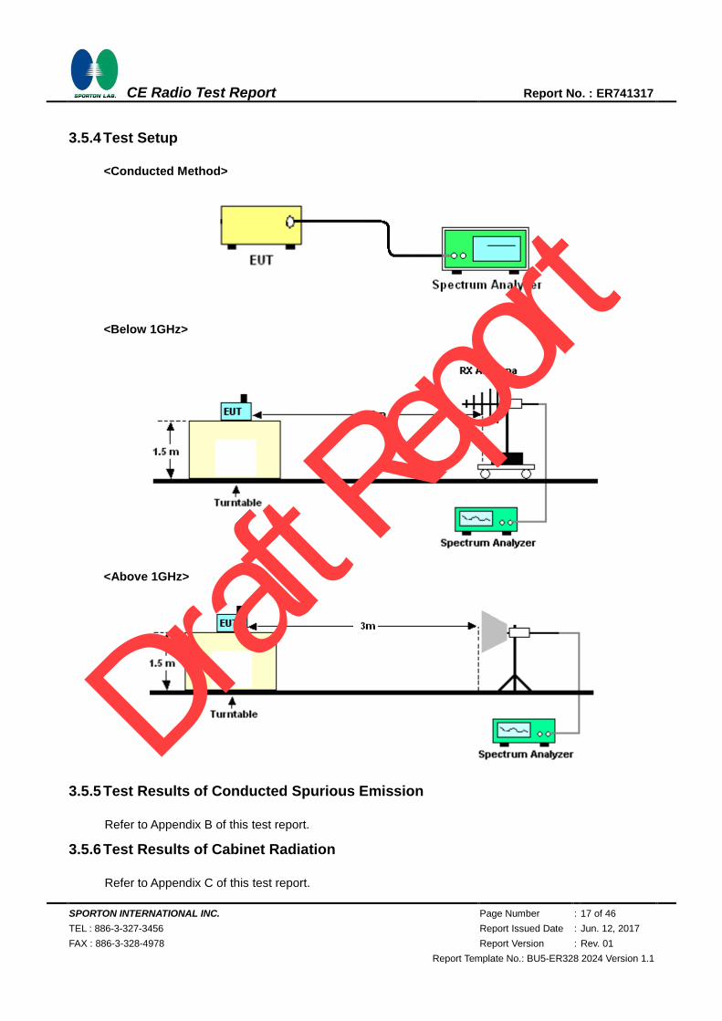
2. The EUT was placed on a turntable with 1.5m height.
3. The test distance between the receiving antenna and the EUT is 3meter below 1GHz frequency
range, and 3 meter which is in far field test condition for measured frequency above 1GHz, while
the receiving (test) antenna is kept at 1.5 meter height.
4. Set EUT in continuous transmitting with maximum output power.
5. The table was rotated from 0 to 360 degree to search the highest radiated emission.
6. Repeating step 3 and 4 for each polarization and channel to find the worst emission level.
7. The results obtained are compared to the limits in order to prove compliance with the requirement.
Draft R
eport
SPORTON INTERNATIONAL INC. Page Number : 17 of 46
TEL : 886-3-327-3456 Report Issued Date : Jun. 12, 2017
FAX : 886-3-328-4978 Report Version : Rev. 01
Report Template No.: BU5-ER328 2024 Version 1.1
CE Radio Test Report Report No. : ER741317
3.5.4 Test Setup
<Conducted Method>
<Below 1GHz>
<Above 1GHz>
3.5.5 Test Results of Conducted Spurious Emission
Refer to Appendix B of this test report.
3.5.6 Test Results of Cabinet Radiation
Refer to Appendix C of this test report.
Draft R
eport
SPORTON INTERNATIONAL INC. Page Number : 18 of 46
TEL : 886-3-327-3456 Report Issued Date : Jun. 12, 2017
FAX : 886-3-328-4978 Report Version : Rev. 01
Report Template No.: BU5-ER328 2024 Version 1.1
CE Radio Test Report Report No. : ER741317
4 Receiver Parameters
4.1 Receiver spurious emissions
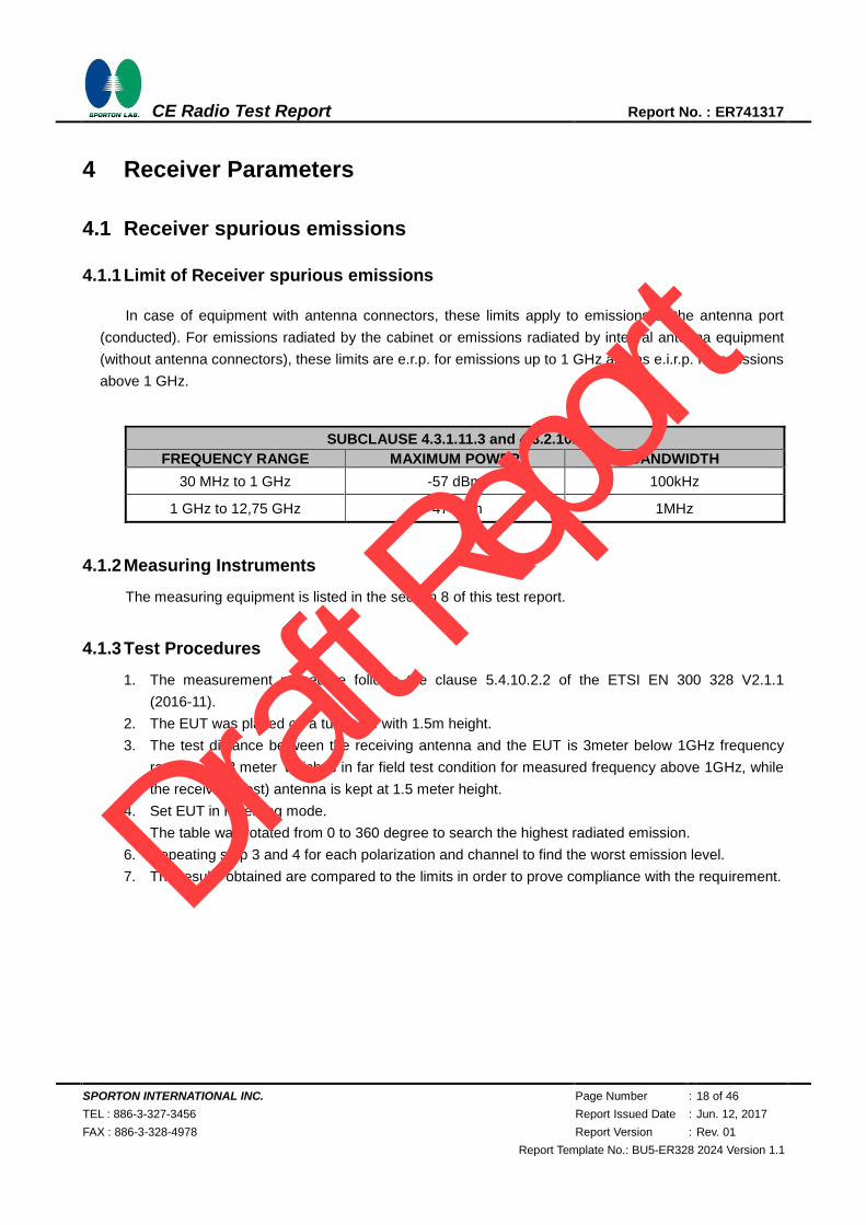
4.1.1 Limit of Receiver spurious emissions
In case of equipment with antenna connectors, these limits apply to emissions at the antenna port
(conducted). For emissions radiated by the cabinet or emissions radiated by integral antenna equipment
(without antenna connectors), these limits are e.r.p. for emissions up to 1 GHz and as e.i.r.p. for emissions
above 1 GHz.
SUBCLAUSE 4.3.1.11.3 and 4.3.2.10.3
FREQUENCY RANGE MAXIMUM POWER BANDWIDTH
30 MHz to 1 GHz -57 dBm 100kHz
1 GHz to 12,75 GHz -47 dBm 1MHz
4.1.2 Measuring Instruments
The measuring equipment is listed in the section 8 of this test report.
4.1.3 Test Procedures
1. The measurement procedure follows the clause 5.4.10.2.2 of the ETSI EN 300 328 V2.1.1
(2016-11).
2. The EUT was placed on a turntable with 1.5m height.
3. The test distance between the receiving antenna and the EUT is 3meter below 1GHz frequency
range, and 3 meter which is in far field test condition for measured frequency above 1GHz, while
the receiving (test) antenna is kept at 1.5 meter height.
4. Set EUT in receiving mode.
5. The table was rotated from 0 to 360 degree to search the highest radiated emission.
6. Repeating step 3 and 4 for each polarization and channel to find the worst emission level.
7. The results obtained are compared to the limits in order to prove compliance with the requirement.
Draft R
eport

SPORTON INTERNATIONAL INC. Page Number : 19 of 46
TEL : 886-3-327-3456 Report Issued Date : Jun. 12, 2017
FAX : 886-3-328-4978 Report Version : Rev. 01
Report Template No.: BU5-ER328 2024 Version 1.1
CE Radio Test Report Report No. : ER741317
4.1.4 Test Setup
<Conducted Method>
<Below 1GHz>
<Above 1GHz>
4.1.5 Test Results of Conducted Spurious Emission
Refer to Appendix B of this test report.
4.1.6 Test Results of Cabinet Radiation
Refer to Appendix C of this test report.
Draft R
eport

SPORTON INTERNATIONAL INC. Page Number : 20 of 46
TEL : 886-3-327-3456 Report Issued Date : Jun. 12, 2017
FAX : 886-3-328-4978 Report Version : Rev. 01
Report Template No.: BU5-ER328 2024 Version 1.1
CE Radio Test Report Report No. : ER741317
4.2 Receiver Blocking Test
4.2.1 Limit of Receiver Blocking Test
Receiver category 1
1. Adaptive equipment with maximum RF output power > 10dBm e.i.r.p. (EX: WiFi)
Receiver category 2
1. Non-adaptive equipment with MU 1% ~ 10%
2. Adaptive equipment with Maximum RF output power < 10dBm e.i.r.p. (EX: Bluetooth)
Draft R
eport
SPORTON INTERNATIONAL INC. Page Number : 21 of 46
TEL : 886-3-327-3456 Report Issued Date : Jun. 12, 2017
FAX : 886-3-328-4978 Report Version : Rev. 01
Report Template No.: BU5-ER328 2024 Version 1.1
CE Radio Test Report Report No. : ER741317
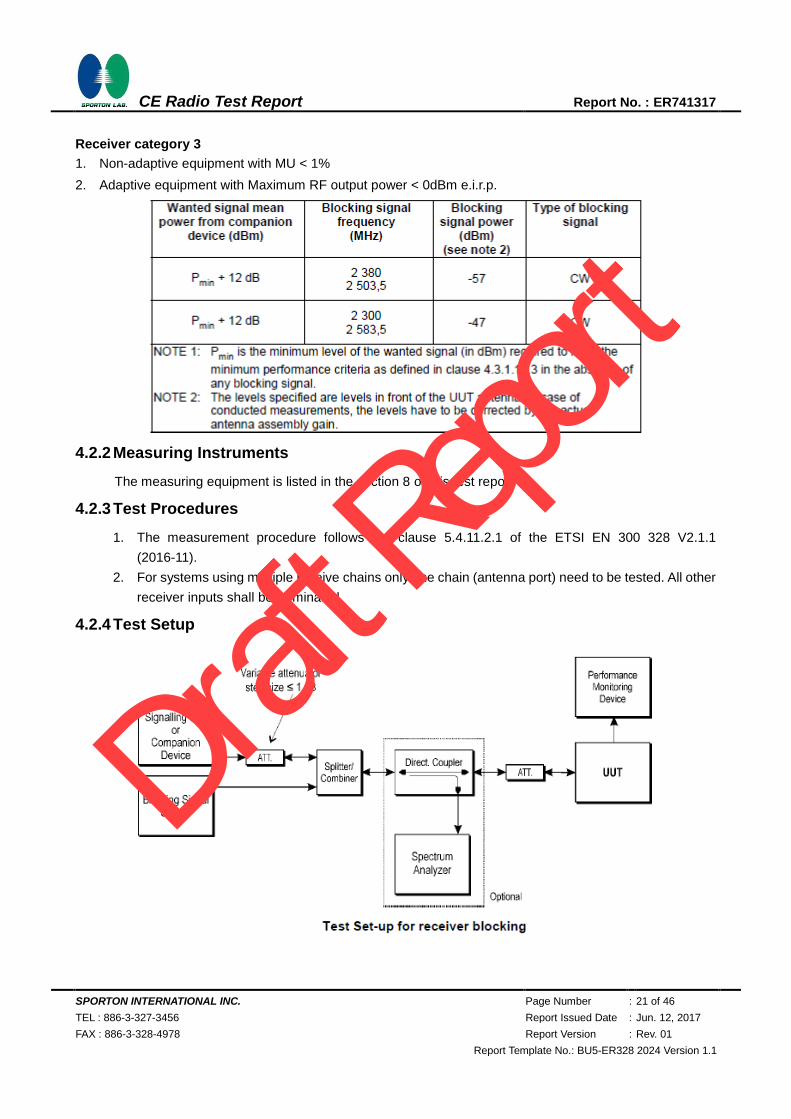
Receiver category 3
1. Non-adaptive equipment with MU < 1%
2. Adaptive equipment with Maximum RF output power < 0dBm e.i.r.p.
4.2.2 Measuring Instruments
The measuring equipment is listed in the section 8 of this test report.
4.2.3 Test Procedures
1. The measurement procedure follows the clause 5.4.11.2.1 of the ETSI EN 300 328 V2.1.1
(2016-11).
2. For systems using multiple receive chains only one chain (antenna port) need to be tested. All other
receiver inputs shall be terminated.
4.2.4 Test Setup
Draft R
eport
SPORTON INTERNATIONAL INC. Page Number : 22 of 46
TEL : 886-3-327-3456 Report Issued Date : Jun. 12, 2017
FAX : 886-3-328-4978 Report Version : Rev. 01
Report Template No.: BU5-ER328 2024 Version 1.1
CE Radio Test Report Report No. : ER741317
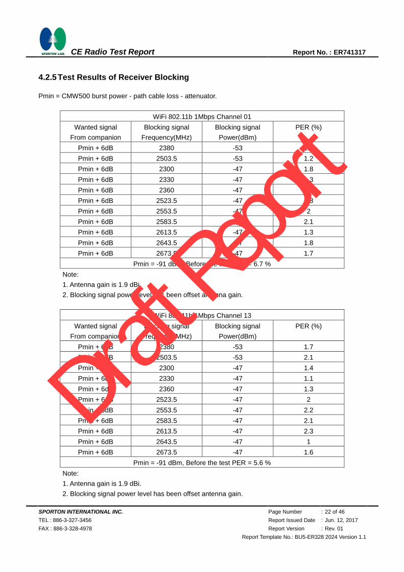
4.2.5 Test Results of Receiver Blocking
Pmin = CMW500 burst power - path cable loss - attenuator.
WiFi 802.11b 1Mbps Channel 01
Wanted signal
From companion
Blocking signal
Frequency(MHz)
Blocking signal
Power(dBm)
PER (%)
Pmin + 6dB 2380 -53 1.9
Pmin + 6dB 2503.5 -53 1.2
Pmin + 6dB 2300 -47 1.8
Pmin + 6dB 2330 -47 1.3
Pmin + 6dB 2360 -47 2.3
Pmin + 6dB 2523.5 -47 1.8
Pmin + 6dB 2553.5 -47 2
Pmin + 6dB 2583.5 -47 2.1
Pmin + 6dB 2613.5 -47 1.3
Pmin + 6dB 2643.5 -47 1.8
Pmin + 6dB 2673.5 -47 1.7
Pmin = -91 dBm, Before the test PER = 6.7 %
Note:
1. Antenna gain is 1.9 dBi.
2. Blocking signal power level has been offset antenna gain.
WiFi 802.11b 1Mbps Channel 13
Wanted signal
From companion
Blocking signal
Frequency(MHz)
Blocking signal
Power(dBm)
PER (%)
Pmin + 6dB 2380 -53 1.7
Pmin + 6dB 2503.5 -53 2.1
Pmin + 6dB 2300 -47 1.4
Pmin + 6dB 2330 -47 1.1
Pmin + 6dB 2360 -47 1.3
Pmin + 6dB 2523.5 -47 2
Pmin + 6dB 2553.5 -47 2.2
Pmin + 6dB 2583.5 -47 2.1
Pmin + 6dB 2613.5 -47 2.3
Pmin + 6dB 2643.5 -47 1
Pmin + 6dB 2673.5 -47 1.6
Pmin = -91 dBm, Before the test PER = 5.6 %
Note:
1. Antenna gain is 1.9 dBi.
2. Blocking signal power level has been offset antenna gain.
Draft R
eport
SPORTON INTERNATIONAL INC. Page Number : 23 of 46
TEL : 886-3-327-3456 Report Issued Date : Jun. 12, 2017
FAX : 886-3-328-4978 Report Version : Rev. 01
Report Template No.: BU5-ER328 2024 Version 1.1
CE Radio Test Report Report No. : ER741317
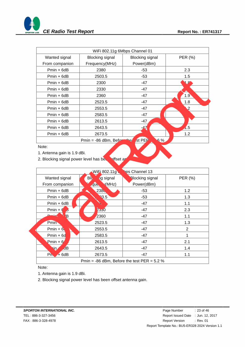
WiFi 802.11g 6Mbps Channel 01
Wanted signal
From companion
Blocking signal
Frequency(MHz)
Blocking signal
Power(dBm)
PER (%)
Pmin + 6dB 2380 -53 2.3
Pmin + 6dB 2503.5 -53 1.5
Pmin + 6dB 2300 -47 1.8
Pmin + 6dB 2330 -47 1.1
Pmin + 6dB 2360 -47 1.9
Pmin + 6dB 2523.5 -47 1.8
Pmin + 6dB 2553.5 -47 1.2
Pmin + 6dB 2583.5 -47 1.5
Pmin + 6dB 2613.5 -47 2
Pmin + 6dB 2643.5 -47 1.5
Pmin + 6dB 2673.5 -47 1.2
Pmin = -86 dBm, Before the test PER = 4.6 %
Note:
1. Antenna gain is 1.9 dBi.
2. Blocking signal power level has been offset antenna gain.
WiFi 802.11g 6Mbps Channel 13
Wanted signal
From companion
Blocking signal
Frequency(MHz)
Blocking signal
Power(dBm)
PER (%)
Pmin + 6dB 2380 -53 1.2
Pmin + 6dB 2503.5 -53 1.3
Pmin + 6dB 2300 -47 1.1
Pmin + 6dB 2330 -47 2.3
Pmin + 6dB 2360 -47 1.1
Pmin + 6dB 2523.5 -47 1.3
Pmin + 6dB 2553.5 -47 2
Pmin + 6dB 2583.5 -47 1
Pmin + 6dB 2613.5 -47 2.1
Pmin + 6dB 2643.5 -47 1.4
Pmin + 6dB 2673.5 -47 1.1
Pmin = -86 dBm, Before the test PER = 5.2 %
Note:
1. Antenna gain is 1.9 dBi.
2. Blocking signal power level has been offset antenna gain.
Draft R
eport

SPORTON INTERNATIONAL INC. Page Number : 24 of 46
TEL : 886-3-327-3456 Report Issued Date : Jun. 12, 2017
FAX : 886-3-328-4978 Report Version : Rev. 01
Report Template No.: BU5-ER328 2024 Version 1.1
CE Radio Test Report Report No. : ER741317
5 Adaptivity Test
5.1 Adaptivity
5.1.1 Limit of Adaptivity
Only for adaptive systems and RF Output Power > 10 dBm
LBT based Detect and Avoid (Load Based Equipment with spectrum sharing mechanism IEEE Std.):
LBT based spectrum sharing mechanism may implement in IEEE Std. 802.11-2012 clauses 9, clause
10, clause 16, clause 17, clause 19 and clause 20, or in IEEE Std. IEEE 802.15.4-2011, clause 4,
clause 5 and clause 8.
Short Control Signaling Transmissions shall have a maximum TxOn / (TxOn + TxOff) ratio of 10 %
within an observation period of 50 ms.
5.1.2 Measurement Instruments
The measuring equipment is listed in the section 8 of this test report.
5.1.3 Test Procedures
1. The measurement procedure follows the clause 5.4.6.2.1 of the ETSI EN 300 328 V2.1.1
(2016-11).
2. For conducted measurements on devices with multiple transmit chains and receive chains. The
power splitter/combiner shall be used to combine all the transmit/receive chains (antenna outputs)
into a single test point. The insertion loss of the power splitter/combiner shall be taken into account.
5.1.4 Test Setup
Draft R
eport
SPORTON INTERNATIONAL INC. Page Number : 25 of 46
TEL : 886-3-327-3456 Report Issued Date : Jun. 12, 2017
FAX : 886-3-328-4978 Report Version : Rev. 01
Report Template No.: BU5-ER328 2024 Version 1.1
CE Radio Test Report Report No. : ER741317
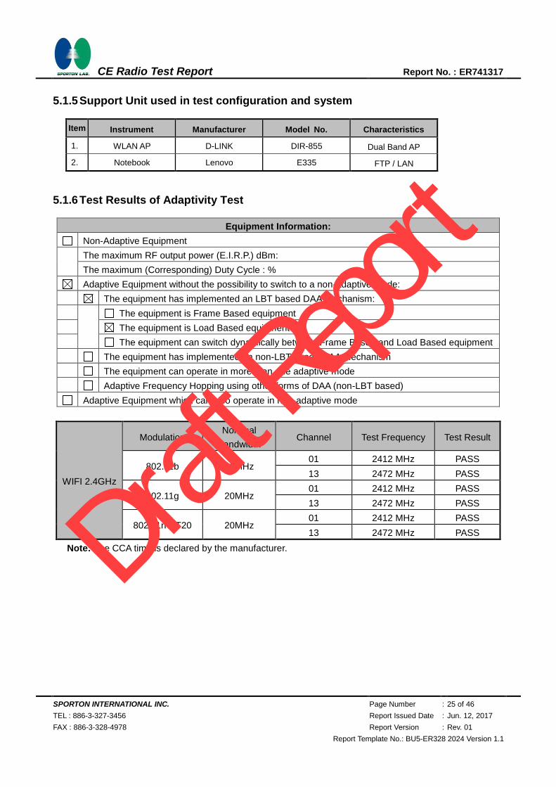
5.1.5 Support Unit used in test configuration and system
Item Instrument Manufacturer Model No. Characteristics
1. WLAN AP D-LINK DIR-855 Dual Band AP
2. Notebook Lenovo E335 FTP / LAN
5.1.6 Test Results of Adaptivity Test
Equipment Information:
Non-Adaptive Equipment
The maximum RF output power (E.I.R.P.) dBm:
The maximum (Corresponding) Duty Cycle : %
Adaptive Equipment without the possibility to switch to a non-adaptive mode:
The equipment has implemented an LBT based DAA mechanism:
The equipment is Frame Based equipment
The equipment is Load Based equipment
The equipment can switch dynamically between Frame Based and Load Based equipment
The equipment has implemented an non-LBT based DAA mechanism
The equipment can operate in more than one adaptive mode
Adaptive Frequency Hopping using other forms of DAA (non-LBT based)
Adaptive Equipment which can also operate in non-adaptive mode
WIFI 2.4GHz
Modulation Nominal
Bandwidth Channel Test Frequency Test Result
802.11b 20MHz 01 2412 MHz PASS
13 2472 MHz PASS
802.11g 20MHz 01 2412 MHz PASS
13 2472 MHz PASS
802.11n HT20 20MHz 01 2412 MHz PASS
13 2472 MHz PASS
Note: The CCA time is declared by the manufacturer.
Draft R
eport

SPORTON INTERNATIONAL INC. Page Number : 26 of 46
TEL : 886-3-327-3456 Report Issued Date : Jun. 12, 2017
FAX : 886-3-328-4978 Report Version : Rev. 01
Report Template No.: BU5-ER328 2024 Version 1.1
CE Radio Test Report Report No. : ER741317
5.1.7 Test Plots of Adaptivity Test
802.11b 2412MHz
Maximum Channel Occupancy Time = 2.191ms
Minimum Idle Period = 429.7μs
Draft R
eport
SPORTON INTERNATIONAL INC. Page Number : 27 of 46
TEL : 886-3-327-3456 Report Issued Date : Jun. 12, 2017
FAX : 886-3-328-4978 Report Version : Rev. 01
Report Template No.: BU5-ER328 2024 Version 1.1
CE Radio Test Report Report No. : ER741317
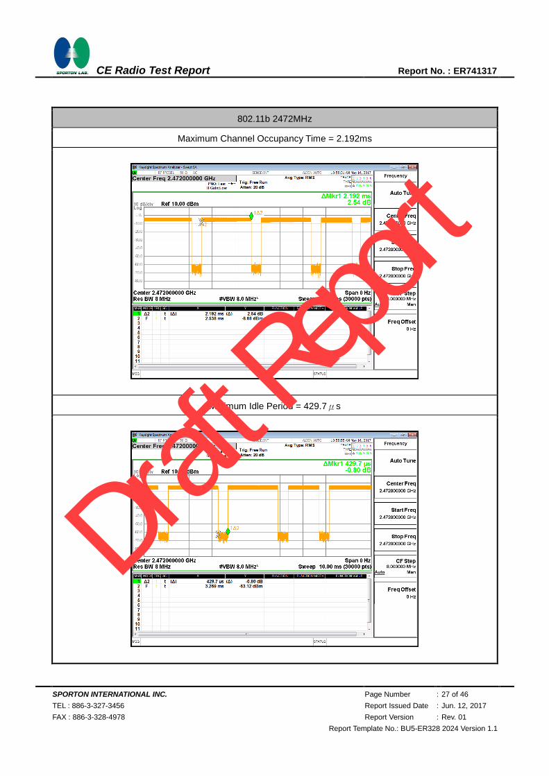
802.11b 2472MHz
Maximum Channel Occupancy Time = 2.192ms
Minimum Idle Period = 429.7μs
Draft R
eport
SPORTON INTERNATIONAL INC. Page Number : 28 of 46
TEL : 886-3-327-3456 Report Issued Date : Jun. 12, 2017
FAX : 886-3-328-4978 Report Version : Rev. 01
Report Template No.: BU5-ER328 2024 Version 1.1
CE Radio Test Report Report No. : ER741317
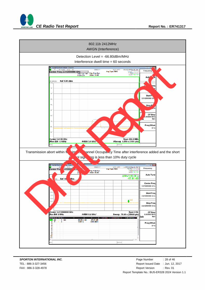
802.11b 2412MHz
AWGN (Interference)
Detection Level = -66.80dBm/MHz
Interference dwell time = 60 seconds
Transmission abort within Maximum Channel Occupancy Time after interference added and the short
control signaling is less than 10% duty cycle
Draft R
eport
SPORTON INTERNATIONAL INC. Page Number : 29 of 46
TEL : 886-3-327-3456 Report Issued Date : Jun. 12, 2017
FAX : 886-3-328-4978 Report Version : Rev. 01
Report Template No.: BU5-ER328 2024 Version 1.1
CE Radio Test Report Report No. : ER741317
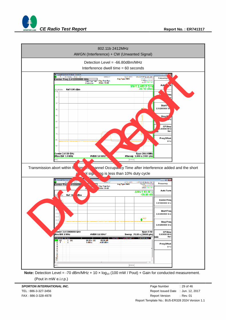
802.11b 2412MHz
AWGN (Interference) + CW (Unwanted Signal)
Detection Level = -66.80dBm/MHz
Interference dwell time = 60 seconds
Transmission abort within Maximum Channel Occupancy Time after interference added and the short
control signaling is less than 10% duty cycle
Note: Detection Level = -70 dBm/MHz + 10 × log10 (100 mW / Pout) + Gain for conducted measurement.
(Pout in mW e.i.r.p.)
Draft R
eport
SPORTON INTERNATIONAL INC. Page Number : 30 of 46
TEL : 886-3-327-3456 Report Issued Date : Jun. 12, 2017
FAX : 886-3-328-4978 Report Version : Rev. 01
Report Template No.: BU5-ER328 2024 Version 1.1
CE Radio Test Report Report No. : ER741317
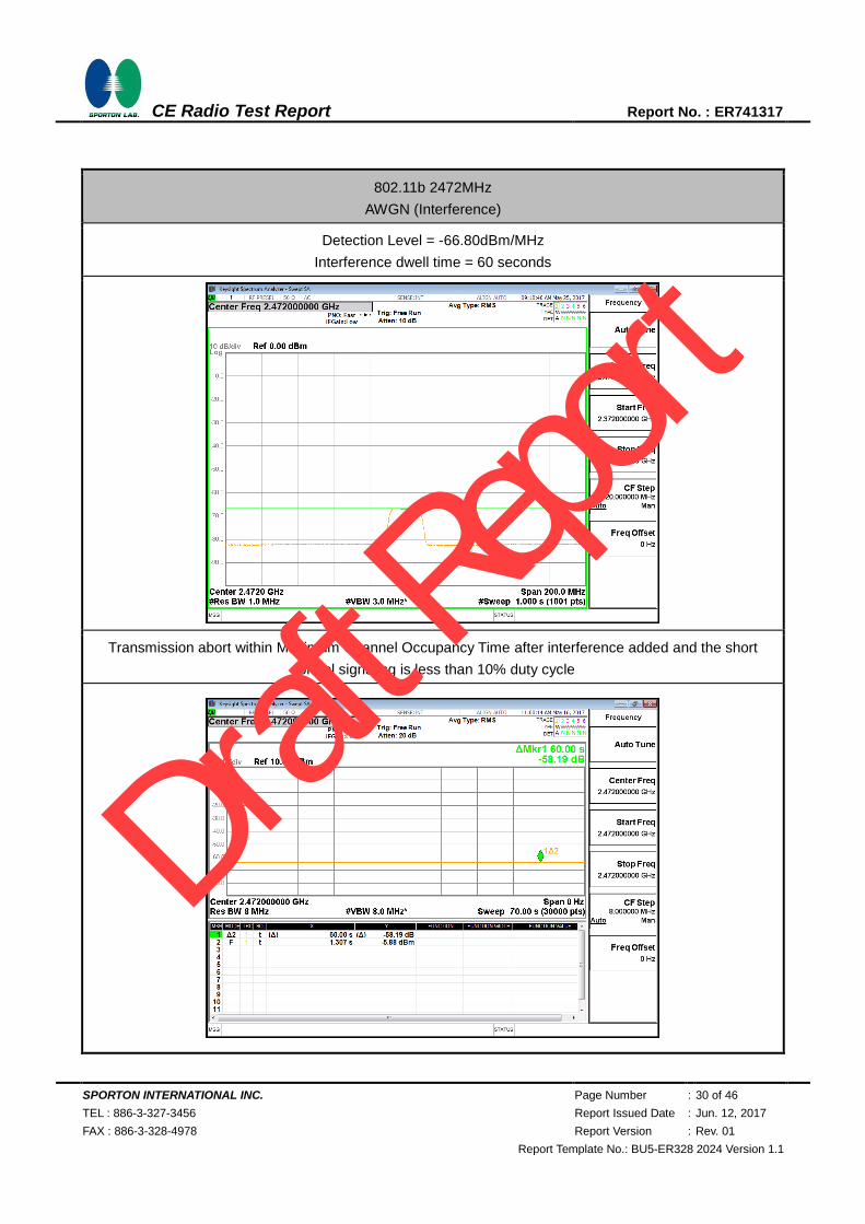
802.11b 2472MHz
AWGN (Interference)
Detection Level = -66.80dBm/MHz
Interference dwell time = 60 seconds
Transmission abort within Maximum Channel Occupancy Time after interference added and the short
control signaling is less than 10% duty cycle
Draft R
eport

SPORTON INTERNATIONAL INC. Page Number : 31 of 46
TEL : 886-3-327-3456 Report Issued Date : Jun. 12, 2017
FAX : 886-3-328-4978 Report Version : Rev. 01
Report Template No.: BU5-ER328 2024 Version 1.1
CE Radio Test Report Report No. : ER741317
802.11b 2472MHz
AWGN (Interference) + CW (Unwanted Signal)
Detection Level = -66.80dBm/MHz
Interference dwell time = 60 seconds
Transmission abort within Maximum Channel Occupancy Time after interference added and the short
control signaling is less than 10% duty cycle
Note: Detection Level = -70 dBm/MHz + 10 × log10 (100 mW / Pout) + Gain for conducted measurement.
(Pout in mW e.i.r.p.)
Draft R
eport

SPORTON INTERNATIONAL INC. Page Number : 32 of 46
TEL : 886-3-327-3456 Report Issued Date : Jun. 12, 2017
FAX : 886-3-328-4978 Report Version : Rev. 01
Report Template No.: BU5-ER328 2024 Version 1.1
CE Radio Test Report Report No. : ER741317
802.11g 2412MHz
Maximum Channel Occupancy Time = 359.3μs
Minimum Idle Period = 181.5μs
Draft R
eport
SPORTON INTERNATIONAL INC. Page Number : 33 of 46
TEL : 886-3-327-3456 Report Issued Date : Jun. 12, 2017
FAX : 886-3-328-4978 Report Version : Rev. 01
Report Template No.: BU5-ER328 2024 Version 1.1
CE Radio Test Report Report No. : ER741317
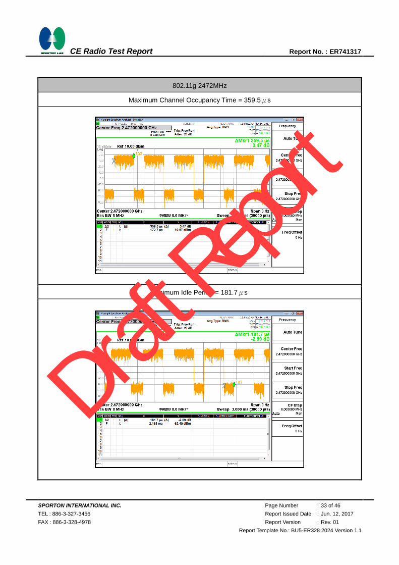
802.11g 2472MHz
Maximum Channel Occupancy Time = 359.5μs
Minimum Idle Period = 181.7μs
Draft R
eport
SPORTON INTERNATIONAL INC. Page Number : 34 of 46
TEL : 886-3-327-3456 Report Issued Date : Jun. 12, 2017
FAX : 886-3-328-4978 Report Version : Rev. 01
Report Template No.: BU5-ER328 2024 Version 1.1
CE Radio Test Report Report No. : ER741317
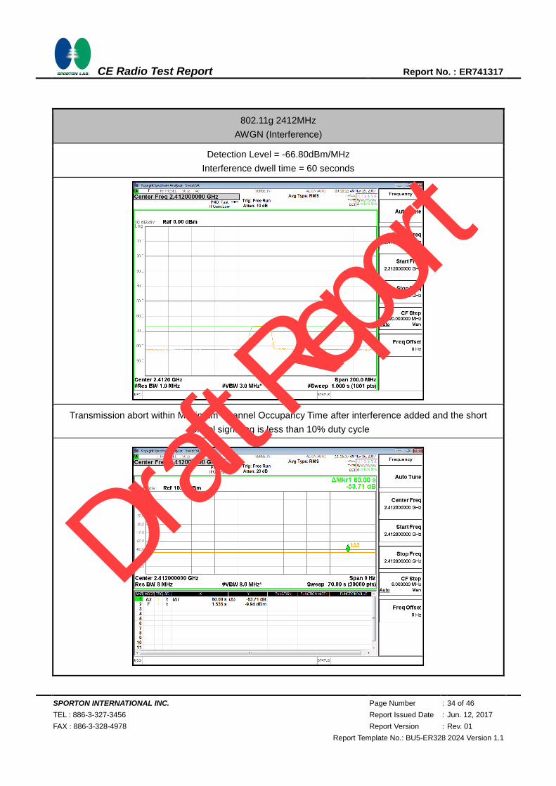
802.11g 2412MHz
AWGN (Interference)
Detection Level = -66.80dBm/MHz
Interference dwell time = 60 seconds
Transmission abort within Maximum Channel Occupancy Time after interference added and the short
control signaling is less than 10% duty cycle
Draft R
eport

SPORTON INTERNATIONAL INC. Page Number : 35 of 46
TEL : 886-3-327-3456 Report Issued Date : Jun. 12, 2017
FAX : 886-3-328-4978 Report Version : Rev. 01
Report Template No.: BU5-ER328 2024 Version 1.1
CE Radio Test Report Report No. : ER741317
802.11g 2412MHz
AWGN (Interference) + CW (Unwanted Signal)
Detection Level = -66.80dBm/MHz
Interference dwell time = 60 seconds
Transmission abort within Maximum Channel Occupancy Time after interference added and the short
control signaling is less than 10% duty cycle
Note: Detection Level = -70 dBm/MHz + 10 × log10 (100 mW / Pout) + Gain for conducted measurement.
(Pout in mW e.i.r.p.)
Draft R
eport

SPORTON INTERNATIONAL INC. Page Number : 36 of 46
TEL : 886-3-327-3456 Report Issued Date : Jun. 12, 2017
FAX : 886-3-328-4978 Report Version : Rev. 01
Report Template No.: BU5-ER328 2024 Version 1.1
CE Radio Test Report Report No. : ER741317
802.11g 2472MHz
AWGN (Interference)
Detection Level = -66.80dBm/MHz
Interference dwell time = 60 seconds
Transmission abort within Maximum Channel Occupancy Time after interference added and the short
control signaling is less than 10% duty cycle
Draft R
eport
SPORTON INTERNATIONAL INC. Page Number : 37 of 46
TEL : 886-3-327-3456 Report Issued Date : Jun. 12, 2017
FAX : 886-3-328-4978 Report Version : Rev. 01
Report Template No.: BU5-ER328 2024 Version 1.1
CE Radio Test Report Report No. : ER741317
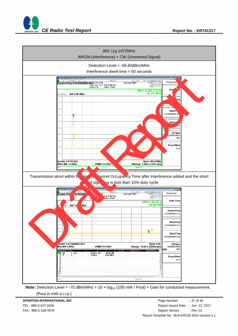
802.11g 2472MHz
AWGN (Interference) + CW (Unwanted Signal)
Detection Level = -66.80dBm/MHz
Interference dwell time = 60 seconds
Transmission abort within Maximum Channel Occupancy Time after interference added and the short
control signaling is less than 10% duty cycle
Note: Detection Level = -70 dBm/MHz + 10 × log10 (100 mW / Pout) + Gain for conducted measurement.
(Pout in mW e.i.r.p.)
Draft R
eport

SPORTON INTERNATIONAL INC. Page Number : 38 of 46
TEL : 886-3-327-3456 Report Issued Date : Jun. 12, 2017
FAX : 886-3-328-4978 Report Version : Rev. 01
Report Template No.: BU5-ER328 2024 Version 1.1
CE Radio Test Report Report No. : ER741317
802.11n HT20 2412MHz
Maximum Channel Occupancy Time = 347.7μs
Minimum Idle Period = 147.8μs
Draft R
eport

SPORTON INTERNATIONAL INC. Page Number : 39 of 46
TEL : 886-3-327-3456 Report Issued Date : Jun. 12, 2017
FAX : 886-3-328-4978 Report Version : Rev. 01
Report Template No.: BU5-ER328 2024 Version 1.1
CE Radio Test Report Report No. : ER741317
802.11n HT20 2472MHz
Maximum Channel Occupancy Time = 347.1μs
Minimum Idle Period = 205.6μs
Draft R
eport

SPORTON INTERNATIONAL INC. Page Number : 40 of 46
TEL : 886-3-327-3456 Report Issued Date : Jun. 12, 2017
FAX : 886-3-328-4978 Report Version : Rev. 01
Report Template No.: BU5-ER328 2024 Version 1.1
CE Radio Test Report Report No. : ER741317
802.11n HT20 2412MHz
AWGN (Interference)
Detection Level = -66.80dBm/MHz
Interference dwell time = 60 seconds
Transmission abort within Maximum Channel Occupancy Time after interference added and the short
control signaling is less than 10% duty cycle
Draft R
eport

SPORTON INTERNATIONAL INC. Page Number : 41 of 46
TEL : 886-3-327-3456 Report Issued Date : Jun. 12, 2017
FAX : 886-3-328-4978 Report Version : Rev. 01
Report Template No.: BU5-ER328 2024 Version 1.1
CE Radio Test Report Report No. : ER741317
802.11n HT20 2412MHz
AWGN (Interference) + CW (Unwanted Signal)
Detection Level = -66.80dBm/MHz
Interference dwell time = 60 seconds
Transmission abort within Maximum Channel Occupancy Time after interference added and the short
control signaling is less than 10% duty cycle
Note: Detection Level = -70 dBm/MHz + 10 × log10 (100 mW / Pout) + Gain for conducted measurement.
(Pout in mW e.i.r.p.)
Draft R
eport
SPORTON INTERNATIONAL INC. Page Number : 42 of 46
TEL : 886-3-327-3456 Report Issued Date : Jun. 12, 2017
FAX : 886-3-328-4978 Report Version : Rev. 01
Report Template No.: BU5-ER328 2024 Version 1.1
CE Radio Test Report Report No. : ER741317
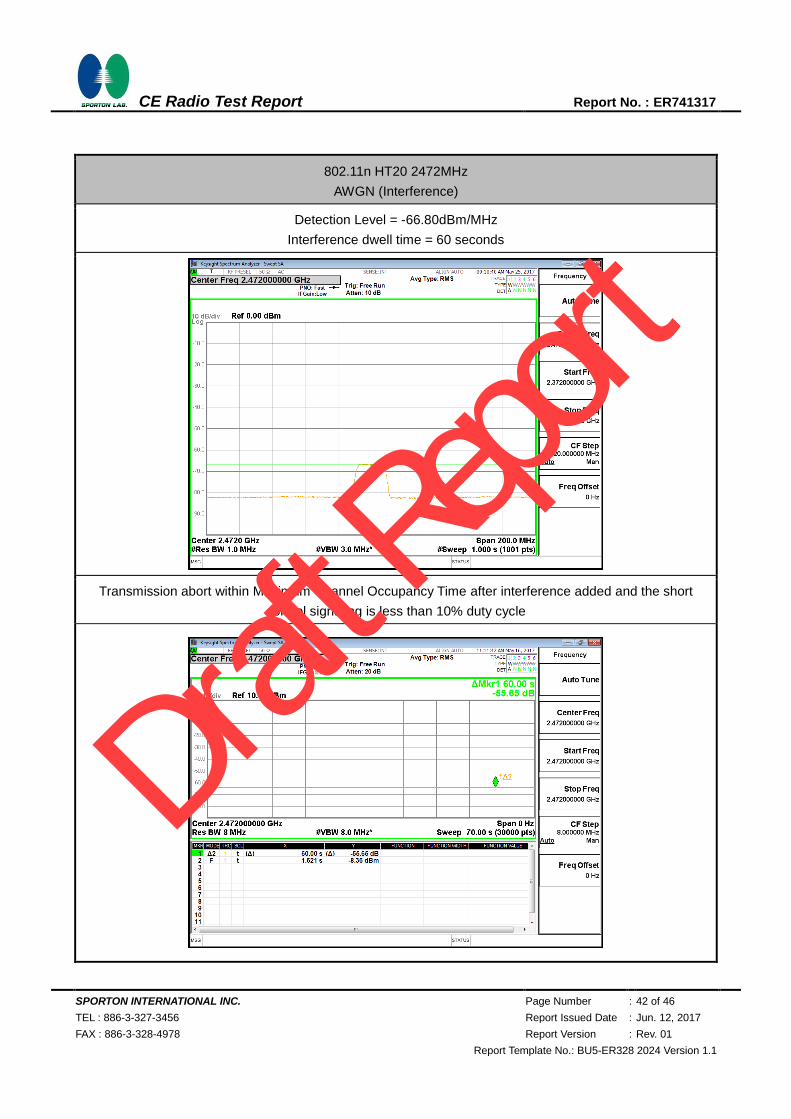
802.11n HT20 2472MHz
AWGN (Interference)
Detection Level = -66.80dBm/MHz
Interference dwell time = 60 seconds
Transmission abort within Maximum Channel Occupancy Time after interference added and the short
control signaling is less than 10% duty cycle
Draft R
eport

SPORTON INTERNATIONAL INC. Page Number : 43 of 46
TEL : 886-3-327-3456 Report Issued Date : Jun. 12, 2017
FAX : 886-3-328-4978 Report Version : Rev. 01
Report Template No.: BU5-ER328 2024 Version 1.1
CE Radio Test Report Report No. : ER741317
802.11n HT20 2472MHz
AWGN (Interference) + CW (Unwanted Signal)
Detection Level = -66.80dBm/MHz
Interference dwell time = 60 seconds
Transmission abort within Maximum Channel Occupancy Time after interference added and the short
control signaling is less than 10% duty cycle
Note: Detection Level = -70 dBm/MHz + 10 × log10 (100 mW / Pout) + Gain for conducted measurement.
(Pout in mW e.i.r.p.)
Draft R
eport

SPORTON INTERNATIONAL INC. Page Number : 44 of 46
TEL : 886-3-327-3456 Report Issued Date : Jun. 12, 2017
FAX : 886-3-328-4978 Report Version : Rev. 01
Report Template No.: BU5-ER328 2024 Version 1.1
CE Radio Test Report Report No. : ER741317
6 Geo-location Capability
6.1 Geo-location
6.1.1 Definition and Requirement
Geo-location capability is a feature of the equipment to determine its geographical location with the
purpose to configure itself according to the regulatory requirements applicable at the geographical
location where it operates.
The geo-location capability may be present in the equipment or in an external device (temporary)
associated with the equipment operating at the same geographical location during the initial power up
of the equipment. The geographical location may also be available in equipment already installed and
operating at the same geographical location.
The geographical location determined by the equipment shall not be accessible to the user.
6.1.2 Description
This device does not support this capability declared by the manufacturer.
Draft R
eport
SPORTON INTERNATIONAL INC. Page Number : 45 of 46
TEL : 886-3-327-3456 Report Issued Date : Jun. 12, 2017
FAX : 886-3-328-4978 Report Version : Rev. 01
Report Template No.: BU5-ER328 2024 Version 1.1
CE Radio Test Report Report No. : ER741317
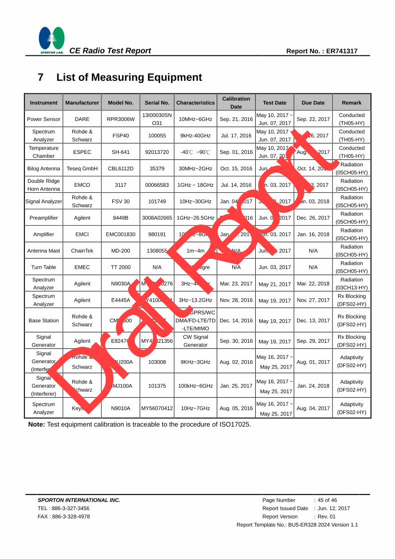
7 List of Measuring Equipment
Instrument Manufacturer Model No. Serial No. Characteristics Calibration
Date Test Date Due Date Remark
Power Sensor DARE RPR3006W 13I00030SN
O31 10MHz~6GHz Sep. 21, 2016
May 10, 2017 ~
Jun. 07, 2017 Sep. 22, 2017
Conducted
(TH05-HY)
Spectrum
Analyzer
Rohde &
Schwarz FSP40 100055 9kHz-40GHz Jul. 17, 2016
May 10, 2017 ~
Jun. 07, 2017 Jul. 16, 2017
Conducted
(TH05-HY)
Temperature
Chamber ESPEC SH-641 92013720 -40℃ ~90℃ Sep. 01, 2016
May 10, 2017 ~
Jun. 07, 2017 Aug. 31, 2017
Conducted
(TH05-HY)
Bilog Antenna Teseq GmbH CBL6112D 35379 30MHz~2GHz Oct. 15, 2016 Jun. 03, 2017 Oct. 14, 2017 Radiation
(05CH05-HY)
Double Ridge
Horn Antenna EMCO 3117 00066583 1GHz ~ 18GHz Jul. 14, 2016 Jun. 03, 2017 Jul. 13, 2017
Radiation
(05CH05-HY)
Signal Analyzer Rohde &
Schwarz FSV 30 101749 10Hz~30GHz Jan. 04, 2017 Jun. 03, 2017 Jan. 03, 2018
Radiation
(05CH05-HY)
Preamplifier Agilent 8449B 3008A02665 1GHz~26.5GHz Dec. 27, 2016 Jun. 03, 2017 Dec. 26, 2017 Radiation
(05CH05-HY)
Amplifier EMCI EMC001830 980191 10MHz~8GHz Jan. 17, 2017 Jun. 03, 2017 Jan. 16, 2018 Radiation
(05CH05-HY)
Antenna Mast ChainTek MD-200 1308055 1m~4m N/A Jun. 03, 2017 N/A Radiation
(05CH05-HY)
Turn Table EMEC TT 2000 N/A 0-360 degre N/A Jun. 03, 2017 N/A Radiation
(05CH05-HY)
Spectrum
Analyzer Agilent N9030A MY52350276 3Hz~44GHz Mar. 23, 2017 May 21, 2017 Mar. 22, 2018
Radiation
(03CH13-HY)
Spectrum
Analyzer Agilent E4445A MY41000161 3Hz~13.2GHz Nov. 28, 2016 May 19, 2017 Nov. 27, 2017
Rx Blocking
(DFS02-HY)
Base Station Rohde &
Schwarz CMW500 132247
GSM/GPRS/WC
DMA/FD-LTE/TD
-LTE/MIMO
Dec. 14, 2016 May 19, 2017 Dec. 13, 2017 Rx Blocking
(DFS02-HY)
Signal
Generator Agilent E8247C MY43321356
CW Signal
Generator Sep. 30, 2016 May 19, 2017 Sep. 29, 2017
Rx Blocking
(DFS02-HY)
Signal
Generator
(Interferer)
Rohde &
Schwarz SMU200A 103008 9KHz~3GHz Aug. 02, 2016
May 16, 2017 ~
May 25, 2017 Aug. 01, 2017
Adaptivity
(DFS02-HY)
Signal
Generator
(Interferer)
Rohde &
Schwarz SMJ100A 101375 100kHz~6GHz Jan. 25, 2017
May 16, 2017 ~
May 25, 2017 Jan. 24, 2018
Adaptivity
(DFS02-HY)
Spectrum
Analyzer Keysight N9010A MY56070412 10Hz~7GHz Aug. 05, 2016
May 16, 2017 ~
May 25, 2017 Aug. 04, 2017
Adaptivity
(DFS02-HY)
Note: Test equipment calibration is traceable to the procedure of ISO17025.
Draft R
eport

SPORTON INTERNATIONAL INC. Page Number : 46 of 46
TEL : 886-3-327-3456 Report Issued Date : Jun. 12, 2017
FAX : 886-3-328-4978 Report Version : Rev. 01
Report Template No.: BU5-ER328 2024 Version 1.1
CE Radio Test Report Report No. : ER741317
8 Uncertainty Evaluation
Test Item Uncertainty
Occupied Channel Bandwidth ± 0.49 %
RF output power, conducted ±0.61 dB
Power density, conducted ±0.60 dB
Radiated emissions ±2.96dB
Conducted Spurious Emission (30MHz~1000MHz) ±4.90dB
Conducted Spurious Emission (1000MHz~18000MHz) ±5.40dB
Temperature ±0.8 °C
Humidity ±3 %
Time ±0.33 %
Draft R
eport

Report Number : ER741317
Test Engineer: Derek Hsu Temperature: 24 °C
Test Date: 2017/5/10~2017/06/07 Relative Humidity: 54~55 %
A-1 of 5
1
1
1
1
1
1
1
1
1
1.90
1.90
1.90
1.90
1.90
1.90
1.90
1.90
1.90
13.20
15.00
13.20
12.20
15.20
13.90
11.50
15.00
13.70
16.80
15.60
13.20
16.50
15.20
14.20
16.00
14.20
14.30
15.80
14.30
11g 6Mbps 1 2412 13.9013.50
16.30
15.10
12.80
16.30
14.90
TEST RESULTS DATA
EIRP Power
Conducted Power (dBm)
Mod.Data
RateNTXChannel
Freq.
(MHz)
25 °C -20 °C 70 °C
Temperature
Nomal
ExtremeTemperature
Low
ExtremeTemperature
HighGain
(dBi)
11b 1Mbps 13 2472
11g 6Mbps 13 2472
11g 6Mbps 7 2442
HT20 MCS0 1 2412
HT20 MCS0 13 2472
HT20 MCS0 7 2442
11b 1Mbps 7 2442
11b 1Mbps 1 2412
Draft R
eport

1
1
1
1
1
1
1
1
1
20 Pass
20
20 Pass
20 Pass
Pass
16.20
17.70
16.20
15.40
18.20
17.00
14.70
15.10
16.90
15.10
14.10
17.10
17.50
15.10
16.10
17.90
EIRP Power (dBm)
Temperature
Nomal
Temperature
Low
TemperatureHigh
Limit
(dBm)Pass/FailMod.
Data
RateNTXChannel
Freq.(MHz)
20 Pass11b 1Mbps 1 2412
11b 1Mbps 13 2472
20 Pass11b 1Mbps 7 2442
16.10
11g 6Mbps 7 2442
20 Pass11g 6Mbps 1 2412 15.80
18.70
HT20 MCS0 1 2412
20 Pass11g 6Mbps 13 2472 15.80
13.40
HT20 MCS0 13 2472
20 PassHT20 MCS0 7 2442 18.20
16.80
16.90
15.60
18.40
17.10
A-2 of 5
Report Number : ER741317
Draft R
eport
Report Number :
1
1
1
1
1
1
1
1
1
HT20 MCS0 1 2412
Pass
11g 6Mbps 13 2472
11g 6Mbps 7 2442
Pass
Pass10
10
6.40
3.94
HT20 MCS0 13 2472
HT20 MCS0 7 2442
Pass
Pass10
10
7.53
6.01
11b 1Mbps 13 2472
11b 1Mbps 7 2442
11b 1Mbps 1 2412 10
10
10
10
10
Pass
Pass
ER741317
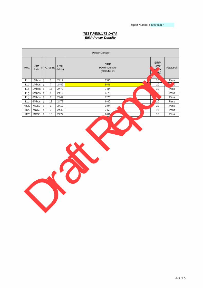
TEST RESULTS DATA
EIRP Power Density
Power Density
Mod.Data
RateNTXChannel
Freq.
(MHz)
EIRP
Limit
(dBm
/MHz)
Pass/Fail
11g 6Mbps 1 2412
Pass
Pass
EIRP
Power Density
(dBm/MHz)
7.85
9.41
7.84
4.76
7.76
A-3 of 5
Draft R
eport

Report Number :
1
1
1
1
1
1
1Mbps 13 2472
Pass2404.92 2419.1214.20
14.28
Pass/Fail
Limit
(Within
operating
Band)
ER741317
TEST RESULTS DATA
99% Occupied Bandwidth
Mod.Data
RateNTXChannel
Freq.
(MHz)
Occupied Bandwidth
99% Occupied BW
(MHz)
Freq. Low
(MHz)
Freq. High
(MHz)
16.84
16.92
17.92
Pass
Pass
Pass
Pass
HT20 MCS0 1 2412
11g 6Mbps 13 2472
2464.92 2479.20
2403.60 2420.44
2463.56 2480.48
2403.04 2420.96
11b
PassHT20 MCS0 13 2472 17.96 2463.04 2481.00
2412
11b 1Mbps 1 2412
11g 6Mbps 1
A-4 of 5
Draft R
eport

Report Number :
1
1
1
1
1
1
ER741317
TEST RESULTS DATA
OOB Emission Level
Mod.Data
RateNTXChannel
Freq.
(MHz)
Limit
(dBm
/MHz)
Pass/FailOOB Emission Worst Level (dBm/MHz)
11b 1Mbps 1 2412
-10,-20 Pass11b 1Mbps 13 2472
-33.36
-33.48
11g 6Mbps 1 2412
-10,-20 Pass11g 6Mbps 13 2472
-19.08
-14.93
HT20 MCS0 13 2472
-10,-20 PassHT20 MCS0 1 2412 -20.32
-16.58 -10,-20 Pass
-10,-20 Pass
-10,-20 Pass
A-5 of 5
Draft R
eport

SPORTON INTERNATIONAL INC.
TEL : 886-3-327-3456 WLAN TX
FAX : 886-3-328-4978 Page Number : 1 of 3
CE Radio Test Report
Report No. : ER741317
Appendix B. Conducted Spurious Emission Plots
WLAN TX Conducted Spurious Emission Plots
Test Engineer : Karl Hou Temperature : 21~22℃
Relative Humidity : 45~46%
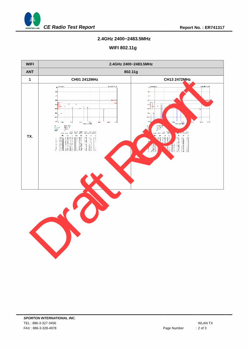
2.4GHz 2400~2483.5MHz
WIFI 802.11b
WIFI 2.4GHz 2400~2483.5MHz
ANT 802.11b
1 CH01 2412MHz CH13 2472MHz
TX
Draft R
eport
SPORTON INTERNATIONAL INC.
TEL : 886-3-327-3456 WLAN TX
FAX : 886-3-328-4978 Page Number : 2 of 3
CE Radio Test Report
Report No. : ER741317
2.4GHz 2400~2483.5MHz
WIFI 802.11g
WIFI 2.4GHz 2400~2483.5MHz
ANT 802.11g
1 CH01 2412MHz CH13 2472MHz
TX.
Draft R
eport

SPORTON INTERNATIONAL INC.
TEL : 886-3-327-3456 WLAN TX
FAX : 886-3-328-4978 Page Number : 3 of 3
CE Radio Test Report
Report No. : ER741317
2.4GHz 2400~2483.5MHz
WIFI 802.11n HT20
WIFI 2.4GHz 2400~2483.5MHz
ANT 802.11n HT20
1 CH01 2412MHz CH13 2472MHz
TX
Draft R
eport

SPORTON INTERNATIONAL INC.
TEL : 886-3-327-3456 WLAN RX
FAX : 886-3-328-4978 Page Number : 1 of 1
CE Radio Test Report
Report No. : ER741317
WLAN RX Conducted Spurious Emission Plots
Test Engineer : Karl Hou Temperature : 21~22℃
Relative Humidity : 45~46%
2.4GHz 2400~2483.5MHz
WIFI 802.11g
WIFI 2.4GHz 2400~2483.5MHz
ANT 802.11g
1 CH13 2472MHz -
TX.
Left blank
Draft R
eport

SPORTON INTERNATIONAL INC.
TEL : 886-3-327-3456 WLAN TX
FAX : 886-3-328-4978 Page Number : 1 of 6
CE Radio Test Report
Report No. : ER741317
Appendix C. Cabinet Radiation Plots
WLAN TX Radiated Spurious Emission Plots
Test Engineer : Karl Hou Temperature : 21~22℃
Relative Humidity : 45~46%
2.4GHz 2400~2483.5MHz
WIFI 802.11b
WIFI 2.4GHz 2400~2483.5MHz
ANT 802.11b CH01 2412MHz
1 Horizontal Vertical
TX
Draft R
eport
SPORTON INTERNATIONAL INC.
TEL : 886-3-327-3456 WLAN TX
FAX : 886-3-328-4978 Page Number : 2 of 6
CE Radio Test Report
Report No. : ER741317
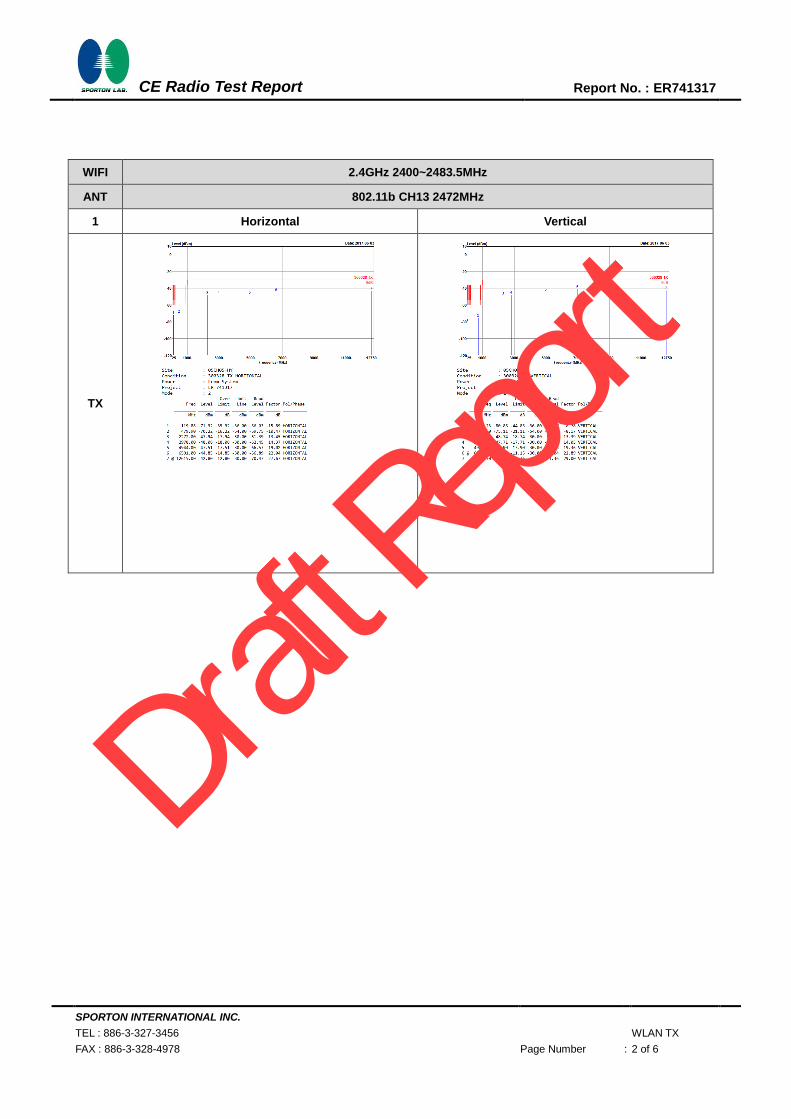
WIFI 2.4GHz 2400~2483.5MHz
ANT 802.11b CH13 2472MHz
1 Horizontal Vertical
TX
Draft R
eport

SPORTON INTERNATIONAL INC.
TEL : 886-3-327-3456 WLAN TX
FAX : 886-3-328-4978 Page Number : 3 of 6
CE Radio Test Report
Report No. : ER741317
2.4GHz 2400~2483.5MHz
WIFI 802.11g
WIFI 2.4GHz 2400~2483.5MHz
ANT 802.11g CH01 2412MHz
1 Horizontal Vertical
TX.
Draft R
eport

SPORTON INTERNATIONAL INC.
TEL : 886-3-327-3456 WLAN TX
FAX : 886-3-328-4978 Page Number : 4 of 6
CE Radio Test Report
Report No. : ER741317
WIFI 2.4GHz 2400~2483.5MHz
ANT 802.11g CH13 2472MHz
1 Horizontal Vertical
TX
Draft R
eport
SPORTON INTERNATIONAL INC.
TEL : 886-3-327-3456 WLAN TX
FAX : 886-3-328-4978 Page Number : 5 of 6
CE Radio Test Report
Report No. : ER741317
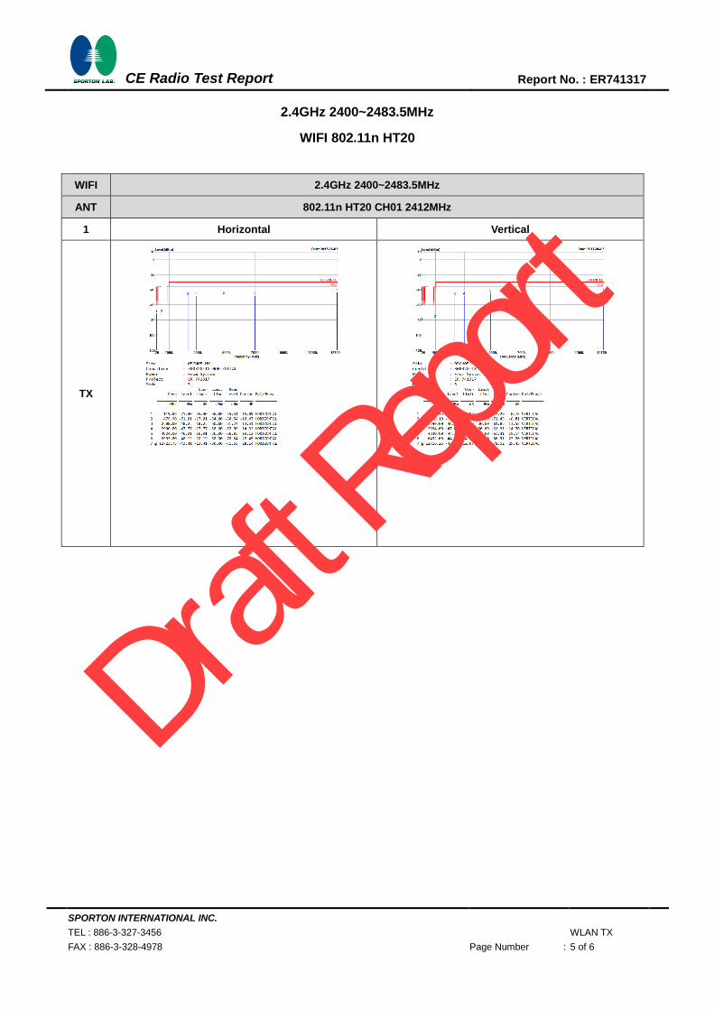
2.4GHz 2400~2483.5MHz
WIFI 802.11n HT20
WIFI 2.4GHz 2400~2483.5MHz
ANT 802.11n HT20 CH01 2412MHz
1 Horizontal Vertical
TX
Draft R
eport

SPORTON INTERNATIONAL INC.
TEL : 886-3-327-3456 WLAN TX
FAX : 886-3-328-4978 Page Number : 6 of 6
CE Radio Test Report
Report No. : ER741317
WIFI 2.4GHz 2400~2483.5MHz
ANT 802.11n HT20 CH13 2472MHz
1 Horizontal Vertical
TX.
Draft R
eport

SPORTON INTERNATIONAL INC.
TEL : 886-3-327-3456 WLAN RX
FAX : 886-3-328-4978 Page Number : 1 of 1
CE Radio Test Report
Report No. : ER741317
WLAN RX Radiated Spurious Emission Plots
Test Engineer : Karl Hou Temperature : 21~22℃
Relative Humidity : 45~46%
2.4GHz 2400~2483.5MHz
WIFI 802.11b
WIFI 2.4GHz 2400~2483.5MHz
ANT 802.11b CH01 2412MHz
1 Horizontal Vertical
RX
Draft R
eport

SPORTON INTERNATIONAL INC. Page Number : D-1 of 2
TEL : 886-3-327-3456
FAX : 886-3-328-4978
CE Radio Test Report Report No. : ER741317
Appendix D. Photographs of Radiated Emission Test Configuration
WLAN Tx/Rx Mode
Remote View
Draft R
eport

SPORTON INTERNATIONAL INC. Page Number : D-2 of 2
TEL : 886-3-327-3456
FAX : 886-3-328-4978
CE Radio Test Report Report No. : ER741317
Near View
Draft R
eport