Embed Size (px)
Citation preview

SPORTON INTERNATIONAL (KUNSHAN) INC. Page Number : 1 of 60
TEL : 86-0512-5790-0158 Report Issued Date : Sep. 16, 2011
FAX : 86-0512-5790-0958 Report Version : Rev. 01
FCC ID : Q78-V71A
FCC RF Test Report Report No. : FR181807A
FCC RF Test Report
APPLICANT : ZTE CORPORATION
EQUIPMENT : Smart Tab 7
BRAND NAME : ZTE
MODEL NAME : Smart Tab 7
FCC ID : Q78-V71A
STANDARD : FCC Part 15 Subpart C §15.247
CLASSIFICATION : Digital Spread Spectrum (DSS)
The product was received on Aug. 18, 2011 and completely tested on Aug. 31, 2011. We,
SPORTON INTERNATIONAL (KUNSHAN) INC., would like to declare that the tested sample
has been evaluated in accordance with the procedures given in ANSI C63.4-2003 and shown
the compliance with the applicable technical standards.
The test results in this report apply exclusively to the tested model / sample. Without written
approval of SPORTON INTERNATIONAL (KUNSHAN) INC., the test report shall not be
reproduced except in full.
Reviewed by:
Jones Tsai / Manager
SPORTON INTERNATIONAL (KUNSHAN) INC. No. 3-2, PingXiang Road, Kunshan, Jiangsu Province, P.R.C.

SPORTON INTERNATIONAL (KUNSHAN) INC. Page Number : 2 of 60
TEL : 86-0512-5790-0158 Report Issued Date : Sep. 16, 2011
FAX : 86-0512-5790-0958 Report Version : Rev. 01
FCC ID : Q78-V71A
FCC RF Test Report Report No. : FR181807A
TABLE OF CONTENTS
REVISION HISTORY .......................................................................................................................................... 3
SUMMARY OF TEST RESULT ......................................................................................................................... 4
1 GENERAL DESCRIPTION .......................................................................................................................... 5
1.1 Applicant ............................................................................................................................................ 5
1.2 Manufacturer ...................................................................................................................................... 5
1.3 Feature of Equipment Under Test ..................................................................................................... 5
1.4 Testing Site ........................................................................................................................................ 6
1.5 Applied Standards ............................................................................................................................. 6
1.6 Ancillary Equipment List .................................................................................................................... 7
2 TEST CONFIGURATION OF EQUIPMENT UNDER TEST ........................................................................ 8
2.1 RF Output Power ............................................................................................................................... 8
2.2 Test Mode .......................................................................................................................................... 9
2.3 Connection Diagram of Test System ............................................................................................... 10
2.4 RF Utility .......................................................................................................................................... 11
3 TEST RESULT .......................................................................................................................................... 12
3.1 Number of Channel Measurement .................................................................................................. 12
3.2 20dB Bandwidth Measurement ....................................................................................................... 14
3.3 Hopping Channel Separation Measurement ................................................................................... 21
3.4 Dwell Time Measurement ................................................................................................................ 24
3.5 Peak Output Power Measurement .................................................................................................. 26
3.6 Band Edges Measurement .............................................................................................................. 29
3.7 Spurious Emission Measurement .................................................................................................... 40
3.8 AC Conducted Emission Measurement........................................................................................... 44
3.9 Radiated Emission Measurement .................................................................................................... 48
3.10 Antenna Requirements .................................................................................................................... 57
4 LIST OF MEASURING EQUIPMENT ........................................................................................................ 58
5 UNCERTAINTY OF EVALUATION ........................................................................................................... 59
APPENDIX A. PHOTOGRAPHS OF EUT
APPENDIX B. SETUP PHOTOGRAPHS

SPORTON INTERNATIONAL (KUNSHAN) INC. Page Number : 3 of 60
TEL : 86-0512-5790-0158 Report Issued Date : Sep. 16, 2011
FAX : 86-0512-5790-0958 Report Version : Rev. 01
FCC ID : Q78-V71A
FCC RF Test Report Report No. : FR181807A
REVISION HISTORY
REPORT NO. VERSION DESCRIPTION ISSUED DATE
FR181807A Rev. 01 Initial issue of report Sep. 16, 2011

SPORTON INTERNATIONAL (KUNSHAN) INC. Page Number : 4 of 60
TEL : 86-0512-5790-0158 Report Issued Date : Sep. 16, 2011
FAX : 86-0512-5790-0958 Report Version : Rev. 01
FCC ID : Q78-V71A
FCC RF Test Report Report No. : FR181807A
SUMMARY OF TEST RESULT
Report
Section FCC Rule Description Limit Result Remark
3.1 15.247(a)(1) Number of Channels ≥ 15Chs Pass -
3.2 15.247(a)(1) 20dB Bandwidth NA Pass -
3.3 15.247(a)(1) Channel Separation ≥ 2/3 of 20dB BW Pass -
3.4 15.247(a)(1) Dwell Time of Each
Channel
≤ 0.4sec in 31.6sec
period Pass -
3.5 15.247(b)(1) Peak Output Power ≤ 125 mW Pass -
3.6 15.247(d) Frequency Band Edges ≤ 20dBc Pass -
3.7 15.247(d) Spurious Emission < 20 dBc Pass -
3.8 15.207 AC Conducted Emission 15.207(a) Pass
Under limit
14.83 dB at
0.25 MHz
3.9 15.247(d) Transmitter Radiated
Emission
15.209(a) &
15.247(d) Pass
Under limit
8.68 dB at
40.8 MHz
3.10 15.203 &
15.247(b) Antenna Requirement N/A Pass -

SPORTON INTERNATIONAL (KUNSHAN) INC. Page Number : 5 of 60
TEL : 86-0512-5790-0158 Report Issued Date : Sep. 16, 2011
FAX : 86-0512-5790-0958 Report Version : Rev. 01
FCC ID : Q78-V71A
FCC RF Test Report Report No. : FR181807A
1 General Description
1.1 Applicant
ZTE CORPORATION
ZTE Plaza, Keji Road South, Hi-Tech, Industrial Park, Nanshan District, Shenzhen, Guangdong,
518057, P.R.China
1.2 Manufacturer
ZTE CORPORATION
ZTE Plaza, Keji Road South, Hi-Tech, Industrial Park, Nanshan District, Shenzhen, Guangdong,
518057, P.R.China
1.3 Feature of Equipment Under Test
Product Feature & Specification
Equipment Smart Tab 7
Brand Name ZTE
Model Name Smart Tab 7
FCC ID Q78-V71A
Tx/Rx Frequency Range 2400 MHz ~ 2483.5 MHz Number of Channels 79 Carrier Frequency of Each Channel 2402+n*1 MHz; n=0~78 Channel Spacing 1 MHz
Maximum Output Power to Antenna Bluetooth (1Mbps) : 3.38 dBm (0.0022 W) Bluetooth EDR (2Mbps) : 3.04 dBm (0.0020 W) Bluetooth EDR (3Mbps) : 3.55 dBm (0.0023 W)
Antenna Type Fixed Internal Antenna with gain 0 dBi
HW Version N/A SW Version N/A
Type of Modulation Bluetooth (1Mbps) : GFSK Bluetooth EDR (2Mbps) : π/4-DQPSK Bluetooth EDR (3Mbps) : 8-DPSK
EUT Stage Identical Prototype
Remark:
1. For other wireless features of this EUT, test report will be issued separately.
2. This test report recorded only product characteristics and test results of Digital Spread Spectrum
(DSS).
3. The above EUT's information was declared by manufacturer. Please refer to the specifications or
user's manual for more detailed description.

SPORTON INTERNATIONAL (KUNSHAN) INC. Page Number : 6 of 60
TEL : 86-0512-5790-0158 Report Issued Date : Sep. 16, 2011
FAX : 86-0512-5790-0958 Report Version : Rev. 01
FCC ID : Q78-V71A
FCC RF Test Report Report No. : FR181807A
1.4 Testing Site
Test Site SPORTON INTERNATIONAL (KUNSHAN) INC.
Test Site
Location
No. 3-2, PingXiang Road, Kunshan, Jiangsu Province, P.R.C.
TEL: +86-0512-5790-0158
FAX: +86-0512-5790-0958
Test Site No. Sporton Site No.
TH01-KS CO01-KS 03CH01-KS
1.5 Applied Standards
According to the specifications of the manufacturer, the EUT must comply with the requirements of the
following standards:
FCC Part 15 Subpart C §15.247
FCC Public Notice DA 00-705
ANSI C63.4-2003
Remark:
1. All test items were verified and recorded according to the standards and without any deviation
during the test.
2. This EUT has also been tested and complied with the requirements of FCC Part 15, Subpart B
(Certification), recorded in a separate test report.

SPORTON INTERNATIONAL (KUNSHAN) INC. Page Number : 7 of 60
TEL : 86-0512-5790-0158 Report Issued Date : Sep. 16, 2011
FAX : 86-0512-5790-0958 Report Version : Rev. 01
FCC ID : Q78-V71A
FCC RF Test Report Report No. : FR181807A
1.6 Ancillary Equipment List
Item Equipment Trade Name Model Name FCC ID Data Cable Power Cord
1. System Simulator R&S CMU 200 N/A N/A Unshielded, 1.8 m
2. Bluetooth
Base Station R&S CBT FCC DoC N/A Unshielded, 1.8 m
3. GPS Station T&E GS-50 N/A N/A Unshielded, 1.8 m
4. Bluetooth
Earphone Nokia BH-102 PYAHS-107W N/A N/A
5. Router D-Link DIR-855 KA2DIR855A2 N/A Unshielded, 1.8 m
6. Notebook DELL P08S QDS-BRCM1030 N/A
AC I/P:
Unshielded, 1.2 m
DC O/P:
Shielded, 1.8 m

SPORTON INTERNATIONAL (KUNSHAN) INC. Page Number : 8 of 60
TEL : 86-0512-5790-0158 Report Issued Date : Sep. 16, 2011
FAX : 86-0512-5790-0958 Report Version : Rev. 01
FCC ID : Q78-V71A
FCC RF Test Report Report No. : FR181807A
2 Test Configuration of Equipment Under Test
2.1 RF Output Power
Preliminary tests were performed in different data rate and recorded the RF output power in the
following table:
Channel Frequency
Bluetooth RF Output Power
Data Rate / Modulation
GFSK π/4-DQPSK 8-DPSK
1Mbps 2Mbps 3Mbps
Ch00 2402MHz 3.38 dBm 3.04 dBm 3.55 dBm
Ch39 2441MHz 3.37 dBm 2.97 dBm 3.54 dBm
Ch78 2480MHz 2.63 dBm 2.32 dBm 2.89 dBm
Remark:
1. The data rate was set in 3Mbps for all the test items due to the highest RF output power.
2. The EUT is programmed to transmit signals continuously for all testing.

SPORTON INTERNATIONAL (KUNSHAN) INC. Page Number : 9 of 60
TEL : 86-0512-5790-0158 Report Issued Date : Sep. 16, 2011
FAX : 86-0512-5790-0958 Report Version : Rev. 01
FCC ID : Q78-V71A
FCC RF Test Report Report No. : FR181807A
2.2 Test Mode
The EUT has been associated with peripherals pursuant to ANSI C63.4-2003 and configuration
operated in a manner tended to maximize its emission characteristics in a typical application.
Frequency range investigated: conduction (150 kHz to 30 MHz), radiation (9 kHz to the 10th harmonic
of the highest fundamental frequency or to 40 GHz, whichever is lower).
Pre-scanned tests, X, Y, Z in three orthogonal panels, were conducted to determine the final
configuration from all possible combinations, laptop / tablet modes.
The following tables are showing the test modes as the worst cases (E2 plane) and recorded in this
report.
Test Cases
Test Item
Data Rate / Modulation
Bluetooth 1Mbps
GFSK
Bluetooth EDR 2Mbps
π/4-DQPSK
Bluetooth EDR 3Mbps
8-DPSK
Conducted
TCs
Mode 1: CH00_2402 MHz
Mode 2: CH39_2441 MHz
Mode 3: CH78_2480 MHz
Mode 4: CH00_2402 MHz
Mode 5: CH39_2441 MHz
Mode 6: CH78_2480 MHz
Mode 7: CH00_2402 MHz
Mode 8: CH39_2441 MHz
Mode 9: CH78_2480 MHz
Radiated
TCs N/A N/A
Mode 1: CH00_2402 MHz
Mode 2: CH39_2441 MHz
Mode 3: CH78_2480 MHz
AC
Conducted
Emission
Mode 1 : GSM 850 Idle + Bluetooth Link + WLAN Link + Adapter + Camera + GPS
Rx
Remark:
1. For radiated TCs, the data rate was set in 3Mbps due to the highest RF output power; only the
data of these modes was reported.

SPORTON INTERNATIONAL (KUNSHAN) INC. Page Number : 10 of 60
TEL : 86-0512-5790-0158 Report Issued Date : Sep. 16, 2011
FAX : 86-0512-5790-0958 Report Version : Rev. 01
FCC ID : Q78-V71A
FCC RF Test Report Report No. : FR181807A
2.3 Connection Diagram of Test System
<Bluetooth Tx Mode>
<AC Conducted Emission Mode>

SPORTON INTERNATIONAL (KUNSHAN) INC. Page Number : 11 of 60
TEL : 86-0512-5790-0158 Report Issued Date : Sep. 16, 2011
FAX : 86-0512-5790-0958 Report Version : Rev. 01
FCC ID : Q78-V71A
FCC RF Test Report Report No. : FR181807A
2.4 RF Utility
For Bluetooth function, key in, “*#3646633” was installed in EUT which was programmed in order to
make the EUT into the engineering modes to contact with Bluetooth base station for transmitting and
receiving signals continuously.

SPORTON INTERNATIONAL (KUNSHAN) INC. Page Number : 12 of 60
TEL : 86-0512-5790-0158 Report Issued Date : Sep. 16, 2011
FAX : 86-0512-5790-0958 Report Version : Rev. 01
FCC ID : Q78-V71A
FCC RF Test Report Report No. : FR181807A
3 Test Result
3.1 Number of Channel Measurement
3.1.1 Limits of Number of Hopping Frequency
Frequency hopping systems in the 2400-2483.5 MHz band shall use at least 15 channels.
3.1.2 Measuring Instruments
See list of measuring instruments of this test report.
3.1.3 Test Procedure
1. The testing follows FCC Public Notice DA 00-705 Measurement Guidelines.
2. The RF output of EUT was connected to the spectrum analyzer by a low loss cable.
3. The modulation types of EUT are irrelevant to number of hopping channels deviation.
4. The EUT must have its hopping function enabled. Use the following spectrum analyzer settings:
Span = the frequency band of operation; RBW 1% of the span; VBW RBW; Sweep = auto;
Detector function = peak; Trace = max hold.
5. The number of hopping frequency used is defined as the device has the numbers of total
channel.
3.1.4 Test Setup

SPORTON INTERNATIONAL (KUNSHAN) INC. Page Number : 13 of 60
TEL : 86-0512-5790-0158 Report Issued Date : Sep. 16, 2011
FAX : 86-0512-5790-0958 Report Version : Rev. 01
FCC ID : Q78-V71A
FCC RF Test Report Report No. : FR181807A
3.1.5 Test Result of Number of Hopping Frequency
Test Mode : Mode 7~9 Temperature : 23~24℃
Test Engineer : Jun Liu Relative Humidity : 45~47%
Number of Hopping Channels
(Channel)
Limits
(Channel) Pass/Fail
79 > 15 Pass
Number of Hopping Channel Plot on Channel 00 - 78
A
Offset 14.8 dB
LVL
Ref 20 dBm Att 20 dB **
4.1 MHz/Start 2.4 GHz Stop 2.441 GHz
*
*
RBW 1 MHz
VBW 1 MHz
SWT 500 ms*
1 PKMAXH
-80
-70
-60
-50
-40
-30
-20
-10
0
10
20
Date: 30.AUG.2011 00:07:08
Ref 20 dBm Att 20 dB **
*
Offset 14.8 dB
A
LVL
RBW 1 MHz
VBW 1 MHz
SWT 500 ms
*
Start 2.441 GHz Stop 2.4835 GHz4.25 MHz/
*
1 PKMAXH
-80
-70
-60
-50
-40
-30
-20
-10
0
10
20
Date: 30.AUG.2011 00:11:40

SPORTON INTERNATIONAL (KUNSHAN) INC. Page Number : 14 of 60
TEL : 86-0512-5790-0158 Report Issued Date : Sep. 16, 2011
FAX : 86-0512-5790-0958 Report Version : Rev. 01
FCC ID : Q78-V71A
FCC RF Test Report Report No. : FR181807A
3.2 20dB Bandwidth Measurement
3.2.1 Limit of 20dB Bandwidth
N/A
3.2.2 Measuring Instruments
See list of measuring instruments of this test report.
3.2.3 Test Procedures
1. The testing follows FCC Public Notice DA 00-705 Measurement Guidelines.
2. The RF output of EUT was connected to the spectrum analyzer by a low loss cable.
3. The EUT should be transmitting at its maximum data rate as the worst cases.
4. Use the following spectrum analyzer settings:
Span = approximately 2 to 3 times the 20 dB bandwidth, centered on a hopping channel;
RBW 1% of the 20 dB bandwidth; VBW RBW; Sweep = auto; Detector function = peak;
Trace = max hold.
5. The marker-delta reading at this point is the 20 dB bandwidth of the emission.
3.2.4 Test Setup

SPORTON INTERNATIONAL (KUNSHAN) INC. Page Number : 15 of 60
TEL : 86-0512-5790-0158 Report Issued Date : Sep. 16, 2011
FAX : 86-0512-5790-0958 Report Version : Rev. 01
FCC ID : Q78-V71A
FCC RF Test Report Report No. : FR181807A
3.2.5 Test Result of 20dB Bandwidth
Test Mode : Mode 1, 2, 3 Temperature : 23~24℃
Test Engineer : Jun Liu Relative Humidity : 45~47%
Channel Frequency (MHz) 20dB Bandwidth (MHz)
00 2402 0.916
39 2441 0.916
78 2480 0.904
20 dB Bandwidth Plot on Channel 00
A
Offset 14.8 dB
LVL
Ref 20 dBm
Center 2.402 GHz Span 2 MHz200 kHz/
Att 20 dB*
RBW 30 kHz
SWT 2.5 ms
*
VBW 300 kHz*
1 PKMAXH
-80
-70
-60
-50
-40
-30
-20
-10
0
10
20
1
Marker 1 [T1 ]
0.42 dBm
2.401996000 GHz
ndB [T1] 20.00 dB
BW 916.000000000 kHz
T1
Temp 1 [T1 ndB]
-19.73 dBm
2.401556000 GHz
T2
Temp 2 [T1 ndB]
-19.50 dBm
2.402472000 GHz
Date: 29.AUG.2011 23:56:57

SPORTON INTERNATIONAL (KUNSHAN) INC. Page Number : 16 of 60
TEL : 86-0512-5790-0158 Report Issued Date : Sep. 16, 2011
FAX : 86-0512-5790-0958 Report Version : Rev. 01
FCC ID : Q78-V71A
FCC RF Test Report Report No. : FR181807A
20 dB Bandwidth Plot on Channel 39
20 dB Bandwidth Plot on Channel 78
A
Offset 14.8 dB
LVL
Ref 20 dBm
Center 2.441 GHz Span 2 MHz200 kHz/
Att 20 dB*
RBW 30 kHz
SWT 2.5 ms
*
VBW 300 kHz*
1 PKMAXH
-80
-70
-60
-50
-40
-30
-20
-10
0
10
20
1
Marker 1 [T1 ]
0.45 dBm
2.440988000 GHz
ndB [T1] 20.00 dB
BW 916.000000000 kHz
T1
Temp 1 [T1 ndB]
-19.78 dBm
2.440548000 GHz
T2
Temp 2 [T1 ndB]
-19.60 dBm
2.441464000 GHz
Date: 29.AUG.2011 23:57:23
A
Offset 14.8 dB
LVL
Ref 20 dBm
Center 2.48 GHz Span 2 MHz200 kHz/
Att 20 dB*
RBW 30 kHz
SWT 2.5 ms
*
VBW 300 kHz*
1 PKMAXH
-80
-70
-60
-50
-40
-30
-20
-10
0
10
20
1
Marker 1 [T1 ]
-0.22 dBm
2.479980000 GHz
ndB [T1] 20.00 dB
BW 904.000000000 kHz
T1
Temp 1 [T1 ndB]
-20.63 dBm
2.479544000 GHz
T2
Temp 2 [T1 ndB]
-20.14 dBm
2.480448000 GHz
Date: 29.AUG.2011 23:57:54

SPORTON INTERNATIONAL (KUNSHAN) INC. Page Number : 17 of 60
TEL : 86-0512-5790-0158 Report Issued Date : Sep. 16, 2011
FAX : 86-0512-5790-0958 Report Version : Rev. 01
FCC ID : Q78-V71A
FCC RF Test Report Report No. : FR181807A
Test Mode : Mode 4, 5, 6 Temperature : 23~24℃
Test Engineer : Jun Liu Relative Humidity : 45~47%
Channel Frequency (MHz) 20dB Bandwidth (MHz)
00 2402 1.350
39 2441 1.350
78 2480 1.350
20 dB Bandwidth Plot on Channel 00
A
Offset 14.8 dB
LVL
Ref 20 dBm
Center 2.402 GHz Span 3 MHz300 kHz/
Att 20 dB*
RBW 30 kHz
SWT 5 ms
*
VBW 300 kHz*
1 PKMAXH
-80
-70
-60
-50
-40
-30
-20
-10
0
10
20
1
Marker 1 [T1 ]
-2.15 dBm
2.402000000 GHz
ndB [T1] 20.00 dB
BW 1.350000000 MHz
T1
Temp 1 [T1 ndB]
-22.30 dBm
2.401334000 GHz
T2
Temp 2 [T1 ndB]
-21.98 dBm
2.402684000 GHz
Date: 29.AUG.2011 23:58:38

SPORTON INTERNATIONAL (KUNSHAN) INC. Page Number : 18 of 60
TEL : 86-0512-5790-0158 Report Issued Date : Sep. 16, 2011
FAX : 86-0512-5790-0958 Report Version : Rev. 01
FCC ID : Q78-V71A
FCC RF Test Report Report No. : FR181807A
20 dB Bandwidth Plot on Channel 39
20 dB Bandwidth Plot on Channel 78
A
Offset 14.8 dB
LVL
Ref 20 dBm
Center 2.441 GHz Span 3 MHz300 kHz/
Att 20 dB*
RBW 30 kHz
SWT 5 ms
*
VBW 300 kHz*
1 PKMAXH
-80
-70
-60
-50
-40
-30
-20
-10
0
10
20
1
Marker 1 [T1 ]
-2.30 dBm
2.440988000 GHz
ndB [T1] 20.00 dB
BW 1.350000000 MHz
T1
Temp 1 [T1 ndB]
-22.10 dBm
2.440328000 GHz
T2
Temp 2 [T1 ndB]
-22.39 dBm
2.441678000 GHz
Date: 29.AUG.2011 23:58:56
A
Offset 14.8 dB
LVL
Ref 20 dBm
Center 2.48 GHz Span 3 MHz300 kHz/
Att 20 dB*
RBW 30 kHz
SWT 5 ms
*
VBW 300 kHz*
1 PKMAXH
-80
-70
-60
-50
-40
-30
-20
-10
0
10
20
1
Marker 1 [T1 ]
-3.01 dBm
2.479988000 GHz
ndB [T1] 20.00 dB
BW 1.350000000 MHz
T1
Temp 1 [T1 ndB]
-22.53 dBm
2.479322000 GHz
T2
Temp 2 [T1 ndB]
-23.19 dBm
2.480672000 GHz
Date: 29.AUG.2011 23:59:14

SPORTON INTERNATIONAL (KUNSHAN) INC. Page Number : 19 of 60
TEL : 86-0512-5790-0158 Report Issued Date : Sep. 16, 2011
FAX : 86-0512-5790-0958 Report Version : Rev. 01
FCC ID : Q78-V71A
FCC RF Test Report Report No. : FR181807A
Test Mode : Mode 7, 8, 9 Temperature : 23~24℃
Test Engineer : Jun Liu Relative Humidity : 45~47%
Channel Frequency (MHz) 20dB Bandwidth (MHz)
00 2402 1.344
39 2441 1.344
78 2480 1.338
20 dB Bandwidth Plot on Channel 00
A
Offset 14.8 dB
LVL
Ref 20 dBm
Center 2.402 GHz Span 3 MHz300 kHz/
Att 20 dB*
RBW 30 kHz
SWT 5 ms
*
VBW 300 kHz*
1 PKMAXH
-80
-70
-60
-50
-40
-30
-20
-10
0
10
20
1
Marker 1 [T1 ]
-2.31 dBm
2.401994000 GHz
ndB [T1] 20.00 dB
BW 1.344000000 MHz
T1
Temp 1 [T1 ndB]
-22.73 dBm
2.401334000 GHz
T2
Temp 2 [T1 ndB]
-22.99 dBm
2.402678000 GHz
Date: 29.AUG.2011 23:46:01

SPORTON INTERNATIONAL (KUNSHAN) INC. Page Number : 20 of 60
TEL : 86-0512-5790-0158 Report Issued Date : Sep. 16, 2011
FAX : 86-0512-5790-0958 Report Version : Rev. 01
FCC ID : Q78-V71A
FCC RF Test Report Report No. : FR181807A
20 dB Bandwidth Plot on Channel 39
20 dB Bandwidth Plot on Channel 78
A
Offset 14.8 dB
LVL
Ref 20 dBm
Center 2.441 GHz Span 3 MHz300 kHz/
Att 20 dB*
RBW 30 kHz
SWT 5 ms
*
VBW 300 kHz*
1 PKMAXH
-80
-70
-60
-50
-40
-30
-20
-10
0
10
20
1
Marker 1 [T1 ]
-2.36 dBm
2.440988000 GHz
ndB [T1] 20.00 dB
BW 1.344000000 MHz
T1
Temp 1 [T1 ndB]
-22.79 dBm
2.440328000 GHz
T2
Temp 2 [T1 ndB]
-22.45 dBm
2.441672000 GHz
Date: 29.AUG.2011 23:50:46
A
Offset 14.8 dB
LVL
Ref 20 dBm
Center 2.48 GHz Span 3 MHz300 kHz/
Att 20 dB*
RBW 30 kHz
SWT 5 ms
*
VBW 300 kHz*
1 PKMAXH
-80
-70
-60
-50
-40
-30
-20
-10
0
10
20
1
Marker 1 [T1 ]
-3.06 dBm
2.479982000 GHz
ndB [T1] 20.00 dB
BW 1.338000000 MHz
T1
Temp 1 [T1 ndB]
-23.21 dBm
2.479322000 GHz
T2
Temp 2 [T1 ndB]
-22.62 dBm
2.480660000 GHz
Date: 29.AUG.2011 23:53:03

SPORTON INTERNATIONAL (KUNSHAN) INC. Page Number : 21 of 60
TEL : 86-0512-5790-0158 Report Issued Date : Sep. 16, 2011
FAX : 86-0512-5790-0958 Report Version : Rev. 01
FCC ID : Q78-V71A
FCC RF Test Report Report No. : FR181807A
3.3 Hopping Channel Separation Measurement
3.3.1 Limit of Hopping Channel Separation
Frequency hopping systems operating in the 2400-2483.5 MHz band may have hopping channel
carrier frequencies that are separated by 25 kHz or two-thirds of the 20 dB bandwidth of the hopping
channel, whichever is greater.
3.3.2 Measuring Instruments
See list of measuring instruments of this test report.
3.3.3 Test Procedures
1. Please refer FCC Public Notice DA 00-705 Measurement Guidelines.
2. The RF output of EUT was connected to the spectrum analyzer by a low loss cable.
3. The EUT should be transmitting at its maximum data rate as the worst cases.
4. Use the following spectrum analyzer settings:
Span = wide enough to capture the peaks of two adjacent channels; RBW 1% of the span;
VBW RBW; Sweep = auto; Detector function = peak; Trace = max hold.
5. Use the marker-delta function to determine the separation between the peaks of the adjacent
channels.
3.3.4 Test Setup

SPORTON INTERNATIONAL (KUNSHAN) INC. Page Number : 22 of 60
TEL : 86-0512-5790-0158 Report Issued Date : Sep. 16, 2011
FAX : 86-0512-5790-0958 Report Version : Rev. 01
FCC ID : Q78-V71A
FCC RF Test Report Report No. : FR181807A
3.3.5 Test Result of Hopping Channel Separation
Test Mode : Mode 7, 8, 9 Temperature : 23~24℃
Test Engineer : Jun Liu Relative Humidity : 45~47%
Channel Frequency
(MHz)
Frequency Separation
(MHz)
(2/3 of 20dB BW)
Limits (MHz) Pass/Fail
00 2402 1.002 0.896 Pass
39 2441 1.002 0.896 Pass
78 2480 1.002 0.892 Pass
Channel Separation Plot on Channel 00 - 01
A
Offset 14.8 dB
LVL
Ref 20 dBm
Center 2.4025 GHz Span 3 MHz300 kHz/
Att 20 dB*
RBW 30 kHz
SWT 5 ms
*
VBW 100 kHz*
1 PKMAXH
-80
-70
-60
-50
-40
-30
-20
-10
0
10
20
1
Marker 1 [T1 ]
-2.19 dBm
2.401996000 GHz
2
Delta 2 [T1 ]
-0.03 dB
1.002000000 MHz
Date: 29.AUG.2011 23:46:58

SPORTON INTERNATIONAL (KUNSHAN) INC. Page Number : 23 of 60
TEL : 86-0512-5790-0158 Report Issued Date : Sep. 16, 2011
FAX : 86-0512-5790-0958 Report Version : Rev. 01
FCC ID : Q78-V71A
FCC RF Test Report Report No. : FR181807A
Channel Separation Plot on Channel 39 - 40
Channel Separation Plot on Channel 77 - 78
A
Offset 14.8 dB
LVL
Ref 20 dBm
Center 2.4415 GHz Span 3 MHz300 kHz/
Att 20 dB*
RBW 30 kHz
SWT 5 ms
*
VBW 100 kHz*
1 PKMAXH
-80
-70
-60
-50
-40
-30
-20
-10
0
10
20
1
Marker 1 [T1 ]
-2.36 dBm
2.440990000 GHz
2
Delta 2 [T1 ]
0.01 dB
1.002000000 MHz
Date: 29.AUG.2011 23:51:33
A
Offset 14.8 dB
LVL
Ref 20 dBm
Center 2.4795 GHz Span 3 MHz300 kHz/
Att 20 dB*
RBW 30 kHz
SWT 5 ms
*
VBW 100 kHz*
1 PKMAXH
-80
-70
-60
-50
-40
-30
-20
-10
0
10
20
1
Marker 1 [T1 ]
-3.06 dBm
2.478984000 GHz
2
Delta 2 [T1 ]
0.03 dB
1.002000000 MHz
Date: 29.AUG.2011 23:54:27

SPORTON INTERNATIONAL (KUNSHAN) INC. Page Number : 24 of 60
TEL : 86-0512-5790-0158 Report Issued Date : Sep. 16, 2011
FAX : 86-0512-5790-0958 Report Version : Rev. 01
FCC ID : Q78-V71A
FCC RF Test Report Report No. : FR181807A
3.4 Dwell Time Measurement
3.4.1 Limit of Dwell Time
The average time of occupancy on any channel shall not be greater than 0.4 seconds within a period
of 0.4 seconds multiplied by the number of hopping channels employed.
3.4.2 Measuring Instruments
See list of measuring instruments of this test report.
3.4.3 Test Procedures
1. The testing follows FCC Public Notice DA 00-705 Measurement Guidelines.
2. The RF output of EUT was connected to the spectrum analyzer by a low loss cable.
3. The EUT should be transmitting at its maximum data rate as the worst cases.
4. The EUT must have its hopping function enabled. Use the following spectrum analyzer settings:
Span = zero span, centered on a hopping channel; RBW = 1 MHz; VBW RBW; Sweep = as
necessary to capture the entire dwell time per hopping channel; Detector function = peak;
Trace = max hold.
5. Use the marker-delta function to calculate the dwell time.
3.4.4 Test Setup
3.4.5 Test Result of Dwell Time
Test Mode : Mode 8 Temperature : 23~24℃
Test Engineer : Jun Liu Relative Humidity : 45~47%
Package Mode Average Hopping Channel
Package Transfer Time
(usec)
Dwell Time (sec)
Limits (sec)
Pass/Fail
3DH5 3.20 2940.00 0.30 0.4 Pass
Remark:
1. Dwell Time=79(channels) x 0.4(s) x average hopping channel x package transfer time
2. 79 channels come from the Hopping Channel number.
3. Average Hopping Channel = hops/sweep time
4. t: Package Transfer Time(us)

SPORTON INTERNATIONAL (KUNSHAN) INC. Page Number : 25 of 60
TEL : 86-0512-5790-0158 Report Issued Date : Sep. 16, 2011
FAX : 86-0512-5790-0958 Report Version : Rev. 01
FCC ID : Q78-V71A
FCC RF Test Report Report No. : FR181807A
3DH5 Dwell Time (One Pulse) Plot on Channel 39
3DH5 Dwell Time (Count Pulses) Plot on Channel 39
Ref 20 dBm Att 20 dB*
*
Offset 14.8 dB
Center 2.441 GHz 1 ms/
1 PKMAXH
A
SGL
LVL
RBW 1 MHz
VBW 1 MHz
SWT 10 ms
-80
-70
-60
-50
-40
-30
-20
-10
0
10
20
1
Marker 1 [T1 ]
-53.06 dBm
1.420000 ms
2
Delta 2 [T1 ]
0.35 dB
2.940000 ms
3
Delta 3 [T1 ]
0.26 dB
3.760000 ms
Date: 29.AUG.2011 23:36:18
A
Offset 14.8 dB
LVL
Ref 20 dBm Att 20 dB*
RBW 1 MHz
VBW 1 MHz*
Center 2.441 GHz 1 s/
SWT 10 s
1 PKMAXH
SGL
-80
-70
-60
-50
-40
-30
-20
-10
0
10
20
Date: 29.AUG.2011 23:45:34

SPORTON INTERNATIONAL (KUNSHAN) INC. Page Number : 26 of 60
TEL : 86-0512-5790-0158 Report Issued Date : Sep. 16, 2011
FAX : 86-0512-5790-0958 Report Version : Rev. 01
FCC ID : Q78-V71A
FCC RF Test Report Report No. : FR181807A
3.5 Peak Output Power Measurement
3.5.1 Limit of Peak Output Power
Frequency hopping systems operating in the 2400-2483.5 MHz band may have hopping channel
carrier frequencies that are separated by 25 kHz or two-thirds of the 20 dB bandwidth of the hopping
channel, whichever is greater, provided the systems operate with an output power no greater than
125 mW (20.97dBm).
3.5.2 Measuring Instruments
See list of measuring instruments of this test report.
3.5.3 Test Procedures
1. The testing follows FCC Public Notice DA 00-705 Measurement Guidelines.
2. The RF output of EUT was connected to the spectrum analyzer by a low loss cable.
3.5.4 Test Setup
3.5.5 Test Result of Peak Output Power
Test Mode : Mode 7, 8, 9 Temperature : 23~24℃
Test Engineer : Jun Liu Relative Humidity : 45~47%
Channel Frequency
(MHz)
RF Power (dBm)
8-DPSK Max. Limits
(dBm) Pass/Fail
3 Mbps
00 2402 3.55 20.97 Pass
39 2441 3.54 20.97 Pass
78 2480 2.89 20.97 Pass

SPORTON INTERNATIONAL (KUNSHAN) INC. Page Number : 27 of 60
TEL : 86-0512-5790-0158 Report Issued Date : Sep. 16, 2011
FAX : 86-0512-5790-0958 Report Version : Rev. 01
FCC ID : Q78-V71A
FCC RF Test Report Report No. : FR181807A
Peak Output Power Plot on Channel 00
Peak Output Power Plot on Channel 39
A
Offset 14.8 dB
LVL
Ref 20 dBm
Center 2.402 GHz Span 6 MHz600 kHz/
Att 20 dB **
RBW 3 MHz*
VBW 3 MHz*
SWT 500 ms*
1 PKMAXH
-80
-70
-60
-50
-40
-30
-20
-10
0
10
20
1
Marker 1 [T1 ]
3.55 dBm
2.401976000 GHz
Date: 29.AUG.2011 23:25:26
A
Offset 14.8 dB
LVL
Ref 20 dBm
Center 2.441 GHz Span 6 MHz600 kHz/
Att 20 dB **
RBW 3 MHz*
VBW 3 MHz*
SWT 500 ms*
1 PKMAXH
-80
-70
-60
-50
-40
-30
-20
-10
0
10
20
1
Marker 1 [T1 ]
3.54 dBm
2.440904000 GHz
Date: 29.AUG.2011 23:27:42

SPORTON INTERNATIONAL (KUNSHAN) INC. Page Number : 28 of 60
TEL : 86-0512-5790-0158 Report Issued Date : Sep. 16, 2011
FAX : 86-0512-5790-0958 Report Version : Rev. 01
FCC ID : Q78-V71A
FCC RF Test Report Report No. : FR181807A
Peak Output Power Plot on Channel 78
A
Offset 14.8 dB
LVL
Ref 20 dBm
Center 2.48 GHz Span 6 MHz600 kHz/
Att 20 dB **
RBW 3 MHz*
VBW 3 MHz*
SWT 500 ms*
1 PKMAXH
-80
-70
-60
-50
-40
-30
-20
-10
0
10
20
1
Marker 1 [T1 ]
2.89 dBm
2.479928000 GHz
Date: 29.AUG.2011 23:29:44

SPORTON INTERNATIONAL (KUNSHAN) INC. Page Number : 29 of 60
TEL : 86-0512-5790-0158 Report Issued Date : Sep. 16, 2011
FAX : 86-0512-5790-0958 Report Version : Rev. 01
FCC ID : Q78-V71A
FCC RF Test Report Report No. : FR181807A
3.6 Band Edges Measurement
3.6.1 Limit of Band Edges
In any 100 kHz bandwidth outside the intentional radiation frequency band, the radio frequency power
shall be at least 20 dB below the highest level of the radiated power. In addition, radiated emissions
which fall in the restricted bands must also comply with the radiated emission limits.
3.6.2 Measuring Instruments
See list of measuring instruments of this test report.
3.6.3 Test Procedures
1. The testing follows the guidelines in ANSI C63.4-2003 and FCC Public Notice DA 00-705
Measurement Guidelines.
2. RF antenna conducted test: Set RBW = 300kHz, Video bandwidth (VBW) RBW. Band edge
emissions must be at least 20 dB down from the highest emission level within the authorized
band as measured with a 300k Hz RBW. Note: If the device complies with the use of power
option 2 the attenuation under this paragraph shall be 30 dB instead of 20 dB.
3. Radiated emission test: Applies to band edge emissions that fall in the restricted bands listed in
FCC Section 15.205. The maximum permitted average field strength is listed in FCC Section
15.209. A pre-amp is necessary for this measurement. For measurements above 1 GHz, set
RBW = 1MHz, VBW = 1MHz, Sweep: Auto for Peak; set RBW = 1MHz, VBW = 10 Hz, Sweep:
Auto for Average. If the emission is pulsed, modify the unit for continuous operation; use the
settings shown above, then correct the reading by subtracting the peak-average correction
factor, derived from the appropriate duty cycle calculation. See FCC Section 15.35(b) and (c).
4. In case the emission is fail due to the used RBW / VBW is too wide, marker-delta method of
FCC Public Notice DA 00-705 will be followed.

SPORTON INTERNATIONAL (KUNSHAN) INC. Page Number : 30 of 60
TEL : 86-0512-5790-0158 Report Issued Date : Sep. 16, 2011
FAX : 86-0512-5790-0958 Report Version : Rev. 01
FCC ID : Q78-V71A
FCC RF Test Report Report No. : FR181807A
3.6.4 Test Setup
<Radiated Band Edges>
<Conducted Band Edges>

SPORTON INTERNATIONAL (KUNSHAN) INC. Page Number : 31 of 60
TEL : 86-0512-5790-0158 Report Issued Date : Sep. 16, 2011
FAX : 86-0512-5790-0958 Report Version : Rev. 01
FCC ID : Q78-V71A
FCC RF Test Report Report No. : FR181807A
3.6.5 Test Result of Radiated Band Edges
Test Mode : Mode 1 Temperature : 23~24°C
Test Channel : 00 Relative Humidity : 41~42%
Test Engineer : Chenmy Cheng
ANTENNA POLARITY : HORIZONTAL
Frequency Level Over Limit Read Antenna Cable Preamp Ant Table Remark
Limit Line Level Factor Loss Factor Pos Pos
( MHz ) ( dBuV/m ) ( dB ) ( dBuV/m ) (dBuV) ( dB ) ( dB ) ( dB ) ( cm ) ( deg )
2362.63 50.78 -23.22 74 48.57 32.81 3.38 33.98 100 236 Peak
2362.63 37.04 -16.96 54 34.83 32.81 3.38 33.98 100 236 Average
ANTENNA POLARITY : VERTICAL
Frequency Level Over Limit Read Antenna Cable Preamp Ant Table Remark
Limit Line Level Factor Loss Factor Pos Pos
( MHz ) ( dBuV/m ) ( dB ) ( dBuV/m ) (dBuV) ( dB ) ( dB ) ( dB ) ( cm ) ( deg )
2350.66 50.32 -23.68 74 48.15 32.78 3.33 33.94 200 125 Peak
2350.66 37.12 -16.88 54 34.95 32.78 3.33 33.94 200 125 Average

SPORTON INTERNATIONAL (KUNSHAN) INC. Page Number : 32 of 60
TEL : 86-0512-5790-0158 Report Issued Date : Sep. 16, 2011
FAX : 86-0512-5790-0958 Report Version : Rev. 01
FCC ID : Q78-V71A
FCC RF Test Report Report No. : FR181807A
Test Mode : Mode 3 Temperature : 23~24°C
Test Channel : 78 Relative Humidity : 41~42%
Test Engineer : Chenmy Cheng
ANTENNA POLARITY : HORIZONTAL
Frequency Level Over Limit Read Antenna Cable Preamp Ant Table Remark
Limit Line Level Factor Loss Factor Pos Pos
( MHz ) ( dBuV/m ) ( dB ) ( dBuV/m ) (dBuV) ( dB ) ( dB ) ( dB ) ( cm ) ( deg )
2484.71 44.63 -29.37 74 42.14 33.01 3.68 34.2 200 166 Peak
2484.71 33.23 -20.77 54 30.74 33.01 3.68 34.2 200 166 Average
Summary results of marker-delta method:
Test mode
Maximum field strength of the
fundamental emission
(dBμV/m)
Delta
Result
(dB)
Average Result
(dBμV/m)
Average Limit
(dBμV/m)
Margin
(dB) Result
Single Carrier Mode 85.15 52.9 32.25 54 -21.75 Pass
Hopping Mode 85.15 51.92 33.23 54 -20.77 Pass
Note : Average result = Maximum field strength – Delta result
ANTENNA POLARITY : VERTICAL
Frequency Level Over Limit Read Antenna Cable Preamp Ant Table Remark
Limit Line Level Factor Loss Factor Pos Pos
( MHz ) ( dBuV/m ) ( dB ) ( dBuV/m ) (dBuV) ( dB ) ( dB ) ( dB ) ( cm ) ( deg )
2485.07 44.12 -29.88 74 41.63 33.01 3.68 34.2 200 226 Peak
2485.07 33.56 -20.44 54 31.07 33.01 3.68 34.2 200 226 Average
Summary results of marker-delta method:
Test mode
Maximum field strength of the
fundamental emission
(dBμV/m)
Delta
Result
(dB)
Average Result
(dBμV/m)
Average Limit
(dBμV/m)
Margin
(dB) Result
Single Carrier Mode 81.43 48.56 32.87 54 -21.13 Pass
Hopping Mode 81.43 47.87 33.56 54 -20.44 Pass
Note : Average result = Maximum field strength – Delta result

SPORTON INTERNATIONAL (KUNSHAN) INC. Page Number : 33 of 60
TEL : 86-0512-5790-0158 Report Issued Date : Sep. 16, 2011
FAX : 86-0512-5790-0958 Report Version : Rev. 01
FCC ID : Q78-V71A
FCC RF Test Report Report No. : FR181807A
Test Mode : Mode 3 Temperature : 23~24°C
Test Channel : 78 Relative Humidity : 41~42%
Test Engineer : Chenmy Cheng Polarization : Horizontal
* Maximum field strength of the fundamental emission

SPORTON INTERNATIONAL (KUNSHAN) INC. Page Number : 34 of 60
TEL : 86-0512-5790-0158 Report Issued Date : Sep. 16, 2011
FAX : 86-0512-5790-0958 Report Version : Rev. 01
FCC ID : Q78-V71A
FCC RF Test Report Report No. : FR181807A
Test Mode : Mode 3 Temperature : 23~24°C
Test Channel : 78 Relative Humidity : 41~42%
Test Engineer : Chenmy Cheng Polarization : Horizontal
* Marker-Delta Method (RBW/VBW=100KHz): 52.90 dB , single carrier Mode

SPORTON INTERNATIONAL (KUNSHAN) INC. Page Number : 35 of 60
TEL : 86-0512-5790-0158 Report Issued Date : Sep. 16, 2011
FAX : 86-0512-5790-0958 Report Version : Rev. 01
FCC ID : Q78-V71A
FCC RF Test Report Report No. : FR181807A
Test Mode : Mode 3 Temperature : 23~24°C
Test Channel : 78 Relative Humidity : 41~42%
Test Engineer : Chenmy Cheng Polarization : Horizontal
* Marker-Delta Method (RBW/VBW=100KHz): 51.92 dB , Hopping Mode

SPORTON INTERNATIONAL (KUNSHAN) INC. Page Number : 36 of 60
TEL : 86-0512-5790-0158 Report Issued Date : Sep. 16, 2011
FAX : 86-0512-5790-0958 Report Version : Rev. 01
FCC ID : Q78-V71A
FCC RF Test Report Report No. : FR181807A
Test Mode : Mode 3 Temperature : 23~24°C
Test Channel : 78 Relative Humidity : 41~42%
Test Engineer : Chenmy Cheng Polarization : Vertical
* Maximum field strength of the fundamental emission

SPORTON INTERNATIONAL (KUNSHAN) INC. Page Number : 37 of 60
TEL : 86-0512-5790-0158 Report Issued Date : Sep. 16, 2011
FAX : 86-0512-5790-0958 Report Version : Rev. 01
FCC ID : Q78-V71A
FCC RF Test Report Report No. : FR181807A
Test Mode : Mode 3 Temperature : 23~24°C
Test Channel : 78 Relative Humidity : 41~42%
Test Engineer : Chenmy Cheng Polarization : Vertical
* Marker-Delta Method (RBW/VBW=100KHz): 48.56 dB , single carrier Mode

SPORTON INTERNATIONAL (KUNSHAN) INC. Page Number : 38 of 60
TEL : 86-0512-5790-0158 Report Issued Date : Sep. 16, 2011
FAX : 86-0512-5790-0958 Report Version : Rev. 01
FCC ID : Q78-V71A
FCC RF Test Report Report No. : FR181807A
Test Mode : Mode 3 Temperature : 23~24°C
Test Channel : 78 Relative Humidity : 41~42%
Test Engineer : Chenmy Cheng Polarization : Vertical
* Marker-Delta Method (RBW/VBW=100KHz): 47.87 dB , Hopping Mode
SPORTON INTERNATIONAL (KUNSHAN) INC. Page Number : 39 of 60
TEL : 86-0512-5790-0158 Report Issued Date : Sep. 16, 2011
FAX : 86-0512-5790-0958 Report Version : Rev. 01
FCC ID : Q78-V71A
FCC RF Test Report Report No. : FR181807A
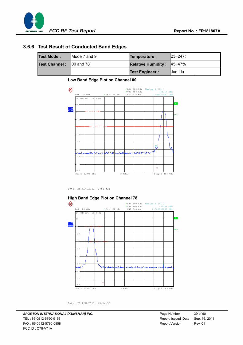
3.6.6 Test Result of Conducted Band Edges
Test Mode : Mode 7 and 9 Temperature : 23~24℃
Test Channel : 00 and 78 Relative Humidity : 45~47%
Test Engineer : Jun Liu
Low Band Edge Plot on Channel 00
High Band Edge Plot on Channel 78
A
Offset 14.8 dB
LVL
Ref 20 dBm Att 20 dB*
3 MHz/Start 2.375 GHz Stop 2.405 GHz
RBW 300 kHz
SWT 2.5 ms
*
VBW 300 kHz*
1 PKMAXH
-80
-70
-60
-50
-40
-30
-20
-10
0
10
20
1
Marker 1 [T1 ]
-46.17 dBm
2.399660000 GHz
D1 0.43 dBm
D2 -19.57 dBm
F1
Date: 29.AUG.2011 23:47:21
A
Offset 14.8 dB
LVL
Ref 20 dBm Att 20 dB*
3 MHz/Start 2.475 GHz Stop 2.505 GHz
RBW 300 kHz
SWT 2.5 ms
*
VBW 300 kHz*
1 PKMAXH
-80
-70
-60
-50
-40
-30
-20
-10
0
10
20
1
Marker 1 [T1 ]
-51.86 dBm
2.502000000 GHz
D1 -0.37 dBm
D2 -20.37 dBm
F1
Date: 29.AUG.2011 23:54:55

SPORTON INTERNATIONAL (KUNSHAN) INC. Page Number : 40 of 60
TEL : 86-0512-5790-0158 Report Issued Date : Sep. 16, 2011
FAX : 86-0512-5790-0958 Report Version : Rev. 01
FCC ID : Q78-V71A
FCC RF Test Report Report No. : FR181807A
3.7 Spurious Emission Measurement
3.7.1 Limit of Spurious Emission Measurement
All harmonics/spurious must be at least 20 dB down from the highest emission level within the
authorized band.
3.7.2 Measuring Instruments
See list of measuring instruments of this test report.
3.7.3 Test Procedure
1. The transmitter output was connected to the spectrum analyzer via a low lose cable.
2. Set RBW = 100 kHz, Video bandwidth (VBW) ≥ RBW, scan up through 10th harmonic. All
harmonics / spurs must be at least 20 dB down from the highest emission level within the
authorized band as measured with a 100 kHz RBW.
3.7.4 Test Setup

SPORTON INTERNATIONAL (KUNSHAN) INC. Page Number : 41 of 60
TEL : 86-0512-5790-0158 Report Issued Date : Sep. 16, 2011
FAX : 86-0512-5790-0958 Report Version : Rev. 01
FCC ID : Q78-V71A
FCC RF Test Report Report No. : FR181807A
3.7.5 Test Result
Test Mode : Mode 7 Temperature : 23~24℃
Test Channel : 00 Relative Humidity : 45~47%
Test Engineer : Jun Liu
Conducted Spurious Emission Plot between 30MHz ~ 3 GHz
Conducted Spurious Emission Plot between 3 GHz ~ 25 GHz
A
Offset 14.8 dB
LVL
Ref 20 dBm Att 20 dB*
297 MHz/Start 30 MHz Stop 3 GHz
*
*
RBW 100 kHz
VBW 300 kHz
SWT 300 ms
1 PKVIEW
-80
-70
-60
-50
-40
-30
-20
-10
0
10
20
1
Marker 1 [T1 ]
-47.55 dBm
2.566380000 GHz
D1 -20.9 dBm
Date: 29.AUG.2011 23:48:33
Ref 20 dBm Att 20 dB*
*
Offset 14.8 dB
A
LVL
RBW 100 kHz
VBW 300 kHz
SWT 2.2 s
*
Start 3 GHz Stop 25 GHz2.2 GHz/
1 PKVIEW
-80
-70
-60
-50
-40
-30
-20
-10
0
10
20
1
Marker 1 [T1 ]
-38.37 dBm
21.700000000 GHz
D1 -20.9 dBm
Date: 29.AUG.2011 23:48:55

SPORTON INTERNATIONAL (KUNSHAN) INC. Page Number : 42 of 60
TEL : 86-0512-5790-0158 Report Issued Date : Sep. 16, 2011
FAX : 86-0512-5790-0958 Report Version : Rev. 01
FCC ID : Q78-V71A
FCC RF Test Report Report No. : FR181807A
Test Mode : Mode 8 Temperature : 23~24℃
Test Channel : 39 Relative Humidity : 45~47%
Test Engineer : Jun Liu
Conducted Spurious Emission Plot between 30MHz ~ 3 GHz
Conducted Spurious Emission Plot between 3 GHz ~ 25 GHz
A
Offset 14.8 dB
LVL
Ref 20 dBm Att 20 dB*
297 MHz/Start 30 MHz Stop 3 GHz
*
*
RBW 100 kHz
VBW 300 kHz
SWT 300 ms
1 PKVIEW
-80
-70
-60
-50
-40
-30
-20
-10
0
10
20
1
Marker 1 [T1 ]
-47.09 dBm
2.798040000 GHz
D1 -21.31 dBm
Date: 29.AUG.2011 23:52:23
Ref 20 dBm Att 20 dB*
*
Offset 14.8 dB
A
LVL
RBW 100 kHz
VBW 300 kHz
SWT 2.2 s
*
Start 3 GHz Stop 25 GHz2.2 GHz/
1 PKVIEW
-80
-70
-60
-50
-40
-30
-20
-10
0
10
20
1
Marker 1 [T1 ]
-38.85 dBm
19.984000000 GHz
D1 -21.31 dBm
Date: 29.AUG.2011 23:52:45

SPORTON INTERNATIONAL (KUNSHAN) INC. Page Number : 43 of 60
TEL : 86-0512-5790-0158 Report Issued Date : Sep. 16, 2011
FAX : 86-0512-5790-0958 Report Version : Rev. 01
FCC ID : Q78-V71A
FCC RF Test Report Report No. : FR181807A
Test Mode : Mode 9 Temperature : 23~24℃
Test Channel : 78 Relative Humidity : 45~47%
Test Engineer : Jun Liu
Conducted Spurious Emission Plot between 30MHz ~ 3 GHz
Conducted Spurious Emission Plot between 3 GHz ~ 25 GHz
A
Offset 14.8 dB
LVL
Ref 20 dBm Att 20 dB*
297 MHz/Start 30 MHz Stop 3 GHz
*
*
RBW 100 kHz
VBW 300 kHz
SWT 300 ms
1 PKVIEW
-80
-70
-60
-50
-40
-30
-20
-10
0
10
20
1
Marker 1 [T1 ]
-47.82 dBm
2.970300000 GHz
D1 -22.26 dBm
Date: 29.AUG.2011 23:55:53
Ref 20 dBm Att 20 dB*
*
Offset 14.8 dB
A
LVL
RBW 100 kHz
VBW 300 kHz
SWT 2.2 s
*
Start 3 GHz Stop 25 GHz2.2 GHz/
1 PKVIEW
-80
-70
-60
-50
-40
-30
-20
-10
0
10
20
1
Marker 1 [T1 ]
-38.86 dBm
22.008000000 GHz
D1 -22.26 dBm
Date: 29.AUG.2011 23:56:15

SPORTON INTERNATIONAL (KUNSHAN) INC. Page Number : 44 of 60
TEL : 86-0512-5790-0158 Report Issued Date : Sep. 16, 2011
FAX : 86-0512-5790-0958 Report Version : Rev. 01
FCC ID : Q78-V71A
FCC RF Test Report Report No. : FR181807A
3.8 AC Conducted Emission Measurement
3.8.1 Limit of AC Conducted Emission
For equipment that is designed to be connected to the public utility (AC) power line, the radio
frequency voltage that is conducted back onto the AC power line on any frequency or frequencies
within the band 150 kHz to 30 MHz shall not exceed the limits in the following table.
Frequency of emission (MHz) Conducted limit (dBuV)
Quasi-peak Average
0.15-0.5 66 to 56* 56 to 46*
0.5-5 56 46
5-30 60 50
*Decreases with the logarithm of the frequency.
3.8.2 Measuring Instruments
See list of measuring instruments of this test report.
3.8.3 Test Procedures
1. Please follow the guidelines in ANSI C63.4-2003.
2. The EUT was placed 0.4 meter from the conducting wall of the shielding room was kept at least
80 centimeters from any other grounded conducting surface.
3. Connect EUT to the power mains through a line impedance stabilization network (LISN).
4. All the support units are connecting to the other LISN.
5. The LISN provides 50 ohm coupling impedance for the measuring instrument.
6. The FCC states that a 50 ohm, 50 microhenry LISN should be used.
7. Both sides of AC line were checked for maximum conducted interference.
8. The frequency range from 150 kHz to 30 MHz was searched.
9. Set the test-receiver system to Peak Detect Function and specified bandwidth with Maximum
Hold Mode.

SPORTON INTERNATIONAL (KUNSHAN) INC. Page Number : 45 of 60
TEL : 86-0512-5790-0158 Report Issued Date : Sep. 16, 2011
FAX : 86-0512-5790-0958 Report Version : Rev. 01
FCC ID : Q78-V71A
FCC RF Test Report Report No. : FR181807A
3.8.4 Test Setup

SPORTON INTERNATIONAL (KUNSHAN) INC. Page Number : 46 of 60
TEL : 86-0512-5790-0158 Report Issued Date : Sep. 16, 2011
FAX : 86-0512-5790-0958 Report Version : Rev. 01
FCC ID : Q78-V71A
FCC RF Test Report Report No. : FR181807A
3.8.5 Test Result of AC Conducted Emission
Test Mode : Mode 1 Temperature : 21~22℃
Test Engineer : Infi Li Relative Humidity : 42~43%
Test Voltage : 120Vac / 60Hz Phase : Line
Function Type : GSM 850 Idle + Bluetooth Link + WLAN Link + Adapter + Camera + GPS Rx
Remark : All emissions not reported here are more than 10 dB below the prescribed limit.

SPORTON INTERNATIONAL (KUNSHAN) INC. Page Number : 47 of 60
TEL : 86-0512-5790-0158 Report Issued Date : Sep. 16, 2011
FAX : 86-0512-5790-0958 Report Version : Rev. 01
FCC ID : Q78-V71A
FCC RF Test Report Report No. : FR181807A
Test Mode : Mode 1 Temperature : 21~22℃
Test Engineer : Infi Li Relative Humidity : 42~43%
Test Voltage : 120Vac / 60Hz Phase : Neutral
Function Type : GSM 850 Idle + Bluetooth Link + WLAN Link + Adapter + Camera + GPS Rx
Remark : All emissions not reported here are more than 10 dB below the prescribed limit.

SPORTON INTERNATIONAL (KUNSHAN) INC. Page Number : 48 of 60
TEL : 86-0512-5790-0158 Report Issued Date : Sep. 16, 2011
FAX : 86-0512-5790-0958 Report Version : Rev. 01
FCC ID : Q78-V71A
FCC RF Test Report Report No. : FR181807A
3.9 Radiated Emission Measurement
3.9.1 Limit of Radiated Emission
In any 100 kHz bandwidth outside the intentional radiator frequency band, all harmonics/spurious
must be at least 20 dB below the highest emission level within the authorized band. In addition,
radiated emissions which fall in the restricted bands must also comply with the FCC section 15.209
limits as below.
Frequency
(MHz)
Field Strength
(microvolts/meter)
Measurement Distance
(meters)
0.009 – 0.490 2400/F(kHz) 300
0.490 – 1.705 24000/F(kHz) 30
1.705 – 30.0 30 30
30 – 88 100 3
88 – 216 150 3
216 - 960 200 3
Above 960 500 3
3.9.2 Measuring Instruments
See list of measuring instruments of this test report.
3.9.3 Test Procedures
1. The testing follows the guidelines in FCC Public Notice DA 00-705 Measurement Guidelines.
2. Use the following spectrum analyzer settings:
(1) Span = wide enough to fully capture the emission being measured; RBW = 1 MHz for f 1
GHz, 100 kHz for f < 1 GHz; VBW RBW; Sweep = auto; Detector function = peak; Trace =
max hold.
(2) Above 18 GHz shall be extrapolated to the specified distance using an extrapolation factor
of 20 dB/decade from 3m to 1m.
Distance extrapolation factor = 20 log (specific distance [3m] / test distance [1m]) (dB)
3. Follow the guidelines in ANSI C63.4-2003 with respect to maximizing the emission by rotating
the EUT, measuring the emission for three EUT orthogonal planes, and adjusting the
measurement antenna height and polarization. A pre-amp and a high pass filter are used for
this test in order to get the good signal level.
4. Measured average value for the peak value is greater than 54 dBuv/m

SPORTON INTERNATIONAL (KUNSHAN) INC. Page Number : 49 of 60
TEL : 86-0512-5790-0158 Report Issued Date : Sep. 16, 2011
FAX : 86-0512-5790-0958 Report Version : Rev. 01
FCC ID : Q78-V71A
FCC RF Test Report Report No. : FR181807A
3.9.4 Test Setup
For radiated emissions below 30MHz
For radiated emissions from 30MHz to 1GHz

SPORTON INTERNATIONAL (KUNSHAN) INC. Page Number : 50 of 60
TEL : 86-0512-5790-0158 Report Issued Date : Sep. 16, 2011
FAX : 86-0512-5790-0958 Report Version : Rev. 01
FCC ID : Q78-V71A
FCC RF Test Report Report No. : FR181807A
For radiated emissions above 1GHz
3.9.5 Test Results of Radiated Emissions (9 kHz ~ 30 MHz)
Test Engineer : Chenmy Cheng Temperature : 23~24°C
Relative Humidity : 41~42%
Frequency Level Over Limit Limit Line Remark
(MHz) (dBuV) (dB) (dBuV)
- - - - See Note
Note:
The amplitude of spurious emissions that are attenuated by more than 20dB below the permissible
value has no need to be reported.
Distance extrapolation factor = 40 log (specific distance / test distance) (dB);
Limit line = specific limits (dBuV) + distance extrapolation factor.

SPORTON INTERNATIONAL (KUNSHAN) INC. Page Number : 51 of 60
TEL : 86-0512-5790-0158 Report Issued Date : Sep. 16, 2011
FAX : 86-0512-5790-0958 Report Version : Rev. 01
FCC ID : Q78-V71A
FCC RF Test Report Report No. : FR181807A
3.9.6 Test Result of Radiated Emission (30 MHz ~ 10th Harmonic)
Test Mode : Mode 1 Temperature : 23~24°C
Test Channel : 00 Relative Humidity : 41~42%
Test Engineer : Chenmy Cheng Polarization : Horizontal
Remark : 2402 MHz is Fundamental Signals which can be ignored.
Frequency Level Over Limit Read Antenna Cable Preamp Ant Table Remark
Limit Line Level Factor Loss Factor Pos Pos
( MHz ) ( dBuV/m ) ( dB ) ( dBuV/m ) (dBuV) ( dB ) ( dB ) ( dB ) ( cm ) ( deg )
37.83 24.68 -15.32 40 40.8 13.7 0.24 30.06 100 263 Peak
122.34 25.05 -18.45 43.5 42.79 11.78 0.45 29.97 - - Peak
254.64 27.14 -18.86 46 44.25 12.07 0.67 29.85 - - Peak
381.2 22.03 -23.97 46 35.58 15.49 0.83 29.87 - - Peak
871.2 23.02 -22.98 46 30.83 20.49 1.29 29.59 - - Peak
946.1 31.73 -22.27 54 39.23 20.71 1.33 29.54 - - Peak
2362.63 50.78 -23.22 74 48.57 32.81 3.38 33.98 100 236 Peak
2362.63 37.04 -16.96 54 34.83 32.81 3.38 33.98 100 236 Average
2402 101.73 - - 99.45 32.86 3.47 34.05 167 0 Peak
2402 86.91 - - 84.63 32.86 3.47 34.05 167 0 Average
2490.88 50.13 -23.87 74 47.59 33.05 3.72 34.23 100 116 Peak
2490.88 36.8 -17.2 54 34.26 33.05 3.72 34.23 100 116 Average

SPORTON INTERNATIONAL (KUNSHAN) INC. Page Number : 52 of 60
TEL : 86-0512-5790-0158 Report Issued Date : Sep. 16, 2011
FAX : 86-0512-5790-0958 Report Version : Rev. 01
FCC ID : Q78-V71A
FCC RF Test Report Report No. : FR181807A
Test Mode : Mode 1 Temperature : 23~24°C
Test Channel : 00 Relative Humidity : 41~42%
Test Engineer : Chenmy Cheng Polarization : Vertical
Remark : 2402 MHz is Fundamental Signals which can be ignored.
Frequency Level Over Limit Read Antenna Cable Preamp Ant Table Remark
Limit Line Level Factor Loss Factor Pos Pos
( MHz ) ( dBuV/m ) ( dB ) ( dBuV/m ) (dBuV) ( dB ) ( dB ) ( dB ) ( cm ) ( deg )
40.8 30.57 -9.43 40 48.73 11.64 0.25 30.05 100 266 Peak
57.54 27.74 -12.26 40 51.83 5.75 0.3 30.14 - - Peak
134.49 27.07 -16.43 43.5 45.28 11.3 0.48 29.99 - - Peak
477.1 24.27 -21.73 46 36.3 16.8 0.93 29.76 - - Peak
508.6 24.76 -21.24 46 36.16 17.36 0.96 29.72 - - Peak
949.6 31.09 -22.91 54 38.57 20.73 1.33 29.54 - - Peak
2350.66 50.32 -23.68 74 48.15 32.78 3.33 33.94 200 125 Peak
2350.66 37.12 -16.88 54 34.95 32.78 3.33 33.94 200 125 Average
2402 95.88 - - 93.6 32.86 3.47 34.05 200 145 Peak
2402 82.56 - - 80.28 32.86 3.47 34.05 200 145 Average
2484.23 49.08 -24.92 74 46.59 33.01 3.68 34.2 200 226 Peak
2484.23 37.25 -16.75 54 34.76 33.01 3.68 34.2 200 226 Average

SPORTON INTERNATIONAL (KUNSHAN) INC. Page Number : 53 of 60
TEL : 86-0512-5790-0158 Report Issued Date : Sep. 16, 2011
FAX : 86-0512-5790-0958 Report Version : Rev. 01
FCC ID : Q78-V71A
FCC RF Test Report Report No. : FR181807A
Test Mode : Mode 2 Temperature : 23~24°C
Test Channel : 39 Relative Humidity : 41~42%
Test Engineer : Chenmy Cheng Polarization : Horizontal
Remark : 2441 MHz is Fundamental Signals which can be ignored.
Frequency Level Over Limit Read Antenna Cable Preamp Ant Table Remark
Limit Line Level Factor Loss Factor Pos Pos
( MHz ) ( dBuV/m ) ( dB ) ( dBuV/m ) (dBuV) ( dB ) ( dB ) ( dB ) ( cm ) ( deg )
37.02 23.66 -16.34 40 39.3 14.19 0.24 30.07 100 26 Peak
40.8 31.18 -8.82 40 49.34 11.64 0.25 30.05 100 116 Peak
54.03 20.49 -19.51 40 43.84 6.49 0.29 30.13 - - Peak
135.57 28 -15.5 43.5 46.3 11.21 0.48 29.99 - - Peak
254.37 27.21 -18.79 46 44.33 12.06 0.67 29.85 - - Peak
254.64 26.75 -19.25 46 43.86 12.07 0.67 29.85 - - Peak
381.2 20.88 -25.12 46 34.43 15.49 0.83 29.87 - - Peak
773.2 21.87 -24.13 46 30.34 19.88 1.21 29.56 - - Peak
946.1 29.71 -24.29 54 37.21 20.71 1.33 29.54 - - Peak
2347.24 37.15 -16.85 54 34.98 32.78 3.33 33.94 100 126 Average
2347.24 49.13 -24.87 74 46.96 32.78 3.33 33.94 100 126 Peak
2441 101.19 - - 98.79 32.95 3.6 34.15 160 0 Peak
2441 85.13 - - 82.73 32.95 3.6 34.15 160 0 Average
2497.15 48.74 -25.26 74 46.2 33.05 3.72 34.23 100 118 Peak
2497.15 37.13 -16.87 54 34.59 33.05 3.72 34.23 100 118 Average

SPORTON INTERNATIONAL (KUNSHAN) INC. Page Number : 54 of 60
TEL : 86-0512-5790-0158 Report Issued Date : Sep. 16, 2011
FAX : 86-0512-5790-0958 Report Version : Rev. 01
FCC ID : Q78-V71A
FCC RF Test Report Report No. : FR181807A
Test Mode : Mode 2 Temperature : 23~24°C
Test Channel : 39 Relative Humidity : 41~42%
Test Engineer : Chenmy Cheng Polarization : Vertical
Remark : 2441 MHz is Fundamental Signals which can be ignored.
Frequency Level Over Limit Read Antenna Cable Preamp Ant Table Remark
Limit Line Level Factor Loss Factor Pos Pos
( MHz ) ( dBuV/m ) ( dB ) ( dBuV/m ) (dBuV) ( dB ) ( dB ) ( dB ) ( cm ) ( deg )
40.8 31.18 -8.82 40 49.34 11.64 0.25 30.05 100 116 Peak
135.57 28 -15.5 43.5 46.3 11.21 0.48 29.99 - - Peak
254.64 26.75 -19.25 46 43.86 12.07 0.67 29.85 - - Peak
477.1 24.79 -21.21 46 36.82 16.8 0.93 29.76 - - Peak
872.6 23.66 -22.34 46 31.47 20.48 1.29 29.58 - - Peak
946.1 30.63 -23.37 54 38.13 20.71 1.33 29.54 - - Peak
2355.03 49.68 -24.32 74 47.47 32.81 3.38 33.98 100 119 Peak
2355.03 37.1 -16.9 54 34.89 32.81 3.38 33.98 100 119 Average
2441 95.64 - - 93.24 32.95 3.6 34.15 200 127 Peak
2441 81.68 - - 79.28 32.95 3.6 34.15 200 127 Average
2485.18 48.86 -25.14 74 46.37 33.01 3.68 34.2 200 112 Peak
2485.18 37.11 -16.89 54 34.62 33.01 3.68 34.2 200 112 Average

SPORTON INTERNATIONAL (KUNSHAN) INC. Page Number : 55 of 60
TEL : 86-0512-5790-0158 Report Issued Date : Sep. 16, 2011
FAX : 86-0512-5790-0958 Report Version : Rev. 01
FCC ID : Q78-V71A
FCC RF Test Report Report No. : FR181807A
Test Mode : Mode 3 Temperature : 23~24°C
Test Channel : 78 Relative Humidity : 41~42%
Test Engineer : Chenmy Cheng Polarization : Horizontal
Remark : 2480 MHz is Fundamental Signals which can be ignored.
Frequency Level Over Limit Read Antenna Cable Preamp Ant Table Remark
Limit Line Level Factor Loss Factor Pos Pos
( MHz ) ( dBuV/m ) ( dB ) ( dBuV/m ) (dBuV) ( dB ) ( dB ) ( dB ) ( cm ) ( deg )
37.83 24.29 -15.71 40 40.41 13.7 0.24 30.06 100 228 Peak
54.03 21.46 -18.54 40 44.81 6.49 0.29 30.13 - - Peak
254.37 27.61 -18.39 46 44.73 12.06 0.67 29.85 - - Peak
381.2 20.58 -25.42 46 34.13 15.49 0.83 29.87 - - Peak
778.8 21.94 -24.06 46 30.42 19.87 1.22 29.57 - - Peak
946.1 30.8 -23.2 54 38.3 20.71 1.33 29.54 - - Peak
2382 49.35 -24.65 74 47.11 32.83 3.42 34.01 100 26 Peak
2382 36.8 -17.2 54 34.56 32.83 3.42 34.01 100 26 Average
2480 99.85 - - 97.36 33.01 3.68 34.2 100 0 Peak
2480 85.15 - - 82.66 33.01 3.68 34.2 100 0 Average
2484.71 44.63 -29.37 74 42.14 33.01 3.68 34.2 200 166 Peak
2484.71 33.23 -20.77 54 30.74 33.01 3.68 34.2 200 166 Average

SPORTON INTERNATIONAL (KUNSHAN) INC. Page Number : 56 of 60
TEL : 86-0512-5790-0158 Report Issued Date : Sep. 16, 2011
FAX : 86-0512-5790-0958 Report Version : Rev. 01
FCC ID : Q78-V71A
FCC RF Test Report Report No. : FR181807A
Test Mode : Mode 3 Temperature : 23~24°C
Test Channel : 78 Relative Humidity : 41~42%
Test Engineer : Chenmy Cheng Polarization : Vertical
Remark : 2480 MHz is Fundamental Signals which can be ignored.
Frequency Level Over Limit Read Antenna Cable Preamp Ant Table Remark
Limit Line Level Factor Loss Factor Pos Pos
( MHz ) ( dBuV/m ) ( dB ) ( dBuV/m ) (dBuV) ( dB ) ( dB ) ( dB ) ( cm ) ( deg )
40.8 31.32 -8.68 40 49.48 11.64 0.25 30.05 100 287 Peak
67.53 27.23 -12.77 40 51.72 5.27 0.33 30.09 - - Peak
135.84 28.44 -15.06 43.5 46.74 11.21 0.48 29.99 - - Peak
508.6 23.51 -22.49 46 34.91 17.36 0.96 29.72 - - Peak
871.2 23.58 -22.42 46 31.39 20.49 1.29 29.59 - - Peak
946.1 30.39 -23.61 54 37.89 20.71 1.33 29.54 - - Peak
2344 49.25 -24.75 74 47.08 32.78 3.33 33.94 100 229 Peak
2344 36.73 -17.27 54 34.56 32.78 3.33 33.94 100 229 Average
2480 95.56 - - 93.07 33.01 3.68 34.2 200 268 Peak
2480 81.43 - - 78.94 33.01 3.68 34.2 200 268 Average
2485.07 44.12 -29.88 74 41.63 33.01 3.68 34.2 200 226 Peak
2485.07 33.56 -20.44 54 31.07 33.01 3.68 34.2 200 226 Average

SPORTON INTERNATIONAL (KUNSHAN) INC. Page Number : 57 of 60
TEL : 86-0512-5790-0158 Report Issued Date : Sep. 16, 2011
FAX : 86-0512-5790-0958 Report Version : Rev. 01
FCC ID : Q78-V71A
FCC RF Test Report Report No. : FR181807A
3.10 Antenna Requirements
3.10.1 Standard Applicable
If directional gain of transmitting antennas is greater than 6dBi, the power shall be reduced by the
same level in dB comparing to gain minus 6dBi. The use of a permanently attached antenna or of an
antenna that uses a unique coupling to the intentional radiator shall be considered sufficient to
comply with the FCC rule.
3.10.2 Antenna Connected Construction
The antennas type used in this product is Fixed Internal Antenna without connector and it is
considered to meet antenna requirement.
3.10.3 Antenna Gain
The antenna peak gain of EUT is less than 6 dBi. Therefore, it is not necessary to reduce maximum
peak output power limit.

SPORTON INTERNATIONAL (KUNSHAN) INC. Page Number : 58 of 60
TEL : 86-0512-5790-0158 Report Issued Date : Sep. 16, 2011
FAX : 86-0512-5790-0958 Report Version : Rev. 01
FCC ID : Q78-V71A
FCC RF Test Report Report No. : FR181807A
4 List of Measuring Equipment
Instrument Manufacturer Model No. Serial No. CharacteristicsCalibration
Date Due Date Remark
Spectrum
Analyzer R&S FSP40 100319 9kHz~40GHz Jan. 07, 2011 Jan. 06, 2012
Conducted
(TH01-KS)
EMI Receiver R&S ESCI7 100768 9kHz~7GHz Jun. 02, 2011 Jun. 01, 2012 Conduction
(CO01-KS)
LISN MessTec AN3016 60103 9kHz~30MHz Jan. 07, 2011 Jan. 06, 2012 Conduction
(CO01-KS)
LISN MessTec AN3016 60105 9kHz~30MHz Jan. 07, 2011 Jan. 06, 2012 Conduction
(CO01-KS)
AC Power Source Chroma 61602 ABP00000
0811 N/A Nov. 10, 2010 Nov. 09, 2011
Conduction
(CO01-KS)
System Simulator R&S CMU200 837587/06
6 Full-Band Jan. 07, 2011 Jan. 06, 2012 Conduction
(CO01-KS)
EMI Test Receiver R&S ESCI 100534 9kHz~3GHz Nov. 16, 2010 Nov. 15, 2011 Radiation
(03CH01-KS)
Spectrum
Analyzer R&S FSP40 100319 9kHz~40GHz Jan. 07, 2011 Jan. 06, 2012
Radiation
(03CH01-KS)
Bilog Antenna SCHAFFNER CBL6112D 23182 25MHz~2GHz Dec. 07, 2010 Dec. 06, 2011 Radiation
(03CH01-KS)
Double Ridge
Horn Antenna EMCO 3117 00075959 1GHz~18GHz Jan. 07, 2011 Jan. 06, 2012
Radiation
(03CH01-KS)
Amplifier Wireless FPA-6592G 060004 30MHz~2GHz Dec. 09, 2010 Dec. 08, 2011 Radiation
(03CH01-KS)
Amplifier Agilent 8449B 3008A023
70 1GHz~26.5GHz Jan. 07, 2011 Jan. 06, 2012
Radiation
(03CH01-KS)
Active Horn
Antenna com-power AHA-118 701023 1G-18GHz Nov. 09, 2010 Nov. 08, 2011
Radiation
(03CH01-KS)
SHF-EHF Horn Schwarzbeck BBHA 9170BBHA1702
49 15GHz -40GHz Oct. 15, 2010 Oct.14, 2011
Radiation
(03CH01-KS)
Bluetooth
Base Station ANRITSU MT8852B
6K000049
35 BT EDR Sep. 17, 2010 Sep. 16, 2011 -

SPORTON INTERNATIONAL (KUNSHAN) INC. Page Number : 59 of 60
TEL : 86-0512-5790-0158 Report Issued Date : Sep. 16, 2011
FAX : 86-0512-5790-0958 Report Version : Rev. 01
FCC ID : Q78-V71A
FCC RF Test Report Report No. : FR181807A
5 Uncertainty of Evaluation
Uncertainty of Conducted Emission Measurement (150 kHz ~ 30 MHz)
Contribution Uncertainty of Xi
u(Xi) dB
Probability Distribution
Receiver Reading 0.10 Normal (k=2) 0.05
Cable Loss 0.10 Normal (k=2) 0.05
AMN Insertion Loss 2.50 Rectangular 0.63
Receiver Specification 1.50 Rectangular 0.43
Site Imperfection 1.39 Rectangular 0.80
Mismatch +0.34 / -0.35 U-Shape 0.24
Combined Standard Uncertainty Uc(y) 1.13
Measuring Uncertainty for a Level of Confidence of 95% (U = 2Uc(y))
2.26
Uncertainty of Radiated Emission Measurement (30 MHz ~ 1000 MHz)
Contribution Uncertainty of Xi
u(Xi) dB
Probability Distribution
Receiver Reading 0.41 Normal (k=2) 0.21
Antenna Factor Calibration 0.83 Normal (k=2) 0.42
Cable Loss Calibration 0.25 Normal (k=2) 0.13
Pre-Amplifier Gain Calibration 0.27 Normal (k=2) 0.14
RCV/SPA Specification 2.50 Rectangular 0.72
Antenna Factor Interpolation for Frequency 1.00 Rectangular 0.29
Site Imperfection 1.43 Rectangular 0.83
Mismatch +0.39 / -0.41 U-Shape 0.28
Combined Standard Uncertainty Uc(y) 1.27
Measuring Uncertainty for a Level of Confidence of 95% (U = 2Uc(y))
2.54

SPORTON INTERNATIONAL (KUNSHAN) INC. Page Number : 60 of 60
TEL : 86-0512-5790-0158 Report Issued Date : Sep. 16, 2011
FAX : 86-0512-5790-0958 Report Version : Rev. 01
FCC ID : Q78-V71A
FCC RF Test Report Report No. : FR181807A
Uncertainty of Radiated Emission Measurement (1 GHz ~ 40 GHz)
Contribution Uncertainty of Xi
u(Xi) Ci Ci * u(Xi)dB
Probability Distribution
Receiver Reading ±0.10 Normal (k=2) 0.10 1 0.10
Antenna Factor Calibration ±1.70 Normal (k=2) 0.85 1 0.85
Cable Loss Calibration ±0.50 Normal (k=2) 0.25 1 0.25
Receiver Correction ±2.00 Rectangular 1.15 1 1.15
Antenna Factor Directional ±1.50 Rectangular 0.87 1 0.87
Site Imperfection ±2.80 Triangular 1.14 1 1.14
Mismatch Receiver VSWR 1 = 0.197 Antenna VSWR 2 = 0.194
Uncertainty = 20Log(1-1*2)
+0.34 / -0.35 U-Shape 0.244 1 0.244
Combined Standard Uncertainty Uc(y)
2.36
Measuring Uncertainty for a Level of Confidence of 95%
(U = 2Uc(y)) 4.72

SPORTON INTERNATIONAL (KUNSHAN) INC. Page Number : A1 of A1
TEL : 86-0512-5790-0158 Report Issued Date : Sep. 16, 2011
FAX : 86-0512-5790-0958 Report Version : Rev. 01
FCC ID : Q78-V71A
FCC RF Test Report Report No. : FR181807A
Appendix A. Photographs of EUT
Please refer to Sporton report number EP181807 as below.