Embed Size (px)
Citation preview

FCC Radio Test Report Report No. : FR740822-02
SPORTON INTERNATIONAL INC. Page No. : 2 of 39
TEL : 886-3-327-3456 Report Version : Rev. 04
FAX : 886-3-327-0973 Issued Date : Aug. 23, 2017
FCC ID: 2ALBB-A11
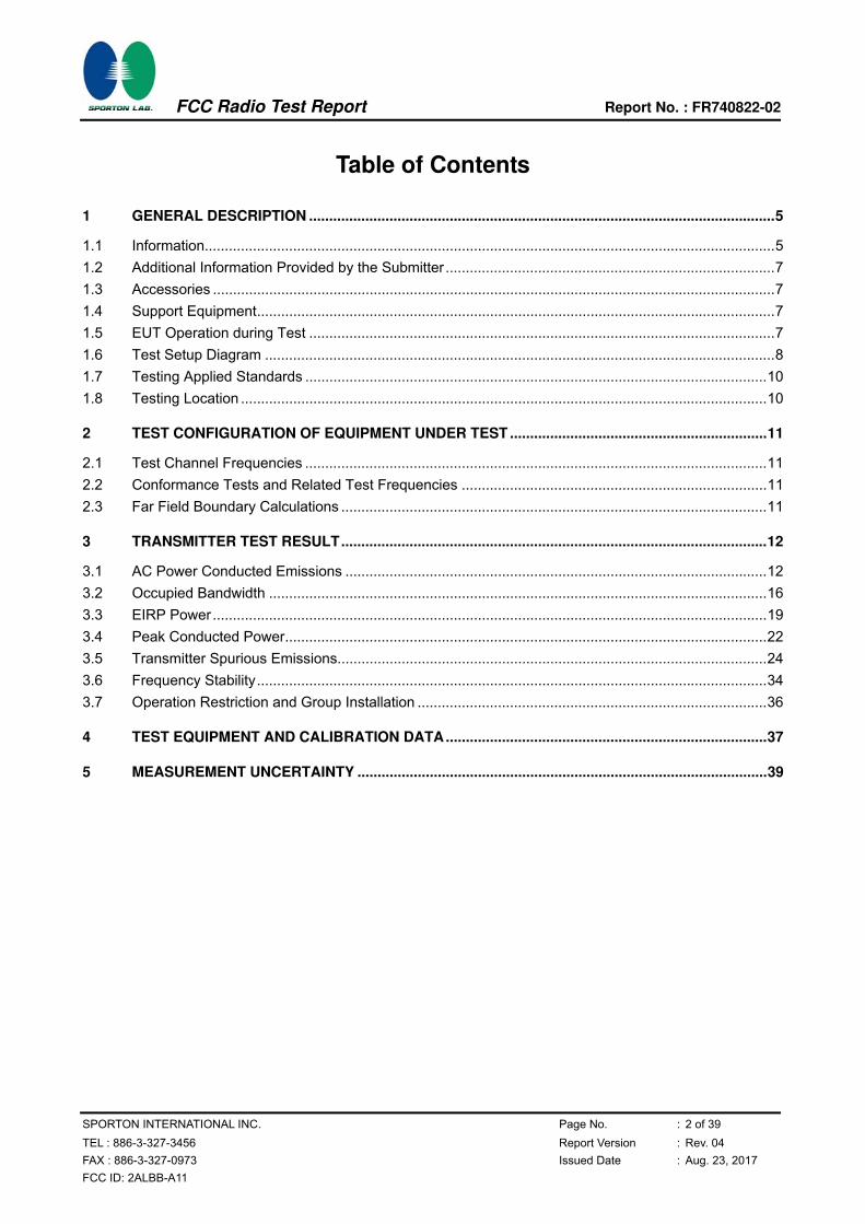
Table of Contents
1 GENERAL DESCRIPTION ....................................................................................................................5
1.1 Information..............................................................................................................................................5 1.2 Additional Information Provided by the Submitter ..................................................................................7 1.3 Accessories ............................................................................................................................................7 1.4 Support Equipment.................................................................................................................................7 1.5 EUT Operation during Test ....................................................................................................................7 1.6 Test Setup Diagram ...............................................................................................................................8 1.7 Testing Applied Standards ...................................................................................................................10 1.8 Testing Location ...................................................................................................................................10
2 TEST CONFIGURATION OF EQUIPMENT UNDER TEST ................................................................11
2.1 Test Channel Frequencies ...................................................................................................................11 2.2 Conformance Tests and Related Test Frequencies ............................................................................11 2.3 Far Field Boundary Calculations ..........................................................................................................11
3 TRANSMITTER TEST RESULT..........................................................................................................12
3.1 AC Power Conducted Emissions .........................................................................................................12 3.2 Occupied Bandwidth ............................................................................................................................16 3.3 EIRP Power..........................................................................................................................................19 3.4 Peak Conducted Power........................................................................................................................22 3.5 Transmitter Spurious Emissions...........................................................................................................24 3.6 Frequency Stability...............................................................................................................................34 3.7 Operation Restriction and Group Installation .......................................................................................36
4 TEST EQUIPMENT AND CALIBRATION DATA................................................................................37
5 MEASUREMENT UNCERTAINTY ......................................................................................................39

FCC Radio Test Report Report No. : FR740822-02
SPORTON INTERNATIONAL INC. Page No. : 3 of 39
TEL : 886-3-327-3456 Report Version : Rev. 04
FAX : 886-3-327-0973 Issued Date : Aug. 23, 2017
FCC ID: 2ALBB-A11
Summary of Test Result
Standard Requirements and Conformance Test Specifications
Report
Clause
Ref. Std.
Clause Description Result Remark
3.1 FCC 15.207 AC Power Conducted Emissions Complied -
3.2 FCC 15.255(d) Occupied Bandwidth Complied -
3.3 FCC 15.255(b)(1) EIRP Power Complied -
3.4 FCC 15.255(d) Peak Conducted Power Complied -
3.5 FCC 15.255(c) Transmitter Spurious Emissions Complied -
0 FCC 15.255(e) Frequency Stability Complied -
3.7 FCC 15.255(a),(g) Operation Restriction and Group Installation Complied -

FCC Radio Test Report Report No. : FR740822-02
SPORTON INTERNATIONAL INC. Page No. : 4 of 39
TEL : 886-3-327-3456 Report Version : Rev. 04
FAX : 886-3-327-0973 Issued Date : Aug. 23, 2017
FCC ID: 2ALBB-A11
Revision History
REPORT NO. VERSION DESCRIPTION ISSUED DATE
FR740822-02 Rev. 01 Initial issue of report Aug. 07, 2017
FR740822-02 Rev. 02
1. Updating the AC Power Conducted
Emission Test Data and Photo.
2. Adding the information of Test Result
of EIRP Power.
3. Revising 1GHz plots in Transmitter
Spurious Emissions.
4. Adding the information of Transmitter
Spurious Emissions.
5. Revising the information of User
Condition.
6. Revising the information of Equipment
Use Condition.
Aug. 18, 2017
FR740822-02 Rev. 03 Revising Test Setup Diagram
(AC Power Conducted Emissions) Aug. 21, 2017
FR740822-02 Rev. 04
1. Revising the information of Transmit
Operating Modes
2. Adding the low pass filter in the
equipment list.(section 4: Test
Equipment and Calibration Data)
Aug. 23, 2017

FCC Radio Test Report Report No. : FR740822-02
SPORTON INTERNATIONAL INC. Page No. : 5 of 39
TEL : 886-3-327-3456 Report Version : Rev. 04
FAX : 886-3-327-0973 Issued Date : Aug. 23, 2017
FCC ID: 2ALBB-A11
1 General Description
1.1 Information
1.1.1 The Channel Plan(s)
Frequency Range 60.48 GHz
1.1.2 Transmit Operating Modes
The Different Transmit Operating Modes
Operating mode 1: Smart Antenna Systems - with beam forming
Operating mode 2: Smart Antenna Systems - without beam forming
Operating mode 3: Single Antenna Equipment
1.1.3 Antenna Information
Antenna Information
Equipment placed on the market without antennas
Integral antenna
Integral antenna gain 0 dB
Temporary RF connector provided
No temporary RF connector provided
External antenna (dedicated antennas)
Single power level with corresponding antenna(s)
Multiple power settings and corresponding antenna(s)

FCC Radio Test Report Report No. : FR740822-02
SPORTON INTERNATIONAL INC. Page No. : 6 of 39
TEL : 886-3-327-3456 Report Version : Rev. 04
FAX : 886-3-327-0973 Issued Date : Aug. 23, 2017
FCC ID: 2ALBB-A11
1.1.4 Power Levels
Applicable power levels Conducted EIRP
Antenna gain 0 dBi
Highest setting (Phigh): (dBm) Frequency (GHz)
Modulation AV Power Peak Power
60.48 BPSK -4.08 4.81
1.1.5 Extreme Operating
The Extreme Operating Temperature Range that Apply to the Equipment
-20 °C to +50 °C
0 °C to +40 °C
Other: -10 °C to 55 °C
EUT Power Type From Power Adapter or Battery
Supply Voltage AC State AC voltage 120 V
Supply Voltage DC - Li-ion Polymer
Rechargeable Battery
State DC voltage 3.85 V
1.1.6 Equipment Use Condition
Equipment Use Condition
Fixed field disturbance sensors at 61-61.5GHz
Except fixed field disturbance sensors at 61-61.5GHz
Except fixed field disturbance sensors
1.1.7 User Condition
Intended Operation
Indoor
Outdoor
FCC Radio Test Report Report No. : FR740822-02
SPORTON INTERNATIONAL INC. Page No. : 7 of 39
TEL : 886-3-327-3456 Report Version : Rev. 04
FAX : 886-3-327-0973 Issued Date : Aug. 23, 2017
FCC ID: 2ALBB-A11
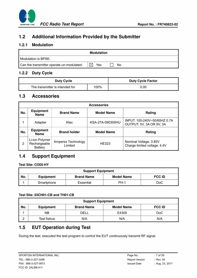
1.2 Additional Information Provided by the Submitter
1.2.1 Modulation
Modulation
Modulation is BPSK.
Can the transmitter operate un-modulated: Yes No
1.2.2 Duty Cycle
Duty Cycle Duty Cycle Factor
The transmitter is intended for 100% 0.00
1.3 Accessories
Accessories
No. Equipment
Name Brand Name Model Name Rating
1 Adapter Ktec KSA-27A-090300HU INPUT: 100-240V~50/60HZ 0.7A OUTPUT: 5V, 3A OR 9V, 3A
No. Equipment
Name Brand holder Model Name Rating
2 Li-ion Polymer Rechargeable
Battery
Amperex Technology Limited
HE323 Nominal Voltage: 3.85V Charge limited voltage: 4.4V
1.4 Support Equipment
Test Site: CO05-HY
Support Equipment
No. Equipment Brand Name Model Name FCC ID
1 Smartphone Essential PH-1 DoC
Test Site: 03CH01-CB and TH01-CB
Support Equipment
No. Equipment Brand Name Model Name FCC ID
1 NB DELL E4300 DoC
2 Test fixtrue N/A N/A N/A
1.5 EUT Operation during Test
During the test, executed the test program to control the EUT continuously transmit RF signal.

FCC Radio Test Report Report No. : FR740822-02
SPORTON INTERNATIONAL INC. Page No. : 8 of 39
TEL : 886-3-327-3456 Report Version : Rev. 04
FAX : 886-3-327-0973 Issued Date : Aug. 23, 2017
FCC ID: 2ALBB-A11
1.6 Test Setup Diagram
Test Setup Diagram - AC Power Conducted Emissions
Item Connection Shielded Length
1 Power cable No 1.8m
FCC Radio Test Report Report No. : FR740822-02
SPORTON INTERNATIONAL INC. Page No. : 9 of 39
TEL : 886-3-327-3456 Report Version : Rev. 04
FAX : 886-3-327-0973 Issued Date : Aug. 23, 2017
FCC ID: 2ALBB-A11
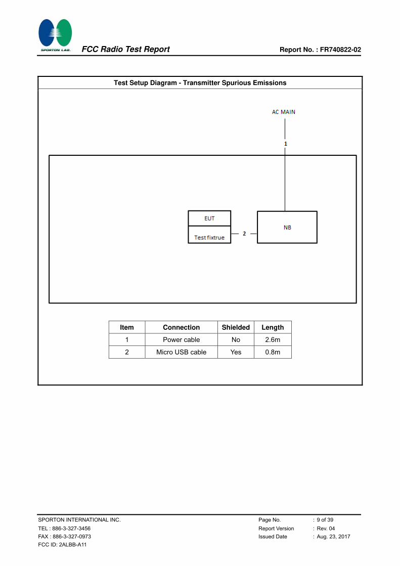
Test Setup Diagram - Transmitter Spurious Emissions
Item Connection Shielded Length
1 Power cable No 2.6m
2 Micro USB cable Yes 0.8m
FCC Radio Test Report Report No. : FR740822-02
SPORTON INTERNATIONAL INC. Page No. : 10 of 39
TEL : 886-3-327-3456 Report Version : Rev. 04
FAX : 886-3-327-0973 Issued Date : Aug. 23, 2017
FCC ID: 2ALBB-A11
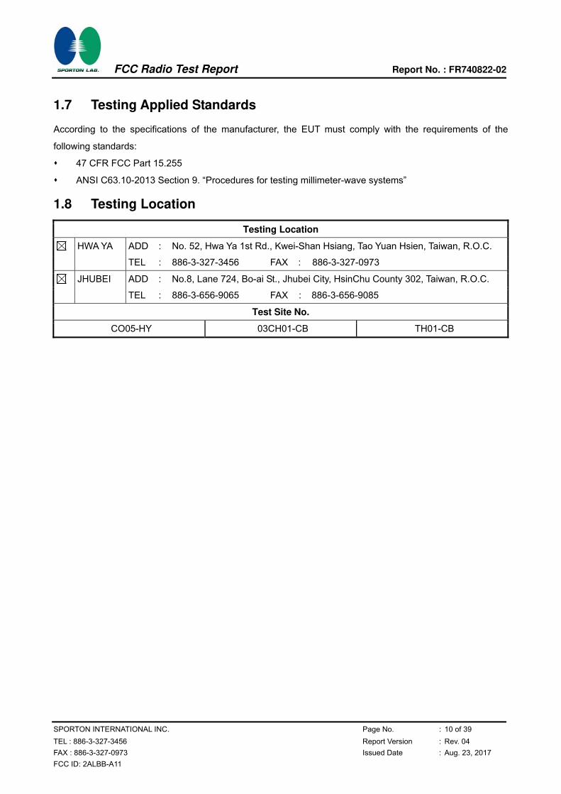
1.7 Testing Applied Standards
According to the specifications of the manufacturer, the EUT must comply with the requirements of the
following standards:
47 CFR FCC Part 15.255
ANSI C63.10-2013 Section 9. “Procedures for testing millimeter-wave systems”
1.8 Testing Location
Testing Location
HWA YA ADD : No. 52, Hwa Ya 1st Rd., Kwei-Shan Hsiang, Tao Yuan Hsien, Taiwan, R.O.C.
TEL : 886-3-327-3456 FAX : 886-3-327-0973
JHUBEI ADD : No.8, Lane 724, Bo-ai St., Jhubei City, HsinChu County 302, Taiwan, R.O.C.
TEL : 886-3-656-9065 FAX : 886-3-656-9085
Test Site No.
CO05-HY 03CH01-CB TH01-CB

FCC Radio Test Report Report No. : FR740822-02
SPORTON INTERNATIONAL INC. Page No. : 11 of 39
TEL : 886-3-327-3456 Report Version : Rev. 04
FAX : 886-3-327-0973 Issued Date : Aug. 23, 2017
FCC ID: 2ALBB-A11
2 Test Configuration of Equipment under Test
2.1 Test Channel Frequencies
Nominal Channel Bandwidth
60.48
2.2 Conformance Tests and Related Test Frequencies
Test Item Test Frequencies (GHz)
AC Power Conducted Emissions CTX
Occupied Bandwidth 60.48
EIRP Power 60.48
Peak Conducted Power 60.48
Transmitter Spurious Emissions (below 1 GHz) CTX
Transmitter Spurious Emissions (1 GHz-40 GHz) 60.48
Transmitter Spurious Emissions (above 40 GHz) 60.48
Frequency Stability Un-Modulation
Note: The EUT was performed in X axis, Y axis and Z axis position. The worst case was found in Y axis, so it
was selected to perform test and its test result was written in the report.
2.3 Far Field Boundary Calculations
The far-field boundary is given as:
far field = (2 * L^2) /λ
where:
L = Largest Antenna Dimension, including the reflector, in meters
λ= wavelength in meters
Far Field (m)
Frequency (GHz) L (m) Lambda (m) d(Far Field) (m) d(Far Field) (cm)
60.48 0.0022 0.0049603 0.0020 0.20
FCC Radio Test Report Report No. : FR740822-02
SPORTON INTERNATIONAL INC. Page No. : 12 of 39
TEL : 886-3-327-3456 Report Version : Rev. 04
FAX : 886-3-327-0973 Issued Date : Aug. 23, 2017
FCC ID: 2ALBB-A11
3 Transmitter Test Result
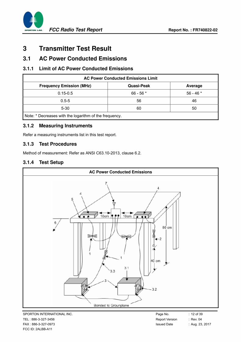
3.1 AC Power Conducted Emissions
3.1.1 Limit of AC Power Conducted Emissions
AC Power Conducted Emissions Limit
Frequency Emission (MHz) Quasi-Peak Average
0.15-0.5 66 - 56 * 56 - 46 *
0.5-5 56 46
5-30 60 50
Note: * Decreases with the logarithm of the frequency.
3.1.2 Measuring Instruments
Refer a measuring instruments list in this test report.
3.1.3 Test Procedures
Method of measurement: Refer as ANSI C63.10-2013, clause 6.2.
3.1.4 Test Setup
AC Power Conducted Emissions

FCC Radio Test Report Report No. : FR740822-02
SPORTON INTERNATIONAL INC. Page No. : 13 of 39
TEL : 886-3-327-3456 Report Version : Rev. 04
FAX : 886-3-327-0973 Issued Date : Aug. 23, 2017
FCC ID: 2ALBB-A11
AC Power Conducted Emissions
1. Interconnecting cables that hang closer than 40 cm to the ground plane shall be folded back and forth
in the center forming a bundle 30 cm to 40 cm long (see ANSI C63.10, clause 6.2.3.2).
2. I/O cables that are not connected to an accessory shall be bundled in the center. The end of the cable
may be terminated, if required, using the correct terminating impedance. The overall length shall not
exceed 1 m (see ANSI C63.10, clause 6.2.2).
3. EUT connected to one LISN. Unused LISN measuring port connectors shall be terminated in 50 ohm
loads. LISN can be placed on top of, or immediately beneath, reference ground plane (see ANSI
C63.10, clauses 6.2.2 and 6.2.3).
3.1. All other equipment powered from additional LISN(s).
3.2. A multiple-outlet strip can be used for multiple power cords of non-EUT equipment.
3.3. LISN at least 80 cm from nearest part of EUT chassis.
4. Non-EUT components of EUT system being tested.
5. Rear of EUT, including peripherals, shall all be aligned and flush with edge of tabletop (see ANSI
C63.10, clause 6.2.3.2).
6. Edge of tabletop shall be 40 cm removed from a vertical conducting plane that is bonded to the ground
plane (see ANSI C63.10, clause 6.2.2 for options).
7. Antenna may be integral or detachable. If detachable, the antenna shall be attached for this test.
3.1.5 Test Result of AC Power Conducted Emissions
Test Conditions see ANSI C63.10, clause 5.11
Test Setup see ANSI C63.10, clause 6.2.3
NOTE 1: If equipment having different channel plan and nominal channel bandwidth modes (see test report
clause 1.1.1), the measurements are uninfluenced by different channel plan and nominal channel
bandwidth modes, may not need to be repeated for all modes. If equipment having different
transmit operating modes (see test report clause 1.1.2), the measurements are uninfluenced by
different transmit operating modes, may not need to be repeated for all the operating modes.
Similar, if the equipment supports different modulations and/or data rates, the measurements
described in ANSI C63.10, clause 5.12 may not need to be repeated for all these modulations and
data rates. Simple comparison of engineering test across all operating modes, modulations and
data rates may need to be performed to define the worse case combination to be used for the
conformance testing.
NOTE 2: “>20dB” means the tables in this clause should only list values of spurious emissions that exceed
the level of 20 dB below the applicable limit, see ANSI C63.4, clause 10.1.8.1.

FCC Radio Test Report Report No. : FR740822-02
SPORTON INTERNATIONAL INC. Page No. : 14 of 39
TEL : 886-3-327-3456 Report Version : Rev. 04
FAX : 886-3-327-0973 Issued Date : Aug. 23, 2017
FCC ID: 2ALBB-A11
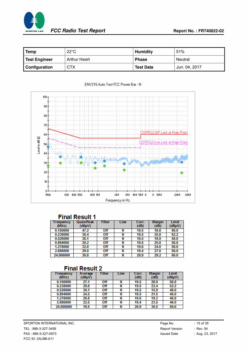
Temp 22°C Humidity 51%
Test Engineer Arthur Hsieh Phase Line
Configuration CTX Test Data Jun. 04, 2017
FCC Radio Test Report Report No. : FR740822-02
SPORTON INTERNATIONAL INC. Page No. : 15 of 39
TEL : 886-3-327-3456 Report Version : Rev. 04
FAX : 886-3-327-0973 Issued Date : Aug. 23, 2017
FCC ID: 2ALBB-A11
Temp 22°C Humidity 51%
Test Engineer Arthur Hsieh Phase Neutral
Configuration CTX Test Data Jun. 04, 2017
FCC Radio Test Report Report No. : FR740822-02
SPORTON INTERNATIONAL INC. Page No. : 16 of 39
TEL : 886-3-327-3456 Report Version : Rev. 04
FAX : 886-3-327-0973 Issued Date : Aug. 23, 2017
FCC ID: 2ALBB-A11
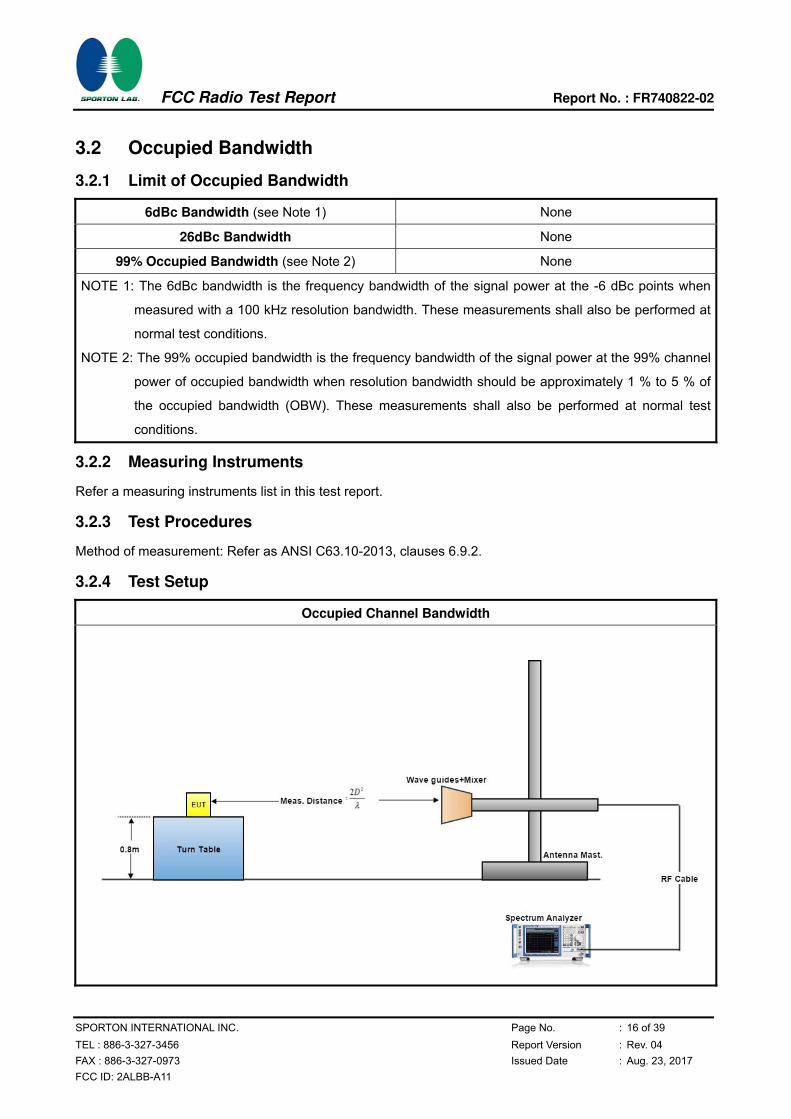
3.2 Occupied Bandwidth
3.2.1 Limit of Occupied Bandwidth
6dBc Bandwidth (see Note 1) None
26dBc Bandwidth None
99% Occupied Bandwidth (see Note 2) None
NOTE 1: The 6dBc bandwidth is the frequency bandwidth of the signal power at the -6 dBc points when
measured with a 100 kHz resolution bandwidth. These measurements shall also be performed at
normal test conditions.
NOTE 2: The 99% occupied bandwidth is the frequency bandwidth of the signal power at the 99% channel
power of occupied bandwidth when resolution bandwidth should be approximately 1 % to 5 % of
the occupied bandwidth (OBW). These measurements shall also be performed at normal test
conditions.
3.2.2 Measuring Instruments
Refer a measuring instruments list in this test report.
3.2.3 Test Procedures
Method of measurement: Refer as ANSI C63.10-2013, clauses 6.9.2.
3.2.4 Test Setup
Occupied Channel Bandwidth

FCC Radio Test Report Report No. : FR740822-02
SPORTON INTERNATIONAL INC. Page No. : 17 of 39
TEL : 886-3-327-3456 Report Version : Rev. 04
FAX : 886-3-327-0973 Issued Date : Aug. 23, 2017
FCC ID: 2ALBB-A11
3.2.5 Test Result of Occupied Bandwidth
Test Conditions see ANSI C63.10, clause 5.11
Test Setup see ANSI C63.10, clause 6.9.2
NOTE: If equipment having different transmit operating modes (see test report clause 1.1.2), the
measurements are uninfluenced by different transmit operating modes, may not need to be
repeated for all the operating modes. Similar, if the equipment supports different modulations
and/or data rates, the measurements described in ANSI C63.10, clause 5.11 may not need to be
repeated for all these modulations and data rates. Simple comparison of engineering test across
all operating modes, modulations and data rates may need to be performed to define the worse
case combination to be used for the conformance testing. Refer as ANSI C63.10, clause 15,
observe and record with plotted graphs or photographs the worst-case (i.e., widest) occupied
bandwidth produced by these different modulation sources.
Temp 22℃ Humidity 54%
Test Engineer Lucas Huang
Test Results
Test Freq.
(GHz)
6 dBc Bandwidth
(MHz)
Occupied
Bandwidth (MHz)
26 dBc Bandwidth
(MHz)
Limit
(MHz)
60.48 0.695 4510.00 7520.00 N/A

FCC Radio Test Report Report No. : FR740822-02
SPORTON INTERNATIONAL INC. Page No. : 18 of 39
TEL : 886-3-327-3456 Report Version : Rev. 04
FAX : 886-3-327-0973 Issued Date : Aug. 23, 2017
FCC ID: 2ALBB-A11
3.2.5.1 Bandwidth Plots
Test Frequency: 60.48 GHz
6 dBc Bandwidth

FCC Radio Test Report Report No. : FR740822-02
SPORTON INTERNATIONAL INC. Page No. : 19 of 39
TEL : 886-3-327-3456 Report Version : Rev. 04
FAX : 886-3-327-0973 Issued Date : Aug. 23, 2017
FCC ID: 2ALBB-A11
3.3 EIRP Power
3.3.1 Limit of EIRP Power
EIRP Power Limit
Use Condition EIRP Average Power EIRP Peak Power
Fixed field disturbance sensors at
within the frequency band
61-61.5GHz
40 dBm 43 dBm
Fixed field disturbance sensors at
outside of the band 61-61.5GHz 10 dBm 13 dBm
Except fixed field disturbance
sensors at 61-61.5GHz N/A 10 dBm
Except fixed field disturbance
sensors(indoor) 40 dBm 43 dBm
Except fixed field disturbance
sensors(outdoor) 82 dBm 85 dBm
NOTE: For the applicable limit, see FCC 15.255 (b)
3.3.2 Measuring Instruments
Refer a measuring instruments list in this test report.
3.3.3 Test Procedures
Method of measurement: Refer as ANSI C63.10-2013 clause 9.3 & 9.5.
FCC Radio Test Report Report No. : FR740822-02
SPORTON INTERNATIONAL INC. Page No. : 20 of 39
TEL : 886-3-327-3456 Report Version : Rev. 04
FAX : 886-3-327-0973 Issued Date : Aug. 23, 2017
FCC ID: 2ALBB-A11
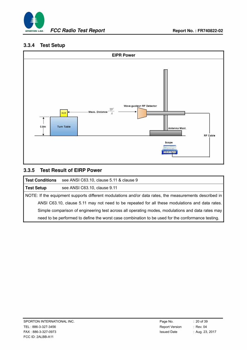
3.3.4 Test Setup
EIPR Power
3.3.5 Test Result of EIRP Power
Test Conditions see ANSI C63.10, clause 5.11 & clause 9
Test Setup see ANSI C63.10, clause 9.11
NOTE: If the equipment supports different modulations and/or data rates, the measurements described in
ANSI C63.10, clause 5.11 may not need to be repeated for all these modulations and data rates.
Simple comparison of engineering test across all operating modes, modulations and data rates may
need to be performed to define the worst case combination to be used for the conformance testing.
FCC Radio Test Report Report No. : FR740822-02
SPORTON INTERNATIONAL INC. Page No. : 21 of 39
TEL : 886-3-327-3456 Report Version : Rev. 04
FAX : 886-3-327-0973 Issued Date : Aug. 23, 2017
FCC ID: 2ALBB-A11
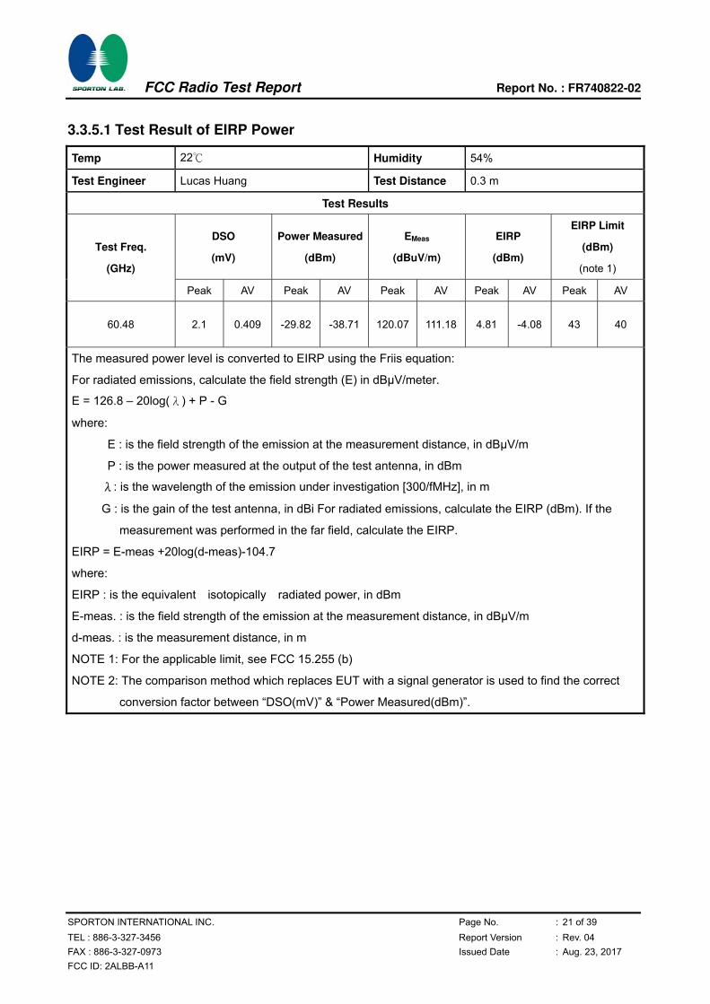
3.3.5.1 Test Result of EIRP Power
Temp 22℃ Humidity 54%
Test Engineer Lucas Huang Test Distance 0.3 m
Test Results
DSO
(mV)
Power Measured
(dBm)
EMeas
(dBuV/m)
EIRP
(dBm)
EIRP Limit
(dBm)
(note 1)
Test Freq.
(GHz)
Peak AV Peak AV Peak AV Peak AV Peak AV
60.48 2.1 0.409 -29.82 -38.71 120.07 111.18 4.81 -4.08 43 40
The measured power level is converted to EIRP using the Friis equation:
For radiated emissions, calculate the field strength (E) in dBµV/meter.
E = 126.8 – 20log(λ) + P - G
where:
E : is the field strength of the emission at the measurement distance, in dB V/m
P : is the power measured at the output of the test antenna, in dBm
λ: is the wavelength of the emission under investigation [300/fMHz], in m
G : is the gain of the test antenna, in dBi For radiated emissions, calculate the EIRP (dBm). If the
measurement was performed in the far field, calculate the EIRP.
EIRP = E-meas +20log(d-meas)-104.7
where:
EIRP : is the equivalent isotopically radiated power, in dBm
E-meas. : is the field strength of the emission at the measurement distance, in dB V/m
d-meas. : is the measurement distance, in m
NOTE 1: For the applicable limit, see FCC 15.255 (b)
NOTE 2: The comparison method which replaces EUT with a signal generator is used to find the correct
conversion factor between “DSO(mV)” & “Power Measured(dBm)”.
FCC Radio Test Report Report No. : FR740822-02
SPORTON INTERNATIONAL INC. Page No. : 22 of 39
TEL : 886-3-327-3456 Report Version : Rev. 04
FAX : 886-3-327-0973 Issued Date : Aug. 23, 2017
FCC ID: 2ALBB-A11
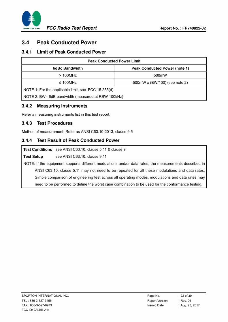
3.4 Peak Conducted Power
3.4.1 Limit of Peak Conducted Power
Peak Conducted Power Limit
6dBc Bandwidth Peak Conducted Power (note 1)
> 100MHz 500mW
≤ 100MHz 500mW x (BW/100) (see note 2)
NOTE 1: For the applicable limit, see FCC 15.255(d)
NOTE 2: BW= 6dB bandwidth (measured at RBW 100kHz)
3.4.2 Measuring Instruments
Refer a measuring instruments list in this test report.
3.4.3 Test Procedures
Method of measurement: Refer as ANSI C63.10-2013, clause 9.5
3.4.4 Test Result of Peak Conducted Power
Test Conditions see ANSI C63.10, clause 5.11 & clause 9
Test Setup see ANSI C63.10, clause 9.11
NOTE: If the equipment supports different modulations and/or data rates, the measurements described in
ANSI C63.10, clause 5.11 may not need to be repeated for all these modulations and data rates.
Simple comparison of engineering test across all operating modes, modulations and data rates may
need to be performed to define the worst case combination to be used for the conformance testing.

FCC Radio Test Report Report No. : FR740822-02
SPORTON INTERNATIONAL INC. Page No. : 23 of 39
TEL : 886-3-327-3456 Report Version : Rev. 04
FAX : 886-3-327-0973 Issued Date : Aug. 23, 2017
FCC ID: 2ALBB-A11
3.4.4.1 Peak Conducted Power
Temp 22℃ Humidity 54%
Test Engineer Lucas Huang
Test Date Jun. 12, 2017
Test Results
Test Freq.
(GHz) EIRP (dBm)
Max.
Ant. Gain
(dBi)
Peak Power
(dBm)
(note1)
Peak Power
(mW)
6dBc BW
(MHz)
(note2)
Peak Power
Limit (mW)
(note3)
60.48 4.81 0 4.81 3.028 0.70 3.48
NOTE 1: Because EUT used for the integral antenna without temporary RF connector provided. Therefore
peak conducted power is equal to EIRP power subtract the antenna gain.
NOTE 2: For the 6dBc bandwidth, see test report clause 3.2.5.
NOTE 3: For the applicable limit, see FCC 15.255(d)
NOTE 4: For radiated emission measurements, calculate conducted transmitter output power P(cond)(dBm)
P(cond) = EIRP - G(dBi)
where:
G(dBi) is gain of EUT antenna.

FCC Radio Test Report Report No. : FR740822-02
SPORTON INTERNATIONAL INC. Page No. : 24 of 39
TEL : 886-3-327-3456 Report Version : Rev. 04
FAX : 886-3-327-0973 Issued Date : Aug. 23, 2017
FCC ID: 2ALBB-A11
3.5 Transmitter Spurious Emissions
3.5.1 Limit of Transmitter Spurious Emissions
Frequency Range Limit
Radiated emissions below 40 GHz FCC 15.209
Radiated emissions above 40 GHz – 200GHz 90 pW/cm2 @ 3 m (Equivalent EIRP 102 W, -9.91dBm)
NOTE 1: For the applicable limit, see FCC 15.255(c)
NOTE 2: Spurious emissions shall not exceed the level of the fundamental emission.
3.5.2 Test Procedures
Method of measurement: Refer as ANSI C63.10-2013, clause 9.12
3.5.3 Test Setup
Transmitter Spurious Emissions
9kHz ~30MHz

FCC Radio Test Report Report No. : FR740822-02
SPORTON INTERNATIONAL INC. Page No. : 25 of 39
TEL : 886-3-327-3456 Report Version : Rev. 04
FAX : 886-3-327-0973 Issued Date : Aug. 23, 2017
FCC ID: 2ALBB-A11
30MHz~1GHz
1GHz ~40GHz

FCC Radio Test Report Report No. : FR740822-02
SPORTON INTERNATIONAL INC. Page No. : 26 of 39
TEL : 886-3-327-3456 Report Version : Rev. 04
FAX : 886-3-327-0973 Issued Date : Aug. 23, 2017
FCC ID: 2ALBB-A11
Above 40GHz
A measuring distance of at 3 m shall be used for measurements at frequencies up to 15 GHz. For frequencies above 15 GHz, any suitable measuring distance may be used. The measurement distance is chosen up to far field distance, depending on the test system noise floor for detecting spurious emission signals. Then above 15 GHz shall be extrapolated to the specified distance using an extrapolation factor of 20 dB/decade from spec. distance (3 m) to measurement distance. Distance extrapolation factor = 20 log (spec. distance [3 m] / measurement distance [N m]) (dB) .The measurements described in ANSI C63.10, clause 7.8.6. If the emission cannot be detected at 1 m, reduce the RBW to increase system sensitivity. Note the value. If the emission still cannot be detected, move the horn closer to the EUT, noting the distance at which a measurement is made.
3.5.4 Test Result of Transmitter Spurious Emissions
Test Conditions see ANSI C63.10, clause 5.11 & clause 9
Test Setup see ANSI C63.10, clause 9.12 9.13
NOTE: If equipment having different channel plan and nominal channel bandwidth modes (see test report
clause 1.1.1), the measurements are uninfluenced by different channel plan and nominal channel
bandwidth modes, may not need to be repeated for all modes.
3.5.4.1 Test Result of Transmitter Spurious Emissions (Below 30MHz)
All amplitude of spurious emissions that are attenuated by more than 20 dB below the permissible value has
no need to be reported.
FCC Radio Test Report Report No. : FR740822-02
SPORTON INTERNATIONAL INC. Page No. : 27 of 39
TEL : 886-3-327-3456 Report Version : Rev. 04
FAX : 886-3-327-0973 Issued Date : Aug. 23, 2017
FCC ID: 2ALBB-A11
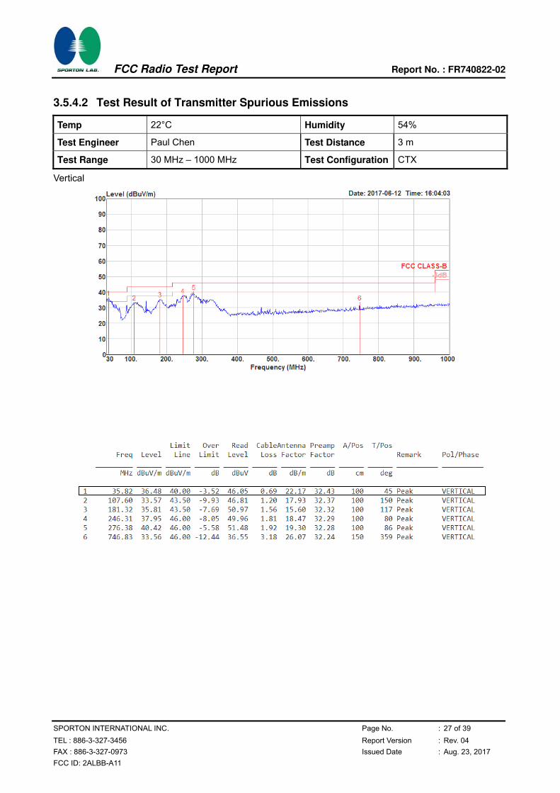
3.5.4.2 Test Result of Transmitter Spurious Emissions
Temp 22°C Humidity 54%
Test Engineer Paul Chen Test Distance 3 m
Test Range 30 MHz – 1000 MHz Test Configuration CTX
Vertical
FCC Radio Test Report Report No. : FR740822-02
SPORTON INTERNATIONAL INC. Page No. : 28 of 39
TEL : 886-3-327-3456 Report Version : Rev. 04
FAX : 886-3-327-0973 Issued Date : Aug. 23, 2017
FCC ID: 2ALBB-A11
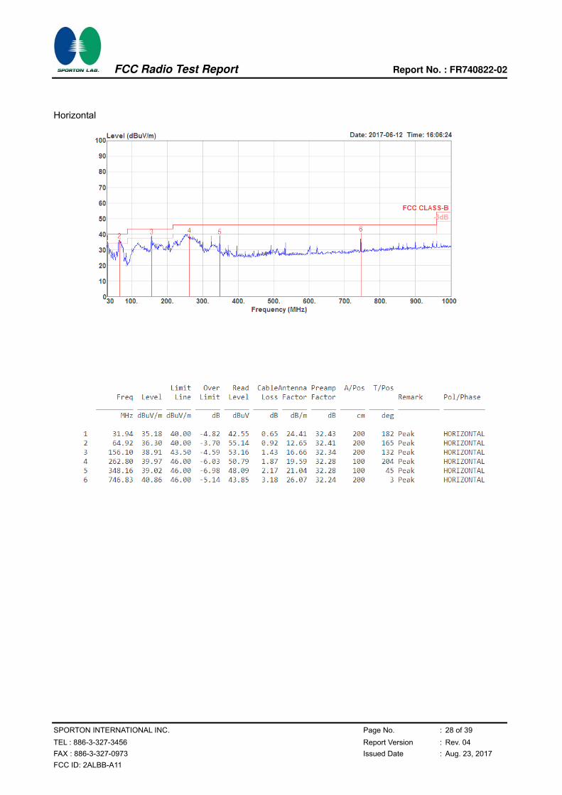
Horizontal
FCC Radio Test Report Report No. : FR740822-02
SPORTON INTERNATIONAL INC. Page No. : 29 of 39
TEL : 886-3-327-3456 Report Version : Rev. 04
FAX : 886-3-327-0973 Issued Date : Aug. 23, 2017
FCC ID: 2ALBB-A11
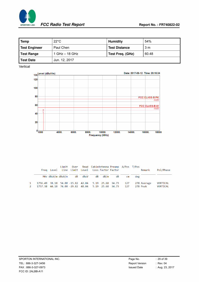
Temp 22°C Humidity 54%
Test Engineer Paul Chen Test Distance 3 m
Test Range 1 GHz – 18 GHz Test Freq. (GHz) 60.48
Test Date Jun. 12, 2017
Vertical

FCC Radio Test Report Report No. : FR740822-02
SPORTON INTERNATIONAL INC. Page No. : 30 of 39
TEL : 886-3-327-3456 Report Version : Rev. 04
FAX : 886-3-327-0973 Issued Date : Aug. 23, 2017
FCC ID: 2ALBB-A11
Horizontal
FCC Radio Test Report Report No. : FR740822-02
SPORTON INTERNATIONAL INC. Page No. : 31 of 39
TEL : 886-3-327-3456 Report Version : Rev. 04
FAX : 886-3-327-0973 Issued Date : Aug. 23, 2017
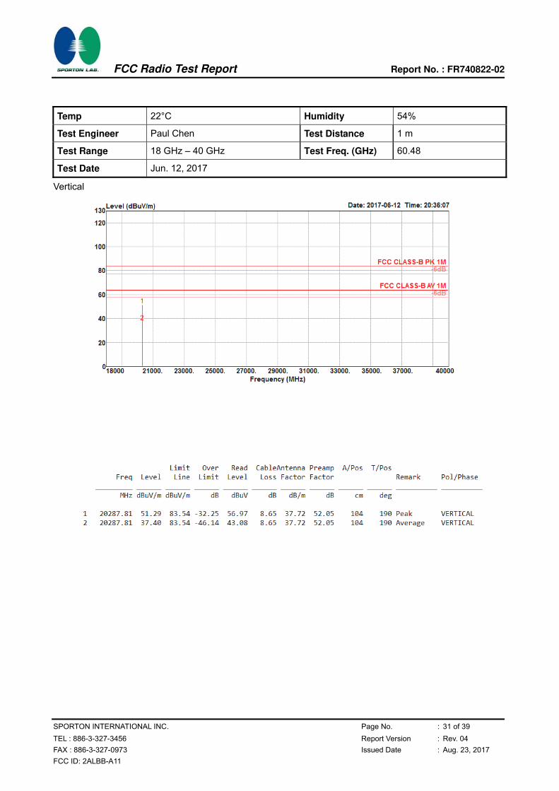
FCC ID: 2ALBB-A11
Temp 22°C Humidity 54%
Test Engineer Paul Chen Test Distance 1 m
Test Range 18 GHz – 40 GHz Test Freq. (GHz) 60.48
Test Date Jun. 12, 2017
Vertical
FCC Radio Test Report Report No. : FR740822-02
SPORTON INTERNATIONAL INC. Page No. : 32 of 39
TEL : 886-3-327-3456 Report Version : Rev. 04
FAX : 886-3-327-0973 Issued Date : Aug. 23, 2017
FCC ID: 2ALBB-A11
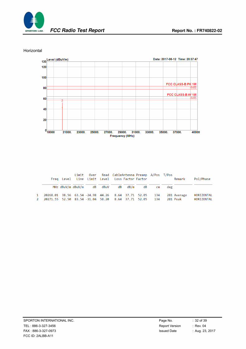
Horizontal
FCC Radio Test Report Report No. : FR740822-02
SPORTON INTERNATIONAL INC. Page No. : 33 of 39
TEL : 886-3-327-3456 Report Version : Rev. 04
FAX : 886-3-327-0973 Issued Date : Aug. 23, 2017
FCC ID: 2ALBB-A11
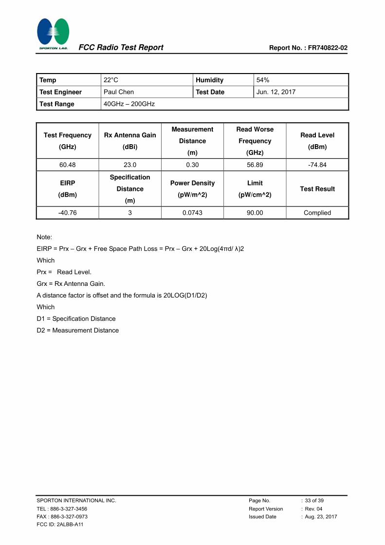
Temp 22°C Humidity 54%
Test Engineer Paul Chen Test Date Jun. 12, 2017
Test Range 40GHz – 200GHz
Test Frequency
(GHz)
Rx Antenna Gain
(dBi)
Measurement
Distance
(m)
Read Worse
Frequency
(GHz)
Read Level
(dBm)
60.48 23.0 0.30 56.89 -74.84
EIRP
(dBm)
Specification
Distance
(m)
Power Density
(pW/m^2)
Limit
(pW/cm^2) Test Result
-40.76 3 0.0743 90.00 Complied
Note:
EIRP = Prx – Grx + Free Space Path Loss = Prx – Grx + 20Log(4πd/ )2
Which
Prx = Read Level.
Grx = Rx Antenna Gain.
A distance factor is offset and the formula is 20LOG(D1/D2)
Which
D1 = Specification Distance
D2 = Measurement Distance
FCC Radio Test Report Report No. : FR740822-02
SPORTON INTERNATIONAL INC. Page No. : 34 of 39
TEL : 886-3-327-3456 Report Version : Rev. 04
FAX : 886-3-327-0973 Issued Date : Aug. 23, 2017
FCC ID: 2ALBB-A11
3.6 Frequency Stability
3.6.1 Limit of Frequency Stability
Frequency Stability Limit
Refer as FCC 15.255(e) and
ANSI C63.10-2013, clause 9.14 within the frequency bands
Note: These measurements shall also be performed at normal and extreme test conditions.
3.6.2 Measuring Instruments
Refer a measuring instruments list in this test report.
3.6.3 Test Procedures
Method of measurement: Refer as ANSI C63.10-2013, clauses 9.14.
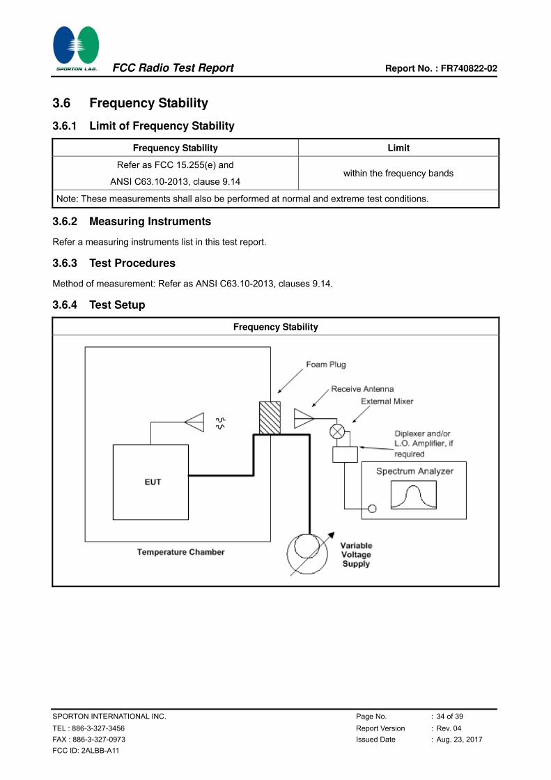
3.6.4 Test Setup
Frequency Stability

FCC Radio Test Report Report No. : FR740822-02
SPORTON INTERNATIONAL INC. Page No. : 35 of 39
TEL : 886-3-327-3456 Report Version : Rev. 04
FAX : 886-3-327-0973 Issued Date : Aug. 23, 2017
FCC ID: 2ALBB-A11
3.6.5 Test Result of Frequency Stability
Test Conditions see ANSI C63.10, clause 5.11 & clause 9
Test Setup see ANSI C63.10, clause 9.14
NOTE: If equipment having different channel plan and nominal channel bandwidth modes (see test report
clause 1.1.1), the measurements are uninfluenced by different channel plan and nominal channel
bandwidth modes, may not need to be repeated for all modes.
3.6.5.1 Frequency Stability with Respect to Ambient Temperature
Frequency Stability with Respect to Ambient Temperature
Temp 22℃ Humidity 54%
Test Engineer Lucas Huang Test Date Jun. 12, 2017
Test Results
Test Temperature (°C) Measured Frequency
(MHz)
Delta Frequency
(kHz)
Limit
(±kHz)
-10 60479.3341 -8.80 within band
0 60479.3334 -9.50 within band
10 60479.3245 -18.40 within band
20 60479.3429 Reference within band
30 60479.3421 -0.80 within band
40 60479.3368 -6.10 within band
50 60479.3327 -10.20 within band
55 60479.3347 -8.20 within band
NOTE: The manufacturer’s specified temperature range of -10 to 55°C.
3.6.5.2 Frequency Stability When Varying Supply Voltage
Frequency Stability When Varying Supply Voltage
Temp 22℃ Humidity 54%
Test Engineer Paul Chen Test Date Jun. 12, 2017
Test Results
Test Voltage: (Vdc) Measured Frequency
(MHz)
Delta Frequency
(kHz)
Limit
(±kHz)
93.5 60479.3431 0.20 within band
110 60479.3429 Reference within band
126.5 60479.3499 7.00 within band
FCC Radio Test Report Report No. : FR740822-02
SPORTON INTERNATIONAL INC. Page No. : 36 of 39
TEL : 886-3-327-3456 Report Version : Rev. 04
FAX : 886-3-327-0973 Issued Date : Aug. 23, 2017
FCC ID: 2ALBB-A11
3.7 Operation Restriction and Group Installation
3.7.1 Limit of Operation Restriction and Group Installation
Item Limit
Operation Restriction
Operation is not permitted for the following products:
Equipment used on aircraft or satellites. (Refer as FCC 15.255 (a))
Field disturbance sensors, including vehicle radar systems, unless the field
disturbance sensors are employed for fixed operation. (Refer as FCC
15.255 (a))
Group Installation Operation is not permitted for the following products:
External phase-locking (Refer as FCC 15.255(g))
3.7.2 Result of Operation Restriction
Manufacturer declares that EUT will not been used on aircraft or satellites. Then user manual will include a
statement to caution EUT is not permitted for used on aircraft or satellites. EUT is a wireless video area
network (WVAN) for the connection of consumer electronic (CE) audio and video devices.
3.7.3 Result of Group Installation
The frequency, amplitude and phase of the transmit signal are set within the EUT. There are no external
phase-locking inputs or any other means of combining two or more units together to realize a beam-forming
array.

FCC Radio Test Report Report No. : FR740822-02
SPORTON INTERNATIONAL INC. Page No. : 37 of 39
TEL : 886-3-327-3456 Report Version : Rev. 04
FAX : 886-3-327-0973 Issued Date : Aug. 23, 2017
FCC ID: 2ALBB-A11
4 Test Equipment and Calibration Data
Instrument Manufacturer Model No. Serial No. Characteristics Calibration
Date Remark
AC Power Source ChainTek APC-1000W N/A N/A N/A Conduction (CO05-HY)
EMI Test Receiver Rohde & Schwarz
ESCI 7 100724 9kHz~7GHz Aug. 30, 2016 Conduction (CO05-HY)
Hygrometer Testo 608-H1 34913912 N/A May 02, 2017 Conduction (CO05-HY)
LISN Rohde & Schwarz
ENV216 100080 9kHz~30MHz Nov. 29, 2016 Conduction (CO05-HY)
LF Cable HUBER + SUHNER
RG-214/U LF01 N/A Jan. 05, 2017 Conduction (CO05-HY)
Pulse Limiter Rohde & Schwarz
ESH3-Z2 100851 N/A Jan. 05, 2017 Conduction (CO05-HY)
Loop Antenna Teseq HLA 6120 24155 9kHz - 30 MHz Mar. 16, 2016* Radiation
(03CH01-CB)
BILOG ANTENNA with 6dB
Attenuator TESEQ & EMCI CBL6112D & N-6-06
37880 & AT-N0609
20MHz ~ 2GHz Aug. 30, 2016 Radiation
(03CH01-CB)
Horn Antenna EMCO 3115 00075790 750MHz ~ 18GHz Nov. 10, 2016 Radiation
(03CH01-CB)
Horn Antenna Schwarzbeck BBHA 9170 BBHA9170252 15GHz ~ 40GHz Jul. 25, 2016 Radiation
(03CH01-CB)
Pre-Amplifier EMCI EMC330N 980332 20MHz ~ 3GHz May 02, 2017 Radiation
(03CH01-CB)
Pre-Amplifier Agilent 8449B 3008A02310 1GHz ~ 26.5GHz Jan. 16, 2017 Radiation
(03CH01-CB)
Pre-Amplifier MITEQ TTA1840-35-HG 1864479 18GHz ~ 40GHz Jun. 28, 2016 Radiation
(03CH01-CB)
Spectrum Analyzer
R&S FSP40 100056 9kHz ~ 40GHz Nov. 22, 2016 Radiation
(03CH01-CB)
EMI Test R&S ESCS 100355 9kHz ~ 2.75GHz May 06, 2017 Radiation
(03CH01-CB)
RF Cable-low Woken Low Cable-16+17 N/A 30 MHz ~ 1 GHz Oct. 24, 2016 Radiation
(03CH01-CB)
RF Cable-high Woken High Cable-16 N/A 1 GHz ~ 18 GHz Oct. 24, 2016 Radiation
(03CH01-CB)
RF Cable-high Woken High Cable-16+17 N/A 1 GHz ~ 18 GHz Oct. 24, 2016 Radiation
(03CH01-CB)
RF Cable-high Woken High Cable-40G#1 N/A 18GHz ~ 40 GHz Oct. 24, 2016 Radiation
(03CH01-CB)
RF Cable-high Woken High Cable-40G#2 N/A 18GHz ~ 40 GHz Oct. 24, 2016 Radiation
(03CH01-CB)
Test Software Audix E3 6.2009-l0-7 N/A N/A Radiation
(03CH01-CB)
*Mixer OML M19HW/A U91113-1 40 ~ 60 GHz Sep. 09, 2015 Radiation
(03CH01-CB)
*Mixer OML M15HW/A V91113-1 50 ~ 75 GHz Sep. 14, 2015 Radiation
(03CH01-CB)
*Mixer OML M12HW/A E91113-1 60 ~ 90 GHz Sep. 17, 2015 Radiation
(03CH01-CB)

FCC Radio Test Report Report No. : FR740822-02
SPORTON INTERNATIONAL INC. Page No. : 38 of 39
TEL : 886-3-327-3456 Report Version : Rev. 04
FAX : 886-3-327-0973 Issued Date : Aug. 23, 2017
FCC ID: 2ALBB-A11
Instrument Manufacturer Model No. Serial No. Characteristics Calibration
Date Remark
*Mixer OML M08HW/A F91113-1 90 ~ 140 GHz Sep. 21, 2015 Radiation
(03CH01-CB)
*Mixer OML M05HW/A G91113-1 140 ~ 220 GHz Sep. 24, 2015 Radiation
(03CH01-CB)
*Detector Millitech DET-15-RPFW0 #A16473(038) 50 ~ 75 GHz Dec. 29, 2015 Radiation
(03CH01-CB)
Pico Scope Pico Pico Scope 6402C CX372/002 N/A Jul. 06, 2016 Radiation
(03CH01-CB)
*Standard Horn Antenna
Custom Microwave
M19RH U91113-A 40 ~ 60 GHz Sep. 09, 2015 Radiation
(03CH01-CB)
*Standard Horn Antenna
Custom Microwave
M15RH V91113-A 50 ~ 75 GHz Sep. 14, 2015 Radiation
(03CH01-CB)
*Standard Horn Antenna
Custom Microwave
M12RH E91113-A 60 ~ 90 GHz Sep. 17, 2015 Radiation
(03CH01-CB))
*Standard Horn Antenna
Custom Microwave
M08RH F91113-A 90 ~ 140 GHz Sep. 21, 2015 Radiation
(03CH01-CB)
*Standard Horn Antenna
Custom Microwave
M05RH G91113-A 140 ~ 220 GHz Sep. 24, 2015 Radiation
(03CH01-CB)
Temp. and Humidity Chamber
Ten Billion TTH-C2SP TBN-1010206 -20~150 degree Mar. 08. 2017 Conducted (TH01-CB)
Low Pass Filter EMEC LPF-24-200-40 S/N-001 24MHz below
pass Oct. 24, 2016
Conducted (TH01-CB)
Note: Calibration Interval of instruments listed above is one year. “*” Calibration Interval of instruments listed above is two years. N.C.R. means Non-Calibration required.

FCC Radio Test Report Report No. : FR740822-02
SPORTON INTERNATIONAL INC. Page No. : 39 of 39
TEL : 886-3-327-3456 Report Version : Rev. 04
FAX : 886-3-327-0973 Issued Date : Aug. 23, 2017
FCC ID: 2ALBB-A11
5 Measurement Uncertainty
Test Items Uncertainty Remark
Conducted Emission (150kHz ~ 30MHz) 2.7dB Confidence levels of 95%
Radiated Emission (30MHz ~ 1,000MHz) 3.6 dB Confidence levels of 95%
Radiated Emission (1GHz ~ 18GHz) 3.7 dB Confidence levels of 95%
Radiated Emission (18GHz ~ 40GHz) 3.5 dB Confidence levels of 95%
Radiated Emission (40GHz ~ 220GHz) 4.7 dB Confidence levels of 95%
Temperature 0.7°C Confidence levels of 95%