Embed Size (px)
Citation preview

Installation, Operation and Maintenance Manual
Control Display Unit
CDU-IOM-02
Rev 1.0


Installation, Operation and Maintenance Manual
Control Display Unit (CDU)
CDU-IOM-02Rev 1.0

Copyright © 2006 OuterLink Corporation All rights reserved. No part of this documentation may be reproduced in any form or by any means or used to make any derivative work (such as translation, transformation, or adaptation) without written permission from OuterLink Corporation.OuterLink reserves the right to revise this documentation and to make any changes in content from time to time without obligation on the part of OuterLink Corporation to provide notification of such revision or change. OuterLink Corporation provides this documentation without warranty, term, or condition of any kind, either implied or expressed, including, but not limited to, the implied warranties, terms or conditions of merchantability, satisfactory quality, and fitness for a particular purpose. OuterLink Corporation may make improvements or changes in the product(s) and/or the program(s) described in this documentation at any time. The OuterLink logo is a servicemark of OuterLink Corporation. All other product or service names are the property of their respective owners.

CONTENTS
PrefaceUsing OuterLink Electronic Documents . . . . . . . . . . . . . . . . . . . . . . . . . . . . . . . . xiiGuide Conventions . . . . . . . . . . . . . . . . . . . . . . . . . . . . . . . . . . . . . . . . . . . . . . . . xivRelated Product Documentation . . . . . . . . . . . . . . . . . . . . . . . . . . . . . . . . . . . . . . xvRevision History . . . . . . . . . . . . . . . . . . . . . . . . . . . . . . . . . . . . . . . . . . . . . . . . . . xvi
Chapter 1 IntroductionCDU Overview . . . . . . . . . . . . . . . . . . . . . . . . . . . . . . . . . . . . . . . . . . . . . . . . . . . . 2
CDU Controls . . . . . . . . . . . . . . . . . . . . . . . . . . . . . . . . . . . . . . . . . . . . . . . . . . . 2
Chapter 2 InstallationInstalling the CDU . . . . . . . . . . . . . . . . . . . . . . . . . . . . . . . . . . . . . . . . . . . . . . . . . . 6
CDU Installation Procedure . . . . . . . . . . . . . . . . . . . . . . . . . . . . . . . . . . . . . . . . 6CDU Test and Checkout Procedure . . . . . . . . . . . . . . . . . . . . . . . . . . . . . . . . . . 8
Arm Test and Checkout Procedure . . . . . . . . . . . . . . . . . . . . . . . . . . . . . . . 8Mayday Test and Checkout Procedure . . . . . . . . . . . . . . . . . . . . . . . . . . . . 8Shutdown Test and Checkout Procedure . . . . . . . . . . . . . . . . . . . . . . . . . . . 8Display Control Test and Checkout Procedure . . . . . . . . . . . . . . . . . . . . . . 8CDU Interference Check . . . . . . . . . . . . . . . . . . . . . . . . . . . . . . . . . . . . . . . 8
Chapter 3 OperationOperations of the CDU . . . . . . . . . . . . . . . . . . . . . . . . . . . . . . . . . . . . . . . . . . . . . 10
Power Up Operation . . . . . . . . . . . . . . . . . . . . . . . . . . . . . . . . . . . . . . . . . . . . . 10Arm Operation . . . . . . . . . . . . . . . . . . . . . . . . . . . . . . . . . . . . . . . . . . . . . . . . . 10Flight Plan Operation . . . . . . . . . . . . . . . . . . . . . . . . . . . . . . . . . . . . . . . . . . . . 10Two-way Text Messaging Operation . . . . . . . . . . . . . . . . . . . . . . . . . . . . . . . . 11
Sending a Text Message . . . . . . . . . . . . . . . . . . . . . . . . . . . . . . . . . . . . . . 11Reading a Text Message . . . . . . . . . . . . . . . . . . . . . . . . . . . . . . . . . . . . . . 11
Current Position Report Operation . . . . . . . . . . . . . . . . . . . . . . . . . . . . . . . . . . 12CDU Display Brightness Operation . . . . . . . . . . . . . . . . . . . . . . . . . . . . . . . . . 12Shutdown Operation . . . . . . . . . . . . . . . . . . . . . . . . . . . . . . . . . . . . . . . . . . . . . 12Mayday Operation . . . . . . . . . . . . . . . . . . . . . . . . . . . . . . . . . . . . . . . . . . . . . . 12Status Normal Operation . . . . . . . . . . . . . . . . . . . . . . . . . . . . . . . . . . . . . . . . . 13
Chapter 4 MaintenanceMaintaining the CDU . . . . . . . . . . . . . . . . . . . . . . . . . . . . . . . . . . . . . . . . . . . . . . . 16
Inspection of the CDU . . . . . . . . . . . . . . . . . . . . . . . . . . . . . . . . . . . . . . . . . . . . 16Troubleshooting the CDU . . . . . . . . . . . . . . . . . . . . . . . . . . . . . . . . . . . . . . . . . 16
CDU Installation, Operation and Maintenance Manual v

Contents
Appendix A SpecificationsCDU Specifications . . . . . . . . . . . . . . . . . . . . . . . . . . . . . . . . . . . . . . . . . . . . . . . . 18Technical Support . . . . . . . . . . . . . . . . . . . . . . . . . . . . . . . . . . . . . . . . . . . . . . . . . 19
Index . . . . . . . . . . . . . . . . . . . . . . . . . . . . . . . . . . . . . . . . . . . . . . . . . . . . . . . . . . 21
vi CDU Installation, Operation and Maintenance Manual

LIST OF FIGURES
1 CDU Relation to CommTrack System. . . . . . . . . . . . . . . . . . . . . . . . . . . . . . 22 CDU Controls . . . . . . . . . . . . . . . . . . . . . . . . . . . . . . . . . . . . . . . . . . . . . . . . 23 CDU Rear Panel . . . . . . . . . . . . . . . . . . . . . . . . . . . . . . . . . . . . . . . . . . . . . . 64 CDU Outline Drawing . . . . . . . . . . . . . . . . . . . . . . . . . . . . . . . . . . . . . . . . . . 75 CDU Front Panel PWR Button and Dzus Fasteners . . . . . . . . . . . . . . . . . . . 76 CDU Front Panel . . . . . . . . . . . . . . . . . . . . . . . . . . . . . . . . . . . . . . . . . . . . . 10
CDU Installation, Operation and Maintenance Manual vii

List of Figures
viii CDU Installation, Operation and Maintenance Manual

LIST OF TABLES
1 Navigating Within a PDF Document . . . . . . . . . . . . . . . . . . . . . . . . . . . . . . xii2 OuterLink Documentation Set . . . . . . . . . . . . . . . . . . . . . . . . . . . . . . . . . . . xv3 CDU Installation, Operation and Maintenance Manual Revision History . xvi4 CDU Controls . . . . . . . . . . . . . . . . . . . . . . . . . . . . . . . . . . . . . . . . . . . . . . . . 35 CDU 9-Pin DB Connector Pins . . . . . . . . . . . . . . . . . . . . . . . . . . . . . . . . . . . 66 Troubleshooting Matrix . . . . . . . . . . . . . . . . . . . . . . . . . . . . . . . . . . . . . . . . 167 CDU Specifications . . . . . . . . . . . . . . . . . . . . . . . . . . . . . . . . . . . . . . . . . . . 18
CDU Installation, Operation and Maintenance Manual ix

List of Tables
x CDU Installation, Operation and Maintenance Manual
Preface
This manual provides information about the Control Display Unit (CDU).
This document is for the CDU user and installer. This document contains information on the CDU hardware.
The manual is divided into the following topics:
� Introduction � Installation � Operation � Maintenance� Specifications
CDU Installation, Operation and Maintenance Manual xi

Preface
Using OuterLink Electronic Documents
OuterLink Corporation electronic documents are provided as PDF files. Open and view them using the Adobe® Acrobat® Reader application, version 3.0 or later. If necessary, download the Acrobat Reader from the Adobe Systems, Inc. web site:
http://www.adobe.com/prodindex/acrobat/readstep.html
Each provided PDF file offers several ways for moving among the document�s pages, as follows:
To move quickly from section to section within the document, use the Acrobat bookmarks that appear on the left side of the Acrobat Reader window. The bookmarks provide an expandable outline view of the document�s contents. To display the document�s Acrobat bookmarks, press the �Display both bookmarks and page� button on the Acrobat Reader tool bar.
To move to the referenced page of an entry in the document�s Contents or Index, click on the entry itself, each of which is hyperlinked.
To follow a cross-reference to a heading, figure, or table, click the blue text.
To move to the beginning or end of the document, to move page by page within the document, or to navigate among the pages you displayed by clicking on hyperlinks, use the Acrobat Reader navigation buttons shown in this figure:
Table 1 summarizes how to navigate within a OuterLink Corporation electronic document.
Table 1 Navigating Within a PDF Document
To Navigate This Way Click This
Move from section to section within the document.
A bookmark on the left side of the Acrobat Reader window.
Move to an entry in the Table of Contents.
The entry itself.
Move to an entry in the Index. The page number.
Move to an entry in the List of Figures or List of Tables.
The Figure or Table number.
Follow a cross-reference (highlighted in blue text).
The cross-reference text.
Move page by page. The appropriate Acrobat Reader navigation buttons.
Move to the beginning or end of the document.
The appropriate Acrobat Reader navigation buttons.
Beginning of document End of document
Next pagePrevious page
Previous or next hyperlink
xii CDU Installation, Operation and Maintenance Manual

Preface
Move backward or forward among a series of hyperlinks you have selected.
The appropriate Acrobat Reader navigation buttons.
Table 1 Navigating Within a PDF Document (continued)
To Navigate This Way Click This
CDU Installation, Operation and Maintenance Manual xiii

Preface
Guide Conventions The following visual elements are used throughout this manual, where applicable:
WARNING: Provide information that can help prevent potential fatal or serious injury to a user.
CAUTION: Provide information that can help prevent damage to equipment or the environment.
NOTE: Provide information of special importance.
xiv CDU Installation, Operation and Maintenance Manual

Preface
Related Product Documentation
Table 2 lists the OuterLink documentation set.
Table 2 OuterLink Documentation Set
Document Name Purpose Document Number
CommTrack Suite 2007User Manual
Describes the basic use and operation of the OuterLink software suite including: • CommTrack (graphical display) • CommText (text display) • CommFigure (mission analysis) • CommSpeak (voice/text display)• CommSpeak Hub (interface to CommCenter, track and voice
databases)
CTS-UM
CommTrack Suite 2007Installation Manual
Provides instructions for the installation of the CommTrack software suite.
CTS-IM
CommCenter User Manual Provides instructions for the service of the CommCenter software suite.
CC-UM
CP-3i Installation, Operation and Maintenance Manual
Provides instructions for the installation, operation and maintenance of the CP-3i hardware.
CP3i-IOM-AC
CP-4i Installation, Operation and Maintenance Manual
Provides instructions for the installation, operation and maintenance of the CP-4i hardware.
CP4i-IOM-VE
CDU Installation, Operation and Maintenance Manual
Describes the installation, operation and maintenance of the Control Display Unit (CDU).
CDU-IOM-02
OCP Installation, Operation and Maintenance Manual
Describes the installation, operation and maintenance of the OuterLink Control Panel (OCP).
OCP-IOM-01
OVP Installation, Operation and Maintenance Manual
Describes the installation, operation and maintenance of the OuterLink Voice Panel (OVP).
OVP-IOM-01
VMU Installation, Operation and Maintenance Manual
Describes the installation, operation and maintenance of the Voice Messaging Unit (VMU).
VMU-IOM-01
KDU Installation, Operation and Maintenance Manual
Describes the installation, operation and maintenance of the Keyboard Display Unit (KDU).
KDU-IOM-01
CDU Installation, Operation and Maintenance Manual xv
Preface
Revision History Table 3 shows the revision history for this manual, providing a description of the changes.
Table 3 CDU Installation, Operation and Maintenance Manual Revision History
Revision Change
1.0 New document
xvi CDU Installation, Operation and Maintenance Manual
Chapter 1
Introduction
This chapter provides an introduction to the Control Display Unit (CDU). The following topics are covered:
� CDU Overview
CDU Installation, Operation and Maintenance Manual 1

Introduction
CDU Overview The Control Display Unit (CDU) generates and receives both preprogrammed and manually entered text messages while in communication with the flight operations center. The CDU features one (1) RS-232 serial data port. It is an optional device to the OuterLink Satcom System. It is designed to operate in conjunction with the CommPoint devices (CP-3i), as well as, the CommTrack / CommText software applications. Theses software applications are used by the flight operators to follow the flight, monitor the aircraft's current status, and conduct messaging sessions.
Figure 1 shows the CDU in relation to the major components of the CommTrack System.
Figure 1 CDU Relation to CommTrack System
CDU Controls Figure 2 shows the controls of the CDU.
Figure 2 CDU ControlsTable 4 describes the basic function of each button and the LCD. Refer to �Operations of the CDU� on page 10 for button operations.
Inside Aircraft
Tx/Rx
CDU
Satellite
CP-3i
CommCenter
CommTrack Suite 2007
MENU Button
XMIT Button
MAYDAY Button
LCD Display
ENTER Button
NEXT Button
PWR Button
2 CDU Installation, Operation and Maintenance Manual

Introduction
Table 4 CDU Controls
Item Function
ENTER Button Used to select menu options and to enter text messages.
NEXT Button Used to step between selections.
MENU Button Used to sequence through menu selections.
XMIT Button Used to transmit messages.
MAYDAY Button Used to activate an emergency message in conjunction with the XMIT Button.
LCD Display Displays the various menu selections, as well as generated and received messages.
PWR Button Powers up the CDU.
CDU Installation, Operation and Maintenance Manual 3

Introduction
4 CDU Installation, Operation and Maintenance Manual

Chapter 2
This chapter provides information on CDU installation The following topics are covered:
� Installing the CDU
Installation
CDU Installation, Operation and Maintenance Manual 5

Installation
Installing the CDU This section covers the installation of the CDU.
CDU Installation Procedure
1. Connect and tighten the 9-Pin cable to the 9-Pin �D� type connector located on the rear of the CDU. Refer to Figure 3 for the location of the 9-Pin connector.
Figure 3 CDU Rear PanelFor connector pins outs, refer to Table 5.
Table 5 CDU 9-Pin DB Connector Pins
Pin Name
1 Annunciator
2 Receive Data RxD (In)
3 Transmit Data TxD (Out)
4 Spare
5 Ground
6 + 28VDC Power Input
7 + 28VDC Power Input
8 Power Ground
9 Power Ground
9-Pin Serial Connector with two (2) screws
6 CDU Installation, Operation and Maintenance Manual

Installation
2. Ensure there is enough space to mount the CDU. Refer to Figure 4.
Figure 4 CDU Outline Drawing3. Install the CDU into the rack and turn the four (4) Dzus fasteners located on the
front of the CDU until they lock. Refer to Figure 5. 4. Press the PWR button. At first, the LCD displays the CDU firmware version during
initialization. Once this link is established, the LCD displays READY. READY indicates the CDU is communicating with the CP-3i and is operational. Refer to Figure 5.
Figure 5 CDU Front Panel PWR Button and Dzus Fasteners
Dzus Fasteners
PWR Button
Dzus Fasteners
CDU Installation, Operation and Maintenance Manual 7

Installation
CDU Test and Checkout Procedure
Once the CDU is installed, we recommend the following tests to check its functionality.
NOTE: CommTrack Suite 2007 needs to be installed, configured and operational for this test.
Arm Test and Checkout Procedure
This procedure tests the �ARM� function.
1. Select the Menu item �ARM�.2. Press �XMIT�. The �ARM� message should be sent to the dispatched. Receipt of
the message at the Dispatcher Base Station should be automatically acknowledged. This �ACK� should be displayed on the CDU�s display.
Mayday Test and Checkout Procedure
This procedure test the �MAYDAY� function.
1. Depress the "MAYDAY" key.2. The display asks: "SEND MAYDAY ?"3. If this is what you want, press the "XMIT" key.
NOTE: This two-step process is used to reduce the probability of inadvertent false alarms.
4. CDU displays "WAITING FOR ACK�. 5. MAYDAY messages are automatically transmitted and generates an automatic
"MAYDAY ACK" message back to the aircraft.6. The "MAYDAY ACK" message is continuously displayed on the CDU until the pilot
selects either the "MENU" key or the "NEXT" key. 7. The CDU remains in the Mayday state until successfully cleared by flight
operations with the Mayday Disable message, while reporting. 8. The CDU displays "MAYDAY CLEARED", advising the pilot that Dispatch has
cleared the Mayday state.
Shutdown Test and Checkout Procedure
This procedure tests the �SHUTDOWN� function.
1. Select the Menu item �SHUTDOWN�.2. Press �XMIT�. The �SHUTDOWN� message should be sent to the dispatched.
Receipt of the message at the Dispatcher Base Station should be automatically acknowledged. This �ACK� should be displayed on the CDU�s display.
Display Control Test and Checkout Procedure
This procedure tests the �DISPLAY CONTROL� function.
1. Select the Menu item �DISPLAY CONTROL�.2. Press �NEXT� to adjust the brightness of the display.
CDU Interference Check Check for possible interference with other devices.
CAUTION: Verify that the CDU does not cause interference with other cockpit displays such as VOR, LOC, GS, DME, RADAR and navigation GPS.
8 CDU Installation, Operation and Maintenance Manual

Chapter 3
This chapter provides information on using the CDU. The following topics are covered:
� Operations of the CDU
Operation
CDU Installation, Operation and Maintenance Manual 9
Operation
Operations of the CDU
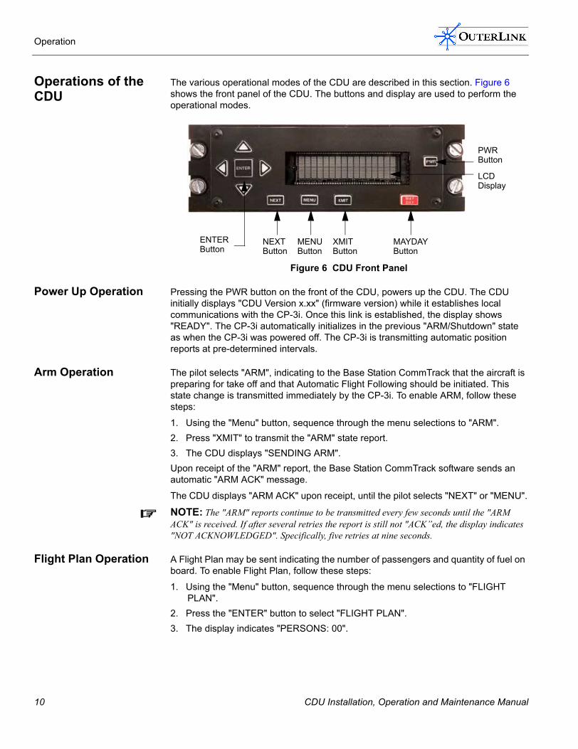
The various operational modes of the CDU are described in this section. Figure 6 shows the front panel of the CDU. The buttons and display are used to perform the operational modes.
Figure 6 CDU Front Panel
Power Up Operation Pressing the PWR button on the front of the CDU, powers up the CDU. The CDU initially displays "CDU Version x.xx" (firmware version) while it establishes local communications with the CP-3i. Once this link is established, the display shows "READY". The CP-3i automatically initializes in the previous "ARM/Shutdown" state as when the CP-3i was powered off. The CP-3i is transmitting automatic position reports at pre-determined intervals.
Arm Operation The pilot selects "ARM", indicating to the Base Station CommTrack that the aircraft is preparing for take off and that Automatic Flight Following should be initiated. This state change is transmitted immediately by the CP-3i. To enable ARM, follow these steps:
1. Using the "Menu" button, sequence through the menu selections to "ARM".2. Press "XMIT" to transmit the "ARM" state report.3. The CDU displays "SENDING ARM". Upon receipt of the "ARM" report, the Base Station CommTrack software sends an automatic "ARM ACK" message.
The CDU displays "ARM ACK" upon receipt, until the pilot selects "NEXT" or "MENU".
NOTE: The "ARM" reports continue to be transmitted every few seconds until the "ARM ACK" is received. If after several retries the report is still not "ACK�ed, the display indicates "NOT ACKNOWLEDGED". Specifically, five retries at nine seconds.
Flight Plan Operation A Flight Plan may be sent indicating the number of passengers and quantity of fuel on board. To enable Flight Plan, follow these steps:
1. Using the "Menu" button, sequence through the menu selections to "FLIGHT PLAN".
2. Press the "ENTER" button to select "FLIGHT PLAN". 3. The display indicates "PERSONS: 00".
MENU Button
XMIT Button
MAYDAY Button
LCD Display
ENTER Button
NEXT Button
PWR Button
10 CDU Installation, Operation and Maintenance Manual
Operation
4. Using the Up/Down arrows, step through 0-9 to indicate the number of passengers. Press "ENTER" to select the desired digit and move the cursor right one (1) space. The Left/Right arrows also move the cursor. Press "NEXT" to store the number of passengers and to display "FUEL: 0000".
5. Select and Enter pounds of fuel in the same manner as for Passengers.6. Press "XMIT" to transmit the Flight Plan.
NOTE: Pressing "XMIT" before "FUEL" has been selected will NOT cause a transmission.
7. CDU displays "SENDING FLT" until base station receives the flight plan.8. CDU displays "FLIGHT PLAN ACK" to indicate that the Flight Plan has been
received at the Dispatcher Base Station.
Two-way Text Messaging Operation
Two-way text messaging may be conducted with the flight operations center via the CDU and Base Station CommText software. The CDU menu contains both SEND MESSAGE and READ MESSAGE selections.
NOTE: The pilot at the controls is prohibited from composing a message in flight.
Sending a Text Message To send a text message, follow these steps:
1. Use the MENU key to select "SEND MESSAGE".2. Press "ENTER".3. The CDU displays "COMPOSE MESSAGE".4. Use the Up/Down arrows to select alphabetic or numeric characters. As each
character is selected, press "ENTER". This selects the character and moves the cursor right one (1) space. The Left/Right arrow keys can also be used to move the cursor.
5. When the complete message is entered, press "XMIT" to send the message.6. CDU displays "WAITING FOR ACK". 7. When CommText software receives the message, CDU displays "MESSAGE
RECEIVED�.
NOTE: Messages sent from the aircraft to flight operations automatically contain ID, sensor status, and position report in addition to the text message.
Reading a Text Message To read incoming text messages, follow these steps:
1. Use the MENU key to select "READ MESSAGES". Press "ENTER".2. The most recent message is displayed. If no messages have been received, the
CDU displays "NO MESSAGES".3. To read additional (previous) messages, select "NEXT".4. When the last message is displayed, if "NEXT" is pressed then the message
queue wraps, causing the most recent message to again be displayed.
CDU Installation, Operation and Maintenance Manual 11
Operation
Current Position Report Operation
The pilot may send a current position report to the flight operations center at any time, using these steps:
1. Using the "MENU" button, sequence through the menu selections to "POSITION".2. Press "XMIT" to transmit the current "POSITION" report.3. The CDU displays "SENDING POSITION".4. When the CommText software (Flight Operations) receives the report, the CDU
display changes to "POSITION ACK".
NOTE: The exact content of the detailed position report is NOT controlled by the CDU, rather it depends upon the capabilities of the GPS receiver (or other navaid) attached to the CP-3i.
CDU Display Brightness Operation
CDU display brightness can be controlled via the Display Control menu command. Follow these steps:
1. Using "MENU", select "DISPLAY CONTROL".2. Press "ENTER". 3. Using the "NEXT" key steps display brightness through four (4) levels. 4. Press "ENTER" to store the selected brightness level.
Shutdown Operation In terminating the flight, the pilot issues the Shutdown menu command, using these steps:
1. Select "SHUTDOWN" from the MENU. 2. Press "XMIT" to send the Shutdown message. 3. The display shows "SENDING SHUTDOWN" until the "Shutdown ACK" is
received.This indicates an uneventful landing and flight termination to flight operations, such that no further automatic position reports should be anticipated.
NOTE: The pilot should wait for this �ACK� before shutting off the power to the CP-3i this prevents a false alarm at Flight Operations, if the CP-3i transceiver is powered off and the automatic position reporting stops prior to Operations receiving the "SHUTDOWN" message.
Mayday Operation In the event of emergency, the pilot should activate the �MAYDAY� function on the CDU if possible, using these steps:
1. Depress the "MAYDAY" key.2. The display asks: "SEND MAYDAY ?"3. If this is what you want, press the "XMIT" key.
NOTE: This two-step process is used to reduce the probability of inadvertent false alarms.
4. CDU displays "WAITING FOR ACK�. 5. MAYDAY messages are automatically transmitted every fifteen (15) seconds,
together with GPS location updates.6. Receipt of a "MAYDAY" message triggers an alarm in the flight operations center,
indicates the Mayday situation and aircraft ID, and generates an automatic "MAYDAY ACK" message back to the aircraft.
12 CDU Installation, Operation and Maintenance Manual

Operation
7. The "MAYDAY ACK" message is continuously displayed on the CDU until the pilot selects either the "MENU" key or the "NEXT" key. The pilot can then (if desired) select "Send Message", to send text messages.
8. The CDU remains in the Mayday state until successfully cleared by flight operations with the Mayday Disable message, while reporting.
9. The CDU displays "MAYDAY CLEARED", advising the pilot that Dispatch has cleared the Mayday state.
NOTE: This MAYDAY procedure should be used, if possible, to augment your standard emergency procedures, not in place of such procedures. In particular, do NOT assume that the MAYDAY message has been visually acknowledged by flight operations. Continue to follow all standard Emergency procedures, including using voice communications as the primary mode of communications.
Status Normal Operation
The pilot may indicate that normal aircraft status has been restored, using these steps:
1. Using the "MENU" button, sequence through the menu selections to "STATUS NORMAL".
2. Press "XMIT" to transmit the "STATUS NORMAL" message.3. The CDU displays "SENDING STNORMAL".4. When the CommText software (operations) receives the message, the CDU
display changes to "STATUSNORMAL ACK".5. As with all other "ACK" displays, the pilot clears the "STATUSNORMAL ACK"
display by pressing either "NEXT" or "MENU".
CDU Installation, Operation and Maintenance Manual 13

Operation
14 CDU Installation, Operation and Maintenance Manual

Chapter 4
This chapter provides information on maintaining the CDU. The following topics are covered:
� Maintaining the CDU
Maintenance
CDU Installation, Operation and Maintenance Manual 15

Maintenance
Maintaining the CDU
This section covers maintenance and troubleshooting the CDU.
Inspection of the CDU We recommend that you inspect the device on a routine schedule. Inspect and ensure that:
� All fasteners and cable connections are tightened properly � Buttons are operational and not broken � LCD display cover is not cracked If you encounter an issue with the buttons or the LCD, please contact Technical Support.
Troubleshooting the CDU
Table 6 provides a guide to troubleshooting the CDU.
NOTE: A Digital Multimeter is recommended to assist you in troubleshooting.
Table 6 Troubleshooting Matrix
Symptom Causes Solution
No power when you press the PWR button.
• Bad PC board.• Bad PWR button.• No power in aircraft.• Blown or removed fuse in aircraft.• Electrical Bus not turned on.• Faulty wiring.
• Meter the wiring.• Check the PWR
button for functionality.
• Check for blown or removed fuse.
• Swap out the faulty CDU with a known good CDU.
If LCD continues to display the CDU firmware version after initialized and does NOT display READY.
• Bad wiring between the CP-3i and the CDU.
• Not powered or faulty CP-3i. • CP-3i not configured properly.
• Check the CP-3i to ensure the Status LED is ON.
• Meter the wiring.• Swap out the faulty
CDU with a known good CDU.
16 CDU Installation, Operation and Maintenance Manual

Appendix A
This appendix provides information on the specifications for the CDU. The following topics are covered:
� CDU Specifications � Technical Support
Specifications
CDU Installation, Operation and Maintenance Manual 17

Specifications
CDU Specifications Table 7 describes the various CDU specifications.
Table 7 CDU Specifications
Specifications
Dimensions 5.75 �x 3.88� x 1.83� (WxDxH) (14.6cm x 9.9cm x 4.6cm)
Power 12 � 28VDC
Mounting Dzus
Weight 15.7 Ounces (0.44 kg)
Connector 9-Pin �D� type (RS-232 serial port data)
Display Vacuum Fluorescent (VFD), 16 Character/Row, 2 -Row, Blue-Green Color
Character Size: 2.46 x 4.76mm
Brightness Control: 100%, 75%, 50% and 25%
Environmental Operating Temperature -40° � 70°C
Storage Temperature -40° � 85°C
Relative Humidity 10 � 90% non-condensing
Altitude 25,000 Ft. (7620m) (Unpressurized)
Agency Approvals FCC CFR 47, Parts 87, Subsection D, and Technical Requirements.
FCC CFR 47, Part 15, Radio Frequency Devices, Subsection B and Unintentional Radiators
FCC Parts 15 and 2, Subsection I and J
RTCA DO-178B, Level E, firmware compliance
STCs and PMAs for various aircraft, including Bell, Eurocopter and Sikorsky
RTCA DO-160D Temperature, Section 4.5 Category B
Vibration, Section 8 Category R (Helicopter Zone 2)
Crash Safety, Section 7 Category B
Radiated and Conducted Emissions, Section 21 Category B
18 CDU Installation, Operation and Maintenance Manual

Specifications
Technical Support For additional assistance, please contact OuterLink Technical Support.
� Call us at: 978-856-0007� Fax us at: 978-856-0013� Email us at: [email protected]
CDU Installation, Operation and Maintenance Manual 19

Specifications
20 CDU Installation, Operation and Maintenance Manual

INDEX
Symbols9-Pin DB Connector Pins
CDU 6
AArm
Operation 10Test and Checkout Procedure 8
CCDU
CDU 9-Pin DB Connector Pins 6Controls 2Inspection 16Installation Procedure 6Installing 6Interference Check 8Maintenance 16Operation 10Outline Drawing 7Overview 2Specifications 18Test and Checkout Procedure 8Troubleshooting 16
CDU Display BrightnessOperation 12
Contact InformationTechnical Support 19
ControlsCDU 2
Current Position ReportOperation 12
DDisplay Control
Test and Checkout Procedure 8
FFlight Plan
Operation 10
GGuide Conventions xiv
CDU Installation, Operation and Maintenance Manual
IInspection
CDU 16Installation Procedure
CDU 6Installing
CDU 6Interference Check
CDU 8
MMaintenance
CDU 16Manual Overview xiMayday
Operation 12Test and Checkout Procedure 8
OOperation
Arm 10CDU 10CDU Display Brightness 12Current Position Report 12Flight Plan 10Mayday 12Power Up 10Shutdown 12Status Normal 13Two-way Text Messaging 11
Outline DrawingCDU 7
OverviewCDU 2
PPower Up
Operation 10
RReading
Text Message 11Related Product Documentation xvRevision history, for this manual xvi
21

Index
SSending
Text Message 11Shutdown
Operation 12Test and Checkout Procedure 8
SpecificationsCDU 18
Status NormalOperation 13
TTechnical Support
Contact Information 19Technical Writing by
www.cedarwoodassociates.com ivTest and Checkout Procedure
Arm 8CDU 8Display Control 8Mayday 8Shutdown 8
Text MessageReading 11Sending 11
TroubleshootingCDU 16
Two-way Text MessagingOperation 11
UUsing OuterLink Electronic Documents xii
22
CDU Installation, Operation and Maintenance Manual

OuterLink Corporation175 Cabot Street, Suite 311, Lowell, MA 01854 Voice: 978.856.0007 Fax: 978.856.0013