Embed Size (px)
Citation preview
Causal Model of Induction Motorfor Stator Diagnostics
Research Report
Authors: Petr Kadaník, Ondřej Červinka, Jiří RybaDate: 6/19/2000
Rockwell AutomationAT Prague Labs
Americká 22120 00 PragueCzech Republic

Causal Model of Induction Motor for Stator Diagnostics 2/33
Causal Model of Induction Motor for Stator Diagnostics 3/33
Contents1 INTRODUCTION ................................................................................................................................... 4
1.1 SYMBOLIC CAUSAL NETS ...................................................................................................................... 41.2 EXPECTED SYSTEM ADVANTAGES......................................................................................................... 4
2 CAUSAL MODEL OF INDUCTION MOTOR.................................................................................... 52.1 STANDARD MATHEMATICAL MODEL OF INDUCTION MOTOR............................................................... 5
2.1.1 Differential Equations of Induction Motor .................................................................................... 62.1.2 Equivalent Circuit and Phasor Diagram....................................................................................... 6
2.2 FAILURES OF INDUCTION MOTORS ........................................................................................................ 72.2.1 Behavior of an Induction Motor During Stator Failure ................................................................ 82.2.2 The other IM failures ................................................................................................................... 17
2.3 QUALITATIVE VARIABLES ................................................................................................................... 182.3.1 Measured Variables (Observables) ............................................................................................. 182.3.2 System Modes (Assumables) ........................................................................................................ 19
2.4 CAUSAL RELATIONSHIPS ..................................................................................................................... 192.4.1 No Fault State .............................................................................................................................. 192.4.2 Turn-to-turn Fault........................................................................................................................ 192.4.3 Phase-to-phase Fault ................................................................................................................... 202.4.4 Phase-to-ground Fault................................................................................................................. 21
3 LABORATORY TESTS ....................................................................................................................... 223.1 RESEARCH WORKPLACE DESCRIPTION................................................................................................. 22
3.1.1 Measuring & Signal-processing .................................................................................................. 223.1.2 Special IM for fault emulation ..................................................................................................... 22
3.2 STATOR FAULTS EMULATION ............................................................................................................... 233.2.1 Turn-to-turn Fault........................................................................................................................ 233.2.2 Phase-to-phase Fault ................................................................................................................... 243.2.3 Phase-to-ground Fault................................................................................................................. 24
3.3 MEASUREMENT RESULTS..................................................................................................................... 253.3.1 No-Fault condition....................................................................................................................... 253.3.2 Turn-to-turn Fault........................................................................................................................ 263.3.3 Phase-to-phase Fault ................................................................................................................... 263.3.4 Phase-to-Ground Fault ................................................................................................................ 27
3.4 WRAP-UP OF THE TESTS ....................................................................................................................... 27
4 CONCLUSION ...................................................................................................................................... 29
5 APPENDIX............................................................................................................................................. 30
6 REFERENCES....................................................................................................................................... 33
Causal Model of Induction Motor for Stator Diagnostics 4/33
1 IntroductionThis report summarizes preliminary results of the Observer/Model Based Diagnostics project held in ATPrague Lab in FY2000. The goal of the project is to design a causal model of asynchronous three-phaseinduction motor using CNETS[6] modeling tool. The causal model being built uses techniques known asModel-based Diagnostics, Causal Networks, a Qualitative Modeling.
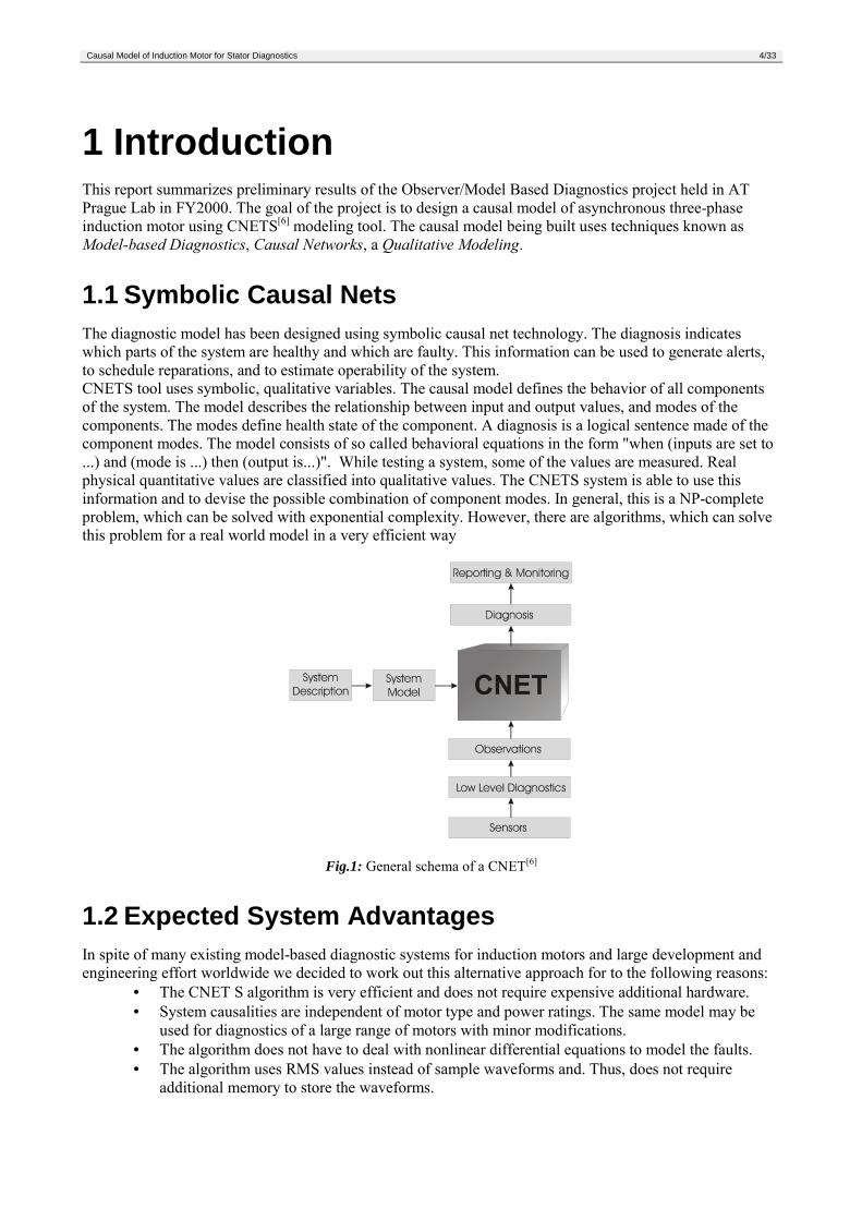
1.1 Symbolic Causal NetsThe diagnostic model has been designed using symbolic causal net technology. The diagnosis indicateswhich parts of the system are healthy and which are faulty. This information can be used to generate alerts,to schedule reparations, and to estimate operability of the system.CNETS tool uses symbolic, qualitative variables. The causal model defines the behavior of all componentsof the system. The model describes the relationship between input and output values, and modes of thecomponents. The modes define health state of the component. A diagnosis is a logical sentence made of thecomponent modes. The model consists of so called behavioral equations in the form "when (inputs are set to...) and (mode is ...) then (output is...)". While testing a system, some of the values are measured. Realphysical quantitative values are classified into qualitative values. The CNETS system is able to use thisinformation and to devise the possible combination of component modes. In general, this is a NP-completeproblem, which can be solved with exponential complexity. However, there are algorithms, which can solvethis problem for a real world model in a very efficient way
Fig.1: General schema of a CNET[6]
1.2 Expected System AdvantagesIn spite of many existing model-based diagnostic systems for induction motors and large development andengineering effort worldwide we decided to work out this alternative approach for to the following reasons:
• The CNET S algorithm is very efficient and does not require expensive additional hardware.• System causalities are independent of motor type and power ratings. The same model may be
used for diagnostics of a large range of motors with minor modifications.• The algorithm does not have to deal with nonlinear differential equations to model the faults.• The algorithm uses RMS values instead of sample waveforms and. Thus, does not require
additional memory to store the waveforms.
Causal Model of Induction Motor for Stator Diagnostics 5/33
2 Causal Model of Induction MotorA machine with only amortisseur windings is called an induction machine. Such machines are calledinduction machines because the rotor voltage (which produces the rotor current and the rotor magnetic field)is induced in the rotor windings rather than being physically connected by wires. Although it is possible touse an induction machine as either a motor or a generator, it has many disadvantages as a generator and so israrely used in that manner. For this reason, induction machines are usually referred to as induction motors.
There are two different types of rotors of induction motors, which can be placed inside the stator. One iscalled a squirrel-cage rotor or simply a cage rotor, while the other is called a wound rotor. A squirrel-cagerotor consists of a series of conducting bars laid into slots carved in the face of the rotor and shorted at eitherend by large shorting rings. The other type of rotor is called a wound rotor. A wound rotor has a complete setof three-phase windings that are mirror images of the windings on the stator.
Induction motor (IM) is a quite complex, non-linear system. The set of differential equations is mostly usedfor his mathematical description.
2.1 Standard Mathematical Model of Induction Motor
In an AC machine under normal operating conditions, there are two magnetic fields present – a magneticfield from rotor circuit and another magnetic field from the stator circuit. The interaction of these twomagnetic fields produces the induced torque within the machine.
One major principle of IM operation is that if a three-phase set of currents, each of equal magnitude anddiffering in phase by 120°, flows in an armature winding, then it will produce a rotating magnetic field ofconstant magnitude. The three phases of the armature windings must be 120 electrical degrees apart.
One of the main assumptions used in the modeling of many types of AC machines is that the machinewindings are arranged so that the resultant magnetic field produced by the windings is spatially sinusoidal. Anormal AC machine usually has three windings spaced at 120° electrical, and each of these windingsproduces a spatially sinusoidal magnetic field when fed with a current.Why is this assumption so important? From a modeling point of view the sinusoidal functions have a rich setof mathematical properties which make the modeling of machines analytically tractable. One of the keyproperties of sinusoidal functions is their connection with vectors, and the consequent ability to takeorthogonal components of them.
Whilst the sinusoidal assumption is very important, other assumptions are also made in order to make themodeling of the machine tractable. These assumptions are:
• Motor id fed by a balanced 3-phase power supply.• The stator windings are assumed to be sinusoidally distributed. When excited with current a
sinusoidal spatial distribution of magnetic field is produced.• The machine does not exhibit any stator or rotor slotting effects.• The machine iron is a linear material, i.e. it is not subject to magnetic saturation effects. The
permeability of the material is very large in comparison to air. Therefore the permeance of themagnetic paths is dominated by the air gaps.
• The airgap flux density waveforms can be adequately represented by the fundamentalcomponent.
• Resistances and inductances are equal for each phase
Causal Model of Induction Motor for Stator Diagnostics 6/33
2.1.1 Differential Equations of Induction Motor
Let us begin with the basic equations for the induction machine. We simply write expressions for both thestator and the rotor. Note that the equation for each of these has been written in its nature reference frame(i.e. stationary for the stator and rotating with the rotor for the rotor):
dtd
iRu SSSS
Ψ+=
dtdiRu R
RRRΨ+=
The expressions for the flux linkage vectors are
Rj
mSSS ieLiL ϑ+=Ψ
Sj
mRRR ieLiL ϑ−+=ΨOne particular version of the torque expression is derived as follows
*Im23
RSR
mpi i
LLpm Ψ⋅=
Li mdtdJm += ω
where uS is stator voltage, iS (iR) is stator (rotor) current, RS (RR) is stator (rotor) resistance, LS (LR) is stator(rotor) inductance, ΨS (ΨR) is stator (rotor) flux linkage, ωs is synchronnous angular speed, ω is rotor angularspeed, ϑ is rotor angular position ( = dtωϑ ), Lm is magnetizing inductance, mi is electromagnetic (driving)torque, mL is load torque and J is moment of inertia.
2.1.2 Equivalent Circuit and Phasor Diagram
An induction motor works by inducing voltages and currents in the rotor of the machine, and for that reasonhas sometimes been called a rotating transformer. Like a transformer, the primary (stator) induces a voltagein the secondary (rotor), but unlike a transformer, the secondary frequency is not necessarily the same as theprimary frequency.Like any transformer, there is a certain resistance and self-inductance in the primary (stator) windings, whichmust be represented in the equivalent circuit of the machine. The stator resistance will be called Rs , and thestator reactance will be called Xs.
To produce the final per-phase equivalent circuit for an induction motor, it is necessary to refer the rotor partof the model over to the stator circuit’s voltage level.
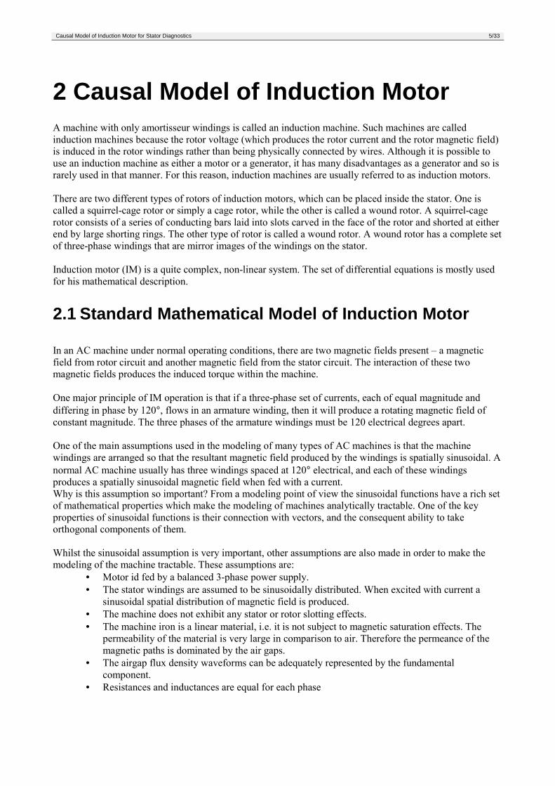
The final per-phase equivalent circuit of the induction motor is shown in Fig.2.
Fig.2: The per-phase equivalent circuit of an induction motor
For the steady-state condition, the voltage differential equations can be expressed in the following form( ) iSSSS UIjXRU ~~~ ++= σ
Causal Model of Induction Motor for Stator Diagnostics 7/33
iRRR UIjX
sR ~~0 +
+= σ
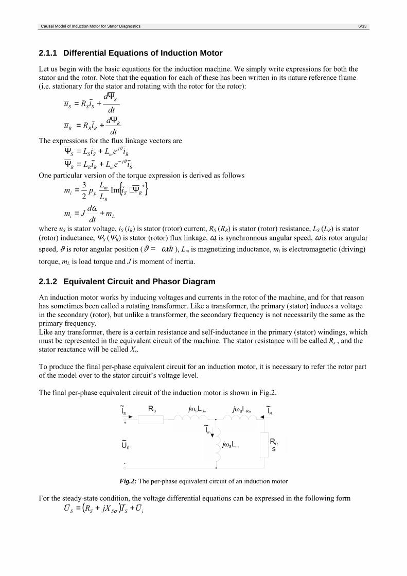
where mmi IjXU ~~ = is so-called induced voltage.A phasor diagram on Fig.3 corresponds to the equations and equivalent scheme shown above.
Fig.3: Phasor diagram of induction motor
The concept of the three-phase induction motor as a transformer enables a phasor diagram of the motorcurrents and voltages to be drawn. With symmetrical phase windings and a balanced power supply, a singlephasor diagram is adequate, the diagrams for the other two phases being identical but displaced 120° inphase.The equivalent circuit matches motor conditions seen in practice. In most cases it will therefore be possibleto describe the operation of an induction motor on the basis of this diagram.
Applicability of standard model of induction motor for diagnostics purposesSome basic simplifying assumptions had to be taken into account to derive standard equivalent scheme forinduction motor. Unfortunately, these assumptions don’t allow us to use this model for a faulty machineanalysis, because assumptions mentioned above are not fulfilled anymore in this case (especially equalvalues of resistances and inductances and symmetry of currents and voltages).
2.2 Failures of Induction MotorsTo fulfill one of the goals of this project: To develop simple diagnostic tool with no extra hardware andsignal-processing requirements, only terminal currents and voltages are used for diagnosis.In the first stage of research, only algorithms for stator failure detection will be developed. Diagnostics ofother faults of induction motor (rotor, shaft, bearings) require more complex monitoring of other signals andquantities.On the other hand, stator fault is the most often failure, so it is essential to have a precious stator-faultdetection algorithm before we will take into consideration other types of faults.
Causal Model of Induction Motor for Stator Diagnostics 8/33
2.2.1 Behavior of an Induction Motor During Stator Failure
In real machines, the stator construction is a bit complicated. Normal AC machine stators consist of severalcoils in each phase distributed in slots around the inner surface of the stator. In larger machines, each coil is aperformed unit consisting of a number of turns. Each turn is insulated from the others and from the side ofthe stator itself. The voltage in any single turn of wire is very small, and it is only by placing many of theseturns in series that reasonable voltages can be produced. This large number of turns is normally physicallydivided among several coils, and the coils are placed in slots equally spaced along the surface of the stator[2].
If three coils are placed around the rotor magnetic field then the voltages induced in each of them will be thesame in magnitude but will differ in phase by 120°. A three-phase set of currents can generate a uniformrotating magnetic field in a machine stator, and a uniform rotating magnetic field can generate a three-phaseset of voltages in such a stator.
When dissymetry exists, as when the phase voltages, currents, or impedances are unbalanced, the motorworking conditions and his behavior are changed. For this cases the symmetrical component method isuseful[1].
In this stage of research we consider the following assumptions:• balanced symmetrical and stable 3-phase power supply• constant load• healthy rotor and mechanical parts of motor
Stator failures are the main cause of outages in induction motors. These faults are caused by four differenttypes of stresses acting on insulation system.Stresses on stator insulation during motor operation are usually grouped in the following way[5]:
Mechanical – These are caused by the fact that both, starting operations or short-circuits, produceimportant electrodynamic stresses. Insufficient end winding bonding or incorrectstator wedging are the main source of degradation.
Electrical – These are normally produced by overvoltages caused by switching maneuvers orsupply perturbations. Degradations produced by other causes such as cracking,separation between conductors and insulation, aging or pollution is the main originof electrical failures.
Thermal – Winding temperature increase can be caused by insufficient ventilation or anincrease in motor losses. The most common causes for losses increasing areoverloading or excessive consecutive starting cycles for which the machine is notdesigned. In all the cases, increasing the insulation temperature over the limitsdefined for its insulation class produces premature material aging and the consequentlosses of its mechanical and dielectrical characteristics.
Environmental factors – Environmental effects are particularly important in machines withlow protection indices. Humidity, acids, dust containing conductorparticles or the presence of foreign bodies can produce a highdegradation level. Insulation aging reduces electrical and mechanicalresistance of the insulation. In this way, an overvoltage waveproduced by an atmospheric discharge, a switching maneuvers or amechanical transient effort can be the cause of insulation breakingand the appearance of a short-circuit.
If some type of deficiency related to the manufacturing process exists or the motor is not correctlydimensioned the failure can appear without any previous aging. In any of the cases, the remaining life of themachine will be dependent on the properties of the insulation system and capacity to perform its function.The four types of stresses affect insulation in different ways, but it can be said that every one interact witheach of the others in such a way that degradation caused by one of them increases degradation caused by therest.
Causal Model of Induction Motor for Stator Diagnostics 9/33
Different types of failures can develop under these stresses. Most specialists consider turn-to-turn short-circuits to be the most common stator failure, especially in random-wound motors. In most cases, this typefault progresses to a coil-to-coil, phase-to-phase or phase-to-ground failures, causing the final breakdown ofthe motor[5].
Let’s consider only one type of stator fault in one instant per phase.The most of assumptions mentioned in this report are to be removed or changed as our diagnostic algorithmwill become more sophisticated and precious.
Turn-to-turn FaultThis type of failure is caused by an insulation breakdown between two turns in the same phase. This failurehas the same effect as a shading coil inserted into the winding has. A very high current (a several timeshigher than normal current) arises in this coil. A magnetic field produced in this shading coil then affect thetotal magnetic flux in the phase.
Let’s assume turn-to-turn failure in the phase a.Voltage equation for the phase a is
dtdiRu a
aaaΨ+= , (1)
The total flux linking the phase a isRaSaa Ψ+Ψ=Ψ , (2)
where ΨSa is flux caused by stator currents and ΨRa is flux caused by rotor currents according tocacbabaSaSa iMiMiL ++=Ψ (3)
CaCBaBAaARa iMiMiM ++=Ψ (4)where LSa is self inductance of phase a, Max is mutual inductance between phase a and x.
In the case of turn-to-turn fault in the phase a, the magnetic flux produced by shading coil will weaken thetotal magnetic flux Ψa in the phase a. Time derivation of Ψa will be lower, voltage drop across the resistanceRa will be higher. (The value of Ra will be lower as a consequence of turn-to-turn fault, but this change affectvoltage drop only negligibly.Consequence of a turn-to-turn fault in stator phase a is increase of current Ia.
The change of current Ia causes a change of magnetic fluxes linking the stator phases.The total fluxes linking the phases b and c are
RbSbb Ψ+Ψ=Ψ
RcScc Ψ+Ψ=Ψ .Let’s assume no changes of rotor current symmetry during any stator failure. ThenΨRa=ΨRb=ΨRc.From the following expressions
cbcaabbSbSb iMiMiL ++=Ψ
bbcaaccScSc iMiMiL ++=Ψ ,we can see that current Ia affects fluxes in phase b and c through the mediation of the mutual inductances.The change of Ia brings the change of magnetic fluxes in the adjacent phases as a next step. It depends on thephase order where the magnetic flux becomes higher and where becomes lower. The nature of thisphenomenon is given by a spatial distribution of stator winding.
Demonstration and explanation of such behaviour of IM can be done using phasor diagrams. These diagramswill not describe situation inside the motor exactly, but they will be very useful for a better understanding ofthe phase currents changes during stator failures.
Causal Model of Induction Motor for Stator Diagnostics 10/33
Just as a three-phase set of currents in a stator can produce a rotating magnetic field, a rotating magnetic fieldcan produce a three-phase set of voltages in the coils of a stator. The equations governing the inducedvoltage in a three-phase stator will be developed in this section.
We will start with equations (1)-(4). We will use phasors instead of instantaneous values.Magnetic flux time derivation is induced voltage Ui. Rotor magnetic flux linked with phase a is constant,therefore also voltage induced in stator due to this flux is constant (UiRa).We can write for flux time derivation:
iRaiSaciSabiSaaiRac
acb
aba
SaRaSaa UUUUU
dtidM
dtidM
dtidL
dtd
dtd
dtd +++=+++=Ψ+Ψ=Ψ
Voltage equation (1) is theniRaiSaciSabiSaaaaa UUUUIRU ++++= (5)
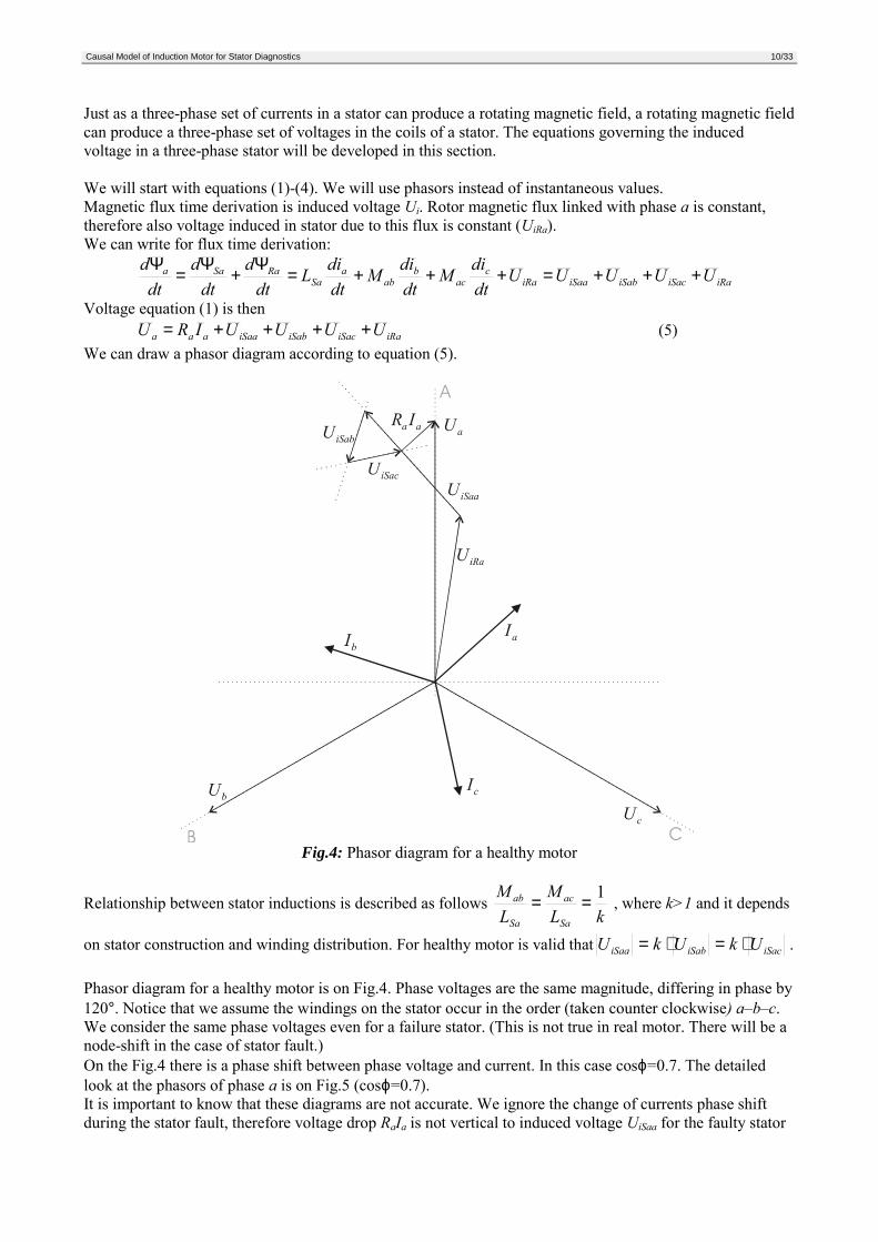
We can draw a phasor diagram according to equation (5).
Fig.4: Phasor diagram for a healthy motor
Relationship between stator inductions is described as follows kL
MLM
Sa
ac
Sa
ab 1== , where k>1 and it depends
on stator construction and winding distribution. For healthy motor is valid that iSaciSabiSaa UkUkU ⋅=⋅= .
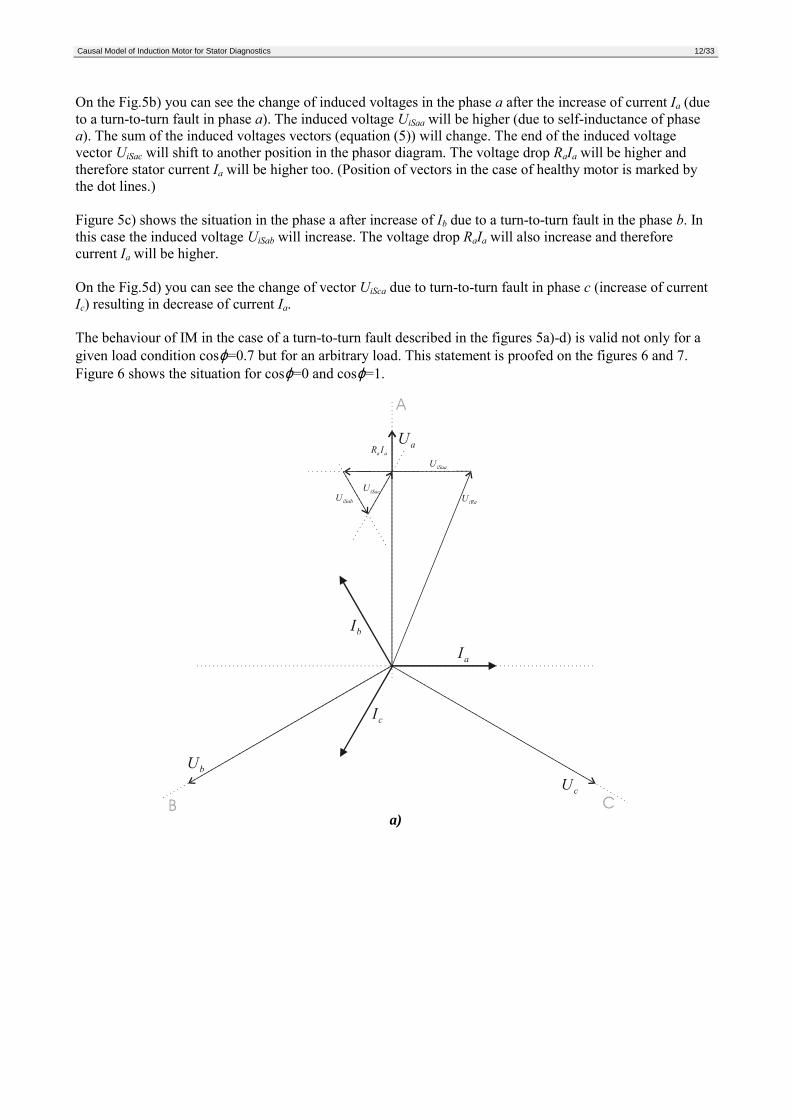
Phasor diagram for a healthy motor is on Fig.4. Phase voltages are the same magnitude, differing in phase by120°. Notice that we assume the windings on the stator occur in the order (taken counter clockwise) a–b–c.We consider the same phase voltages even for a failure stator. (This is not true in real motor. There will be anode-shift in the case of stator fault.)On the Fig.4 there is a phase shift between phase voltage and current. In this case cosϕ=0.7. The detailedlook at the phasors of phase a is on Fig.5 (cosϕ=0.7).It is important to know that these diagrams are not accurate. We ignore the change of currents phase shiftduring the stator fault, therefore voltage drop RaIa is not vertical to induced voltage UiSaa for the faulty stator
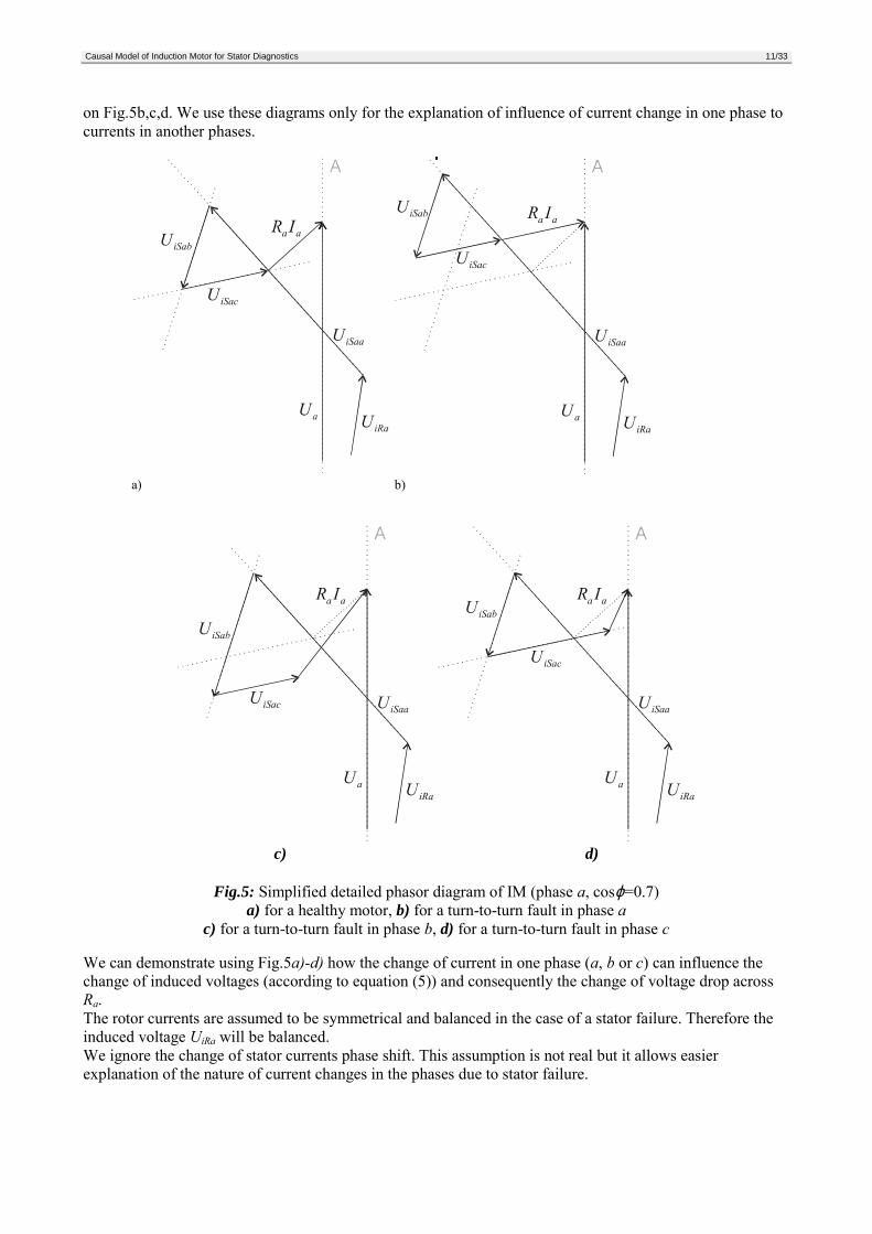
Causal Model of Induction Motor for Stator Diagnostics 11/33
on Fig.5b,c,d. We use these diagrams only for the explanation of influence of current change in one phase tocurrents in another phases.
a) b)
c) d)
Fig.5: Simplified detailed phasor diagram of IM (phase a, cosϕ=0.7)a) for a healthy motor, b) for a turn-to-turn fault in phase a
c) for a turn-to-turn fault in phase b, d) for a turn-to-turn fault in phase c
We can demonstrate using Fig.5a)-d) how the change of current in one phase (a, b or c) can influence thechange of induced voltages (according to equation (5)) and consequently the change of voltage drop acrossRa.The rotor currents are assumed to be symmetrical and balanced in the case of a stator failure. Therefore theinduced voltage UiRa will be balanced.We ignore the change of stator currents phase shift. This assumption is not real but it allows easierexplanation of the nature of current changes in the phases due to stator failure.
Causal Model of Induction Motor for Stator Diagnostics 12/33
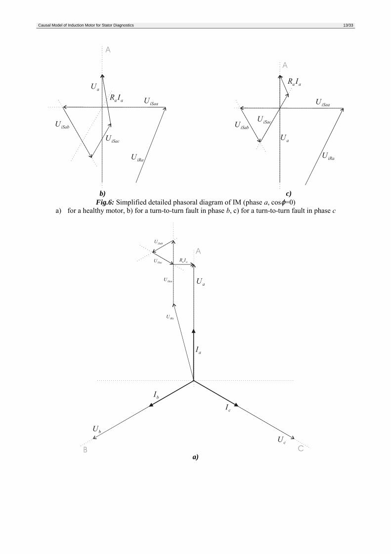
On the Fig.5b) you can see the change of induced voltages in the phase a after the increase of current Ia (dueto a turn-to-turn fault in phase a). The induced voltage UiSaa will be higher (due to self-inductance of phasea). The sum of the induced voltages vectors (equation (5)) will change. The end of the induced voltagevector UiSac will shift to another position in the phasor diagram. The voltage drop RaIa will be higher andtherefore stator current Ia will be higher too. (Position of vectors in the case of healthy motor is marked bythe dot lines.)
Figure 5c) shows the situation in the phase a after increase of Ib due to a turn-to-turn fault in the phase b. Inthis case the induced voltage UiSab will increase. The voltage drop RaIa will also increase and thereforecurrent Ia will be higher.
On the Fig.5d) you can see the change of vector UiSca due to turn-to-turn fault in phase c (increase of currentIc) resulting in decrease of current Ia.
The behaviour of IM in the case of a turn-to-turn fault described in the figures 5a)-d) is valid not only for agiven load condition cosϕ=0.7 but for an arbitrary load. This statement is proofed on the figures 6 and 7.Figure 6 shows the situation for cosϕ=0 and cosϕ=1.
a)
Causal Model of Induction Motor for Stator Diagnostics 13/33
b) c)
Fig.6: Simplified detailed phasoral diagram of IM (phase a, cosϕ=0)a) for a healthy motor, b) for a turn-to-turn fault in phase b, c) for a turn-to-turn fault in phase c
a)
Causal Model of Induction Motor for Stator Diagnostics 14/33
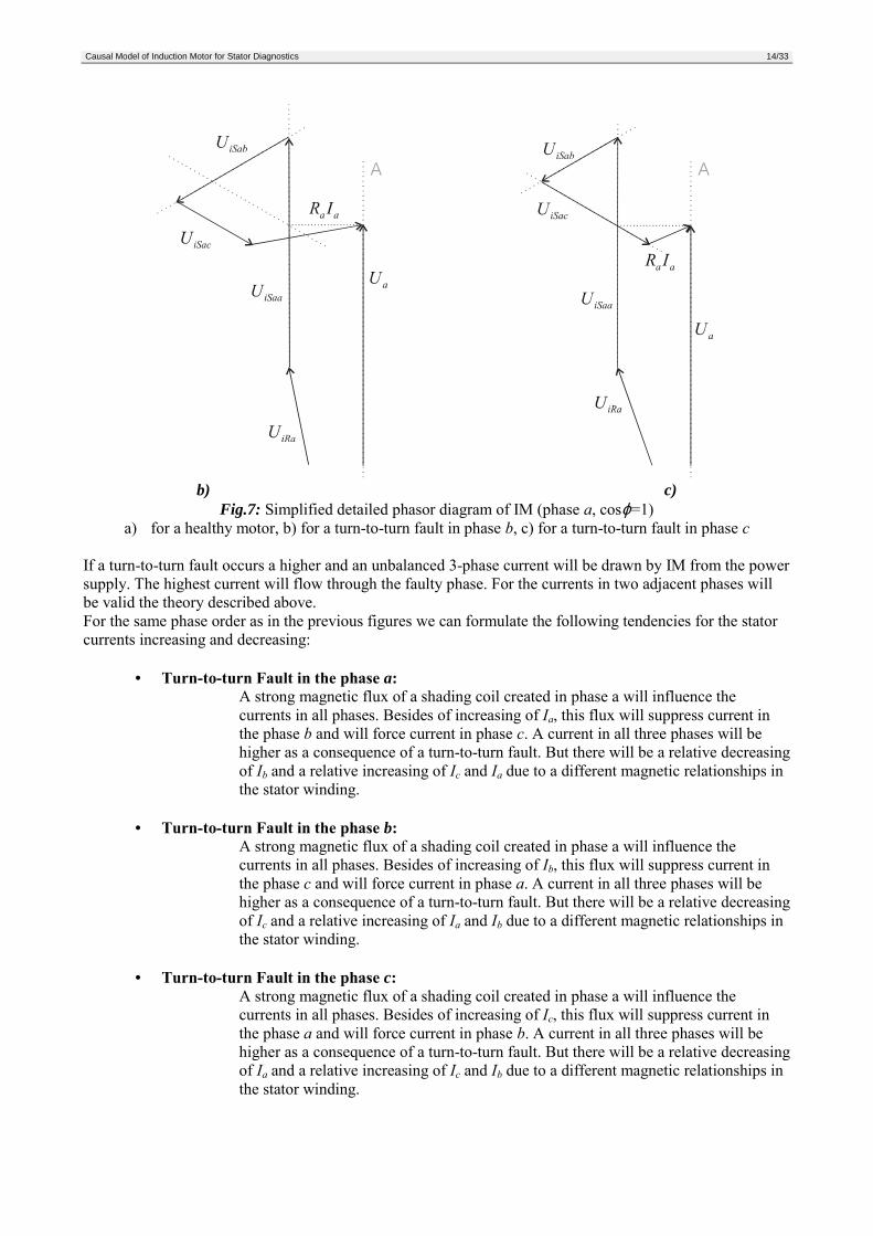
b) c)Fig.7: Simplified detailed phasor diagram of IM (phase a, cosϕ=1)
a) for a healthy motor, b) for a turn-to-turn fault in phase b, c) for a turn-to-turn fault in phase c
If a turn-to-turn fault occurs a higher and an unbalanced 3-phase current will be drawn by IM from the powersupply. The highest current will flow through the faulty phase. For the currents in two adjacent phases willbe valid the theory described above.For the same phase order as in the previous figures we can formulate the following tendencies for the statorcurrents increasing and decreasing:
• Turn-to-turn Fault in the phase a:A strong magnetic flux of a shading coil created in phase a will influence thecurrents in all phases. Besides of increasing of Ia, this flux will suppress current inthe phase b and will force current in phase c. A current in all three phases will behigher as a consequence of a turn-to-turn fault. But there will be a relative decreasingof Ib and a relative increasing of Ic and Ia due to a different magnetic relationships inthe stator winding.
• Turn-to-turn Fault in the phase b:A strong magnetic flux of a shading coil created in phase a will influence thecurrents in all phases. Besides of increasing of Ib, this flux will suppress current inthe phase c and will force current in phase a. A current in all three phases will behigher as a consequence of a turn-to-turn fault. But there will be a relative decreasingof Ic and a relative increasing of Ia and Ib due to a different magnetic relationships inthe stator winding.
• Turn-to-turn Fault in the phase c:A strong magnetic flux of a shading coil created in phase a will influence thecurrents in all phases. Besides of increasing of Ic, this flux will suppress current inthe phase a and will force current in phase b. A current in all three phases will behigher as a consequence of a turn-to-turn fault. But there will be a relative decreasingof Ia and a relative increasing of Ic and Ib due to a different magnetic relationships inthe stator winding.
Causal Model of Induction Motor for Stator Diagnostics 15/33
The sum of instantaneous values of phase currents should be zero in the case of a turn-to-turn fault.The tendencies are brought together in the next table.
Relative change of a phase currentFault Type phase a phase b phase c
Turn-to-turn in phase A increase ↑↑↑↑↑↑↑↑ decrease ↓↓↓↓ increase ↑↑↑↑Turn-to-turn in phase B increase ↑↑↑↑ increase ↑↑↑↑↑↑↑↑ decrease ↓↓↓↓Turn-to-turn in phase C decrease ↓↓↓↓ increase ↑↑↑↑ increase ↑↑↑↑↑↑↑↑
Table 1 Relative changes of stator currents caused by turn-to-turn faults
A big part of the causal model of IM is based on these tendencies.
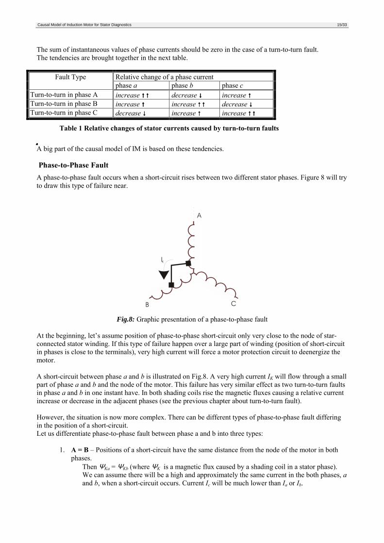
Phase-to-Phase FaultA phase-to-phase fault occurs when a short-circuit rises between two different stator phases. Figure 8 will tryto draw this type of failure near.
Fig.8: Graphic presentation of a phase-to-phase fault
At the beginning, let’s assume position of phase-to-phase short-circuit only very close to the node of star-connected stator winding. If this type of failure happen over a large part of winding (position of short-circuitin phases is close to the terminals), very high current will force a motor protection circuit to deenergize themotor.
A short-circuit between phase a and b is illustrated on Fig.8. A very high current IK will flow through a smallpart of phase a and b and the node of the motor. This failure has very similar effect as two turn-to-turn faultsin phase a and b in one instant have. In both shading coils rise the magnetic fluxes causing a relative currentincrease or decrease in the adjacent phases (see the previous chapter about turn-to-turn fault).
However, the situation is now more complex. There can be different types of phase-to-phase fault differingin the position of a short-circuit.Let us differentiate phase-to-phase fault between phase a and b into three types:
1. A = B – Positions of a short-circuit have the same distance from the node of the motor in bothphases.
Then ΨKa = ΨKb (where ΨK is a magnetic flux caused by a shading coil in a stator phase).We can assume there will be a high and approximately the same current in the both phases, aand b, when a short-circuit occurs. Current Ic will be much lower than Ia or Ib.
Causal Model of Induction Motor for Stator Diagnostics 16/33
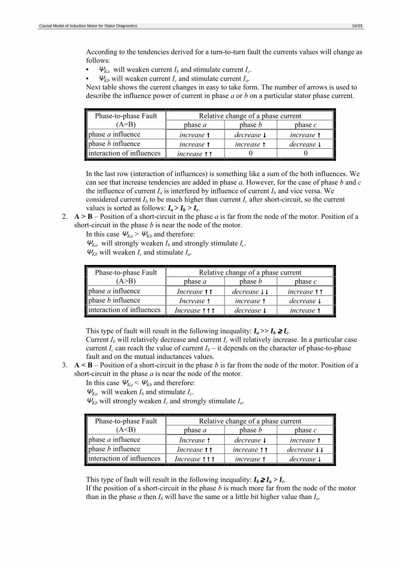
According to the tendencies derived for a turn-to-turn fault the currents values will change asfollows:• ΨKa will weaken current Ib and stimulate current Ic.• ΨKb will weaken current Ic and stimulate current Ia.Next table shows the current changes in easy to take form. The number of arrows is used todescribe the influence power of current in phase a or b on a particular stator phase current.
Relative change of a phase currentPhase-to-phase Fault(A=B) phase a phase b phase c
phase a influence increase ↑↑↑↑ decrease ↓↓↓↓ increase ↑↑↑↑phase b influence increase ↑↑↑↑ increase ↑↑↑↑ decrease ↓↓↓↓interaction of influences increase ↑↑↑↑↑↑↑↑ 0 0
In the last row (interaction of influences) is something like a sum of the both influences. Wecan see that increase tendencies are added in phase a. However, for the case of phase b and cthe influence of current Ia is interfered by influence of current Ib and vice versa. Weconsidered current Ib to be much higher than current Ic after short-circuit, so the currentvalues is sorted as follows: Ia > Ib > Ic.
2. A > B – Position of a short-circuit in the phase a is far from the node of the motor. Position of ashort-circuit in the phase b is near the node of the motor.
In this case ΨKa > ΨKb and therefore:ΨKa will strongly weaken Ib and strongly stimulate Ic.ΨKb will weaken Ic and stimulate Ia.
Relative change of a phase currentPhase-to-phase Fault(A>B) phase a phase b phase c
phase a influence Increase ↑↑↑↑↑↑↑↑ decrease ↓↓↓↓↓↓↓↓ increase ↑↑↑↑↑↑↑↑phase b influence Increase ↑↑↑↑ increase ↑↑↑↑ decrease ↓↓↓↓interaction of influences Increase ↑↑↑↑↑↑↑↑↑↑↑↑ decrease ↓↓↓↓ increase ↑↑↑↑
This type of fault will result in the following inequality: Ia >> Ib ≥≥≥≥ Ic.Current Ib will relatively decrease and current Ic will relatively increase. In a particular casecurrent Ic can reach the value of current Ib – it depends on the character of phase-to-phasefault and on the mutual inductances values.
3. A < B – Position of a short-circuit in the phase b is far from the node of the motor. Position of ashort-circuit in the phase a is near the node of the motor.
In this case ΨKa < ΨKb and therefore:ΨKa will weaken Ib and stimulate Ic.ΨKb will strongly weaken Ic and strongly stimulate Ia.
Relative change of a phase currentPhase-to-phase Fault(A<B) phase a phase b phase c
phase a influence Increase ↑↑↑↑ decrease ↓↓↓↓ increase ↑↑↑↑phase b influence Increase ↑↑↑↑↑↑↑↑ increase ↑↑↑↑↑↑↑↑ decrease ↓↓↓↓↓↓↓↓interaction of influences Increase ↑↑↑↑↑↑↑↑↑↑↑↑ increase ↑↑↑↑ decrease ↓↓↓↓
This type of fault will result in the following inequality: Ib ≥≥≥≥ Ia > Ic.If the position of a short-circuit in the phase b is much more far from the node of the motorthan in the phase a then Ib will have the same or a little bit higher value than Ia.
Causal Model of Induction Motor for Stator Diagnostics 17/33
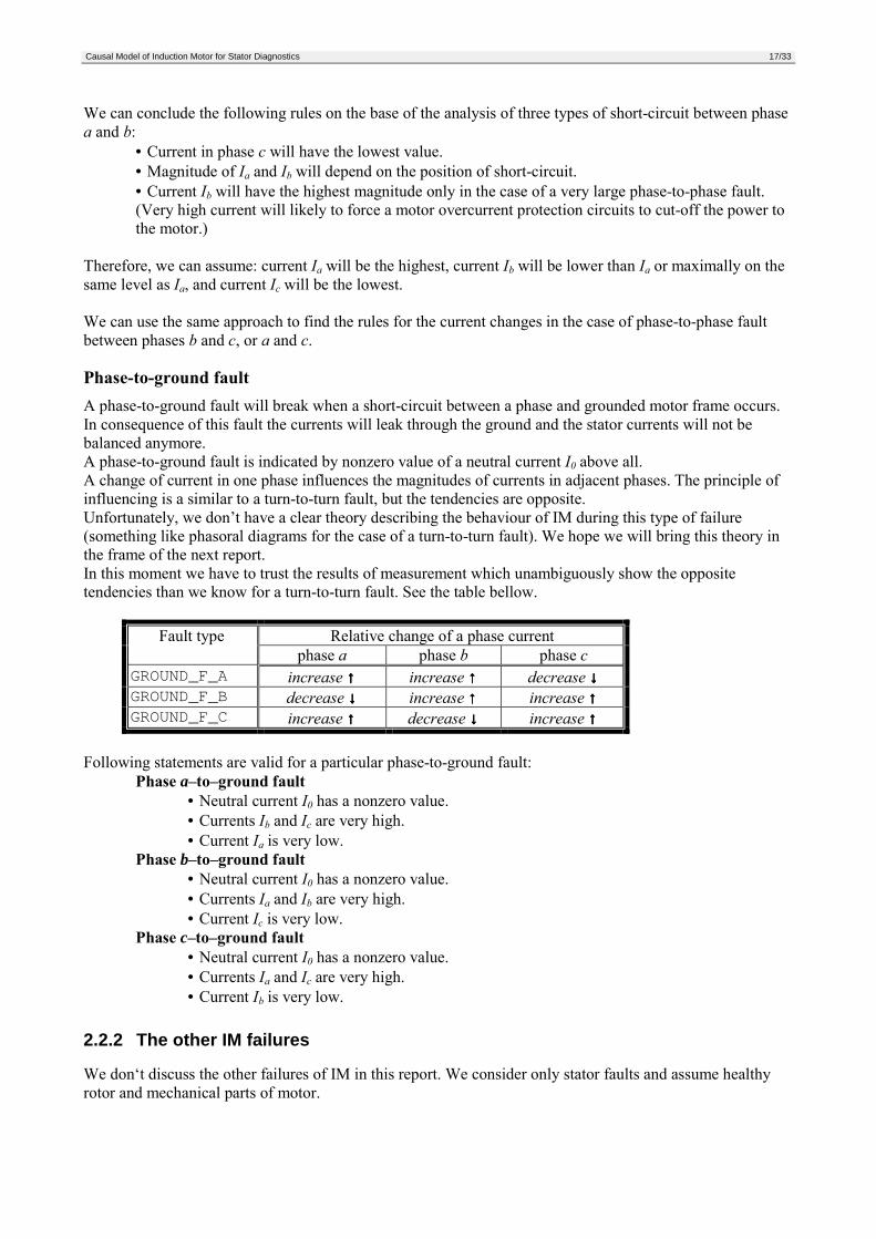
We can conclude the following rules on the base of the analysis of three types of short-circuit between phasea and b:
• Current in phase c will have the lowest value.• Magnitude of Ia and Ib will depend on the position of short-circuit.• Current Ib will have the highest magnitude only in the case of a very large phase-to-phase fault.(Very high current will likely to force a motor overcurrent protection circuits to cut-off the power tothe motor.)
Therefore, we can assume: current Ia will be the highest, current Ib will be lower than Ia or maximally on thesame level as Ia, and current Ic will be the lowest.
We can use the same approach to find the rules for the current changes in the case of phase-to-phase faultbetween phases b and c, or a and c.
Phase-to-ground faultA phase-to-ground fault will break when a short-circuit between a phase and grounded motor frame occurs.In consequence of this fault the currents will leak through the ground and the stator currents will not bebalanced anymore.A phase-to-ground fault is indicated by nonzero value of a neutral current I0 above all.A change of current in one phase influences the magnitudes of currents in adjacent phases. The principle ofinfluencing is a similar to a turn-to-turn fault, but the tendencies are opposite.Unfortunately, we don’t have a clear theory describing the behaviour of IM during this type of failure(something like phasoral diagrams for the case of a turn-to-turn fault). We hope we will bring this theory inthe frame of the next report.In this moment we have to trust the results of measurement which unambiguously show the oppositetendencies than we know for a turn-to-turn fault. See the table bellow.
Relative change of a phase currentFault type phase a phase b phase cGROUND_F_A increase ↑↑↑↑ increase ↑↑↑↑ decrease ↓↓↓↓GROUND_F_B decrease ↓↓↓↓ increase ↑↑↑↑ increase ↑↑↑↑GROUND_F_C increase ↑↑↑↑ decrease ↓↓↓↓ increase ↑↑↑↑
Following statements are valid for a particular phase-to-ground fault:Phase a–to–ground fault
• Neutral current I0 has a nonzero value.• Currents Ib and Ic are very high.• Current Ia is very low.
Phase b–to–ground fault• Neutral current I0 has a nonzero value.• Currents Ia and Ib are very high.• Current Ic is very low.
Phase c–to–ground fault• Neutral current I0 has a nonzero value.• Currents Ia and Ic are very high.• Current Ib is very low.
2.2.2 The other IM failures
We don‘t discuss the other failures of IM in this report. We consider only stator faults and assume healthyrotor and mechanical parts of motor.

Causal Model of Induction Motor for Stator Diagnostics 18/33
2.3 Qualitative VariablesIn contrary to mathematical models, causal models do not use numeric, quantitative values. Causal modelsuse symbolic, qualitative values. The quantitative values are mapped to qualitative values in a preprocessingmodule.
2.3.1 Measured Variables (Observables)
The diagnostic system measures values of stator currents. Lets denote ia(t), ib(t), ic(t) values of currents in the3 phases (t denotes time). The respective effective values of stator currents are Ia, Ib, Ic . The effective valueof current in the center of ‘Y’ winding is denoted 0I . In case of delta winding or if the center of ‘Y’ is notaccessible, the value of 0I may be evaluated in the following way:
( )++= dttititiT
I cba2
0 )()()(1[A]
Next, average of the three effective values will be evaluated:
( )cbaavg IIII ++=31
[A]
Relative values of all currents are defined in the following way:
avg
a
IIASCURRENT =__ [-]
avg
b
IIBSCURRENT =__ [-]
avg
c
IICSCURRENT =__ [-]
avgIISUMSCURRENT 0__ = [-]
We map the relative values to the qualitative values. The variables CURRENT_S_A, CURRENT_S_B, andCURRENT_S_C have three qualitative values: LOW, NORMAL, and HIGH. They use the followingmapping.
Relative (quantitative) value Qualitative value
<0 ; 0.9) LOW<0.9 ; 1.1> NORMAL(1.1 ; ∞) HIGH
The variable CURRENT_S_SUM has two qualitative values ZERO and NONZERO defined by thefollowing mapping.
Relative (quantitative) value Qualitative value
<0 ; 0.1> ZERO(0.1 ; ∞) NONZERO
The last observable used in the model is PHASE_ORDER. It defines the direction in which rotates statormagnetic field. This variable has two qualitative values: ABC and ACB.
Causal Model of Induction Motor for Stator Diagnostics 19/33
2.3.2 System Modes (Assumables)
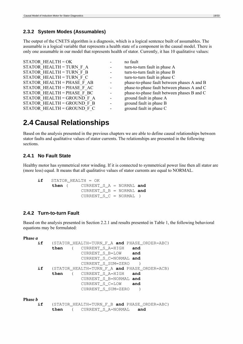
The output of the CNETS algorithm is a diagnosis, which is a logical sentence built of assumables. Theassumable is a logical variable that represents a health state of a component in the causal model. There isonly one assumable in our model that represents health of stator. Currently, it has 10 qualitative values:
STATOR_HEALTH = OK - no faultSTATOR_HEALTH = TURN_F_A - turn-to-turn fault in phase ASTATOR_HEALTH = TURN_F_B - turn-to-turn fault in phase BSTATOR_HEALTH = TURN_F_C - turn-to-turn fault in phase CSTATOR_HEALTH = PHASE_F_AB - phase-to-phase fault between phases A and BSTATOR_HEALTH = PHASE_F_AC - phase-to-phase fault between phases A and CSTATOR_HEALTH = PHASE_F_BC - phase-to-phase fault between phases B and CSTATOR_HEALTH = GROUND_F_A - ground fault in phase ASTATOR_HEALTH = GROUND_F_B - ground fault in phase BSTATOR_HEALTH = GROUND_F_C - ground fault in phase C
2.4 Causal RelationshipsBased on the analysis presented in the previous chapters we are able to define causal relationships betweenstator faults and qualitative values of stator currents. The relationships are presented in the followingsections.
2.4.1 No Fault State
Healthy motor has symmetrical rotor winding. If it is connected to symmetrical power line then all stator are(more less) equal. It means that all qualitative values of stator currents are equal to NORMAL.
if STATOR_HEALTH = OKthen ( CURRENT_S_A = NORMAL and
CURRENT_S_B = NORMAL andCURRENT_S_C = NORMAL )
2.4.2 Turn-to-turn Fault
Based on the analysis presented in Section 2.2.1 and results presented in Table 1, the following behavioralequations may be formulated:
Phase aif (STATOR_HEALTH=TURN_F_A and PHASE_ORDER=ABC)
then ( CURRENT_S_A=HIGH andCURRENT_S_B=LOW andCURRENT_S_C=NORMAL andCURRENT_S_SUM=ZERO )
if (STATOR_HEALTH=TURN_F_A and PHASE_ORDER=ACB)then ( CURRENT_S_A=HIGH and
CURRENT_S_B=NORMAL andCURRENT_S_C=LOW andCURRENT_S_SUM=ZERO )
Phase bif (STATOR_HEALTH=TURN_F_B and PHASE_ORDER=ABC)
then ( CURRENT_S_A=NORMAL and
Causal Model of Induction Motor for Stator Diagnostics 20/33
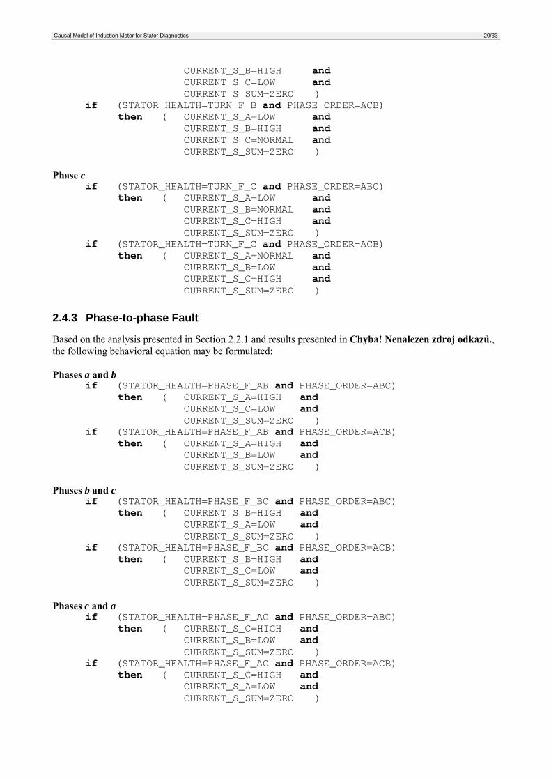
CURRENT_S_B=HIGH andCURRENT_S_C=LOW andCURRENT_S_SUM=ZERO )
if (STATOR_HEALTH=TURN_F_B and PHASE_ORDER=ACB)then ( CURRENT_S_A=LOW and
CURRENT_S_B=HIGH andCURRENT_S_C=NORMAL andCURRENT_S_SUM=ZERO )
Phase cif (STATOR_HEALTH=TURN_F_C and PHASE_ORDER=ABC)
then ( CURRENT_S_A=LOW andCURRENT_S_B=NORMAL andCURRENT_S_C=HIGH andCURRENT_S_SUM=ZERO )
if (STATOR_HEALTH=TURN_F_C and PHASE_ORDER=ACB)then ( CURRENT_S_A=NORMAL and
CURRENT_S_B=LOW andCURRENT_S_C=HIGH andCURRENT_S_SUM=ZERO )
2.4.3 Phase-to-phase Fault
Based on the analysis presented in Section 2.2.1 and results presented in Chyba! Nenalezen zdroj odkazů.,the following behavioral equation may be formulated:
Phases a and bif (STATOR_HEALTH=PHASE_F_AB and PHASE_ORDER=ABC)
then ( CURRENT_S_A=HIGH andCURRENT_S_C=LOW andCURRENT_S_SUM=ZERO )
if (STATOR_HEALTH=PHASE_F_AB and PHASE_ORDER=ACB)then ( CURRENT_S_A=HIGH and
CURRENT_S_B=LOW andCURRENT_S_SUM=ZERO )
Phases b and cif (STATOR_HEALTH=PHASE_F_BC and PHASE_ORDER=ABC)
then ( CURRENT_S_B=HIGH andCURRENT_S_A=LOW andCURRENT_S_SUM=ZERO )
if (STATOR_HEALTH=PHASE_F_BC and PHASE_ORDER=ACB)then ( CURRENT_S_B=HIGH and
CURRENT_S_C=LOW andCURRENT_S_SUM=ZERO )
Phases c and aif (STATOR_HEALTH=PHASE_F_AC and PHASE_ORDER=ABC)
then ( CURRENT_S_C=HIGH andCURRENT_S_B=LOW andCURRENT_S_SUM=ZERO )
if (STATOR_HEALTH=PHASE_F_AC and PHASE_ORDER=ACB)then ( CURRENT_S_C=HIGH and
CURRENT_S_A=LOW andCURRENT_S_SUM=ZERO )
Causal Model of Induction Motor for Stator Diagnostics 21/33
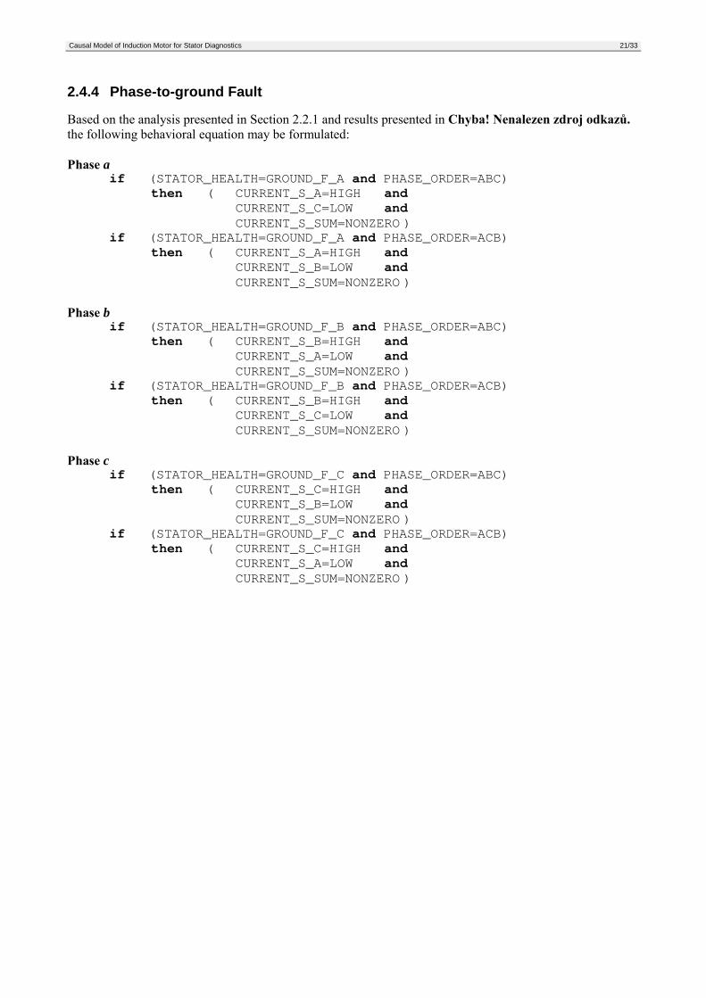
2.4.4 Phase-to-ground Fault
Based on the analysis presented in Section 2.2.1 and results presented in Chyba! Nenalezen zdroj odkazů.the following behavioral equation may be formulated:
Phase aif (STATOR_HEALTH=GROUND_F_A and PHASE_ORDER=ABC)
then ( CURRENT_S_A=HIGH andCURRENT_S_C=LOW andCURRENT_S_SUM=NONZERO )
if (STATOR_HEALTH=GROUND_F_A and PHASE_ORDER=ACB)then ( CURRENT_S_A=HIGH and
CURRENT_S_B=LOW andCURRENT_S_SUM=NONZERO )
Phase bif (STATOR_HEALTH=GROUND_F_B and PHASE_ORDER=ABC)
then ( CURRENT_S_B=HIGH andCURRENT_S_A=LOW andCURRENT_S_SUM=NONZERO )
if (STATOR_HEALTH=GROUND_F_B and PHASE_ORDER=ACB)then ( CURRENT_S_B=HIGH and
CURRENT_S_C=LOW andCURRENT_S_SUM=NONZERO )
Phase cif (STATOR_HEALTH=GROUND_F_C and PHASE_ORDER=ABC)
then ( CURRENT_S_C=HIGH andCURRENT_S_B=LOW andCURRENT_S_SUM=NONZERO )
if (STATOR_HEALTH=GROUND_F_C and PHASE_ORDER=ACB)then ( CURRENT_S_C=HIGH and
CURRENT_S_A=LOW andCURRENT_S_SUM=NONZERO )
Causal Model of Induction Motor for Stator Diagnostics 22/33
3 Laboratory TestsWe verified the theoretical analysis presented in the Section 2 in CTU laboratory. We had an access to aspecially wound induction motor that allows for simulation of many kinds of stator faults.
3.1 Research workplace descriptionA research laboratory for studying an induction motor behavior under abnormal conditions was built in theframe of cooperation between Czech Technical University and Rockwell Advanced Technology Lab inPrague, Czech Republic.The research workplace contains of a PC with a high quality measuring build-in card, an eight-channelamplifier, a current cross detection board, a specially wound induction motor, a dynamometer and otherdevices for power supplying and measuring.A special rewound motor is used for different stator failure emulation.
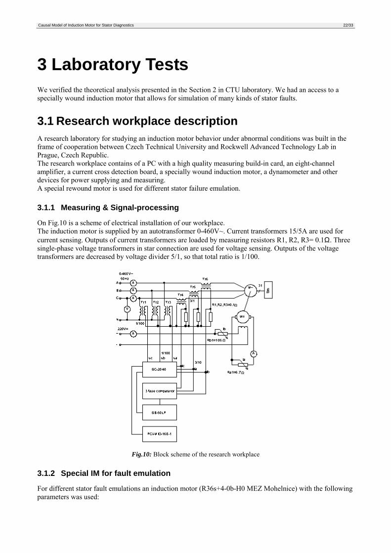
3.1.1 Measuring & Signal-processing
On Fig.10 is a scheme of electrical installation of our workplace.The induction motor is supplied by an autotransformer 0-460V~. Current transformers 15/5A are used forcurrent sensing. Outputs of current transformers are loaded by measuring resistors R1, R2, R3= 0.1Ω. Threesingle-phase voltage transformers in star connection are used for voltage sensing. Outputs of the voltagetransformers are decreased by voltage divider 5/1, so that total ratio is 1/100.
Fig.10: Block scheme of the research workplace
3.1.2 Special IM for fault emulation
For different stator fault emulations an induction motor (R36s+4-0b-H0 MEZ Mohelnice) with the followingparameters was used:
Causal Model of Induction Motor for Stator Diagnostics 23/33
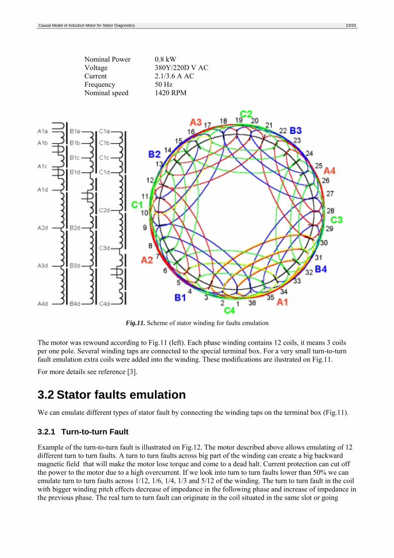
Nominal Power 0.8 kWVoltage 380Y/220D V ACCurrent 2.1/3.6 A ACFrequency 50 HzNominal speed 1420 RPM
Fig.11. Scheme of stator winding for faults emulation
The motor was rewound according to Fig.11 (left). Each phase winding contains 12 coils, it means 3 coilsper one pole. Several winding taps are connected to the special terminal box. For a very small turn-to-turnfault emulation extra coils were added into the winding. These modifications are ilustrated on Fig.11.
For more details see reference [3].
3.2 Stator faults emulationWe can emulate different types of stator fault by connecting the winding taps on the terminal box (Fig.11).
3.2.1 Turn-to-turn Fault
Example of the turn-to-turn fault is illustrated on Fig.12. The motor described above allows emulating of 12different turn to turn faults. A turn to turn faults across big part of the winding can create a big backwardmagnetic field that will make the motor lose torque and come to a dead halt. Current protection can cut offthe power to the motor due to a high overcurrent. If we look into turn to turn faults lower than 50% we canemulate turn to turn faults across 1/12, 1/6, 1/4, 1/3 and 5/12 of the winding. The turn to turn fault in the coilwith bigger winding pitch effects decrease of impedance in the following phase and increase of impedance inthe previous phase. The real turn to turn fault can originate in the coil situated in the same slot or going
Causal Model of Induction Motor for Stator Diagnostics 24/33
together to next slots. The used winding will allow real turn to turn fault only to across up to 1/4 winding oracross the whole winding.
Fig.12: Turn-to-turn Fault
3.2.2 Phase-to-phase Fault
The example of a phase to phase fault is on Fig.13. If we look into phase to phase faults lower than 50% wecan emulate 9 types of faults: 1/12-1/12, 1/12-1/6, 1/12-1/4, 1/6-1/12, 1/6-1/6, 1/6-1/4, 1/4-1/12, 1/4-1/6, 1/4-1/4. A phase to phase fault is very similar to a turn to turn faults in two phases together. Phase to phase faultsare more dangerous, because they can break in larger part of the winding.
Fig.13: Phase-to-phase Fault
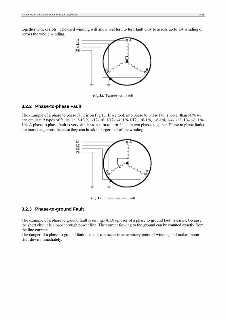
3.2.3 Phase-to-ground Fault
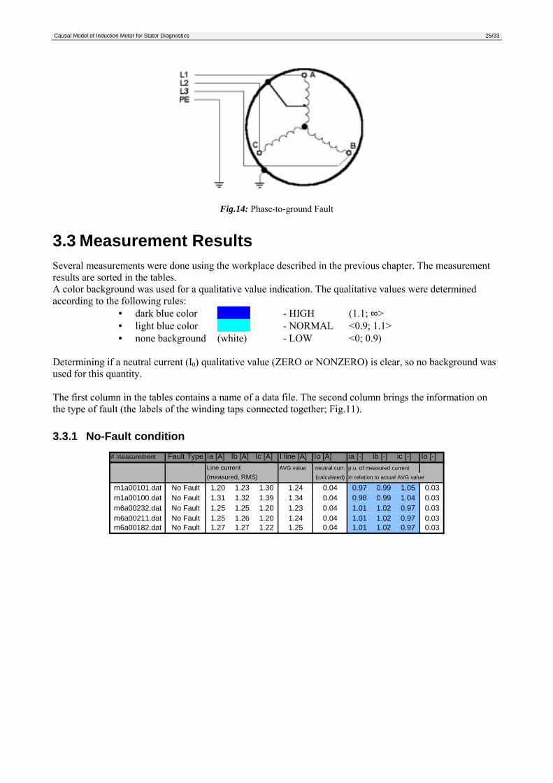
The example of a phase to ground fault is on Fig.14. Diagnoses of a phase to ground fault is easier, becausethe short circuit is closed through power line. The current flowing to the ground can be counted exactly fromthe line currents.The danger of a phase to ground fault is that it can occur in an arbitrary point of winding and makes motorshut-down immediately.
Causal Model of Induction Motor for Stator Diagnostics 25/33
Fig.14: Phase-to-ground Fault
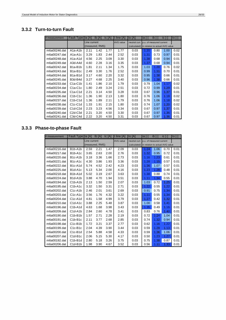
3.3 Measurement ResultsSeveral measurements were done using the workplace described in the previous chapter. The measurementresults are sorted in the tables.A color background was used for a qualitative value indication. The qualitative values were determinedaccording to the following rules:
• dark blue color - HIGH (1.1; ∞>• light blue color - NORMAL <0.9; 1.1>• none background (white) - LOW <0; 0.9)
Determining if a neutral current (I0) qualitative value (ZERO or NONZERO) is clear, so no background wasused for this quantity.
The first column in the tables contains a name of a data file. The second column brings the information onthe type of fault (the labels of the winding taps connected together; Fig.11).
3.3.1 No-Fault condition# measurement Fault Type Ia [A] Ib [A] Ic [A] I line [A] Io [A] ia [-] ib [-] ic [-] Io [-]
Line current AVG value neutral curr. p.u. of measured current(measured, RMS) (calculated) in relation to actual AVG value
m1a00101.dat No Fault 1.20 1.23 1.30 1.24 0.04 0.97 0.99 1.05 0.03m1a00100.dat No Fault 1.31 1.32 1.39 1.34 0.04 0.98 0.99 1.04 0.03m6a00232.dat No Fault 1.25 1.25 1.20 1.23 0.04 1.01 1.02 0.97 0.03m6a00211.dat No Fault 1.25 1.26 1.20 1.24 0.04 1.01 1.02 0.97 0.03m6a00182.dat No Fault 1.27 1.27 1.22 1.25 0.04 1.01 1.02 0.97 0.03
Causal Model of Induction Motor for Stator Diagnostics 26/33
3.3.2 Turn-to-turn Fault# measurement Fault Type Ia [A] Ib [A] Ic [A] I line [A] Io [A] ia [-] ib [-] ic [-] Io [-]
Line current AVG value neutral curr. p.u. of measured current(measured, RMS) (calculated) in relation to actual AVG value
m6a00246.dat A1a-A1b 2.11 1.42 1.77 1.77 0.03 1.20 0.80 1.00 0.02m6a00247.dat A1a-A1c 3.29 1.83 2.44 2.52 0.03 1.31 0.73 0.97 0.01m6a00248.dat A1a-A1d 4.56 2.25 3.09 3.30 0.03 1.38 0.68 0.94 0.01m6a00249.dat A3d-A4d 4.60 2.28 3.16 3.35 0.03 1.37 0.68 0.94 0.01m6a00242.dat B1a-B1b 1.81 2.11 1.34 1.75 0.03 1.03 1.20 0.76 0.02m6a00243.dat B1a-B1c 2.49 3.30 1.76 2.52 0.03 0.99 1.31 0.70 0.01m6a00244.dat B1a-B1d 3.17 4.60 2.20 3.32 0.03 0.95 1.38 0.66 0.01m6a00245.dat B3d-B4d 3.27 4.68 2.25 3.40 0.03 0.96 1.38 0.66 0.01m6a00233.dat C1a-C1b 1.41 1.86 2.10 1.79 0.03 0.79 1.04 1.17 0.02m6a00234.dat C1a-C1c 1.80 2.49 3.24 2.51 0.03 0.72 0.99 1.29 0.01m6a00235.dat C1a-C1d 2.21 3.14 4.50 3.28 0.03 0.67 0.96 1.37 0.01m6a00236.dat C1b-C1c 1.36 1.90 2.13 1.80 0.03 0.76 1.06 1.18 0.02m6a00237.dat C1b-C1d 1.36 1.89 2.11 1.79 0.03 0.76 1.06 1.18 0.02m6a00238.dat C1c-C1d 1.33 1.91 2.15 1.80 0.03 0.74 1.07 1.20 0.02m6a00239.dat C1d-C2d 2.23 3.23 4.56 3.34 0.03 0.67 0.97 1.37 0.01m6a00240.dat C2d-C3d 2.21 3.20 4.50 3.30 0.03 0.67 0.97 1.36 0.01m6a00241.dat C3d-C4d 2.22 3.20 4.50 3.31 0.03 0.67 0.97 1.36 0.01
3.3.3 Phase-to-phase Fault# measurement Fault Type Ia [A] Ib [A] Ic [A] I line [A] Io [A] ia [-] ib [-] ic [-] Io [-]
Line current AVG value neutral curr. p.u. of measured current(measured, RMS) (calculated) in relation to actual AVG value
m6a00216.dat B1b-A1b 2.59 2.21 1.47 2.09 0.03 1.24 1.06 0.70 0.01m6a00217.dat B1b-A1c 3.65 2.63 2.00 2.76 0.03 1.32 0.95 0.72 0.01m6a00220.dat B1c-A1b 3.18 3.36 1.66 2.73 0.03 1.16 1.23 0.61 0.01m6a00221.dat B1c-A1c 4.30 3.86 1.93 3.36 0.03 1.28 1.15 0.57 0.01m6a00222.dat B1c-A1d 5.74 4.52 2.42 4.23 0.03 1.36 1.07 0.57 0.01m6a00225.dat B1d-A1c 5.13 5.34 2.00 4.16 0.03 1.23 1.28 0.48 0.01m6a00218.dat B1b-A1d 5.02 3.19 2.67 3.63 0.03 1.38 0.88 0.74 0.01m6a00224.dat B1d-A1b 3.88 4.70 1.94 3.51 0.03 1.11 1.34 0.55 0.01m6a00194.dat C1b-A1b 2.13 1.50 2.59 2.07 0.03 1.03 0.72 1.25 0.01m6a00195.dat C1b-A1c 3.32 1.50 3.31 2.71 0.03 1.22 0.55 1.22 0.01m6a00202.dat C1c-A1b 2.46 2.01 3.61 2.69 0.03 0.91 0.75 1.34 0.01m6a00203.dat C1c-A1c 3.56 1.76 4.32 3.22 0.03 1.11 0.55 1.34 0.01m6a00204.dat C1c-A1d 4.81 1.58 4.99 3.79 0.03 1.27 0.42 1.32 0.01m6a00210.dat C1d-A1c 3.88 2.25 5.48 3.87 0.03 1.00 0.58 1.41 0.01m6a00196.dat C1b-A1d 4.63 1.68 3.98 3.43 0.03 1.35 0.49 1.16 0.01m6a00209.dat C1d-A1b 2.84 2.60 4.78 3.41 0.03 0.83 0.76 1.40 0.01m6a00190.dat C1b-B1b 1.57 2.71 2.28 2.19 0.03 0.72 1.24 1.04 0.01m6a00191.dat C1b-B1c 2.11 3.77 2.68 2.85 0.03 0.74 1.32 0.94 0.01m6a00198.dat C1c-B1b 1.72 3.21 3.37 2.77 0.03 0.62 1.16 1.22 0.01m6a00199.dat C1c-B1c 2.04 4.39 3.90 3.44 0.03 0.59 1.28 1.13 0.01m6a00200.dat C1c-B1d 2.54 5.88 4.58 4.33 0.03 0.59 1.36 1.06 0.01m6a00207.dat C1d-B1c 2.06 5.15 5.30 4.17 0.03 0.50 1.23 1.27 0.01m6a00192.dat C1b-B1d 2.80 5.18 3.26 3.75 0.03 0.75 1.38 0.87 0.01m6a00206.dat C1d-B1b 1.98 3.90 4.67 3.52 0.03 0.56 1.11 1.33 0.01
Causal Model of Induction Motor for Stator Diagnostics 27/33
3.3.4 Phase-to-Ground Fault# measurement Fault Type Ia [A] Ib [A] Ic [A] I line [A] Io [A] ia [-] ib [-] ic [-] Io [-]
Line current AVG value neutral curr. p.u. of measured current(measured, RMS) (calculated) in relation to actual AVG value
m1a00131.dat A1b-G 1.47 1.45 0.99 1.30 1.20 1.13 1.11 0.76 0.92m1a00132.dat A1c-G 1.95 1.69 0.72 1.45 2.32 1.34 1.16 0.50 1.60m1a00133.dat A1d-G 2.66 1.87 0.48 1.67 3.56 1.59 1.12 0.29 2.13m1a00134.dat B1b-G 0.93 1.45 1.45 1.28 1.08 0.73 1.14 1.14 0.85m1a00135.dat B1c-G 0.65 1.90 1.67 1.41 2.18 0.46 1.35 1.19 1.55m1a00136.dat B1d-G 0.41 2.60 1.87 1.63 3.47 0.25 1.60 1.15 2.13m1a00137.dat C1b-G 1.40 0.95 1.51 1.29 1.13 1.09 0.74 1.17 0.88m1a00138.dat C1c-G 1.62 0.66 1.98 1.42 2.26 1.14 0.46 1.39 1.59m1a00139.dat C1d-G 1.80 0.42 2.67 1.63 3.51 1.10 0.26 1.64 2.15
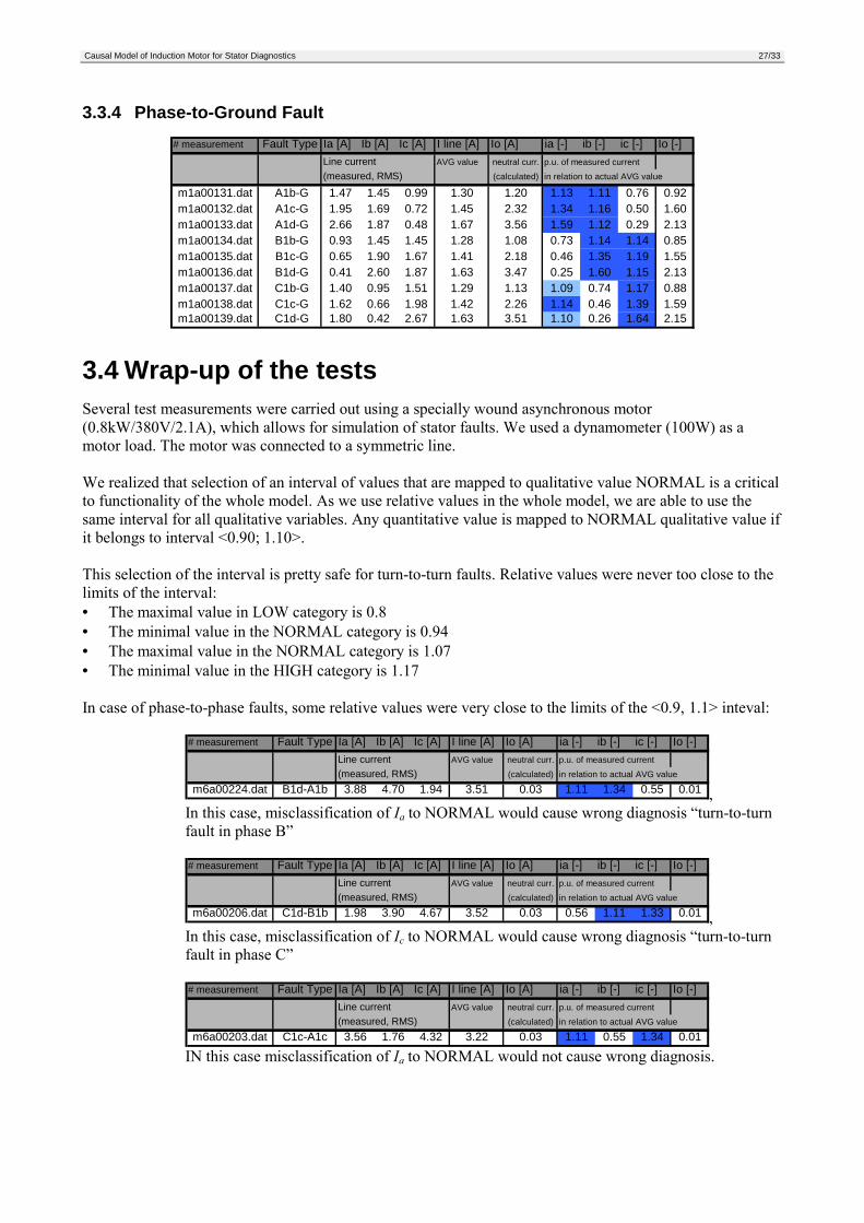
3.4 Wrap-up of the testsSeveral test measurements were carried out using a specially wound asynchronous motor(0.8kW/380V/2.1A), which allows for simulation of stator faults. We used a dynamometer (100W) as amotor load. The motor was connected to a symmetric line.
We realized that selection of an interval of values that are mapped to qualitative value NORMAL is a criticalto functionality of the whole model. As we use relative values in the whole model, we are able to use thesame interval for all qualitative variables. Any quantitative value is mapped to NORMAL qualitative value ifit belongs to interval <0.90; 1.10>.
This selection of the interval is pretty safe for turn-to-turn faults. Relative values were never too close to thelimits of the interval:• The maximal value in LOW category is 0.8• The minimal value in the NORMAL category is 0.94• The maximal value in the NORMAL category is 1.07• The minimal value in the HIGH category is 1.17
In case of phase-to-phase faults, some relative values were very close to the limits of the <0.9, 1.1> inteval:
# measurement Fault Type Ia [A] Ib [A] Ic [A] I line [A] Io [A] ia [-] ib [-] ic [-] Io [-]Line current AVG value neutral curr. p.u. of measured current(measured, RMS) (calculated) in relation to actual AVG value
m6a00224.dat B1d-A1b 3.88 4.70 1.94 3.51 0.03 1.11 1.34 0.55 0.01 ,In this case, misclassification of Ia to NORMAL would cause wrong diagnosis “turn-to-turnfault in phase B”
# measurement Fault Type Ia [A] Ib [A] Ic [A] I line [A] Io [A] ia [-] ib [-] ic [-] Io [-]Line current AVG value neutral curr. p.u. of measured current(measured, RMS) (calculated) in relation to actual AVG value
m6a00206.dat C1d-B1b 1.98 3.90 4.67 3.52 0.03 0.56 1.11 1.33 0.01 ,In this case, misclassification of Ic to NORMAL would cause wrong diagnosis “turn-to-turnfault in phase C”
# measurement Fault Type Ia [A] Ib [A] Ic [A] I line [A] Io [A] ia [-] ib [-] ic [-] Io [-]Line current AVG value neutral curr. p.u. of measured current(measured, RMS) (calculated) in relation to actual AVG value
m6a00203.dat C1c-A1c 3.56 1.76 4.32 3.22 0.03 1.11 0.55 1.34 0.01
IN this case misclassification of Ia to NORMAL would not cause wrong diagnosis.
Causal Model of Induction Motor for Stator Diagnostics 28/33
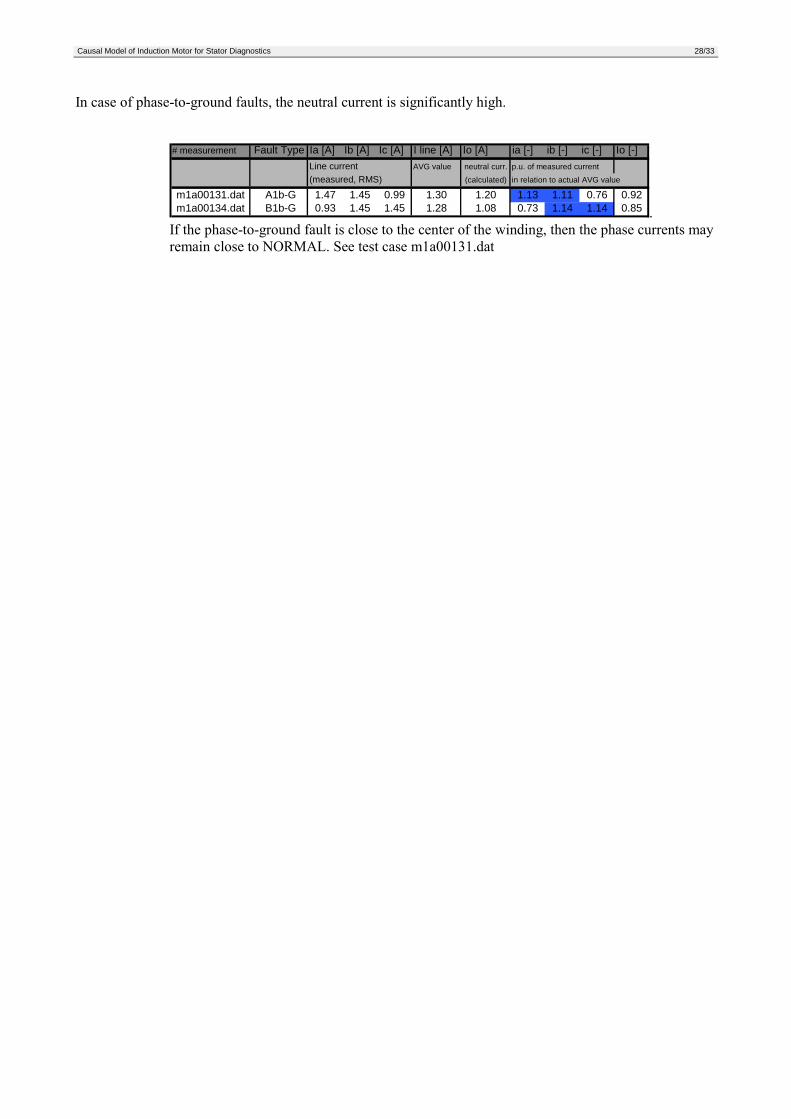
In case of phase-to-ground faults, the neutral current is significantly high.
# measurement Fault Type Ia [A] Ib [A] Ic [A] I line [A] Io [A] ia [-] ib [-] ic [-] Io [-]Line current AVG value neutral curr. p.u. of measured current(measured, RMS) (calculated) in relation to actual AVG value
m1a00131.dat A1b-G 1.47 1.45 0.99 1.30 1.20 1.13 1.11 0.76 0.92m1a00134.dat B1b-G 0.93 1.45 1.45 1.28 1.08 0.73 1.14 1.14 0.85 .
If the phase-to-ground fault is close to the center of the winding, then the phase currents mayremain close to NORMAL. See test case m1a00131.dat
Causal Model of Induction Motor for Stator Diagnostics 29/33
4 ConclusionThis report describes early stages of design of causal diagnostic model allowing for diagnostics of stator ininduction motors.
Basic requirement of this effort was to bring a simple induction motor diagnostics method that does notrequire expensive hardware and sensors.
We decided to design the first model under the following constraints:• The motor is connected to a symmetrical line.• The motor load is constant• There are no faults in rotor and bearings• There is only one stator fault in the motor
We tested the model in laboratory. The tests have proved that the model is able to reliably detect turn-to-turn,phase-to-phase, and phase-to-ground faults and even distinguish which phase is faulty. Unfortunately, wewere able to test the algorithm only using one motor loaded to 1/8 of its nominal load.
We consider the following tests are necessary to reliably prove full functionality of this approach:1 Test the algorithm on different motors with different power ratings.2 To test the algorithm under different loads of the motor3 To test the effect of non-symmetry of the input line
Causal Model of Induction Motor for Stator Diagnostics 30/33
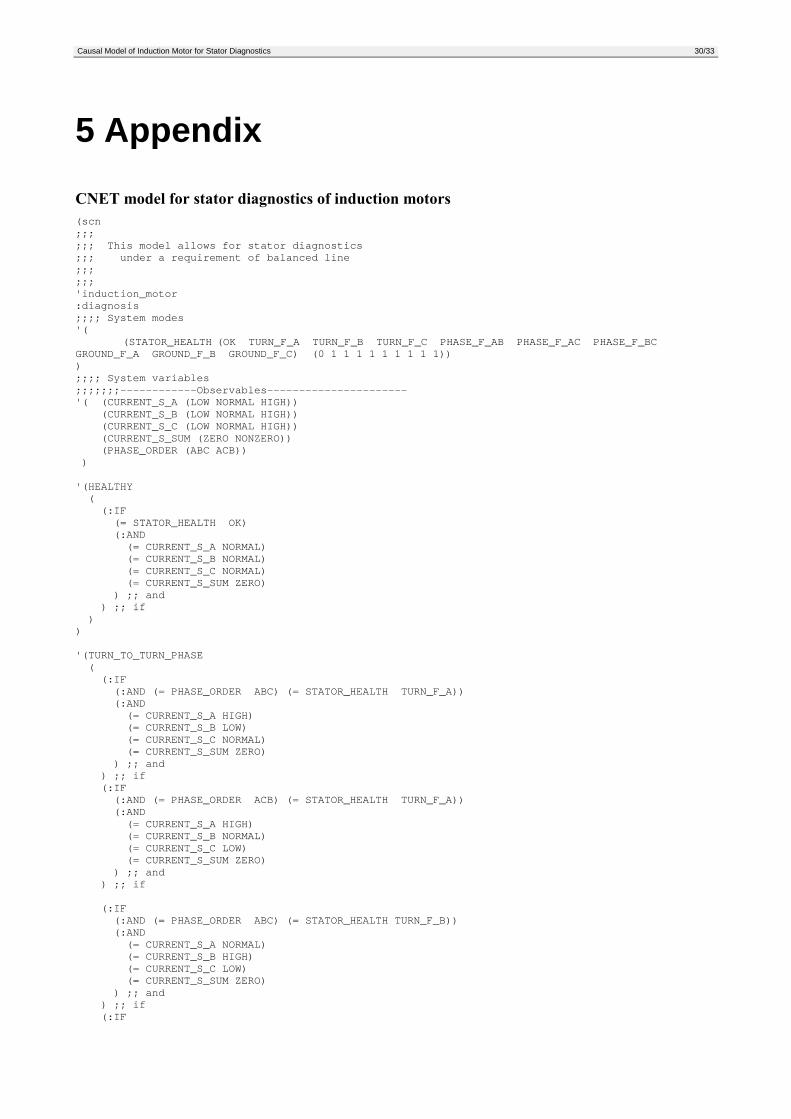
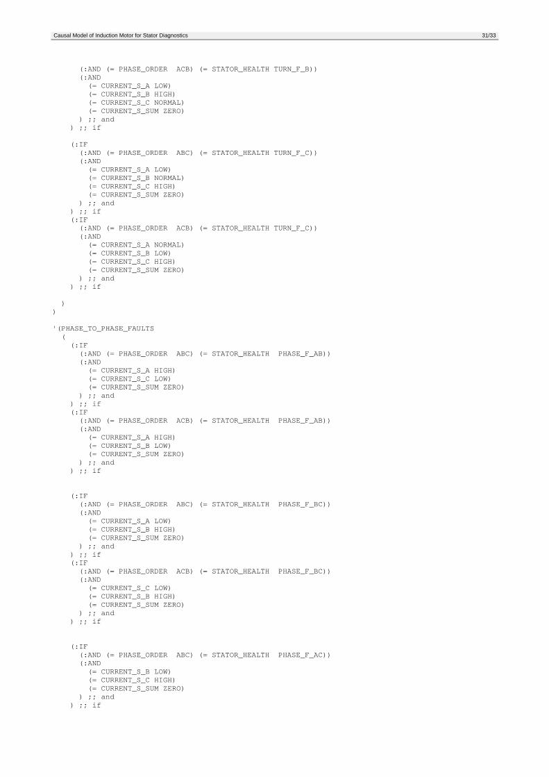
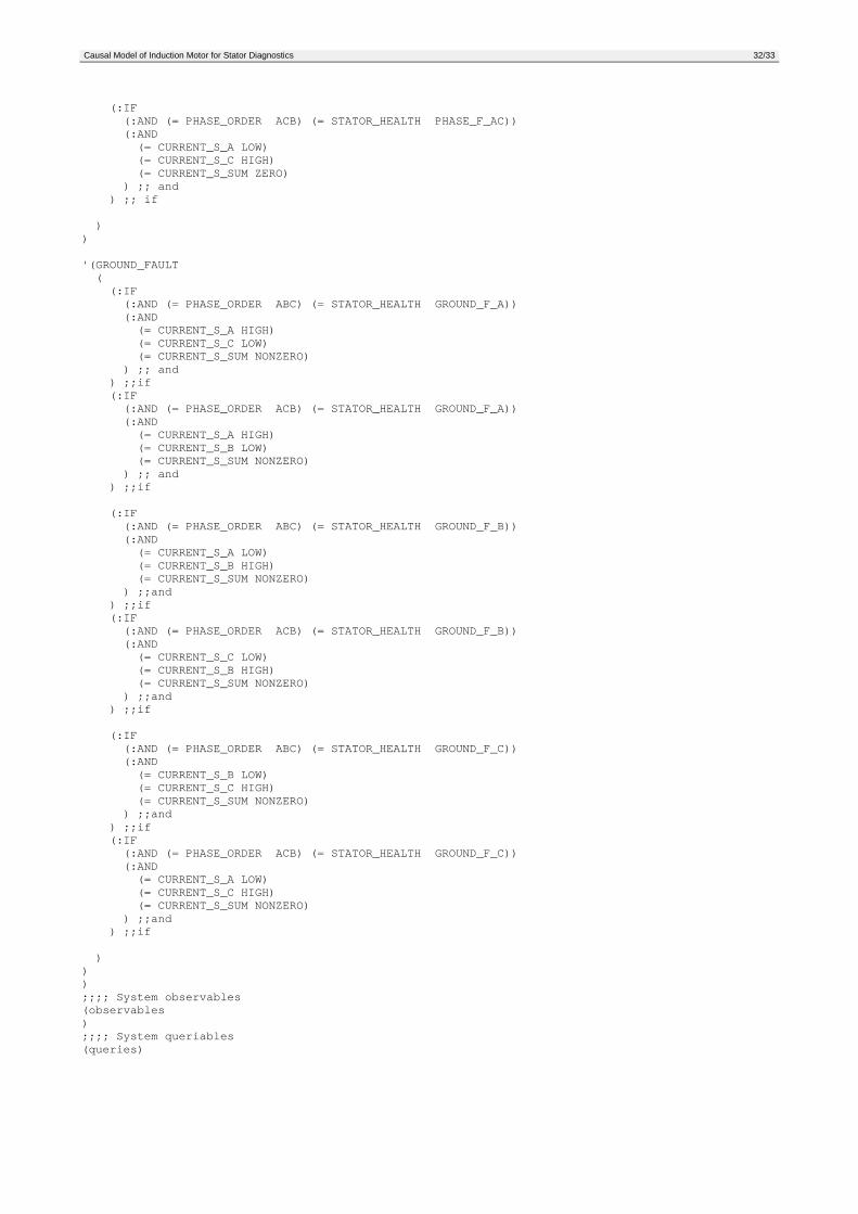
5 Appendix
CNET model for stator diagnostics of induction motors(scn;;;;;; This model allows for stator diagnostics;;; under a requirement of balanced line;;;;;;'induction_motor:diagnosis;;;; System modes'(
(STATOR_HEALTH (OK TURN_F_A TURN_F_B TURN_F_C PHASE_F_AB PHASE_F_AC PHASE_F_BCGROUND_F_A GROUND_F_B GROUND_F_C) (0 1 1 1 1 1 1 1 1 1)));;;; System variables;;;;;;;------------Observables----------------------'( (CURRENT_S_A (LOW NORMAL HIGH))
(CURRENT_S_B (LOW NORMAL HIGH))(CURRENT_S_C (LOW NORMAL HIGH))(CURRENT_S_SUM (ZERO NONZERO))(PHASE_ORDER (ABC ACB))
)
'(HEALTHY((:IF(= STATOR_HEALTH OK)(:AND(= CURRENT_S_A NORMAL)(= CURRENT_S_B NORMAL)(= CURRENT_S_C NORMAL)(= CURRENT_S_SUM ZERO)
) ;; and) ;; if
))
'(TURN_TO_TURN_PHASE((:IF(:AND (= PHASE_ORDER ABC) (= STATOR_HEALTH TURN_F_A))(:AND(= CURRENT_S_A HIGH)(= CURRENT_S_B LOW)(= CURRENT_S_C NORMAL)(= CURRENT_S_SUM ZERO)
) ;; and) ;; if(:IF(:AND (= PHASE_ORDER ACB) (= STATOR_HEALTH TURN_F_A))(:AND(= CURRENT_S_A HIGH)(= CURRENT_S_B NORMAL)(= CURRENT_S_C LOW)(= CURRENT_S_SUM ZERO)
) ;; and) ;; if
(:IF(:AND (= PHASE_ORDER ABC) (= STATOR_HEALTH TURN_F_B))(:AND(= CURRENT_S_A NORMAL)(= CURRENT_S_B HIGH)(= CURRENT_S_C LOW)(= CURRENT_S_SUM ZERO)
) ;; and) ;; if(:IF
Causal Model of Induction Motor for Stator Diagnostics 31/33
(:AND (= PHASE_ORDER ACB) (= STATOR_HEALTH TURN_F_B))(:AND(= CURRENT_S_A LOW)(= CURRENT_S_B HIGH)(= CURRENT_S_C NORMAL)(= CURRENT_S_SUM ZERO)
) ;; and) ;; if
(:IF(:AND (= PHASE_ORDER ABC) (= STATOR_HEALTH TURN_F_C))(:AND(= CURRENT_S_A LOW)(= CURRENT_S_B NORMAL)(= CURRENT_S_C HIGH)(= CURRENT_S_SUM ZERO)
) ;; and) ;; if(:IF(:AND (= PHASE_ORDER ACB) (= STATOR_HEALTH TURN_F_C))(:AND(= CURRENT_S_A NORMAL)(= CURRENT_S_B LOW)(= CURRENT_S_C HIGH)(= CURRENT_S_SUM ZERO)
) ;; and) ;; if
))
'(PHASE_TO_PHASE_FAULTS((:IF(:AND (= PHASE_ORDER ABC) (= STATOR_HEALTH PHASE_F_AB))(:AND(= CURRENT_S_A HIGH)(= CURRENT_S_C LOW)(= CURRENT_S_SUM ZERO)
) ;; and) ;; if(:IF(:AND (= PHASE_ORDER ACB) (= STATOR_HEALTH PHASE_F_AB))(:AND(= CURRENT_S_A HIGH)(= CURRENT_S_B LOW)(= CURRENT_S_SUM ZERO)
) ;; and) ;; if
(:IF(:AND (= PHASE_ORDER ABC) (= STATOR_HEALTH PHASE_F_BC))(:AND(= CURRENT_S_A LOW)(= CURRENT_S_B HIGH)(= CURRENT_S_SUM ZERO)
) ;; and) ;; if(:IF(:AND (= PHASE_ORDER ACB) (= STATOR_HEALTH PHASE_F_BC))(:AND(= CURRENT_S_C LOW)(= CURRENT_S_B HIGH)(= CURRENT_S_SUM ZERO)
) ;; and) ;; if
(:IF(:AND (= PHASE_ORDER ABC) (= STATOR_HEALTH PHASE_F_AC))(:AND(= CURRENT_S_B LOW)(= CURRENT_S_C HIGH)(= CURRENT_S_SUM ZERO)
) ;; and) ;; if
Causal Model of Induction Motor for Stator Diagnostics 32/33
(:IF(:AND (= PHASE_ORDER ACB) (= STATOR_HEALTH PHASE_F_AC))(:AND(= CURRENT_S_A LOW)(= CURRENT_S_C HIGH)(= CURRENT_S_SUM ZERO)
) ;; and) ;; if
))
'(GROUND_FAULT((:IF(:AND (= PHASE_ORDER ABC) (= STATOR_HEALTH GROUND_F_A))(:AND(= CURRENT_S_A HIGH)(= CURRENT_S_C LOW)(= CURRENT_S_SUM NONZERO)
) ;; and) ;;if(:IF(:AND (= PHASE_ORDER ACB) (= STATOR_HEALTH GROUND_F_A))(:AND(= CURRENT_S_A HIGH)(= CURRENT_S_B LOW)(= CURRENT_S_SUM NONZERO)
) ;; and) ;;if
(:IF(:AND (= PHASE_ORDER ABC) (= STATOR_HEALTH GROUND_F_B))(:AND(= CURRENT_S_A LOW)(= CURRENT_S_B HIGH)(= CURRENT_S_SUM NONZERO)
) ;;and) ;;if(:IF(:AND (= PHASE_ORDER ACB) (= STATOR_HEALTH GROUND_F_B))(:AND(= CURRENT_S_C LOW)(= CURRENT_S_B HIGH)(= CURRENT_S_SUM NONZERO)
) ;;and) ;;if
(:IF(:AND (= PHASE_ORDER ABC) (= STATOR_HEALTH GROUND_F_C))(:AND(= CURRENT_S_B LOW)(= CURRENT_S_C HIGH)(= CURRENT_S_SUM NONZERO)
) ;;and) ;;if(:IF(:AND (= PHASE_ORDER ACB) (= STATOR_HEALTH GROUND_F_C))(:AND(= CURRENT_S_A LOW)(= CURRENT_S_C HIGH)(= CURRENT_S_SUM NONZERO)
) ;;and) ;;if
)));;;; System observables(observables);;;; System queriables(queries)
Causal Model of Induction Motor for Stator Diagnostics 33/33
6 References[1] Alger, P. L. : The Nature of Induction Machines, Gordon & Breach Science Publishers, New York 1965[2] Chapman, S. J. : Electric Machinery Fundamentals, McGraw-Hill, New York, 1985, ISBN 0-07-
010662-2[3] Ryba, J. : Induction motor diagnostics, Praha 1997, Research Report, Rockwell Automation AT Prague
Labs[4] Hejda, P. - Červinka, O. : CNET Manual, Praha 1999, Research Report, Rockwell Automation AT
Prague Labs[5] Melero, M. G. - Cabanas, M. F. : Electromagnetic torque harmonics for on-line interturn short circuits
detection in squirrel cage induction motor, Conference EPE’99, Lausanne, 1999