Embed Size (px)
Citation preview

Catalog
HG 11.05 ·
Edition 2017
siemens.com/3AH5
3AH5 Vacuum Circuit-Breakers Medium-Voltage Equipment

2 3AH5 Vacuum Circuit-Breakers · Siemens HG 11.05 · 2017
R-HG
11-3
73.ti
f

1
2
3
4
33AH5 Vacuum Circuit-Breakers · Siemens HG 11.05 · 2017
Description 5General 6
Construction and mode of operation 7
Standards 8
Maintenance-free design, ambient conditions, current carrying capacity and dielectric strength 9
Product range overview and basic equipment 10
Equipment Selection 11Ordering data and configuration example 12
Selection of basic types, circuit-breakers 13
Selection of secondary equipment 15
Selection of additional equipment 20
Accessories and spare parts 21
Technical Data 23Electrical data, dimensions, weights and dimension drawings 24
Operating times, short-circuit protection of motors, consumption data of releases 31
Circuit diagrams 32
Annex 33Inquiry form 34
Configuration instructions 35
Configuration aid Foldout page
Contents Page
3AH5 Vacuum Circuit-Breakers Medium-Voltage EquipmentCatalog HG 11.05 · 2017
Invalid: Catalog HG 11.05 · 2010
Contents
The products and systems described in this catalog are manufactured and sold according to a certified management system (acc. to ISO 9001, ISO 14001 and BS OHSAS 18001).

4 3AH5 Vacuum Circuit-Breakers · Siemens HG 11.05 · 2017
R-HG
11-3
57.ti
f

1
53AH5 Vacuum Circuit-Breakers · Siemens HG 11.05 · 2017
Description 5 General 6
Construction and mode of operation 7
Pole assemblies 7
Operating mechanism box 7
Operating mechanism 7
Trip-free mechanism 7
Releases 8
Closing 8
Interlocking 8
Standards 8
Maintenance-free design, ambient conditions, current carrying capacity and dielectric strength 9
Product range overview and basic equipment 10
Contents Page
R-HG
11-1
74.ti
f
Industrial application: Refinery
DescriptionContents
1
6 3AH5 Vacuum Circuit-Breakers · Siemens HG 11.05 · 2017
3AH5 standard circuit-breaker from 12 to 36 kV – The Economical
3AH5 vacuum circuit-breakers control all switching duties in medium-voltage systems. They are applicable for opera-tion of e.g. overhead lines, cables, transformers,
R-HG
11-2
01.e
ps
R-HG
11-1
85.e
ps
3AH5 – the universal circuit-breaker in the product range
generators, capacitors, filter circuits, motors and reactors. Here, small short-circuit ratings in distribution systems face high breaking currents in industrial systems.
The 3AH5 vacuum circuit-breaker is a real all-round device in its field of application. With its compact dimensions, it fits in all customary switchgear types. The comprehensive variety of types with different normal currents and short-circuit currents
DescriptionGeneral
as well as various pole-centre distances for voltage levels from 12 kV to 36 kV enables its universal application for all medium-voltage requirements.

1
73AH5 Vacuum Circuit-Breakers · Siemens HG 11.05 · 2017
The 3AH5 vacuum circuit-breaker consists of the pole assem-blies (1) and the operating mechanism box (2). The pole as-semblies are fixed to the operating mechanism box via post insulators (3). The switching movement is transferred by means of operating rods (4) and levers.
Pole assemblies
The pole assemblies consist of the vacuum interrupters (5) and the interrupter supports. The vacuum interrupters are air-insulated and freely accessible. This makes it possible to clean the insulating parts easily in adverse ambient condi-tions. The vacuum interrupter is rigidly fixed to the upper interrupter support (6). The lower part of the interrupter is guided in the lower interrupter support (7), allowing axial movement. The braces (8) absorb the external forces result-ing from switching operations and the contact pressure.
Operating mechanism box
The whole operating mechanism with releases, auxiliary switches, indicators and actuating devices is accommodated in the operating mechanism box. The extent of the second-ary equipment depends on the case of application and offers a multiple variety of options in order to meet almost every requirement.
Operating mechanism
For circuit-breaker operation, both spring-operated and stored-energy mechanisms are available. With manual spring-operated mechanisms, the closing process takes place automatically after manual charging of the closing spring. The opening or contact springs are charged simultaneously during the closing operation, which means that a stored energy mechanism is available for the opening operation.
With motor or manual operating stored-energy mechanisms, the closing spring is either charged electrically or manually. It latches tight at the end of the charging process and serves as an energy store.
To close the breaker, the closing spring can be unlatched either mechanically by means of the local “ON” pushbutton or electrically by remote control. The closing spring charges the opening or contact pressure springs as the breaker clos-es. The now discharged closing spring will be charged again automatically by the mechanism motor or manually. Then the operating sequence OPEN-CLOSE-OPEN is stored in the springs.
Trip-free mechanism
3AH5 vacuum circuit-breakers have a trip-free mechanism according to IEC 62271-100. In the event of an opening com-mand being given after a closing operation has been initiated, the moving contacts return to the open position and remain there even if the closing command is sustained. This means that the contacts of the vacuum circuit-breakers are momen-tarily in the closed position, which is permissible according to IEC 62271-100.
Circuit-breaker structure
1 Pole assembly
2 Operating mechanism box
3 Post insulator
4 Operating rod
5 Vacuum interrupter
6 Upper interrupter support
7 Lower interrupter support
8 Brace
Front view
Open operating mechanism box
R-HG
11-1
86.ti
fR-
HG11
-187
.tif
DescriptionConstruction and mode of operation

1
8 3AH5 Vacuum Circuit-Breakers · Siemens HG 11.05 · 2017
An electrical closing lock-out prevents unpermissible clos-ing of the circuit-breaker. The closing lock-out releases the operation of the circuit-breaker when auxiliary voltage is available, and blocks both local manual closing and remote electrical closing mechanically when there is no auxiliary voltage available.
The operating voltage of the electrical closing lock-out is the same as that of the closing solenoid. If constant CLOSE and OPEN commands are present at the vacuum circuit-breaker at the same time, the vacuum circuit-breaker will return to the open position after closing. It remains in this position until a new CLOSE command is given. In this manner, continuous closing and opening (= “pumping”) is prevented.
Interlocking
Mechanical interlocking for stored-energy mechanisms
To interlock circuit-breaker trucks, withdrawable parts or dis-connectors according to the switch position, the stored en-ergy mechanisms of 3AH5 circuit-breakers can be equipped with a mechanical interlocking. A sensor at the switchgear checks the position of the circuit-breaker and prevents the open circuit-breaker in a reliable way from being closed me-chanically and electrically.
Electrical interlocking
The vacuum circuit-breakers can be integrated in electro-magnetic feeder or switchgear interlocks. In case of electrical interlocking, the disconnector or its operating mechanism is equipped with a magnetic lock-out mechanism. This mecha-nism is controlled by an auxiliary contact of the circuit-breaker, so that the disconnector can only be operated when the circuit-breaker is open. On the other hand, the vacuum circuit-breaker is also controlled by the disconnector or its operating mechanism, so that it can only be closed when the disconnector is in an end position. For this purpose, the circuit-breaker operating mechanism must be equipped with a closing lock-out (see “Closing”).
Standards
3AH5 vacuum circuit-breakers conform to the following standards:• IEC 62271-100 (former IEC 60056)
• IEC 62271-1 (former IEC 60694)
• VDE 0671(former VDE 0670 Part 100 and VDE 0670 Part 1000)
All 3AH5 vacuum circuit-breakers fulfil the endurance classes E2, M2 and C2 according to IEC 62271-100.
Releases
A release is a device which transfers electrical commands from an external source, such as a control room, to the latch-ing mechanism of the vacuum circuit-breaker so that it can be opened or closed. Apart from the closing solenoid, the maximum possible equipment is one shunt release and an-other release to be selected at will. For release combinations, refer to page 15.
• The closing solenoid unlatches the charged closing spring of the vacuum circuit-breaker, closing it by electrical means. It is suitable for DC or AC voltage.
• Shunt releases are used for automatic tripping of vacuum circuit-breakers by suitable protection relays and for deliber-ate tripping by electrical means. They are intended for con-nection to an external power supply (DC or AC voltage) but, in special cases, may also be connected to a voltage trans-former for manual operation.
• Current-transformer operated releases comprise a stored energy mechanism, an unlatching mechanism and an elec-tromagnetic system. They are used when there is no external source of auxiliary power (e.g. a battery). Tripping is effected by means of a protection relay (e.g. overcurrent time protec-tion) acting on the current-transformer operated release. When the tripping current is exceeded (= 90 % of the rated normal current of the c.t.-operated release), the latch of the energy store, and thus opening of the circuit-breaker, is re-leased.
• Undervoltage releases comprise a stored-energy mecha-nism, an unlatching mechanism and an electromagnetic system which is permanently connected to the secondary or auxiliary voltage while the vacuum circuit-breaker is closed. If the voltage falls below a predetermined value, unlatching of the release is enabled and the circuit-breaker is opened via the stored-energy mechanism.
The deliberate tripping of the undervoltage release generally takes place via an NC contact in the tripping circuit or via an NO contact by short-circuiting the magnet coil. With this type of tripping, the short-circuit current is limited by the built-in resistors. Undervoltage releases can also be connected to voltage transformers. When the operating voltage drops to impermissibly low levels, the circuit-breaker is tripped auto-matically.
For delayed tripping, the undervoltage release can be com-bined with energy stores.
Closing
In the standard version of the stored-energy mechanisms, 3AH5 vacuum circuit-breakers can be remote-closed electri-cally. They can also be closed locally by mechanical unlatch-ing of the closing spring via pushbutton. With spring oper-ated mechanisms, closing obligatory takes place after the charging process.
DescriptionConstruction and mode of operation, standards

1
93AH5 Vacuum Circuit-Breakers · Siemens HG 11.05 · 2017
Maintenance-free design
The 3AH5 vacuum circuit-breakers are maintenance-free:• Under normal ambient conditions according to IEC 62271-1
(former IEC 60694).• Up to 10,000 operating cycles,
– no relubrication, no readjustment required – and within their tolerances, the characteristics are independent of the switching rate or of standing times without switching operations.
Ambient conditions
The vacuum circuit-breakers are designed for the normal operating conditions defined in IEC 62271-100.
Condensation can occasionally occur under the ambient conditions shown opposite. 3AH5 vacuum circuit-breakers are suitable for use in the following climatic classes accord-ing to IEC 60721, Part 3-3:
Climatic ambient conditions: Class 3K4 1) Biological ambient conditions: Class 3B1 Mechanical ambient conditions: Class 3M2 Chemically-active substances: Class 3C2 2) Mechanically-active substances: Class 3S2 3)
1) Low temperature limit: – 5 °C2) Without icing and wind-driven precipitation3) Restriction: Clean insulation parts
Current carrying capacity (see diagram)
The rated normal currents specified in the opposite diagram have been defined according to IEC 62271-100 for an ambi-ent air temperature of + 40 °C and apply to open switchgear. For enclosed switchgear the data of the switchgear manu-facturer applies. At ambient air temperatures below + 40 °C, higher normal currents can be carried.
Characteristics curve 1 = Rated normal current 800 A Characteristics curve 2 = Rated normal current 1250 A Characteristics curve 3 = Rated normal current 2000 A Characteristics curve 4 = Rated normal current 2500 A
Dielectric strength
The dielectric strength of air insulation decreases with increasing altitude due to low air density. According to IEC 62271-1, the values of the rated lightning impulse with-stand voltage and the rated short-duration power frequency withstand voltage specified in the chapter “Technical Data” apply to a site altitude of 1000 m above sea level. For an al-titude above 1000 m, the insulation level must be corrected according to the opposite diagram. The characteristic shown applies to both rated withstand voltages.
To select the devices, the following applies: U ≥ U0 x Ka
U Rated withstand voltage under reference atmosphereU0 Rated withstand voltage requested for the place of installationKa Altitude correction factor according to the opposite diagram
Example
For a requested rated lightning impulse withstand voltage of 75 kV at an altitude of 2500 m, an insulation level of 90 kV under reference atmosphere is required as a minimum:
90 kV ≥ 75 kV x 1.2
DescriptionMaintenance-free design, ambient conditions, current carrying capacity and dielectric strength

1
10 3AH5 Vacuum Circuit-Breakers · Siemens HG 11.05 · 2017
Product range overview 3AH5
Ratedvoltage
Ratedshort-circuit
breaking current
Rated normal current (A)
800 1250 2000 2500
Pole-centre distance (mm)
kV kA 160 210 275 160 210 275 350 210 275 350 210 275
12 13.1 n n
16 n n n n
20 n n n n n
25 n n n n n n
31.5 n n n n
17.5 25 n n n n n31.5 n n n n
24 16 n n n n
20 n n n n n n
25 n n n n
36 16 n n
25 n n n
n Available design
Basic equipment
In the basic version, the 3AH5 is equipped with a manual spring-operated mechanism. The following overview shows the alternatively selectable or additional equipment, as well as the possibility of designing the switching device with stored- energy mechanisms.
Equipment features for the different types of operating mechanisms
Typ
e o
f o
per
atin
gm
ech
anis
m
Clo
sin
g s
ole
no
id
Elec
tric
alcl
osi
ng
lock
-ou
t 3
)
1st
sh
un
t re
leas
e
2n
d r
elea
se
Co
un
ter
Cir
cuit
-bre
aker
trip
pin
g s
ign
al
Au
xilia
ry s
wit
ch2
NO
+2
NC
Au
xilia
ry s
wit
ch6
NO
+6
NC
Au
xilia
ry s
wit
ch1
2N
O+
12
NC
Wit
ho
ut
term
inal
str
ip
24
-po
lete
rmin
al s
trip
24
-po
lep
lug
co
nn
ecti
on
64
-po
lep
lug
co
nn
ecti
on
Mec
han
ical
inte
rlo
ckin
g
Manual spring operatedmechanism 1)
– – n n X X – X X X –
Manual operating stored-energy mechanism 1)
n n X X – X X X –
Motor operating stored-energy mechanism 2)
n n n – X X 4) – X X X
DescriptionProduct range overview and basic equipment
For the endurance class C2, all circuit-breakers fulfil the following values according to IEC 62271-100
Line Cable Single capacitor bank Back-to-back capacitor bank 1)
Rated voltage Rated line-charging breaking current
Rated cable-charging breaking current
Rated single capacitor bank breaking current 2)
Rated back-to-back capacitor bank breaking
current
Frequency of the inrush current
Ur kV, r.m.s.
Il A, r.m.s.
Ic A, r.m.s.
Isb A, r.m.s.
Ibb A, r.m.s.
fbl Hz
12 10 25 400 400 425017.5 10 31.5 400 400 425024 10 31.5 400 400 425036 10 50 400 400 4250
1) Rated back-to-back capacitor bank making current for a back-to-back capacitor bank – see chapter 3: Technical data2) The capacitive switching capacity of the circuit-breaker is 0.7xIr above the standard specification.
n Basic equipment X Optionally selectable basic equipment Selectable additional equipment – Not available
1) With manual operating mechanism, always with hand crank2) With anti-pumping device3) From pole-centre distance ≥ 210mm4) Only with 64-pole plug

2
113AH5 Vacuum Circuit-Breakers · Siemens HG 11.05 · 2017
Equipment Selection 11 Ordering data and configuration example 12
Selection of basic types, circuit-breakers
Voltage level 12 kV 13
Voltage level 17.5 kV 13
Voltage level 24 kV 14
Voltage level 36 kV 14
Selection of secondary equipment
Release combination 15
Operating voltage, closing solenoid 16
Operating voltage, 1st shunt release 16
Operating voltage, 2nd release 17
Counter and circuit-breaker tripping signal 18
Operating voltage for operating mechanism/ type of operating mechanism 18
Auxiliary switch, secondary connection, interlocking 19
Languages and frequency 19
Additional equipment 20
Accessories and spare parts
Rating plate 21
Accessories catalog 21
Contents Page
R-HG
11-1
84.ti
fR-
HG11
-188
.tif
3AH5 135-6 vacuum circuit-breaker
3AH5 204-1 vacuum circuit-breaker
Equipment SelectionContents
n Basic equipment X Optionally selectable basic equipment Selectable additional equipment – Not available

2
12 3AH5 Vacuum Circuit-Breakers · Siemens HG 11.05 · 2017
Order number structure
The 3AH5 vacuum circuit-breakers consist of a primary and a secondary part. The relevant data make up the 16-digit order number. The primary part covers the main electrical data of the circuit-breaker poles. The secondary part covers the auxiliary devices which are necessary for operating and controlling the vacuum circuit-breaker.
Order codes
Individual equipment versions, marked with “9” or “Z” in the 9th to 16th position, are explained more in detail by a 3-digit order code. Several order codes can be added to the order number in succession and in any sequence.
Special versions («)
In case of special versions, “-Z” is added to the order num-ber and a descriptive order code follows. If several special versions are required, the suffix “-Z” is listed only once. If a requested special version is not in the catalog and can there-fore not be ordered via order code, it has to be identified with Y 9 9 after consultation. The agreement here to is made directly between your responsible sales partner and the order processing department in the Switchgear Factory Berlin.
Equipment SelectionOrder number structure and configuration example
a: alphabetical n: numerical
Position: 1 2 3 4 5 6 7 – 8 9 10 11 12 – 13 14 15 16 Order codes
Order No.: 3 A H 5 n n n – n a a n n – n a a n – « n n n
Primary part1st position Superior group
Switching devices
2nd position Main groupCircuit-breaker
3rd position SubgroupCircuit-breaker type series
4th to 8th position Basic equipment Design and ratings primary part
Secondary part9th to 16th position Secondary equipment
Operating mechanism, releases, operating voltages and further auxiliary equipment
Order codesGroup of 3 after the Order No.Format: a n a
Special versions («)Initiated with “-Z”Group of 3 after the Order No.Format: a n n
Configuration example
In order to simplify the selection of the correct order number for the requested circuit-breaker type, you will find a configuration example on each page of the chapter “Equipment Selection”. For the selection of the secondary part, always the last example of the primary part was taken over and continued, so that at the end of the equipment selection (page 20) a completely configured circuit-breaker results as an example.
On the foldout page we offer a configuring aid. Here you can fill in the order number you have determined for your circuit-breaker.
Example for Order No.: 3 A H 5 1 2 2 – 1 n n n n – n n n n
Order codes:

2
133AH5 Vacuum Circuit-Breakers · Siemens HG 11.05 · 2017
Example for Order No.: 3 A H 5 2 1 4 – 6 n n n n – n n n n – Z
Order codes: E 1 3
12 kV50/60 Hz
Position:
Order No.:
1 2 3 4 5 6 7 – 8 9 10 11 12 – 13 14 15 16 Order codes
3 A H 5 n n n – n n n n n – n n n n – « n n n
Rate
d v
olt
age
Rate
d li
gh
tnin
g im
pu
lse
wit
hst
and
vo
ltag
e
Rate
d s
ho
rt-d
ura
tio
np
ow
er-f
req
uen
cyw
ith
stan
d v
olt
age
Rate
d s
ho
rt-c
ircu
itb
reak
ing
cu
rren
tat
36
% D
C c
om
po
nen
t
Rate
d s
ho
rt-c
ircu
itm
akin
g c
urr
ent
(at
50
/60
Hz)
Pole
-cen
tre
dis
tan
ce
Rate
d n
orm
al c
urr
ent
See
pag
e 1
5
See
pag
e 1
6
See
pag
e 1
6
See
pag
e 1
7
See
pag
e 1
8
See
pag
e 1
8
See
pag
e 1
9
See
pag
e 1
9
See
pag
e 2
0
Ur Up Ud ISC Ima Ir
kV kV kV kA kA mm A
12 75 28 13.1 33/34 160 800 3 A H 5 1 2 1 – 1
210 800 3 A H 5 1 3 1 – 1
16 40/42 160 800 3 A H 5 1 2 2 – 1
1250 3 A H 5 1 2 2 – 2
210 800 3 A H 5 1 3 2 – 1
1250 3 A H 5 1 3 2 – 2
20 50/52 160 800 3 A H 5 1 2 3 – 1
1250 3 A H 5 1 2 3 – 2
210 800 3 A H 5 1 3 3 – 1
1250 3 A H 5 1 3 3 – 2
2000 3 A H 5 1 3 3 – 4
25 63/65 160 800 3 A H 5 1 4 4 – 1
1250 3 A H 5 1 4 4 – 2
210 800 3 A H 5 1 5 4 – 1
1250 3 A H 5 1 5 4 – 2
2000 3 A H 5 1 3 4 – 4
2500 3 A H 5 1 3 4 – 6
31.5 80/82 160 1250 3 A H 5 1 2 5 – 2
210 1250 3 A H 5 1 3 5 – 2
2000 3 A H 5 1 3 5 – 4
2500 3 A H 5 1 3 5 – 6
Special version Ud = 42 kV (available for all 12 kV ≥ 25 kA circuit-breakers) – Z E 1 3
17.5 kV50/60 Hz
Ur Up Ud ISC Ima Ir
kV kV kV kA kA mm A
17.5 95 38 25 63/65 160 800 3 A H 5 2 0 4 – 1
1250 3 A H 5 2 0 4 – 2
210 800 3 A H 5 2 1 4 – 1
1250 3 A H 5 2 1 4 – 2
2500 3 A H 5 2 1 4 – 6
31.5 80/82 160 1250 3 A H 5 2 0 5 – 2
210 1250 3 A H 5 2 1 5 – 2
2000 3 A H 5 2 1 5 – 4
2500 3 A H 5 2 1 5 – 6
Special version Ud = 42 kV (available for all 17.5 kV circuit-breakers) – Z E 1 3
Configuration example
3AH5 vacuum circuit-breaker 3 A H 5
Rated voltage Ur= 17.5 kV
Rated short-circuit breaking current Isc = 25 kA
Rated normal current Ir = 2500 A
Pole-centre distance = 210 mm
Special version Ud = 42 kV 2 1 4 – 6 – Z E 1 3
Equipment SelectionSelection of basic types, circuit-breakers

2
14 3AH5 Vacuum Circuit-Breakers · Siemens HG 11.05 · 2017
Example for Order No.: 3 A H 5 3 1 4 – 4 n n n n – n n n n
Order codes:
24 kV50/60 Hz
1 2 3 4 5 6 7 – 8 9 10 11 12 – 13 14 15 16 Order codes
3 A H 5 n n n – n n n n n – n n n n – « n n n
Rate
d v
olt
age
Rate
d li
gh
tnin
g im
pu
lse
wit
hst
and
vo
ltag
e
Rate
d s
ho
rt-d
ura
tio
np
ow
er-f
req
uen
cyw
ith
stan
d v
olt
age
Rate
d s
ho
rt-c
ircu
itb
reak
ing
cu
rren
tat
36
% D
C c
om
po
nen
t
Rate
d s
ho
rt-c
ircu
itm
akin
g c
urr
ent
(at
50
/60
Hz)
Pole
-cen
tre
dis
tan
ce
Rate
d n
orm
al c
urr
ent
See
pag
e 1
5
See
pag
e 1
6
See
pag
e 1
6
See
pag
e 1
7
See
pag
e 1
8
See
pag
e 1
8
See
pag
e 1
9
See
pag
e 1
9
See
pag
e 2
0
Ur Up Ud ISC Ima Ir
kV kV kV kA kA mm A
24 125 50 16 40/42 210 800 3 A H 5 2 7 2 – 1
1250 3 A H 5 2 7 2 – 2
275 800 3 A H 5 2 8 2 – 1
1250 3 A H 5 2 8 2 – 2
20 50/52 210 1250 3 A H 5 2 7 3 – 2
2000 3 A H 5 2 7 3 – 4
2500 3 A H 5 2 7 3 – 6
275 1250 3 A H 5 2 8 3 – 2
2000 3 A H 5 2 8 3 – 4
2500 3 A H 5 2 8 3 – 6
25 63/65 210 1250 3 A H 5 2 7 4 – 2
2500 3 A H 5 2 7 4 – 6
275 1250 3 A H 5 2 8 4 – 22500 3 A H 5 2 8 4 – 6
36 kV50/60 Hz
Ur Up Ud ISC Ima Ir
kV kV kV kA kA mm A
36 170 70 16 40/42 275 1250 3 A H 5 3 2 2 – 2
350 1250 3 A H 5 3 1 2 – 2
25 63/65 275 1250 3 A H 5 3 2 4 – 2
350 1250 3 A H 5 3 1 4 – 22000 3 A H 5 3 1 4 – 4
Configuration example
3AH5 vacuum circuit-breaker 3 A H 5
Rated voltage Ur = 36 kV
Rated short-circuit breaking current ISC = 25 kA
Rated normal current Ir = 2000 A
Pole-centre distance = 350 mm 3 1 4 – 4
Position:
Order No.:
Equipment SelectionSelection of basic types, circuit-breakers

2
153AH5 Vacuum Circuit-Breakers · Siemens HG 11.05 · 2017
Equipment SelectionSelection of secondary equipment
Example for Order No.: 3 A H 5 3 1 4 – 4 U n n n – n n n n – Z
Order codes: A 4 6
9th position Position:
Order No.:
1 2 3 4 5 6 7 – 8 9 10 11 12 13 14 15 16 Order codes
Release combination 3 A H 5 n n n – n n n n n – n n n n – « n n n
1st
sh
un
t re
leas
e
2n
d s
hu
nt
rele
ase
Un
der
volt
age
rele
ase
C.t
.-o
per
ated
rel
ease
0.5
A
C.t
.-o
per
ated
rel
ease
1.0
A
C.t
.-o
per
ated
rel
ease
wit
h t
rip
pin
g p
uls
e≥
0.1
Ws
(10
Ω)
C.t
.-o
per
ated
rel
ease
wit
h t
rip
pin
g p
uls
e≥
0.1
Ws
(20
Ω)
See
pag
e 1
6
See
pag
e 1
6
See
pag
e 1
7
See
pag
e 1
8
See
pag
e 1
8
See
pag
e 1
9
See
pag
e 1
9
See
pag
e 2
0
n M
n n N
n n R
n n U
n n U – Z A 4 6
n n V
n n V – Z A 4 5
Configuration example
3AH5 vacuum circuit-breaker 3 A H 5
(Ur = 36 kV, ISC = 25 kA, Ir = 2000 A, pole-centre distance = 350 mm) 3 1 4 – 4
1st shunt release; c.t.-operated release
with a rated normal current of 1.0 A U – Z A 4 6

2
16 3AH5 Vacuum Circuit-Breakers · Siemens HG 11.05 · 2017
Equipment SelectionSelection of secondary equipment
Example for Order No.: 3 A H 5 3 1 4 – 4 U C 2 n – n n n n – Z
Order codes: A 4 6
10th position Position: 1 2 3 4 5 6 7 – 8 9 10 11 12 – 13 14 15 16 Order codes
Operating voltage of the closing solenoid Order No.: 3 A H 5 n n n – n n n n n – n n n n – « n n n
Standard voltages Special voltages
See
pag
e 1
7
See
pag
e 1
8
See
pag
e 1
8
See
pag
e 1
9
See
pag
e 1
9
See
pag
e 2
0
To be observed for selection!
• Manual spring-operat.mechan. generally without closing solenoid (A)
• Man. operat. stored-energy mechan. option. with closing solenoid (A – Z)
• Motor op. stored-energy mech. generally with closing solenoid (B – Z)
Without closing solenoid A
24 V DC B
48 V DC C
60 V DC D
110 V DC E
220 V DC F
100 V AC 50 / 60 Hz 1) H
110 V AC 50 / 60 Hz 1) J
230 V AC 50 / 60 Hz 1) K
30 V DC Z With order code K 1 A
32 V DC Z With order code K 1 B
120 V DC Z With order code K 1 C
125 V DC Z With order code K 1 D
127 V DC Z With order code K 1 E
240 V DC Z With order code K 1 F
120 V AC 50 / 60 Hz 1) Z With order code K 1 K
125 V AC 50 / 60 Hz 1) Z With order code K 1 L
240 V AC 50 / 60 Hz 1) Z With order code K 1 M
11th positionOperating voltage of the 1st shunt release
Standard voltages Special voltages
24 V DC 1
48 V DC 2
60 V DC 3
110 V DC 4
220 V DC 5
100 V AC 50 / 60 Hz 1) 6
110 V AC 50 / 60 Hz 1) 7
230 V AC 50 / 60 Hz 1) 8
30 V DC 9 With order code L 1 F
32 V DC 9 With order code L 1 B
120 V DC 9 With order code L 1 C
125 V DC 9 With order code L 1 D
127 V DC 9 With order code L 1 E
240 V DC 9 With order code L 1 F
120 V AC 50 / 60 Hz 1) 9 With order code L 1 K
125 V AC 50 / 60 Hz 1) 9 With order code L 1 L
240 V AC 50 / 60 Hz 1) 9 With order code L 1 M
1) The AC frequency 50 or 60 Hz is selected at the 16th position of the order number together with the language (see page 19)
Configuration example
3AH5 vacuum circuit-breaker 3 A H 5
(Ur = 36 kV, ISC = 25 kA, Ir = 2000 A, pole-centre distance = 350 mm) 3 1 4 – 4 U
Operating voltage of the closing solenoid 48 V DC (manual operating stored-energy mechanism) C
Operating voltage of the 1st shunt release 48 V DC 2

2
173AH5 Vacuum Circuit-Breakers · Siemens HG 11.05 · 2017
12th position Position: 1 2 3 4 5 6 7 – 8 9 10 11 12 – 13 14 15 16 Order codes
Operating voltage of the 2nd release Order No.: 3 A H 5 n n n – n n n n n – n n n n – « n n n
Standard voltages Special voltages
See
pag
e 1
8
See
pag
e 1
8
See
pag
e 1
9
See
pag
e 1
9
See
pag
e 2
0
Without, or c.t.-operated release 0
24 V DC 1
48 V DC 2
60 V DC 3
110 V DC 4
220 V DC 5
100 V AC 50 / 60 Hz 1) 6
110 V AC 50 / 60 Hz 1) 7
230 V AC 50 / 60 Hz 1) 8
30 V DC 9 With order code M 1 A
32 V DC 9 With order code M 1 B
120 V DC 9 With order code M 1 C
125 V DC 9 With order code M 1 D
127 V DC 9 With order code M 1 E
240 V DC 9 With order code M 1 F
120 V AC 50 / 60 Hz 1) 9 With order code M 1 K
125 V AC 50 / 60 Hz 1) 9 With order code M 1 L
240 V AC 50 / 60 Hz 1) 9 With order code M 1 M
Special version
To operate the 2nd release as an undervoltage release on an
energy store type AN1902- (for DC) or AN1901-2 (for AC),
both make Bender, the operating voltage must be defined –
and whether the energy store will be provided by the customer
or included in the scope of supply.
Energy store
TypeIn the scopeof supply
60 V DC AN 1902- no 9 With order code M 2 D
110 V DC AN 1902- no 9 With order code M 2 E
220 V DC AN 1902- no 9 With order code M 2 F
100 V /110 V /230 V AC AN 1901-2 no 9 With order code M 2 G
60 V DC AN 1902- yes 9 With order code M 3 D
110 V DC AN 1902- yes 9 With order code M 3 E
220 V DC AN 1902- yes 9 With order code M 3 F
100 V /110 V /230 V AC AN 1901-2 yes 9 With order code M 3 G
1) The AC frequency 50 or 60 Hz is selected at the 16th position of the order number together with the language (see page 19)
Configuration example
3AH5 vacuum circuit-breaker 3 A H 5
(Ur = 36 kV, ISC = 25 kA, Ir = 2000 A, pole-centre distance = 350 mm) 3 1 4 – 4 U C 2
2nd release as c.t.-operated release with a rated normal current of 1.0 A 0
Example for Order No.: 3 A H 5 3 1 4 – 4 U C 2 0 – n n n n – Z
Order codes: A 4 6
Equipment SelectionSelection of secondary equipment

2
18 3AH5 Vacuum Circuit-Breakers · Siemens HG 11.05 · 2017
13th position Position: 1 2 3 4 5 6 7 – 8 9 10 11 12 – 13 14 15 16 Order codes
Counter and circuit-breaker tripping signal Order No.: 3 A H 5 n n n – n n n n n – n n n n – « n n n
Attention! Selection of the counter and the circuit-breaker tripping signal depends on the selection of the secondary connection.
Co
un
ter
Cir
cuit
-bre
aker
trip
pin
g s
ign
al
Wit
ho
ut
tem
inal
stri
p/p
lug
24
-po
le t
erm
inal
stri
p/p
lug
64
-po
le p
lug
Defi
nit
ion
1
5th
po
siti
on
n
(See
pag
e 1
9)
See
pag
e 1
9
See
pag
e 1
9
See
pag
e 2
0
n A, B 1 n
nE, F, G, and H
1 n
n nE, F, G and H
2 n
n nJ, K, L, 1) and M
5 n
n Equipment to be selected Dependent equipment1) Equipment only possible in combination with motor operating stored-
energy mechanism
14th positionOperating voltage of the operating mechanism/ type of operating mechanism
Type of operating mechanism/ standard voltages
Special voltages
Manual operat. stored-energy mechan. (hand crank incl. in the scope of supply) A
Manual spring-operated mechan. (hand crank incl. in the scope of supply) X
Motor operating stored-energy mechan. (selection of an operating voltage)
24 V DC B
48 V DC C
60 V DC D
110 V DC E
220 V DC F
100 V AC 50 / 60 Hz 2) H
110 V AC 50 / 60 Hz 2) J
230 V AC 50 / 60 Hz 2) K
30 V DC Z With order code P 1 A
32 V DC Z With order code P 1 B
120 V DC Z With order code P 1 C
125 V DC Z With order code P 1 D
127 V DC Z With order code P 1 E
240 V DC Z With order code P 1 F
120 V AC 50 / 60 Hz 2) Z With order code P 1 K
125 V AC 50 / 60 Hz 2) Z With order code P 1 L
240 V AC 50 / 60 Hz 2) Z With order code P 1 M
2) The AC frequency 50 or 60 Hz is selected at the 16th position of the order number together with the language (see page 19)
Configuration example
3AH5 vacuum circuit-breaker 3 A H 5
(Ur = 36 kV, ISC = 25 kA, Ir = 2000 A, pole-centre distance = 350 mm) 3 1 4 – 4 U C 2 0 –
With counter and circuit-breaker tripping signal 2
Manual operating stored-energy mechanism A
Example for Order No.: 3 A H 5 3 1 4 – 4 U C 2 0 – 2 A n n – Z
Order codes: A 4 6
Equipment SelectionSelection of secondary equipment

2
193AH5 Vacuum Circuit-Breakers · Siemens HG 11.05 · 2017
Equipment SelectionSelection of secondary equipment
Example for Order No.: 3 A H 5 3 1 4 – 4 U C 2 0 – 2 A H 2 – Z
Order codes: A 4 6
15th position Auxiliary switch, secondary connection, interlocking
Position: 1 2 3 4 5 6 7 – 8 9 10 11 12 – 13 14 15 16 Order codes
Order No.: 3 A H 5 n n n – n n n n n – n n n n – « n n n
Attention! The selection of these options depends on the already selected counter and circuit-breaker tripping signal (13th position)
Defi
nit
ion
1
3th
po
siti
on
n
(see
pag
e 1
8)
Au
xilia
ry s
wit
ch
2 N
O +
2 N
C 1
)
Au
xilia
ry s
wit
ch
6 N
O +
6 N
C
Au
xilia
ry s
wit
ch
12
NO
+ 1
2 N
C 2
)
Wit
ho
ut
term
inal
str
ip 1
)
24
-po
le
term
inal
str
ip
24
-po
le p
lug
64
-po
le p
lug
2)
Mec
han
ical
inte
rlo
ckin
g
See
pag
e 1
8
See
pag
e 2
0
1 n n n A5)
1 n n n n B5)
1 or 2 n n n E3)
1 or 2 n n n n F3)
1 or 2 n n n G3)
1 or 2 n n n n H3)
5 n n n J4)
5 n n n n K4)
5 n n n L4)
5 n n n n M4)
Special versions gold-plated contacts and pins
Auxiliary switch 6 NO + 6 NC and 64-pole plug connector (J or K) – Z A 2 0
Auxiliary switch 12 NO + 12 NC and 64-pole plug connector (L or M) – Z A 2 1
1) Not possible with motor operating stored-energy mechanism2) Only possible with motor operating stored-energy mechanism3) Electrical components are wired to the lower part of the plug.
The free auxiliary switch connections are not wired4) Electrical components are wired to the lower part of the plug. The auxiliary
switches are wired to the lower part of the plug according to the circuit diagrams5) Electrical components and HiS are not wired
16th positionAC frequency of operating voltagesLanguages of operating instructions and rating plate
Language selection Frequency selection
Ger
man
Eng
lish
Fren
ch
Span
ish
DC
50
Hz
50
Hz
and
DC
60
Hz
60
Hz
and
DC
n n n n 0
n n n 1
n n n n 2
n n n 3
n n n n 4
n n n 5
n n n n 6
n n n 7
Other languages on request
Special versions
Additional information on the rating plate (only after consultation withthe order processing department of the Switchgear Factory Berlin).Information in clear text.
– Z Y 1 2
Configuration example
3AH5 vacuum circuit-breaker 3 A H 5
(Ur = 36 kV, ISC = 25 kA, Ir = 2000 A, pole-centre distance = 350 mm) 3 1 4 – 4 U C 2 0 – 2 A
Auxiliary switch 6 NO + 6 NC, 24-pole plug and mechanical interlocking H
Frequency DC, operating instructions and rating plate in English 2

2
20 3AH5 Vacuum Circuit-Breakers · Siemens HG 11.05 · 2017
Additional equipment Position: 1 2 3 4 5 6 7 – 8 9 10 11 12 13 14 15 16 Order codes
Order No.: 3 A H 5 n n n – n n n n n – n n n n – « n n n
Options
Wiring cables, halogen-free and flame-retardant – Z A 1 0
Condensation protection, heating for 230 V AC, 50 W – Z A 3 0
Silicone-free design – Z A 3 1
With electrical closing lock-out 1) – Z A 4 7
Additional rating plate, loose delivery – Z B 0 0
Routine test certificate enclosed – Z F 2 0
Hand crank (also with motor operating mechanism)for manual charging of the closing spring
– Z F 3 0
Warranty 24 months – Z W 7 0
Warranty 36 months – Z W 7 1
Warranty 60 months – Z W 7 2
Further, non-listed special versions (only after consultation with theorder processing department of the Switchgear Factory Berlin).Information additionally in clear text.
– Z Y 9 9
1) The operating voltage of the closing lock-out is the same as that of the closing solenoid. The closing lock-out is not available for manual spring-operated mechanisms or manual operating stored-energy mechanisms without closing solenoid (10th position: A) and generally not for 3AH512, 3AH513, 3AH514, 3AH520.
Configuration example
3AH5 vacuum circuit-breaker 3 A H 5
Rated voltage Ur = 36 kV
Rated short-circuit breaking current ISC = 25 kA
Rated normal current Ir = 2000 A
Pole-centre distance = 350 mm 3 1 4 – 4
1st shunt release, c.t.-operated release with a rated normal current of 1.0 A U – Z A 4 6
Operating voltage of the closing solenoid 48 V DC C
Operating voltage of the 1st shunt release 48 V DC 2
2nd release as c.t.-operated release with a rated normal current of 1.0 A 0 –
With counter and breaker tripping signal 2
Manual operating stored-energy mechanism A
Auxiliary switch 6 NO + 6 NC, 24-pole plug and mechanical interlocking H
Frequency DC, operating instructions and rating plate in English 2
Routine test certificate enclosed – Z F 2 0
Equipment SelectionSelection of additional equipment
Example for Order No.: 3 A H 5 3 1 4 – 4 U C 2 0 – 2 A H 2 – Z
Order codes: A 4 6 + F 2 0
2
213AH5 Vacuum Circuit-Breakers · Siemens HG 11.05 · 2017
On request, we will be pleased to send you an overview of accessories and spare parts, as well as the spare circuit- breaker poles available. Please consider the following infor-mation for your purchase order.
Remark for orders
The order numbers are applicable to vacuum circuit-breakers of current manufacture. When mounting parts or spare parts are being ordered for an existing vacuum circuit-breaker, always quote the type designation, serial number and the year of manufacture of the circuit-breaker to be sure to get the correct delivery.
Retrofitting
When releases / solenoids are retrofitted, the order numbers of the mounting parts must also be specified. For other addi-tional equipment, the required mounting parts are included in the delivery.
Spare parts
As spare parts, the vacuum interrupters are always supplied as a complete pole including post insulator.
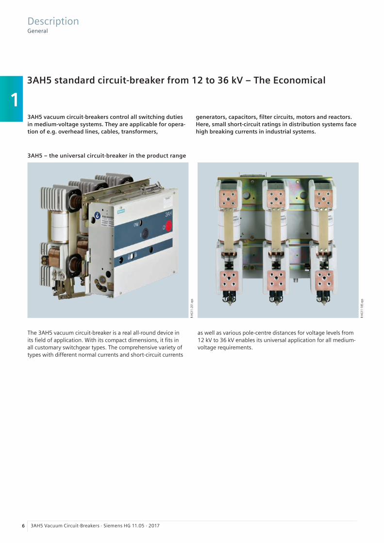
To select the correct spare interrupter, please specify the type designation, serial number and year of manufacture of the circuit-breaker. All data is given on the rating plate.
Vacuum interrupters and other spare parts must only be replaced by instructed personnel.
Note: For any query regarding spare parts, subsequent deliveries, etc. the following three details are necessary: – Type designation – Serial No. – Year of manufacture
Data on the rating plate
2016
HG11
-258
7c_e
n ep
s
Accessories for the plug connector
Included in the scope of supply of the basic equipment for 3AH5 vacuum circuit-breakers:
For 24-pole plug connector
– Lower part of plug – Crimp sockets according to number of contacts – Upper part of plug with screwed contacts
(no crimp sockets required)
For 64-pole plug connector
– Lower part of plug – Upper part of plug – Crimp sockets according to number of contacts
Equipment SelectionAccessories and spare parts
Designation Remarks Operating voltage Order No.
Hand crank Short design 3AX15 30-4A
for charging Standard design 3AX15 30-4B
the closing spring Long design 3AX15 30-4C
Bit for battery screwdriver 3AX15 30-3D
Wire bundle With 10 wires for connection of auxiliary switch to
– 64-pole plug connector 3AX11 34-2D
– 24-pole plug connector 3AX11 34-2B
– 24-pole terminal strip 3AX11 34-2C
64-pole plug connector Upper part of plug incl. sockets 3AX11 34-5A
Lower part of plug incl. pins 3AX11 34-5B
Complete plug connector 3AX11 34-6A
24-pole plug connector Upper part of plug incl. socket insert 3AX11 34-5C
Lower part of plug incl. pins 3AX11 34-5D
Complete plug connector 3AX11 34-7A
Accessories for plug connector (for wire cross-section 1.5 mm2)
Crimp pins for lower part of plug 24-pole 3AX11 34-3A
64-pole 3AX11 34-4B
Crimp sockets for upper part of plug 64-pole 3AX11 34-4C
Crimping pliers 3AX11 34-4D
Disassembly tool 3AX11 34-4G
Accessories

22 3AH5 Vacuum Circuit-Breakers · Siemens HG 11.05 · 2017
R-HG
11-2
01.e
ps

3
233AH5 Vacuum Circuit-Breakers · Siemens HG 11.05 · 2017
Technical Data 23 Electrical data, dimensions, weights and dimension drawings
Voltage level 12 kV 24
Voltage level 17.5 kV 26
Voltage level 24 kV 28
Voltage level 36 kV 30
Operating times, short-circuit protection of motors, consumption data of releases 31
Circuit diagrams 32
Contents Page
R-HG
11-2
02.e
psR-
HG11
-203
.tif
Motor operating mechanism with energy store and closing solenoid
Upper pole support with conductor bar connection
Technical DataContents

3
24 3AH5 Vacuum Circuit-Breakers · Siemens HG 11.05 · 2017
12 kV50 / 60 Hz
Ra
ted
no
rma
l cu
rre
nt
Pole
-ce
ntr
e d
ista
nce
Rate
d o
per
atin
g s
equ
ence
:
O –
3 m
in –
CO
– 3
min
– C
O
O –
0.3
s –
CO
– 3
min
– C
O
O –
0.3
s –
CO
– 1
5 s
– C
O
Rate
d d
ura
tio
n o
f sh
ort
-cir
cuit
Rate
d s
ho
rt-c
ircu
it b
reak
ing
cu
rren
t
DC
co
mp
on
ent
in %
of
the
rate
d s
ho
rt-c
ircu
it b
reak
ing
cu
rren
t
Asy
mm
etri
cal b
reak
ing
cu
rren
t
Rate
d s
ho
rt-c
ircu
it m
akin
g c
urr
ent
(at
50
/60
Hz)
Rate
d b
ack-
to-b
ack
cap
acit
or
ban
km
akin
g c
urr
ent
Rate
d li
gh
tnin
g im
pu
lse
wit
hst
and
vo
ltag
e
Rate
d s
ho
rt-d
ura
tio
n p
ow
er-f
req
uen
cyw
ith
stan
d v
olt
age
Vo
ltag
e d
rop
∆U
bet
wee
n c
on
nec
tio
ns
(acc
ord
ing
to
IEC
62
27
1-1
at
DC
10
0 A
)
Min
imu
m c
reep
age
dis
tan
ce,
in
terr
up
ter
Min
imu
m c
reep
age
dis
tan
ce,
p
has
e-to
-ear
th
Min
imu
m c
lear
ance
,
ph
ase-
to-p
has
e
Min
imu
m c
lear
ance
,
ph
ase-
to-e
arth
Wei
gh
ts
Det
aile
d d
imen
sio
n d
raw
ing
(can
be
ord
ered
)
Op
erat
ing
cyc
le d
iag
ram
no
. (s
ee p
age
25
)
Cat
alo
g d
imen
sio
n d
raw
ing
no
. (s
ee p
age
25
)
Ord
er
No
.
Ir tk Isc Ima Ibi Up Ud
A mm s kA % kA kA
kA Peak
kV kV mV mm mm mm mm kg
3AH5 121-1... 800 160 n 3 13.1 36 14.733/ 34
– *) 75 28 6.0 90 135 88 95 35 S_ 441 00641 1 1.1
3AH5 122-1... 800 160 n 3 16 36 17.940/ 42
10 75 28 3.4 120 135 71 95 40 S_ 441 00643 2 1.3
3AH5 122-2... 1250 160 n 3 16 36 17.940/ 42
10 75 28 3.4 120 135 71 95 40 S_ 441 00643 2 1.3
3AH5 123-1... 800 160 n 3 20 36 22.450/ 52
10 75 28 3.4 120 135 71 95 40 S_ 441 00643 3 1.3
3AH5 123-2... 1250 160 n 3 20 36 22.450/ 52
10 75 28 3.4 120 135 71 95 40 S_ 441 00643 3 1.3
3AH5 125-2... 1250 160 n 3 31.5 36 35.480/ 82
20 75 28 3.0 129 135 60 95 40 S_ 441 00651 5 1.5
3AH5 131-1... 800 210 n 3 13.1 36 14.733/ 34
– *) 75 28 6.0 90 135 138 95 35 S_ 441 00642 1 1.2
3AH5 132-1... 800 210 n 3 16 36 17.940/ 42
10 75 28 3.4 120 135 121 95 40 S_ 441 00644 2 1.4
3AH5 132-2... 1250 210 n 3 16 36 17.940/ 42
10 75 28 3.4 120 135 121 95 40 S_ 441 00644 2 1.4
3AH5 133-1... 800 210 n 3 20 36 22.450/ 52
10 75 28 3.4 120 135 121 95 40 S_ 441 00644 3 1.4
3AH5 133-2... 1250 210 n 3 20 36 22.450/ 52
10 75 28 3.4 120 135 121 95 40 S_ 441 00644 3 1.4
3AH5 133-4... 2000 210 n 3 20 36 22.450/ 52
20 75 28 1.8 129 135 91 95 55 S_ 441 00646 3 1.6
3AH5 134-4... 2000 210 n 3 25 36 2863/ 65
20 75 28 1.8 129 135 91 95 55 S_ 441 00646 4 1.6
3AH5 134-6... 2500 210 n 3 25 36 2863/ 65
20 75 28 1.8 129 135 91 95 55 S_ 441 00646 4 1.6
3AH5 135-2... 1250 210 n 3 31.5 36 35.480/ 82
20 75 28 3.0 129 135 110 95 45 S_ 441 00645 5 1.6
3AH5 135-4... 2000 210 n 3 31.5 36 35.480/ 82
20 75 28 1.8 129 135 91 95 55 S_ 441 00646 5 1.7
3AH5 135-6... 2500 210 n 3 31.5 36 35.480/ 82
20 75 28 1.8 129 135 91 95 55 S_ 441 00646 5 1.6
3AH5 144-1... 800 160 n 3 25 36 2863/ 65
– *) 75 28 3.8 90 135 75 95 40 S_ 441 01301 4 1.8
3AH5 144-2... 1250 160 n 3 25 36 2863/ 65
– *) 75 28 3.8 90 135 75 95 40 S_ 441 01301 4 1.8
3AH5 154-1... 800 210 n 3 25 36 2863/ 65
– *) 75 28 3.8 90 135 125 95 45 S_ 441 01302 4 1.9
3AH5 154-2... 1250 210 n 3 25 36 2863/ 65
– *) 75 28 3.8 90 135 125 95 45 S_ 441 01302 4 1.9
n Standard information on the rating plate Possible with order number suffix Z and order code F27, or standard for manual operating mechanism (14th position A or X) Possible with order number suffix Z and order code F28
*) Not available for this application
Technical DataElectrical data, dimensions, weights and dimension drawings

3
253AH5 Vacuum Circuit-Breakers · Siemens HG 11.05 · 2017
Operating cycle diagrams for 12 kV
Dimension drawing for 12 kV
Value in brackets for 2500 A
Technical DataElectrical data, dimensions, weights and dimension drawings
Dimensiondrawing
a mm
b mm
c mm
d mm
1.1 160 432 490 392
1.2 210 534 592 492
1.3 160 432 490 409
1.4 210 534 592 509
1.5 160 432 490 422
1.6 210 534 592 539
1.7 210 534 592 522
1.8 160 432 490 405
1.9 210 534 592 505
a = Pole-centre distance
b = Width of cross member
c = Width of cross member incl. lugs
d = Largest energized width
The permissible number of
electrical operating cycles
is shown as a function
of the breaking current
(r.m.s. value). All vacuum
circuit-breakers fulfil the
endurance classes E2,
M2 and C2 according
to IEC 62271-100. The
curve shape beyond the
parameters defined in
IEC 62271-100 is based on
average experience data.
The number of operating
cycles that can actually be
reached can be different
depending on the respective
application.

3
26 3AH5 Vacuum Circuit-Breakers · Siemens HG 11.05 · 2017
17.5 kV50 / 60 Hz
Ra
ted
no
rma
l cu
rre
nt
Pole
-ce
ntr
e d
ista
nce
Rate
d o
per
atin
g s
equ
ence
:
O –
3 m
in –
CO
– 3
min
– C
O
O –
0.3
s –
CO
– 3
min
– C
O
O –
0.3
s –
CO
– 1
5 s
– C
O
Rate
d d
ura
tio
n o
f sh
ort
-cir
cuit
Rate
d s
ho
rt-c
ircu
it b
reak
ing
cu
rren
t
DC
co
mp
on
ent
in %
of
the
rate
d s
ho
rt-c
ircu
it b
reak
ing
cu
rren
t
Asy
mm
etri
cal b
reak
ing
cu
rren
t
Rate
d s
ho
rt-c
ircu
it m
akin
g c
urr
ent
(at
50
/60
Hz)
Rate
d b
ack-
to-b
ack
cap
acit
or
ban
km
akin
g c
urr
ent
Rate
d li
gh
tnin
g im
pu
lse
wit
hst
and
vo
ltag
e
Rate
d s
ho
rt-d
ura
tio
n p
ow
er-f
req
uen
cyw
ith
stan
d v
olt
age
Vo
ltag
e d
rop
∆U
bet
wee
n c
on
nec
tio
ns
(acc
ord
ing
to
IEC
62
27
1-1
at
DC
10
0 A
)
Min
imu
m c
reep
age
dis
tan
ce,
in
terr
up
ter
Min
imu
m c
reep
age
dis
tan
ce,
p
has
e-to
-ear
th
Min
imu
m c
lear
ance
,
ph
ase-
to-p
has
e
Min
imu
m c
lear
ance
,
ph
ase-
to-e
arth
Wei
gh
ts
Det
aile
d d
imen
sio
n d
raw
ing
(can
be
ord
ered
)
Op
erat
ing
cyc
le d
iag
ram
no
. (s
ee p
age
27
)
Cat
alo
g d
imen
sio
n d
raw
ing
no
. (s
ee p
age
27
)
Ord
er
No
.
Ir tk Isc Ima Ibi Up Ud
A mm s kA % kA kA
kA Peak
kV kV mV mm mm mm mm kg
3AH5 204-1... 800 160 n 3 25 36 2863/ 65
20 95 38 3.4 129 170 176 130 40 S_ 441 00705 6 2.1
3AH5 204-2... 1250 160 n 3 25 36 2863/ 65
20 95 38 3.4 129 170 176 130 40 S_ 441 00705 6 2.1
3AH5 205-2... 1250 160 n 3 31.5 36 35.480/ 82
20 95 38 2.7 129 170 140 130 40 S_ 441 00652 7 2.1
3AH5 214-1... 800 210 n 3 25 36 2863/ 65
20 95 38 3.4 129 170 108 130 45 S_ 441 00706 6 2.2
3AH5 214-2... 1250 210 n 3 25 36 2863/ 65
20 95 38 3.4 129 170 108 130 45 S_ 441 00706 6 2.2
3AH5 214-6... 2500 210 n 3 25 36 2863/ 65
20 95 38 1.6 129 170 163 130 55 S_ 441 00649 6 2.3
3AH5 215-2... 1250 210 n 3 31.5 36 35.480/ 82
20 95 38 2.7 129 170 108 130 45 S_ 441 00648 7 2.2
3AH5 215-4... 2000 210 n 3 31.5 36 35.480/ 82
20 95 38 1.6 129 170 163 130 55 S_ 441 00649 7 2.3
3AH5 215-6... 2500 210 n 3 31.5 36 35.480/ 82
20 95 38 1.6 129 170 163 130 55 S_ 441 00649 7 2.3
n Standard information on the rating plate Possible with order number suffix Z and order code F27, or standard for manual operating mechanism (14th position A or X) Possible with order number suffix Z and order code F28
Technical DataElectrical data, dimensions, weights and dimension drawings

3
273AH5 Vacuum Circuit-Breakers · Siemens HG 11.05 · 2017
Operating cycle diagram for 17.5 kV
Dimension drawing for 17.5 kV
Value in brackets for 2500 A Barrier for pole-centre distance of 160 mm
a = Pole-centre distance
b = Width of cross member
c = Width of cross member incl. lugs
d = Largest energized width
Dimensiondrawing
a mm
b mm
c mm
d mm
2.1 160 432 490 422
2.2 210 534 592 522
2.3 210 534 592 534
Technical DataElectrical data, dimensions, weights and dimension drawings
The permissible number of
electrical operating cycles
is shown as a function
of the breaking current
(r.m.s. value). All vacuum
circuit-breakers fulfil the
endurance classes E2,
M2 and C2 according
to IEC 62271-100. The
curve shape beyond the
parameters defined in
IEC 62271-100 is based on
average experience data.
The number of operating
cycles that can actually be
reached can be different
depending on the respective
application.

3
28 3AH5 Vacuum Circuit-Breakers · Siemens HG 11.05 · 2017
24 kV50 / 60 Hz
Ra
ted
no
rma
l cu
rre
nt
Pole
-ce
ntr
e d
ista
nce
Rate
d o
per
atin
g s
equ
ence
:
O –
3 m
in –
CO
– 3
min
– C
O
O –
0.3
s –
CO
– 3
min
– C
O
O –
0.3
s –
CO
– 1
5 s
– C
O
Rate
d d
ura
tio
n o
f sh
ort
-cir
cuit
Rate
d s
ho
rt-c
ircu
it b
reak
ing
cu
rren
t
DC
co
mp
on
ent
in %
of
the
rate
d s
ho
rt-c
ircu
it b
reak
ing
cu
rren
t
Asy
mm
etri
cal b
reak
ing
cu
rren
t
Rate
d s
ho
rt-c
ircu
it m
akin
g c
urr
ent
(at
50
/60
Hz)
Rate
d b
ack-
to-b
ack
cap
acit
or
ban
km
akin
g c
urr
ent
Rate
d li
gh
tnin
g im
pu
lse
wit
hst
and
vo
ltag
e
Rate
d s
ho
rt-d
ura
tio
n p
ow
er-f
req
uen
cyw
ith
stan
d v
olt
age
Vo
ltag
e d
rop
∆U
bet
wee
n c
on
nec
tio
ns
(acc
ord
ing
to
IEC
62
27
1-1
at
DC
10
0 A
)
Min
imu
m c
reep
age
dis
tan
ce,
in
terr
up
ter
Min
imu
m c
reep
age
dis
tan
ce,
p
has
e-to
-ear
th
Min
imu
m c
lear
ance
,
ph
ase-
to-p
has
e
Min
imu
m c
lear
ance
,
ph
ase-
to-e
arth
Wei
gh
ts
Det
aile
d d
imen
sio
n d
raw
ing
(can
be
ord
ered
)
Op
erat
ing
cyc
le d
iag
ram
no
. (s
ee p
age
29
)
Cat
alo
g d
imen
sio
n d
raw
ing
no
. (s
ee p
age
29
)
Ord
er
No
.
Ir tk Isc Ima Ibi Up Ud
A mm s kA % kA kA
kA Peak
kV kV mV mm mm mm mm kg
3AH5 272-1... 800 210 n 3 16 36 17.940/ 42
10 125 50 3.8 200 190 215 175 55 S_ 441 00660 8 3.1
3AH5 272-2... 1250 210 n 3 16 36 17.940/ 42
10 125 50 3.8 200 190 215 175 55 S_ 441 00660 8 3.1
3AH5 273-2... 1250 210 n 3 20 36 22.450/ 52
20 125 50 3.8 200 190 215 175 55 S_ 441 00662 9 3.2
3AH5 273-4... 2000 210 n 3 20 36 22.450/ 52
20 125 50 2.2 200 190 227 175 80 S_ 441 00663 9 3.3
3AH5 273-6... 2500 210 n 3 20 36 22.450/ 52
20 125 50 2.2 200 190 227 175 80 S_ 441 00663 9 3.3
3AH5 274-2... 1250 210 n 3 25 36 2863/ 65
20 125 50 3.8 200 190 260 175 55 S_ 441 00662 10 3.2
3AH5 274-6... 2500 210 n 3 25 36 2863/ 65
20 125 50 2.2 200 190 227 175 80 S_ 441 00663 10 3.3
3AH5 282-1... 800 275 n 3 16 36 17.940/ 42
10 125 50 3.8 200 190 180 175 55 S_ 441 00661 8 3.4
3AH5 282-2... 1250 275 n 3 16 36 17.940/ 42
10 125 50 3.8 200 190 180 175 55 S_ 441 00661 8 3.4
3AH5 283-2... 1250 275 n 3 20 36 22.450/ 52
20 125 50 3.8 200 190 165 175 55 S_ 441 00664 9 3.5
3AH5 283-4... 2000 275 n 3 20 36 22.450/ 52
20 125 50 2.2 200 190 135 175 80 S_ 441 00668 9 3.6
3AH5 283-6... 2500 275 n 3 20 36 22.450/ 52
20 125 50 2.2 200 190 135 175 80 S_ 441 00668 9 3.6
3AH5 284-2... 1250 275 n 3 25 36 2863/ 65
20 125 50 3.8 200 190 165 175 55 S_ 441 00664 10 3.5
3AH5 284-6... 2500 275 n 3 25 36 2863/ 65
20 125 50 2.2 200 190 135 175 80 S_ 441 00668 10 3.6
n Standard information on the rating plate Possible with order number suffix Z and order code F27, or standard for manual operating mechanism (14th position A or X) Possible with order number suffix Z and order code F28
Technical DataElectrical data, dimensions, weights and dimension drawings

3
293AH5 Vacuum Circuit-Breakers · Siemens HG 11.05 · 2017
Operating cycle diagram for 24 kV
Dimension drawing for 24 kV
Dimensiondrawing
a mm
b mm
c mm
d mm
3.1 210 534 592 516
3.2 210 534 592 530
3.3 210 534 592 541
3.4 275 650 708 645
3.5 275 650 708 660
3.6 275 650 708 690
Value in brackets for 2500 A Barrier for pole-centre distance of 160 mm
a = Pole-centre distance
b = Width of cross member
c = Width of cross member incl. lugs
d = Largest energized width
Technical DataElectrical data, dimensions, weights and dimension drawings
The permissible number of
electrical operating cycles
is shown as a function
of the breaking current
(r.m.s. value). All vacuum
circuit-breakers fulfil the
endurance classes E2,
M2 and C2 according
to IEC 62271-100. The
curve shape beyond the
parameters defined in
IEC 62271-100 is based on
average experience data.
The number of operating
cycles that can actually be
reached can be different
depending on the respective
application.

3
30 3AH5 Vacuum Circuit-Breakers · Siemens HG 11.05 · 2017
36 kV50 / 60 Hz
Ra
ted
no
rma
l cu
rre
nt
Pole
-ce
ntr
e d
ista
nce
Rate
d o
per
atin
g s
equ
ence
:
O –
3 m
in –
CO
– 3
min
– C
O
O –
0.3
s –
CO
– 3
min
– C
O
O –
0.3
s –
CO
– 1
5 s
– C
O
Rate
d d
ura
tio
n o
f sh
ort
-cir
cuit
Rate
d s
ho
rt-c
ircu
it b
reak
ing
cu
rren
t
DC
co
mp
on
ent
in %
of
the
rate
d s
ho
rt-c
ircu
it b
reak
ing
cu
rren
t
Asy
mm
etri
cal b
reak
ing
cu
rren
t
Rate
d s
ho
rt-c
ircu
it m
akin
g c
urr
ent
(at
50
/60
Hz)
Rate
d b
ack-
to-b
ack
cap
acit
or
ban
km
akin
g c
urr
ent
Rate
d li
gh
tnin
g im
pu
lse
wit
hst
and
vo
ltag
e
Rate
d s
ho
rt-d
ura
tio
n p
ow
er-f
req
uen
cyw
ith
stan
d v
olt
age
Vo
ltag
e d
rop
∆U
bet
wee
n c
on
nec
tio
ns
(acc
ord
ing
to
IEC
62
27
1-1
at
DC
10
0 A
)
Min
imu
m c
reep
age
dis
tan
ce,
in
terr
up
ter
Min
imu
m c
reep
age
dis
tan
ce,
p
has
e-to
-ear
th
Min
imu
m c
lear
ance
,
ph
ase-
to-p
has
e
Min
imu
m c
lear
ance
,
ph
ase-
to-e
arth
Wei
gh
ts
Det
aile
d d
imen
sio
n d
raw
ing
(can
be
ord
ered
)
Op
erat
ing
cyc
le d
iag
ram
no
. (s
ee b
elo
w)
Cat
alo
g d
imen
sio
n d
raw
ing
no
. (s
ee b
elo
w)
Ord
er
No
.
Ir tk Isc Ima Ibi Up Ud
A mm s kA % kA kA
kA Peak
kV kV mV mm mm mm mm kg
3AH5 312-2... 1250 350 n 3 16 36 2840/ 42
20 170 70 3.0 240 310 256 300 85 S_ 441 00910 11 4.2
3AH5 314-2... 1250 350 n 3 25 36 2863/ 65
20 170 70 3.0 240 310 256 300 85 S_ 441 00910 12 4.2
3AH5 314-4... 2000 350 n 3 25 36 2863/ 65
20 170 70 2.5 240 310 256 300 110 S_ 441 00676 12 4.2
3AH5 322-2... 1250 275 n 3 16 36 2840/ 42
20 170 70 3.0 240 310 256 300 75 S_ 441 00990 11 4.1
3AH5 324-2... 1250 275 n 3 25 36 2863/ 65
20 170 70 3.2 240 310 256 300 75 S_ 441 00990 12 4.1
n Standard information on the rating plate Possible with order number suffix Z and order code F27, or standard for manual operating mechanism (14th position A or X) Possible with order number suffix Z and order code F28
Operating cycle diagram and dimension drawing for 36 kV
The permissible number of electrical operating cycles
is shown as a function of the breaking current (r.m.s. value).
All vacuum circuit-breakers fulfil the endurance classes E2,
M2 and C2 according to IEC 62271-100. The curve shape
beyond the parameters defined in IEC 62271-100 is based on
average experience data. The number of operating cycles that
can actually be reached can be different depending on the
respective application.
Dimensiondrawing
a mm
b mm
c mm
d mm
4.1 275 650 708 668
4.2 350 810 868 818
Value in brackets for 2000 A
a = Pole-centre distance
b = Width of cross member
c = Width of cross member incl. lugs
d = Largest energized width
Technical DataElectrical data, dimensions, weights and dimension drawings

3
313AH5 Vacuum Circuit-Breakers · Siemens HG 11.05 · 2017
Operating times
Operating times at rated voltageof the secondary circuit
Equipment of circuit-breaker Operating time of circuit-breaker
Closing time – < 65 ms 1)
Opening time 1st shunt release < 55 ms 1)
2nd release < 45 ms
Arcing time – < 15 ms
Break time 1st shunt release < 70 ms
2nd release < 60 ms
Dead time – 300 ms
CLOSE /OPEN contact time 1st shunt release < 75 ms
2nd release < 60 ms
Minimum command duration Closing solenoid 45 ms
1st shunt release 40 ms
2nd release 20 ms
Pulse time for circuit-breaker tripping signal 1st shunt release > 15 ms
2nd release > 10 ms
Charging time for electrical operation – < 15 s
Synchronism error between the poles – ≤ 2 ms
1) Shorter operating times on request.
Short-circuit protection of motors (fuse protection of drive motors)
Rated voltageof the motor
Operating voltage
Power consumption of the motor
Smallest possible ratedcurrent 2) of the m.c.b.(miniature circuit-breaker)with C-characteristic
V max. V min. V W (at DC) VA (at AC) A
DC 24 26 20 650 – 10
DC 48 53 41 650 – 8
DC 60 66 51 650 – 6
DC 110 121 93 650 – 4
DC 220 242 187 650 – 3
AC 110 121 93 – 650 3
AC 230 244 187 – 650 2
2) The current inrush in the drive motor can be neglected due to its very short presence.
Consumption data of releases
Release Power consumption Tripping ranges
Operation at Tripping voltage Tripping voltageor tripping current
DC approx. W
AC 50 / 60 Hz approx. VA
at DC
at AC 50 / 60 Hz
Closing solenoid 3AY15 10 140 – 210 140 – 210 85 to 110 % U 85 to 110 % U
1st shunt release (without energy store) 3AY15 10
140 140 70 to 110 % U 85 to 110 % U
2nd shunt release (with energy store) 3AX11 01
70 50 70 to 110 % U 85 to 110 % U
Undervoltage release 3AY11 03 20 20 35 to 0 % U 35 to 0 % U
Current-transformer operated release 3AX11 02 (rated normal current 0.5 A or 1 A)
– 10 3) – 90 to 110 % Ia
Current-transformer operated release 3AX11 04 (tripping pulse ≥ 0.1 Ws)
– – – –
3) Consumption at pickup current (90 % of the rated normal current) and open armature.
Technical DataOperating times, short-circuit protection of motors and consumption data of releases

3
32 3AH5 Vacuum Circuit-Breakers · Siemens HG 11.05 · 2017
Circuit diagrams
The circuit diagrams shown here are examples from the manifold possibilities of circuit-breaker wiring.
The available possible combinations are described in the chapter “Selection of secondary equipment”.
Motor charging for DC Motor charging withrectifier for AC
Closing and anti-pumping
Signal: Spring charged with 24-pole plug connector
Circuit-breaker tripping for 24 /64-pole plug connector
1st shunt release (2nd shunt release) with 64-pole plug connector
1st shunt release (2nd shunt release) with 24-pole plug connector
1st current- transformer operated release
Low-energy current-transformer operated release
Undervoltage release
HA Manual openingHE Manual closingK1 Contactor (anti-pumping)M1 Motor operating mechanismP Energy storeR1 Resistance
Legend
Technical DataCircuit diagrams
1) Internally wired
2) Not wired
3) Integrated varistor for ≥ 60 V DC
4) Integrated varistor for ≥ 100 V AC /DC
5) Additional rectifier only required for AC
6) Only in connection with mechanical interlocking
S1 Auxiliary switchS3 Position switch (opens when
closing spring is charged)S4 Position switch (indicates the charging state)S6 Circuit-breaker tripping signalS7 Cutout switch for circuit-breaker
tripping signal
S12 Mechanical interlockingS21, Position switchesS22 (to de-energize the motor operating
mechanism after charging)V6 RectifierX0 Lower part of plugY1 1st shunt release
Y2 2nd shunt releaseY4 Current-transformer
operated releaseY6 Low-energy current-
transformer operated release
Y7 Undervoltage releaseY9 Closing solenoid
Motor operating stored-energy mechanism

4
333AH5 Vacuum Circuit-Breakers · Siemens HG 11.05 · 2017
Annex 33 Inquiry form 34
Configuration instructions 35
Configuration aid Foldout page
Contents Page
R-HG
11-1
81.e
ps
Brandenburg Gate, Berlin, Germany
R-HG
11-1
80.e
ps
Switchgear Factory, Berlin, Germany
AnnexContents

4
34 3AH5 Vacuum Circuit-Breakers · Siemens HG 11.05 · 2017
Inquiry concerning
£ 3AH5 circuit-breaker
Please
£ Submit an offer£ Call us£ Visit us
Your address
Company
Dept.
Name
Street
Postal code /city
Country
Phone
Fax
Siemens AG
Dept.
Name
Street
Postal code /city
Country
Fax
Technical data Other values
Rated voltage £ 12 kV £ 17.5 kV £ 24 kV £ 36 kV £ ___ kV
Rated lightning impulse £ 75 kV £ 95 kV withstand voltage £ 125 kV £ 170 kV £ ___ kV
Rated short-duration £ 28 kV £ 38 kV £ 42 kV power-frequency withstand voltage £ 50 kV £ 70 kV £ ___ kV
Rated short-circuit £ 13.1 kA £ 16 kA £ 20 kA breaking current £ 25 kA £ 31.5 kA £ ___ kA
Rated normal current £ 800 A £ 1250 A £ 2000 A £ 2500 A £ ___ A
Pole-centre distance £ 160 mm £ 210 mm £ 275 mm £ 350 mm
Secondary equipmentFor possible combinations see pages 15 to 19
Circuit-breaker equipment £ Manual spring-operated mechanism £ Manual operating stored-energy mechanism £ Motor operating stored-energy mechanism
Motor operating mechanism £ ___ V DC £ ___ V AC, ___ Hz
Closing solenoid £ ___ V DC £ ___ V AC, ___ Hz
1 shunt release £ ___ V DC £ ___ V AC, ___ Hz
2 shunt release £ ___ V DC £ ___ V AC, ___ Hz
Current-transformer operated release £ 0.5 A £ 1 A £ ≥ 0.1 Ws 10 Ω £ ≥ 0.1 Ws 20 Ω
Undervoltage release £ ___ V DC £ ___ V AC, ___ Hz
Auxiliary switch £ 2 NO + 2 NC £ 6 NO + 6 NC £ 12 NO + 12 NC
Low-voltage connection £ without £ 24-pole £ 24-pole £ 64-pole terminal strip plug plug
£ Mechanical interlocking
£ Counter
£ Circuit-breaker tripping signal
£ Electrical closing lock-out
Operating instructions £ English £ German £ French £ Spanish
Application and other requirements
£ Please check off ___ Please fill in
Please copy, fill in and return to your Siemens partner.
AnnexInquiry form
st
nd

353AH5 Vacuum Circuit-Breakers · Siemens HG 11.05 · 2017
Instruction for configuration of the 3AH5 vacuum circuit-breaker
1st step: Definition of the primary part (see page 13 to 14)
Please specify the following ratings: Possible options:
Rated voltage (Ur) Ur: 12 kV, 17.5 kV, 24 kV, 36 kV
Rated lightning impulse withstand voltage (Up) Up: 75 kV, 95 kV, 125 kV, 170 kV
Rated short-duration power-frequency withstand voltage (Ud) Ud: 28 kV, 38 kV, 42 kV, 50 kV, 70 kV
Rated short-circuit breaking current (Isc) Isc: 13.1 kA, 16 kA, 20 kA, 25 kA, 31.5 kA
Rated normal current (Ir) 160 mm, 210 mm, 275 mm, 350 mm
Pole-centre distance Ir: 800 A, 1250 A, 2000 A, 2500 A
These ratings define the positions 5 to 8 of the order number.
2nd step: Definition of the secondary equipment (see pages 15 to 19)
Please specify the following equipment features: Possible options:
Release combination(position 9)
Shunt release, current-transformer operated releaseand undervoltage release
Closing solenoid(position 10)
Operating voltages from 24 V DC to 240 V AC
Operating voltage of the releases(positions 11 /12)
Operating voltages from 24 V DC to 240 V AC
Equipment with circuit-breaker tripping signal(position 13)
Equipment depends on the selection of thesecondary connection
Type of operating mechanism and operating voltage of a motor, if available(position 14)
Manual spring-operated mechanism,manual operating stored-energy mechanism,motor operating stored-energy mechanismwith operating voltages from 24 V DC to 240 V AC
Number of auxiliary contacts(position 15)
2 NO + 2 NC, 6 NO + 6 NC, 12 NO + 12 NC
Design of the secondary connection(position 15)
24-pole terminal strip, 24-pole plug connector,64-pole plug connector, without plug connector
Language of the documentation(position 16)
English, German, French, Spanish, other languages on request
Frequency of the operating voltage of thesecondary equipment at AC (position 16)
50 Hz /60 Hz
These equipment features define the positions 9 to 16 of the order number.
3rd step: Do you have any further requirements concerning the equipment? (see page 20)
Your Siemens sales partner will be pleased to support you.
You prefer to configure your 3AH5 vacuum circuit-breaker on your own?Follow the steps to the configuration and enter the order number in the configuration aid.

1 2 3 4 5 6 7 – 8 9 10 11 12 – 13 14 15 16
3 A H 5 n n n – n n n n n – n n n n – Z
See
pag
e 1
3
and
pag
e 1
4
See
pag
e 1
5
See
pag
e 1
6
See
pag
e 1
6
See
pag
e 1
7
See
pag
e 1
8
See
pag
e 1
8
See
pag
e 1
9
See
pag
e 1
9
See
pag
e 2
0
3 A H 5 – –
+ + + +
+ + + +
3 A H 5 – –
+ + + +
+ + + +
3 A H 5 – –
+ + + +
+ + + +
3 A H 5 – –
+ + + +
+ + + +
3 A H 5 – –
+ + + +
+ + + +
3 A H 5 – –
+ + + +
+ + + +
3 A H 5 – –
+ + + +
+ + + +
3 A H 5 – –
+ + + +
+ + + +
For configuration of your 3AH5 vacuum circuit-breaker


2017
Published by Siemens AG 2017 Energy Management Division Medium Voltage & Systems Nonnendammallee 104 13623 Berlin, Germany
For further information please contact our Customer Support Center Phone: +49 180 524 70 00 Fax: +49 180 524 24 71 E-mail: [email protected]
Article No. EMMS-K1511-A051-A3-7600 Printed in Germany Dispo 18301 PU 184/1406 KG 03.17 0.25
Subject to changes and errors. The information given in this document only contains general descriptions and /or performance features which may not always specifically reflect those described, or which may undergo modification in the course of further development of the products. The requested performance features are binding only when they are expressly agreed upon in the con-cluded contract.