Embed Size (px)
Citation preview

Catalog
HG 11.06 ·
Edition 2017
siemens.com/medium-voltage-components
3AK7 Vacuum Circuit-Breakers Medium-Voltage Equipment

2 3AK7 Vacuum Circuit-Breakers · Siemens HG 11.06 · 2017
R-HG
11-3
73.ti
f

1
2
3
4
33AK7 Vacuum Circuit-Breakers · Siemens HG 11.06 · 2017
Description 5General 6
Construction and mode of operation 7
Standards, maintenance-free design 8
Ambient conditions and operating conditions 9
Technical data and basic equipment 10
Equipment Selection 11Order number structure 12
Selection of basic types, circuit-breakers 13
Selection of secondary equipment 15
Selection of additional equipment 20
Accessories and spare parts 21
Technical Data 25Electrical data, dimensions and masses 26
Dimension drawings 28
Circuit diagrams 32
Operating times, short-circuit protection of motors 34
Consumption data of releases 35
Annex 37Inquiry form 38
Configuration instructions 39
Configuration aid Foldout page
Contents Page
3AK7 Vacuum Circuit-Breakers Medium-Voltage Equipment
Catalog HG 11.06 · 2017
Invalid: Katalog HG 11.06 · 2014
Contents
The products and systems described in this catalog are manufactured and sold according to a certified management system (acc. to ISO 9001, ISO 14001 and BS OHSAS 18001).

4 3AK7 Vacuum Circuit-Breakers · Siemens HG 11.06 · 2017
R-HG
11-3
57.ti
f

1
53AK7 Vacuum Circuit-Breakers · Siemens HG 11.06 · 2017
Description 5
General 6
Construction and mode of operation 7
Switching medium 7
Pole assemblies 7
Operating mechanism box 7
Operating mechanism 7
Trip-free mechanism 7
Releases 8
Closing 8
Circuit-breaker tripping signal 8
Interlocks 8
Standards, maintenance-free design 8
Ambient conditions and operating conditions
Ambient conditions 9
Current carrying capacity 9
Dielectric strength 9
Technical data and basic equipment 10
Contents Page
R-HG
11-1
74.ti
f
Industrial application: Refinery
DescriptionContents
1
6 3AK7 Vacuum Circuit-Breakers · Siemens HG 11.06 · 2017
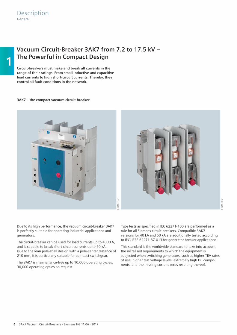
Vacuum Circuit-Breaker 3AK7 from 7.2 to 17.5 kV – The Powerful in Compact Design
3AK7 – the compact vacuum circuit-breaker
Due to its high performance, the vacuum circuit-breaker 3AK7 is perfectly suitable for operating industrial applications and generators.
The circuit-breaker can be used for load currents up to 4000 A, and is capable to break short-circuit currents up to 50 kA. Due to the lean pole-shell design with a pole-center distance of 210 mm, it is particularly suitable for compact switchgear.
The 3AK7 is maintenance-free up to 10,000 operating cycles. 30,000 operating cycles on request.
Circuit-breakers must make and break all currents in the range of their ratings: From small inductive and capacitive load currents to high short-circuit currents. Thereby, they control all fault conditions in the network.
DescriptionGeneral
R-HG
11-3
74.ti
f
Type tests as specified in IEC 62271-100 are performed as a rule for all Siemens circuit-breakers. Compatible 3AK7 versions for 40 kA and 50 kA are additionally tested according to IEC / IEEE 62271-37-013 for generator breaker applications.
This standard is the worldwide standard to take into account the increased requirements to which the equipment is subjected when switching generators, such as higher TRV rates of rise, higher test voltage levels, extremely high DC compo-nents, and the missing current zeros resulting thereof.
R-HG
11-4
00 ti
f

1
73AK7 Vacuum Circuit-Breakers · Siemens HG 11.06 · 2017
5
4
1
3
2
6HG
11-2
881a
eps
7
R-HG
11-3
76.ti
fR-
HG11
-377
.tif
DescriptionDesign and mode of operation
The vacuum circuit-breaker consists of the pole assemblies (1) and the operating mechanism box (2). Each of the three pole assemblies is supported by its pole shell, which is fastened to the pole plate (7). The switching movement is transferred by means of operating rods (6).
Switching medium
The vacuum switching technology, proven and fully developed for more than 40 years, serves as arc-quenching principle by using vacuum interrupters (4).
Pole assemblies
One pole assembly (1) of the 3AK7 vacuum circuit-breaker consists of the upper interrupter support (3), the vacuum in-terrupter (4) and the lower interrupter support (5). These ele-ments are covered by the pole shell. The vacuum interrupter is air-insulated and mounted rigidly to the upper interrupter sup-port (3). The lower part of the vacuum interrupter is guided in the lower interrupter support (5), allowing axial movement.
Operating mechanism box
The whole operating mechanism with releases, auxiliary switches, indicators and actuating devices is accommodated in the operating mechanism box. The extent of the secondary equipment depends on the case of application and offers a multiple variety of options in order to meet almost every re-quirement.
Operating mechanism
The circuit-breaker operating mechanism is a stored-energy mechanism. The closing spring can be charged either electri-cally or manually, and latches automatically in when charging is complete. The closing spring acts as a stored-energy mecha-nism. The force is transmitted from the operating mechanism to the pole assemblies via operating rods. To close the breaker, the closing spring can be unlatched either mechanically at the device (ON pushbutton), or electrically by remote control. The closing spring charges the opening or contact-pressure springs as the breaker closes. The now discharged closing spring will be charged again automatically by the drive motor or by hand. Then the operating sequence OPEN-CLOSE-OPEN is stored in the springs. By means of a position switch, the charging condi-tion of the closing spring can be checked electrically.
Trip-free mechanism
3AK7 vacuum circuit-breakers have a trip-free mechanism according to IEC 62271-100. In the event of an opening com-mand being given after a closing operation has been initiated, the moving contacts return to the open position and remain there even if the closing command is sustained. This means that the contacts are momentarily in the closed position, which is permissible according to IEC 62271-100.
Circuit-breaker structure
1 Pole assembly in pole shell2 Operating mechanism box3 Upper interrupter support4 Vacuum interrupter5 Lower interrupter support6 Operating rod7 Pole plate
Front view
Open operating mechanism box

1
8 3AK7 Vacuum Circuit-Breakers · Siemens HG 11.06 · 2017
DescriptionConstruction and mode of operation, standards, maintenance-free design
It remains in this position until a new CLOSE command is given. In this manner, continuous closing and opening (“pumping“) is prevented.
Circuit-breaker tripping signal
During the opening operation of the vacuum circuit-breakers, a NO contact makes brief contact. This is often used to operate a hazard warning system which should only respond in case of automatic tripping of the circuit-breaker. Therefore, contact-ing of the NO contact must be interrupted in case of deliberate opening. In case of local operation, this is done via a cutout switch connected in series with the NO contact.
Interlocks
Electrical interlockingAs the local manual operation of the circuit-breaker can also implemented electrically, the 3AK7 can be perfectly integrated in switchgear interlocks.
The electrical interlocking of disconnectors or earthing switch-es on the switchgear side can be implemented by means of magnetic lockout mechanisms, which are activated via the auxiliary switch of the 3AK7.
On the other hand, the circuit-breaker is activated by the dis-connector or its operating mechanism in such a way that it can only be closed in the end positions of the disconnector. To do this, the circuit-breaker operating mechanism must be equipped with the manual electrical closing system.
Mechanical interlockingTo interlock circuit-breaker trucks, withdrawable parts or disconnectors according to the switch position, the circuit-breakers can be equipped with a mechanical interlocking. A sensor at the switchgear checks the position of the circuit-breaker and prevents the open circuit-breaker in a reliable way from being closed mechanically and electrically.
Standards
The 3AK7 vacuum circuit-breakers conform to the following standards:
• IEC 62271-100• IEC 62271-1• IEC 60265-1 and• IEC / IEEE 62271-37-013:2015 (marked accordingly).
All 3AK7 vacuum circuit-breakers fulfill the endurance classes E2, M2, S1 and C2 according to IEC 62271-100.
Maintenance-free design
The 3AK7 vacuum circuit-breakers are maintenance-free:
• Under normal ambient conditions according to IEC 62271-1• Up to 10,000 operating cycles.
Releases
A release is a device which transfers electrical commands from an external source, such as a control room, to the latching mechanism of the vacuum circuit-breaker so that it can be opened or closed. Apart from the closing solenoid, the maxi-mum possible equipment is one shunt release and two other releases. For release combinations, refer to page 16.
• The closing solenoid unlatches the charged closing spring of the vacuum circuit-breaker, closing it by electrical means. It is suitable for AC or DC voltage.
• Shunt releases are used for automatic tripping of vacuum circuit-breakers by suitable protection relays, and for deliberate tripping by electrical means. They are intended for connection to external voltage (DC or AC voltage), but in special cases they can also be connected to a voltage transformer for deliberate operation.
• Current-transformer operated releases comprise a stored-energy mechanism, an unlatching mechanism, and an electromagnetic system. They are used when there is no external source of auxiliary power (e.g. a battery). Tripping is effected by means of a protection relay (e.g. overcur-rent-time protection) acting on the current-transformer operated release. When the tripping current is exceeded (= 90 % of the rated normal current of the current-trans-former operated release), the latch of the energy store and thus, the opening of the vacuum circuit-breaker, is released.
• Undervoltage releases comprise a stored-energy mecha-nism, an unlatching mechanism and an electromagnetic system which is permanently connected to the secondary or auxiliary voltage while the vacuum circuit-breaker is closed. If the voltage falls below a predetermined value, unlatching of the undervoltage release is enabled and the vacuum circuit-breaker is opened via the stored-energy mechanism. The deliberate tripping of the undervoltage release generally takes place via an NC contact in the trip-ping circuit or via an NO contact by short-circuiting the magnet coil. With this type of tripping, the short-circuit current is limited by the built-in resistors. Undervoltage releases can also be connected to voltage transformers. When the operating voltage drops to impermissibly low levels, the circuit-breaker is tripped automatically. For de-layed tripping, the undervoltage release can be combined with energy stores.
Closing
In the standard version, 3AK7 vacuum circuit-breakers can be remote-closed electrically. They can also be closed locally by mechanical unlatching of the closing spring via pushbutton. Instead of this “manual mechanical closing“, a “manual electri-cal closing“ is also available. In this version, the closing circuit of the circuit-breaker is controlled electrically via a momentary contact instead of the pushbutton. Thus, switchgear-related in-terlocks can also be considered during local closing operations, and unintentional closing can be prevented. If constant CLOSE and OPEN commands are present at the vacuum circuit-breaker at the same time, the vacuum circuit-breaker will return to the open position after closing.

1
93AK7 Vacuum Circuit-Breakers · Siemens HG 11.06 · 2017
max. 95% per daymax. 90% per month
HG
11-2
515a
_en
eps
3
2
4
5
2000
3000
1000
0
A
Rate
d n
orm
al c
urr
ent
4000
5000
40302010 50 60 70°C
Ambient air temperature
HG
11
-25
93
e_en
eps
1
2500200015001000 3000 3500 4000m
1.50
1.40
1.30
1.20
1.00
1.10
HG
11-2
870a
_en
eps
Altit
ude
corr
ectio
n fa
ctor
Ka
Site altitude H
DescriptionAmbient conditions, current carrying capacity and dielectric strength
Ambient conditions
The vacuum circuit-breakers are designed for the normal operating conditions defined in IEC 62271-100.
Condensation can occasionally occur under the ambient conditions shown opposite. 3AK7 vacuum circuit-breakers are suitable for use in the following climatic classes according to IEC 60721, Part 3-3:
Climatic ambient conditions: Class 3K4 1) 3K6 2), 3Z2, 3Z5 Biological ambient conditions: Class 3B1 Mechanical ambient conditions: Class 3M2 Chemically-active substances: Class 3C2 3) Mechanically-active substances: Class 3S2 4)
1) Maximum of 24-hour mean: + 35 °C2) Without icing and wind-driven precipitation3) Without appearance of saline fog and simultaneous condensation4) Restriction: Clean insulation parts
Current carrying capacity
The rated normal currents specified in the diagram have been defined according to IEC 62271-100 for an ambient air temperature of + 40 °C and apply to open switchgear. For enclosed switchgear the data of the switchgear manufacturer applies. At ambient air temperatures below + 40 °C, higher normal currents can be carried (see diagram).
Characteristics curve 1 = Rated normal current 1250 A Characteristics curve 2 = Rated normal current 2000 A Characteristics curve 3 = Rated normal current 2500 A Characteristics curve 4 = Rated normal current 3150 A Characteristics curve 5 = Rated normal current 4000 A
Dielectric strength
The dielectric strength of air insulation decreases with increas-ing altitude due to low air density. According to IEC 62271-1, the values of the rated lightning impulse withstand voltage and the rated short-duration power-frequency withstand voltage specified in the chapter “Technical Data“ apply to a site altitude of 1000 m above sea level. For an altitude above 1000 m, the insulation level must be corrected according to the opposite diagram.
The characteristic shown applies to both rated withstand voltages.
To select the devices, the following applies:
U ≥ U0 × Ka
U Rated withstand voltage under reference atmosphereU0 Rated withstand voltage requested for the place of installationKa Altitude correction factor according to the opposite diagram
Example
For a requested rated lightning impulse withstand voltage of 75 kV at an altitude of 2500 m, an insulation level of 90 kV under reference atmosphere is required as a minimum:
90 kV ≥ 75 kV × 1.2

1
10 3AK7 Vacuum Circuit-Breakers · Siemens HG 11.06 · 2017
Technical data
Standard circuit-breaker (IEC 62271-100)
Generator circuit-breaker (IEC / IEEE 62271-37-013:2015)
Rated voltage Ur (kV) 7.2 12 17.5 7.2 12 15 *17.5
Rated normal current Ir A 1250; 2000; 2500; 3150; 4000 (with forced cooling)
Rated lightning impulse withstand voltage UP kV 60 75 95 60 60 75 75 95 * 95 *
Rated short-duration power-frequency withstand voltage Ud
kV 20 28 38 20 20 28 28 38 * 38 *
Rated short-circuit breaking current Isc kA 50 40 50 40 50 40 50
Pole-center distance mm 210/280
* For generator switching applications: Ud and Up fulfill the specification with rated voltage 15 kV acc. to IEC / IEEE 62271-37-013:2015 and 17.5 kV acc. to IEC 62271-100
DescriptionTechnical data and basic equipment
For the endurance class C2, all circuit-breakers fulfill the following values according to IEC 62271-100
Line Cable Single capacitor bank Back-to-back capacitor bank 1)
Rated voltage Rated line-charging breaking current
Rated cable-charging breaking current
Rated single capacitor bank breaking current 2)
Rated back-to-back capacitor bank breaking
current
Frequency of the inrush current
Ur kV, r.m.s.
Il A, r.m.s.
Ic A, r.m.s.
Isb A, r.m.s.
Ibb A, r.m.s.
fbl Hz
7.2 10 10 400 400 425012 10 25 400 400 425015 10 25 400 400 4250
17.5 10 31.5 400 400 4250
1) Rated back-to-back capacitor bank making current for a back-to-back capacitor bank – see chapter 3: Technical data2) The capacitive switching capacity of the circuit-breaker is 0.7 × Ir above the standard specification
Basic equipment
Equipment Minimum equipment Alternative equipment Remark
Operating mechanism Electrical operating mechanism (hand crank not included in the scope of supply)
Manual operating mechanism (hand crank included in scope of supply)
Hand crank available as accessory
Closing Closing solenoid and manual mechanical closing
Manual electrical closing –
1st release Shunt release None –
2nd release Without Shunt release, undervoltage release, c.t.-operated release
Max. 3 releases can be combined (for possible release combinations, see page 16)
3rd release Without Shunt release, undervoltage release, c.t.-operated release
Max. 3 releases can be combined (for possible release combinations, see page 16)
Varistor circuit Generally installed for ≥ 60 V DC None For limiting switching over- voltages by inductive consumers
Auxiliary switch 6 NO + 6 NC 12 NO + 12 NC –
Plug connection 24-pole terminal strip 24-pole plug, 64-pole plug –
Anti-pumping Available None –
Circuit-breaker tripping signal
Available None –
Operations counter Available None –
“Spring charged“ signal and indication
Available None –
Interlocking Without Mechanical interlocking –

2
113AK7 Vacuum Circuit-Breakers · Siemens HG 11.06 · 2017
Equipment Selection 11 Order number structure 12
Selection of basic types, circuit-breakers
Voltage level 7.2 kV to 17.5 kV 13
Selection of secondary equipment
Operating voltage of the operating mechanism 15
Release combination 16
Operating voltage of the closing solenoid 17
Operating voltage of the 1st shunt release 17
Operating voltage of the 2nd release 18
Operating voltage of the 3rd release 18
Circuit-breaker installation equipment/ circuit-breaker design 18
Auxiliary switch, secondary connection, interlocking 19
Languages of operating instructions and rating plate, as well as AC frequency of operating voltage 19
Selection of additional equipment 20
Accessories and spare parts 21
Rating plate 21
Accessories catalog 22
Contents Page
R-HG
11-3
78.ti
fR-
HG11
-379
.tif
3AK7 vacuum circuit-breaker (4000 A)
3AK763 generator circuit-breaker
Equipment SelectionContents

2
12 3AK7 Vacuum Circuit-Breakers · Siemens HG 11.06 · 2017
Equipment SelectionOrder number structure
Order number structure
The vacuum circuit-breakers consist of a primary and a secondary part. The relevant data make up the 16-digit order number. The primary part covers the main electrical data of the circuit-breaker poles. The secondary part covers all auxiliary devices which are necessary for operating and controlling the vacuum circuit-breaker.
Order codes
Individual equipment versions, marked with “9” or “Z” in the 9th to 16th position, are explained more in detail by a 3-digit order code. Several order codes can be added to the order number in succession and in any sequence.
Special versions («)
For special versions, “-Z“ is added to the order number and a descriptive order code follows. If several built-on components and special versions are required, the suffix “-Z“ is listed only once. If a requested special version is not in the catalog and can therefore not be ordered via order code, it has to be iden-tified with Y 9 9 after consultation. The agreement hereto is made directly between your responsible sales partner and the order processing department in the Switchgear Factory Berlin.
a: alphabetical n: numerical
Position: 1 2 3 4 5 6 7 – 8 9 10 11 12 – 13 14 15 16 Order codes
Order No.: 3 A K n n n n – n a a n n – n a a n – « n n n
Primary part1st position Superior group
Switching devices
2nd position Main groupCircuit-breaker
3rd position SubgroupCircuit-breaker type series
4th to 7th position Basic equipmentDesign and ratings of primary part
Secondary part8th to 16th position except 14th position
Secondary equipmentOperating mechanism, releases and further auxiliary equipment
14th position Circuit-breaker design
Order codesGroups of 3 after the Order No. Format: a n a
Special versions («)Initiated with “Z“Groups of 3 after the Order No. Format: a n n
On the foldout page we offer a configuring aid. Here you can fill in the order number you have determined for your circuit-breaker.
Example for Order No.: 3 A K 7 6 4 2 – n n n n n – n n n n
Order codes:

2
133AK7 Vacuum Circuit-Breakers · Siemens HG 11.06 · 2017
7.2 kV Position: 1 2 3 4 5 6 7 – 8 9 10 11 12 13 14 15 16 Order codes
50/60 Hz Order No.: 3 A K 7 n n n – n n n n n – n n n n – « n n n
Rate
d v
olt
age
Rate
dlig
htn
ing
imp
uls
e
wit
hst
and
vo
ltag
e
Rate
d s
ho
rt-d
ura
tio
n
po
wer
-fre
qu
ency
w
ith
stan
d v
olt
age
Rate
d s
ho
rt-c
ircu
it
bre
akin
g c
urr
ent
at 3
6 %
DC
co
mp
on
ent
Rate
d s
ho
rt-c
ircu
it
mak
ing
cu
rren
t
Pole
-cen
ter
dis
tan
ce
Rate
dn
orm
al c
urr
ent
Ur Up Ud ISC Ima Ir
kV kV kV kA kA mm A
7.2 60 20 50 125/130 210/280 1) 1250 3 A K 7 4 4 2
2000 3 A K 7 4 4 4
2500 3 A K 7 4 4 6
3150 3 A K 7 4 4 7
4000 2) 3 A K 7 4 4 8
Special version Ud = 32 kV – Z E 1 6
12 kV50/60 Hz
Ur Up Ud ISC Ima Ir
kV kV kV kA kA mm A
12 75 28 50 125/130 210/280 1) 1250 3 A K 7 5 4 2
2000 3 A K 7 5 4 4
2500 3 A K 7 5 4 6
3150 3 A K 7 5 4 7
4000 2) 3 A K 7 5 4 8
Special version Ud = 42 kV – Z E 1 3
17.5 kV50/60 Hz
Ur Up Ud ISC Ima Ir
kV kV kV kA kA mm A
17.5 95 38 50 125/130 210/280 1) 1250 3 A K 7 6 4 2
2000 3 A K 7 6 4 4
2500 3 A K 7 6 4 6
3150 3 A K 7 6 4 7
4000 2) 3 A K 7 6 4 8
Special version (available for all 17.5 kV circuit-breakers)
Ud = 42 kV – Z E 1 3
1) The PCD is selected at the 14th position of the order number2) With forced cooling
Equipment SelectionSelection of basic types, circuit-breakers

2
14 3AK7 Vacuum Circuit-Breakers · Siemens HG 11.06 · 2017
7.2 kV generator circuit-breaker acc. to IEC / IEEE 62271-37-013:2015; 50 /60 Hz
1 2 3 4 5 6 7 – 8 9 10 11 12 13 14 15 16 Order codes
3 A K 7 n n n – n n n n n – n n n n – « n n n
Rate
d v
olt
age
Rate
d li
gh
tnin
g im
pu
lse
wit
hst
and
vo
ltag
e
Rate
d s
ho
rt-d
ura
tio
n
po
wer
-fre
qu
ency
w
ith
stan
d v
olt
age
Rate
d s
ho
rt-c
ircu
it
bre
akin
g c
urr
ent
at 3
6 %
DC
co
mp
on
ent
Rate
d s
ho
rt-c
ircu
it
mak
ing
cu
rren
t
Pole
-cen
ter
dis
tan
ce
Rate
d n
orm
al c
urr
ent
Ur Up Ud ISC Ima Ir
kV kV kV kA kA mm A
7.2 60 20 40 110 210/280 1) 1250 3 A K 7 4 3 2
2000 3 A K 7 4 3 4
2500 3 A K 7 4 3 6
3150 3 A K 7 4 3 7
4000 2) 3 A K 7 4 3 8
60 20 50 137 210/280 1) 1250 3 A K 7 4 5 2
2000 3 A K 7 4 5 4
2500 3 A K 7 4 5 6
3150 3 A K 7 4 5 7
4000 2) 3 A K 7 4 5 8
Special version Ud = 32 kV – Z E 1 6
12 kV generator circuit-breakeracc. to IEC / IEEE 62271-37-013:2015; 50 /60 Hz
Ur Up Ud ISC Ima Ir
kV kV kV kA kA mm A
12 75 28 40 110 210/280 1) 1250 3 A K 7 5 3 2
2000 3 A K 7 5 3 4
2500 3 A K 7 5 3 6
3150 3 A K 7 5 3 7
4000 2) 3 A K 7 5 3 8
75 28 50 137 210/280 1) 1250 3 A K 7 5 5 2
2000 3 A K 7 5 5 4
2500 3 A K 7 5 5 6
3150 3 A K 7 5 5 7
4000 2) 3 A K 7 5 5 8
Special version Ud = 42 kV – Z E 1 3
1) The PCD is selected at the 14th position of the order number2) With forced cooling
Order No.:
Position:
Equipment SelectionSelection of secondary equipment

2
153AK7 Vacuum Circuit-Breakers · Siemens HG 11.06 · 2017
8th position Position: 1 2 3 4 5 6 7 – 8 9 10 11 12 13 14 15 16 Order codes
Operating voltage of the operating mechanism Order No.: 3 A K 7 n n n – n n n n n – n n n n – « n n n
Standard voltages Special voltages
Manual operating mechanism (hand crank included in scope of supply) 0
24 V DC 1
48 V DC 2
60 V DC 3
110 V DC 4
220 V DC 5
100 V AC 6
110 V AC 7
230 V AC 8
30 V DC 9 – Z H 1 A
32 V DC 9 – Z H 1 B
120 V DC 9 – Z H 1 C
125 V DC 9 – Z H 1 D
127 V DC 9 – Z H 1 E
240 V DC 9 – Z H 1 F
120 V AC 9 – Z H 1 K
125 V AC 9 – Z H 1 L
240 V AC 9 – Z H 1 M
Equipment SelectionSelection of secondary equipment
15/17.5 kV * generator circuit-breaker Position: 1 2 3 4 5 6 7 – 8 9 10 11 12 13 14 15 16 Order codes
15 kV acc. to IEC/IEEE 62271-37-013:2015; Order No.: 3 A K 7 n n n – n n n n n – n n n n – « n n n17.5 kV acc. to IEC 62271-100; 50 /60 Hz
Rate
d v
olt
age
Rate
d li
gh
tnin
g im
pu
lse
wit
hst
and
vo
ltag
e
Rate
d s
ho
rt-d
ura
tio
n
po
wer
-fre
qu
ency
w
ith
stan
d v
olt
age
Rate
d s
ho
rt-c
ircu
it
bre
akin
g c
urr
ent
at 3
6 %
DC
co
mp
on
ent
Rate
d s
ho
rt-c
ircu
it
mak
ing
cu
rren
t
Pole
-cen
ter
dis
tan
ce
Rate
d n
orm
al c
urr
ent
Ur Up Ud ISC Ima Ir
kV kV kV kA kA mm A
15/17.5 95 * 38 * 40 110 210/280 1) 1250 3 A K 7 6 3 2
2000 3 A K 7 6 3 4
2500 3 A K 7 6 3 6
3150 3 A K 7 6 3 7
4000 2) 3 A K 7 6 3 8
95 * 38 * 50 137 210/280 1) 1250 3 A K 7 6 5 2
2000 3 A K 7 6 5 4
2500 3 A K 7 6 5 6
3150 3 A K 7 6 5 7
4000 2) 3 A K 7 6 5 8
Special version Ud = 42 kV – Z E 1 3
*) Ud and Up fulfill the specification with rated voltage 15 kV acc. to IEC / IEEE 62271-37-013:2015 and 17.5 kV acc. to IEC 62271-100 1) The PCD is selected at the 14th position of the order number2) With forced cooling

2
16 3AK7 Vacuum Circuit-Breakers · Siemens HG 11.06 · 2017
9th position 1 2 3 4 5 6 7 – 8 9 10 11 12 13 14 15 16 Order codes
Release combination 1) 3 A K 7 n n n – n n n n n – n n n n – « n n n
1st
sh
un
t re
leas
e
2n
d s
hu
nt
rele
ase
3rd
sh
un
t re
leas
e
C.t
.-o
per
ated
rel
ease
0.5
A 2
)
C.t
.-o
per
ated
rel
ease
1 A
2)
C.t
.-o
per
ated
tri
pp
ing
pu
lse
equ
al t
o o
r g
reat
er t
han
0.1
Ws
(10
Ω)
2)
C.t
.-o
per
ated
tri
pp
ing
pu
lse
eq
ual
to
or
gre
ater
th
an
0.1
Ws
(20
Ω)
Un
der
volt
age
rele
ase
Manual mechanical closing
I B
I II C
I II III E
I II III E – Z A 4 6
I II III E – Z A 4 4
I II III E – Z A 4 5
I II D
I II D – Z A 4 6
I II D – Z A 4 4
I II D – Z A 4 5
I II G
I II III H
I II III H – Z A 4 6
I II III H – Z A 4 4
I II III H – Z A 4 5
I II III J
I II III K
Manual electrical closing
I N
I II P
I II III R
I II III R – Z A 4 6
I II III R – Z A 4 4
I II III R – Z A 4 5
I II Q
I II Q – Z A 4 6
I II Q – Z A 4 4
I II Q – Z A 4 5
I II T
I II III U
I II III U – Z A 4 6
I II III U – Z A 4 4
I II III U – Z A 4 5
I II III V
I II III W
I = Position of first release II = Position of second release III = Position of third release
1) The operating voltage is selected at the 11th to 13th position2) Combinations of two c.t.-operated releases on request
Order No.:
Position:
Equipment SelectionSelection of secondary equipment

2
173AK7 Vacuum Circuit-Breakers · Siemens HG 11.06 · 2017
10th position Position: 1 2 3 4 5 6 7 – 8 9 10 11 12 13 14 15 16 Order codes
Operating voltage of the closing solenoid Order No.: 3 A K 7 n n n – n n n n n – n n n n – « n n n
Standard voltages Special voltages
24 V DC B
48 V DC C
60 V DC D
110 V DC E
220 V DC F
100 V AC H
110 V AC J
230 V AC K
30 V DC Z – Z K 1 A
32 V DC Z – Z K 1 B
120 V DC Z – Z K 1 C
125 V DC Z – Z K 1 D
127 V DC Z – Z K 1 E
240 V DC Z – Z K 1 F
120 V AC Z – Z K 1 K
125 V AC Z – Z K 1 L
240 V AC Z – Z K 1 M
11th positionOperating voltage of the 1st shunt release
Standard voltages Special voltages
24 V DC 1
48 V DC 2
60 V DC 3
110 V DC 4
220 V DC 5
100 V AC 6
110 V AC 7
230 V AC 8
30 V DC 9 – Z L 1 A
32 V DC 9 – Z L 1 B
120 V DC 9 – Z L 1 C
125 V DC 9 – Z L 1 D
127 V DC 9 – Z L 1 E
240 V DC 9 – Z L 1 F
120 V AC 9 – Z L 1 K
125 V AC 9 – Z L 1 L
240 V AC 9 – Z L 1 M
Equipment SelectionSelection of secondary equipment

2
18 3AK7 Vacuum Circuit-Breakers · Siemens HG 11.06 · 2017
12th position Position: 1 2 3 4 5 6 7 – 8 9 10 11 12 13 14 15 16 Order codes
Operating voltage of the 2nd release. Shunt release, undervoltage release or c.t.-operated release
Order No.: 3 A K 7 n n n – n n n n n – n n n n – « n n n
Standard voltages Special voltages
Without 2nd release 0
24 V DC 1
48 V DC 2
60 V DC 3
110 V DC 4
220 V DC 5
100 V AC 6
110 V AC 7
230 V AC 8
30 V DC 9 – Z M 1 A
32 V DC 9 – Z M 1 B
120 V DC 9 – Z M 1 C
125 V DC 9 – Z M 1 D
127 V DC 9 – Z M 1 E
240 V DC 9 – Z M 1 F
120 V AC 9 – Z M 1 K
125 V AC 9 – Z M 1 L
240 V AC 9 – Z M 1 M
13th positionOperating voltage of the 3rd release. Shunt release, undervoltage release or c.t.-operated release
Standard voltages Special voltages
Without 3rd release 0
24 V DC 1
48 V DC 2
60 V DC 3
110 V DC 4
220 V DC 5
100 V AC 6
110 V AC 7
230 V AC 8
30 V DC 9 – Z N 1 A
32 V DC 9 – Z N 1 B
120 V DC 9 – Z N 1 C
125 V DC 9 – Z N 1 D
127 V DC 9 – Z N 1 E
240 V DC 9 – Z N 1 F
120 V AC 9 – Z N 1 K
125 V AC 9 – Z N 1 L
240 V AC 9 – Z N 1 M
14th positionCircuit-breaker installation equipment /circuit-breaker design
Options
Fixed mounting, width of pole supporting plate 625 mm, PCD = 210 mm A
Fixed mounting, width of pole supporting plate 597 mm, PCD = 210 mm B
Fixed mounting, width of pole supporting plate 765 mm, PCD = 280 mm C
Equipment SelectionSelection of secondary equipment

2
193AK7 Vacuum Circuit-Breakers · Siemens HG 11.06 · 2017
Equipment SelectionSelection of secondary equipment
15th position Position: 1 2 3 4 5 6 7 – 8 9 10 11 12 13 14 15 16 Order codes
Auxiliary switch, low-voltage interface, Order No.: 3 A K 7 n n n – n n n n n – n n n n – « n n n
interlocking
Mec
han
ical
in
terl
ock
ing
Au
xilia
ry s
wit
ch
6 N
O +
6 N
C
Au
xilia
ry s
wit
ch
12
NO
+ 1
2 N
C
64
-po
le p
lug
1)
24
-po
le p
lug
2)
24
-po
le
term
inal
str
ip 2
)
n n A
n n E
n n G
n n C
n n M
n n n B
n n n F
n n n H
n n n D
n n n N
Special version
Auxiliary switch 12 NO + 12 NC and 24-pole plug 2) (E or F) – Z A 2 6
Special versions gold-plated auxiliary switch contacts
Auxiliary switch 6 NO + 6 NC and 24-pole terminal strip (G or H) – Z A 1 7
Auxiliary switch 12 NO + 12 NC and 24-pole terminal strip (M or N) – Z A 1 8
Special versions gold-plated auxiliary switch contacts and plug pins
Auxiliary switch 6 NO + 6 NC and 64-pole plug (A or B) – Z A 2 0
Auxiliary switch 12 NO + 12 NC and 64-pole plug (C or D) – Z A 2 1
1) Depending on the equipment, some connections of the 64-pole plug connector remain free. These can be connected to free auxiliary switch contacts by the customer. Prefabricated wires are available as accessories.
2) Auxiliary switch contacts are not wired to the plug/terminal strip and must therefore be connected directly.
16th position
Languages of operating instructions and rating plate, as well as AC frequency of operating voltage 1)
Language selection Frequency selection
Ger
man
Eng
lish
Fren
ch
Span
ish
All
seco
nd
ary
volt
ages
- D
C o
r
- 5
0 H
z o
r
- 5
0 H
z an
d D
C
All
seco
nd
ary
volt
ages
- 6
0 H
z o
r
- 6
0 H
z an
d D
C
n n 0
n n 1
n n 2
n n 3
n n 4
n n 5
n n 6
n n 7
Special version
Portuguese (operating voltage 50 Hz or DC) 9 – Z R 1 C
Portuguese (operating voltage 60 Hz or DC) 9 – Z R 1 D
Italian (operating voltage 50 Hz or DC) 9 – Z R 1 F
Russian (operating voltage 50 Hz or DC) 9 – Z R 1 G
Russian (operating voltage 60 Hz or DC) 9 – Z R 1 H
Polish (operating voltage 50 Hz or DC) 9 – Z R 1 K
Operating instructions and product designation for USA – Z Y 4 0
Other languages on request
1) AC voltage refers to the secondary part and not to the primary part of the circuit-breaker.

2
20 3AK7 Vacuum Circuit-Breakers · Siemens HG 11.06 · 2017
Additional equipment Position: 1 2 3 4 5 6 7 – 8 9 10 11 12 13 14 15 16 Order codes
Order No.: 3 A K 7 n n n – n n n n n – n n n n – « n n n
Options
Wire ends with marking at the plug – Z A 0 5
Wiring cable AWG14 SIS Gray (UL-listed) – Z A 0 6
Wiring cables, halogen-free and flame-retardant – Z A 1 0Destination end marking at wire ends + wire end ferrules pulled out without plug (must be ordered with B01 to B08)
– Z A 1 1
Wiring cables, tinned (and halogen-free and flame-retardant) – Z A 1 2
Gold-plated aux. switch 6 NO + 6 NC and 24-pole terminal strip (G or H) – Z A 1 7
Gold-plated aux. switch 12 NO + 12 NC and 24-pole terminal strip (M or N) – Z A 1 8
Gold-plated aux. switch 6 NO + 6 NC and 64-pole plug (A or B) – Z A 2 0
Gold-plated aux. switch 12 NO + 12 NC and 64-pole plug (C or D) – Z A 2 1
Auxiliary switch 12 NO + 12 NC and 24-pole plug (E or F) – Z A 2 6
Protection against condensed water, heating for 110 V AC, 50 W – Z A 2 9
Protection against condensed water, heating for 230 V AC, 50 W – Z A 3 0
Silicone-free design – Z A 3 1
Circuit-breaker for operation at ambient air temperatures down to –25 °C – Z A 4 0
Tripping pulse equal to or greater than 0.1 Ws (10 Ω) – Z A 4 4
Tripping pulse equal to or greater than 0.1 Ws (20 Ω) – Z A 4 5
C.t.-operated release 1.0 A – Z A 4 6
Electrical closing lock-out – Z A 4 7
Spring-dump (release of energy store when the plug is disconnected) – Z A 6 1
Prevalent trip (opening operation prevents closing) – Z A 6 2
Prevalent trip, spring-dump, and “closed breaker” interrogation * – Z A 6 4
Prevalent trip and spring-dump * – Z A 6 5
Additional rating plate, loose delivery – Z B 0 0
Cable harness 800 mm, pulled out – Z B 0 1
Cable harness 500 mm, pulled out – Z B 0 2
Cable harness 2000 mm, pulled out – Z B 0 3
Cable harness 1200 mm, pulled out – Z B 0 4
Cable harness 1500 mm, pulled out – Z B 0 5
Cable harness 2500 mm, pulled out – Z B 0 6
Cable harness 3000 mm, pulled out – Z B 0 7
Cable harness 3500 mm, pulled out – Z B 0 8
Without cover – Z B 2 0
Without upper part of plug – Z B 2 3
30-pole terminal strip – Z B 4 2Close-open solenoids with thermo switch (only valid for 60 V /110 V /220 V DC)
– Z B 4 7
2 × 24-pole terminal strip – Z B 6 0
2 × 24-pole plug – Z B 6 5
Special circuit diagram – Z B 9 9
Silver-plated primary circuits for external connections and internal interconnection on both sides (standard for IEC / IEEE 62271-37-013:2015)
– Z D 1 0
For use in environments containing H2S: Gold-plated contacts, tinned pole side On request – Z D 2 0
Rated short-duration power-frequency withstand voltage 42 kV (for 12 kV) – Z E 1 3
Rated short-duration power-frequency withstand voltage 32 kV (for 7.2 kV) – Z E 1 6
Seaworthy transport for Germany – Z F 0 2
Routine test certificate enclosed with stamp and passport – Z F 1 9
Routine test certificate enclosed – Z F 2 0
Routine test certificate with stamp and signature – Z F 2 1
Routine test certificate (to orderer) – Z F 2 3
Hand crank (also for motor operation) for manual charging of the closing spring – Z F 3 0
Rated operating sequence O – 0.3 s – CO – 15 s – CO (only for IEC) – Z F 3 3
Mounted cover for CLOSING (lockable) – Z J 6 2
*) Functionalities of the mechanical interface for a solution with withdrawable part “Closed breaker” interrogation: Through the mechanical interface, the circuit-breaker position can be inquired and racking of the closed circuit-breaker can be blocked. Prevalent trip: When the mechanical interlocking device is operated, the circuit-breaker is opened and reclosing is prevented. Spring-dump: The circuit-breaker‘s closing and opening springs can be discharged by operating the mechanical interface.
Continued on next page
Equipment SelectionAccessories and spare parts

2
213AK7 Vacuum Circuit-Breakers · Siemens HG 11.06 · 2017
Additional equipment Position: 1 2 3 4 5 6 7 – 8 9 10 11 12 13 14 15 16 Order codes
(continued) Order No.: 3 A K 7 n n n – n n n n n – n n n n – « n n n
Options
Contact arms and contacts supplied separately – Z M 1 2
30,000 operating cycles On request – Z M 3 0
Portuguese (operating voltage 50 Hz or DC) – Z R 1 C
Portuguese (operating voltage 60 Hz or DC) – Z R 1 D
Italian (operating voltage 50 Hz or DC) – Z R 1 F
Russian (operating voltage 50 Hz or DC) – Z R 1 G
Russian (operating voltage 60 Hz or DC) – Z R 1 H
Polish (operating voltage 50 Hz or DC) – Z R 1 K
Warranty 24 months – Z W 7 0
Warranty 36 months – Z W 7 1
Warranty 60 months – Z W 7 2Additional specifications on the rating plate (only after consultation with Order Execution at Switchgear Factory Berlin). Specifications in clear text.
– Z Y 1 2
Operating instructions and product designation for USA – Z Y 4 0
Adhesive label: ON – yellow, OFF – green – Z Y 4 5
Buttons and caps: ON – red, OFF – green – Z Y 4 6Other not listed special design (only after consultation with Order Execution at Switchgear Factory Berlin). Specifications additionally in clear text.
– Z Y 9 9
On request – Withdrawable module
Equipment SelectionAccessories and spare parts
Remark for orders of accessories and spare parts
The order numbers are applicable to vacuum circuit-breakers of current manufacture. When mounting parts or spare parts are being ordered for an existing vacuum circuit-breaker, always quote the type designation, serial number and the year of manufacture of the circuit-breaker to be sure to get the correct delivery. This data is given on the rating plate.
Retrofitting
When releases / solenoids are retrofitted, the order numbers of the mounting parts must also be specified. For other additional equipment, the required mounting parts are included in the delivery.
Spare circuit-breaker poles
As spare parts, the vacuum interrupters are always supplied as a complete pole including post insulator. To select the correct spare circuit-breaker poles, please specify the type designation, serial number and year of manufacture of the circuit-breaker. This data is given on the rating plate.
Vacuum interrupters and other spare parts must only be replaced by instructed personnel.
Accessories for the plug connector
Included in the scope of supply of the basic equipment for 3AK7 vacuum circuit-breakers:
Note: For any query regarding spare parts, subsequent deliveries, etc. the following 3 details are necessary: – Type designation – Serial no. – Year of manufacture
Rating plate
HG
11-2
882c
_en
eps
3AK7542
Rated operating sequence:
Year of manuf.
Category to
TypeNo. 2017
For 24-pole plug connector – Lower part of plug – Crimp sockets according to number of contacts – Upper part of plug with screwed contacts
(no crimp sockets required)
For 64-pole plug connector – Lower part of plug – Upper part of plug with screwed contacts – Crimp sockets according to number of contacts

2
22 3AK7 Vacuum Circuit-Breakers · Siemens HG 11.06 · 2017
Designation Remark Operating voltage Order No.
Hand crank Short design 3AX15 30-4A
for charging Standard design 3AX15 30-4B
of the closing spring Long design 3AX15 30-4C
Bit for battery screwdriver 3AX15 30-3D
Lubricant (for special application conditions)
180 g Klüber-Isoflex Topas L32N 3AX11 33-3H
1 kg Klüber-Isoflex Topas L32N 3AX11 33-3E
1 kg Shell Tellus oil 32 (special oil) 3AX11 33-2D
Wire bundle With 10 wires for connection of auxiliary switch to
– 64-pole plug connector 3AX11 34-2D
– 24-pole plug connector 3AX11 34-2B
– 24-pole terminal strip 3AX11 34-2C
Accessories for plug connector (for wire cross-section 1.5 mm2)
Crimp pins for lower part of plug 24-pole 3AX11 34-3A
64-pole 3AX11 34-4B
Crimp sockets for upper part of plug 64-pole 3AX11 34-4C
Crimping pliers 3AX11 34-4D
Disassembly tool 3AX11 34-4G
Operating solenoid Used as closing solenoid or 24 V DC 3AY15 10-5K
1st shunt release 30 /32 V DC 3AY15 10-5M
48 V DC 3AY15 10-5C
60 V DC 3AY15 10-5D
110/120 V DC 3AY15 10-5E
125/127 V DC 3AY15 10-5L
220/240 V DC 3AY15 10-5F
Including varistor and rectifier 100 – 125 V AC, 50 /60 Hz 3AY15 10-5E
230/240 V AC, 50 /60 Hz 3AY15 10-5F
2nd shunt release 24 – 32 V DC 3AX11 01-2B
48 – 60 V DC 3AX11 01-2C
110 – 127 V DC 3AX11 01-2E
220 – 240 V DC 3AX11 01-2F
100 – 125 V AC, 50 Hz 3AX11 01-2G
230 – 240 V AC, 50 Hz 3AX11 01-2J
100 – 125 V AC, 60 Hz 3AX11 01-3G
230 – 240 V AC, 60 Hz 3AX11 01-3J
Undervoltage release 24 V DC 3AX11 03-2B
30/32 V DC 3AX11 03-2L
48 V DC 3AX11 03-2C
60 V DC 3AX11 03-2D
110 V DC 3AX11 03-2E
120 V – 127 V DC 3AX11 03-2N
220 V DC 3AX11 03-2F
240 V DC 3AX11 03-2P
100 V AC, 50 Hz 3AX11 03-2G
110 V – 125 V AC, 50 Hz 3AX11 03-2H
230 V AC, 50 Hz 3AX11 03-2J
240 V AC, 50 Hz 3AX11 03-2M
100 V AC, 60 Hz 3AX11 03-3G
110 V – 125 V AC, 60 Hz 3AX11 03-3H
230 V AC, 60 Hz 3AX11 03-3J
240 V AC, 60 Hz 3AX11 03-3M
Accessories and spare parts
Continued on next page
Equipment SelectionAccessories and spare parts

2
233AK7 Vacuum Circuit-Breakers · Siemens HG 11.06 · 2017
Continued on next page
Designation Remark Operating voltage Order No.
Mounting parts For 2nd shunt release or undervoltage release
For 1 existing shunt release (up to serial number 3AK7/00000464) 3AX17 11-3A
For 2 existing releases (up to serial number 3AK7/00000464) 3AX17 11-3B
For 1 existing shunt release (as of serial number 3AK7/00000465) 3AX17 11-4A
For 2 existing releases (as of serial number 3AK7/00000465) 3AX17 11-4B
Drive motor 24/30 /32 V DC 3AY15 11-3B
48 V DC 3AY15 11-3C
60 V DC 3AY15 11-3D
100/110 /125 /127 V DC /AC 3AY15 11-3E
220 V DC /230 V AC 3AY15 11-3F
* 220 – 250 V DC /AC 3AY15 11-3G
Rectifier element * For drive motor with AC operation 100 V – 250 V AC 3AX15 25-1F
Auxiliary contactor Type 3TH20 22-7 up to serial number 3AK /00006419 24 /30 /32 V DC SWB: 48683
for anti-pumping or for all circuit-breakers with supplement S98 48 V DC SWB: 48687
60 V DC SWB: 48684
100/120 V DC SWB: 48685
125 V – 127 V DC SWB: 47730
220 V – 240 V DC SWB: 48686
100 – 125 V AC, 50 Hz SWB: 48680
230 – 240 V AC, 50 Hz SWB: 55550
100 – 125 V AC, 60 Hz SWB: 48679
230 – 240 V AC, 60 Hz SWB: 55550
Type 3RH1122-2 as of serial number: 3AK /00006420 24 V DC SWB: 55656
30/32 V DC SWB: 55658
48 V DC SWB: 55659
60 V DC SWB: 55660
110 V DC SWB: 55661
120/127 V DC SWB: 55662
220 V DC SWB: 55663
240/250 V DC SWB: 55665
110 V AC, 50 /60 Hz SWB: 55666
120 V AC, 50 /60 Hz SWB: 55667
125 V AC, 50 /60 Hz SWB: 55668
230 V AC, 50 /60 Hz SWB: 55669
240 V AC, 50 /60 Hz SWB: 55670
Position switch Type 3SE4 (as spare part), without installation accessories 3AX42 06-0A
Used for: Nos.
– Electrical anti-pumping (-S3) 1
– Motor control (-S21, -S22) 2
– Closing spring charged (-S4) 1
– Circuit-breaker tripping signal (-S6, -S7) 2
– Electrical closing lockout (-S5) 1
Auxiliary switch (-S1) 6 NO + 6 NC 3SV92 73-2AA0
12 NO + 12 NC 3SV92 74-2AA0
Mechanical interlocking 3AX15 20-4C
Retaining elements and cotters For circuit-breaker revisions Set for one circuit-breaker 3AY15 50-1A
Spare vacuum interrupters 3AK744-2 (without E16), 3AK754-2 (without E13) 3AY17 15-1S
3AK744-2 E13, 3AK754-2 E16, 3AK744-4/6/7/8, 3AK754-4/6/7/8, 3AK764-2/4/6/7/8, 3AY17 15-4H
3AK743-2/4/6/7/8, 3AK753-2/4/6/7/8, 3AK763-2/4/6/7/8
3AK745-2/4/6/7/8, 3AK755-2/4/6/7/8, 3AK765-2/4/6/7/8 3AY17 15-5E
Accessories and spare parts (continued)
Equipment SelectionAccessories and spare parts
* For AC operation a DC motor with an upstream rectifier element must be used

2
24 3AK7 Vacuum Circuit-Breakers · Siemens HG 11.06 · 2017
Designation Remark Operating voltage Order No.
Contact system 1)
Cup-type contact 26 fingers, up to 4000 A, 50 kA 3AX1915-0B
Contact system complete Cup-type contact with socket, bars painted gray and contact foil
800 – 1250 A 3AX1915-3A
2000 – 4000 A 3AX1915-3B
1) 6 contact systems supplied separately with circuit-breaker supplement –Z M12
Accessories and spare parts (continued)
Equipment SelectionAccessories and spare parts
Possible installation as solution with withdrawable part
HG11
06
16x.
tif

3
253AK7 Vacuum Circuit-Breakers · Siemens HG 11.06 · 2017
Technical Data 25 Electrical data, dimensions and masses
Voltage level IEC 7.2 – 17.5 kV 26
Voltage level IEC / IEEE 7.2 – 15 kV/17.5 kV 27
Operating cycle diagram for 7.2 up to 17.5 kV 28
Dimension drawings 28
Circuit diagrams 32
Operating times, short-circuit protection of motors 34
Consumption data of releases 35
Contents Page
R-HG
11-3
81.ti
f
Vacuum interrupter
Technical DataContents
HG11
06
08x.
tif
Contact system 3AX1915-3B

3
26 3AK7 Vacuum Circuit-Breakers · Siemens HG 11.06 · 2017
3AK7 n 4 n(for fixed-mounting)
7.2 – 17.5 kV50/60 Hz
Ra
ted
no
rma
l cu
rre
nt
Pole
-ce
nte
r d
ista
nce
Rate
d o
per
atin
g s
equ
ence
:
O –
3 m
in –
CO
– 3
min
– C
O
O –
0.3
s –
CO
– 1
5 s
– C
O
Rate
d s
ho
rt-c
ircu
it b
reak
ing
cu
rren
t (3
s)
DC
co
mp
on
ent
in %
of
the
ra
ted
sh
ort
-cir
cuit
bre
akin
g c
urr
ent
Asy
mm
etri
cal b
reak
ing
cu
rren
t
Rate
d s
ho
rt-c
ircu
it m
akin
g c
urr
ent
(f
or
50
/60
Hz)
Rate
d b
ack-
to-b
ack
cap
acit
or
ban
km
akin
g c
urr
ent
Rate
d li
gh
tnin
g im
pu
lse
wit
hst
and
vo
ltag
e
Rate
d s
ho
rt-d
ura
tio
n p
ow
er-f
req
uen
cy
wit
hst
and
vo
ltag
e
Vo
ltag
e d
rop
U
bet
wee
n c
on
nec
tio
ns
(a
cco
rdin
g t
o IE
C 6
22
71
-1 f
or
10
0 A
DC
)
Min
imu
m c
reep
ing
dis
tan
ce
inte
rru
pte
r
Min
imu
m c
reep
ing
dis
tan
ce
ph
ase-
to-e
arth
Min
imu
m c
lear
ance
p
has
e-to
-ph
ase
Min
imu
m c
lear
ance
p
has
e-to
-ear
th
Wei
ght
Op
erat
ing
cyc
le d
iag
ram
no
.(s
ee p
age
28
)
Ord
er
No
.
Ir ISC Ima Ibi Up Ud PCD = 210 / 280
A mm kA % kA kA
kA Peak
kV kV mV mm mm mm mm kg
7.2 kV
3AK7 442-… 1250 210/280 n 50 36 56.1 125/130 20 60 20 2.3 160 90 140/221 90 175 2
3AK7 444-… 2000 210/280 n 50 36 56.1 125/130 20 60 20 1.8 160 90 140/221 90 175 2
3AK7 446-… 2500 210/280 n 50 36 56.1 125/130 20 60 20 1.8 160 90 140/221 90 175 2
3AK7 447-… 3150 210/280 n 50 36 56.1 125/130 20 60 20 1.8 160 90 140/221 90 175 2
3AK7 448-… 4000 1) 210 /280 n 50 36 56.1 125/130 20 60 20 1.8 160 90 140/221 90 175 2
12 kV
3AK7 542-… 1250 210/280 n 50 36 56.1 125/130 20 75 28 2.3 160 90 140/221 90 175 2
3AK7 544-… 2000 210/280 n 50 36 56.1 125/130 20 75 28 1.8 160 90 140/221 90 175 2
3AK7 546-… 2500 210/280 n 50 36 56.1 125/130 20 75 28 1.8 160 90 140/221 90 175 2
3AK7 547-… 3150 210/280 n 50 36 56.1 125/130 20 75 28 1.8 160 90 140/221 90 175 2
3AK7 548-… 4000 1) 210 /280 n 50 36 56.1 125/130 20 75 28 1.8 160 90 140/221 90 175 2
17.5 kV
3AK7 642-… 1250 210/280 n 50 36 56.1 125/130 20 95 38 1.8 160 90 140/221 90 175 2
3AK7 644-… 2000 210/280 n 50 36 56.1 125/130 20 95 38 1.8 160 90 140/221 90 175 2
3AK7 646-… 2500 210/280 n 50 36 56.1 125/130 20 95 38 1.8 160 90 140/221 90 175 2
3AK7 647-… 3150 210/280 n 50 36 56.1 125/130 20 95 38 1.8 160 90 140/221 90 175 2
3AK7 648-… 4000 1) 210 /280 n 50 36 56.1 125/130 20 95 38 1.8 160 90 140/221 90 175 2
1) With forced cooling n According to IEC standard 62 271-100 Possible with order suffix “Z“ and order code F33
Technical DataElectrical data, dimensions and masses

3
273AK7 Vacuum Circuit-Breakers · Siemens HG 11.06 · 2017
3AK7 n 3 n3AK7 n 5 n
generator circuit-breaker tested according to
IEC / IEEE 62271-37-013:2015(for fixed-mounting)
7.2 kV –17.5 kV 50 /60 Hz
System side Generator side
Ra
ted
no
rma
l cu
rre
nt
Pole
-ce
nte
r d
ista
nce
Rate
d o
per
atin
g s
equ
ence
:
CO
– 3
0 m
in –
CO
Rate
d s
ho
rt-c
ircu
it b
reak
ing
cu
rren
t
DC
co
mp
on
ent
in %
of
the
ra
ted
sh
ort
-cir
cuit
bre
akin
g c
urr
ent
Asy
mm
etri
cal b
reak
ing
cu
rren
t
Rate
d s
ho
rt-c
ircu
it b
reak
ing
cu
rren
t
DC
co
mp
on
ent
in %
of
the
ra
ted
sh
ort
-cir
cuit
bre
akin
g c
urr
ent
Asy
mm
etri
cal b
reak
ing
cu
rren
t
Rate
d s
ho
rt-c
ircu
it m
akin
g c
urr
ent
(f
or
50
/60
Hz)
Rate
d li
gh
tnin
g im
pu
lse
wit
hst
and
vo
ltag
e
Rate
d s
ho
rt-d
ura
tio
n p
ow
er-f
req
uen
cy
wit
hst
and
vo
ltag
e
Vo
ltag
e d
rop
U
bet
wee
n c
on
nec
tio
ns
(a
cco
rdin
g t
o IE
C 6
22
71
-1 f
or
10
0 A
DC
)
Min
imu
m c
reep
ing
dis
tan
ce
inte
rru
pte
r
Min
imu
m c
reep
ing
dis
tan
ce
ph
ase-
to-e
arth
Min
imu
m c
lear
ance
p
has
e-to
-ph
ase
Min
imu
m c
lear
ance
p
has
e-to
-ear
th
Wei
ght
Op
erat
ing
cyc
le d
iag
ram
no
. (s
ee p
age
28
)
Ord
er
No
.
Ir ISC ISC gen Ima Up Ud PMA = 210 / 280
A mm kA % kA kA % kA kA kV kV mV mm mm mm mm kg
7.2 kV generator circuit-breaker tested according to IEC / IEEE 62271-37-013:2015
3AK7 432-… 1250 210/280 n 40 70 56 20 120 39 110 60 20 1.8 160 91 140/221 91 175 1
3AK7 434-… 2000 210/280 n 40 70 56 20 120 39 110 60 20 1.8 160 91 140/221 91 175 1
3AK7 436-… 2500 210/280 n 40 70 56 20 120 39 110 60 20 1.8 160 91 140/221 91 175 1
3AK7 437-… 3150 210/280 n 40 70 56 20 120 39 110 60 20 1.8 160 91 140/221 91 175 1
3AK7 438-… 4000 1) 210 /280 n 40 70 56 20 120 39 110 60 20 1.8 160 91 140/221 91 175 1
3AK7 452-… 1250 210/280 n 50 75 73 25 130 52 137 60 20 1.4 160 91 140/221 91 185 3
3AK7 454-… 2000 210/280 n 50 75 73 25 130 52 137 60 20 1.4 160 91 140/221 91 185 3
3AK7 456-… 2500 210/280 n 50 75 73 25 130 52 137 60 20 1.4 160 91 140/221 91 185 3
3AK7 457-… 3150 210/280 n 50 75 73 25 130 52 137 60 20 1.4 160 91 140/221 91 185 3
3AK7 458-… 4000 1) 210 /280 n 50 75 73 25 130 52 137 60 20 1.4 160 91 140/221 91 185 3
12 kV generator circuit-breaker tested according to IEC / IEEE 62271-37-013:2015
3AK7 532-… 1250 210/280 n 40 70 56 20 120 39 110 75 28 1.8 160 91 140/221 91 175 1
3AK7 534-… 2000 210/280 n 40 70 56 20 120 39 110 75 28 1.8 160 91 140/221 91 175 1
3AK7 536-… 2500 210/280 n 40 70 56 20 120 39 110 75 28 1.8 160 91 140/221 91 175 1
3AK7 537-… 3150 210/280 n 40 70 56 20 120 39 110 75 28 1.8 160 91 140/221 91 175 1
3AK7 538-… 4000 1) 210 /280 n 40 70 56 20 120 39 110 75 28 1.8 160 91 140/221 91 175 1
3AK7 552-… 1250 210/280 n 50 75 73 25 130 52 137 75 28 1.4 160 91 140/221 91 185 3
3AK7 554-… 2000 210/280 n 50 75 73 25 130 52 137 75 28 1.4 160 91 140/221 91 185 3
3AK7 556-… 2500 210/280 n 50 75 73 25 130 52 137 75 28 1.4 160 91 140/221 91 185 3
3AK7 557-… 3150 210/280 n 50 75 73 25 130 52 137 75 28 1.4 160 91 140/221 91 185 3
3AK7 558-… 4000 1) 210 /280 n 50 75 73 25 130 52 137 75 28 1.4 160 91 140/221 91 185 3
15 kV /17.5 kV 2) generator circuit-breaker tested according to IEC / IEEE 62271-37-013:2015
3AK7 632-… 1250 210/280 n 40 70 56 20 120 39 110 95 2) 38 2) 1.8 160 91 140/221 91 175 1
3AK7 634-… 2000 210/280 n 40 70 56 20 120 39 110 95 2) 38 2) 1.8 160 91 140/221 91 175 1
3AK7 636-… 2500 210/280 n 40 70 56 20 120 39 110 95 2) 38 2) 1.8 160 91 140/221 91 175 1
3AK7 637-… 3150 210/280 n 40 70 56 20 120 39 110 95 2) 38 2) 1.8 160 91 140/221 91 175 1
3AK7 638-… 4000 1) 210 /280 n 40 70 56 20 120 39 110 95 2) 38 2) 1.8 160 91 140/221 91 175 1
3AK7 652-… 1250 210/280 n 50 75 73 25 130 52 137 95 2) 38 2) 1.4 160 91 140/221 91 185 3
3AK7 654-… 2000 210/280 n 50 75 73 25 130 52 137 95 2) 38 2) 1.4 160 91 140/221 91 185 3
3AK7 656-… 2500 210/280 n 50 75 73 25 130 52 137 95 2) 38 2) 1.4 160 91 140/221 91 185 3
3AK7 657-… 3150 210/280 n 50 75 73 25 130 52 137 95 2) 38 2) 1.4 160 91 140/221 91 185 3
3AK7 658-… 4000 1) 210 /280 n 50 75 73 25 130 52 137 95 2) 38 2) 1.4 160 91 140/221 91 185 3
1) With forced cooling n According to IEC / IEEE 62271-37-013:20152) Ud and Up fulfill the specification with rated voltage 15 kV acc. to IEC / IEEE 62271-37-013:2015 and 17.5 kV acc. to IEC 62271-100
Technical DataElectrical data, dimensions and masses

3
28 3AK7 Vacuum Circuit-Breakers · Siemens HG 11.06 · 2017
Operating cycle diagram for 7.2 to 17.5 kV
Dimension drawings
Dimension drawing 1, PCD = 210 mm, width of pole supporting plate 625 mm (14th position = A)
The permissible number of electrical operating cycles is
shown as a function of the breaking current (r.m.s. value).
All vacuum circuit-breakers fulfill the endurance classes E2,
M2 and C2 according to IEC 62271-100. The curve shape
beyond the parameters defined in IEC 62271-100 is based on
average experience data. The number of operating cycles that
can actually be reached can be different depending on the
respective application.
20 000
10 000
5 000
2 000
1 000
500
200
100
20
10
50
1 2 5 10 kA20 100
Breaking current (r.m.s. value)
30
40 50
1
Num
ber
of o
pera
ting
cycl
es
HG
11-2
887a
_en
eps
3
2
HG
11-2
883a
eps
591
210 210
597
625
49
41
54
72
4,5
75
45
300 210
512
Technical DataOperating cycle diagram, dimension drawings

3
293AK7 Vacuum Circuit-Breakers · Siemens HG 11.06 · 2017
Dimension drawings (continued)
Dimension drawing 2, PCD = 210 mm, width of pole supporting plate 597 mm (14th position = B)
Dimension drawing 3, PCD = 280 mm, width of pole supporting plate 765 mm (14th position = C)
HG
11-2
884a
eps
563
210 210
597
49
41
54
72
4,5
75
45
300 210
512
HG
11-2
885a
eps
731
280 280
737
765
49
41
54
72
4,5
75
45
300 210
512
Technical DataDimension drawings

3
30 3AK7 Vacuum Circuit-Breakers · Siemens HG 11.06 · 2017
Detailed dimension drawings (can be ordered)
14th position A B C
Width of pole supporting plate 625 mm 597 mm 765 mm
Pole-center distance 210 mm 210 mm 280 mm
7.2 kV
3AK7 442-… A7E32601020 A7E32601022 A7E32601021
3AK7 444-… A7E32601020 A7E32601022 A7E32601021
3AK7 446-… A7E32601020 A7E32601022 A7E32601021
3AK7 447-… A7E32601020 A7E32601022 A7E32601021
3AK7 448-… A7E32601020 A7E32601022 A7E32601021
12 kV
3AK7 542-… A7E32601020 A7E32601022 A7E32601021
3AK7 544-… A7E32601020 A7E32601022 A7E32601021
3AK7 546-… A7E32601020 A7E32601022 A7E32601021
3AK7 547-… A7E32601020 A7E32601022 A7E32601021
3AK7 548-… A7E32601020 A7E32601022 A7E32601021
17.5 kV
3AK7 642-… A7E32601020 A7E32601022 A7E32601021
3AK7 644-… A7E32601020 A7E32601022 A7E32601021
3AK7 646-… A7E32601020 A7E32601022 A7E32601021
3AK7 647-… A7E32601020 A7E32601022 A7E32601021
3AK7 648-… A7E32601020 A7E32601022 A7E32601021
Technical DataElectrical data, dimensions and masses

3
313AK7 Vacuum Circuit-Breakers · Siemens HG 11.06 · 2017
Detailed dimension drawings (can be ordered)
14th position A B C
Width of pole supporting plate 625 mm 597 mm 765 mm
Pole-center distance 210 mm 210 mm 280 mm
7.2 kV generator circuit-breaker tested according to IEC / IEEE 62271-37-013:2015
3AK7 432-… A7E32601024 A7E32601026 A7E32601028
3AK7 434-… A7E32601024 A7E32601026 A7E32601028
3AK7 436-… A7E32601024 A7E32601026 A7E32601028
3AK7 437-… A7E32601025 A7E32601027 A7E32601029
3AK7 438-… A7E32601025 A7E32601027 A7E32601029
3AK7 452-… A7E32601045 A7E32601047 A7E32601049
3AK7 454-… A7E32601045 A7E32601047 A7E32601049
3AK7 456-… A7E32601045 A7E32601047 A7E32601049
3AK7 457-… A7E32601045 A7E32601047 A7E32601049
3AK7 458-… A7E32601045 A7E32601047 A7E32601049
12 kV generator circuit-breaker tested according to IEC / IEEE 62271-37-013:2015
3AK7 532-… A7E32601024 A7E32601026 A7E32601028
3AK7 534-… A7E32601024 A7E32601026 A7E32601028
3AK7 536-… A7E32601024 A7E32601026 A7E32601028
3AK7 537-… A7E32601025 A7E32601027 A7E32601029
3AK7 538-… A7E32601025 A7E32601027 A7E32601029
3AK7 552-… A7E32601045 A7E32601047 A7E32601049
3AK7 554-… A7E32601045 A7E32601047 A7E32601049
3AK7 556-… A7E32601045 A7E32601047 A7E32601049
3AK7 557-… A7E32601045 A7E32601047 A7E32601049
3AK7 558-… A7E32601045 A7E32601047 A7E32601049
17.5 kV generator circuit-breaker (15 kV according to IEC / IEEE 62271-37-013:2015; 17.5 kV according to IEC 62271-100)
3AK7 632-… A7E32601024 A7E32601026 A7E32601028
3AK7 634-… A7E32601024 A7E32601026 A7E32601028
3AK7 636-… A7E32601024 A7E32601026 A7E32601028
3AK7 637-… A7E32601025 A7E32601027 A7E32601029
3AK7 638-… A7E32601025 A7E32601027 A7E32601029
3AK7 652-… A7E32601045 A7E32601047 A7E32601049
3AK7 654-… A7E32601045 A7E32601047 A7E32601049
3AK7 656-… A7E32601045 A7E32601047 A7E32601049
3AK7 657-… A7E32601045 A7E32601047 A7E32601049
3AK7 658-… A7E32601045 A7E32601047 A7E32601049
Technical DataElectrical data, dimensions and masses

3
32 3AK7 Vacuum Circuit-Breakers · Siemens HG 11.06 · 2017
Circuit diagrams
The circuit diagrams shown here are examples from the manifold possibilities of circuit-breaker wiring.
Manual closing – manual opening with auxiliary switch 6 NO + 6 NC
Motor operating mechanism with manual mechanical closing
Contact elements available for customer with circuit-breaker basic design and auxiliary switch 6 NO + 6 NC
“OPEN“ release
HG
11-2
575_
en e
ps
Circuit-breaker tripping signal
Signal “closing spring charged“
1st shunt release
2nd shunt C.t.-operated Low energy Undervoltage release release 0.5 A c.t.-operated release or 1 A release 0.1 Ws
Technical DataCircuit diagrams
LegendHA Manual openingHE Manual closingK1 Contactor (anti-pumping)M1 Motor operating mechanismP Energy storeR1 Resistance
S1 Auxiliary switchS3 Position switch (opens when
closing spring is charged)S6 Circuit-breaker tripping signalS7 Cutout switch for
circuit-breaker tripping signalS10, Anti-pumping forS11 manual closing
S14, Anti-pumpingS15 S21, Position switchesS22 (to de-energize the motor oper-
ating mechanism after charging)S41, Position switches (indicateS42 the charging state)
X0 Lower part of plug / terminal stripY1 1st shunt releaseY2 2nd shunt releaseY4 C.t.-operated releaseY6 Low-energy
c.t.-operated releaseY7 Undervoltage releaseY9 Closing solenoid

3
333AK7 Vacuum Circuit-Breakers · Siemens HG 11.06 · 2017
Circuit diagrams (continued)
The available possible combinations are described in the chapter “Selection of secondary equipment“.
Additional equipment: Motor operating mechanism and auxiliary switch
Motor operating mechanism with manual electrical closing
Motor operating mechanism Contact elements available for customer with circuit-breaker basic designAuxiliary switch -S1 (12 NO + 12 NC) instead of auxiliary switch 6 NO + 6 NC
Manual electrical closing
Closing and anti-pumping
“OPEN“ release
HG
11-2
576_
en e
ps
Technical DataCircuit diagrams
LegendHA Manual openingHE Manual closingK1 Contactor (anti-pumping)M1 Motor operating mechanismP Energy storeR1 Resistance
S1 Auxiliary switchS3 Position switch (opens when
closing spring is charged)S6 Circuit-breaker tripping signalS7 Cutout switch for
circuit-breaker tripping signalS10, Anti-pumping forS11 manual closing
S14, Anti-pumpingS15 S21, Position switchesS22 (to de-energize the motor oper-
ating mechanism after charging)S41, Position switches (indicateS42 the charging state)
X0 Lower part of plug / terminal stripY1 1st shunt releaseY2 2nd shunt releaseY4 C.t.-operated releaseY6 Low-energy
c.t.-operated releaseY7 Undervoltage releaseY9 Closing solenoid

3
34 3AK7 Vacuum Circuit-Breakers · Siemens HG 11.06 · 2017
Operating times
Operating times at rated voltage of the secondary circuit Equipment of circuit-breaker Operating time of circuit-breaker
Closing time – < 80 ms 1)
Opening time 1st shunt release < 65 ms 1)
2nd and 3rd release < 45 ms
Arcing time – < 15 ms
Break time 1st shunt release < 80 ms
2nd and 3rd release < 60 ms
Dead time – 300 ms
CLOSE /OPEN contact time 1st shunt release < 90 ms
2nd and 3rd release < 70 ms
Minimum command duration Closing solenoid 45 ms
1st shunt release 100 ms
2nd and 3rd release 20 ms
Pulse time for circuit-breaker tripping signal 1st shunt release > 15 ms
2nd and 3rd release > 10 ms
Charging time for electrical operation – < 15 s
Synchronism error between the poles – ≤ 2 ms
1) Shorter operating times on request.
Short-circuit protection of motors (fuse protection of drive motors)
Rated voltage of the motor Operating voltage Power consumption of the motor
Smallest possiblerated current 2) of the
m.c.b.with C-characteristic
V Max. V Min. V W (for DC) VA (for AC) A
24 DC 26 20 750 – 16
48 DC 53 41 750 – 10
60 DC 66 51 750 – 6
110 DC 121 92 1000 – 4
220 DC 242 187 1000 – 2
110 AC 121 93 – 1000 6
230 AC 244 187 – 1000 3
2) The current inrush in the drive motor can be neglected due to its very short presence.
Technical DataOperating times, short-circuit protection of motors

3
353AK7 Vacuum Circuit-Breakers · Siemens HG 11.06 · 2017
Consumption data of releases
Release Power consumption Tripping ranges
Operation at
DC 50/60 Hz AC Tripping voltage
at DC
Tripping voltageor tripping current
at AC 50 /60 Hzapprox. W approx. VA
Closing solenoid 3AY15 10 140 140 85 to 110 % U 85 to 110 % U
1st shunt release (without energy store) 3AY15 10
140 140 70 to 110 % U 85 to 110 % U
2nd shunt release (with energy store) 3AX11 01
60 60 70 to 110 % U 85 to 110 % U
Undervoltage release 3AX11 03 20 20 35 to 0 % U 35 to 0 % U
C.t.-operated release 3AX11 02 (rated normal current 0.5 A or 1 A)
– 10 3) – 90 to 110 % U
C.t.-operated release 3AX11 04 (tripping pulse ≥ 0.1 Ws)
– – – –
3) Consumption for pickup current (90 % of the rated normal current) and open armature.
Technical DataConsumption data of releases

36 3AK7 Vacuum Circuit-Breakers · Siemens HG 11.06 · 2017
R-HG
11-1
81.ti
f

4
373AK7 Vacuum Circuit-Breakers · Siemens HG 11.06 · 2017
Annex 37 Inquiry form 38
Configuration instructions 39
Configuration aid Foldout page
Contents Page
R-HG
11-1
80.e
ps
Switchgear Factory, Berlin
AnnexContents

4
38 3AK7 Vacuum Circuit-Breakers · Siemens HG 11.06 · 2017
Please copy, fill in and return to your Siemens partner.
Technical data Other values
Rated voltage IEC 62271-100: £ 7.2 kV £ 12 kV £ 17.5 kV IEC / IEEE 62271-37-013:2015: £ 7.2 kV £ 12 kV £ 15 kV
Rated lightning impulse £ 60 kV £ 75 kV £ 95 kV £ ___ kV withstand voltage
Rated short-duration £ 20 kV £ 28 kV £ 38 kV power-frequency withstand voltage
Rated short-circuit £ 40 kA (IEC / IEEE 62271-37-013:2015) £ 50 kA (IEC 62271-100) breaking current £ 50 kA (IEC / IEEE 62271-37-013:2015)
Rated normal current £ 1250 A £ 2000 A £ 2500 A £ 3150 A £ 4000 A (with forced cooling)
Pole-center distance £ 210 mm £ 280 mm
Number of operating cycles £ 10,000 £ 30,000
Secondary equipmentFor possible combinations see page 15 to page 19
Circuit-breaker equipment £ Manual mechanical closing £ Manual electrical closing £ Manual operating mechanism
Motor operating mechanism £ ___ V DC £ ___ V AC, ___ Hz
Closing solenoid £ ___ V DC £ ___ V AC, ___ Hz
1st shunt release £ ___ V DC £ ___ V AC, ___ Hz
2nd shunt release £ ___ V DC £ ___ V AC, ___ Hz
C.t.-operated release £ 0.5 A £ 1 A £ ≥ 0.1 Ws £ ≥ 0.1 Ws (10 W) (20 W)
Undervoltage release £ ___ V DC £ ___ V AC, ___ Hz
£ Without energy store £ With energy store
Auxiliary switch £ 6 NO + 6 NC £ 12 NO + 12 NC
Low-voltage connection £ 24-pole £ 24-pole £ 64-pole terminal strip plug plug
£ Mechanical interlocking
Operating instructions in £ German £ English £ French £ Spanish
Application and other requirements
£ Please check off ___ Please fill in
AnnexInquiry form
Inquiry concerning
£ 3AK7 circuit-breaker
Please
£ Submit an offer£ Call us£ Visit us
Your address
Company
Dept.
Name
Street
Postal code /city
Country
Phone
Fax
Siemens AG
Dept.
Name
Street
Postal code /city
Country
Fax

393AK7 Vacuum Circuit-Breakers · Siemens HG 11.06 · 2017
Instruction for configuration of the 3AK7 vacuum circuit-breaker
1st step: Definition of the primary part (see pages 13 and 14)
Please specify the following ratings: Possible options:
Rated voltage (Ur) Ur: 7.2 kV to 17.5 kV
Rated lightning impulse withstand voltage (Up) Up: 60 kV to 95 kV
Rated short-duration power-frequency withstand voltage (Ud) Ud: 20 kV to 38 kV
Rated short-circuit breaking current (ISC) ISC:40 kA (IEC / IEEE 62271-37-013:2015) / 50 kA (IEC) /50 kA (IEC / IEEE 62271-37-013:2015)
Rated normal current (Ir) Ir: 1250 A to 4000 A
Pole-center distance 210 /280 mm
These ratings define the positions 4 to 7 of the order number.
2nd step: Definition of the secondary equipment (see page 15 to page 19)
Please specify the following equipment features: Possible options:
Release combination(position 9)
Shunt release, c.t.-operated release andundervoltage release
Use of a closing solenoid(position 10)
Operating voltages from 24 V DC to 240 V AC
Operating voltages of the releases(positions 11 /12 /13)
Operating voltages from 24 V DC to 240 V AC
Type of local closing (position 9)
Mechanical closing,manual electrical closing
Type of operating mechanism and operating voltage of a motor, if available (position 8)
Manual operating stored-energy mechanism,motor operating stored-energy mechanism with operating voltagesfrom 24 V DC to 240 V AC
Installation equipment(position 14)
Pole-center distance and pole plate
Number of auxiliary contacts(position 15)
6 NO + 6 NC, 12 NO + 12 NC
Design of the secondary connection(position 15)
24-pole terminal strip, 24-pole plug connector,64-pole plug connector
Language of the documentation(position 16)
German, English, French, Spanish, further languages on request
Frequency of the operating voltage of thesecondary equipment for AC (position 16)
50 Hz /60 Hz
These equipment features define the positions 8 to 16 of the order number.
3rd step: Do you have any further requirements concerning the equipment? (Please refer to page 20 and further)
Your Siemens sales partner will be pleased to support you.
You prefer to configure your 3AK7 vacuum circuit-breaker on your own?Please follow the steps for configuration and enter the order number in the configuration aid.Or you may also use our online configuration tool on our homepage:https://mall.industry.siemens.com/mall/en/en/Catalog/Configurators

1 2 3 4 5 6 7 – 8 9 10 11 12 – 13 14 15 16
3 A K 7 n n n – n n n n n – n n n n – Z
See
pag
e 1
3
See
pag
e 1
5
See
pag
e 1
6
See
pag
e 1
7
See
pag
e 1
7
See
pag
e 1
8
See
pag
e 1
8
See
pag
e 1
8
See
pag
e 1
9
See
pag
e 1
9
See
pag
e 2
0
3 A K 7 – –
+ + + +
+ + + +
3 A K 7 – –
+ + + +
+ + + +
3 A K 7 – –
+ + + +
+ + + +
3 A K 7 – –
+ + + +
+ + + +
3 A K 7 – –
+ + + +
+ + + +
3 A K 7 – –
+ + + +
+ + + +
3 A K 7 – –
+ + + +
+ + + +
3 A K 7 – –
+ + + +
+ + + +
For configuration of your 3AK7 vacuum circuit-breakers


2017
Published by Siemens AG 2017 Energy Management Division Medium Voltage & Systems Nonnendammallee 104 13623 Berlin, Germany
For further information please contact our Customer Support Center Phone: +49 180 524 70 00 Fax: +49 180 524 24 71 E-mail: [email protected]
Article No. EMMS-K1511-A061-A2-7600 Printed in Germany Dispo 18301 PU 184/1381 KG 05.17 0.5
Subject to changes and errors. The information given in this document only contains general descriptions and/or performance features which may not always specifically reflect those described, or which may undergo modification in the course of further development of the products. The re-quested performance features are binding only when they are expressly agreed upon in the con-cluded contract.