Embed Size (px)
Citation preview
CATEYE ERGOCISERMANUAL LOAD-CHANGE TYPE
Applicable Models: EC-3200/EC-3500
SERVICE MANUAL
Cateye Ergociser Series 3000 Service Manual2
EC-3200 EC-3500Applicable Models
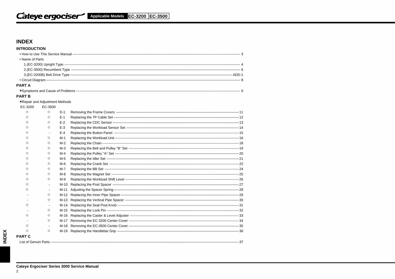
INDEXINTRODUCTION
• How to Use This Service Manual -------------------------------------------------------------------------------------------------------------------------------------------------- 3
• Name of Parts
1.(EC-3200) Upright Type --------------------------------------------------------------------------------------------------------------------------------------------------------- 4
2.(EC-3500) Recumbent Type --------------------------------------------------------------------------------------------------------------------------------------------------- 6
3.(EC-3200B) Belt Drive Type --------------------------------------------------------------------------------------------------------------------------------------------- ADD-1
• Circuit Diagram ------------------------------------------------------------------------------------------------------------------------------------------------------------------------- 8
PART A�Symptoms and Cause of Problems ----------------------------------------------------------------------------------------------------------------------------------------------- 9
PART B�Repair and Adjustment Methods
EC-3200 EC-3500
� � D-1 Removing the Frame Covers ----------------------------------------------------------------------------------------------------------- 11
� � E-1 Replacing the 7P Cable Set ------------------------------------------------------------------------------------------------------------- 12
� � E-2 Replacing the CDC Sensor -------------------------------------------------------------------------------------------------------------- 13
� � E-3 Replacing the Workload Sensor Set -------------------------------------------------------------------------------------------------- 14
� - E-4 Replacing the Button Panel ------------------------------------------------------------------------------------------------------------- 15
� � M-1 Replacing the Workload Unit ------------------------------------------------------------------------------------------------------------ 16
� � M-2 Replacing the Chain ----------------------------------------------------------------------------------------------------------------------- 18
� � M-3 Replacing the Belt and Pulley "B" Set ------------------------------------------------------------------------------------------------ 19
� � M-4 Replacing the Pulley "A" Set ------------------------------------------------------------------------------------------------------------ 20
� � M-5 Replacing the Idler Set -------------------------------------------------------------------------------------------------------------------21
� � M-6 Replacing the Crank Set -----------------------------------------------------------------------------------------------------------------22
� � M-7 Replacing the BB Set --------------------------------------------------------------------------------------------------------------------- 24
� � M-8 Replacing the Magnet Set --------------------------------------------------------------------------------------------------------------- 25
� � M-9 Replacing the Workload Shift Lever --------------------------------------------------------------------------------------------------- 26
� - M-10 Replacing the Post Spacer -------------------------------------------------------------------------------------------------------------- 27
� - M-11 Adjusting the Spacer Spring ------------------------------------------------------------------------------------------------------------- 28
- � M-12 Replacing the Inner Pipe Spacer ------------------------------------------------------------------------------------------------------- 29
- � M-13 Replacing the Vertical Pipe Spacer --------------------------------------------------------------------------------------------------- 30
� - M-14 Replacing the Seat Post Knob ---------------------------------------------------------------------------------------------------------- 31
- � M-15 Replacing the Lock Pin -------------------------------------------------------------------------------------------------------------------32
� � M-16 Replacing the Caster & Level Adjuster ----------------------------------------------------------------------------------------------- 33
- � M-17 Removing the EC-3200 Center Cover ------------------------------------------------------------------------------------------------ 34
� - M-18 Removing the EC-3500 Center Cover ------------------------------------------------------------------------------------------------ 35
� � M-19 Replacing the Handlebar Grip ---------------------------------------------------------------------------------------------------------- 36
PART CList of Genuin Parts --------------------------------------------------------------------------------------------------------------------------------------------------------------------37IN
DE
X
EC-3200 EC-3500
Cateye Ergociser Series 3000 Service Manual3
Applicable Models
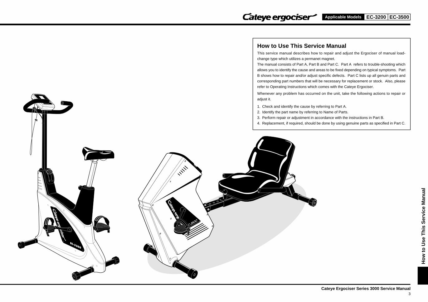
How to Use This Service ManualThis service manual describes how to repair and adjust the Ergociser of manual load-
change type which utilizes a permanet magnet.
The manual consists of Part A, Part B and Part C. Part A refers to trouble-shooting which
allows you to identify the cause and areas to be fixed depending on typical symptoms. Part
B shows how to repair and/or adjust specific defects. Part C lists up all genuin parts and
corresponding part numbers that will be necessary for replacement or stock. Also, please
refer to Operating Instructions which comes with the Cateye Ergociser.
Whenever any problem has occurred on the unit, take the following actions to repair or
adjust it.
1. Check and identify the cause by referring to Part A.
2. Identify the part name by referring to Name of Parts.
3. Perform repair or adjustment in accordance with the instructions in Part B.
4. Replacement, if required, should be done by using genuine parts as specified in Part C.
Ho
w t
o U
se T
his
Ser
vice
Man
ual
Cateye Ergociser Series 3000 Service Manual4
EC-3200Applicable Models
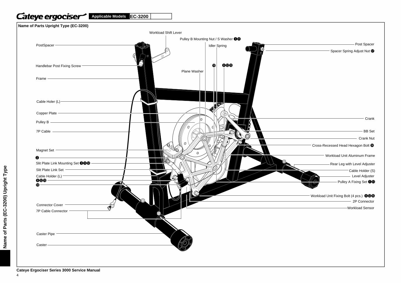
Name of Parts Upright Type (EC-3200)
Connector Cover
Pulley B Mounting Nut / S Washer 1q
Workload Shift Lever
Idler Spring
Plane Washer
Nam
e o
f Par
ts (E
C-3
200)
Up
rig
ht T
ype
PostSpacer
Handlebar Post Fixing Screw
Cable Holer (L)
Copper Plate
7P Cable
Magnet Set
Slit Plate Link Mounting Set 39w
Frame
Pulley B
Slit Plate Link Set
Cable Holder (L)
7P Cable Connector
Caster Pipe
Caster
Post Spacer
Spacer Spring Adjust Nut u
Crank
BB Set
Crank Nut
Cross-Recessed Head Hexagon Bolt r
Workload Unit Aluminum Frame
Rear Leg with Level Adjuster
Cable Holder (S)
Level Adjuster
Pulley A Fixing Set 1q
Workload Unit Fixing Bolt (4 pcs.) 8wt
2P Connector
Workload Sensor
i
8wt
2
o 8wt
EC-3200
Cateye Ergociser Series 3000 Service Manual5
Applicable Models
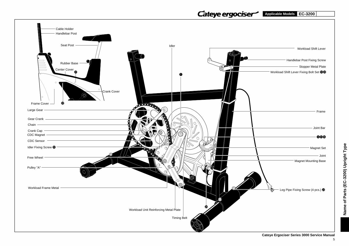
Cable Holder
Handlebar Post
Seat Post
Frame Cover
Center Cover
Crank Cover
Idler
Workload Unit Reinforcing Metal Plate
Timing Belt
Workload Shift Lever Fixing Bolt Set 0p
Nam
e o
f Par
ts (E
C-3
200)
Up
rig
ht T
ype
Large Gear
Gear Crank
Chain
Crank CapCDC Magnet
CDC Sensor
Pulley "A"
Idler Fixing Screw 0
Free Wheel
Workload Frame Metal
Workload Shift Lever
Handlebar Post Fixing Screw
Stopper Metal Plate
Frame
Joint Bar
Magnet Set
Joint
Magnet Mounting Base
Leg Pipe Fixing Screw (4 pcs.) d
Rubber Base
s
a1
f
6ey
Cateye Ergociser Series 3000 Service Manual6
EC-3500Applicable Models
Pulley "B" Mounting Nut/Spring Washer 1q
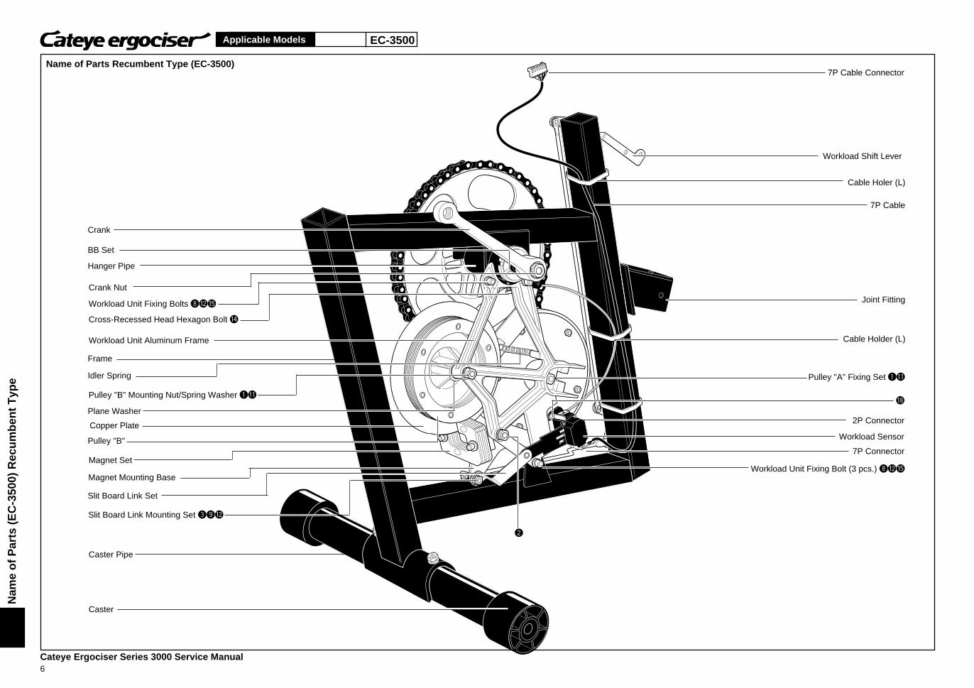
Name of Parts Recumbent Type (EC-3500)
Nam
e o
f P
arts
(E
C-3
500)
Rec
um
ben
t T
ype
Crank
Hanger Pipe
Crank Nut
Workload Unit Fixing Bolts 8wt
Cross-Recessed Head Hexagon Bolt r
Workload Unit Aluminum Frame
Frame
Idler Spring
Plane Washer
Copper Plate
Pulley "B"
Magnet Mounting Base
Slit Board Link Set
Slit Board Link Mounting Set 39w
Caster
Caster Pipe
Magnet Set
BB Set
7P Cable Connector
Workload Shift Lever
Cable Holer (L)
7P Cable
Joint Fitting
Cable Holder (L)
Pulley "A" Fixing Set 1q
2P Connector
7P Connector
Workload Sensor
Workload Unit Fixing Bolt (3 pcs.) 8wt
2
i
EC-3500
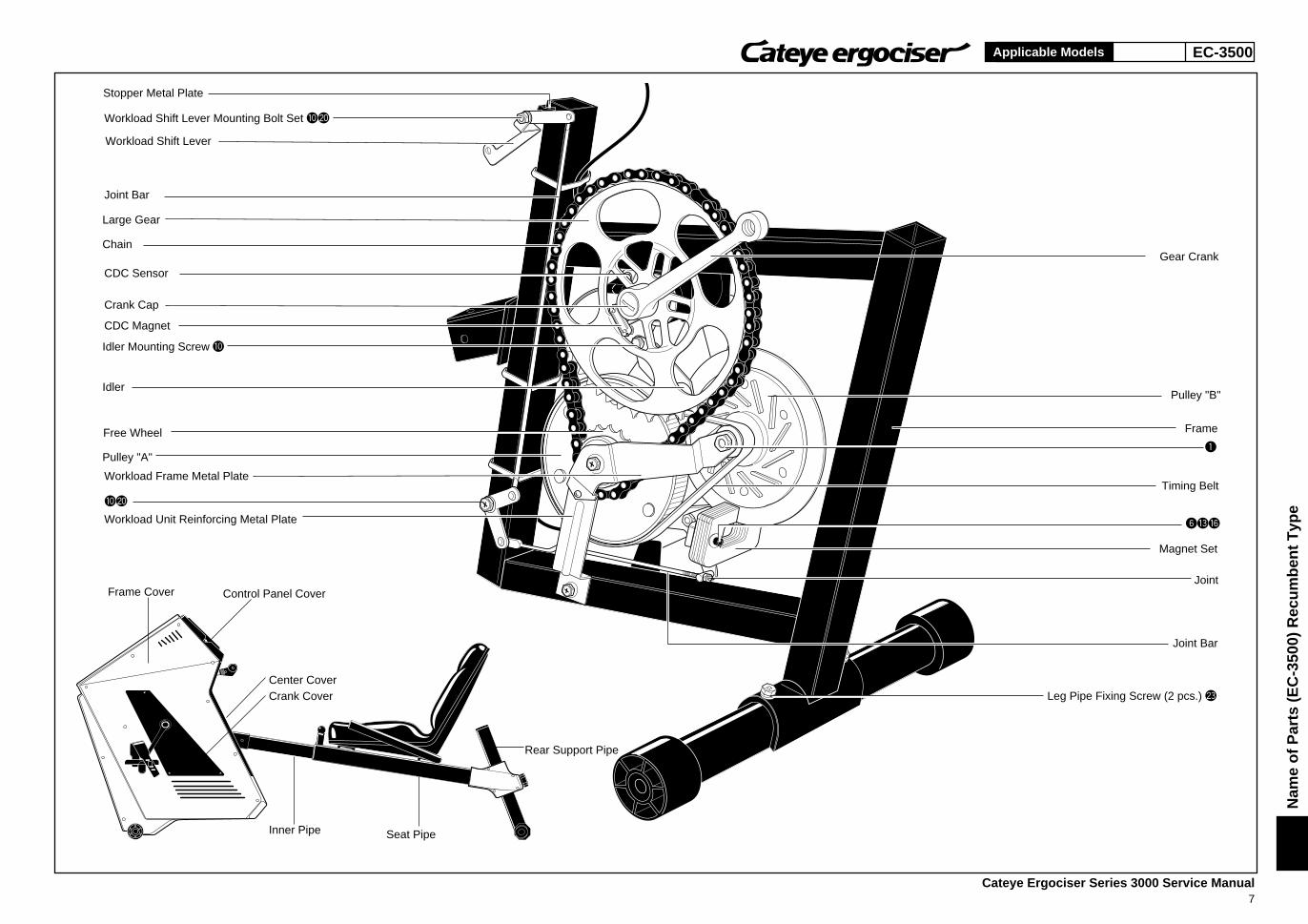
Cateye Ergociser Series 3000 Service Manual7
Applicable Models
Frame Cover Control Panel Cover
Center CoverCrank Cover
Seat Pipe
Rear Support Pipe
Inner Pipe
Nam
e o
f P
arts
(E
C-3
500)
Rec
um
ben
t T
ype
Stopper Metal Plate
Workload Shift Lever Mounting Bolt Set 0p
Workload Shift Lever
Joint Bar
Large Gear
Chain
CDC Sensor
Crank Cap
CDC Magnet
Free Wheel
Pulley "A"
Workload Frame Metal Plate
Workload Unit Reinforcing Metal Plate
Idler
Idler Mounting Screw 0
Gear Crank
Pulley "B"
Frame
Timing Belt
Magnet Set
Joint
Joint Bar
Leg Pipe Fixing Screw (2 pcs.) d
1
6ey
0p
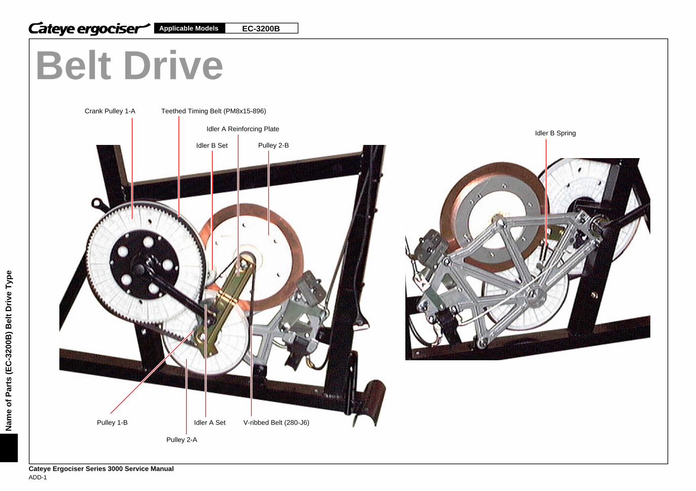
EC-3200BApplicable Models
Cateye Ergociser Series 3000 Service ManualADD-1
Nam
e o
f P
arts
(E
C-3
200B
) B
elt
Dri
ve T
ype
Crank Pulley 1-A Teethed Timing Belt (PM8x15-896)
Idler A SetPulley 1-B
Pulley 2-A
Pulley 2-BIdler B Set
Idler A Reinforcing Plate
V-ribbed Belt (280-J6)
Idler B Spring
Belt Drive
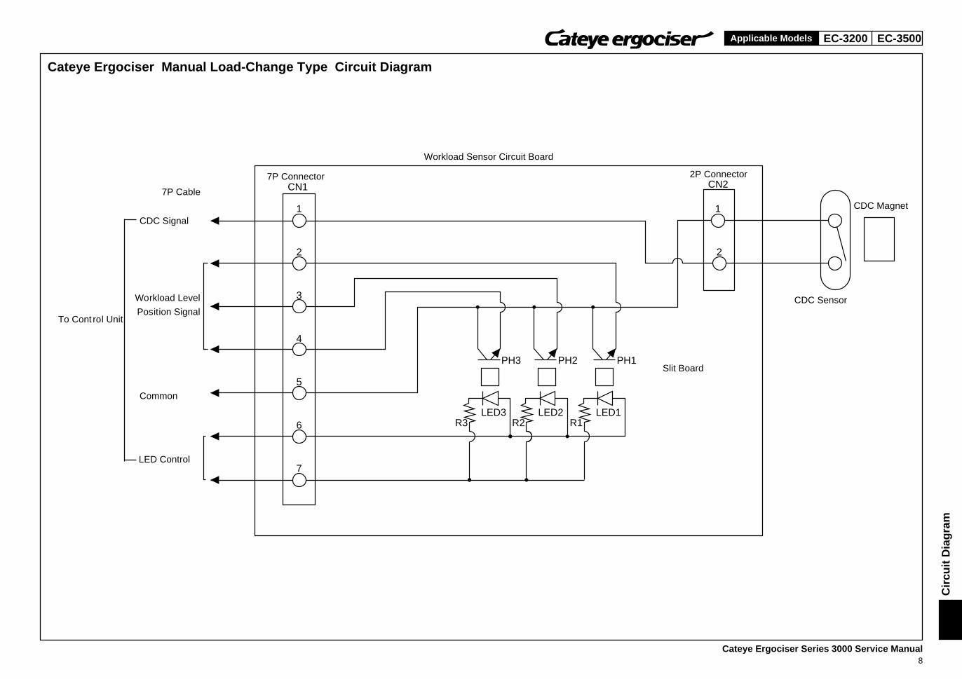
EC-3200 EC-3500Applicable Models
CN1 CN2
1
2
3
4
5
6
7
1
2
PH3 PH2 PH1
LED3R3
LED2R2
LED1R1
Cateye Ergociser Manual Load-Change Type Circuit Diagram
7P Cable
Slit Board
CDC Magnet
CDC Sensor
Workload Sensor Circuit Board
7P Connector 2P Connector
Common
LED Control
CDC Signal
Cir
cuit
Dia
gra
m
To Cont rol Unit
Workload Level
Position Signal
Cateye Ergociser Series 3000 Service Manual8
EC-3200 EC-3500Applicable Models
Symptom of Problem Check Method/Cause of Problem Remedy
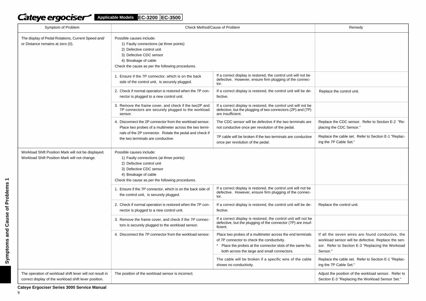
The display of Pedal Rotations, Current Speed and/
or Distance remains at zero (0).
Possible causes include:
1) Faulty connections (at three points)
2) Defective control unit
3) Defective CDC sensor
4) Breakage of cable
Check the cause as per the following procedures.
1. Ensure if the 7P connector, which is on the back
side of the control unit, is securely plugged.
If a correct display is restored, the control unit will not bedefective. However, ensure firm plugging of the connec-tor.
2. Check if normal operation is restored when the 7P con-
nector is plugged to a new control unit.
If a correct display is restored, the control unit will be de-
fective.Replace the control unit.
3. Remove the frame cover, and check if the two2P and7P connectors are securely plugged to the workloadsensor.
If a correct display is restored, the control unit will not bedefective, but the plugging of two connectors (2P) and (7P)are insufficient.
4. Disconnect the 2P connector from the workload sensor.
Place two probes of a multimeter across the two termi-
nals of the 2P connector. Rotate the pedal and check if
the two terminals are conductive.
The CDC sensor will be defective if the two terminals are
not conductive once per revolution of the pedal.
Replace the CDC sensor. Refer to Section E-2 "Re-
placing the CDC Sensor."
7P cable will be broken if the two terminals are conductive
once per revolution of the pedal.
Replace the cable set. Refer to Section E-1 "Replac-
ing the 7P Cable Set."
Workload Shift Position Mark will not be displayed.
Workload Shift Position Mark will not change.
Possible causes include:
1) Faulty connections (at three points)
2) Defective control unit
3) Defective CDC sensor
4) Breakage of cable
Check the cause as per the following procedures.
1. Ensure if the 7P connector, which is on the back side of
the control unit, is securely plugged.
If a correct display is restored, the control unit will not bedefective. However, ensure firm plugging of the connec-tor.
2. Check if normal operation is restored when the 7P con-
nector is plugged to a new control unit.
If a correct display is restored, the control unit will be de-
fective.
Replace the control unit.
3. Remove the frame cover, and check if the 7P connec-
tors is securely plugged to the workload sensor.
If a correct display is restored, the control unit will not bedefective, but the plugging of the connector (7P) are insuf-ficient.
4. Disconnect the 7P connector from the workload sensor. Place two probes of a multimeter across the end terminals
of 7P connector to check the conductivity.
* Place the probes at the connector slots of the same No.
both across the large and small connectors.
If all the seven wires are found conductive, the
workload sensor will be defective. Replace the sen-
sor. Refer to Section E-3 "Replacing the Workioad
Sensor."
Replace the cable set. Refer to Section E-1 "Replac-
ing the 7P Cable Set."
The cable will be broken if a specific wire of the cable
shows no conductivity.
The operation of workload shift lever will not result in
correct display of the workload shift lever position.
The position of the workload sensor is incorrect. Adjust the position of the workload sensor. Refer to
Section E-3 "Replacing the Workload Sensor Set."
Sym
pto
ms
and
Cau
se o
f P
rob
lem
s 1
Cateye Ergociser Series 3000 Service Manual9
EC-3200 EC-3500Applicable Models
Symptom of Problem Check Method/Cause of Problem Remedy
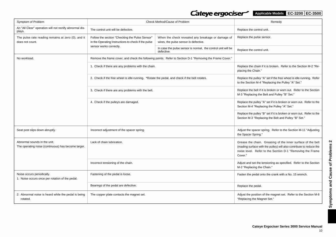
The control unit will be defective. Replace the control unit.
The pulse rate reading remains at zero (0), and it
does not count.
Follow the section "Checking the Pulse Sensor"
in the Operating Instructions to check if the pulse
sensor works correctly.
When the check revealed any breakage or damage of
wires, the pulse sensor is defective.
Replace the pulse sensor.
Replace the control unit.
No workload. Remove the frame cover, and check the following points. Refer to Section D-1 "Removing the Frame Cover."
Replace the chain if it is broken. Refer to the Section M-2 "Re-
placing the Chain."
2. Check if the free wheel is idle-running. *Rotate the pedal, and check if the belt rotates.
4. Check if the pulleys are damaged. Replace the pulley "A" set if it is broken or worn out. Refer to the
Section M-4 "Replacing the Pulley "A" Set."
1. Check if there are any problems with the chain.
Replace the pulley "A" set if the free wheel is idle-running. Refer
to the Section M-4 "Replacing the Pulley "A" Set."
3. Check if there are any problems with the belt. Replace the belt if it is broken or worn out. Refer to the Section
M-3 "Replacing the Belt and Pulley "B" Set."
Replace the pulley "B" set if it is broken or worn out. Refer to the
Section M-3 "Replacing the Belt and Pulley "B" Set."
Seat post slips down abruptly. Incorrect adjustment of the spacer spring. Adjust the spacer spring. Refer to the Section M-11 "Adjusting
the Spacer Spring."
Abnormal sounds in the unit.
The operating noise (continuous) has become larger.
Adjust and set the tensioning as specified. Refer to the Section
M-2 "Replacing the Chain."
Noise occurs periodically.
1. Noise occurs once per rotation of the pedal.
2. Abnormal noise is heard while the pedal is being
rotated.
The copper plate contacts the magnet set. Adjust the position of the magnet set. Refer to the Section M-8
"Replacing the Magnet Set."
Sym
pto
ms
and
Cau
se o
f P
rob
lem
s 2
An "All Clear" operation will not rectify abnormal dis-plays.
In case the pulse sensor is normal, the control unit will bedefective.
Grease the chain. Greasing of the inner surface of the belt
(mading surface with the pulley) will also contribute to reduce the
noise level. Refer to the Section D-1 "Removing the Frame
Cover."
Incorrect tensioning of the chain.
Fasten the pedal onto the crank with a No. 15 wrench.
Replace the pedal.
Fastening of the pedal is loose.
Bearings of the pedal are defective.
Lack of chain lubrication.
Cateye Ergociser Series 3000 Service Manual10
EC-3200 EC-3500
Cateye Ergociser Series 3000 Service Manual11
Applicable Models
D-1
D-1
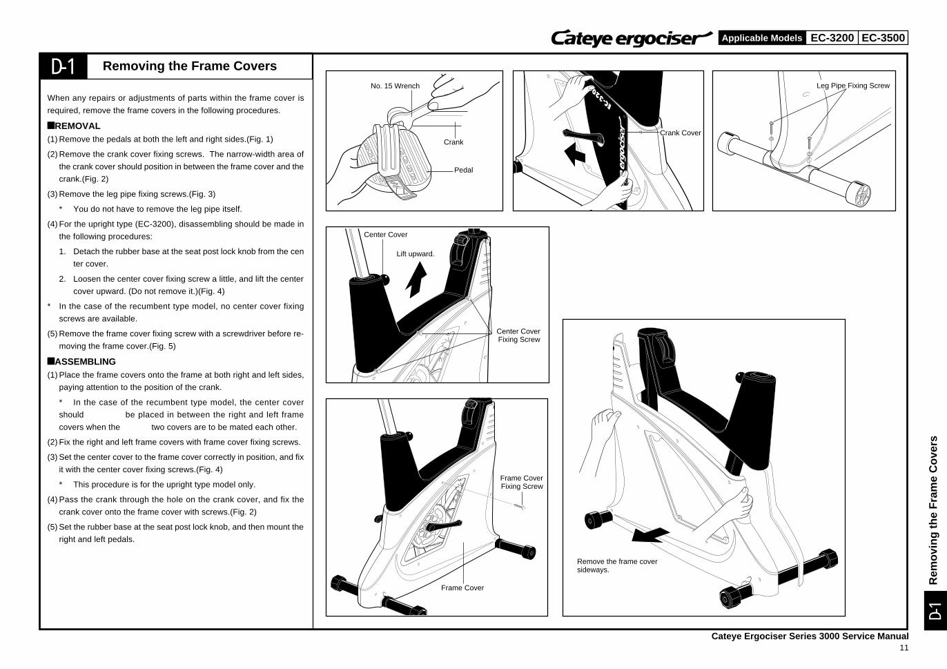
When any repairs or adjustments of parts within the frame cover is
required, remove the frame covers in the following procedures.
àREMOVAL(1) Remove the pedals at both the left and right sides.(Fig. 1)
(2) Remove the crank cover fixing screws. The narrow-width area of
the crank cover should position in between the frame cover and the
crank.(Fig. 2)
(3) Remove the leg pipe fixing screws.(Fig. 3)
* You do not have to remove the leg pipe itself.
(4) For the upright type (EC-3200), disassembling should be made in
the following procedures:
1. Detach the rubber base at the seat post lock knob from the cen
ter cover.
2. Loosen the center cover fixing screw a little, and lift the center
cover upward. (Do not remove it.)(Fig. 4)
* In the case of the recumbent type model, no center cover fixing
screws are available.
(5) Remove the frame cover fixing screw with a screwdriver before re-
moving the frame cover.(Fig. 5)
àASSEMBLING(1) Place the frame covers onto the frame at both right and left sides,
paying attention to the position of the crank.
* In the case of the recumbent type model, the center cover
should be placed in between the right and left frame
covers when the two covers are to be mated each other.
(2) Fix the right and left frame covers with frame cover fixing screws.
(3) Set the center cover to the frame cover correctly in position, and fix
it with the center cover fixing screws.(Fig. 4)
* This procedure is for the upright type model only.
(4) Pass the crank through the hole on the crank cover, and fix the
crank cover onto the frame cover with screws.(Fig. 2)
(5) Set the rubber base at the seat post lock knob, and then mount the
right and left pedals.
Removing the Frame CoversNo. 15 Wrench
Crank
Pedal
Rem
ovin
g th
e F
ram
e C
over
s
Crank Cover
Center Cover
Lift upward.
Leg Pipe Fixing Screw
Center CoverFixing Screw
Frame CoverFixing Screw
Frame Cover
Remove the frame coversideways.
EC-3200 EC-3500
Cateye Ergociser Series 3000 Service Manual12
Applicable Models
E-1
E-1
Fig.1 Fig.2 Fig.3
Fig.4 Fig.5
Fig.6 Fig.7
Control Unit
78cm for Upright Type
Fig.8 Fig.9
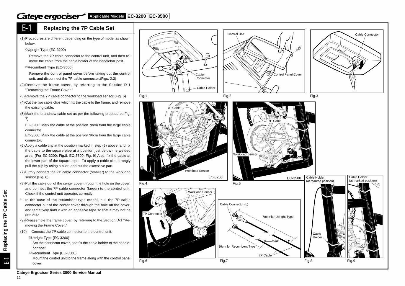
Replacing the 7P Cable Set
(1) Procedures are different depending on the type of model as shownbelow:
TUpright Type (EC-3200)
Remove the 7P cable connector to the control unit, and then re-move the cable from the cable holder of the handlebar post.
TRecumbent Type (EC-3500)
Remove the control panel cover before taking out the controlunit, and disconnect the 7P cable connector.(Figs. 2,3)
(2) Remove the frame cover, by referring to the Section D-1"Removing the Frame Cover."
(3) Remove the 7P cable connector to the workload sensor.(Fig. 6)
(4) Cut the two cable clips which fix the cable to the frame, and removethe existing cable.
(5) Mark the brandnew cable set as per the following procedures.Fig.7)
EC-3200: Mark the cable at the position 78cm from the large cable
connector.EC-3500: Mark the cable at the position 36cm from the large cableconnector.
(6) Apply a cable clip at the position marked in step (5) above, and fixthe cable to the square pipe at a position just below the weldedarea. (For EC-3200: Fig.8, EC-3500: Fig. 9) Also, fix the cable at
the lower part of the square pipe. To apply a cable clip, stronglypull the clip by using a plier, and cut the excessive part.
(7) Firmly connect the 7P cable connector (smaller) to the workloadsensor.(Fig. 6)
(8) Pull the cable out of the center cover through the hole on the cover,
and connect the 7P cable connector (larger) to the control unit.Check if the control unit operates correctly.
* In the case of the recumbent type model, pull the 7P cable
connector out of the center cover through the hole on the cover,and tentatively hold it with an adhesive tape so that it may not beretructed.
(9) Reassemble the frame cover, by referring to the Section D-1 "Re-moving the Frame Cover."
(10) Connect the 7P cable connector to the control unit.
TUpright Type (EC-3200)Set the connector cover, and fix the cable holder to the handle-
bar post.TRecumbent Type (EC-3500)
Mount the control unit to the frame along with the control panel
cover.
CableConnector
Cable Holder
Control Panel Cover
Cable Connector
7P Cable
Workload Sensor
Workload Sensor
7P Cable
7P Connector
Workload Sensor
Cable Connector (L)
36cm for Recumbent Type
Mark
7P Cable
CableHolder
EC-3200 EC-3500
Rep
laci
ng th
e 7P
Cab
le S
et
Cable Holder(at marked position)
Cable Holder(at marked position)
EC-3200 EC-3500
Cateye Ergociser Series 3000 Service Manual13
Applicable Models
2PConnector
E-2
E-2
Fig.1 Fig.2
Fig.3 Fig.4
Fig.5
Fig.6 Fig.7
CDC Sensor
CDC Sensor
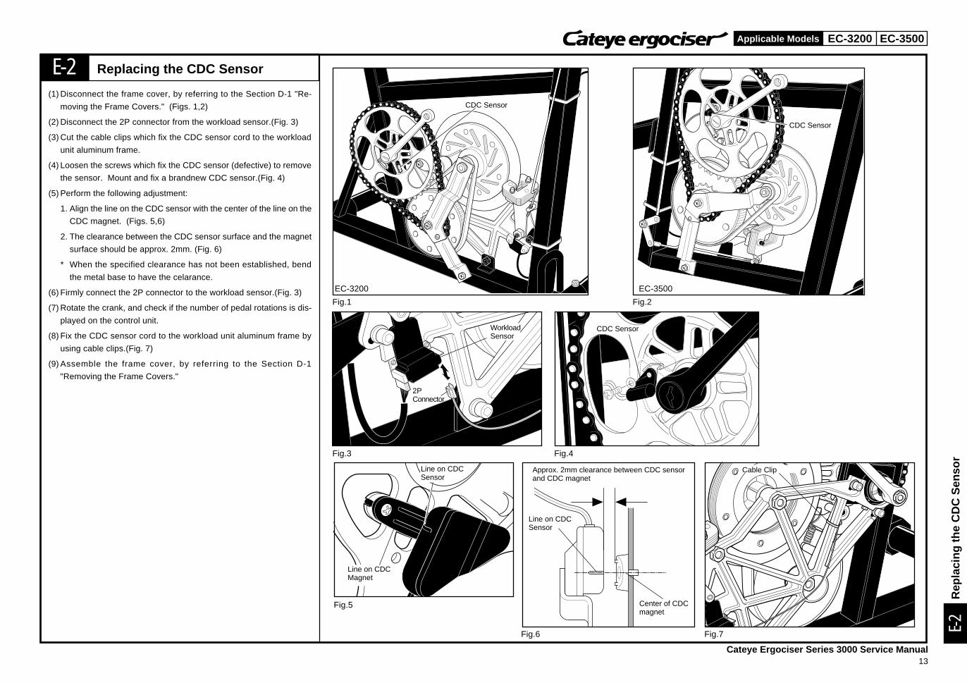
Replacing the CDC Sensor
(1) Disconnect the frame cover, by referring to the Section D-1 "Re-
moving the Frame Covers." (Figs. 1,2)
(2) Disconnect the 2P connector from the workload sensor.(Fig. 3)
(3) Cut the cable clips which fix the CDC sensor cord to the workload
unit aluminum frame.
(4) Loosen the screws which fix the CDC sensor (defective) to remove
the sensor. Mount and fix a brandnew CDC sensor.(Fig. 4)
(5) Perform the following adjustment:
1. Align the line on the CDC sensor with the center of the line on the
CDC magnet. (Figs. 5,6)
2. The clearance between the CDC sensor surface and the magnet
surface should be approx. 2mm. (Fig. 6)
* When the specified clearance has not been established, bend
the metal base to have the celarance.
(6) Firmly connect the 2P connector to the workload sensor.(Fig. 3)
(7) Rotate the crank, and check if the number of pedal rotations is dis-
played on the control unit.
(8) Fix the CDC sensor cord to the workload unit aluminum frame by
using cable clips.(Fig. 7)
(9) Assemble the frame cover, by referring to the Section D-1
"Removing the Frame Covers."
CDC Sensor
WorkloadSensor
Line on CDCMagnet
Line on CDCSensor
Line on CDCSensor
Center of CDCmagnet
Cable Clip
EC-3500EC-3200
Rep
laci
ng th
e C
DC
Sen
sor
Approx. 2mm clearance between CDC sensorand CDC magnet
EC-3200 EC-3500
Cateye Ergociser Series 3000 Service Manual14
Applicable Models
E-3
E-3
Fig.1 Fig.2
Fig.3 Fig.4
Fig.5
Fig.6
Workload Sensor
7PConnector
2PConnector
2mm
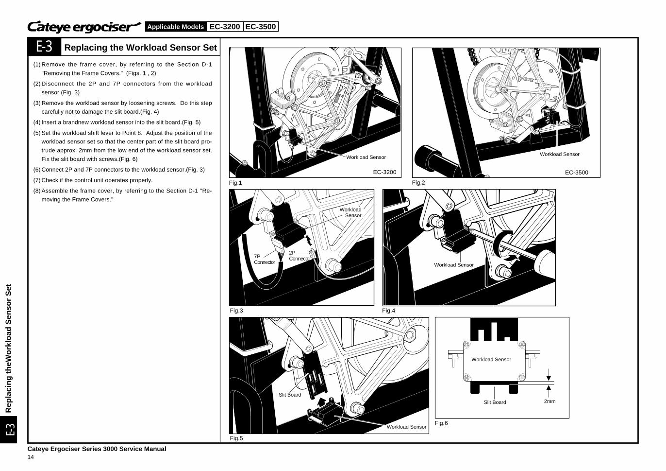
(1) Remove the frame cover, by referring to the Section D-1
"Removing the Frame Covers." (Figs. 1 , 2)
(2) Disconnect the 2P and 7P connectors from the workload
sensor.(Fig. 3)
(3) Remove the workload sensor by loosening screws. Do this step
carefully not to damage the slit board.(Fig. 4)
(4) Insert a brandnew workload sensor into the slit board.(Fig. 5)
(5) Set the workload shift lever to Point 8. Adjust the position of the
workload sensor set so that the center part of the slit board pro-
trude approx. 2mm from the low end of the workload sensor set.
Fix the slit board with screws.(Fig. 6)
(6) Connect 2P and 7P connectors to the workload sensor.(Fig. 3)
(7) Check if the control unit operates properly.
(8) Assemble the frame cover, by referring to the Section D-1 "Re-
moving the Frame Covers."
EC-3500
Workload Sensor
EC-3200
WorkloadSensor
Workload Sensor
Workload Sensor
Slit Board
Workload Sensor
Slit Board
Rep
laci
ng th
eWor
kloa
d S
enso
r S
et
Replacing the Workload Sensor Set
EC-3200
Cateye Ergociser Series 3000 Service Manual15
Applicable Models
E-4
E-4
C
Fig.1
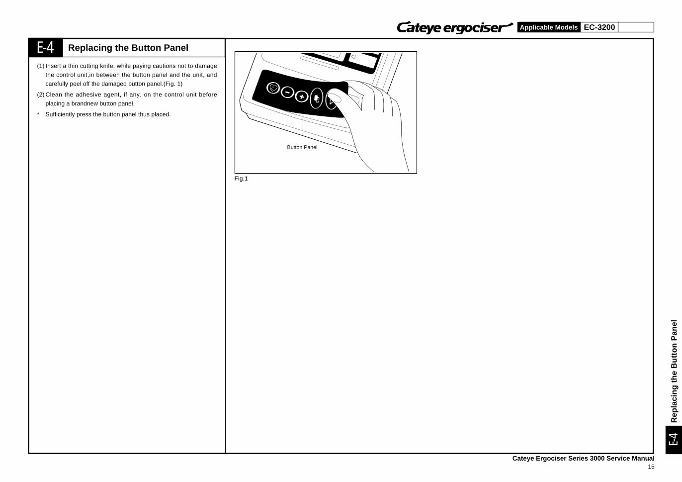
Replacing the Button Panel
(1) Insert a thin cutting knife, while paying cautions not to damage
the control unit,in between the button panel and the unit, and
carefully peel off the damaged button panel.(Fig. 1)
(2) Clean the adhesive agent, if any, on the control unit before
placing a brandnew button panel.
* Sufficiently press the button panel thus placed.
Button Panel
Rep
laci
ng th
e B
utto
n P
anel
EC-3200 EC-3500
Cateye Ergociser Series 3000 Service Manual16
Applicable Models
M-1
M-1
Fig.1 Fig.2
Fig.3
Fig.4
Fig.5 Fig.6
Workload Unit
EC-3200
Workload Unit
EC-3500
Joint Bar
Joint
Joint Nut
Nut Pulley "B" Shaft
Pulley "A" Shaft
Bolt
Workload FrameMetal Base
Bolt
Workload Unit ReinforcingMetal Base Frame
Aluminum Frame
WorkloadUnit
Workload Fixing Bolt
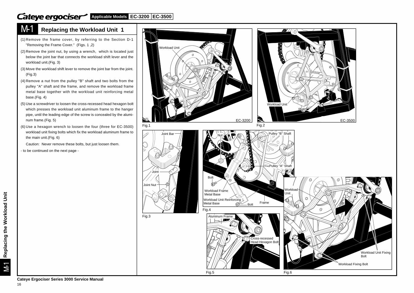
Replacing the Workload Unit 1
(1) Remove the frame cover, by referring to the Section D-1
"Removing the Frame Cover." (Figs. 1 ,2)
(2) Remove the joint nut, by using a wrench, which is located just
below the joint bar that connects the workload shift lever and the
workload unit.(Fig. 3)
(3) Move the workload shift lever to remove the joint bar from the joint.
(Fig.3)
(4) Remove a nut from the pulley "B" shaft and two bolts from the
pulley "A" shaft and the frame, and remove the workload frame
metal base together with the workload unit reinforcing metal
base.(Fig. 4)
(5) Use a screwdriver to loosen the cross-recessed head hexagon bolt
which presses the workload unit aluminum frame to the hanger
pipe, until the leading edge of the screw is concealed by the alumi-
num frame.(Fig. 5)
(6) Use a hexagon wrench to loosen the four (three for EC-3500)
workload unit fixing bolts which fix the workload aluminum frame to
the main unit.(Fig. 6)
Caution: Never remove these bolts, but just loosen them.
- to be continued on the next page -
Rep
laci
ng th
e W
orkl
oad
Uni
t
Cross-recessedHead Hexagon Bolt
Workload Unit FixingBolt
EC-3200 EC-3500
Cateye Ergociser Series 3000 Service Manual17
Applicable Models
M-1
M-1
Fig.7
Fig.8
Fig.9 Fig.10
Fig.11
Upper Part of Large Gear
Chain
Workload Sensor
2PConnector
7PConnector
Workload Unit FixingBolt
Workload Unit Fixing Bolt
Upper Part of Large Gear
Chain
Slack of 3 to 7mm
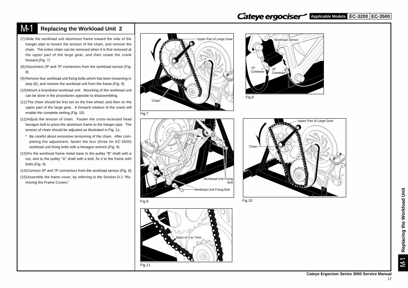
Replacing the Workload Unit 2
(7) Slide the workload unit aluminum frame toward the side of the
hanger pipe to loosen the tension of the chain, and remove the
chain. The entire chain can be removed when it is first removed at
the upper part of the large gear, and then rotate the crank
forward.(Fig. 7)
(8) Disconnect 2P and 7P connectors from the workload sensor.(Fig.
8)
(9) Remove four workload unit fixing bolts which has been loosening in
step (6), and remove the workload unit from the frame.(Fig. 9)
(10)Mount a brandnew workload unit. Mounting of the workload unit
can be done in the procedures opposite to disassembling.
(11)The chain should be first set on the free wheel, and then on the
upper part of the large gear. A forward rotation of the crank will
enable the complete setting.(Fig. 10)
(12)Adjust the tension of chain. Fasten the cross-recessed head
hexagon bolt to press the aluminum frame to the hanger pipe. The
tension of chain should be adjusted as illustrated in Fig. 11.
* Be careful about excessive tensioning of the chain. After com-
pleting the adjustment, fasten the four (three for EC-3500)
workload unit fixing bolts with a hexagon wrench.(Fig. 9)
(13)Fix the workload frame metal base to the pulley "B" shaft with a
nut, and to the pulley "A" shaft with a bolt, fix it to the frame with
bolts.(Fig. 4)
(14)Connect 2P and 7P connectors from the workload sensor.(Fig. 8)
(15)Assemble the frame cover, by referring to the Section D-1 "Re-
moving the Frame Covers."
Rep
laci
ng th
e W
orkl
oad
Uni
t
EC-3200 EC-3500
Cateye Ergociser Series 3000 Service Manual18
Applicable Models
M-2
M-2
Fig.1 Fig.2
Fig.3
EC-3200
Fig.4
Fig.6 Fig.7
Fig.5
Chain
Chain
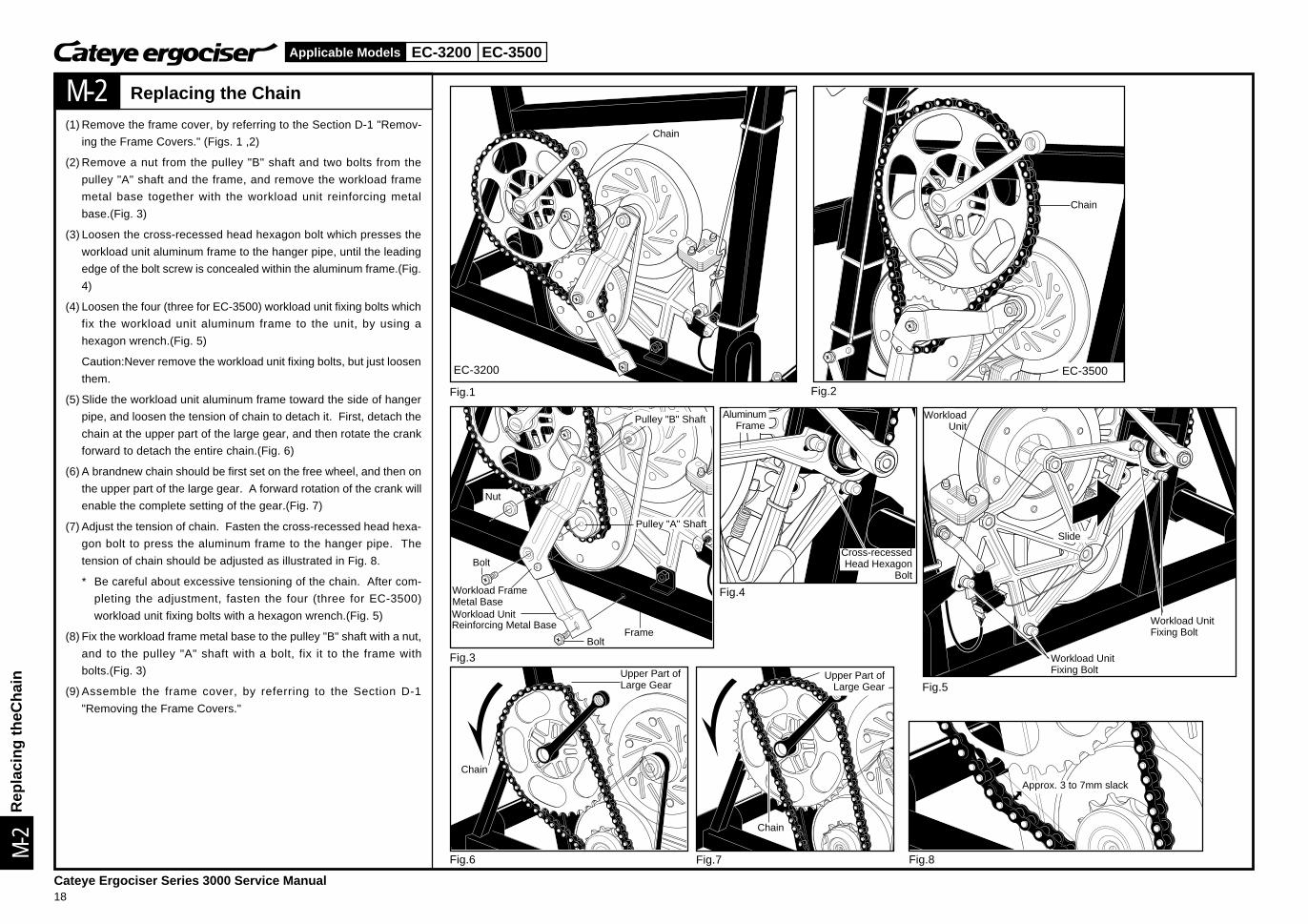
Replacing the Chain
(1) Remove the frame cover, by referring to the Section D-1 "Remov-
ing the Frame Covers." (Figs. 1 ,2)
(2) Remove a nut from the pulley "B" shaft and two bolts from the
pulley "A" shaft and the frame, and remove the workload frame
metal base together with the workload unit reinforcing metal
base.(Fig. 3)
(3) Loosen the cross-recessed head hexagon bolt which presses the
workload unit aluminum frame to the hanger pipe, until the leading
edge of the bolt screw is concealed within the aluminum frame.(Fig.
4)
(4) Loosen the four (three for EC-3500) workload unit fixing bolts which
fix the workload unit aluminum frame to the unit, by using a
hexagon wrench.(Fig. 5)
Caution:Never remove the workload unit fixing bolts, but just loosen
them.
(5) Slide the workload unit aluminum frame toward the side of hanger
pipe, and loosen the tension of chain to detach it. First, detach the
chain at the upper part of the large gear, and then rotate the crank
forward to detach the entire chain.(Fig. 6)
(6) A brandnew chain should be first set on the free wheel, and then on
the upper part of the large gear. A forward rotation of the crank will
enable the complete setting of the gear.(Fig. 7)
(7) Adjust the tension of chain. Fasten the cross-recessed head hexa-
gon bolt to press the aluminum frame to the hanger pipe. The
tension of chain should be adjusted as illustrated in Fig. 8.
* Be careful about excessive tensioning of the chain. After com-
pleting the adjustment, fasten the four (three for EC-3500)
workload unit fixing bolts with a hexagon wrench.(Fig. 5)
(8) Fix the workload frame metal base to the pulley "B" shaft with a nut,
and to the pulley "A" shaft with a bolt, fix it to the frame with
bolts.(Fig. 3)
(9) Assemble the frame cover, by referring to the Section D-1
"Removing the Frame Covers."
EC-3500
Nut
Bolt
Workload FrameMetal Base
Bolt
Pulley "B" Shaft
Pulley "A" Shaft
Frame
AluminumFrame
Cross-recessedHead Hexagon
Bolt
WorkloadUnit
Slide
Workload UnitFixing Bolt
Workload UnitFixing BoltUpper Part of
Large Gear
Chain
Upper Part ofLarge Gear
Chain
Fig.8
Approx. 3 to 7mm slack
Rep
laci
ng th
eCha
in
Workload UnitReinforcing Metal Base
EC-3200 EC-3500
Cateye Ergociser Series 3000 Service Manual19
Applicable Models
M-3
M-3
Fig.1 Fig.2
Fig.4 Fig.5
Fig.6 Fig.7 Fig.8
Fig.3
Pulley "A"
Pulley "B"
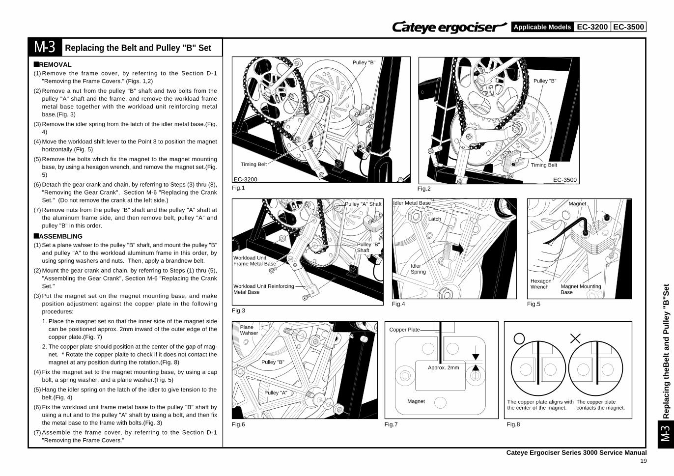
Replacing the Belt and Pulley "B" Set
àREMOVAL(1) Remove the frame cover, by referring to the Section D-1
"Removing the Frame Covers." (Figs. 1,2)
(2) Remove a nut from the pulley "B" shaft and two bolts from thepulley "A" shaft and the frame, and remove the workload framemetal base together with the workload unit reinforcing metalbase.(Fig. 3)
(3) Remove the idler spring from the latch of the idler metal base.(Fig.4)
(4) Move the workload shift lever to the Point 8 to position the magnethorizontally.(Fig. 5)
(5) Remove the bolts which fix the magnet to the magnet mountingbase, by using a hexagon wrench, and remove the magnet set.(Fig.5)
(6) Detach the gear crank and chain, by referring to Steps (3) thru (8),"Removing the Gear Crank", Section M-6 "Replacing the CrankSet." (Do not remove the crank at the left side.)
(7) Remove nuts from the pulley "B" shaft and the pulley "A" shaft atthe aluminum frame side, and then remove belt, pulley "A" andpulley "B" in this order.
àASSEMBLING(1) Set a plane wahser to the pulley "B" shaft, and mount the pulley "B"
and pulley "A" to the workload aluminum frame in this order, byusing spring washers and nuts. Then, apply a brandnew belt.
(2) Mount the gear crank and chain, by referring to Steps (1) thru (5),"Assembling the Gear Crank", Section M-6 "Replacing the CrankSet."
(3) Put the magnet set on the magnet mounting base, and makeposition adjustment against the copper plate in the followingprocedures:
1. Place the magnet set so that the inner side of the magnet sidecan be positioned approx. 2mm inward of the outer edge of thecopper plate.(Fig. 7)
2. The copper plate should position at the center of the gap of mag-net. * Rotate the copper plalte to check if it does not contact themagnet at any position during the rotation.(Fig. 8)
(4) Fix the magnet set to the magnet mounting base, by using a capbolt, a spring washer, and a plane washer.(Fig. 5)
(5) Hang the idler spring on the latch of the idler to give tension to thebelt.(Fig. 4)
(6) Fix the workload unit frame metal base to the pulley "B" shaft byusing a nut and to the pulley "A" shaft by using a bolt, and then fixthe metal base to the frame with bolts.(Fig. 3)
(7) Assemble the frame cover, by referring to the Section D-1"Removing the Frame Covers."
Pulley "B"
EC-3200
Timing Belt
EC-3500
Timing Belt
Pulley "B"
Workload UnitFrame Metal Base
Pulley "A" Shaft
Pulley "B"Shaft
Idler Metal Base
Latch
IdlerSpring
Magnet
PlaneWahser
Approx. 2mm
Copper Plate
Rep
laci
ng th
eBel
t and
Pul
ley
"B"S
et
Workload Unit ReinforcingMetal Base
Magnet The copper plate aligns withthe center of the magnet.
The copper platecontacts the magnet.
Magnet MountingBase
HexagonWrench
EC-3200 EC-3500
Cateye Ergociser Series 3000 Service Manual20
Applicable Models
M-4
M-4
Fig.1 Fig.2
EC-3200
Pulley "A"
EC-3500
Pulley "A"
Fig.3
Fig.4 Fig.5
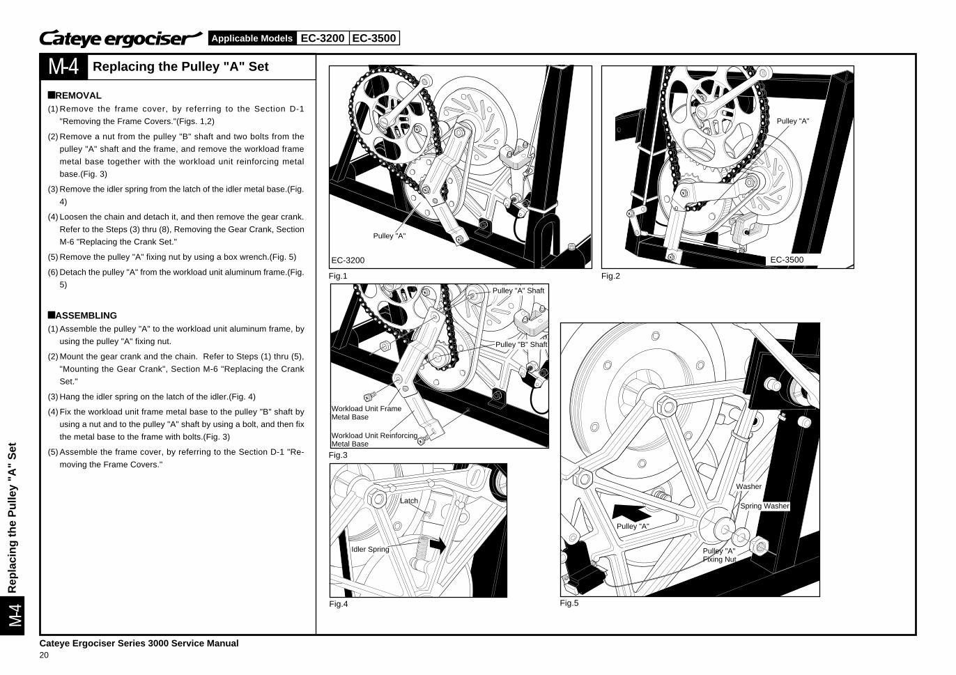
Replacing the Pulley "A" Set
àREMOVAL(1) Remove the frame cover, by referring to the Section D-1
"Removing the Frame Covers."(Figs. 1,2)
(2) Remove a nut from the pulley "B" shaft and two bolts from the
pulley "A" shaft and the frame, and remove the workload frame
metal base together with the workload unit reinforcing metal
base.(Fig. 3)
(3) Remove the idler spring from the latch of the idler metal base.(Fig.
4)
(4) Loosen the chain and detach it, and then remove the gear crank.
Refer to the Steps (3) thru (8), Removing the Gear Crank, Section
M-6 "Replacing the Crank Set."
(5) Remove the pulley "A" fixing nut by using a box wrench.(Fig. 5)
(6) Detach the pulley "A" from the workload unit aluminum frame.(Fig.
5)
àASSEMBLING(1) Assemble the pulley "A" to the workload unit aluminum frame, by
using the pulley "A" fixing nut.
(2) Mount the gear crank and the chain. Refer to Steps (1) thru (5),
"Mounting the Gear Crank", Section M-6 "Replacing the Crank
Set."
(3) Hang the idler spring on the latch of the idler.(Fig. 4)
(4) Fix the workload unit frame metal base to the pulley "B" shaft by
using a nut and to the pulley "A" shaft by using a bolt, and then fix
the metal base to the frame with bolts.(Fig. 3)
(5) Assemble the frame cover, by referring to the Section D-1 "Re-
moving the Frame Covers."
Workload Unit FrameMetal Base
Workload Unit ReinforcingMetal Base
Pulley "A" Shaft
Pulley "B" Shaft
Latch
Idler Spring
Spring Washer
Washer
Pulley "A"Fixing Nut
Pulley "A"
Rep
laci
ng th
e P
ulle
y "A
" S
et
EC-3200 EC-3500
Cateye Ergociser Series 3000 Service Manual21
Applicable Models
M-5
M-5
Fig.1 Fig.2
Fig.3
Fig.4
EC-3500
IdlerSpring
EC-3200
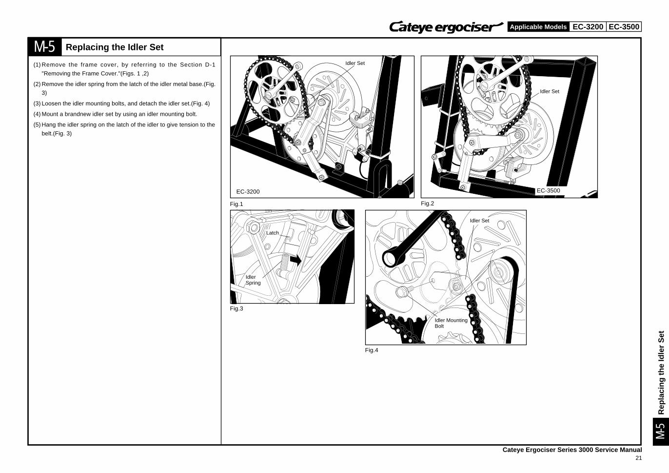
Replacing the Idler Set
(1) Remove the frame cover, by referring to the Section D-1
"Removing the Frame Cover."(Figs. 1 ,2)
(2) Remove the idler spring from the latch of the idler metal base.(Fig.
3)
(3) Loosen the idler mounting bolts, and detach the idler set.(Fig. 4)
(4) Mount a brandnew idler set by using an idler mounting bolt.
(5) Hang the idler spring on the latch of the idler to give tension to the
belt.(Fig. 3)
Idler Set
Idler Set
Latch
Idler Set
Idler MountingBolt
Rep
laci
ng th
e Id
ler
Set
EC-3200 EC-3500
Cateye Ergociser Series 3000 Service Manual22
Applicable Models
M-6
M-6
Fig.1 Fig.2
Fig.3 Fig.4 Fig.5
Fig.6 Fig.7 Fig.8
CoinCrankCap
EC-3200
CrankSet
Pulley "B"Shaft
Cotterless Removing/Fastening Tool
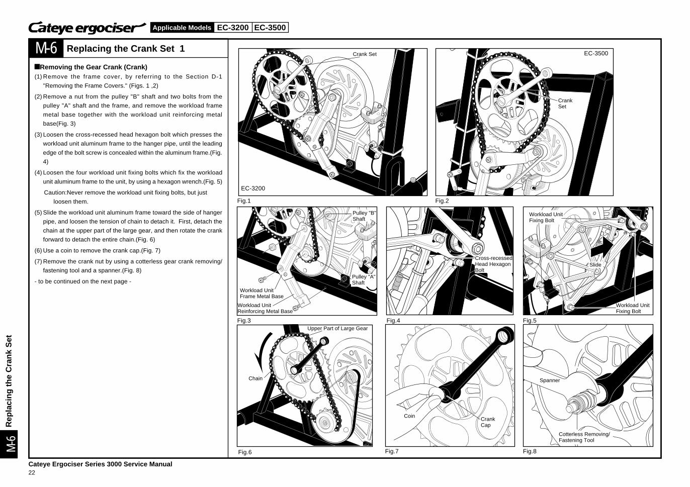
Replacing the Crank Set 1
àRemoving the Gear Crank (Crank)(1) Remove the frame cover, by referring to the Section D-1
"Removing the Frame Covers." (Figs. 1 ,2)
(2) Remove a nut from the pulley "B" shaft and two bolts from the
pulley "A" shaft and the frame, and remove the workload frame
metal base together with the workload unit reinforcing metal
base(Fig. 3)
(3) Loosen the cross-recessed head hexagon bolt which presses the
workload unit aluminum frame to the hanger pipe, until the leading
edge of the bolt screw is concealed within the aluminum frame.(Fig.
4)
(4) Loosen the four workload unit fixing bolts which fix the workload
unit aluminum frame to the unit, by using a hexagon wrench.(Fig. 5)
Caution:Never remove the workload unit fixing bolts, but just
loosen them.
(5) Slide the workload unit aluminum frame toward the side of hanger
pipe, and loosen the tension of chain to detach it. First, detach the
chain at the upper part of the large gear, and then rotate the crank
forward to detach the entire chain.(Fig. 6)
(6) Use a coin to remove the crank cap.(Fig. 7)
(7) Remove the crank nut by using a cotterless gear crank removing/
fastening tool and a spanner.(Fig. 8)
- to be continued on the next page -
Crank Set EC-3500
Pulley "A"Shaft
Workload UnitFrame Metal Base
Workload UnitReinforcing Metal Base
Cross-recessedHead HexagonBolt
Slide
Workload UnitFixing Bolt
Workload UnitFixing Bolt
Chain
Upper Part of Large Gear
Spanner
Rep
laci
ng th
e C
rank
Set
EC-3200 EC-3500
Cateye Ergociser Series 3000 Service Manual23
Applicable Models
M-6
M-6
Fig.9 Fig.10
Fig.11
Cotterless Removing/Fastening Tool
Spanner
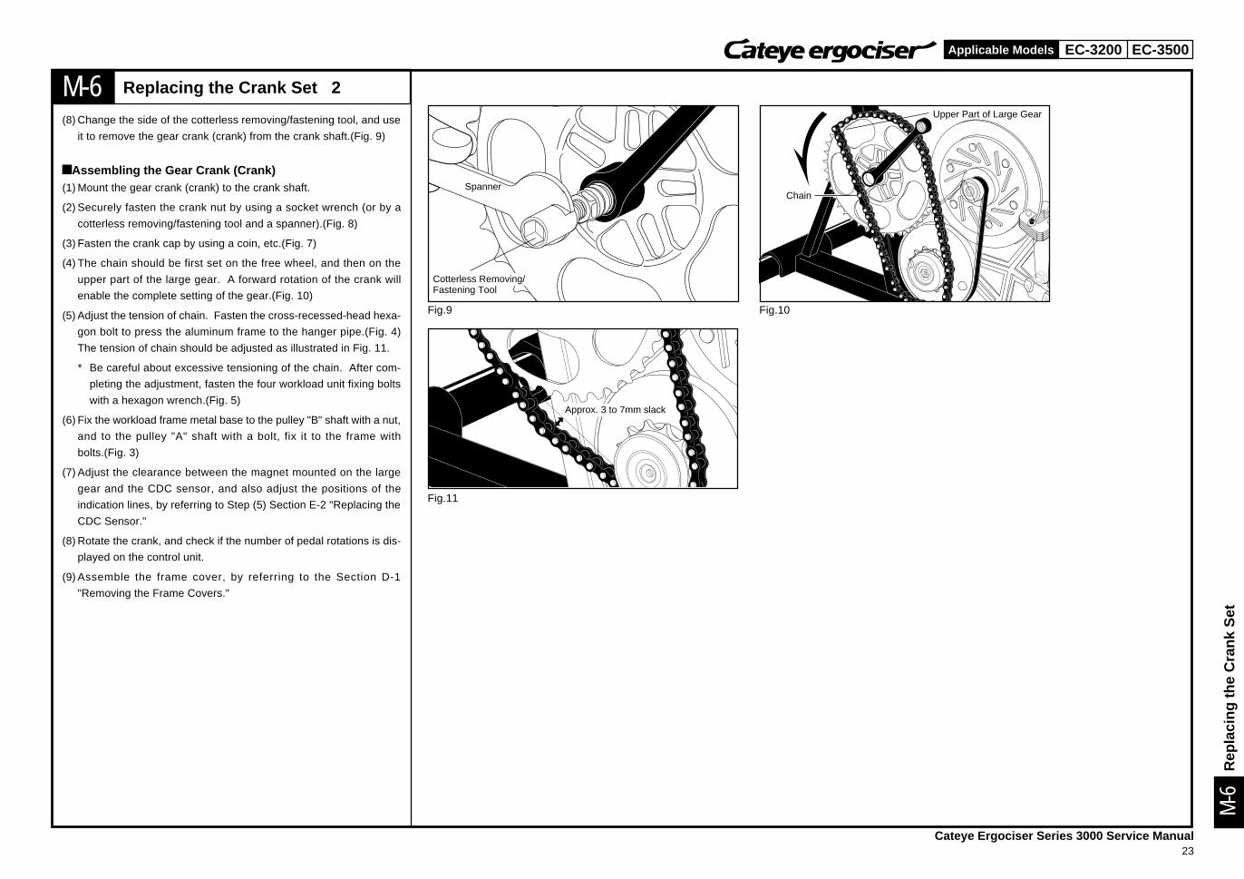
Replacing the Crank Set 2
(8) Change the side of the cotterless removing/fastening tool, and use
it to remove the gear crank (crank) from the crank shaft.(Fig. 9)
àAssembling the Gear Crank (Crank)(1) Mount the gear crank (crank) to the crank shaft.
(2) Securely fasten the crank nut by using a socket wrench (or by a
cotterless removing/fastening tool and a spanner).(Fig. 8)
(3) Fasten the crank cap by using a coin, etc.(Fig. 7)
(4) The chain should be first set on the free wheel, and then on the
upper part of the large gear. A forward rotation of the crank will
enable the complete setting of the gear.(Fig. 10)
(5) Adjust the tension of chain. Fasten the cross-recessed-head hexa-
gon bolt to press the aluminum frame to the hanger pipe.(Fig. 4)
The tension of chain should be adjusted as illustrated in Fig. 11.
* Be careful about excessive tensioning of the chain. After com-
pleting the adjustment, fasten the four workload unit fixing bolts
with a hexagon wrench.(Fig. 5)
(6) Fix the workload frame metal base to the pulley "B" shaft with a nut,
and to the pulley "A" shaft with a bolt, fix it to the frame with
bolts.(Fig. 3)
(7) Adjust the clearance between the magnet mounted on the large
gear and the CDC sensor, and also adjust the positions of the
indication lines, by referring to Step (5) Section E-2 "Replacing the
CDC Sensor."
(8) Rotate the crank, and check if the number of pedal rotations is dis-
played on the control unit.
(9) Assemble the frame cover, by referring to the Section D-1
"Removing the Frame Covers."
Chain
Upper Part of Large Gear
Approx. 3 to 7mm slack
Rep
laci
ng th
e C
rank
Set
EC-3200 EC-3500
Cateye Ergociser Series 3000 Service Manual24
Applicable Models
M-7
M-7
Fig.1 Fig.2
Fig.3 Fig.4 Fig.5
Fig.6 Fig.7 Fig.8
BB Set
CDC SensorMetal Base
CrankShaft(BB axle)
BB adjustingcup
EC-3200
EC-3500
BB Set
BBadjustingcup
Line
CDC Magnet Approx. 2mm Clearance betweenCDC Sensor and Magnet
CDC Sensor
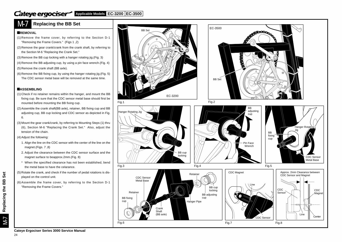
Replacing the BB Set
àREMOVAL(1) Remove the frame cover, by referring to the Section D-1
"Removing the Frame Covers." (Figs 1 ,2)
(2) Remove the gear crank/crank from the crank shaft, by referring to
the Section M-6 "Replacing the Crank Set."
(3) Remove the BB cup locking with a hanger rotating jig.(Fig. 3)
(4) Remove the BB adjusting cup, by using a pin face wrench.(Fig. 4)
(5) Remove the crank shaft (BB axle).
(6) Remove the BB fixing cup, by using the hanger rotating jig.(Fig. 5)
The CDC sensor metal base will be removed at the same time.
àASSEMBLING(1) Check if no retainer remains within the hanger, and mount the BB
fixing cup. Be sure that the CDC sensor metal base should first be
mounted before mounting the BB fixing cup.
(2) Assemble the crank shaft(BB axle), retainer, BB fixing cup and BB
adjusting cup, BB cup locking and CDC sensor as depicted in Fig.
6.
(3) Mount the gear crank/crank, by referring to Mounting Steps (1) thru
(6), Section M-6 "Replacing the Crank Set." Also, adjust the
tension of the chain.
(4) Adjust the following:
1. Align the line on the CDC sensor with the center of the line on the
magnet.(Figs. 7 ,8)
2. Adjust the clearance between the CDC sensor surface and the
magnet surface to beapprox.2mm.(Fig. 8)
* When the specified clearance has not been established, bend
the metal base to have the celarance.
(5) Rotate the crank, and check if the number of pedal rotations is dis-
played on the control unit.
(6) Assemble the frame cover, by referring to the Section D-1
"Removing the Frame Covers."
Hanger Rotating Jig
Pin FaceWrench
Hanger RotatingJig
CDC SensorMetal Base
Retainer
Hanger Pipe
Retainer
LineCenter
CDCMagnet
CDCSensor
Rep
laci
ng th
e B
B S
et
BB fixingcup
BBfixingcup
BB cuplocking
BB cuplocking
EC-3200 EC-3500
Cateye Ergociser Series 3000 Service Manual25
Applicable Models
M-8
M-8
Fig.1 Fig.2
EC-3500EC-3200
Fig.3
Magnet
Fig.4
Magnet
Fig.5
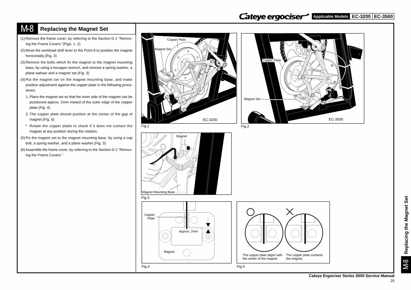
Replacing the Magnet Set
(1) Remove the frame cover, by referring to the Section D-1 "Remov-
ing the Frame Covers."(Figs. 1 ,2)
(2) Move the workload shift lever to the Point 8 to position the magnet
horizontally.(Fig. 3)
(3) Remove the bolts which fix the magnet to the magnet mounting
base, by using a hexagon wrench, and remove a spring washer, a
plane wahser and a magnet set.(Fig. 3)
(4) Put the magnet set on the magnet mounting base, and make
position adjustment against the copper plate in the following proce-
dures:
1. Place the magnet set so that the inner side of the magnet can be
positioned approx. 2mm inward of the outer edge of the copper
plate.(Fig. 4)
2. The copper plate should position at the center of the gap of
magnet.(Fig. 5)
* Rotate the copper plalte to check if it does not contact the
magnet at any position during the rotation.
(5) Fix the magnet set to the magnet mounting base, by using a cap
bolt, a spring washer, and a plane washer.(Fig. 3)
(6) Assemble the frame cover, by referring to the Section D-1 "Remov-
ing the Frame Covers."
Magnet Set
Magnet Mounting Base
Copper Plate
Magnet Set
CopperPlate
Approx. 2mm
Copper Plate
The copper plate contactsthe magnet.
The copper plate aligns withthe center of the magnet.
Rep
laci
ng th
e M
agne
t Set
EC-3200 EC-3500
Cateye Ergociser Series 3000 Service Manual26
Applicable Models
M-9
Fig.1 Fig.2
Fig.3 Fig.4
Workload Shift Lever
Joint Bar
MagnetMounting Base
EC-3500
MagnetMounting Base
WorkloadShift Lever
Joint Bar
Joint Bar
EC-3200
M-9
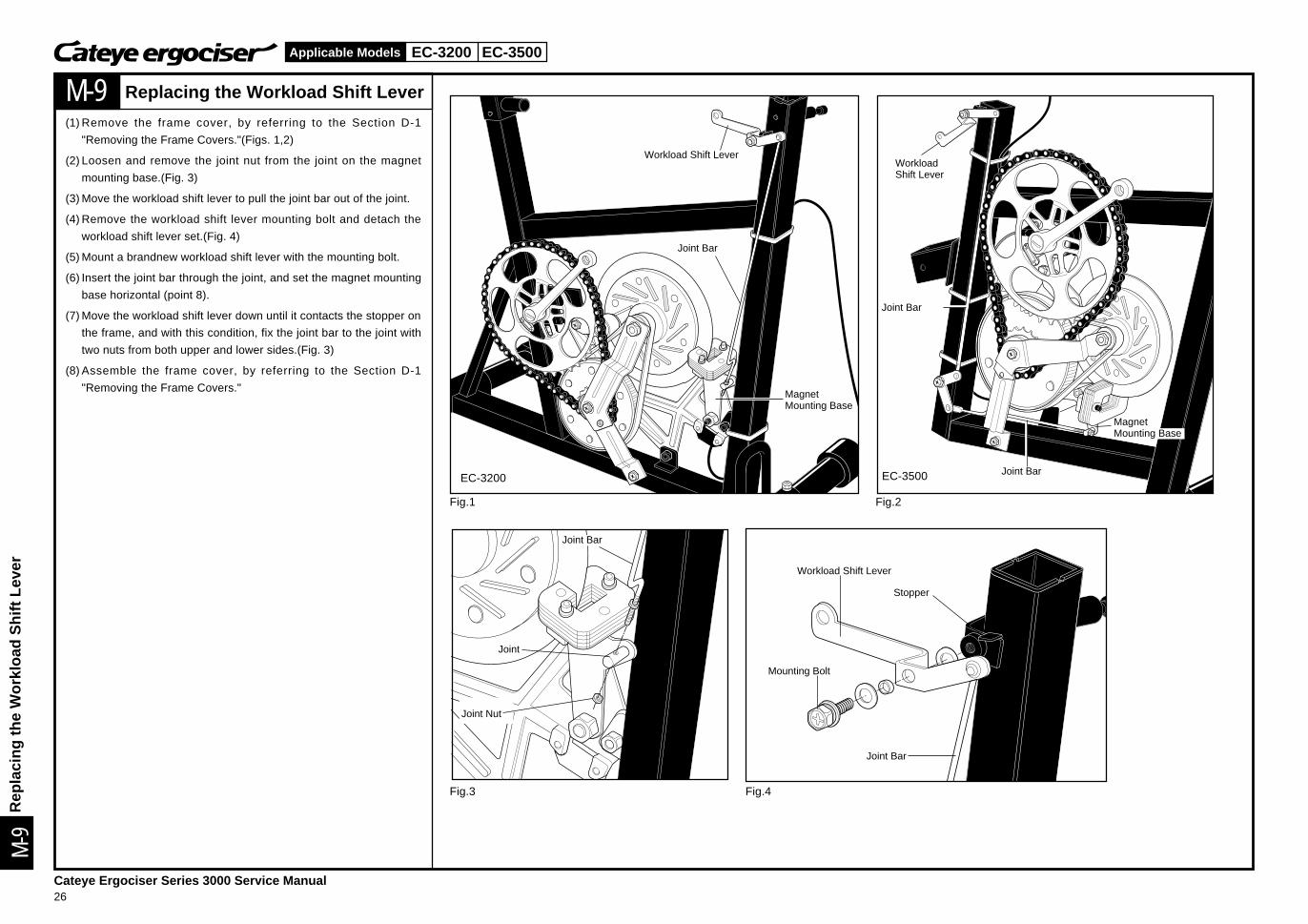
Replacing the Workload Shift Lever
(1) Remove the frame cover, by referring to the Section D-1
"Removing the Frame Covers."(Figs. 1,2)
(2) Loosen and remove the joint nut from the joint on the magnet
mounting base.(Fig. 3)
(3) Move the workload shift lever to pull the joint bar out of the joint.
(4) Remove the workload shift lever mounting bolt and detach the
workload shift lever set.(Fig. 4)
(5) Mount a brandnew workload shift lever with the mounting bolt.
(6) Insert the joint bar through the joint, and set the magnet mounting
base horizontal (point 8).
(7) Move the workload shift lever down until it contacts the stopper on
the frame, and with this condition, fix the joint bar to the joint with
two nuts from both upper and lower sides.(Fig. 3)
(8) Assemble the frame cover, by referring to the Section D-1
"Removing the Frame Covers."
Joint Bar
Joint Nut
Joint
Workload Shift Lever
Mounting Bolt
Stopper
Joint Bar
Rep
laci
ng th
e W
orkl
oad
Shi
ft Le
ver
EC-3200
Cateye Ergociser Series 3000 Service Manual27
Applicable Models
M-10
M-1
0
Fig.1 Fig.2
Fig.3
Boss
Press in
Post Spacer
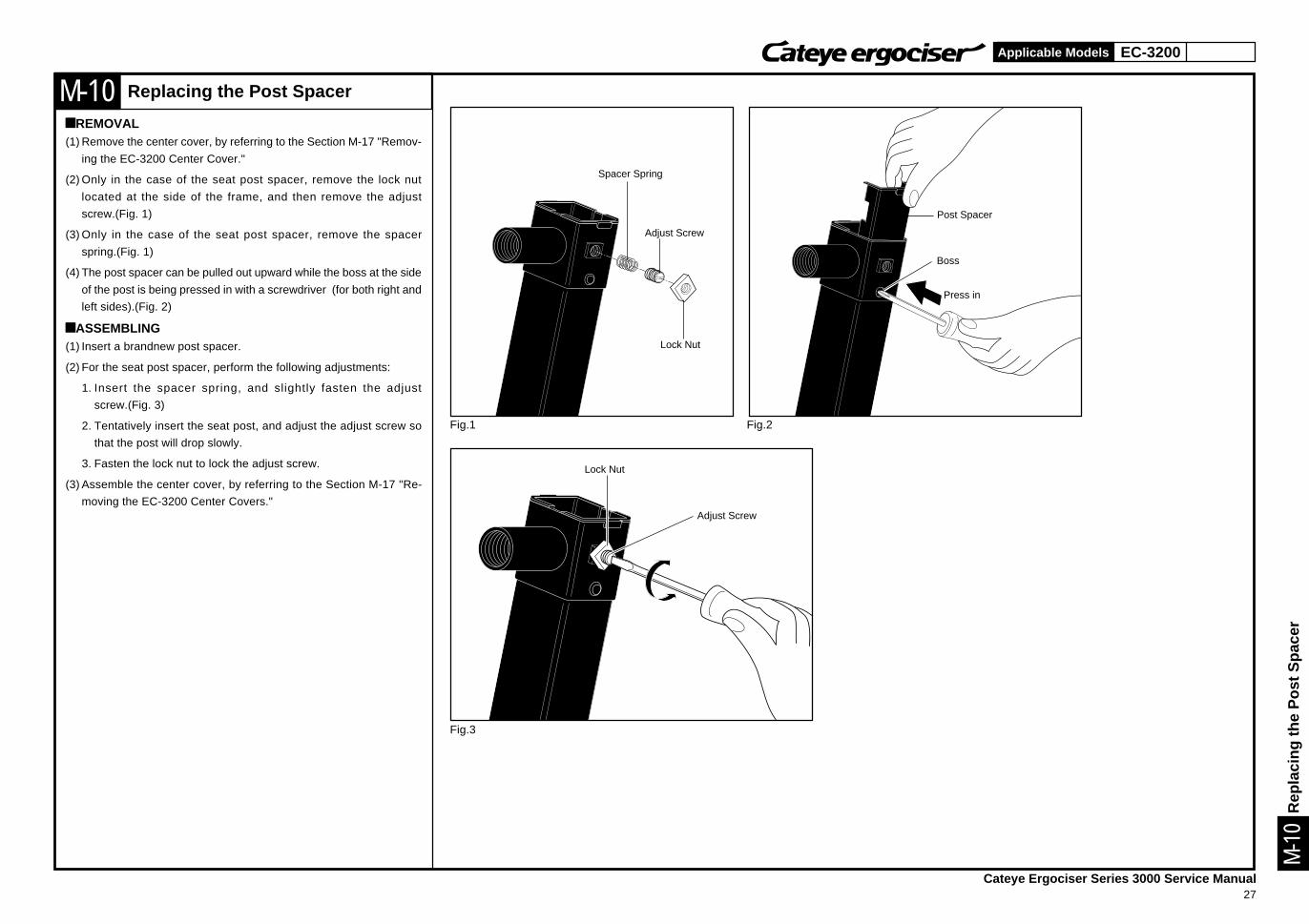
Replacing the Post Spacer
àREMOVAL(1) Remove the center cover, by referring to the Section M-17 "Remov-
ing the EC-3200 Center Cover."
(2) Only in the case of the seat post spacer, remove the lock nut
located at the side of the frame, and then remove the adjust
screw.(Fig. 1)
(3) Only in the case of the seat post spacer, remove the spacer
spring.(Fig. 1)
(4) The post spacer can be pulled out upward while the boss at the side
of the post is being pressed in with a screwdriver (for both right and
left sides).(Fig. 2)
àASSEMBLING(1) Insert a brandnew post spacer.
(2) For the seat post spacer, perform the following adjustments:
1. Insert the spacer spring, and slightly fasten the adjust
screw.(Fig. 3)
2. Tentatively insert the seat post, and adjust the adjust screw so
that the post will drop slowly.
3. Fasten the lock nut to lock the adjust screw.
(3) Assemble the center cover, by referring to the Section M-17 "Re-
moving the EC-3200 Center Covers."
Adjust Screw
Lock Nut
Spacer Spring
Adjust Screw
Lock Nut
Rep
laci
ng th
e P
ost S
pace
r
EC-3200
Cateye Ergociser Series 3000 Service Manual28
Applicable Models
M-11
Fig.1
Adjust Screw
Lock Nut
M-1
1
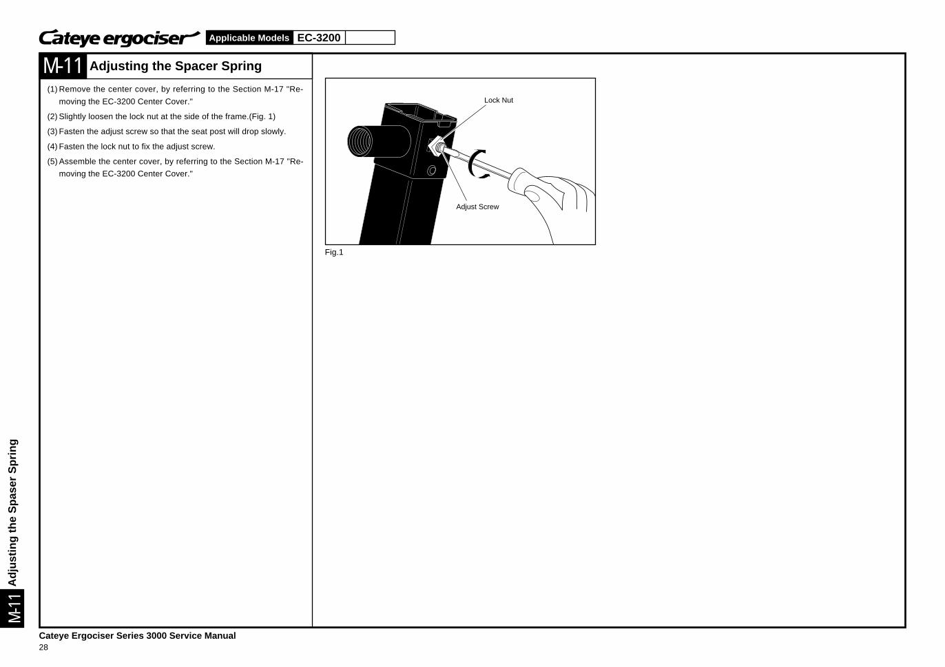
Adjusting the Spacer Spring
(1) Remove the center cover, by referring to the Section M-17 "Re-
moving the EC-3200 Center Cover."
(2) Slightly loosen the lock nut at the side of the frame.(Fig. 1)
(3) Fasten the adjust screw so that the seat post will drop slowly.
(4) Fasten the lock nut to fix the adjust screw.
(5) Assemble the center cover, by referring to the Section M-17 "Re-
moving the EC-3200 Center Cover."
Adj
ustin
g th
e S
pase
r S
prin
g
EC-3500
Cateye Ergociser Series 3000 Service Manual29
Applicable Models
M-12
Fig.1 Fig.2
M-1
2
Fig.3 Fig.4
Stopper Screw
Seat Pipe
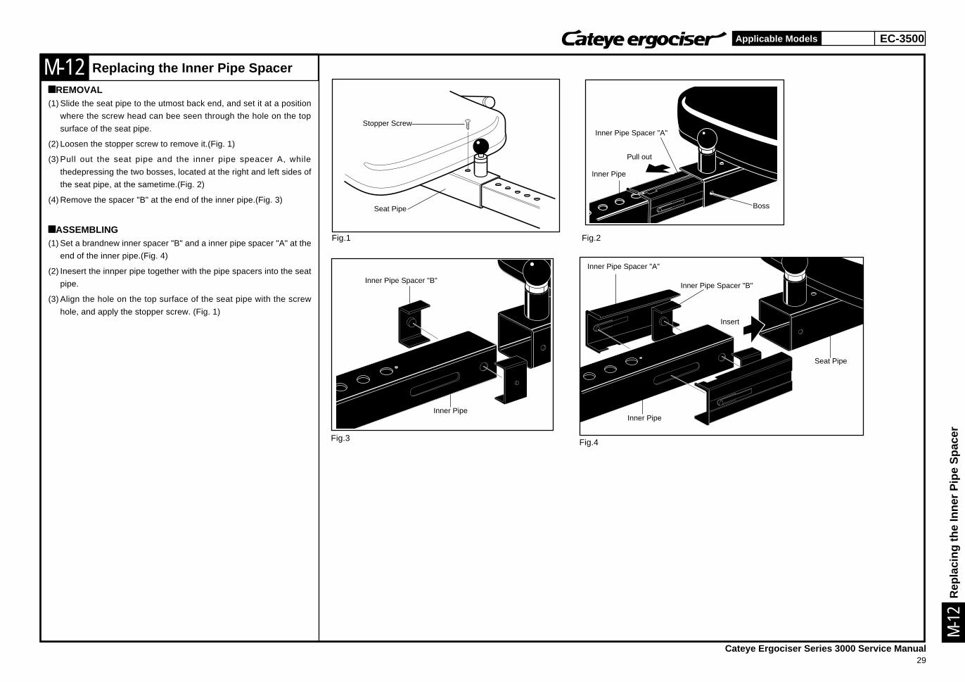
Replacing the Inner Pipe Spacer
àREMOVAL(1) Slide the seat pipe to the utmost back end, and set it at a position
where the screw head can bee seen through the hole on the top
surface of the seat pipe.
(2) Loosen the stopper screw to remove it.(Fig. 1)
(3) Pull out the seat pipe and the inner pipe speacer A, while
thedepressing the two bosses, located at the right and left sides of
the seat pipe, at the sametime.(Fig. 2)
(4) Remove the spacer "B" at the end of the inner pipe.(Fig. 3)
àASSEMBLING(1) Set a brandnew inner spacer "B" and a inner pipe spacer "A" at the
end of the inner pipe.(Fig. 4)
(2) Inesert the innper pipe together with the pipe spacers into the seat
pipe.
(3) Align the hole on the top surface of the seat pipe with the screw
hole, and apply the stopper screw. (Fig. 1)
Inner Pipe
Inner Pipe Spacer "A"
Inner Pipe Spacer "B"
Pull out
Inner Pipe
Inner Pipe Spacer "A"
Insert
Inner Pipe
Seat Pipe
Boss
Rep
laci
ng th
e In
ner
Pip
e S
pace
r
Inner Pipe Spacer "B"
EC-3500
Cateye Ergociser Series 3000 Service Manual30
Applicable Models
M-13
Fig.1
Fig.1
Seat Hite Lock Knob
M-1
3
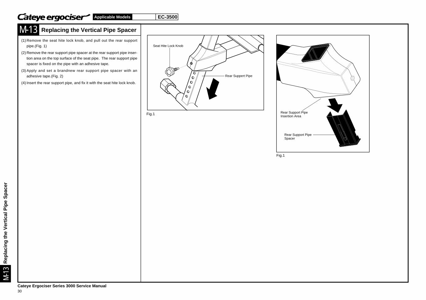
Replacing the Vertical Pipe Spacer
(1) Remove the seat hite lock knob, and pull out the rear support
pipe.(Fig. 1)
(2) Remove the rear support pipe spacer at the rear support pipe inser-
tion area on the top surface of the seat pipe. The rear support pipe
spacer is fixed on the pipe with an adhesive tape.
(3) Apply and set a brandnew rear support pipe spacer with an
adhesive tape.(Fig. 2)
(4) Insert the rear support pipe, and fix it with the seat hite lock knob.
Rear Suppert Pipe
Rear Support PipeInsertion Area
Rear Support PipeSpacer
Rep
laci
ng th
e V
ertic
al P
ipe
Spa
cer
EC-3200
Cateye Ergociser Series 3000 Service Manual31
Applicable Models
M-14
Fig.1
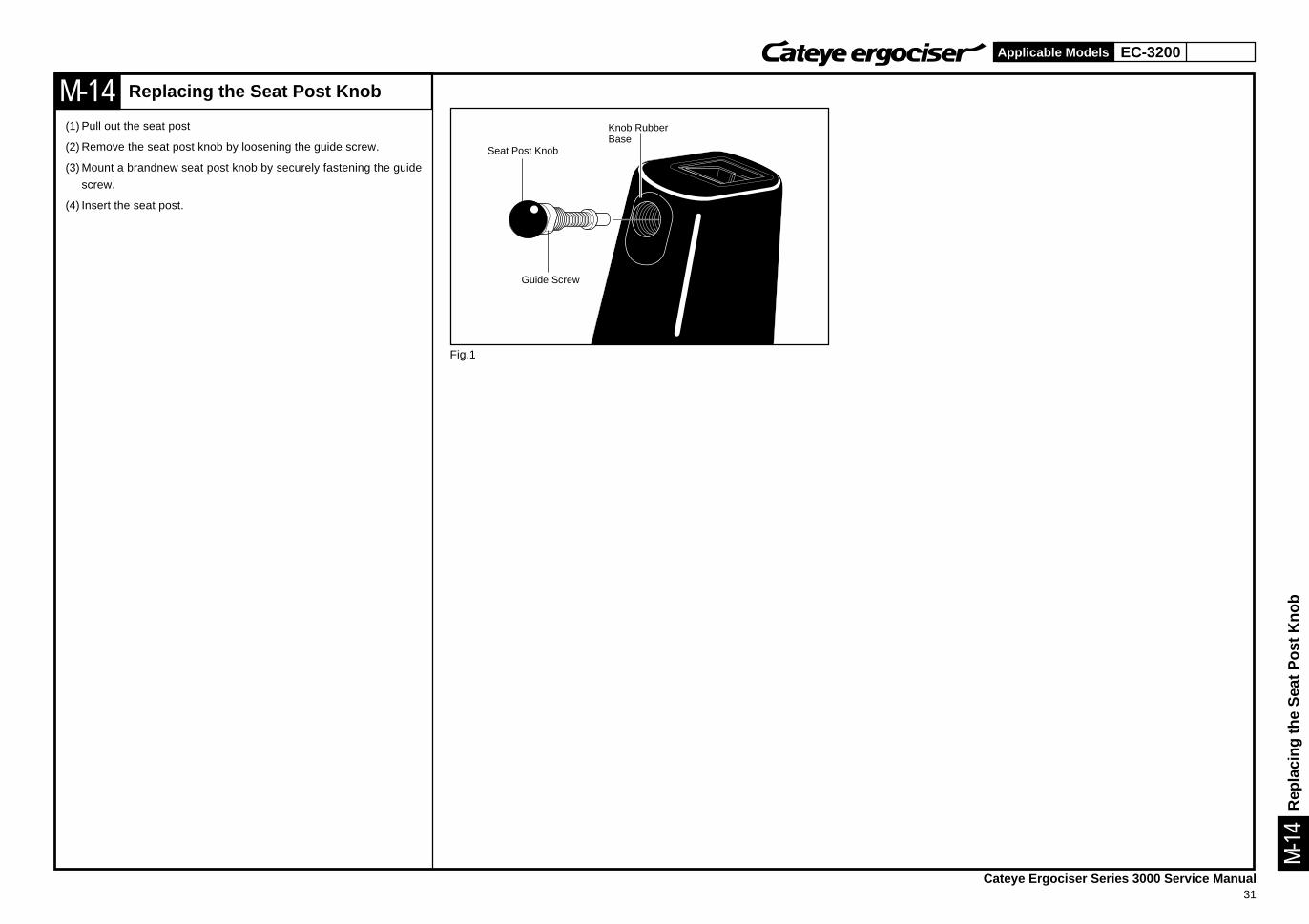
Replacing the Seat Post Knob
(1) Pull out the seat post
(2) Remove the seat post knob by loosening the guide screw.
(3) Mount a brandnew seat post knob by securely fastening the guide
screw.
(4) Insert the seat post.
Knob RubberBase
Seat Post Knob
Guide Screw
Rep
laci
ng th
e S
eat P
ost K
nob
M-1
4
EC-3500
Cateye Ergociser Series 3000 Service Manual32
Applicable Models
M-15
Fig.1
M-1
5
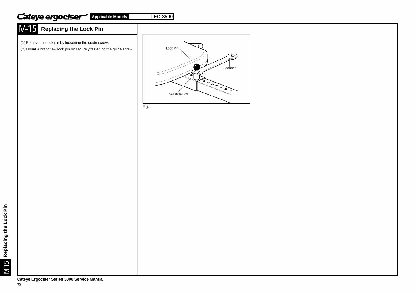
Replacing the Lock Pin
(1) Remove the lock pin by loosening the guide screw.
(2) Mount a brandnew lock pin by securely fastening the guide screw. Lock Pin
Spanner
Guide Screw
Rep
laci
ng th
e Lo
ck P
in
EC-3200 EC-3500
Cateye Ergociser Series 3000 Service Manual33
Applicable Models
M-16
Fig.1 Fig.2
M-1
6
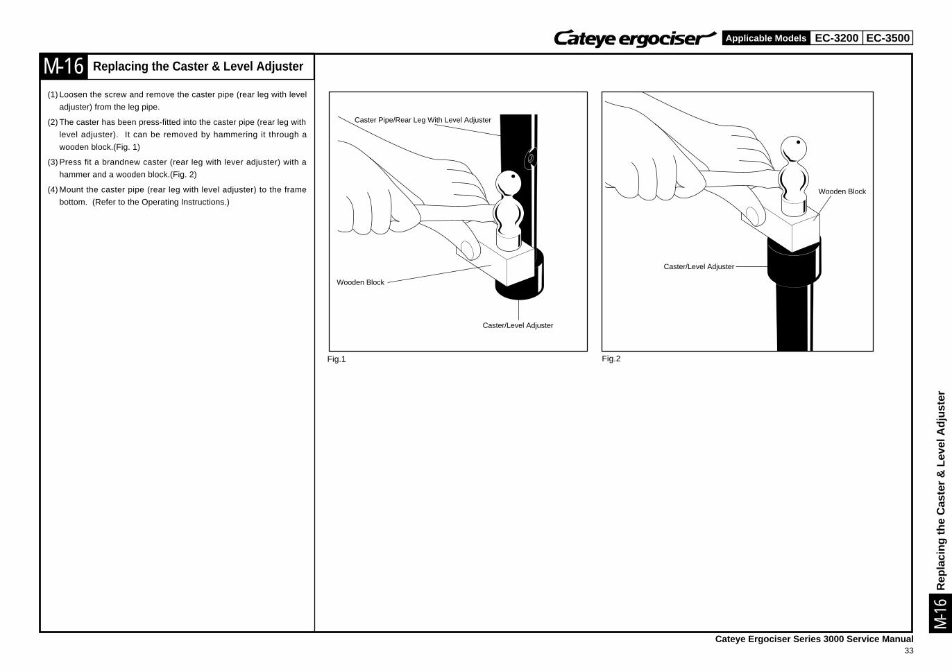
Replacing the Caster & Level Adjuster
(1) Loosen the screw and remove the caster pipe (rear leg with level
adjuster) from the leg pipe.
(2) The caster has been press-fitted into the caster pipe (rear leg with
level adjuster). It can be removed by hammering it through a
wooden block.(Fig. 1)
(3) Press fit a brandnew caster (rear leg with lever adjuster) with a
hammer and a wooden block.(Fig. 2)
(4) Mount the caster pipe (rear leg with level adjuster) to the frame
bottom. (Refer to the Operating Instructions.)
Caster Pipe/Rear Leg With Level Adjuster
Caster/Level Adjuster
Wooden Block
Caster/Level Adjuster
Wooden Block
Rep
laci
ng th
e C
aste
r &
Lev
el A
djus
ter
EC-3200
Cateye Ergociser Series 3000 Service Manual34
Applicable Models
M-17
Fig.1 Fig.2
Fig.3
Fig.4 Fig.5
Fig.6 Fig.7
Cable Connector
Seat PostKnob
Guide Screw
Workload Shift Knob
Center CoverFixing Screw
Screw
Handlebar Post
Seat PostSeat Post Knob
Center CoverFixing Screw
Center CoverFixing Screw
M-1
7
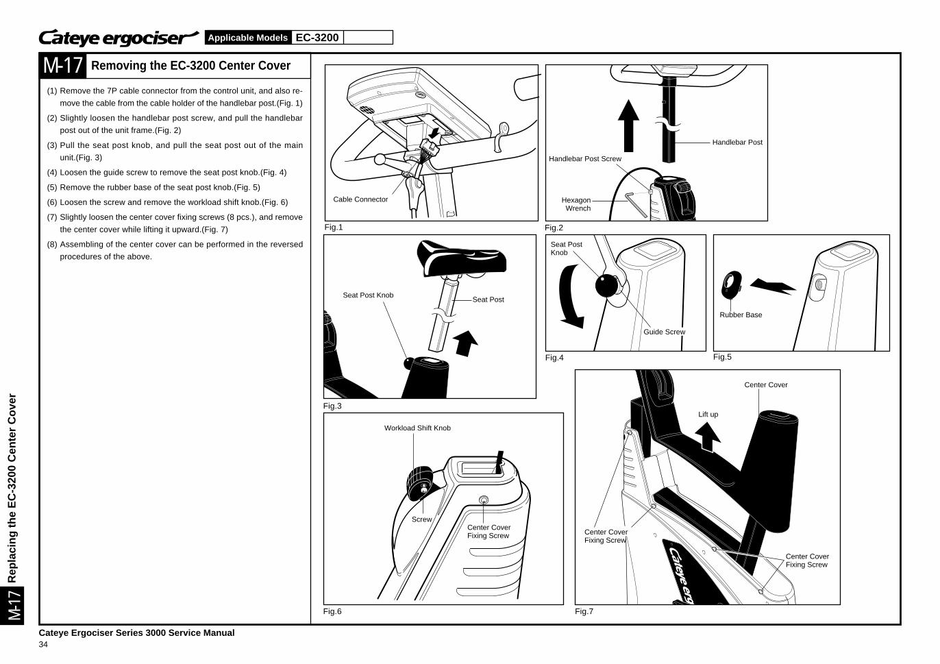
Removing the EC-3200 Center Cover
(1) Remove the 7P cable connector from the control unit, and also re-
move the cable from the cable holder of the handlebar post.(Fig. 1)
(2) Slightly loosen the handlebar post screw, and pull the handlebar
post out of the unit frame.(Fig. 2)
(3) Pull the seat post knob, and pull the seat post out of the main
unit.(Fig. 3)
(4) Loosen the guide screw to remove the seat post knob.(Fig. 4)
(5) Remove the rubber base of the seat post knob.(Fig. 5)
(6) Loosen the screw and remove the workload shift knob.(Fig. 6)
(7) Slightly loosen the center cover fixing screws (8 pcs.), and remove
the center cover while lifting it upward.(Fig. 7)
(8) Assembling of the center cover can be performed in the reversed
procedures of the above.
Handlebar Post Screw
HexagonWrench
Rubber Base
Center Cover
Lift up
Rep
laci
ng th
e E
C-3
200
Cen
ter
Cov
er
EC-3500
Cateye Ergociser Series 3000 Service Manual35
Applicable Models
EC-35OO
M-18
Fig.1 Fig.2
Fig.3 Fig.4
Fig.5 Fig.6
Joint Fitting
Center Cover
M-1
8
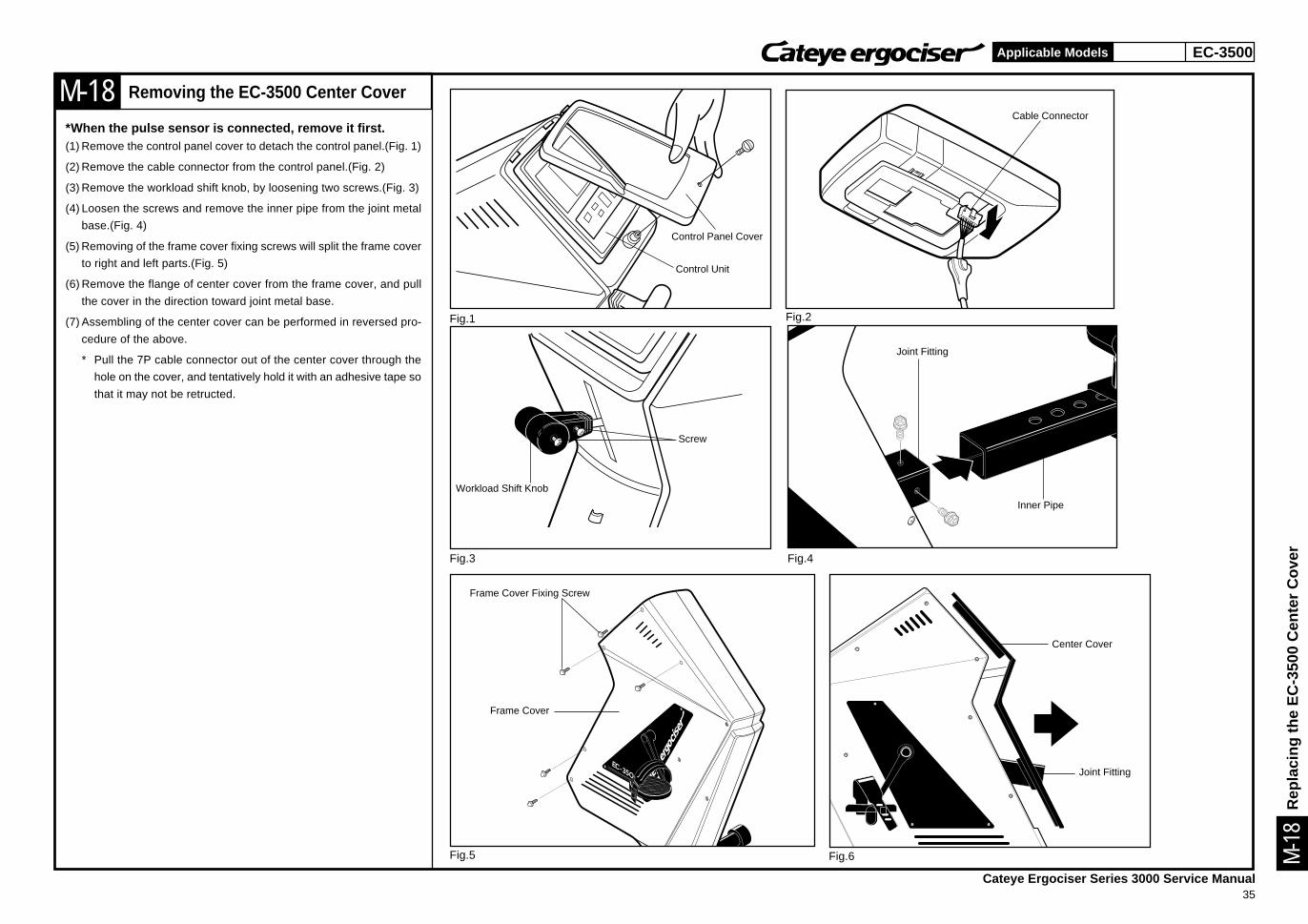
Removing the EC-3500 Center Cover
*When the pulse sensor is connected, remove it first.(1) Remove the control panel cover to detach the control panel.(Fig. 1)
(2) Remove the cable connector from the control panel.(Fig. 2)
(3) Remove the workload shift knob, by loosening two screws.(Fig. 3)
(4) Loosen the screws and remove the inner pipe from the joint metal
base.(Fig. 4)
(5) Removing of the frame cover fixing screws will split the frame cover
to right and left parts.(Fig. 5)
(6) Remove the flange of center cover from the frame cover, and pull
the cover in the direction toward joint metal base.
(7) Assembling of the center cover can be performed in reversed pro-
cedure of the above.
* Pull the 7P cable connector out of the center cover through the
hole on the cover, and tentatively hold it with an adhesive tape so
that it may not be retructed.
Control Panel Cover
Control Unit
Cable Connector
Workload Shift Knob
Screw
Joint Fitting
Inner Pipe
Frame Cover
Frame Cover Fixing Screw
Rep
laci
ng th
e E
C-3
500
Cen
ter
Cov
er
EC-3200 EC-3500
Cateye Ergociser Series 3000 Service Manual36
Applicable Models
M-19
Fig.1 Fig.2
Existing Grip (Old)
M-1
9
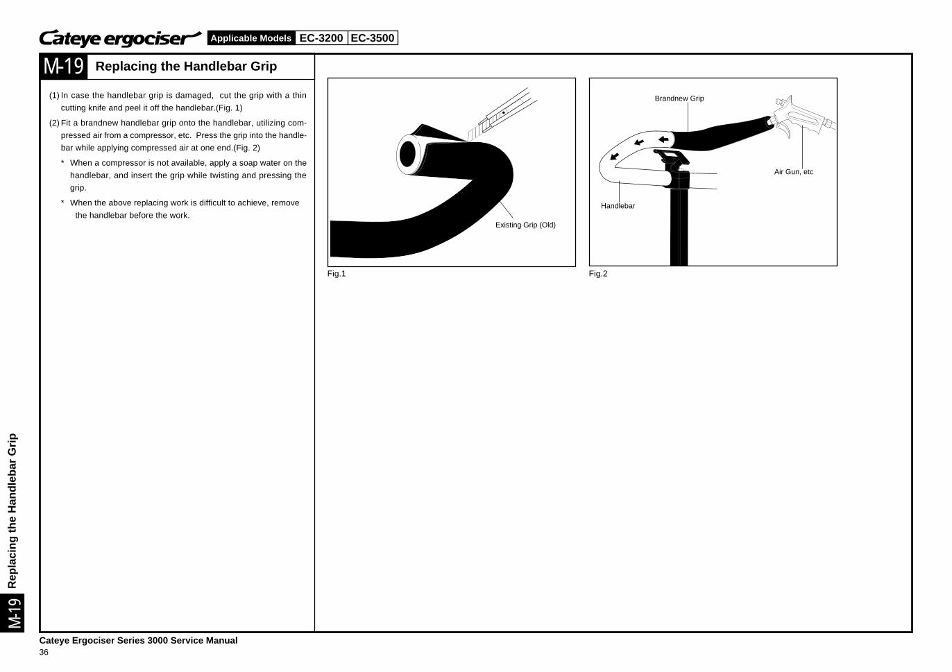
Replacing the Handlebar Grip
(1) In case the handlebar grip is damaged, cut the grip with a thin
cutting knife and peel it off the handlebar.(Fig. 1)
(2) Fit a brandnew handlebar grip onto the handlebar, utilizing com-
pressed air from a compressor, etc. Press the grip into the handle-
bar while applying compressed air at one end.(Fig. 2)
* When a compressor is not available, apply a soap water on the
handlebar, and insert the grip while twisting and pressing the
grip.
* When the above replacing work is difficult to achieve, remove
the handlebar before the work.Handlebar
Air Gun, etc
Brandnew Grip
Rep
laci
ng th
e H
andl
ebar
Grip
EC-3200 EC-3500Applicable Models
Lis
t of G
enu
in P
arts
Cateye Ergociser Series 3000 Service Manual37
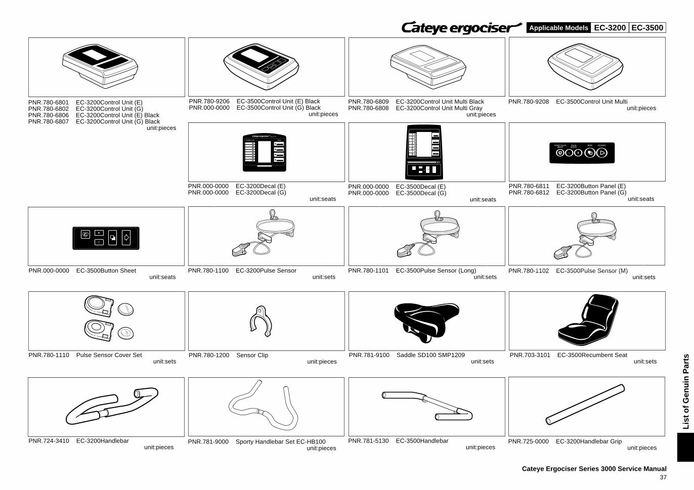
TARGET PULSEON/OFF
VALUEADJUST
MODE ADVANCE
PNR.780-6801 EC-3200Control Unit (E)PNR.780-6802 EC-3200Control Unit (G)PNR.780-6806 EC-3200Control Unit (E) BlackPNR.780-6807 EC-3200Control Unit (G) Black
unit:pieces
PNR.780-9206 EC-3500Control Unit (E) BlackPNR.000-0000 EC-3500Control Unit (G) Black
unit:pieces
PNR.780-9208 EC-3500Control Unit Multiunit:pieces
PNR.000-0000 EC-3200Decal (E)PNR.000-0000 EC-3200Decal (G)
unit:seats
PNR.000-0000 EC-3500Decal (E)PNR.000-0000 EC-3500Decal (G)
unit:seats
PNR.780-6811 EC-3200Button Panel (E)PNR.780-6812 EC-3200Button Panel (G)
unit:seats
PNR.000-0000 EC-3500Button Sheetunit:seats
PNR.780-1100 EC-3200Pulse Sensorunit:sets
PNR.780-1101 EC-3500Pulse Sensor (Long)unit:sets
PNR.780-1102 EC-3500Pulse Sensor (M)unit:sets
PNR.780-1110 Pulse Sensor Cover Setunit:sets
PNR.780-1200 Sensor Clipunit:pieces
PNR.781-9100 Saddle SD100 SMP1209unit:sets
PNR.703-3101 EC-3500Recumbent Seatunit:sets
PNR.724-3410 EC-3200Handlebarunit:pieces
PNR.781-9000 Sporty Handlebar Set EC-HB100unit:pieces
PNR.781-5130 EC-3500Handlebarunit:pieces
PNR.725-0000 EC-3200Handlebar Gripunit:pieces
EC-3200
PNR.780-6809 EC-3200Control Unit Multi BlackPNR.780-6808 EC-3200Control Unit Multi Gray
unit:pieces
EC-3200 EC-3500Applicable Models
Lis
t of G
enu
in P
arts
Cateye Ergociser Series 3000 Service Manual38
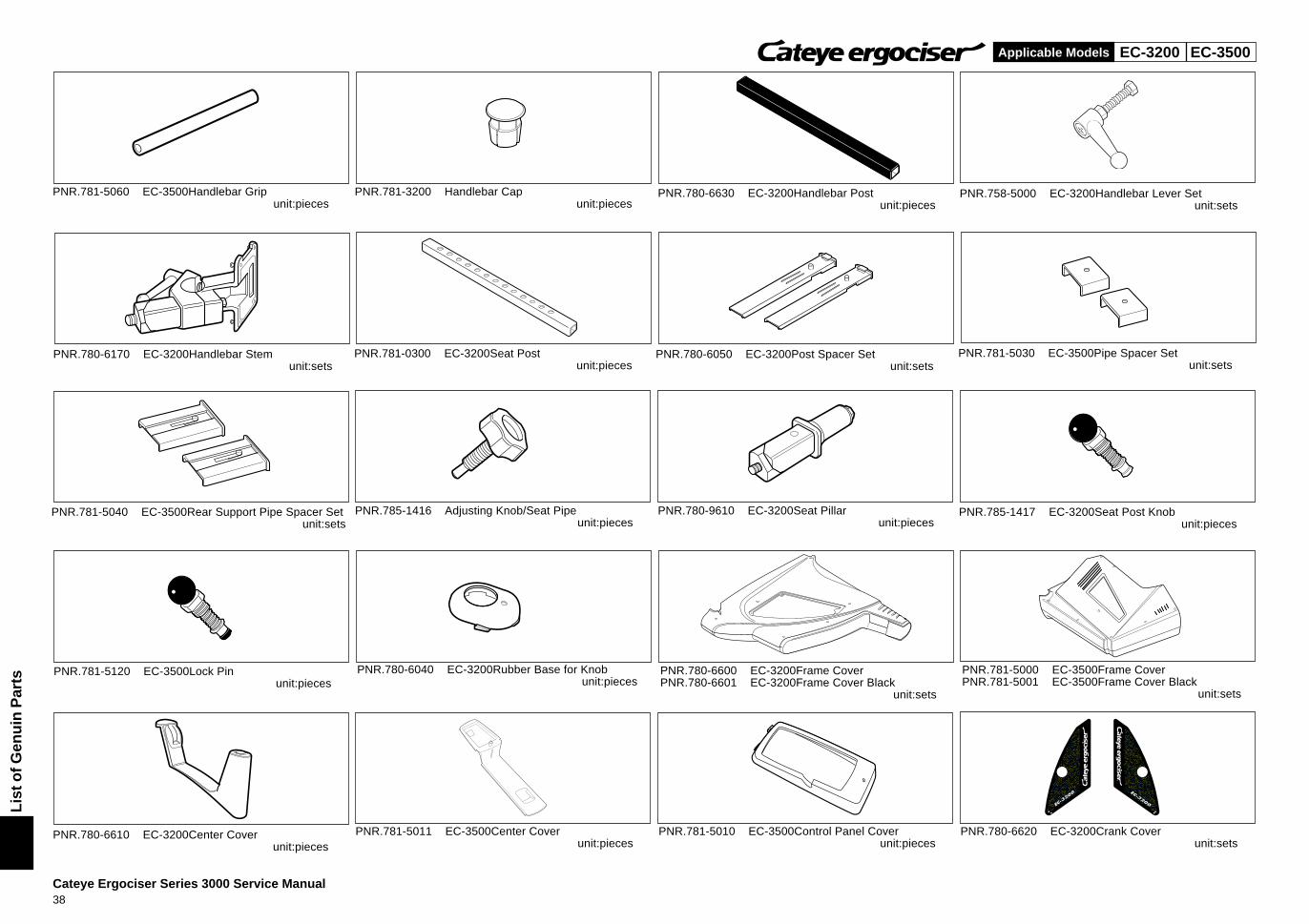
PNR.781-3200 Handlebar Capunit:pieces
®
®
PNR.780-6630 EC-3200Handlebar Postunit:pieces
PNR.758-5000 EC-3200Handlebar Lever Setunit:sets
PNR.780-6170 EC-3200Handlebar Stemunit:sets
PNR.781-0300 EC-3200Seat Postunit:pieces
PNR.780-6050 EC-3200Post Spacer Setunit:sets
PNR.781-5030 EC-3500Pipe Spacer Setunit:sets
PNR.781-5040 EC-3500Rear Support Pipe Spacer Setunit:sets
PNR.785-1416 Adjusting Knob/Seat Pipeunit:pieces
PNR.780-9610 EC-3200Seat Pillarunit:pieces
PNR.785-1417 EC-3200Seat Post Knobunit:pieces
PNR.781-5120 EC-3500Lock Pinunit:pieces
PNR.780-6040 EC-3200Rubber Base for Knobunit:pieces
PNR.780-6600 EC-3200Frame CoverPNR.780-6601 EC-3200Frame Cover Black
unit:sets
PNR.781-5000 EC-3500Frame CoverPNR.781-5001 EC-3500Frame Cover Black
unit:sets
PNR.780-6610 EC-3200Center Coverunit:pieces
PNR.781-5011 EC-3500Center Coverunit:pieces
PNR.781-5010 EC-3500Control Panel Coverunit:pieces
PNR.780-6620 EC-3200Crank Coverunit:sets
PNR.781-5060 EC-3500Handlebar Gripunit:pieces
EC-3200 EC-3500Applicable Models
Lis
t of G
enu
in P
arts
Cateye Ergociser Series 3000 Service Manual39
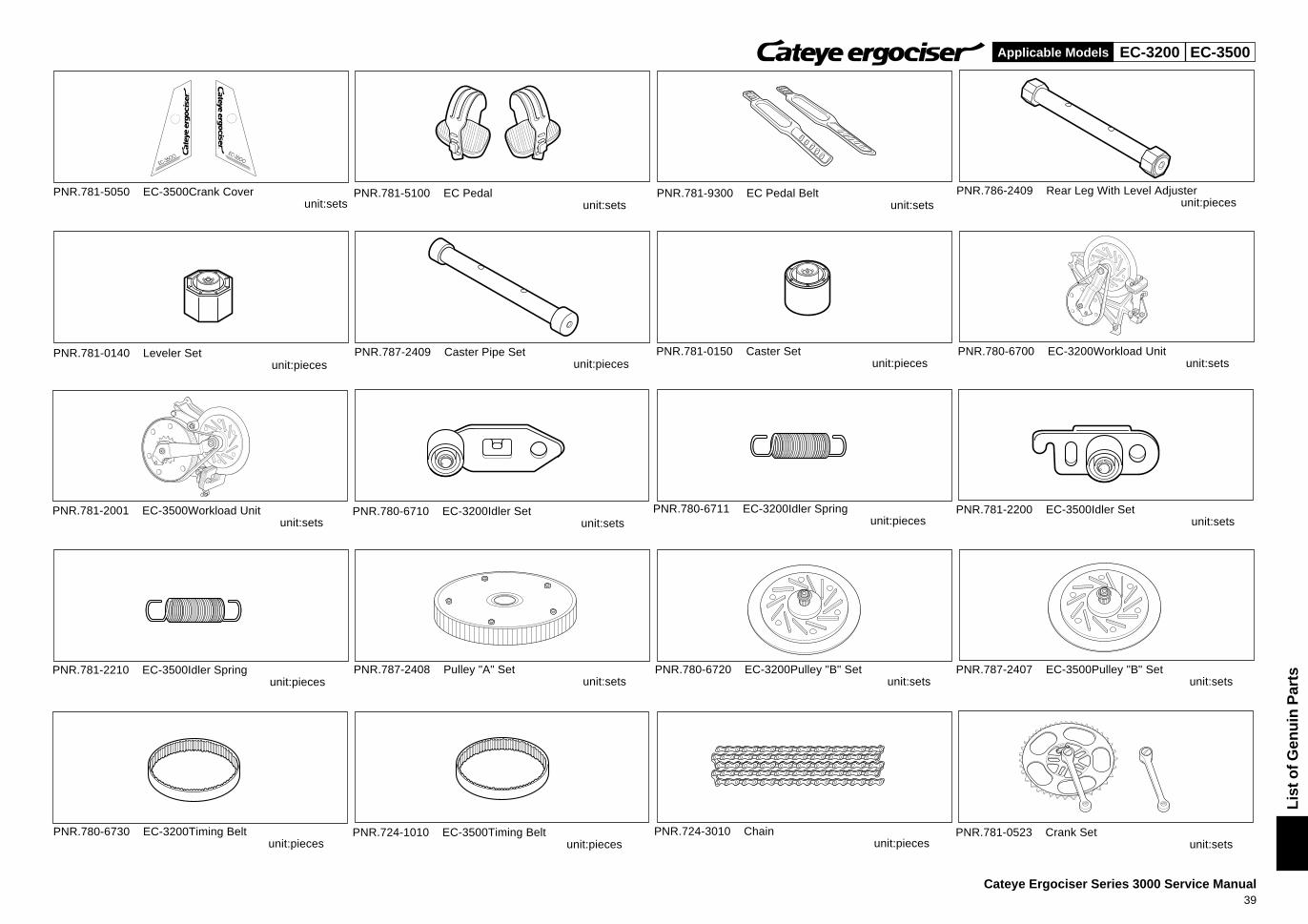
PNR.781-5100 EC Pedalunit:sets
R
R
PNR.781-5050 EC-3500Crank Coverunit:sets
PNR.781-9300 EC Pedal Beltunit:sets
PNR.786-2409 Rear Leg With Level Adjusterunit:pieces
PNR.781-0140 Leveler Setunit:pieces
PNR.787-2409 Caster Pipe Setunit:pieces
PNR.781-0150 Caster Setunit:pieces
PNR.780-6700 EC-3200Workload Unitunit:sets
PNR.781-2001 EC-3500Workload Unitunit:sets
PNR.780-6710 EC-3200Idler Setunit:sets
PNR.780-6711 EC-3200Idler Springunit:pieces
PNR.781-2200 EC-3500Idler Setunit:sets
PNR.781-2210 EC-3500Idler Springunit:pieces
PNR.787-2408 Pulley "A" Setunit:sets
PNR.780-6720 EC-3200Pulley "B" Setunit:sets
PNR.787-2407 EC-3500Pulley "B" Setunit:sets
PNR.780-6730 EC-3200Timing Beltunit:pieces
PNR.724-1010 EC-3500Timing Beltunit:pieces
PNR.724-3010 Chainunit:pieces
PNR.781-0523 Crank Setunit:sets
EC-3200 EC-3500Applicable Models
Lis
t of G
enu
in P
arts
Cateye Ergociser Series 3000 Service Manual40
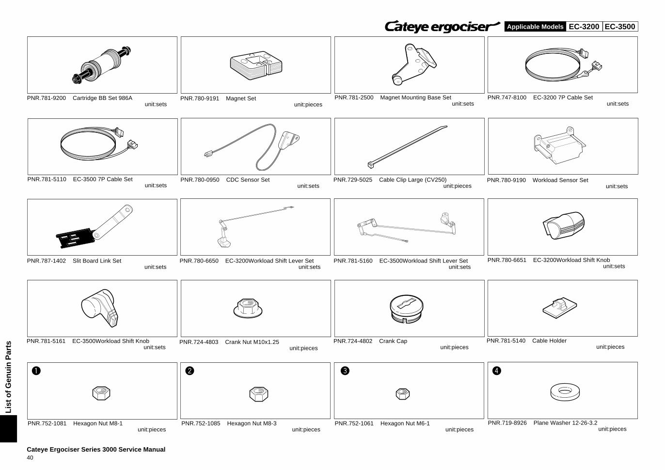
PNR.780-9191 Magnet Setunit:pieces
PNR.781-2500 Magnet Mounting Base Setunit:sets
PNR.747-8100 EC-3200 7P Cable Setunit:sets
PNR.781-5110 EC-3500 7P Cable Setunit:sets
PNR.780-0950 CDC Sensor Setunit:sets
PNR.729-5025 Cable Clip Large (CV250)unit:pieces
PNR.780-9190 Workload Sensor Setunit:sets
PNR.787-1402 Slit Board Link Setunit:sets
PNR.780-6650 EC-3200Workload Shift Lever Setunit:sets
PNR.781-5160 EC-3500Workload Shift Lever Setunit:sets
PNR.780-6651 EC-3200Workload Shift Knobunit:sets
PNR.781-5161 EC-3500Workload Shift Knobunit:sets
PNR.724-4803 Crank Nut M10x1.25unit:pieces
PNR.724-4802 Crank Capunit:pieces
PNR.781-5140 Cable Holderunit:pieces
PNR.752-1081 Hexagon Nut M8-1unit:pieces
PNR.752-1085 Hexagon Nut M8-3unit:pieces
PNR.752-1061 Hexagon Nut M6-1unit:pieces
PNR.719-8926 Plane Washer 12-26-3.2unit:pieces
1 2 3 4
PNR.781-9200 Cartridge BB Set 986Aunit:sets
EC-3200 EC-3500Applicable Models
Lis
t of G
enu
in P
arts
Cateye Ergociser Series 3000 Service Manual41
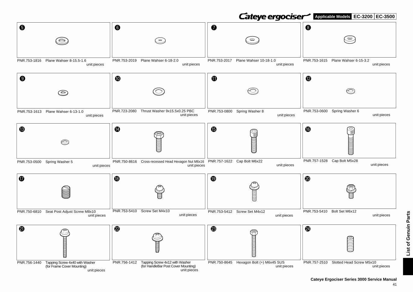
PNR.753-1816 Plane Wahser 8-15.5-1.6unit:pieces
PNR.753-2019 Plane Wahser 6-18-2.0unit:pieces
PNR.753-2017 Plane Wahser 10-18-1.0unit:pieces
PNR.753-1615 Plane Wahser 6-15-3.2unit:pieces
PNR.753-1613 Plane Wahser 6-13-1.0unit:pieces
PNR.723-2080 Thrust Washer 9x15.5x0.25 PBCunit:pieces
PNR.753-0800 Spring Washer 8unit:pieces
PNR.753-0600 Spring Washer 6unit:pieces
PNR.753-0500 Spring Washer 5unit:pieces
PNR.750-8616 Cross-recessed Head Hexagon Nut M6x16unit:pieces
PNR.757-1622 Cap Bolt M6x22unit:pieces
PNR.757-1528 Cap Bolt M5x28unit:pieces
PNR.750-6810 Seat Post Adjust Screw M8x10unit:pieces
PNR.753-5410 Screw Set M4x10unit:pieces
PNR.753-5412 Screw Set M4x12unit:pieces
PNR.753-5410 Bolt Set M6x12unit:pieces
PNR.756-1440 Tapping Screw 4x40 with Washer(for Frame Cover Mounting)
unit:pieces
PNR.756-1412 Tapping Screw 4x12 with Washer(for HandleBar Post Cover Mounting)
unit:pieces
PNR.750-8645 Hexagon Bolt (+) M6x45 SUSunit:pieces
PNR.757-2510 Slotted Head Screw M5x10unit:pieces
5 6 7 8
9 0 q w
e r t y
u i o p
a s d f
EC-3200 EC-3500Applicable Models
Lis
t of G
enu
in P
arts
Cateye Ergociser Series 3000 Service Manual42
R
EC-3200
®
MODEL EC-35OO
R
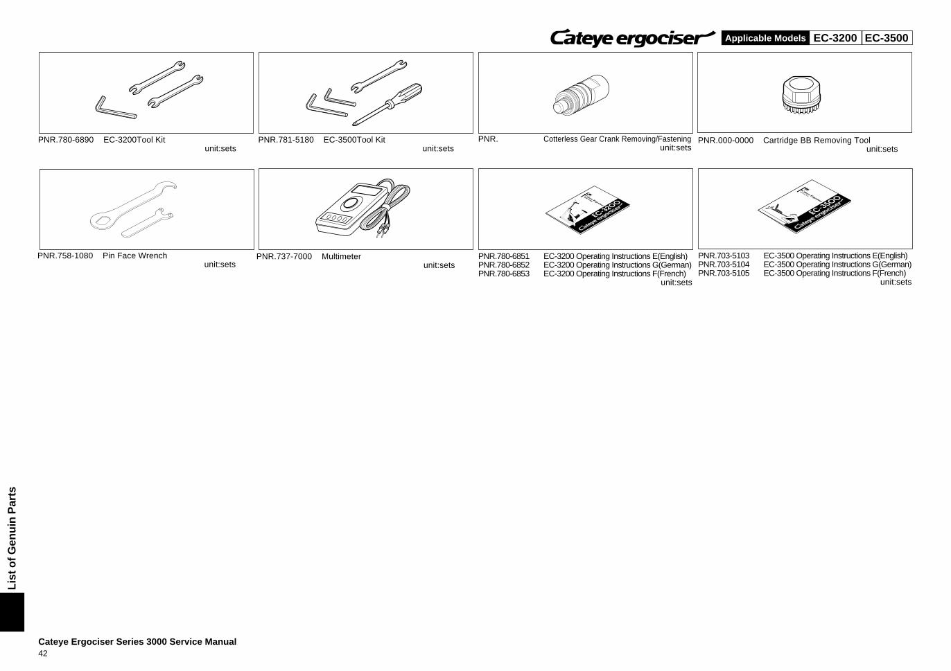
PNR.780-6890 EC-3200Tool Kitunit:sets
PNR.781-5180 EC-3500Tool Kitunit:sets
PNR. Cotterless Gear Crank Removing/Fasteningunit:sets
PNR.000-0000 Cartridge BB Removing Toolunit:sets
PNR.758-1080 Pin Face Wrenchunit:sets
PNR.737-7000 Multimeterunit:sets
PNR.780-6851 EC-3200 Operating Instructions E(English)PNR.780-6852 EC-3200 Operating Instructions G(German)PNR.780-6853 EC-3200 Operating Instructions F(French)
unit:sets
PNR.703-5103 EC-3500 Operating Instructions E(English)PNR.703-5104 EC-3500 Operating Instructions G(German)PNR.703-5105 EC-3500 Operating Instructions F(French)
unit:sets
EC-3200BApplicable Models
Lis
t o
f G
enu
in P
arts
(B
elt
Dri
ve)
Cateye Ergociser Series 3000 Service Manual43
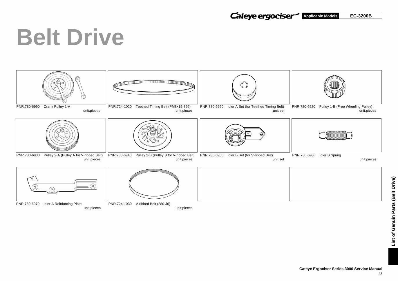
Belt Drive
PNR.780-6990 Crank Pulley 1-Aunit:pieces
PNR.724-1020 Teethed Timing Belt (PM8x15-896)unit:pieces
PNR.780-6950 Idler A Set (for Teethed Timing Belt)unit:set
PNR.780-6920 Pulley 1-B (Free Wheeling Pulley)unit:pieces
PNR.780-6930 Pulley 2-A (Pulley A for V-ribbed Belt)unit:pieces
PNR.780-6940 Pulley 2-B (Pulley B for V-ribbed Belt)unit:pieces
PNR.780-6960 Idler B Set (for V-ribbed Belt)unit:set
PNR.780-6980 Idler B Springunit:pieces
PNR.780-6970 Idler A Reinforcing Plateunit:pieces
PNR.724-1030 V-ribbed Belt (280-J6)unit:pieces
CO.,LTD.®
TEL:81-6-6719-2631 FAX:81-6-6719-2363
Copyright © Feb. 1995 CATEYE Co., Ltd.
ECSM3E-991214-pdf
2-8-25, Kuwazu, Higashi Sumiyoshi-ku, OSAKA, 546-0041 JAPAN