Embed Size (px)
Citation preview
ENG-1
ENGIntroduction
Thank you for purchasing the CATEYE V2c.The V2c is a high-performance computer for riders who wish to train extensively andanalyze their data.2.4GHz-frequency digital wireless technology, which is the same technology used forwireless LAN, is used for both the speed/cadence integrated speed sensor. This technol-ogy practically eliminates interference from external noise and cross-talk with other wire-less computer users, providing you with stress-free riding.Read this instruction manual thoroughly and understand the functions of the productbefore using it.Keep it in a safe place for future reference.
About the manualsBasic installation and operationPlease go here for installation of the unit on the bicycle, preparing the computer, and thebasic operation of the product.1. How to install the unit on your bicycle ............... See page 6-82. Preparing the computer ..................................... See page 9-143. Basic operation of the computer ........................ See page 15-16
Measurement screenPlease go here to learn how to operate the computer functions.• Measurement screen .......................................... See page 17-21
Ride data reviewPlease go here to check and manage recorded data• File view ............................................................. See page 23-26
Changing computer configurationPlease go here for changing and checking each menu items.• Changing the computer configuration ................ See page 22-33
Advanced use• Recording lap and split time data ....................... See page 19 “Lap function”• Training with target cadence zone ...................... See page 34
“Use of the target zone”
Important• Always follow the sections that are marked with “ Warning!!!”.• No part of this manual may be reproduced or transmitted without the prior written
permission of CatEye Co., Ltd.• The contents and illustrations in this manual are subject to change without notice.• If you have any questions or concerns about this manual, please contact CatEye at
www.cateye.com.
ENG-3ENG-2
ENGProper use of the CatEye V2c
Observe the following instructions for safe usage.
The meaning of icons in this manual:
Warning!!! : Sections marked with these icons are critical for safe use of the device.Be sure to follow these instructions.
Caution: Important cautionary notes on the use and operation of the V2c.
* Helpful tips are highlighted with asteriks.
Warning!!! :• Do not concentrate on the data while riding. Always be sure to ride safely.• Do not leave any battery within the reach of children, and dispose of them correctly. If
a battery is swallowed, consult a doctor immediately.
Caution:• Regularly check the positions of the magnets and the speed/cadence sensors and make
sure that they are securely mounted. Tighten it firmly if there is any looseness.• Avoid leaving the main unit / wireless sensor in direct sunlight for extended periods of time.• Do not disassemble the computer, or speed sensor.• Do not subject the computer, or speed sensor to strong impact; take care also to pre-
vent any of them from falling.• Do not use paint thinner or rubbing alcohol to clean the unit.• As a nature of liquid crystal displays, sunglasses with polarized lens may block the visibility.
2.4GHz digital wireless system2.4GHz-frequency digital communication technology, which is used for wireless LAN, isadopted for both the speed/cadence integrated type speed sensor. This technology prac-tically eliminates interference from external noise and cross-talk with other wireless com-puter users, and enables to store highly reliable data. However, in a very rare occasions,objects and places may generate strong electromagnetic waves and interference, whichmay result in incorrect measurement:• TV, PC, radios, motors/engines, or in cars and trains.• Railroad crossings and near railway tracks, around television transmitting stations and
radar bases.• Other wireless computers or digitally controlled lights.
Contents
Introduction .......................................... 1About the manuals ............................... 1Proper use of the CatEye V2c ............... 3Description of computer and its parts .... 4
Computer ......................................... 4Accessories ...................................... 4
Screen display ...................................... 5How to install the unit on your bicycle ..... 6
1. Attach the bracket to the stem orhandlebar ..................................... 6
2. Mount the speed sensor andmagnet ......................................... 7
3. Remove/Install the computer ....... 8Preparing the computer ........................ 9
Removing the insulation sheet ......... 91. Formatting/Restarting operation .... 102. Date/Clock setting ...................... 113. Tire circumference input ............. 124. Set the sensor ID ........................ 135. Selecting speed unit ................... 146. Operation test ............................. 14Sensor signal status ....................... 14
Basic operation of the computer ........ 15Functions on the measurementscreen ............................................ 15Starting/Stopping themeasurement ................................. 16Backlight ........................................ 16Resetting the measurement data .... 16Power-saving function .................... 16
Measurement screen .......................... 17Upper and middle display data ....... 17Lower display data ......................... 18Pace function ................................. 19Lap function ................................... 19Countdown distance ....................... 20Target cadence zone ....................... 21
Changing the computerconfiguration ...................................... 22
File view (FILE VIEW) ..................... 23Setting the clock/date(CLOCK.DATE) ............................... 27Wheel selection and tirecircumference (WHEEL) ................. 28Searching the sensor ID(SEnSOR-ID) .................................. 28Setting the measurement unit(UnIT) ............................................. 30Total distance manual entry(ODO InPUT) .................................. 30Setting the auto-mode(AUTO MODE) ................................ 31Setting the countdown distance(C.D.DST→→→→→) .................................. 31Setting sound (SOUnD) .................. 32Setting the target cadence zone(CDC.ZOnE) .................................... 33
Use of the target zone ........................ 34Trouble shooting ................................ 35
Trouble on display .......................... 35Trouble on operation ...................... 36
Replacing battery ............................... 37Computer ....................................... 37Speed sensor ................................. 37
Maintenance ....................................... 38Spare accessories .............................. 38Specifications ..................................... 39Registration ........................................ 40Limited warranty ................................ 40
ENG-5ENG-4
ENGScreen display
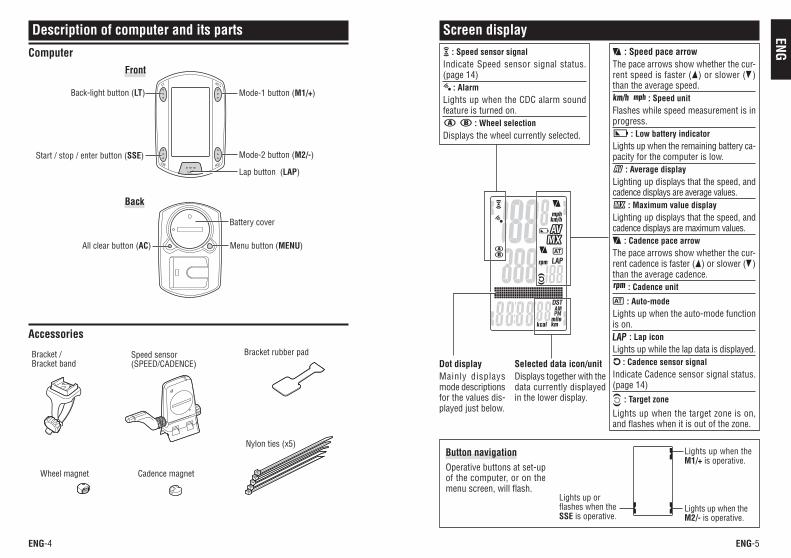
: Speed sensor signalIndicate Speed sensor signal status.(page 14)
: AlarmLights up when the CDC alarm soundfeature is turned on. : Wheel selection
Displays the wheel currently selected.
: Speed pace arrowThe pace arrows show whether the cur-rent speed is faster ( ) or slower ( )than the average speed. : Speed unit
Flashes while speed measurement is inprogress.
: Low battery indicatorLights up when the remaining battery ca-pacity for the computer is low.
: Average displayLighting up displays that the speed, andcadence displays are average values.
: Maximum value displayLighting up displays that the speed, andcadence displays are maximum values.
: Cadence pace arrowThe pace arrows show whether the cur-rent cadence is faster ( ) or slower ( )than the average cadence.
: Cadence unit
: Auto-modeLights up when the auto-mode functionis on.
: Lap iconLights up while the lap data is displayed.
: Cadence sensor signalIndicate Cadence sensor signal status.(page 14)
: Target zone
Lights up when the target zone is on,and flashes when it is out of the zone.
Dot displayMainly displaysmode descriptionsfor the values dis-played just below.
Selected data icon/unitDisplays together with thedata currently displayedin the lower display.
Button navigationOperative buttons at set-upof the computer, or on themenu screen, will flash.
Lights up orflashes when theSSE is operative.
Lights up when theM1/+ is operative.
Lights up when theM2/- is operative.
Description of computer and its parts
Computer
Accessories
Bracket /Bracket band
Speed sensor(SPEED/CADENCE)
Bracket rubber pad
Wheel magnet Cadence magnet
Nylon ties (x5)
Back-light button (LT)
Start / stop / enter button (SSE)
Mode-1 button (M1/+)
Mode-2 button (M2/-)
Menu button (MENU)
Lap button (LAP)
Battery cover
All clear button (AC)
Front
Back
ENG-7ENG-6
ENG
SPEED
CADENCE
SPEED
CADENCE
SPEED
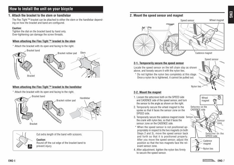
2-2. Mount the magnet
1. Loosen the setscrews both on the SPEED sideand CADENCE side of the speed sensor, and turnthe sensor to the angle as shown on the right.
2. Temporarily secure the wheel magnet to thespoke so that it faces the sensor zone on theSPEED side.
3. Temporarily secure the cadence magnet insidethe crank with nylon ties, so that it faces thesensor zone on the CADENCE side.
* When the speed sensor is not positioned ap-propriately in respect to the two magnets (in bothSteps 2 and 3), move the speed sensor backand forth so that it is positioned properly.After you move the speed sensor, adjust theposition so that the two magnets face the rel-evant sensor zone.
4. After adjustment, tighten the nylon ties firmlyto secure the speed sensor.
How to install the unit on your bicycle
When attaching the Flex Tight ™ bracket to the stem
* Attach the bracket with its open end facing to the right.
When attaching the Flex Tight ™ bracket to the handlebar
* Attach the bracket with its open end facing to the right.
Cut extra length of the band with scissors.
Caution:Round off the cut edge of the bracket band toprevent injury.
Bracket
Bracket bandBracket rubber pad Stem
Bracket
Bracket band
Bracket rubber padHandlebar
1. Attach the bracket to the stem or handlebarThe Flex Tight ™ bracket can be attached to either the stem or the handlebar depend-ing on how the bracket and band are configured.
Caution:Tighten the dial on the bracket band by hand only.Over-tightening can damage the screw threads.
2. Mount the speed sensor and magnet
2-1. Temporarily secure the speed sensorLocate the speed sensor on the left chain stay as shownabove, and loosely secure it with the nylon ties.* Do not tighten the nylon ties completely at this stage.
Once a nylon tie is tightened, it cannot be pulled out.
Wheel magnet
Cadence magnet
Speed sensor
Nylon ties
Speed sensor
Wheelmagnet
Cadencemagnet
Nylon ties
Setscrew on theCADENCE side
Sensor zoneSensorzone
Setscrew on theSPEED side
Continue
ENG-9ENG-8
ENG
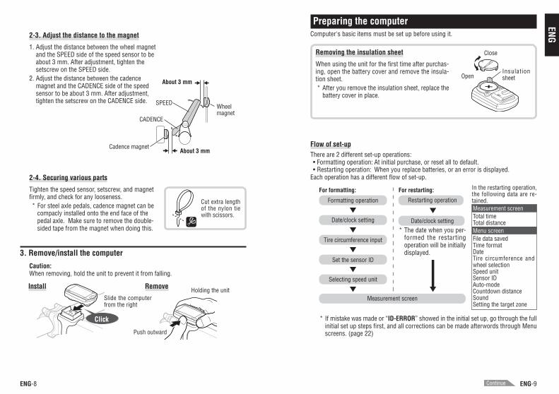
2-4. Securing various parts
Tighten the speed sensor, setscrew, and magnetfirmly, and check for any looseness.* For steel axle pedals, cadence magnet can be
compacly installed onto the end face of thepedal axle. Make sure to remove the double-sided tape from the magnet when doing this.
3. Remove/install the computer
Caution:When removing, hold the unit to prevent it from falling.
Install Remove
Click
2-3. Adjust the distance to the magnet
1. Adjust the distance between the wheel magnetand the SPEED side of the speed sensor to beabout 3 mm. After adjustment, tighten thesetscrew on the SPEED side.
2. Adjust the distance between the cadencemagnet and the CADENCE side of the speedsensor to be about 3 mm. After adjustment,tighten the setscrew on the CADENCE side.
Slide the computerfrom the right
Holding the unit
Push outward
Cut extra lengthof the nylon tiewith scissors.
Wheelmagnet
Cadence magnet
SPEED
CADENCE
About 3 mm
About 3 mm
Removing the insulation sheet
When using the unit for the first time after purchas-ing, open the battery cover and remove the insula-tion sheet.* After you remove the insulation sheet, replace the
battery cover in place.
Preparing the computerComputer's basic items must be set up before using it.
InsulationsheetOpen
Close
Measurement screen
For formatting: For restarting:
Restarting operation
* The date when you per-formed the restartingoperation will be initiallydisplayed.
Date/clock setting
In the restarting operation,the following data are re-tained.
Selecting speed unit
Set the sensor ID
Tire circumference input
Date/clock setting
Formatting operationMeasurement screenTotal timeTotal distanceMenu screenFile data savedTime formatDateTire circumference andwheel selectionSpeed unitSensor IDAuto-modeCountdown distanceSoundSetting the target zone
Flow of set-upThere are 2 different set-up operations:• Formatting operation: At initial purchase, or reset all to default.• Restarting operation: When you replace batteries, or an error is displayed.
Each operation has a different flow of set-up.
* If mistake was made or “ID-ERROR” showed in the initial set up, go through the fullinitial set up steps first, and all corrections can be made afterwords through Menuscreens. (page 22)
Continue

ENG-11ENG-10
ENG
MENU
2. Date/Clock settingSet the current date and time.
1. Select the date display format.Select the date display format from “YY/MM/DD”, “MM/DD/YY”, and “DD/MM/YY” using the M1/+ and M2/- buttons,and confirm with the SSE button.
Switch the display: M1/+M2/-
Confirm:SSE
2. Enter the “Year”, “Month” and “Day.”Enter the “Year”, “Month” and “Day” in the display orderselected in Step 1 using the M1/+ and M2/- buttons, andconfirm with the SSE button. Enter the last 2 digits of the year.
Increase/decrease: M1/+M2/-
Confirm:SSE
3. Select the clock display format.Select “24 hour” or “12 hour” using the M1/+ and M2/- buttons,and confirm with the SSE button.
24h ↔↔↔↔↔ 12h: M1/+M2/-
Confirm:SSE
4. Enter the “Hour” and “Minute.”Enter the “Hour” using the M1/+ and M2/- buttons, confirmwith the SSE button, and then enter the “Minute” in thesame way.
Increase/decrease: M1/+M2/-
Confirm:SSE
5. After you set the date/clock, press the MENU button toproceed to the next set up item.
For the formatting operation: To the “Tire circumference input” screen belowFor the restarting operation: To the measurement screen and ready for use
(or)
(or)
(Back)
(or)
Display format
Hour Minute
1. Formatting/Restarting operationFormatting operationCaution: All data are reset to the default and deleted.
1. While pressing the MENU button on the back of thecomputer, press AC button.Release the MENU button when a test pattern is displayedon the screen. The date/clock setting screen appears.Continue with date/clock setting.
Formatting operation:
* When all screen items light up without any test pattern displayed on the screen,the formatting operation has not been completed properly. Perform the formattingoperation again.
Restarting operation1. Press the AC button on the back of the computer.
After all screen items light up for a second, the date/clocksetting screen appears.Continue with date/clock setting.
Restarting operation:
* Most of the settings and file data saved are retained for the restarting operation(see chart on page 9).
After a test pattern isdisplayed, all screenitems light up.
All screen items lightup (for a second).
(At initial purchase, or reset all to default.)
(When you replace batteries, or an error is displayed.)
MENU
AC
AC
(or)
Continue
ENG-13ENG-12
ENG
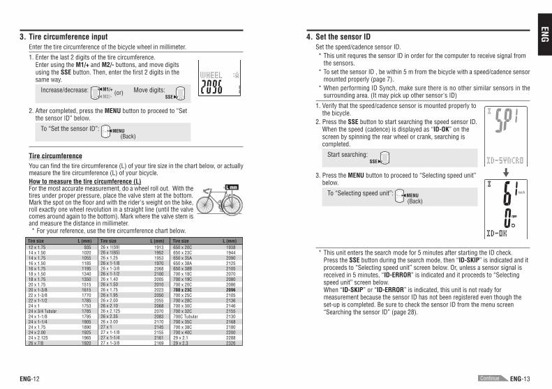
Tire size L (mm) Tire size L (mm) Tire size L (mm)12 x 1.7514 x 1.5014 x 1.7516 x 1.5016 x 1.7518 x 1.5018 x 1.7520 x 1.7520 x 1-3/822 x 1-3/822 x 1-1/224 x 124 x 3/4 Tubular24 x 1-1/824 x 1-1/424 x 1.7524 x 2.0024 x 2.12526 x 7/8
935102010551185119513401350151516151770178517531785179519051890192519651920
26 x 1(59)26 x 1(65)26 x 1.2526 x 1-1/826 x 1-3/826 x 1-1/226 x 1.4026 x 1.5026 x 1.7526 x 1.9526 x 2.0026 x 2.1026 x 2.12526 x 2.3526 x 3.0027 x 127 x 1-1/827 x 1-1/427 x 1-3/8
1913195219531970206821002005201020232050205520682070208321702145215521612169
650 x 20C650 x 23C650 x 35A650 x 38A650 x 38B700 x 18C700 x 19C700 x 20C700 x 23C700 x 25C700 x 28C700 x 30C700 x 32C700C Tubular700 x 35C700 x 38C700 x 40C29 x 2.129 x 2.3
1938194420902125210520702080208620962105213621462155213021682180220022882326
L mm
* This unit enters the search mode for 5 minutes after starting the ID check.Press the SSE button during the search mode, then “ID-SKIP” is indicated and itproceeds to “Selecting speed unit” screen below. Or, unless a sensor signal isreceived in 5 minutes, “ID-ERROR” is indicated and it proceeds to “Selectingspeed unit” screen below.When “ID-SKIP” or “ID-ERROR” is indicated, this unit is not ready formeasurement because the sensor ID has not been registered even though theset-up is completed. Be sure to check the sensor ID from the menu screen“Searching the sensor ID” (page 28).
4. Set the sensor IDSet the speed/cadence sensor ID.* This unit requres the sensor ID in order for the computer to receive signal from
the sensors.* To set the sensor ID , be within 5 m from the bicycle with a speed/cadence sensor
mounted properly (page 7).* When performing ID Synch, make sure there is no other similar sensors in the
surrounding area. (It may pick up other sensor's ID)
1. Verify that the speed/cadence sensor is mounted properly tothe bicycle.
2. Press the SSE button to start searching the speed sensor ID.When the speed (cadence) is displayed as “ID-OK” on thescreen by spinning the rear wheel or crank, searching iscompleted.
Start searching: SSE
3. Press the MENU button to proceed to “Selecting speed unit”below.
To “Selecting speed unit”: MENU(Back)
3. Tire circumference inputEnter the tire circumference of the bicycle wheel in millimeter.
1. Enter the last 2 digits of the tire circumference.Enter using the M1/+ and M2/- buttons, and move digitsusing the SSE button. Then, enter the first 2 digits in thesame way.
Increase/decrease: M1/+M2/-
Move digits:SSE
2. After completed, press the MENU button to proceed to “Setthe sensor ID” below.
To “Set the sensor ID”: MENU
Tire circumferenceYou can find the tire circumference (L) of your tire size in the chart below, or actuallymeasure the tire circumference (L) of your bicycle.How to measure the tire circumference (L)For the most accurate measurement, do a wheel roll out. With thetires under proper pressure, place the valve stem at the bottom.Mark the spot on the floor and with the rider's weight on the bike,roll exactly one wheel revolution in a straight line (until the valvecomes around again to the bottom). Mark where the valve stem isand measure the distance in millimeter.* For your reference, use the tire circumference chart below.
(or)
(Back)
Continue
ENG-15ENG-14
ENG
Average speed
Average cadence
Maximum speed
Maximum cadence
Current speed
Cadence
M1/+
M2/-M2/-
M2/-
Date
Clock
Total time
Total distance
Elapsed time Trip distanceCountdown
distance
Lapnumber
Lap timer
Averagelap
speed
Lap distance
(2 Sec.)
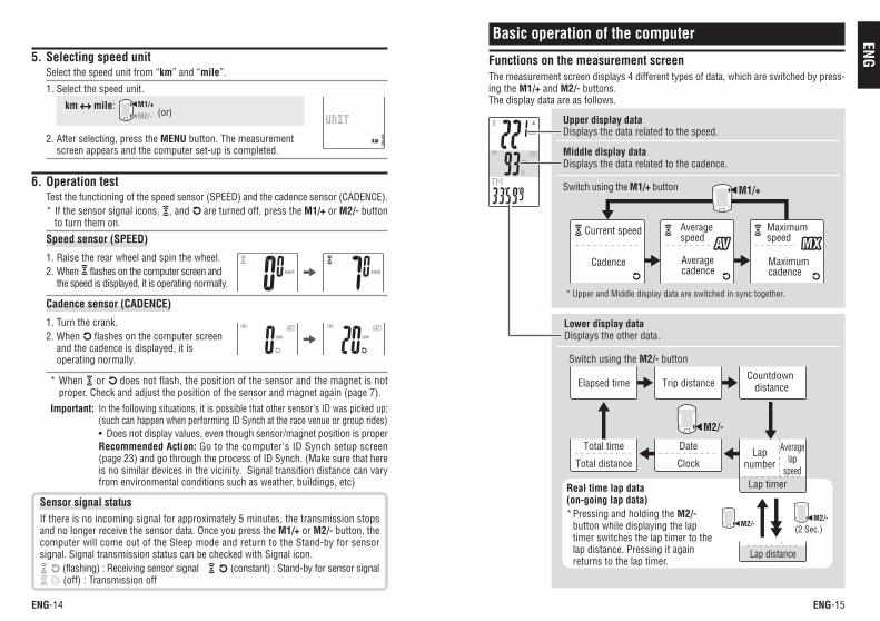
5. Selecting speed unitSelect the speed unit from “km” and “mile”.
1. Select the speed unit.
km ↔↔↔↔↔ mile: M1/+M2/-
2. After selecting, press the MENU button. The measurementscreen appears and the computer set-up is completed.
6. Operation testTest the functioning of the speed sensor (SPEED) and the cadence sensor (CADENCE).* If the sensor signal icons, , and are turned off, press the M1/+ or M2/- button
to turn them on.
Speed sensor (SPEED)
1. Raise the rear wheel and spin the wheel.2. When flashes on the computer screen and
the speed is displayed, it is operating normally.
Cadence sensor (CADENCE)
1. Turn the crank.2. When flashes on the computer screen
and the cadence is displayed, it isoperating normally.
* When or does not flash, the position of the sensor and the magnet is notproper. Check and adjust the position of the sensor and magnet again (page 7).
Important: In the following situations, it is possible that other sensor's ID was picked up;(such can happen when performing ID Synch at the race venue or group rides)• Does not display values, even though sensor/magnet position is properRecommended Action: Go to the computer's ID Synch setup screen(page 23) and go through the process of ID Synch. (Make sure that hereis no similar devices in the vicinity. Signal transition distance can varyfrom environmental conditions such as weather, buildings, etc)
Basic operation of the computer
Functions on the measurement screenThe measurement screen displays 4 different types of data, which are switched by press-ing the M1/+ and M2/- buttons.The display data are as follows.
Upper display dataDisplays the data related to the speed.
Middle display dataDisplays the data related to the cadence.
Lower display dataDisplays the other data.
Real time lap data(on-going lap data)*Pressing and holding the M2/-
button while displaying the laptimer switches the lap timer to thelap distance. Pressing it againreturns to the lap timer.
* Upper and Middle display data are switched in sync together.
Switch using the M1/+ button
Switch using the M2/- button
(or)
Sensor signal statusIf there is no incoming signal for approximately 5 minutes, the transmission stopsand no longer receive the sensor data. Once you press the M1/+ or M2/- button, thecomputer will come out of the Sleep mode and return to the Stand-by for sensorsignal. Signal transmission status can be checked with Signal icon.
(flashing) : Receiving sensor signal (constant) : Stand-by for sensor signal (off) : Transmission off
ENG-17ENG-16
ENG
1
2
3
4
5
6
M1/+
M1/+
M1/+
SSE
M1/+
SSE M2/-
LT
SSE
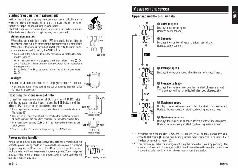
1 Current speedDisplays the current speed.Updated every second.
2 CadenceDisplays the number of pedal rotations per minute.Updated every second.
Measurement screen
Upper and middle display data
*1: When the trip distance (DST) exceeds 10,000 km [mile], or the elapsed time (TM)exceeds 100 hours, [E] appears indicating further measurement is impossible. Clearthe data by resetting (page 16).
*2: This device calculates the average excluding the time when you stop pedaling. Thisfeature produces actual averages, which are different from those with conventionalmodels that calculate it for the entire measurement time period.
3 Average speed *1
Displays the average speed after the start of measurement.
4 Average cadence *2
Displays the average cadence after the start of measurement.* The average will not be reflected when you stop pedaling.
5 Maximum speedDisplays the maximum speed after the start of measurement.Updated independently of starting/stopping measurement.
6 Maximum cadenceDisplays the maximum cadence after the start of measurement.Updated independently of starting/stopping measurement.
Starting/Stopping the measurementInitially, the unit starts or stops measurement automatically in syncwith the bicycle motion. This is called auto-mode function.“km/h” or “mph” flashes during measurement.The total distance, maximum speed, and maximum cadence are up-dated independently of stating/stopping measurement.
Auto-mode functionWhen the auto-mode is turned on ( lights up), the unit detectsthe wheel spinning, and starts/stops measurement automatically.When the auto-mode is turned off ( lights off), the unit starts/stops measurement by using the SSE button.* For on/off of the auto-mode, see the menu screen “Setting the auto-
mode” (page 31).* When the transmission is stopped and Sensor signal icons ,
are off (page 14), the main timer may not start due to speed signalnot responding.Press the M1/+ or M2/- button to turn on the sensor signal icons
, .
BacklightPressing the LT button illuminates the displays for about 3 seconds.* Pressing any button while backlight is still on extends the illumination
for another 3 seconds.
Resetting the measurement dataTo reset the measurement data (TM, DST, Lap Time, C.D. DST, etc)and the lap data, simultaneously press the SSE button and theM1/+ or M2/- button in the measurement screen.* Resetting the measurement data saves the data automatically on a
file. (page 23)* The screen will freeze for about 2 seconds after resetting; however,
all measurements are operating normally, including the elapsed time.* The countdown setting (C.D.DST→) is returned to the manu set
value you set.* Cannot reset for 5 seconds after pressing the LAP button.
Power-saving functionWhen the computer does not receive any data for 5 minutes, it willenter the power-saving mode, in which only the date/clock is displayed.By pressing any buttons except the AC recovers from the power-saving mode, and the measurement screen appears. You must pressa button when the computer is in power saving mode before it willstart to measure any data. Power-saving mode
AT icon
(or)
( S i m u l t a -neously press)
( S i m u l t a -neously press)
ENG-19ENG-18
ENG
1
2
5
3
4
6
7
8
LAP
7 98
0
q
w
e
M2/-
M2/-
M2/-
M2/-
M2/-
M2/-
M2/-
M2/-
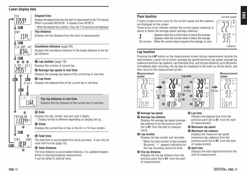
Pace function2 types of pace arrow icons for the current speed and the cadenceare displayed on the screen.These arrow icons indicate whether the current speed (cadence) isabove or below the average speed (average cadence).
: Appears when the current value is above the average.: Appears when the current value is below the average.
No arrows : When the current value is equal to the average, or zero.
Lap functionPressing the LAP button on the measurement screen during measurement records thedata between a given set of points (average lap speed/maximum lap speed, average lapcadence/maximum lap cadence, lap time/split time, and trip lap distance) up to 99 points.Immediately after recording, the lap data are displayed in the order as shown below, andthen return to the measurement screen.
Current speed
Cadence
1 Average lap speed2 Average lap cadence
Displays the average lap speed (averagelap cadence) from the previous point(for L-01: from the start of measure-ment).
3 Lap numberDisplays the lap number just recorded.*When the total number of laps exceeds
99 points, “--” appears indicating fur-ther lap recording cannot be done.
4 Trip lap distanceDisplays the trip lap distance from theprevious point (for L-01: from the startof measurement).
5 Lap timeDisplays the elapsed time from theprevious point (for L-01: from the startof measurement).
6 Maximum lap speed7 Maximum lap cadence
Displays the maximum lap speed(maximum lap cadence) from theprevious point (for L-01: from the startof measurement).
8 Split timeDisplays the total elapsed time from thestart of measurement.
Measurementscreen
MeasurementscreenLap data
2.5 sec. 2.5 sec.
Elapsed timeDisplays the elapsed time from the start of measurement to the 1/10 second.When it exceeds 99:59’59”, it repeats from 00’00”0.*When the elapsed time reaches 1 hour, the 1/10 second is not displayed.
Trip distanceDisplays the trip distance from the start of measurement.
Countdown distance (page 20)Displays the countdown distance to the target distance to the tar-get distance.
7 Lap number (page 19)Displays the number of current lap.
8 Average lap speed in real timeDisplays the average lap speed of the current lap in real time.
9 Lap timerDisplays the elapsed time of the current lap in real time.
Trip lap distance in real timeDisplays the trip distance of the current lap in real time.
0 DateDisplays the day, month, and year (last 2 digits).* Display format is different depending on display set up.
q ClockDisplays the current time of day in the 24- or 12-hour system.
w Total timeThe total time is accumulated time since purchase. It can only bereset with Format (page 10).
e Total distanceThe total distance is accumulated distance. It is updated indepen-dently of starting/stopping measurement.It can be edited to desired value.
Lower display data
(2 sec.)
Continue
ENG-21ENG-20
ENG
LAP LAPTM
Start of measurement
Lap time 1
Split time 1
Split time 2
Lap time 2
Beep
M2/-M2/-(For 2 seconds)
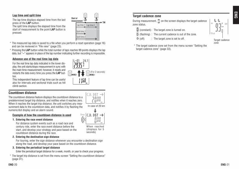
Target cadence zoneDuring measurement, on the screen displays the target cadencezone status.
(constant) : The target zone is turned on.
(flashing) : The current cadence is out of the zone. (off) : The target zone is set to off.
* The target cadence zone set from the menu screen “Setting thetarget cadence zone” (page 33).
Target cadencezone
Lap time and split timeThe lap time displays elapsed time from the lastpress of the LAP button.The split time displays the elapsed time from thestart of measurement to the point LAP button ispressed.
* The measured lap data is saved to a file when you perform a reset operation (page 16)and can be reviewed in “File view” (page 23).
* Pressing the LAP button while the total number of laps reaches 99 points displays the lapdata, but “--” appears in place of the lap number indicating further recording is impossible.
Advance use of the real time lap dataFor the real time lap data indicated in the lower dis-play, the unit starts/stops measurement in sync withthe main time measurement; however, it resets andrestarts the data every time you press the LAP but-ton.This independent feature of lap time can be usefulalso for intervals and sectional trials such as hillclimb section.
Countdown distanceThe countdown distance feature displays the countdown distance to apredetermined target trip distance, and notifies when it reaches zero.When it reaches the target trip distance, the unit switches any mea-surement data to the countdown data, and notifies it by flashing thenumeric/dot display and an alarm sound.
Example of how the countdown distance is used1. Entering the race event distance
For distance system events such as a road race andcentury ride, enter the race event distance before thestart, and develop your strategy and pace based on thecountdown distance during the race.
2. Entering the destination sign distanceFor touring, enter the sign distance whenever you encounter a destination signalong the road, and develop your pace based on the countdown distance.
3. Entering the periodical target distanceEnter the periodical target distance for a week, month, or year to check your progress.
* The target trip distance is set from the menu screen “Setting the countdown distance”(page 31).
In case of 20 km
When reached(displays for 5seconds)
ENG-23ENG-22
ENG
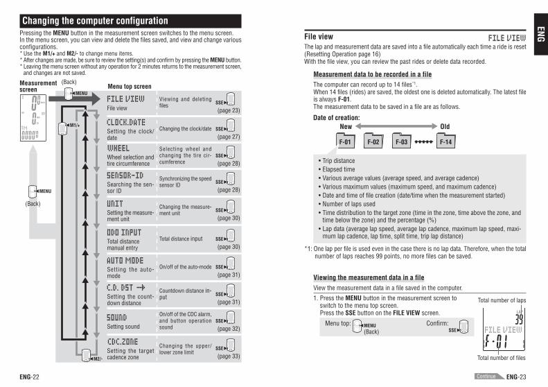
F-01 F-02 F-03 F-14
• Trip distance• Elapsed time• Various average values (average speed, and average cadence)• Various maximum values (maximum speed, and maximum cadence)• Date and time of file creation (date/time when the measurement started)• Number of laps used• Time distribution to the target zone (time in the zone, time above the zone, and
time below the zone) and the percentage (%)• Lap data (average lap speed, average lap cadence, maximum lap speed, maxi-
mum lap cadence, lap time, split time, trip lap distance)
*1: One lap per file is used even in the case there is no lap data. Therefore, when the totalnumber of laps reaches 99 points, no more files can be saved.
Viewing the measurement data in a fileView the measurement data in a file saved in the computer.
1. Press the MENU button in the measurement screen toswitch to the menu top screen.Press the SSE button on the FILE VIEW screen.
Menu top: MENU Confirm:SSE
File viewThe lap and measurement data are saved into a file automatically each time a ride is reset(Resetting Operation page 16)With the file view, you can review the past rides or delete data recorded.
Measurement data to be recorded in a fileThe computer can record up to 14 files*1.When 14 files (rides) are saved, the oldest one is deleted automatically. The latest fileis always F-01.The measurement data to be saved in a file are as follows.
Date of creation:Old
Total number of laps
Total number of files
(Back)
New
M2/-
Changing the computer configurationPressing the MENU button in the measurement screen switches to the menu screen.In the menu screen, you can view and delete the files saved, and view and change variousconfigurations.* Use the M1/+ and M2/- to change menu items.* After changes are made, be sure to review the setting(s) and confirm by pressing the MENU button.* Leaving the menu screen without any operation for 2 minutes returns to the measurement screen,
and changes are not saved.
Menu top screenMeasurementscreen
M1/+
MENU
(Back)Setting the measure-ment unit
Changing the measure-ment unit
MENU
(Back)
SSE
(page 30)
File viewViewing and deletingfiles SSE
(page 23)
Setting the clock/date
Changing the clock/date SSE
(page 27)
Wheel selection andtire circumference
Selecting wheel andchanging the tire cir-cumference
SSE
(page 28)
Searching the sen-sor ID
Synchronizing the speedsensor ID SSE
(page 28)
Total distancemanual entry
Total distance input SSE
(page 30)
Setting the auto-mode
On/off of the auto-mode SSE
(page 31)
Setting the count-down distance
Countdown distance in-put SSE
(page 31)
Setting sound
On/off of the CDC alarm,and button operationsound
SSE
(page 32)
Setting the targetcadence zone
Changing the upper/lower zone limit
SSE
(page 33)
Continue
ENG-25ENG-24
ENG
2
3
1
5
48
7
6
2
3
4
1
6
5
8
7
9
9
0
0
q
q
SSE
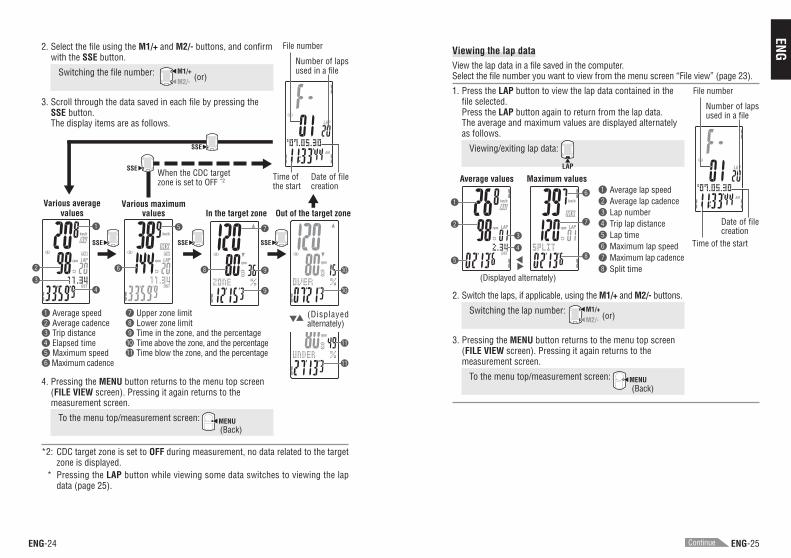
Viewing the lap dataView the lap data in a file saved in the computer.Select the file number you want to view from the menu screen “File view” (page 23).
1. Press the LAP button to view the lap data contained in thefile selected.Press the LAP button again to return from the lap data.The average and maximum values are displayed alternatelyas follows.
Viewing/exiting lap data:
LAP
2. Switch the laps, if applicable, using the M1/+ and M2/- buttons.
Switching the lap number: M1/+M2/-
3. Pressing the MENU button returns to the menu top screen(FILE VIEW screen). Pressing it again returns to themeasurement screen.
To the menu top/measurement screen: MENU
1 Average lap speed2 Average lap cadence3 Lap number4 Trip lap distance5 Lap time6 Maximum lap speed7 Maximum lap cadence8 Split time
(or)
(Displayed alternately)
(Back)
Average values Maximum values
2. Select the file using the M1/+ and M2/- buttons, and confirmwith the SSE button.
Switching the file number: M1/+M2/-
3. Scroll through the data saved in each file by pressing theSSE button.The display items are as follows.
(or)
Various averagevalues
Various maximumvalues Out of the target zone
(Displayedalternately)
When the CDC targetzone is set to OFF *2 Time of
the start
File number
Number of lapsused in a file
Date of filecreation
1 Average speed2 Average cadence3 Trip distance4 Elapsed time5 Maximum speed6 Maximum cadence
7 Upper zone limit8 Lower zone limit9 Time in the zone, and the percentage0 Time above the zone, and the percentageq Time blow the zone, and the percentage
In the target zone
4. Pressing the MENU button returns to the menu top screen(FILE VIEW screen). Pressing it again returns to themeasurement screen.
To the menu top/measurement screen: MENU
*2: CDC target zone is set to OFF during measurement, no data related to the targetzone is displayed.
* Pressing the LAP button while viewing some data switches to viewing the lapdata (page 25).
(Back)
SSE SSE SSE
SSE
Continue
Time of the start
File number
Number of lapsused in a file
Date of filecreation
ENG-27ENG-26
ENGM2/- M1/+
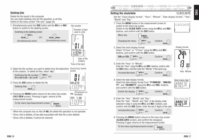
2. Select the file number you want to delete from the date/clockof file creation. To delete all files, select “aLL”.
Switching the file number: M1/+M2/-
3. Press the SSE button to delete the file.
Deleting files: SSE
4. Pressing the MENU button returns to the menu top screen(FILE VIEW screen). Pressing it again returns to themeasurement screen.
To the menu top/measurement screen: MENU
* When the computer has no files (F-00) the delete file operation is not operable.* Once a file is deleted, all lap data associated with that file is also deleted.* Once a file is deleted, it cannot be restored.
Setting the clock/dateSet the “Clock display format”, “Hour”, “Minute”, “Date display format”, “Year”,“Month” and “Day.”
1. Press the MENU button in the measurement screen toswitch to the menu top screen.Switch to the CLOCK.DATE screen using the M1/+ and M2/-buttons, and confirm with the SSE button.
Menu top: MENU
Changing the menu: M1/+M2/-
Confirm:SSE
2. Select the clock display format.Select “24 hour” or “12 hour” using the M1/+ and M2/-buttons, and confirm with the SSE button.
24h ↔↔↔↔↔ 12h: M1/+M2/-
Confirm:SSE
3. Enter the “Hour” or “Minute.”Enter the “Hour” using the M1/+ and M2/- buttons, confirm withthe SSE button, and then enter the “Minute” in the same way.
Increase/decrease: M1/+M2/-
Confirm:SSE
4. Select the date display format.Select the date display format from “YY/MM/DD”, “MM/DD/YY”, and “DD/MM/YY” using the M1/+ and M2/- buttons,and confirm with the SSE button.
Switch the display: M1/+M2/-
Confirm:SSE
5. Enter the “Year”, “Month” and “Day.”Enter the “Year”, “Month” and “Day” in the display orderselected in Step 4 using the M1/+ and M2/- buttons, andconfirm with the SSE button. Enter the last 2 digits of the year.
Increase/decrease: M1/+M2/-
Confirm:SSE
6. Pressing the MENU button returns to the menu top screen(CLOCK.DATE screen), and confirm the change(s).Pressing it again returns to the measurement screen.
To the menu top/measurement screen: MENU
(or)
(or)
(or)
(or)
Hour Minute
(or)
Display format
(Back)
(Back)
Deleting filesDelete the file saved in the computer.You can select deleting only the file specified, or all files.Switch to the menu screen “File view” (page 23).
1. Simultaneously press the SSE button and the M1/+ or M2/-button to switch to the deleting screen.
Switching to the deleting screen:M1/+
SSE SSE M2/-
(Simultaneously press) (Simultaneously press)(or)
(Displayed al-ternately)
(or)01 ↔↔↔↔↔ 02 ↔↔↔↔↔ 03 ⋅⋅⋅⋅⋅⋅⋅⋅⋅⋅⋅⋅⋅⋅⋅ aLL ↔↔↔↔↔ 01
Searching deletescreen
(Back)
Time of the start
File number
Number of lapsused in a file
Date of filecreation
ENG-29ENG-28
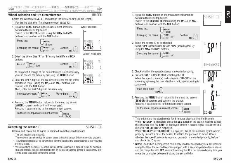
ENGM2/- M1/+
1. Press the MENU button on the measurement screen toswitch to the menu top screen.Switch to the SEnSOR-ID screen using the M1/+ and M2/-buttons, and confirm with the SSE button.
Menu top: MENU
Changing the menu: M1/+M2/-
Confirm:SSE
2. Select the sensor ID to be checked.Select “SP1 (speed sensor 1)” and “SP2 (speed sensor 2)”using the M1/+ and M2/- buttons.
Selecting the sensor: M1/+M2/-
3. Check whether the speed/cadence is mounted properly.4. Press the SSE button to start searching the ID.
When the speed (cadence) is displayed as “ID-OK” on thescreen by spinning the rear wheel or crank, synchronizing iscompleted.
Start searching: SSE
5. Pressing the MENU button returns to the menu top screen(SEnSOR-ID screen), and confirm the change.Pressing it again returns to the measurement screen.
To the menu top/measurement screen: MENU
* This unit enters the search mode for 5 minutes after starting the ID synch.While “ID-SKIP” is indicated, press the SSE button in the search mode to cancelthe ID synch, and “ID-SKIP” is displayed. Unless a sensor signal is received in 5minutes, “ID-ERROR” is displayed.When “ID-SKIP” or “ID-ERROR” is displayed, the ID has not been synchronizedproperly. In such a case, the sensor ID retains the previous ID setup. Checkwhether the speed/cadence is mounted properly, is mounted properly, beforeyou check the ID again.
* SP2 is used when a computer is commonly used for second bicycles. By synchro-nizing the ID of the second bicycle equipped with a second speed/cadence sensorand the computer with SP2, re-synchronizing the ID is not required every time youmove the computer between first and the second bike.
(or)
(or)
(Back)
(Back)
Wheel selection and tire circumferenceSwitch the Wheel Size (A / B), and change the Tire Size (tire roll out length).* For the tire size, see “Tire circumference” (page 12).
1. Press the MENU button in the measurement screen toswitch to the menu top screen.Switch to the WHEEL screen using the M1/+ and M2/-buttons, and confirm with the SSE button.
Menu top: MENU
Changing the menu: M1/+M2/-
Confirm:SSE
2. Select the Wheel Size “A” or “B” using the M1/+ and M2/-buttons.
A ↔ B: M1/+M2/-
Confirm:SSE
At this point if change of tire circumference is not necessary,you can escape the setup by pressing the MENU button.
3. Enter the last 2 digits of the tire circumference for the wheelselected in Step 1 using the M1/+ and M2/- buttons, andconfirm with the SSE button.Then, enter the first 2 digits in the same way.
Increase/decrease: M1/+M2/-
Move digits:SSE
4. Pressing the MENU button returns to the menu top screen(WHEEL screen), and confirm the change(s).Pressing it again returns to the measurement screen.
To the menu top/measurement screen: MENU
Searching the sensor IDReceive and check the ID signal transmitted from the speed/cadence.* This unit requires the sensor ID.
The computer cannot receive the sensor signal unless the sensor ID is synchronized properly.* To synchronize the sensor ID, be within 5m from the bicycle with a speed/cadence sensor mounted
properly (page 7).* When searching the sensor ID, make sure no other sensors are in the area within 10 m radius.
It is also possible to press the Reset button on the Speed/Cadence sensor to intentionally turnoff the signal transmission from the sensor.
(or)
Wheel selection
Current wheel size
(or)
(or)
(Back)
(Back)
ENG-31ENG-30
ENGM2/- M1/+M2/- M1/+
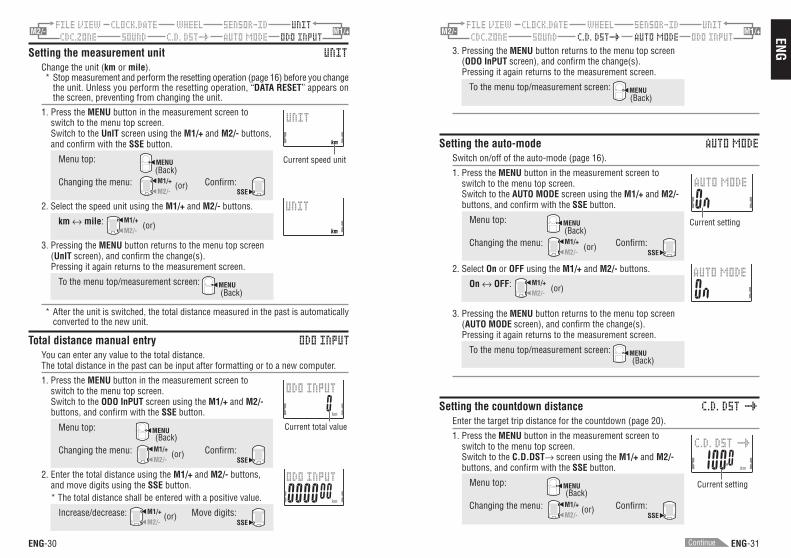
3. Pressing the MENU button returns to the menu top screen(ODO InPUT screen), and confirm the change(s).Pressing it again returns to the measurement screen.
To the menu top/measurement screen: MENU
Setting the auto-modeSwitch on/off of the auto-mode (page 16).
1. Press the MENU button in the measurement screen toswitch to the menu top screen.Switch to the AUTO MODE screen using the M1/+ and M2/-buttons, and confirm with the SSE button.
Menu top: MENU
Changing the menu: M1/+M2/-
Confirm:SSE
2. Select On or OFF using the M1/+ and M2/- buttons.
On ↔ OFF: M1/+M2/-
3. Pressing the MENU button returns to the menu top screen(AUTO MODE screen), and confirm the change(s).Pressing it again returns to the measurement screen.
To the menu top/measurement screen: MENU
Setting the countdown distanceEnter the target trip distance for the countdown (page 20).
1. Press the MENU button in the measurement screen toswitch to the menu top screen.Switch to the C.D.DST→ screen using the M1/+ and M2/-buttons, and confirm with the SSE button.
Menu top: MENU
Changing the menu: M1/+M2/-
Confirm:SSE
(or)
(or)
Current setting
Current setting
(or)
(Back)
(Back)
(Back)
(Back)
Setting the measurement unitChange the unit (km or mile).* Stop measurement and perform the resetting operation (page 16) before you change
the unit. Unless you perform the resetting operation, “DATA RESET” appears onthe screen, preventing from changing the unit.
1. Press the MENU button in the measurement screen toswitch to the menu top screen.Switch to the UnIT screen using the M1/+ and M2/- buttons,and confirm with the SSE button.
Menu top: MENU
Changing the menu: M1/+M2/-
Confirm:SSE
2. Select the speed unit using the M1/+ and M2/- buttons.
km ↔ mile: M1/+M2/-
3. Pressing the MENU button returns to the menu top screen(UnIT screen), and confirm the change(s).Pressing it again returns to the measurement screen.
To the menu top/measurement screen: MENU
* After the unit is switched, the total distance measured in the past is automaticallyconverted to the new unit.
Total distance manual entryYou can enter any value to the total distance.The total distance in the past can be input after formatting or to a new computer.
1. Press the MENU button in the measurement screen toswitch to the menu top screen.Switch to the ODO InPUT screen using the M1/+ and M2/-buttons, and confirm with the SSE button.
Menu top: MENU
Changing the menu: M1/+M2/-
Confirm:SSE
2. Enter the total distance using the M1/+ and M2/- buttons,and move digits using the SSE button.* The total distance shall be entered with a positive value.
Increase/decrease: M1/+M2/-
Move digits:SSE
(or)
(or)
(or)
Current speed unit
Current total value
(Back)
(Back)
(Back)
(or)
Continue
ENG-33ENG-32
ENGM2/- M1/+M2/- M1/+
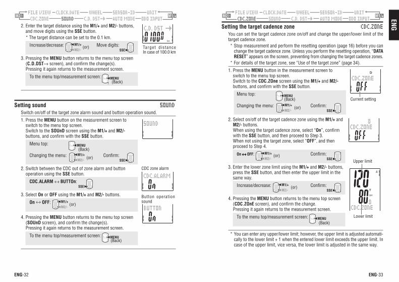
Setting the target cadence zoneYou can set the target cadence zone on/off and change the upper/lower limit of thetarget cadence zone.* Stop measurement and perform the resetting operation (page 16) before you can
change the target cadence zone. Unless you perform the resetting operation, “DATARESET” appears on the screen, preventing from changing the target cadence zones.
* For details of the target zone, see “Use of the target zone” (page 34).
1. Press the MENU button in the measurement screen toswitch to the menu top screen.Switch to the CDC.ZOne screen using the M1/+ and M2/-buttons, and confirm with the SSE button.
Menu top: MENU
Changing the menu: M1/+M2/-
Confirm:SSE
2. Select on/off of the target cadence zone using the M1/+ andM2/- buttons.When using the target cadence zone, select “On”, confirmwith the SSE button, and then proceed to Step 3.When not using the target zone, select “OFF”, and thenproceed to Step 4.
On ↔↔↔↔↔ OFF: M1/+M2/-
Confirm:SSE
3. Enter the lower zone limit using the M1/+ and M2/- buttons,press the SSE button, and then enter the upper limit in thesame way.
Increase/decrease: M1/+M2/-
Confirm:SSE
4. Pressing the MENU button returns to the menu top screen(CDC.ZOnE screen), and confirm the change.Pressing it again returns to the measurement screen.
To the menu top/measurement screen: MENU
* You can enter any upper/lower limit; however, the upper limit is adjusted automati-cally to the lower limit + 1 when the entered lower limit exceeds the upper limit. Incase of the upper limit, vice versa, the lower limit is adjusted in the same way.
2. Enter the target distance using the M1/+ and M2/- buttons,and move digits using the SSE button.* The target distance can be set to the 0.1 km.
Increase/decrease: M1/+M2/-
Move digits:SSE
3. Pressing the MENU button returns to the menu top screen(C.D.DST→ screen), and confirm the change(s).Pressing it again returns to the measurement screen.
To the menu top/measurement screen: MENU
Setting soundSwitch on/off of the target zone alarm sound and button operation sound.
1. Press the MENU button on the measurement screen toswitch to the menu top screen.Switch to the SOUnD screen using the M1/+ and M2/-buttons, and confirm with the SSE button.
Menu top: MENU
Changing the menu: M1/+M2/-
Confirm:SSE
2. Switch between the CDC out of zone alarm and buttonoperation using the SSE button.
CDC.ALARM ↔ BUTTOn: SSE
3. Select On or OFF using the M1/+ and M2/- buttons.
On ↔ OFF: M1/+M2/-
4. Pressing the MENU button returns to the menu top screen(SOUnD screen), and confirm the change(s).Pressing it again returns to the measurement screen.
To the menu top/measurement screen: MENU
(or) Target d is tanceIn case of 100.0 km
(or)
(Back)
(or)
(Back)
CDC zone alarm
Button operationsound
(or)
(or)
(or)
(Back)
(Back)
Current setting
Upper limit
Lower limit
(Back)
ENG-35ENG-34
ENG
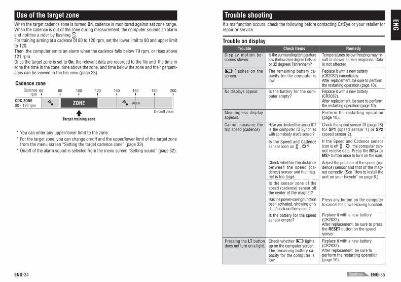
60 80 100 120 140 160 180 200rpm
Cadence
CDC.ZONE80 - 120 rpm
Cadence zone
Default zone
Target training zone
AlarmZONE
Trouble shootingIf a malfunction occurs, check the following before contacting CatEye or your retailer forrepair or service.
Trouble on display
Use of the target zoneWhen the target cadence zone is turned On, cadence is monitored against set zone range.When the cadence is out of the zone during measurement, the computer sounds an alarmand notifies a rider by flashing .For training aiming at a cadence of 80 to 120 rpm, set the lower limit to 80 and upper limitto 120.Then, the computer emits an alarm when the cadence falls below 79 rpm, or rises above121 rpm.Once the target zone is set to On, the relevant data are recorded to the file and the time inzone the time in the zone, time above the zone, and time below the zone and their percent-ages can be viewed in the file view (page 23).
* You can enter any upper/lower limit to the zone.* For the target zone, you can change on/off and the upper/lower limit of the target zone
from the menu screen “Setting the target cadence zone” (page 33).* On/off of the alarm sound is selected from the menu screen “Setting sound” (page 32).
Trouble Check Items RemedyDisplay motion be-comes slower.
Flashes on thescreen.
No displays appear.
Meaningless displayappears.
Cannot measure thetrip speed (cadence)
Is the surrounding temperaturelow (below zero degree Celsiusor 32 degrees Fahrenheit)?
Temperatures below freezing may re-sult in slower screen response. Datais not affected.
The remaining battery ca-pacity for the computer islow.
Replace it with a new battery(CR2032) immediately.After replacement, be sure to performthe restarting operation (page 10).
Is the battery for the com-puter empty?
Replace it with a new battery(CR2032).After replacement, be sure to performthe restarting operation (page 10).
Perform the restarting operation(page 10).
Have you checked the sensor ID?Is the computer ID Synch'edwith somebody else's sensor?
Is the Speed and Cadencesensor icon on , ?
Check whether the distancebetween the speed (ca-dence) sensor and the mag-net is too large.Is the sensor zone of thespeed (cadence) sensor offthe center of the magnet?Has the power-saving functionbeen activated, showing onlydate/clock on the screen?Is the battery for the speedsensor empty?
Check the speed sensor ID (page 28)for SP1 (speed sensor 1) or SP2(speed sensor 2).
If the Speed and Cadence sensoricon is off , , the computer can-not receive data. Press the M1/+ orM2/- button once to turn on the icon.
Adjust the position of the speed (ca-dence) sensor and that of the mag-net correctly. (See “How to install theunit on your bicycle” on page 6.)
Press any button on the computerto cancel the power-saving function.
Replace it with a new battery(CR2032).After replacement, be sure to pressthe RESET button on the speedsensor.
Continue
Pressing the LT buttondoes not turn on a light.
Check whether lightsup on the computer screen.The remaining battery ca-pacity for the computer islow.
Replace it with a new battery(CR2032).After replacement, be sure toperform the restarting operation(page 10).
ENG-37ENG-36
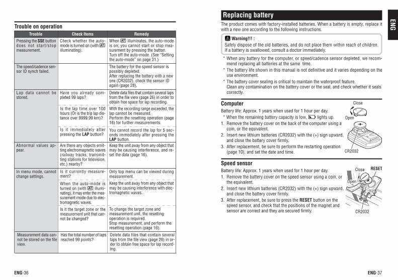
ENGReplacing battery
The product comes with factory-installed batteries. When a battery is empty, replace itwith a new one according to the following instructions.
Warning!!! :Safely dispose of the old batteries, and do not place them within reach of children.If a battery is swallowed, consult a doctor immediately.
* When any battery for the computer, or speed/cadence sensor depleted, we recom-mend replacing all batteries at the same time.
* The battery life shown in this manual is not definitive and it varies depending on theuse environment.
* The battery cover sealing is critical to maintain the waterproof feature.Clean any contamination on the battery cover or the seal, and check whether it sealscorrectly.
ComputerBattery life: Approx. 1 years when used for 1 hour per day.* When the remaining battery capacity is low, lights up.
1. Remove the battery cover on the back of the computer using acoin, or the equivalent.
2. Insert new lithium batteries (CR2032) with the (+) sign upward,and close the battery cover firmly.
3. After replacement, be sure to perform the restarting operation(page 10), and set the date and time.
Speed sensorBattery life: Approx. 1 years when used for 1 hour per day.1. Remove the battery cover on the speed sensor using a coin, or
the equivalent.2. Insert new lithium batteries (CR2032) with the (+) sign upward,
and close the battery cover firmly.3. After replacement, be sure to press the RESET button on the
speed sensor, and check that the positions of the magnet andsensor are correct and they are secured firmly.
RESETIn menu mode, cannotchange settings.
Is it currently measure-ment?
When the auto-mode isturned on (with illumi-nating), it may enter the mea-surement mode due to elec-tromagnetic waves.
Is it the target zone or themeasurement unit that can-not be changed?
Only top menu can be viewed duringmeasurement.
Keep the unit away from any object thatmay be causing interference with elec-tromagnetic waves.
To change the target zone andmeasurement unit, the resettingoperation is required.Stop measurement, and perform theresetting operation (page 16).
Trouble on operation
Pressing the SSE buttondoes not start/stopmeasurement.
Check whether the auto-mode is turned on (with illuminating).
When illuminates, the auto-modeis on; you cannot start or stop mea-surement by pressing the button.Turn off the auto-mode. (See “Settingthe auto-mode” on page 31.)
The speed/cadence sen-sor ID synch failed.
The battery for the speed sensor ispossibly depleted.After replacing the battery with a newone (CR2032), check the sensor IDagain (page 28).
Lap data cannot bestored.
Have you already com-pleted 99 laps?
Is the lap time over 100hours (Or is the trip lap dis-tance over 9999.99 km)?
Is it immediately afterpressing the LAP button?
Delete data files that contain several lapsfrom the file view (page 26) in order toobtain free space for lap recording.With the recording range exceeded, thelap cannot be measured.Perform the resetting operation (page16) for further measurements.
You cannot record the lap for 5 sec-onds immediately after pressing theLAP button.
Trouble Check Items Remedy
Abnormal values ap-pear.
Are there any objects emit-ting electromagnetic waves(railway tracks, transmit-ting stations for television,etc.) nearby?
Keep the unit away from any object thatmay be causing interference, and re-set the data (page 16).
Measurement data can-not be stored on the fileview.
Has the total number of lapsreached 99 points?
Delete data files that contain severallaps from the file view (page 26) in or-der to obtain free space for lap record-ing.
CR2032
Close
Open
Close
Open
CR2032
ENG-39ENG-38
ENG
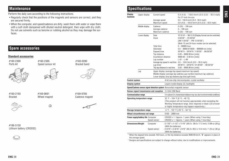
Spare accessories
MaintenancePerform the daily care according to the following instructions.• Regularly check that the positions of the magnets and sensors are correct, and they
are secured firmly.• When the computer, and speed/cadence are dirty, wash them with water or wipe them
with a soft cloth dampened with diluted neutral detergent, then wipe with dry cloth.Do not use solvents such as benzine or rubbing alcohol as they may damage the sur-faces.
SpecificationsUpper display Current speed 0.0 (4.0) − 150.0 km/h [0.0 (3.0) − 93.0 mph]
For 27-inch tire sizeAverage speed 0.0 - 150.0 km/h [0.0 - 93.0 mph]Maximum speed 0.0 (4.0) − 150.0 km/h [0.0 (3.0) − 93.0 mph]
Middle display Cadence 0 (20) − 199 rpmAverage cadence 0 − 199 rpmMaximum cadence 0 (20) − 199 rpm
Lower display Date ‘07.01.01 − '99.12.31(Display format can be switched)Clock 0:00’00” − 23:59’59”
[AM 1:00’00” − PM 12:59’59”](Both 12 and 24-hour modes can be selected)
Total time 0 − 99999 hourOdometer 0.0 − 9999.9/10000 − 999999 km [mile]Elapsed time 00’00”0 − 59’59”9 / 1:00’00” − 99:59’59”Trip distance 0.00 − 9999.99 km [mile]Countdown distance 9999.90 − 0.00 km [mile]Lap number L-01 − L-99Average lap speed in real time 0.0 − 150.0 km/h [0.0 − 93.0 mph]Lap timer 00’00”0 − 59’59”9 / 01:00’00” − 99:59’59”Trip lap distance in real time 0.00 − 9999.99 km [mile]
Lap Upper display (average lap speed,maximum lap speed)Middle display (average lap cadence,Lap number,maximum lap cadence)Lower display (trip lap distance,lap time,split time)
Control system 4-bit one-chip microcomputer, crystal oscillator
Display system Liquid crystal display (EL backlight)
Speed/Cadence sensor signal detection system Noncontact magnetic sensor
Sensor signal transmission and reception 2.4 GHz ISM Band
Communication range 5 m (above 5 m, transmission distance may vary due to environmental conditions)
Operating temperature range 32 °F − 104 °F [0 °C − 40 °C](This product will not function appropriately when exceeding theWorking Temperature range. Slow response or black LCD at loweror higher temperature may happen respectively.)
Storage temperature range -4 °F − 122 °F [-20 °C − 50 °C]
Wheel circumference set range 0100 − 3999 mm
Power supply/battery life Computer : CR2032 x 1 / Approx. 1 years (When using 1 hour/day)Speed sensor : CR2032 x 1 / Approx. 1 years (When using 1 hour/day)
Dimensions/Weight Computer : 2-7/32” x 1-1/2” x 11/16” (56.0 x 38.0 x 17.3 mm) / 0.98 oz (28 g)(With the batteries)
Speed sensor : 2-9/16” x 3-9/16” x 9/16” (65.0 x 90.5 x 14.4 mm) / 1.25 oz (36 g)(With the batteries)
* When the elapsed time exceeds 100 hours, or the trip distance exceeds 9999.99 km/h, “E” appears in place ofthe average speed.
* Designs and specifications are subject to change without notice, due to modifications or improvements.
Displayfunctions
Standard accessories
#160-2380Parts kit
#160-2385Speed sensor kit
#160-0280Bracket band
#160-2193Bracket
#169-9691Wheel magnet
#169-9766Cadence magnet
#166-5150Lithium battery (CR2032)
ENG-40
Limited warranty2-Year: computer, and speed sensor
(Not including depletion of batteries)CatEye products are warranted to be free of defects from materials and workmanship fora period of two years from original purchase. If the product fails to work due to normaluse, CatEye will repair or replace the defect at no charge. Service must be performed byCatEye or an authorized retailer.To return the product, pack it carefully and enclose the warranty certificate (proof orpurchase) with instruction for repair. Please write or type your name and address clearlyon the warranty certificate.Insurance, handling and transportation charges to CatEye shall be borne by person desir-ing service.For UK and REPUBLIC OF IRELAND consumers, please return to the place of purchase.This does not affect your statutory rights.
RegistrationCATEYE Web Site (http://www.cateye.com)For warranty service you must confirm your product. Please confirm your V2c as soon aspossible. CATEYE provides you technical support and new product information as muchas possible.Please confirm on-line through our web site, or send the registration card below directlyto our Customer Service Department. For registration, please fill in the product's serialnumber (the 7-digits number marked on on the battery cover of computer).
CO.,LTD.Service & Research Address for USA:CATEYE Service and Research Center1705 14th St. 115 Boulder, CO 80302Phone: 303.443.4595 Fax: 303.473.0006Toll Free: 800.5CATEYE E-mail: [email protected]: http://www.cateye.comJapan Office:2-8-25, Kuwazu, Higashi Sumiyoshi-ku, Osaka 546-0041 JapanAttn: CATEYE Customer Service Section