Embed Size (px)
DESCRIPTION
es un catalogo de quemadores de gas en el cuals se mustran mucha información
Citation preview
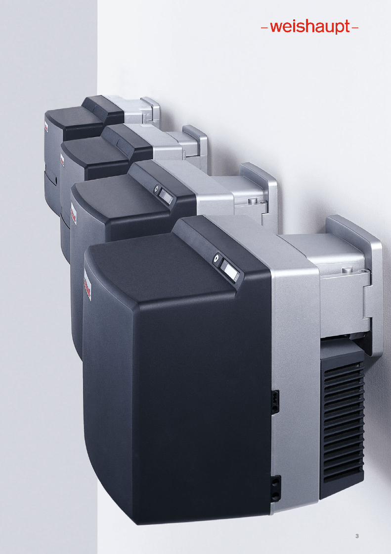
productInformation on compact burners
Digital combustion technologyWeishaupt gas burners WG5 to WG40 (12.5–550 kW)
A burning passion for quality
2
We are motivated by technological progress and this aim has been drivingus for more than 60 years to set new standards for the combustion industry.
Weishaupt’s own Research and Development Centre is constantly working on both new developmentsand the optimisation of exisiting products.
It is both our goal and our responsibilityto go above and beyond current legislative requirements in developingcombustion systems which producefewer and fewer emissions, save moreand more energy, and in so doing serveto combine ecology and economy in apractical manner.
Therefore, not only do we invest in research and technology but we alsoonly ever work on the best materialswith modern tools and we carry out meticulous quality control checks.
It has been proven over a million timesin the field that heating specialists andcustomers hold Weishaupt burners tobe reliable, long lasting, environmentallyfriendly and technologically advanced.A fact also documented by numerous design and innovation prizes.
Over 600 burners are manufactureddaily at our ultra-modern production facilities in Germany. Every single burner is subjected to a mechanical andelectrical function test. This combinationof technology with an effective qualitycontrol system safeguards Weishaupt’sreknowned reputation for quality.
A new burner is always an investment in the future. Cost needs to be well- balanced against use, but the final deciding factors for long-term successare quality, technology, and reliability. Opting for Weishaupt burners is therefore always a safe investment inthe future.
Ultra-modern research and production methods and rigourous quality control ensures the quality for whichWeishaupt is reknowned.
3
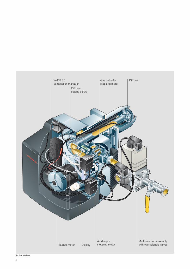
Typical WG40
W-FM 25combustion manager
Diffuser setting screw
Diffuser
Burner motor DisplayMulti-function assemblywith two solenoid valves
Gas butterflystepping motor
Air damperstepping motor
4
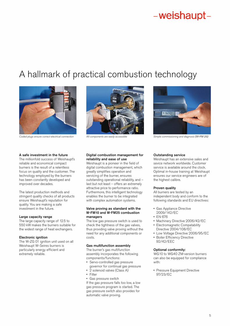
A hallmark of practical combustion technology
5
A safe investment in the futureThe millionfold success of Weishaupt’sreliable and economical compact burners is the result of a relentlessfocus on quality and the customer. Thetechnology employed by the burnershas been constantly developed and improved over decades.
The latest production methods and stringent quality checks of all productsensure Weishaupt’s reputation for quality. You are making a safeinvestment in the future.
Large capacity rangeThe large capacity range of 12.5 to550 kW makes the burners suitable forthe widest range of heat exchangers.
Electronic ignitionThe W-ZG 01 ignition unit used on allWeishaupt W-Seires burners is particularly energy efficient and extremely reliable.
Digital combustion management forreliability and ease of useWeishaupt is a pioneer in the field of digital combustion management, whichgreatly simplifies operation and servicing of the burner, ensures outstanding operational reliability, and –last but not least – offers an extremelyattractive price to performance ratio.Furthermore, this intelligent technologyenables the burner to be integratedwith complex automation systems.
Valve proving as standard with theW-FM10 and W-FM25 combustionmanagersThe low gas pressure switch is used tocheck the tightness of the gas valves,thus providing valve proving without theneed for any additional components orcosts.
Gas multifunction assemblyThe burner’s gas multifunction assembly incorporates the following components/functions:• Servo-controlled gas pressure
governor for continual gas pressure• 2 solenoid valves (Class A)• Filter• Gas pressure switchIf the gas pressure falls too low, a lowgas pressure program is started. Thegas pressure switch also provides forautomatic valve proving.
Outstanding serviceWeishaupt has an extensive sales andsevice network worldwide. Customerservice is available around the clock.Optimal in-house training at Weishauptensures our service engineers are ofthe highest calibre.
Proven quality All burners are tested by an independent body and conform to thefollowing standards and EU directives:
• Gas Appliance Directive2009/142/EC
• EN 676• Machinery Directive 2006/42/EC• Electromagnetic Compatability
Directive 2004/108/EC• Low Voltage Directive 2006/95/EC• Boiler Efficiency Directive
92/42/EEC
Optional conformity:WG10 to WG40 ZM-version burnerscan also be equipped for compliancewith:
• Pressure Equipment Directive97/23/EC
Coded plugs ensure correct electrical connection All components are easily accessible Simple commissioning and diagnosis (W-FM 25)
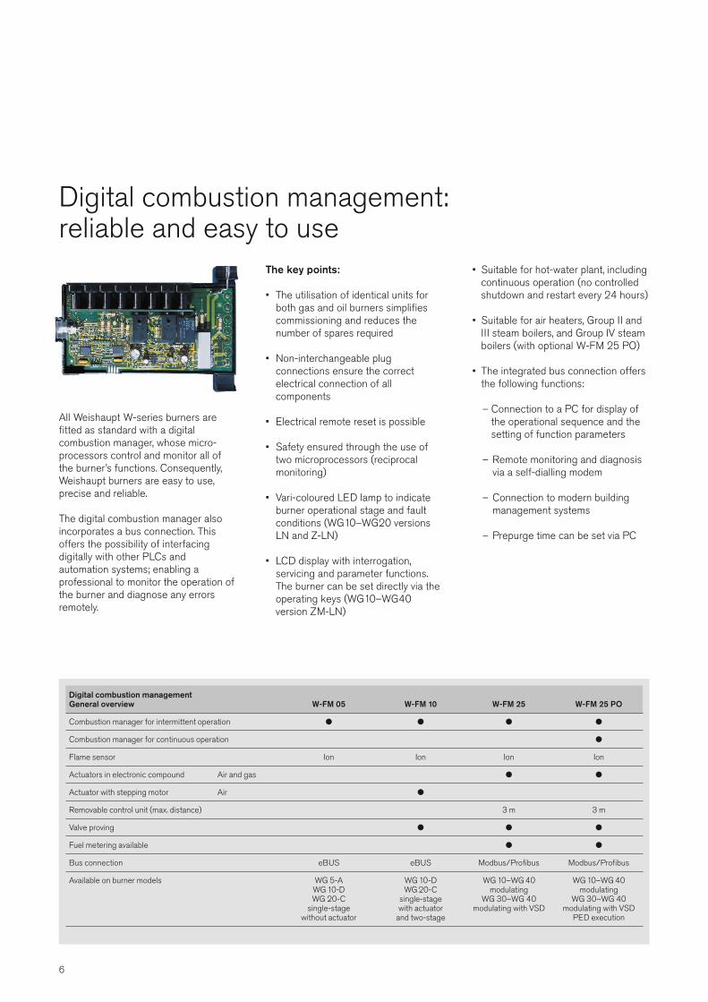
Digital combustion management:reliable and easy to use
6
All Weishaupt W-series burners are fitted as standard with a digital combustion manager, whose micro -processors control and monitor all ofthe burner’s functions. Consequently,Weishaupt burners are easy to use, precise and reliable.
The digital combustion manager alsoincorporates a bus connection. This offers the possibility of interfacing digitally with other PLCs and automation systems; enabling a professional to monitor the operation ofthe burner and diagnose any errors remotely.
The key points:
• The utilisation of identical units forboth gas and oil burners simplifies commissioning and reduces the number of spares required
• Non-interchangeable plug connections ensure the correct electrical connection of all components
• Electrical remote reset is possible
• Safety ensured through the use oftwo microprocessors (reciprocal monitoring)
• Vari-coloured LED lamp to indicateburner operational stage and faultconditions (WG10–WG20 versionsLN and Z-LN)
• LCD display with interrogation, servicing and parameter functions.The burner can be set directly via theoperating keys (WG10–WG40 version ZM-LN)
• Suitable for hot-water plant, includingcontinuous operation (no controlledshutdown and restart every 24 hours)
• Suitable for air heaters, Group II andIII steam boilers, and Group IV steamboilers (with optional W-FM 25 PO)
• The integrated bus connection offersthe following functions:
– Connection to a PC for display ofthe operational sequence and thesetting of function parameters
– Remote monitoring and diagnosisvia a self-dialling modem
– Connection to modern building management systems
– Prepurge time can be set via PC
Digital combustion managementGeneral overview W-FM 05 W-FM 10 W-FM 25 W-FM 25 PO
Combustion manager for intermittent operation l l l l
Combustion manager for continuous operation l
Flame sensor Ion Ion Ion Ion
Actuators in electronic compound Air and gas l l
Actuator with stepping motor Air l
Removable control unit (max. distance) 3 m 3 m
Valve proving l l l
Fuel metering available l l
Bus connection eBUS eBUS Modbus/Profibus Modbus/Profibus
Available on burner models WG 5-A WG 10-D WG 10–WG 40 WG 10–WG 40 WG 10-D WG 20-C modulating modulating WG 20-C single-stage WG 30–WG 40 WG 30–WG 40 single-stage with actuator modulating with VSD modulating with VSD without actuator and two-stage PED execution
7
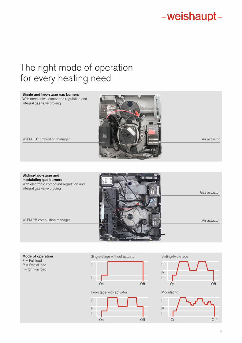
The right mode of operationfor every heating need
Mode of operationF = Full loadP = Partial loadI = Ignition load
G
Z
G
KZ
G
KZ
G
KZ
On Off
On Off
On Off
On Off
Single-stage without actuator Sliding-two-stage
Two-stage with actuator Modulating
Single and two-stage gas burnersWith mechanical compound regulation andintegral gas valve proving
W-FM 10 combustion manager Air actuator
Sliding-two-stage and modulating gas burnersWith electronic compound regulation and integral gas valve proving
W-FM 25 combustion manager Air actuator
Gas actuator
F F
FF
I I
I I
P
PP
Trustworthy technology
8
Compact designJust one look under the burner’s coveris enough to convince anyone of itsquality. All the components are clearlyarranged, the electrical connections areobvious and non-interchangeable. Theengineering is typical of Weishaupt andit makes a good impression.
Their compact design means WG burners of all ratings can be easily installed by one person. Commissioningcosts are reduced to a minimum.
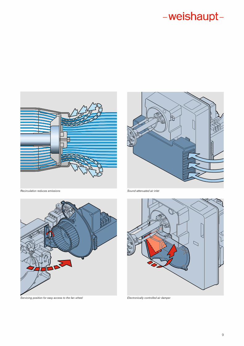
Low-NOx executionAll WG burners are Low NOx executionas standard. A specially designed mixing head produces an intensive internal flue gas recirculation, resultingin exemplary emission levels.
Sound-attenuated air inletThe transverse fan is sound attenuatedon the suction side. The burners therefore operate particularly quietly.
Electronically controlled air damperThe electronically controlled air dampercloses at burner shutdown to hinder thecooling-down of the combustion chamber.
Maintenance positionA special bracket enables the burner tobe placed into a maintenance position, providing easy access to the burner andmixing assembly.
Common platformThe common platform principle usedwith all W-Series burners simplifies theprovision and storage of spare parts.
Interrogation via laptopA special software package and connection cables are available for interrogating the combustion manager.Combustion optimisation and fault analysis can thus be carried out easilyvia a laptop computer.
9
Servicing position for easy access to the fan wheel Electronically controlled air damper
Sound-attenuated air inletRecirculation reduces emissions
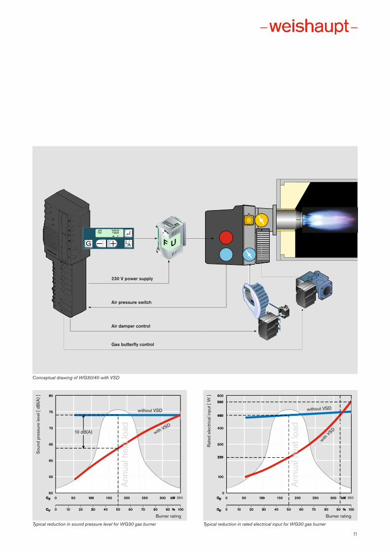
Burners with variable speed drive:economical and quietVariable speed drive (VSD)Whereas a burner motor is usually run at a constant speed, the speed ofthe motor on VSD-equipped WG30and WG40 burners is variable and depends on the prevailing burner load.The VSD is electronically controlled bythe digital combustion manager.
VSD offers the advantages of bothreduced electrical consumption and aconsiderable reduction in noise levelsat partial load.
The reduced noise levels are of particular practical benefit. A 10 dB reduction in the sound level can beachieved at 50 % burner load, whichequates to a halving of noise emissions.
FunctionalityThe Weishaupt W-FM 25 combustionmanager controls the speed of the fanby means of a frequency convertor, varying it in reponse to changes in loaddemand.
The speed of the fan, which determinesthe combustion air volume, is monitored during burner operation. The volume ofgas that is required for the speed of thefan/air volume at any given moment isregulated by the gas butterfly valve.
Benefits:
• Energy savings reduce the paybackperiod of the investment
• Reduction in burner noise emissions
• Capacity range identical to that ofthe standard, fixed-speed burners
• Good price/performance relationship
• Optimised installation, setting, andmaintenance
• High-precision, digital control
10
11
UFM
PP
600
100
0
0 10 20 30 40 50 60 70 80 % 100
0 50 100 150 200 250 300 kWQF
QF 90
560
480
220
400
300
006
084
065
003
004
220
Q
FQ 001050
320010
0
001
F
20005100
06050403
kW003052
001%0807 09
053
80
75
70
55
50
0 10 20 30 40 50 60 70 80 % 100
65
60
0 50 100 150 200 250 300 kWQF
QF 90
08
75
06
65
07
Q
FQ 001050
320010
05
55
F
20005100
06050403
kW003052
001%0807 09
053
Typical reduction in sound pressure level for WG30 gas burner Typical reduction in rated electrical input for WG30 gas burner
Conceptual drawing of WG30/40 with VSD
230 V power supply
Air pressure switch
Air damper control
Gas butterfly control
Burner rating
without VSD without VSD
Ann
ual h
eat l
oad
10 dB(A) with VSD
with VSD
Sou
nd p
ress
ure
leve
l [ d
B(A
) ]
Burner rating
Ann
ual h
eat l
oad
Rat
ed e
lect
rical
inpu
t [ W
]
12
WG5 capacity and model overviewWG5 capacity graph
3010
1,5
kW
-0,5
20-1,0
0
0,5
1,0
0605040
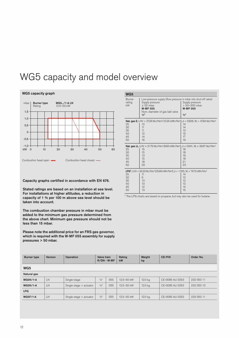
Burner Low-pressure supply (flow pressure in mbar into shut-off valve)rating Supply pressure Supply pressure kW ≤ 50 mbar > 50–300 mbar W-MF 055 W-MF 055 Nom. diameter of gas ball valve ½” ½”
Nat. gas E, LHV = 37.26 MJ/Nm3 (10.35 kWh/Nm3), d = 0.606, Wi = 47.84 MJ/Nm3
25 12 1430 11 14 35 11 1340 12 1545 14 1750 16 19
Nat. gas LL, LHV = 31.79 MJ/Nm3 (8.83 kWh/Nm3), d = 0.641, Wi = 39.67 MJ/Nm3
25 15 1830 15 1835 13 1640 15 1845 18 2150 20 23
LPG*, LHV = 93.20 MJ/Nm3 (25.89 kWh/Nm3), d = 1.555, Wi = 74.73 kWh/Nm3
25 11 1430 9 1235 10 1240 10 1345 12 1450 13 15
* The LPG charts are based on propane, but may also be used for butane.
WG5
Burner type Version Operation Valve train Rating Weight CE-PIN Order No. R/DN - W-MF kW kg
WG5Natural gas
WG5N/1-A LN Single-stage ½” 055 12.5–50 kW 12.0 kg CE-0085 AU 0353 232 050 11
WG5N/1-A LN Single-stage + actuator ½” 055 12.5–50 kW 12.0 kg CE-0085 AU 0353 232 050 10
LPG
WG5F/1-A LN Single-stage + actuator ½” 055 12.5–50 kW 12.0 kg CE-0085 AU 0353 233 050 11
Capacity graphs certified in accordance with EN 676.
Stated ratings are based on an installation at sea level.For installations at higher altitudes, a reduction in capacity of 1 % per 100 m above sea level should betaken into account.
The combustion chamber pressure in mbar must beadded to the minimum gas pressure determined fromthe above chart. Minimum gas pressure should not beless than 15 mbar.
Please note the additional price for an FRS gas governor,which is required with the W-MF 055 assembly for supplypressures > 50 mbar.
mbar Burner type WG5.../1-A LNRating 12.5–50 kW
Combustion head open Combustion head closed
13
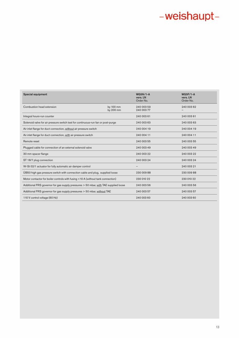
Special equipment WG5N/1-A WG5F/1-A vers. LN vers. LN Order No. Order No.
Combustion head extension by 100 mm 240 003 59 240 003 62 by 200 mm 240 003 77 –
Integral hours-run counter 240 003 61 240 003 61
Solenoid valve for air pressure switch test for continuous-run fan or post-purge 240 003 63 240 003 63
Air inlet flange for duct connection, without air pressure switch 240 004 19 240 004 19
Air inlet flange for duct connection, with air pressure switch 240 004 11 240 004 11
Remote reset 240 003 55 240 003 55
Plugged cable for connection of an external solenoid valve 240 003 49 240 003 49
30 mm spacer flange 240 003 22 240 003 22
ST 18/7 plug connection 240 003 24 240 003 24
W-St 02/1 actuator for fully automatic air damper control – 240 003 21
ÜB50 high gas pressure switch with connection cable and plug, supplied loose 230 009 88 230 009 88
Motor contactor for boiler controls with fusing <10 A (without tank connection) 230 010 22 230 010 22
Additional FRS governor for gas supply pressures > 50 mbar, with TAE supplied loose 240 003 56 240 003 56
Additional FRS governor for gas supply pressures > 50 mbar, without TAE 240 003 57 240 003 57
110 V control voltage (60 Hz) 240 003 60 240 003 60
14
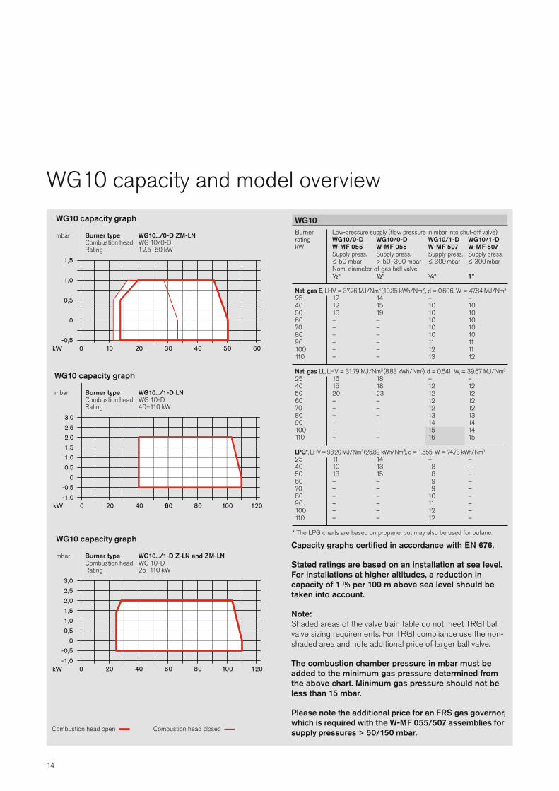
WG10 capacity and model overview
20 301-0,5
0
0,5
1,0
kW 0
1,5
0605040
Burner type WG10.../0-D ZM-LNCombustion head WG 10/0-DRating 12.5–50 kW
mbar
WG10 capacity graph
04 620-1,0-0,5
00,51,01,52,02,5
kW 0
3,0
1200010806
Burner type WG10.../1-D LNCombustion head WG 10-DRating 40–110 kW
mbar
WG10 capacity graph
0
3,0
kW 04 620-1,0-0,5
00,51,01,52,02,5
120001080
Burner type WG10.../1-D Z-LN and ZM-LNCombustion head WG 10-DRating 25–110 kW
mbar
WG10 capacity graph
Burner Low-pressure supply (flow pressure in mbar into shut-off valve)rating WG10/0-D WG10/0-D WG10/1-D WG10/1-DkW W-MF 055 W-MF 055 W-MF 507 W-MF 507 Supply press. Supply press. Supply press. Supply press. ≤ 50 mbar > 50–300 mbar ≤ 300 mbar ≤ 300 mbar Nom. diameter of gas ball valve ½” ½” ¾” 1”
Nat. gas E, LHV = 37.26 MJ/Nm3 (10.35 kWh/Nm3), d = 0.606, Wi = 47.84 MJ/Nm3
25 12 14 – –40 12 15 10 1050 16 19 10 1060 – – 10 1070 – – 10 1080 – – 10 1090 – – 11 11100 – – 12 11110 – – 13 12
Nat. gas LL, LHV = 31.79 MJ/Nm3 (8.83 kWh/Nm3), d = 0.641, Wi = 39.67 MJ/Nm3
25 15 18 – –40 15 18 12 1250 20 23 12 1260 – – 12 1270 – – 12 1280 – – 13 1390 – – 14 14100 – – 15 14110 – – 16 15
LPG*, LHV = 93.20 MJ/Nm3 (25.89 kWh/Nm3), d = 1.555, Wi = 74.73 kWh/Nm3
25 11 14 – –40 10 13 8 –50 13 15 8 –60 – – 9 –70 – – 9 –80 – – 10 –90 – – 11 –100 – – 12 –110 – – 12 –
* The LPG charts are based on propane, but may also be used for butane.
WG10
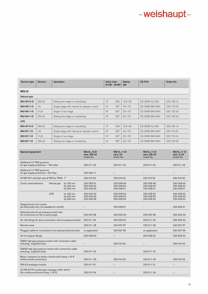
Capacity graphs certified in accordance with EN 676.
Stated ratings are based on an installation at sea level.For installations at higher altitudes, a reduction in capacity of 1 % per 100 m above sea level should betaken into account.
Note:Shaded areas of the valve train table do not meet TRGI ballvalve sizing requirements. For TRGI compliance use the non-shaded area and note additional price of larger ball valve.
The combustion chamber pressure in mbar must beadded to the minimum gas pressure determined fromthe above chart. Minimum gas pressure should not beless than 15 mbar.
Please note the additional price for an FRS gas governor,which is required with the W-MF 055/507 assemblies forsupply pressures > 50/150 mbar.Combustion head open Combustion head closed
15
Burner type Version Operation Valve train Rating CE-PIN Order No. R/DN - W-MF kW
WG10Natural gas
WG10N/0-D ZM-LN Sliding-two-stage or modulating ½” 055 12.5–50 CE-0085 AU 353 232 136 14
WG10N/1-D LN Single-stage with manual air damper control ¾” 507 40–110 CE-0085 BM 0481 232 110 24
WG10N/1-D Z-LN Single or two-stage ¾” 507 25–110 CE-0085 BM 0481 232 123 24
WG10N/1-D ZM-LN Sliding-two-stage or modulating ¾” 507 25–110 CE-0085 BM 0481 232 126 24
LPG
WG10F/0-D ZM-LN Sliding-two-stage or modulating ½” 055 12.5–50 CE-0085 AU 353 233 136 14
WG10F/1-D LN Single-stage with manual air damper control ¾” 507 40–110 CE-0085 BM 0481 233 110 24
WG10F/1-D Z-LN Single or two-stage ¾” 507 25–110 CE-0085 BM 0481 233 113 24
WG10F/1-D ZM-LN Sliding-two-stage or modulating ¾” 507 25–110 CE-0085 BM 0481 233 126 24
Special equipment WG10.../0-D WG10.../1-D WG10.../1-D WG10.../1-D vers. ZM-LN vers. LN vers. ZM-LN vers. Z-LN Order No. Order No. Order No. Order No.
Additional ¾” FRS governor for gas supply pressures > 150 mbar 230 011 02 230 011 02 230 011 02 230 011 02
Additional ½” FRS governor for gas supply pressures > 50 mbar 230 009 11 – – –
W-MF 507 with ball valve & TAE for TRGI 1” 230 010 92 230 010 92 230 010 92 230 010 92
Comb. head extension Natural gas by 100 mm 230 009 31 230 008 49 230 008 49 230 008 49 by 200 mm 230 009 32 230 008 50 230 008 50 230 008 50 by 300 mm 230 009 33 230 008 51 230 008 51 230 008 51
LPG by 100 mm 230 009 34 230 008 52 230 008 52 230 008 52 by 200 mm 230 009 35 230 008 53 230 008 53 230 008 53 by 300 mm 230 009 36 230 008 54 230 008 54 230 008 54
Integral hours-run counter(at initial build only, not available for retrofit) – 230 008 01 – 230 008 01
Solenoid valve for air pressure switch test for continuous-run fan or post-purge 230 007 98 230 003 29 230 007 98 230 003 29
Air inlet flange for duct connection, with air pressure switch 230 011 44 230 009 02 230 011 44 230 009 02
Remote reset 230 011 48 230 007 97 230 011 48 230 007 97
Plugged cable for connection of an external solenoid valve on application 230 007 96 on application 230 007 96
30 mm spacer flange 230 008 02 – 230 008 02 230 008 02
ÜB50 high gas pressure switch with connection cable and plug, supplied loose – 230 010 40 – 230 010 40
GW50 high gas pressure switch with connection cable and plug, supplied loose 230 011 42 – 230 011 42 –
Motor contactor for boiler controls with fusing <10 A (without tank connection) 230 011 39 230 010 22 230 011 39 230 010 22
EM 3/3 analogue module 230 011 51 – 230 011 51 –
W-FM 25 PO combustion manager, 230–240 V(for continuous burner firing > 24 h) 230 013 34 – 230 011 34 –
WG20 capacity and model overview
16
06 001-1,0-0,5
00,51,01,52,02,5
kW 20
3,0
08104100
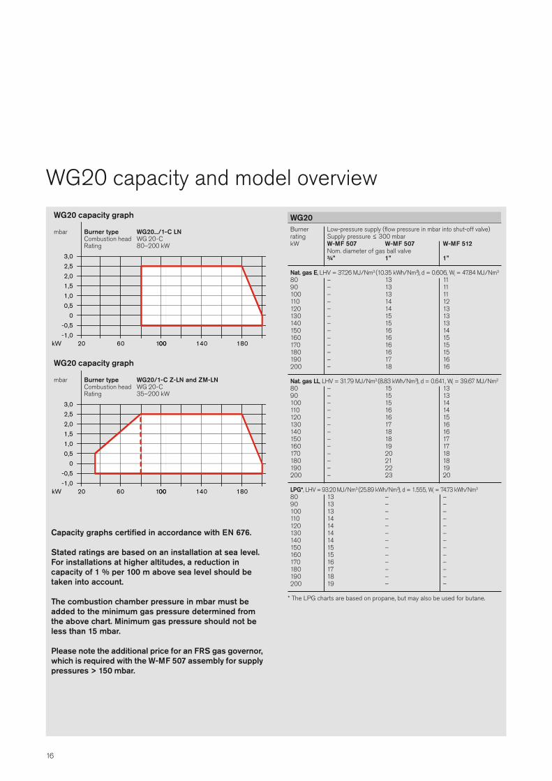
Burner type WG20.../1-C LNCombustion head WG 20-CRating 80–200 kW
mbar
WG20 capacity graph
06 001-1,0-0,5
00,51,01,52,02,5
kW 20
3,0
08104100
Burner type WG20/1-C Z-LN and ZM-LNCombustion head WG 20-CRating 35–200 kW
mbar
WG20 capacity graph
Burner Low-pressure supply (flow pressure in mbar into shut-off valve)rating Supply pressure ≤ 300 mbarkW W-MF 507 W-MF 507 W-MF 512 Nom. diameter of gas ball valve ¾” 1” 1”
Nat. gas E, LHV = 37.26 MJ/Nm3 (10.35 kWh/Nm3), d = 0.606, Wi = 47.84 MJ/Nm3
80 – 13 1190 – 13 11100 – 13 11110 – 14 12120 – 14 13130 – 15 13140 – 15 13150 – 16 14160 – 16 15170 – 16 15180 – 16 15190 – 17 16200 – 18 16
Nat. gas LL, LHV = 31.79 MJ/Nm3 (8.83 kWh/Nm3), d = 0.641, Wi = 39.67 MJ/Nm3
80 – 15 1390 – 15 13100 – 15 14110 – 16 14120 – 16 15130 – 17 16140 – 18 16150 – 18 17160 – 19 17170 – 20 18180 – 21 18190 – 22 19200 – 23 20
LPG*, LHV = 93.20 MJ/Nm3 (25.89 kWh/Nm3), d = 1.555, Wi = 74.73 kWh/Nm3
80 13 – –90 13 – –100 13 – –110 14 – –120 14 – –130 14 – –140 14 – –150 15 – –160 15 – –170 16 – –180 17 – –190 18 – –200 19 – –
* The LPG charts are based on propane, but may also be used for butane.
WG20
Capacity graphs certified in accordance with EN 676.
Stated ratings are based on an installation at sea level.For installations at higher altitudes, a reduction in capacity of 1 % per 100 m above sea level should betaken into account.
The combustion chamber pressure in mbar must beadded to the minimum gas pressure determined fromthe above chart. Minimum gas pressure should not beless than 15 mbar.
Please note the additional price for an FRS gas governor,which is required with the W-MF 507 assembly for supplypressures > 150 mbar.
17
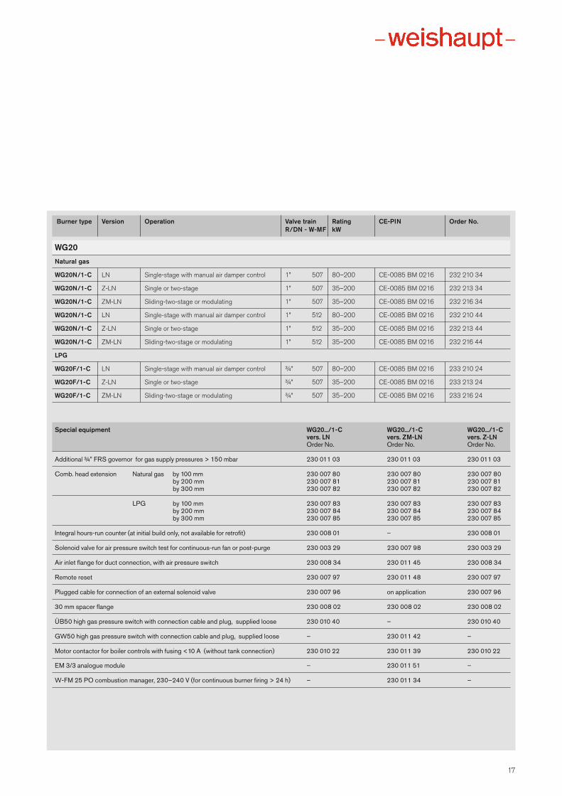
Burner type Version Operation Valve train Rating CE-PIN Order No. R/DN - W-MF kW
WG20Natural gas
WG20N/1-C LN Single-stage with manual air damper control 1” 507 80–200 CE-0085 BM 0216 232 210 34
WG20N/1-C Z-LN Single or two-stage 1” 507 35–200 CE-0085 BM 0216 232 213 34
WG20N/1-C ZM-LN Sliding-two-stage or modulating 1” 507 35–200 CE-0085 BM 0216 232 216 34
WG20N/1-C LN Single-stage with manual air damper control 1” 512 80–200 CE-0085 BM 0216 232 210 44
WG20N/1-C Z-LN Single or two-stage 1” 512 35–200 CE-0085 BM 0216 232 213 44
WG20N/1-C ZM-LN Sliding-two-stage or modulating 1” 512 35–200 CE-0085 BM 0216 232 216 44
LPG
WG20F/1-C LN Single-stage with manual air damper control ¾” 507 80–200 CE-0085 BM 0216 233 210 24
WG20F/1-C Z-LN Single or two-stage ¾” 507 35–200 CE-0085 BM 0216 233 213 24
WG20F/1-C ZM-LN Sliding-two-stage or modulating ¾” 507 35–200 CE-0085 BM 0216 233 216 24
Special equipment WG20.../1-C WG20.../1-C WG20.../1-C vers. LN vers. ZM-LN vers. Z-LN Order No. Order No. Order No.
Additional ¾” FRS governor for gas supply pressures > 150 mbar 230 011 03 230 011 03 230 011 03
Comb. head extension Natural gas by 100 mm 230 007 80 230 007 80 230 007 80 by 200 mm 230 007 81 230 007 81 230 007 81 by 300 mm 230 007 82 230 007 82 230 007 82
LPG by 100 mm 230 007 83 230 007 83 230 007 83 by 200 mm 230 007 84 230 007 84 230 007 84 by 300 mm 230 007 85 230 007 85 230 007 85
Integral hours-run counter (at initial build only, not available for retrofit) 230 008 01 – 230 008 01
Solenoid valve for air pressure switch test for continuous-run fan or post-purge 230 003 29 230 007 98 230 003 29
Air inlet flange for duct connection, with air pressure switch 230 008 34 230 011 45 230 008 34
Remote reset 230 007 97 230 011 48 230 007 97
Plugged cable for connection of an external solenoid valve 230 007 96 on application 230 007 96
30 mm spacer flange 230 008 02 230 008 02 230 008 02
ÜB50 high gas pressure switch with connection cable and plug, supplied loose 230 010 40 – 230 010 40
GW50 high gas pressure switch with connection cable and plug, supplied loose – 230 011 42 –
Motor contactor for boiler controls with fusing <10 A (without tank connection) 230 010 22 230 011 39 230 010 22
EM 3/3 analogue module – 230 011 51 –
W-FM 25 PO combustion manager, 230–240 V (for continuous burner firing > 24 h) – 230 011 34 –
18
WG30 capacity and model overview
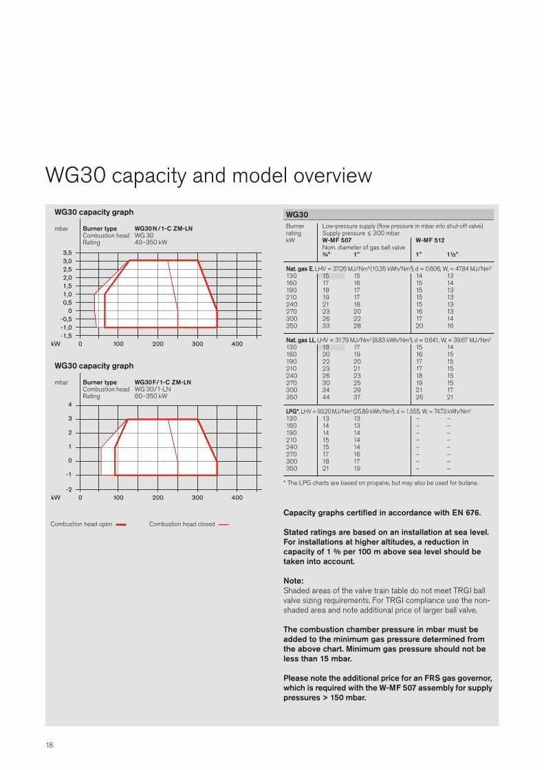
Burner Low-pressure supply (flow pressure in mbar into shut-off valve)rating Supply pressure ≤ 300 mbarkW W-MF 507 W-MF 512 Nom. diameter of gas ball valve ¾” 1” 1” 1½”
Nat. gas E, LHV = 37.26 MJ/Nm3 (10.35 kWh/Nm3), d = 0.606, Wi = 47.84 MJ/Nm3
130 15 15 14 13160 17 16 15 14190 18 17 15 13210 19 17 15 13240 21 18 15 13270 23 20 16 13300 26 22 17 14350 33 28 20 16
Nat. gas LL, LHV = 31.79 MJ/Nm3 (8.83 kWh/Nm3), d = 0.641, Wi = 39.67 MJ/Nm3
130 18 17 15 14160 20 19 16 15190 22 20 17 15210 23 21 17 15240 26 23 18 15270 30 25 19 15300 34 29 21 17350 44 37 26 21
LPG*, LHV = 93.20 MJ/Nm3 (25.89 kWh/Nm3), d = 1.555, Wi = 74.73 kWh/Nm3
130 13 13 – –160 14 13 – –190 14 14 – –210 15 14 – –240 15 14 – –270 17 16 – –300 18 17 – –350 21 19 – –
* The LPG charts are based on propane, but may also be used for butane.
WG30
001 200
-1,0-0,5
-1,5
00,51,01,52,02,53,0
kW 0
3,5
004003
Burner type WG30N/1-C ZM-LNCombustion head WG 30Rating 40–350 kW
mbar
WG30 capacity graph
001 200
-1
-2
0
1
2
3
4
kW 0 004003
Burner type WG30F/1-C ZM-LNCombustion head WG 30/1-LNRating 60–350 kW
mbar
WG30 capacity graph
Capacity graphs certified in accordance with EN 676.
Stated ratings are based on an installation at sea level.For installations at higher altitudes, a reduction in capacity of 1 % per 100 m above sea level should betaken into account.
Note:Shaded areas of the valve train table do not meet TRGI ballvalve sizing requirements. For TRGI compliance use the non-shaded area and note additional price of larger ball valve.
The combustion chamber pressure in mbar must beadded to the minimum gas pressure determined fromthe above chart. Minimum gas pressure should not beless than 15 mbar.
Please note the additional price for an FRS gas governor,which is required with the W-MF 507 assembly for supplypressures > 150 mbar.
Combustion head open Combustion head closed
19
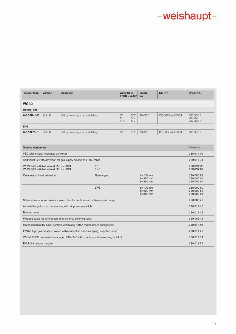
Burner type Version Operation Valve train Rating CE-PIN Order No. R/DN - W-MF kW
WG30Natural gas
WG 30N/1-C ZM-LN Sliding-two-stage or modulating ¾” 507 40–350 CE-0085-AU 0064 232 326 21 1” 512 232 326 31 1½” 512 232 326 51
LPG
WG 30F/1-C ZM-LN Sliding-two-stage or modulating ¾” 507 60–350 CE-0085-AU 0064 233 326 21
Special equipment Order No.
VSD with integral frequency convertor 230 011 49
Additional ¾” FRS governor for gas supply pressures > 150 mbar 230 011 04
W-MF 507 with ball valve & TAE for TRGI 1” 230 010 92W-MF 507 with ball valve & TAE for TRGI 1½” 230 010 93
Combustion head extension Natural gas by 100 mm 230 005 89 by 200 mm 230 005 95
by 300 mm 230 006 04
LPG by 100 mm 230 009 52 by 200 mm 230 009 53 by 300 mm 230 009 54
Solenoid valve for air pressure switch test for continuous-run fan or post-purge 230 005 43
Air inlet flange for duct connection, with air pressure switch 230 011 46
Remote reset 230 011 48
Plugged cable for connection of an external solenoid valve 230 005 45
Motor contactor for boiler controls with fusing <10 A (without tank connection) 230 011 40
GW50 high gas pressure switch with connection cable and plug, supplied loose 230 011 42
W-FM 25 PO combustion manager, 230–240 V (for continuous burner firing > 24 h) 230 011 34
EM 3/3 analogue module 230 011 51
20
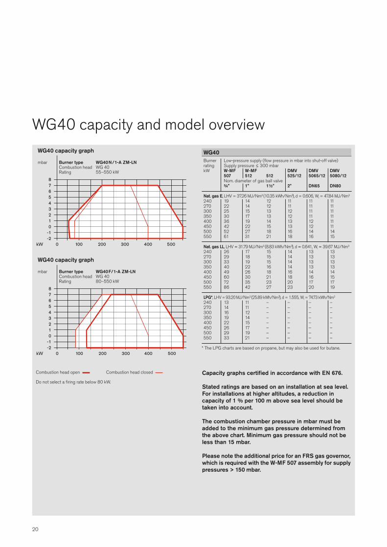
Burner Low-pressure supply (flow pressure in mbar into shut-off valve)rating Supply pressure ≤ 300 mbarkW W-MF W-MF DMV DMV DMV 507 512 512 525/12 5065/12 5080/12 Nom. diameter of gas ball valve ¾” 1” 1½” 2” DN65 DN80
Nat. gas E, LHV = 37.26 MJ/Nm3 (10.35 kWh/Nm3), d = 0.606, Wi = 47.84 MJ/Nm3
240 19 14 12 11 11 11270 22 14 12 11 11 11300 25 15 13 12 11 11350 30 17 13 12 11 11400 36 19 14 13 12 11450 42 22 15 13 12 11500 52 27 18 16 14 14550 61 31 21 18 16 15
Nat. gas LL, LHV = 31.79 MJ/Nm3 (8.83 kWh/Nm3), d = 0.641, Wi = 39.67 MJ/Nm3
240 26 17 15 14 13 13270 29 18 15 14 13 13300 33 19 15 14 13 13350 40 22 16 14 13 13400 49 26 18 16 14 14450 60 30 21 18 16 15500 72 35 23 20 17 17550 86 42 27 23 20 19
LPG*, LHV = 93.20 MJ/Nm3 (25.89 kWh/Nm3), d = 1.555, Wi = 74.73 kWh/Nm3
240 13 11 – – – –270 14 11 – – – –300 16 12 – – – –350 19 14 – – – –400 22 15 – – – –450 26 17 – – – –500 29 19 – – – –550 33 21 – – – –
* The LPG charts are based on propane, but may also be used for butane.
WG40
Capacity graphs certified in accordance with EN 676.
Stated ratings are based on an installation at sea level.For installations at higher altitudes, a reduction in capacity of 1 % per 100 m above sea level should betaken into account.
The combustion chamber pressure in mbar must beadded to the minimum gas pressure determined fromthe above chart. Minimum gas pressure should not beless than 15 mbar.
Please note the additional price for an FRS gas governor,which is required with the W-MF 507 assembly for supplypressures > 150 mbar.
001 200
-10
-2
1234567
kW 0
8
005004003
Burner type WG40N/1-A ZM-LNCombustion head WG 40Rating 55–550 kW
mbar
WG40 capacity graph
0
8
kW 200001
-10
-2
1234567
005004003
Burner type WG40F/1-A ZM-LNCombustion head WG 40Rating 80–550 kW
mbar
WG40 capacity graph
Combustion head open Combustion head closed
Do not select a firing rate below 80 kW.
WG40 capacity and model overview
21
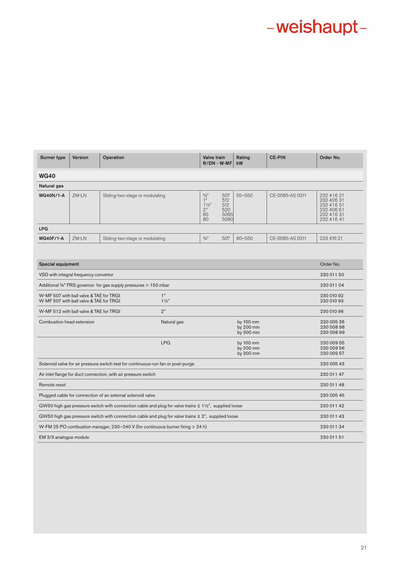
Burner type Version Operation Valve train Rating CE-PIN Order No. R/DN - W-MF kW
WG40Natural gas
WG40N/1-A ZM-LN Sliding-two-stage or modulating ¾” 507 55–550 CE-0085-AS 0311 232 416 21 1” 512 232 426 31 1½” 512 232 416 51 2” 520 232 406 61 65 5065 232 416 31 80 5080 232 416 41
LPG
WG40F/1-A ZM-LN Sliding-two-stage or modulating ¾” 507 80–550 CE-0085-AS 0311 233 416 21
Special equipment Order No.
VSD with integral frequency convertor 230 011 50
Additional ¾” FRS governor for gas supply pressures > 150 mbar 230 011 04
W-MF 507 with ball valve & TAE for TRGI 1” 230 010 92W-MF 507 with ball valve & TAE for TRGI 1½” 230 010 93
W-MF 512 with ball valve & TAE for TRGI 2” 230 010 96
Combustion head extension Natural gas by 100 mm 230 005 36 by 200 mm 230 008 98
by 300 mm 230 008 99
LPG by 100 mm 230 009 55 by 200 mm 230 009 56 by 300 mm 230 009 57
Solenoid valve for air pressure switch test for continuous-run fan or post-purge 230 005 43
Air inlet flange for duct connection, with air pressure switch 230 011 47
Remote reset 230 011 48
Plugged cable for connection of an external solenoid valve 230 005 45
GW50 high gas pressure switch with connection cable and plug for valve trains ≤ 1½”, supplied loose 230 011 42
GW50 high gas pressure switch with connection cable and plug for valve trains ≥ 2”, supplied loose 230 011 43
W-FM 25 PO combustion manager, 230–240 V (for continuous burner firing > 24 h) 230 011 34
EM 3/3 analogue module 230 011 51
22
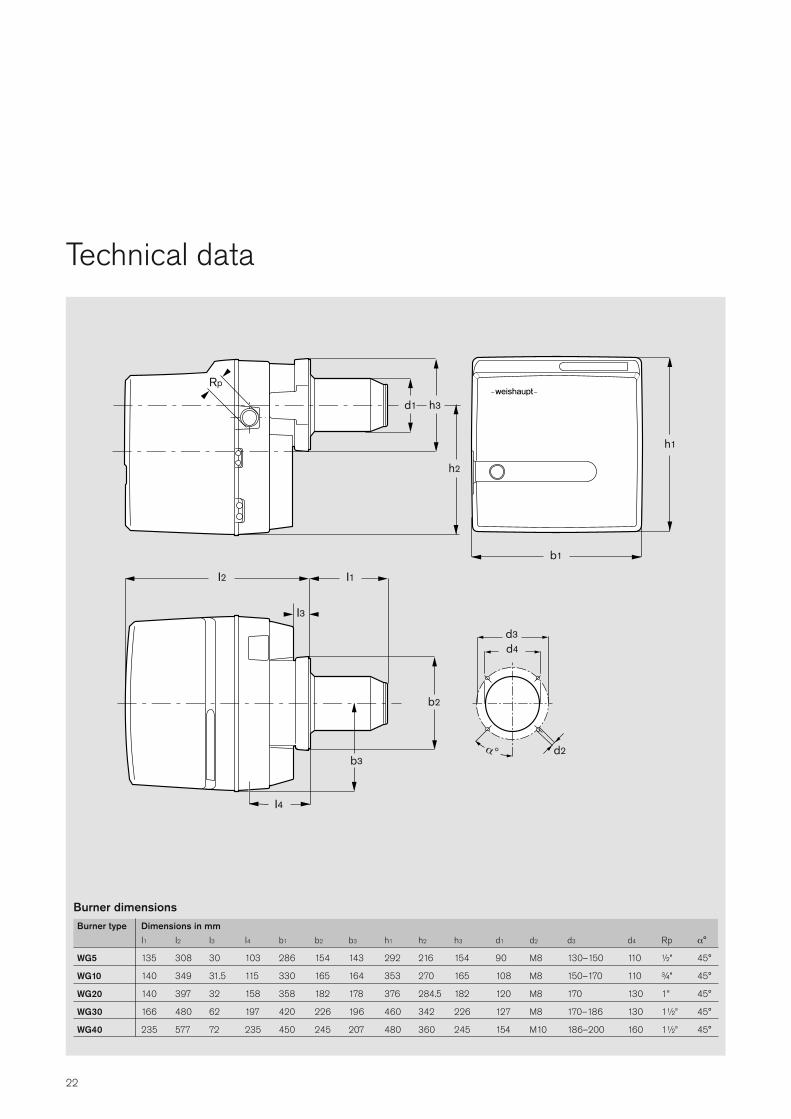
Technical data
d1 h3
b1
h1
I2 I1
b2
b3
I3
I4
d3d4
d2
h2
Rp
Burner dimensionsBurner type Dimensions in mm I1 I2 I3 I4 b1 b2 b3 h1 h2 h3 d1 d2 d3 d4 Rp α°
WG5 135 308 30 103 286 154 143 292 216 154 90 M8 130–150 110 ½” 45°
WG10 140 349 31.5 115 330 165 164 353 270 165 108 M8 150–170 110 ¾” 45°
WG20 140 397 32 158 358 182 178 376 284.5 182 120 M8 170 130 1” 45°
WG30 166 480 62 197 420 226 196 460 342 226 127 M8 170–186 130 1½” 45°
WG40 235 577 72 235 450 245 207 480 360 245 154 M10 186–200 160 1½” 45°
23
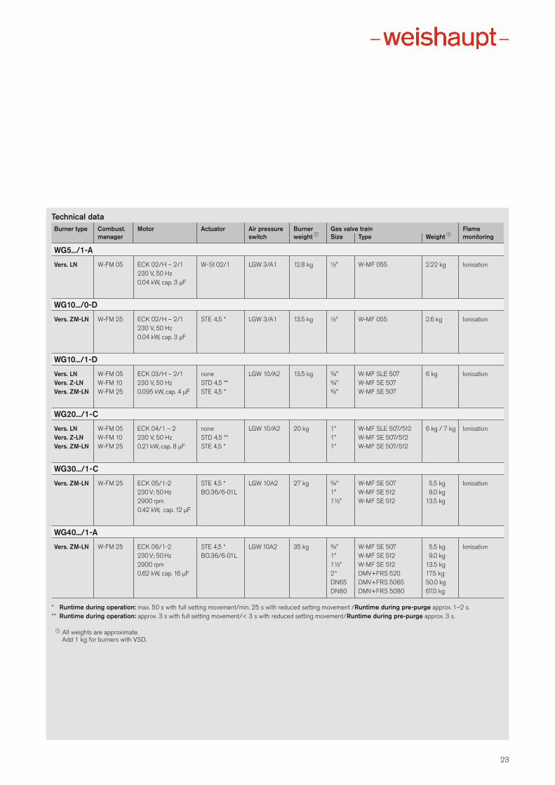
Technical dataBurner type Combust. Motor Actuator Air pressure Burner Gas valve train Flame manager switch weight 1 Size Type Weight 1 monitoring
WG5.../1-A
Vers. LN W-FM 05 ECK 02/H – 2/1 W-St 02/1 LGW 3/A1 12.8 kg ½” W-MF 055 2.22 kg Ionisation 230 V, 50 Hz 0.04 kW, cap. 3 μF
WG10.../0-D
Vers. ZM-LN W-FM 25 ECK 02/H – 2/1 STE 4,5 * LGW 3/A1 13.5 kg ½” W-MF 055 2.6 kg Ionisation 230 V, 50 Hz 0.04 kW, cap. 3 μF
WG10.../1-D
Vers. LN W-FM 05 ECK 03/H – 2/1 none LGW 10/A2 13.5 kg ¾” W-MF SLE 507 6 kg IonisationVers. Z-LN W-FM 10 230 V, 50 Hz STD 4,5 ** ¾” W-MF SE 507Vers. ZM-LN W-FM 25 0.095 kW, cap. 4 μF STE 4,5 * ¾” W-MF SE 507
WG20.../1-C
Vers. LN W-FM 05 ECK 04/1 – 2 none LGW 10/A2 20 kg 1” W-MF SLE 507/512 6 kg / 7 kg IonisationVers. Z-LN W-FM 10 230 V, 50 Hz STD 4,5 ** 1” W-MF SE 507/512 Vers. ZM-LN W-FM 25 0.21 kW, cap. 8 μF STE 4,5 * 1” W-MF SE 507/512
WG30.../1-C
Vers. ZM-LN W-FM 25 ECK 05/1-2 STE 4,5 * LGW 10A2 27 kg ¾” W-MF SE 507 5.5 kg Ionisation 230 V; 50 Hz BO.36/6-01L 1” W-MF SE 512 9.0 kg 2900 rpm 1½” W-MF SE 512 13.5 kg 0.42 kW, cap. 12 μF
WG40.../1-A
Vers. ZM-LN W-FM 25 ECK 06/1-2 STE 4,5 * LGW 10A2 35 kg ¾” W-MF SE 507 5.5 kg Ionisation 230 V; 50 Hz BO.36/6-01L 1” W-MF SE 512 9.0 kg 2900 rpm 1½” W-MF SE 512 13.5 kg 0.62 kW, cap. 16 μF 2” DMV+FRS 520 17.5 kg DN65 DMV+FRS 5065 50.0 kg DN80 DMV+FRS 5080 67.0 kg
* Runtime during operation: max. 50 s with full setting movement/min. 25 s with reduced setting movement /Runtime during pre-purge approx. 1–2 s.** Runtime during operation: approx. 3 s with full setting movement/< 3 s with reduced setting movement/Runtime during pre-purge approx. 3 s.
1 All weights are approximate.Add 1 kg for burners with VSD.
We’re right where you need us
Max Weis haupt GmbH88475 Schwen diTe l +49 7353 830 Fax +49 7353 83358www.weis haupt.de
Print No. 83214102, January 2015Printed in Germany. All rights reserved.
Neachells Lane, Willenhall, WV13 3RGTel (01902) 609841 Fax (01902) 633343
The security of a comprehensiveservice networkWeishaupt equipment is available fromgood HVAC specialists, with whomWeishaupt works in close partnership.To support the specialists, Weishauptmaintains a large sales and service network, ensuring equipment, sparesand service are always available.
Weishaupt are there when you needthem. The service department is available to Weishaupt customers around the clock, 365 days a year. AWeishaupt office near you is standingby to answer all your heating questions.