Embed Size (px)
Citation preview

—C ATALOG
Steel City®Commercial fittings

— Thomas & Betts is now ABBInstallation Products, but our longlegacy of quality products andinnovation remains the same. Fromconnectors that help wire buildingson Earth to cable ties that help putmachines in space, we continue towork every day to make, market,design and sell products thatprovide a smarter, safer and morereliable flow of electricity, fromsource to socket.
— Table of contents
004– 005 Overview
006– 011 Electrical metallic tubing (EMT) fittings
012– 020 Rigid conduit/IMC fittings
021– 022 Non-metallic sheathed cable fittings
023– 028 Armored cable/flexible metallic conduit fittings
029– 032 Accessories
033– 035 Liquidtight flexible metallic conduit fittings: Zinc die cast
036– 042 Index
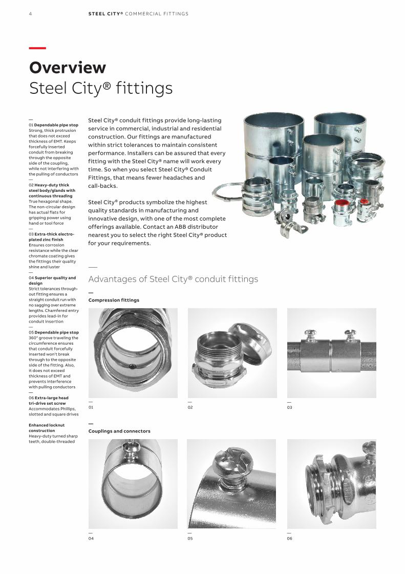
Steel City® conduit fittings provide long-lasting service in commercial, industrial and residential construction. Our fittings are manufacturedwithin strict tolerances to maintain consistent performance. Installers can be assured that every fitting with the Steel City® name will work every time. So when you select Steel City® Conduit Fittings, that means fewer headaches and call-backs.
Steel City® products symbolize the highest quality standards in manufacturing and innovative design, with one of the most completeofferings available. Contact an ABB distributor nearest you to select the right Steel City® product for your requirements.
—OverviewSteel City® fittings
—01 Dependable pipe stopStrong, thick protrusion that does not exceedthickness of EMT. Keeps forcefully insertedconduit from breaking through the oppositeside of the coupling, while not interfering withthe pulling of conductors—02 Heavy-duty thick steel body/glands with continuous threadingTrue hexagonal shape. The non-circular design has actual flats for gripping power using hand or tool force—03 Extra-thick electro-plated zinc finishEnsures corrosion resistance while the clearchromate coating gives the fittings their quality shine and luster—04 Superior quality and designStrict tolerances through-out fitting ensures a straight conduit run withno sagging over extreme lengths. Chamfered entryprovides lead-in forconduit insertion—05 Dependable pipe stop360° groove traveling the circumference ensures that conduit forcefullyinserted won’t break through to the opposite side of the fitting. Also, it does not exceed thickness of EMT and prevents interferencewith pulling conductors—06 Extra-large head tri-drive set screwAccommodates Phillips, slotted and square drives
Enhanced locknut constructionHeavy-duty turned sharpteeth, double-threaded
—01
—02
—03
—04
—05
—06
—Advantages of Steel City® conduit fittings
4 S TE E L CIT Y® CO M M ER CI A L FIT TI N G S
—Compression fittings
—Couplings and connectors
OV ER V I E W
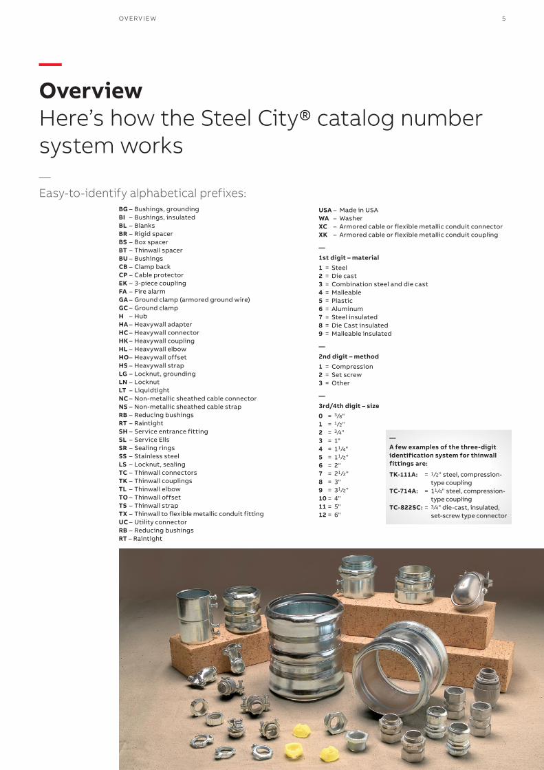
USA – Made in USAWA – WasherXC – Armored cable or flexible metallic conduit connectorXK – Armored cable or flexible metallic conduit coupling
—1st digit – material1 = Steel2 = Die cast3 = Combination steel and die cast4 = Malleable5 = Plastic6 = Aluminum7 = Steel insulated8 = Die Cast insulated9 = Malleable insulated
—2nd digit – method1 = Compression2 = Set screw3 = Other
—3rd/4th digit – size0 = 3 ⁄8"1 = 1 ⁄2"2 = 3 ⁄4"3 = 1"4 = 11 ⁄4"5 = 11 ⁄2"6 = 2"7 = 21 ⁄2"8 = 3"9 = 31 ⁄2"10 = 4"11 = 5"12 = 6"
—OverviewHere’s how the Steel City® catalog number system works—Easy-to-identify alphabetical prefixes:
—A few examples of the three-digit identification system for thinwall fittings are:
TK-111A: = 1 ⁄2" steel, compression- type couplingTC-714A: = 11 ⁄4" steel, compression- type couplingTC-822SC: = 3 ⁄4" die-cast, insulated, set-screw type connector
5
BG – Bushings, groundingBI – Bushings, insulatedBL – BlanksBR – Rigid spacerBS – Box spacerBT – Thinwall spacerBU – BushingsCB – Clamp backCP – Cable protectorEK – 3-piece couplingFA – Fire alarmGA – Ground clamp (armored ground wire)GC – Ground clampH – HubHA – Heavywall adapterHC – Heavywall connectorHK – Heavywall couplingHL – Heavywall elbowHO – Heavywall offsetHS – Heavywall strapLG – Locknut, groundingLN – LocknutLT – LiquidtightNC – Non-metallic sheathed cable connectorNS – Non-metallic sheathed cable strapRB – Reducing bushingsRT – RaintightSH – Service entrance fittingSL – Service EllsSR – Sealing ringsSS – Stainless steelLS – Locknut, sealingTC – Thinwall connectorsTK – Thinwall couplingsTL – Thinwall elbowTO – Thinwall offsetTS – Thinwall strapTX – Thinwall to flexible metallic conduit fitting UC – Utility connectorRB – Reducing bushingsRT – Raintight
6 S TE E L CIT Y® CO M M ER CI A L FIT TI N G S
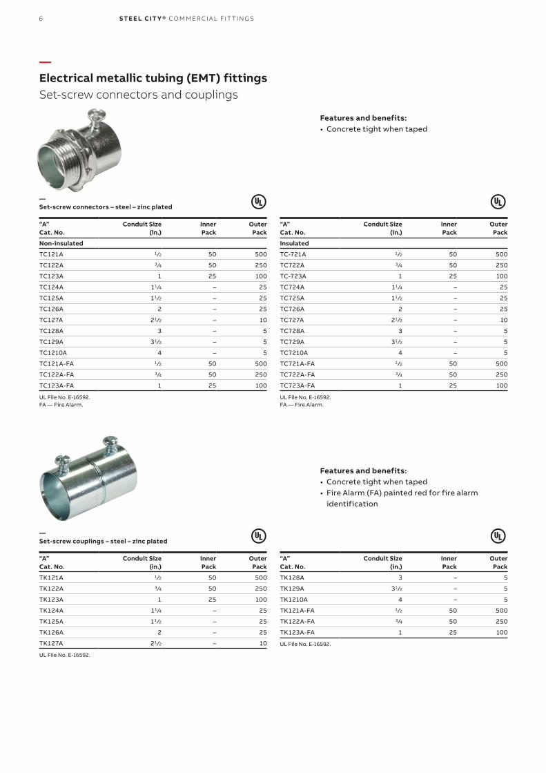
—Electrical metallic tubing (EMT) fittingsSet-screw connectors and couplings
Features and benefits:• Concrete tight when taped
Features and benefits:• Concrete tight when taped• Fire Alarm (FA) painted red for fire alarm
identification
“A” Cat. No.
Conduit Size (in.)
Inner Pack
Outer Pack
Non-insulated
TC121A 1 ⁄2 50 500
TC122A 3 ⁄4 50 250
TC123A 1 25 100
TC124A 11 ⁄4 – 25
TC125A 11 ⁄2 – 25
TC126A 2 – 25
TC127A 21 ⁄2 – 10
TC128A 3 – 5
TC129A 31 ⁄2 – 5
TC1210A 4 – 5
TC121A-FA 1 ⁄2 50 500
TC122A-FA 3 ⁄4 50 250
TC123A-FA 1 25 100
UL File No. E-16592.FA — Fire Alarm.
“A” Cat. No.
Conduit Size (in.)
Inner Pack
Outer Pack
TK121A 1 ⁄2 50 500
TK122A 3 ⁄4 50 250
TK123A 1 25 100
TK124A 11 ⁄4 – 25
TK125A 11 ⁄2 – 25
TK126A 2 – 25
TK127A 21 ⁄2 – 10
UL File No. E-16592.
“A” Cat. No.
Conduit Size (in.)
Inner Pack
Outer Pack
Insulated
TC-721A 1 ⁄2 50 500
TC722A 3 ⁄4 50 250
TC-723A 1 25 100
TC724A 11 ⁄4 – 25
TC725A 11 ⁄2 – 25
TC726A 2 – 25
TC727A 21 ⁄2 – 10
TC728A 3 – 5
TC729A 31 ⁄2 – 5
TC7210A 4 – 5
TC721A-FA 1 ⁄2 50 500
TC722A-FA 3 ⁄4 50 250
TC723A-FA 1 25 100
UL File No. E-16592.FA — Fire Alarm.
“A” Cat. No.
Conduit Size (in.)
Inner Pack
Outer Pack
TK128A 3 – 5
TK129A 31 ⁄2 – 5
TK1210A 4 – 5
TK121A-FA 1 ⁄2 50 500
TK122A-FA 3 ⁄4 50 250
TK123A-FA 1 25 100
UL File No. E-16592.
—Set-screw connectors – steel – zinc plated
—Set-screw couplings – steel – zinc plated
EL EC TR I C A L M E TA L L I C T U B I N G (EMT ) FIT TI N G S 7
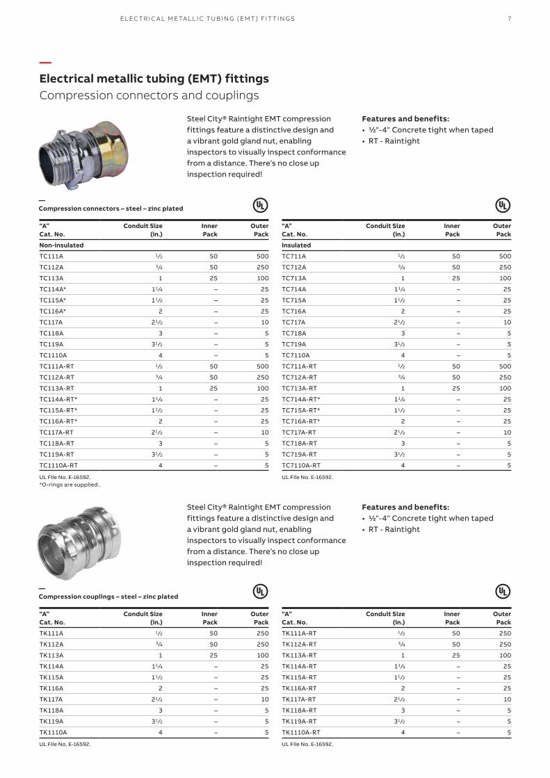
—Electrical metallic tubing (EMT) fittingsCompression connectors and couplings
Features and benefits:• ½"-4" Concrete tight when taped• RT - Raintight
Features and benefits:• ½"-4" Concrete tight when taped• RT - Raintight
“A” Cat. No.
Conduit Size (in.)
Inner Pack
Outer Pack
Non-insulated
TC111A 1 ⁄2 50 500
TC112A 3 ⁄4 50 250
TC113A 1 25 100
TC114A* 11 ⁄4 – 25
TC115A* 11 ⁄2 – 25
TC116A* 2 – 25
TC117A 21 ⁄2 – 10
TC118A 3 – 5
TC119A 31 ⁄2 – 5
TC1110A 4 – 5
TC111A-RT 1 ⁄2 50 500
TC112A-RT 3 ⁄4 50 250
TC113A-RT 1 25 100
TC114A-RT* 11 ⁄4 – 25
TC115A-RT* 11 ⁄2 – 25
TC116A-RT* 2 – 25
TC117A-RT 21 ⁄2 – 10
TC118A-RT 3 – 5
TC119A-RT 31 ⁄2 – 5
TC1110A-RT 4 – 5
UL File No. E-16592.*O-rings are supplied..
“A” Cat. No.
Conduit Size (in.)
Inner Pack
Outer Pack
TK111A 1 ⁄2 50 250
TK112A 3 ⁄4 50 250
TK113A 1 25 100
TK114A 11 ⁄4 – 25
TK115A 11 ⁄2 – 25
TK116A 2 – 25
TK117A 21 ⁄2 – 10
TK118A 3 – 5
TK119A 31 ⁄2 – 5
TK1110A 4 – 5
UL File No. E-16592.
“A” Cat. No.
Conduit Size (in.)
Inner Pack
Outer Pack
Insulated
TC711A 1 ⁄2 50 500
TC712A 3 ⁄4 50 250
TC713A 1 25 100
TC714A 11 ⁄4 – 25
TC715A 11 ⁄2 – 25
TC716A 2 – 25
TC717A 21 ⁄2 – 10
TC718A 3 – 5
TC719A 31 ⁄2 – 5
TC7110A 4 – 5
TC711A-RT 1 ⁄2 50 500
TC712A-RT 3 ⁄4 50 250
TC713A-RT 1 25 100
TC714A-RT* 11 ⁄4 – 25
TC715A-RT* 11 ⁄2 – 25
TC716A-RT* 2 – 25
TC717A-RT 21 ⁄2 – 10
TC718A-RT 3 – 5
TC719A-RT 31 ⁄2 – 5
TC7110A-RT 4 – 5
UL File No. E-16592.
“A” Cat. No.
Conduit Size (in.)
Inner Pack
Outer Pack
TK111A-RT 1 ⁄2 50 250
TK112A-RT 3 ⁄4 50 250
TK113A-RT 1 25 100
TK114A-RT 11 ⁄4 – 25
TK115A-RT 11 ⁄2 – 25
TK116A-RT 2 – 25
TK117A-RT 21 ⁄2 – 10
TK118A-RT 3 – 5
TK119A-RT 31 ⁄2 – 5
TK1110A-RT 4 – 5
UL File No. E-16592.
—Compression connectors – steel – zinc plated
—Compression couplings – steel – zinc plated
Steel City® Raintight EMT compression fittings feature a distinctive design and a vibrant gold gland nut, enabling inspectors to visually inspect conformance from a distance. There’s no close up inspection required!
Steel City® Raintight EMT compression fittings feature a distinctive design and a vibrant gold gland nut, enabling inspectors to visually inspect conformance from a distance. There’s no close up inspection required!
8 S TE E L CIT Y® CO M M ER CI A L FIT TI N G S
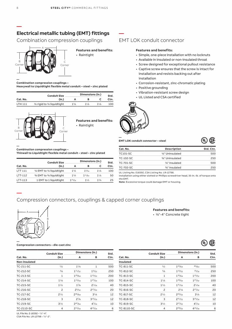
—Electrical metallic tubing (EMT) fittingsCombination compression couplings
—EMT LOK conduit connector
Features and benefits:• Raintight
Features and benefits:• Raintight
Features and benefits:• Simple, one-piece installation with no locknuts• Available in insulated or non-insulated throat• Screw designed for exceptional pullout resistance• Captive screw ensures that the screw is intact for
installation and resists backing out after installation
• Corrosion-resistant, zinc-chromatic plating• Positive grounding• Vibration-resistant screw design• UL Listed and CSA certifiedConduit Size
(in.)
Dimensions (in.) Std.Ctn.Cat. No. A B C
LTH 111 ½ rigid to ½ liquidtight 17⁄8 11 ⁄8 11 ⁄8 100
Conduit Size (in.)
Dimensions (in.) Std.Ctn.Cat. No. A B C
LTT 111 ½ EMT to ½ liquidtight 13 ⁄4 15 ⁄16 11 ⁄8 100
LTT-112 ¾ EMT to ¾ liquidtight 13 ⁄4 111 ⁄64 11 ⁄8 50
LTT-113 1 EMT to 1 liquidtight 115 ⁄16 11 ⁄2 13 ⁄4 25
Cat. No. Description Std. Ctn.
TC101-SC ½" Uninsulated 500
TC-102-SC ¾" Uninsulated 250
TC-701-SC ½" Insulated 500
TC-702-SC ¾" Insulated 250
UL Listing No. E16592, CSA Listing No. LR-12798.Installation using either slotted or Phillips screwdriver head, 35-in.-lb. of torque onto the EMT.Note: Excessive torque could damage EMT or housing.
—Combination compression couplings – Heavywall to Liquidtight flexible metal conduit – steel – zinc plated
—Combination compression couplings – Thinwall to Liquidtight flexible metal conduit – steel – zinc plated
—EMT LOK conduit connector – steel
A
C Corner
B Corner
A
C Corner
B Corner
—Compression connectors, couplings & capped corner couplings
Features and benefits:• ½"-4" Concrete tight
Conduit Size(in.)
Dimensions (in.) Std.Ctn.Cat. No. A B
Non-insulated
TC-211-SC 1 ⁄2 11 ⁄4 1 500
TC-212-SC 3 ⁄4 111 ⁄32 15 ⁄32 250
TC-213-SC 1 129 ⁄64 115 ⁄32 200
TC-214-SC 11 ⁄4 113 ⁄16 127⁄32 100
TC-215-SC 11 ⁄2 17⁄8 21 ⁄16 40
TC-216-SC 2 25 ⁄32 217⁄32 20
TC-217-SC 21 ⁄2 245 ⁄64 31 ⁄4 12
TC-218-SC 3 27⁄8 315 ⁄16 12
TC-219-SC 31 ⁄2 247⁄64 47⁄16 10
TC-2110-SC 4 213 ⁄16 415 ⁄16 6
UL File No. E-16592 – 1 ⁄2"-4".CSA File No. LR-12798 – 1 ⁄2"-2".
Conduit Size(in.)
Dimensions (in.) Std.Ctn.Cat. No. A B
Insulated
TC-811-SC 1 ⁄2 123 ⁄64 63 ⁄64 500
TC-812-SC 3 ⁄4 115 ⁄32 15 ⁄16 250
TC-813-SC 1 135 ⁄64 115 ⁄32 200
TC-814-SC 11 ⁄4 129 ⁄32 127⁄32 100
TC-815-SC 11 ⁄2 131 ⁄32 21 ⁄16 40
TC-816-SC 2 21 ⁄4 217⁄32 20
TC-817-SC 21 ⁄2 225 ⁄32 31 ⁄4 12
TC-818-SC 3 231 ⁄32 315 ⁄16 12
TC-819-SC 31 ⁄2 227⁄32 47⁄16 10
TC-8110-SC 4 229 ⁄32 415 ⁄16 6
—Compression connectors – die-cast zinc
A
B
9EL EC TR I C A L M E TA L L I C T U B I N G (EMT ) FIT TI N G S
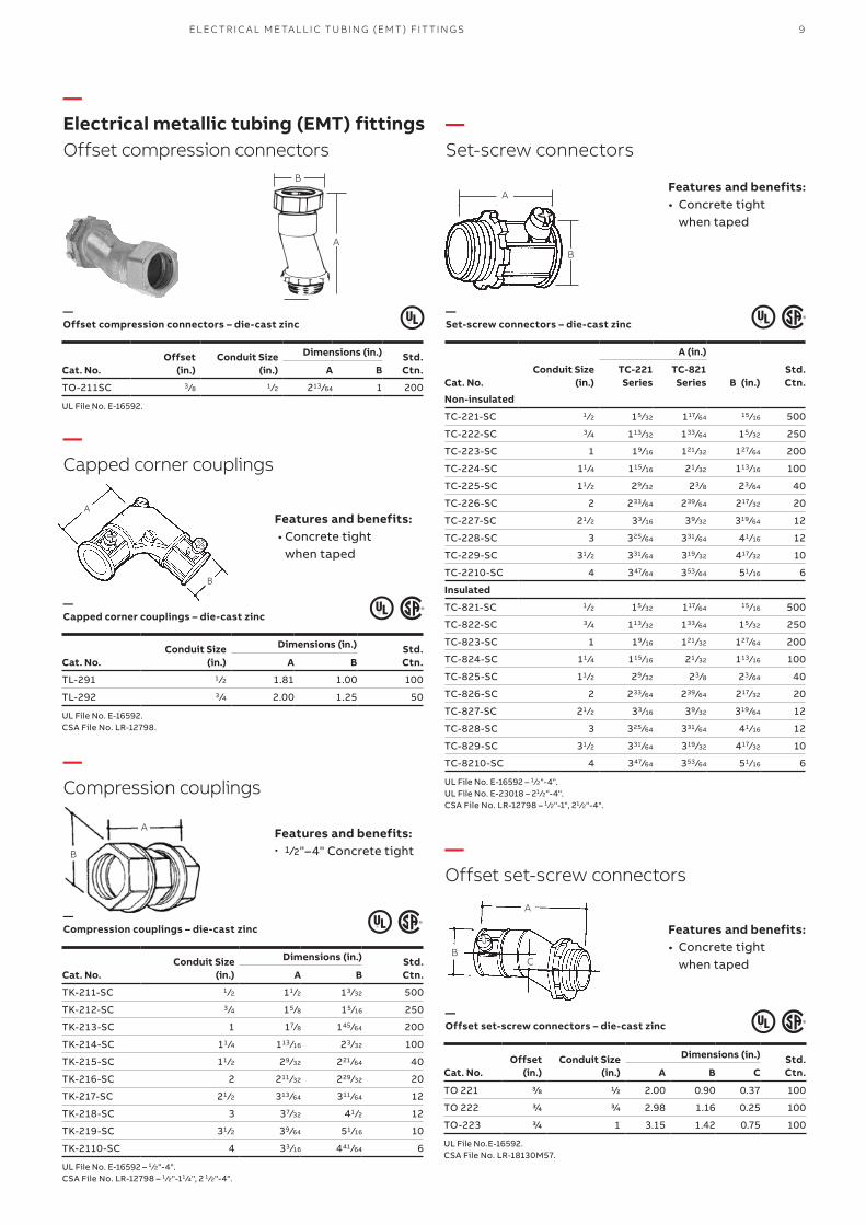
—Electrical metallic tubing (EMT) fittingsOffset compression connectors
Offset(in.)
Conduit Size(in.)
Dimensions (in.) Std.Ctn.Cat. No. A B
TO-211SC 3 ⁄8 1 ⁄2 213 ⁄64 1 200
UL File No. E-16592.
Conduit Size(in.)
Dimensions (in.) Std.Ctn.Cat. No. A B
TL-291 1 ⁄2 1.81 1.00 100
TL-292 3 ⁄4 2.00 1.25 50
UL File No. E-16592.CSA File No. LR-12798.
Conduit Size(in.)
Dimensions (in.) Std.Ctn.Cat. No. A B
TK-211-SC 1 ⁄2 11 ⁄2 13 ⁄32 500
TK-212-SC 3 ⁄4 15 ⁄8 15 ⁄16 250
TK-213-SC 1 17⁄8 145 ⁄64 200
TK-214-SC 11 ⁄4 113 ⁄16 23 ⁄32 100
TK-215-SC 11 ⁄2 29 ⁄32 221 ⁄64 40
TK-216-SC 2 211 ⁄32 229 ⁄32 20
TK-217-SC 21 ⁄2 313 ⁄64 311 ⁄64 12
TK-218-SC 3 37⁄32 41 ⁄2 12
TK-219-SC 31 ⁄2 39 ⁄64 51 ⁄16 10
TK-2110-SC 4 33 ⁄16 441 ⁄64 6
UL File No. E-16592 – 1 ⁄2"-4".CSA File No. LR-12798 – 1 ⁄2"-11 ⁄4", 2 1 ⁄2"-4".
—Compression couplings – die-cast zinc
—Offset compression connectors – die-cast zinc
—Capped corner couplings – die-cast zinc
A
B
A
B
—Compression couplings
—Offset set-screw connectors
—Capped corner couplings
A
B
—Set-screw connectors
Features and benefits:• Concrete tight
when taped
Features and benefits:• Concrete tight
when taped
Features and benefits:• Concrete tight
when taped
Features and benefits:• 1 ⁄2"–4" Concrete tight
Cat. No.
Conduit Size(in.)
A (in.)
B (in.)Std.Ctn.
TC-221Series
TC-821Series
Non-insulated
TC-221-SC 1 ⁄2 15 ⁄32 117⁄64 15 ⁄16 500
TC-222-SC 3 ⁄4 113 ⁄32 133 ⁄64 15 ⁄32 250
TC-223-SC 1 19 ⁄16 121 ⁄32 127⁄64 200
TC-224-SC 11 ⁄4 115 ⁄16 21 ⁄32 113 ⁄16 100
TC-225-SC 11 ⁄2 29 ⁄32 23 ⁄8 23 ⁄64 40
TC-226-SC 2 233 ⁄64 239 ⁄64 217⁄32 20
TC-227-SC 21 ⁄2 33 ⁄16 39 ⁄32 319 ⁄64 12
TC-228-SC 3 325 ⁄64 331 ⁄64 41 ⁄16 12
TC-229-SC 31 ⁄2 331 ⁄64 319 ⁄32 417⁄32 10
TC-2210-SC 4 347⁄64 353 ⁄64 51 ⁄16 6
Insulated
TC-821-SC 1 ⁄2 15 ⁄32 117⁄64 15 ⁄16 500
TC-822-SC 3 ⁄4 113 ⁄32 133 ⁄64 15 ⁄32 250
TC-823-SC 1 19 ⁄16 121 ⁄32 127⁄64 200
TC-824-SC 11 ⁄4 115 ⁄16 21 ⁄32 113 ⁄16 100
TC-825-SC 11 ⁄2 29 ⁄32 23 ⁄8 23 ⁄64 40
TC-826-SC 2 233 ⁄64 239 ⁄64 217⁄32 20
TC-827-SC 21 ⁄2 33 ⁄16 39 ⁄32 319 ⁄64 12
TC-828-SC 3 325 ⁄64 331 ⁄64 41 ⁄16 12
TC-829-SC 31 ⁄2 331 ⁄64 319 ⁄32 417⁄32 10
TC-8210-SC 4 347⁄64 353 ⁄64 51 ⁄16 6
UL File No. E-16592 – 1 ⁄2"-4".UL File No. E-23018 – 21 ⁄2"-4".CSA File No. LR-12798 – 1 ⁄2"-1", 21 ⁄2"-4".
—Set-screw connectors – die-cast zinc
A
B
Offset (in.)
Conduit Size (in.)
Dimensions (in.) Std.Ctn.Cat. No. A B C
TO 221 ⅜ ½ 2.00 0.90 0.37 100
TO 222 ¾ ¾ 2.98 1.16 0.25 100
TO-223 ¾ 1 3.15 1.42 0.75 100
UL File No.E-16592.CSA File No. LR-18130M57.
—Offset set-screw connectors – die-cast zinc
A
BC
10 S TE E L CIT Y® CO M M ER CI A L FIT TI N G S
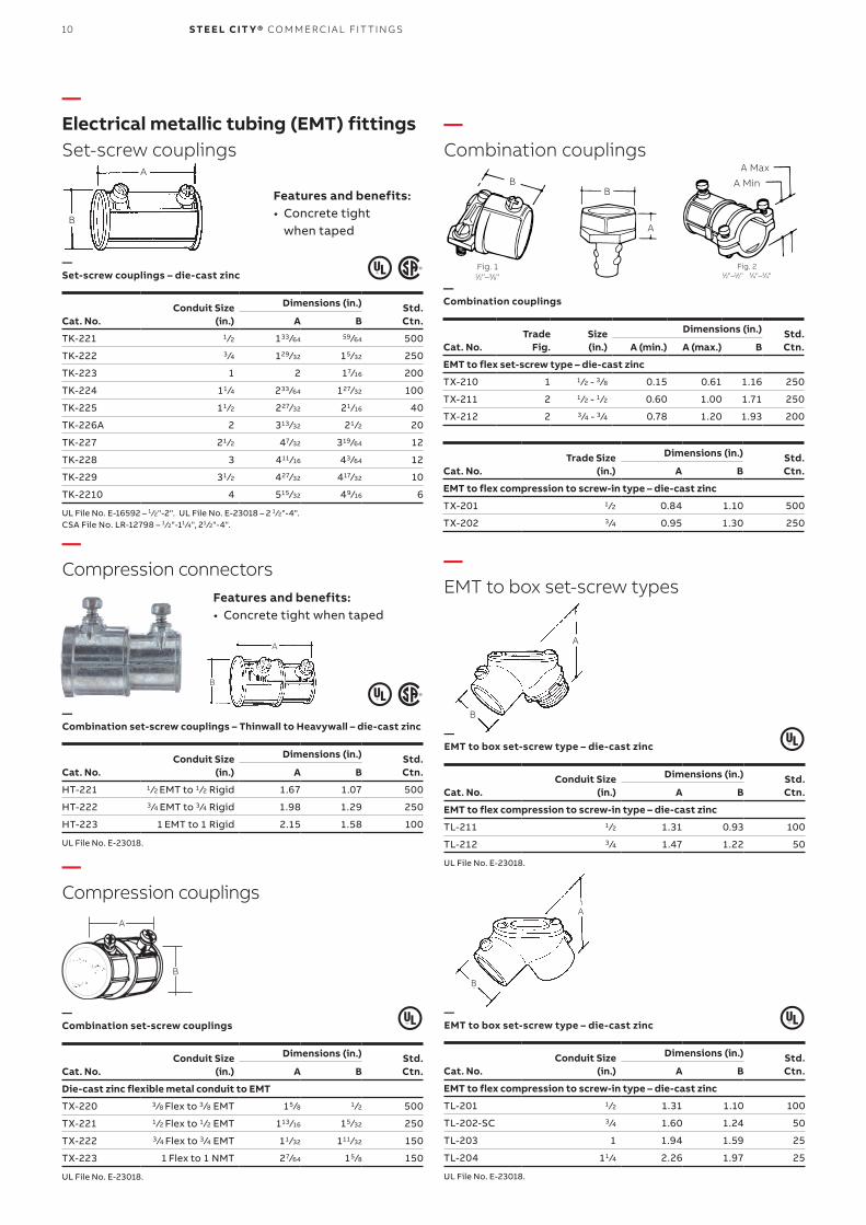
—Electrical metallic tubing (EMT) fittingsSet-screw couplings
Features and benefits:• Concrete tight
when taped
Features and benefits:• Concrete tight when taped
—Set-screw couplings – die-cast zinc
—Combination set-screw couplings – Thinwall to Heavywall – die-cast zinc
A
B
Conduit Size(in.)
Dimensions (in.) Std.Ctn.Cat. No. A B
TK-221 1 ⁄2 133 ⁄64 59 ⁄64 500
TK-222 3 ⁄4 129 ⁄32 15 ⁄32 250
TK-223 1 2 17⁄16 200
TK-224 11 ⁄4 233 ⁄64 127⁄32 100
TK-225 11 ⁄2 227⁄32 21 ⁄16 40
TK-226A 2 313 ⁄32 21 ⁄2 20
TK-227 21 ⁄2 47⁄32 319 ⁄64 12
TK-228 3 411 ⁄16 43 ⁄64 12
TK-229 31 ⁄2 427⁄32 417⁄32 10
TK-2210 4 515 ⁄32 49 ⁄16 6
UL File No. E-16592 – 1 ⁄2"-2". UL File No. E-23018 – 2 1 ⁄2"-4".CSA File No. LR-12798 – 1 ⁄2"-11 ⁄4", 21 ⁄2"-4".
Conduit Size(in.)
Dimensions (in.) Std.Ctn.Cat. No. A B
HT-221 1 ⁄2 EMT to 1 ⁄2 Rigid 1.67 1.07 500
HT-222 3 ⁄4 EMT to 3 ⁄4 Rigid 1.98 1.29 250
HT-223 1 EMT to 1 Rigid 2.15 1.58 100
UL File No. E-23018.
Conduit Size(in.)
Dimensions (in.) Std.Ctn.Cat. No. A B
Die-cast zinc flexible metal conduit to EMT
TX-220 3 ⁄8 Flex to 3 ⁄8 EMT 15 ⁄8 1 ⁄2 500
TX-221 1 ⁄2 Flex to 1 ⁄2 EMT 113 ⁄16 15 ⁄32 250
TX-222 3 ⁄4 Flex to 3 ⁄4 EMT 11 ⁄32 111 ⁄32 150
TX-223 1 Flex to 1 NMT 27⁄64 15 ⁄8 150
UL File No. E-23018.
Conduit Size(in.)
Dimensions (in.) Std.Ctn.Cat. No. A B
EMT to flex compression to screw-in type – die-cast zinc
TL-211 1 ⁄2 1.31 0.93 100
TL-212 3 ⁄4 1.47 1.22 50
UL File No. E-23018.
Conduit Size(in.)
Dimensions (in.) Std.Ctn.Cat. No. A B
EMT to flex compression to screw-in type – die-cast zinc
TL-201 1 ⁄2 1.31 1.10 100
TL-202-SC 3 ⁄4 1.60 1.24 50
TL-203 1 1.94 1.59 25
TL-204 11 ⁄4 2.26 1.97 25
UL File No. E-23018.
Trade Size(in.)
Dimensions (in.) Std.Ctn.Cat. No. A B
EMT to flex compression to screw-in type – die-cast zinc
TX-201 1 ⁄2 0.84 1.10 500
TX-202 3 ⁄4 0.95 1.30 250
Trade Fig.
Size(in.)
Dimensions (in.) Std.Ctn.Cat. No. A (min.) A (max.) B
EMT to flex set-screw type – die-cast zinc
TX-210 1 1 ⁄2 - 3 ⁄8 0.15 0.61 1.16 250
TX-211 2 1 ⁄2 - 1 ⁄2 0.60 1.00 1.71 250
TX-212 2 3 ⁄4 - 3 ⁄4 0.78 1.20 1.93 200
A
B
A
B
—Combination set-screw couplings
—EMT to box set-screw type – die-cast zinc
—EMT to box set-screw type – die-cast zinc
—Combination couplings
Fig. 1
1⁄2"–3⁄8"Fig. 2
1⁄2"–1⁄2" 3⁄4"–3⁄4"
A
B
A
BB
A Max
A Min
A
B
A
B
—Compression connectors
—Compression couplings
—Combination couplings
—EMT to box set-screw types
11EL EC TR I C A L M E TA L L I C T U B I N G (EMT ) FIT TI N G S
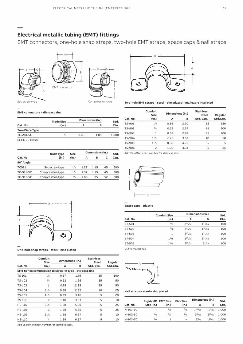
—Electrical metallic tubing (EMT) fittingsEMT connectors, one-hole snap straps, two-hole EMT straps, space caps & nail straps
Trade Size(in.)
Dimensions (in.) Std.Ctn.Cat. No. A B
Two-Piece Type
TC-201-SC 1 ⁄2 0.68 1.05 1,000
UL File No. E16592.
Conduit Size(in.)
Dimensions (in.) Std.Ctn.Cat. No. A B
BT-501 1 ⁄2 215 ⁄32 133 ⁄64 100
BT-502 3 ⁄4 215 ⁄32 147⁄64 100
BT-503 1 215 ⁄32 131 ⁄32 100
BT-504 11 ⁄4 215 ⁄32 231 ⁄64 100
BT-505 11 ⁄2 215 ⁄32 31 ⁄32 100
UL File No. E16592.
Rigid/MCSize (in.)
EMT Size(in.)
Flex Size(in.)
Dimensions (in.) Std.Ctn.Cat. No. A B
N-101-SC – 1 ⁄2 3 ⁄8 115 ⁄16 15 ⁄64 1,000
N-102-SC 1 ⁄2 3 ⁄4 1 ⁄2 23 ⁄16 117⁄32 1,000
N-103-SC 3 ⁄4 1 – 23 ⁄8 115 ⁄32 1,000
Conduit Size(in.)
Stainless Steel
Std. Ctn.Regular
Std.Ctn.
Dimensions (in.)
Cat. No. A B
EMT to flex compression to screw-in type – die-cast zinc
TS 101 1 ⁄2 0.57 1.79 25 100
TS-102 3 ⁄4 0.62 1.96 25 50
TS-103 1 0.75 2.25 25 50
TS-104 11 ⁄4 0.88 2.85 10 25
TS-105 11 ⁄2 0.99 3.16 5 20
TS-106 2 1.10 3.93 5 10
HS-107 21 ⁄2 1.28 5.00 5 25
HS-108 3 1.28 5.55 5 25
HS-109 31 ⁄2 1.28 6.37 5 10
HS-110 4 1.28 6.87 5 10
Add SS suffix to part number for stainless steel.
Conduit Size(in.)
Stainless Steel
Std. Ctn.Regular
Std.Ctn.
Dimensions (in.)
Cat. No. A B
TS-901 1 ⁄2 0.56 2.20 25 250
TS-902 3 ⁄4 0.62 2.67 25 200
TS-903 1 0.68 2.97 25 100
TS-904 11 ⁄4 0.75 3.67 10 50
TS-905 11 ⁄2 0.88 4.22 5 5
TS-906 2 1.00 4.91 5 25
Add SS suffix to part number for stainless steel. Trade Type (in.)
Size(in.)
Dimensions (in.) Std.Ctn.Cat. No. A B C
90° Angle
TC921 Set-screw type 1 ⁄2 1.27 1.15 .45 200
TC-911-SC Compression type 1 ⁄2 1.37 1.15 .45 200
TC-912-SC Compression type 3 ⁄4 1.86 .95 .52 200
—EMT connectors – die-cast zinc
—Space caps – plastic
—Nail straps – steel – zinc plated
—One-hole snap straps – steel – zinc plated
—Two-hole EMT straps – steel – zinc plated – malleable insulatedCompression type
EMT connector
Set-screw type
B
A
A
B C B C
A
A
B
A
B
A
B
B
A
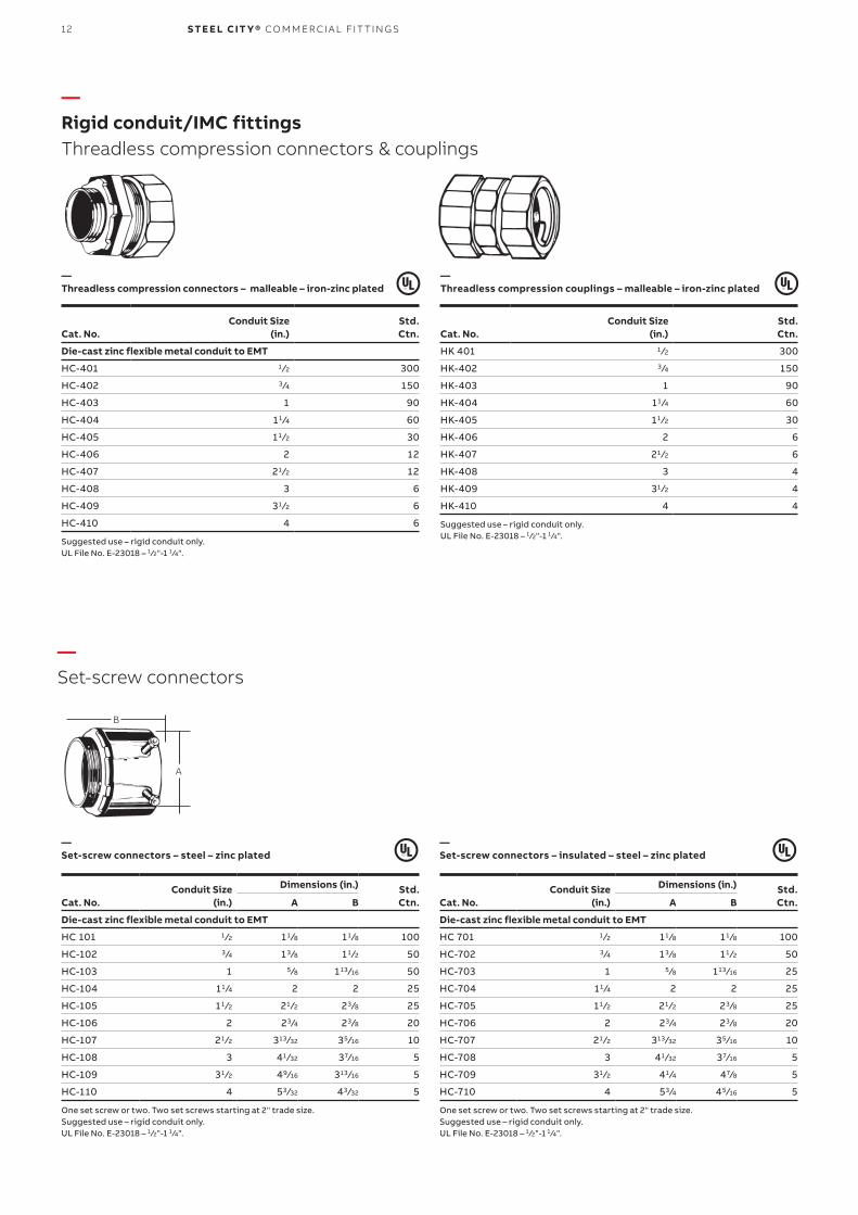
12 S TE E L CIT Y® CO M M ER CI A L FIT TI N G S
Conduit Size(in.)
Dimensions (in.) Std.Ctn.Cat. No. A B
Die-cast zinc flexible metal conduit to EMT
HC 101 1 ⁄2 11 ⁄8 11 ⁄8 100
HC-102 3 ⁄4 13 ⁄8 11 ⁄2 50
HC-103 1 5 ⁄8 113 ⁄16 50
HC-104 11 ⁄4 2 2 25
HC-105 11 ⁄2 21 ⁄2 23 ⁄8 25
HC-106 2 23 ⁄4 23 ⁄8 20
HC-107 21 ⁄2 313 ⁄32 35 ⁄16 10
HC-108 3 41 ⁄32 37⁄16 5
HC-109 31 ⁄2 49⁄16 313 ⁄16 5
HC-110 4 53 ⁄32 43 ⁄32 5
One set screw or two. Two set screws starting at 2" trade size.Suggested use – rigid conduit only.UL File No. E-23018 – 1 ⁄2"-1 1 ⁄4".
Conduit Size(in.)
Dimensions (in.) Std.Ctn.Cat. No. A B
Die-cast zinc flexible metal conduit to EMT
HC 701 1 ⁄2 11 ⁄8 11 ⁄8 100
HC-702 3 ⁄4 13 ⁄8 11 ⁄2 50
HC-703 1 5 ⁄8 113 ⁄16 25
HC-704 11 ⁄4 2 2 25
HC-705 11 ⁄2 21 ⁄2 23 ⁄8 25
HC-706 2 23 ⁄4 23 ⁄8 20
HC-707 21 ⁄2 313 ⁄32 35 ⁄16 10
HC-708 3 41 ⁄32 37⁄16 5
HC-709 31 ⁄2 41 ⁄4 47⁄8 5
HC-710 4 53 ⁄4 45 ⁄16 5
One set screw or two. Two set screws starting at 2" trade size.Suggested use – rigid conduit only.UL File No. E-23018 – 1 ⁄2"-1 1 ⁄4".
—Set-screw connectors – steel – zinc plated
—Set-screw connectors – insulated – steel – zinc plated
—Rigid conduit/IMC fittingsThreadless compression connectors & couplings
—Set-screw connectors
Conduit Size(in.)
Std.Ctn.Cat. No.
Die-cast zinc flexible metal conduit to EMT
HC-401 1 ⁄2 300
HC-402 3 ⁄4 150
HC-403 1 90
HC-404 11 ⁄4 60
HC-405 11 ⁄2 30
HC-406 2 12
HC-407 21 ⁄2 12
HC-408 3 6
HC-409 31 ⁄2 6
HC-410 4 6
Suggested use – rigid conduit only.UL File No. E-23018 – 1 ⁄2"-1 1 ⁄4".
Conduit Size(in.)
Std.Ctn.Cat. No.
HK 401 1 ⁄2 300
HK-402 3 ⁄4 150
HK-403 1 90
HK-404 11 ⁄4 60
HK-405 11 ⁄2 30
HK-406 2 6
HK-407 21 ⁄2 6
HK-408 3 4
HK-409 31 ⁄2 4
HK-410 4 4
Suggested use – rigid conduit only.UL File No. E-23018 – 1 ⁄2"-1 1 ⁄4".
—Threadless compression connectors – malleable – iron-zinc plated
A
B
—Threadless compression couplings – malleable – iron-zinc plated
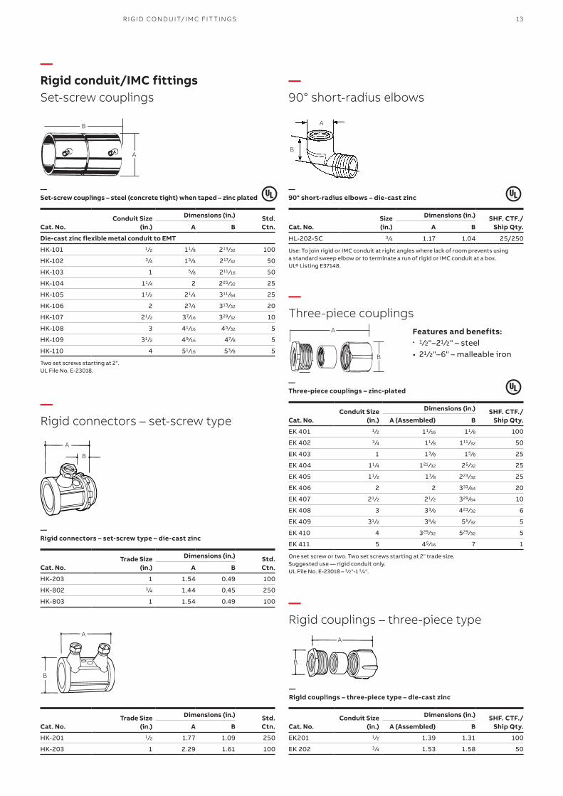
13R I G I D CO N D U IT/I M C FIT TI N G S
—Rigid conduit/IMC fittingsSet-screw couplings
—90° short-radius elbows
—Three-piece couplings
—Rigid couplings – three-piece type
—Rigid connectors – set-screw type
—Set-screw couplings – steel (concrete tight) when taped – zinc plated
—90° short-radius elbows – die-cast zinc
—Three-piece couplings – zinc-plated
—Rigid connectors – set-screw type – die-cast zinc
Features and benefits:• 1 ⁄2"–21 ⁄2" – steel• 21 ⁄2"–6" – malleable iron
Conduit Size(in.)
Dimensions (in.) Std.Ctn.Cat. No. A B
Die-cast zinc flexible metal conduit to EMT
HK-101 1 ⁄2 11 ⁄8 213 ⁄32 100
HK-102 3 ⁄4 13 ⁄8 217⁄32 50
HK-103 1 5 ⁄8 211 ⁄16 50
HK-104 11 ⁄4 2 225 ⁄32 25
HK-105 11 ⁄2 21 ⁄4 311 ⁄64 25
HK-106 2 23 ⁄4 313 ⁄32 20
HK-107 21 ⁄2 37⁄16 329 ⁄32 10
HK-108 3 41 ⁄16 45 ⁄32 5
HK-109 31 ⁄2 49⁄16 47⁄8 5
HK-110 4 51 ⁄16 53 ⁄8 5
Two set screws starting at 2".UL File No. E-23018.
Size(in.)
Dimensions (in.) SHF. CTF./Ship Qty.Cat. No. A B
HL-202-SC 3 ⁄4 1.17 1.04 25/250
Use: To join rigid or IMC conduit at right angles where lack of room prevents usinga standard sweep elbow or to terminate a run of rigid or IMC conduit at a box.UL® Listing E37148.
Conduit Size(in.)
Dimensions (in.) SHF. CTF./Ship Qty.Cat. No. A (Assembled) B
EK 401 1 ⁄2 11 ⁄16 11 ⁄8 100
EK 402 3 ⁄4 11 ⁄8 111 ⁄32 50
EK 403 1 13 ⁄8 15 ⁄8 25
EK 404 11 ⁄4 121 ⁄32 25 ⁄32 25
EK 405 11 ⁄2 17⁄8 223 ⁄32 25
EK 406 2 2 333 ⁄64 20
EK 407 21 ⁄2 21 ⁄2 329 ⁄64 10
EK 408 3 33 ⁄8 423 ⁄32 6
EK 409 31 ⁄2 35 ⁄8 55 ⁄32 5
EK 410 4 329⁄32 529 ⁄32 5
EK 411 5 45 ⁄16 7 1
One set screw or two. Two set screws starting at 2" trade size.Suggested use — rigid conduit only.UL File No. E-23018 – 1 ⁄2"-1 1 ⁄4".
Conduit Size(in.)
Dimensions (in.) SHF. CTF./Ship Qty.Cat. No. A (Assembled) B
EK201 1 ⁄2 1.39 1.31 100
EK 202 3 ⁄4 1.53 1.58 50
Trade Size(in.)
Dimensions (in.) Std.Ctn.Cat. No. A B
HK-203 1 1.54 0.49 100
HK-802 3 ⁄4 1.44 0.45 250
HK-803 1 1.54 0.49 100
Trade Size(in.)
Dimensions (in.) Std.Ctn.Cat. No. A B
HK-201 1 ⁄2 1.77 1.09 250
HK-203 1 2.29 1.61 100
A
B
A
B
A
B
A
B
A
B
—Rigid couplings – three-piece type – die-cast zinc
A
B
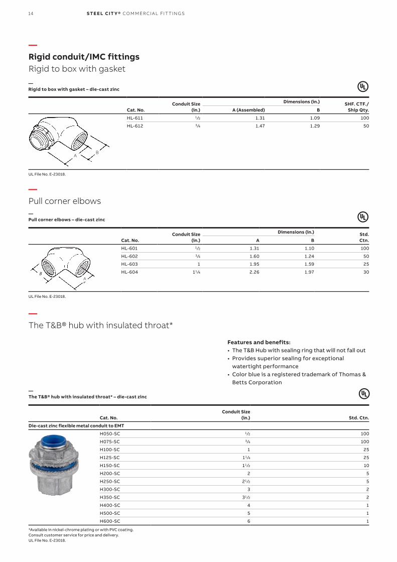
14 S TE E L CIT Y® CO M M ER CI A L FIT TI N G S
—Rigid conduit/IMC fittingsRigid to box with gasket
—The T&B® hub with insulated throat*
—Pull corner elbows
Conduit Size(in.)
Dimensions (in.) SHF. CTF./ Ship Qty.Cat. No. A (Assembled) B
HL-611 1 ⁄2 1.31 1.09 100
HL-612 3 ⁄4 1.47 1.29 50
UL File No. E-23018.
—Rigid to box with gasket – die-cast zinc
AB
Conduit Size(in.) Std. Ctn.Cat. No.
Die-cast zinc flexible metal conduit to EMT
H050-SC 1 ⁄2 100
H075-SC 3 ⁄4 100
H100-SC 1 25
H125-SC 11 ⁄4 25
H150-SC 11 ⁄2 10
H200-SC 2 5
H250-SC 21 ⁄2 5
H300-SC 3 2
H350-SC 31 ⁄2 2
H400-SC 4 1
H500-SC 5 1
H600-SC 6 1
*Available in nickel-chrome plating or with PVC coating.Consult customer service for price and delivery.UL File No. E-23018.
—The T&B® hub with insulated throat* – die-cast zinc
Features and benefits:• The T&B Hub with sealing ring that will not fall out• Provides superior sealing for exceptional
watertight performance• Color blue is a registered trademark of Thomas &
Betts Corporation
—Pull corner elbows – die-cast zinc
Conduit Size(in.)
Dimensions (in.) Std.Ctn.Cat. No. A B
HL-601 1 ⁄2 1.31 1.10 100
HL-602 3 ⁄4 1.60 1.24 50
HL-603 1 1.95 1.59 25
HL-604 11 ⁄4 2.26 1.97 30
UL File No. E-23018.
AB
15R I G I D CO N D U IT/I M C FIT TI N G S
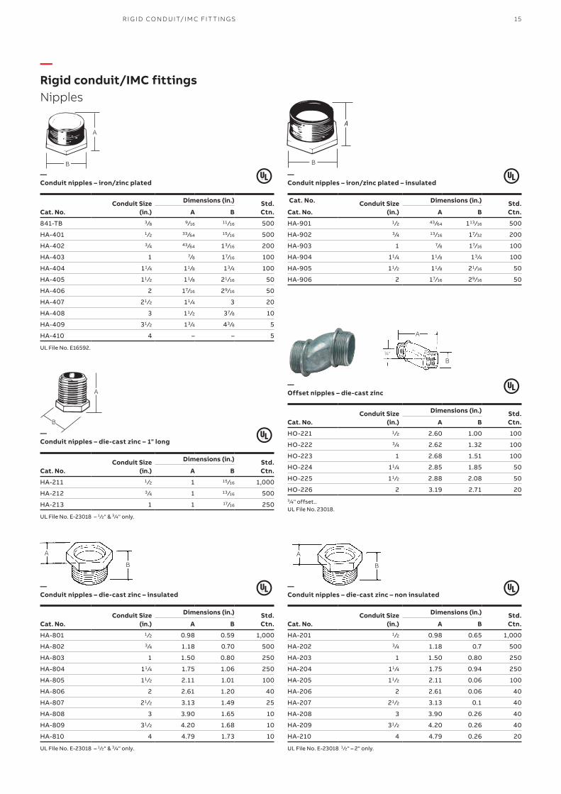
—Rigid conduit/IMC fittingsNipples
—Conduit nipples – iron/zinc plated
—Conduit nipples – iron/zinc plated – insulated
—Offset nipples – die-cast zinc
—Conduit nipples – die-cast zinc – non insulated
—Conduit nipples – die-cast zinc – insulated
—Conduit nipples – die-cast zinc – 1" long
Conduit Size(in.)
Dimensions (in.) Std.Ctn.Cat. No. A B
841-TB 3 ⁄8 9 ⁄16 11 ⁄16 500
HA-401 1 ⁄2 33 ⁄64 15 ⁄16 500
HA-402 3 ⁄4 43 ⁄64 13 ⁄16 200
HA-403 1 7⁄8 17⁄16 100
HA-404 11 ⁄4 11 ⁄8 13 ⁄4 100
HA-405 11 ⁄2 11 ⁄8 21 ⁄16 50
HA-406 2 17⁄16 29⁄16 50
HA-407 21 ⁄2 11 ⁄4 3 20
HA-408 3 11 ⁄2 37⁄8 10
HA-409 31 ⁄2 13 ⁄4 43 ⁄8 5
HA-410 4 – – 5
UL File No. E16592.
Cat. No. Conduit Size(in.)
Dimensions (in.) Std.Ctn.Cat. No. A B
HA-901 1 ⁄2 43 ⁄64 113 ⁄16 500
HA-902 3 ⁄4 13 ⁄16 17⁄32 200
HA-903 1 7⁄8 17⁄16 100
HA-904 11 ⁄4 11 ⁄8 13 ⁄4 100
HA-905 11 ⁄2 11 ⁄8 21 ⁄16 50
HA-906 2 17⁄16 29⁄16 50
Conduit Size(in.)
Dimensions (in.) Std.Ctn.Cat. No. A B
HO-221 1 ⁄2 2.60 1.00 100
HO-222 3 ⁄4 2.62 1.32 100
HO-223 1 2.68 1.51 100
HO-224 11 ⁄4 2.85 1.85 50
HO-225 11 ⁄2 2.88 2.08 50
HO-226 2 3.19 2.71 203 ⁄4" offset..UL File No. 23018.
Conduit Size(in.)
Dimensions (in.) Std.Ctn.Cat. No. A B
HA-801 1 ⁄2 0.98 0.59 1,000
HA-802 3 ⁄4 1.18 0.70 500
HA-803 1 1.50 0.80 250
HA-804 11 ⁄4 1.75 1.06 250
HA-805 11 ⁄2 2.11 1.01 100
HA-806 2 2.61 1.20 40
HA-807 21 ⁄2 3.13 1.49 25
HA-808 3 3.90 1.65 10
HA-809 31 ⁄2 4.20 1.68 10
HA-810 4 4.79 1.73 10
UL File No. E-23018 – 1 ⁄2" & 3 ⁄4" only.
Conduit Size(in.)
Dimensions (in.) Std.Ctn.Cat. No. A B
HA-201 1 ⁄2 0.98 0.65 1,000
HA-202 3 ⁄4 1.18 0.7 500
HA-203 1 1.50 0.80 250
HA-204 11 ⁄4 1.75 0.94 250
HA-205 11 ⁄2 2.11 0.06 100
HA-206 2 2.61 0.06 40
HA-207 21 ⁄2 3.13 0.1 40
HA-208 3 3.90 0.26 40
HA-209 31 ⁄2 4.20 0.26 40
HA-210 4 4.79 0.26 20
UL File No. E-23018 1 ⁄2" – 2" only.
Conduit Size(in.)
Dimensions (in.) Std.Ctn.Cat. No. A B
HA-211 1 ⁄2 1 15 ⁄16 1,000
HA-212 3 ⁄4 1 13 ⁄16 500
HA-213 1 1 17⁄16 250
UL File No. E-23018 – 1 ⁄2" & 3 ⁄4" only.
B
A
B
A
A
B
B
A
A
B3⁄4"
A
B
16 S TE E L CIT Y® CO M M ER CI A L FIT TI N G S
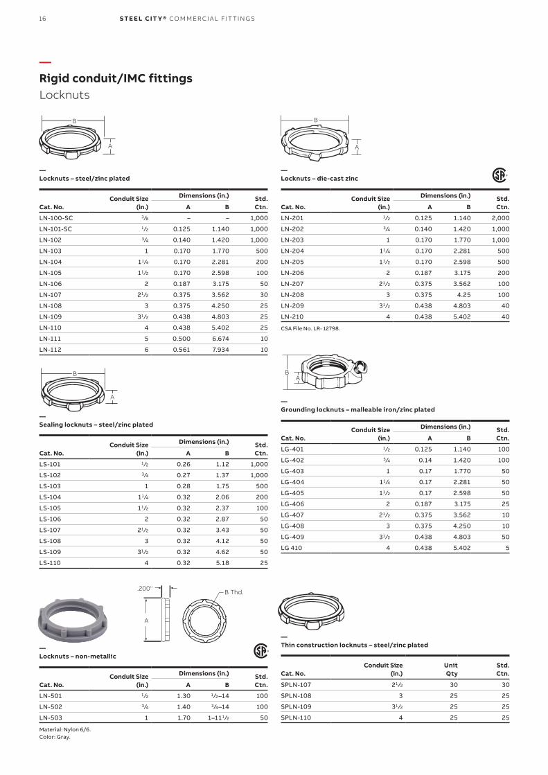
—Rigid conduit/IMC fittingsLocknuts
—Locknuts – steel/zinc plated
—Locknuts – die-cast zinc
—Grounding locknuts – malleable iron/zinc plated
—Thin construction locknuts – steel/zinc plated—
Locknuts – non-metallic
Conduit Size(in.)
Dimensions (in.) Std.Ctn.Cat. No. A B
LN-100-SC 3 ⁄8 – – 1,000
LN-101-SC 1 ⁄2 0.125 1.140 1,000
LN-102 3 ⁄4 0.140 1.420 1,000
LN-103 1 0.170 1.770 500
LN-104 11 ⁄4 0.170 2.281 200
LN-105 11 ⁄2 0.170 2.598 100
LN-106 2 0.187 3.175 50
LN-107 21 ⁄2 0.375 3.562 30
LN-108 3 0.375 4.250 25
LN-109 31 ⁄2 0.438 4.803 25
LN-110 4 0.438 5.402 25
LN-111 5 0.500 6.674 10
LN-112 6 0.561 7.934 10
Conduit Size(in.)
Dimensions (in.) Std.Ctn.Cat. No. A B
LN-201 1 ⁄2 0.125 1.140 2,000
LN-202 3 ⁄4 0.140 1.420 1,000
LN-203 1 0.170 1.770 1,000
LN-204 11 ⁄4 0.170 2.281 500
LN-205 11 ⁄2 0.170 2.598 500
LN-206 2 0.187 3.175 200
LN-207 21 ⁄2 0.375 3.562 100
LN-208 3 0.375 4.25 100
LN-209 31 ⁄2 0.438 4.803 40
LN-210 4 0.438 5.402 40
CSA File No. LR- 12798.
Conduit Size(in.)
Dimensions (in.) Std.Ctn.Cat. No. A B
LG-401 1 ⁄2 0.125 1.140 100
LG-402 3 ⁄4 0.14 1.420 100
LG-403 1 0.17 1.770 50
LG-404 11 ⁄4 0.17 2.281 50
LG-405 11 ⁄2 0.17 2.598 50
LG-406 2 0.187 3.175 25
LG-407 21 ⁄2 0.375 3.562 10
LG-408 3 0.375 4.250 10
LG-409 31 ⁄2 0.438 4.803 50
LG 410 4 0.438 5.402 5
Conduit Size(in.)
Dimensions (in.) Std.Ctn.Cat. No. A B
LS-101 1 ⁄2 0.26 1.12 1,000
LS-102 3 ⁄4 0.27 1.37 1,000
LS-103 1 0.28 1.75 500
LS-104 11 ⁄4 0.32 2.06 200
LS-105 11 ⁄2 0.32 2.37 100
LS-106 2 0.32 2.87 50
LS-107 21 ⁄2 0.32 3.43 50
LS-108 3 0.32 4.12 50
LS-109 31 ⁄2 0.32 4.62 50
LS-110 4 0.32 5.18 25
Conduit Size(in.)
UnitQty
Std.Ctn.Cat. No.
SPLN-107 21 ⁄2 30 30
SPLN-108 3 25 25
SPLN-109 31 ⁄2 25 25
SPLN-110 4 25 25
Conduit Size(in.)
Dimensions (in.) Std.Ctn.Cat. No. A B
LN-501 1 ⁄2 1.30 1 ⁄2–14 100
LN-502 3 ⁄4 1.40 3 ⁄4–14 100
LN-503 1 1.70 1–111 ⁄2 50
Material: Nylon 6/6.Color: Gray.
A
B
A
B
.200" B Thd.
A
—Sealing locknuts – steel/zinc plated
AB
A
B
17R I G I D CO N D U IT/I M C FIT TI N G S
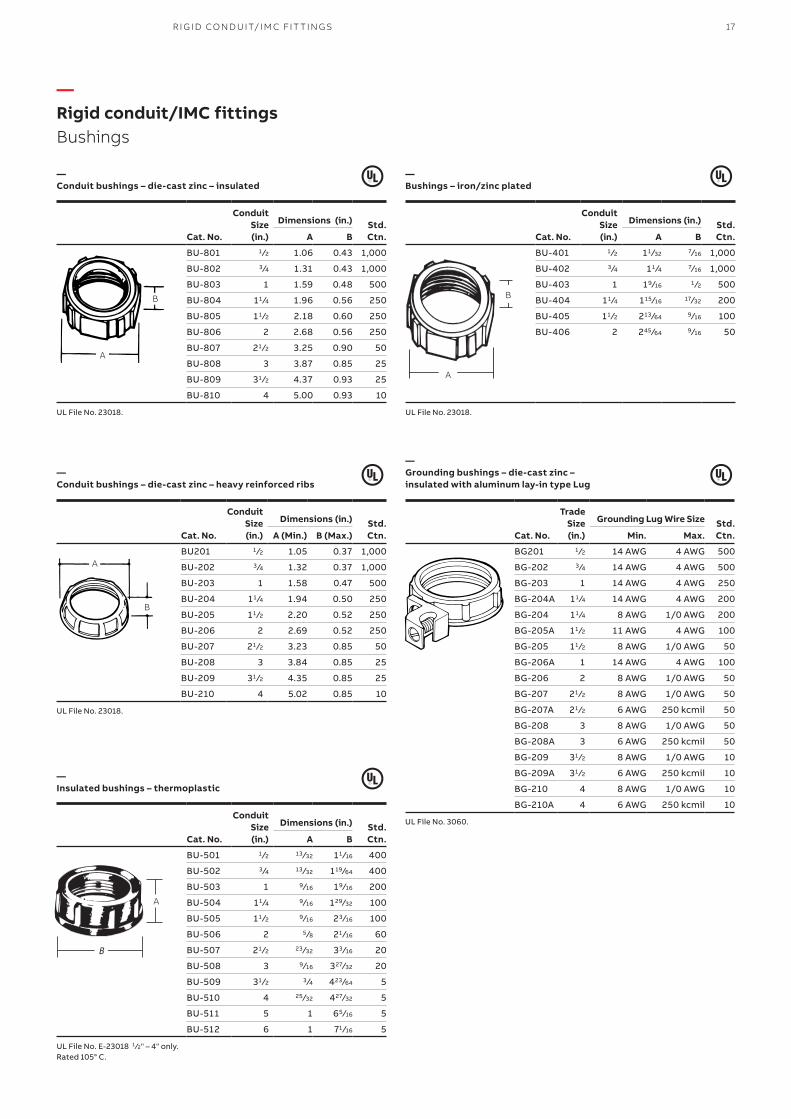
—Rigid conduit/IMC fittingsBushings
—Conduit bushings – die-cast zinc – insulated
—Bushings – iron/zinc plated
—Conduit bushings – die-cast zinc – heavy reinforced ribs
—Grounding bushings – die-cast zinc – insulated with aluminum lay-in type Lug
—Insulated bushings – thermoplastic
Conduit Size(in.)
Dimensions (in.) Std.Ctn.Cat. No. A B
BU-801 1 ⁄2 1.06 0.43 1,000
BU-802 3 ⁄4 1.31 0.43 1,000
BU-803 1 1.59 0.48 500
BU-804 11 ⁄4 1.96 0.56 250
BU-805 11 ⁄2 2.18 0.60 250
BU-806 2 2.68 0.56 250
BU-807 21 ⁄2 3.25 0.90 50
BU-808 3 3.87 0.85 25
BU-809 31 ⁄2 4.37 0.93 25
BU-810 4 5.00 0.93 10
UL File No. 23018.
Conduit Size(in.)
Dimensions (in.) Std.Ctn.Cat. No. A B
BU-401 1 ⁄2 11 ⁄32 7⁄16 1,000
BU-402 3 ⁄4 11 ⁄4 7⁄16 1,000
BU-403 1 19⁄16 1 ⁄2 500
BU-404 11 ⁄4 115 ⁄16 17⁄32 200
BU-405 11 ⁄2 213 ⁄64 9 ⁄16 100
BU-406 2 245 ⁄64 9 ⁄16 50
UL File No. 23018.
Conduit Size(in.)
Dimensions (in.) Std.Ctn.Cat. No. A (Min.) B (Max.)
BU201 1 ⁄2 1.05 0.37 1,000
BU-202 3 ⁄4 1.32 0.37 1,000
BU-203 1 1.58 0.47 500
BU-204 11 ⁄4 1.94 0.50 250
BU-205 11 ⁄2 2.20 0.52 250
BU-206 2 2.69 0.52 250
BU-207 21 ⁄2 3.23 0.85 50
BU-208 3 3.84 0.85 25
BU-209 31 ⁄2 4.35 0.85 25
BU-210 4 5.02 0.85 10
UL File No. 23018.
Trade Size(in.)
Grounding Lug Wire Size Std.Ctn.Cat. No. Min. Max.
BG201 1 ⁄2 14 AWG 4 AWG 500
BG-202 3 ⁄4 14 AWG 4 AWG 500
BG-203 1 14 AWG 4 AWG 250
BG-204A 11 ⁄4 14 AWG 4 AWG 200
BG-204 11 ⁄4 8 AWG 1/0 AWG 200
BG-205A 11 ⁄2 11 AWG 4 AWG 100
BG-205 11 ⁄2 8 AWG 1/0 AWG 50
BG-206A 1 14 AWG 4 AWG 100
BG-206 2 8 AWG 1/0 AWG 50
BG-207 21 ⁄2 8 AWG 1/0 AWG 50
BG-207A 21 ⁄2 6 AWG 250 kcmil 50
BG-208 3 8 AWG 1/0 AWG 50
BG-208A 3 6 AWG 250 kcmil 50
BG-209 31 ⁄2 8 AWG 1/0 AWG 10
BG-209A 31 ⁄2 6 AWG 250 kcmil 10
BG-210 4 8 AWG 1/0 AWG 10
BG-210A 4 6 AWG 250 kcmil 10
UL File No. 3060.Conduit
Size(in.)
Dimensions (in.) Std.Ctn.Cat. No. A B
BU-501 1 ⁄2 13 ⁄32 11 ⁄16 400
BU-502 3 ⁄4 13 ⁄32 119 ⁄64 400
BU-503 1 9⁄16 19⁄16 200
BU-504 11 ⁄4 9 ⁄16 129 ⁄32 100
BU-505 11 ⁄2 9 ⁄16 23 ⁄16 100
BU-506 2 5 ⁄8 21 ⁄16 60
BU-507 21 ⁄2 23 ⁄32 33 ⁄16 20
BU-508 3 9⁄16 327⁄32 20
BU-509 31 ⁄2 3 ⁄4 423 ⁄64 5
BU-510 4 25 ⁄32 427⁄32 5
BU-511 5 1 65 ⁄16 5
BU-512 6 1 71 ⁄16 5
UL File No. E-23018 1 ⁄2" – 4" only.Rated 105° C.
A
B
A
B
A
B
A
B
18 S TE E L CIT Y® CO M M ER CI A L FIT TI N G S
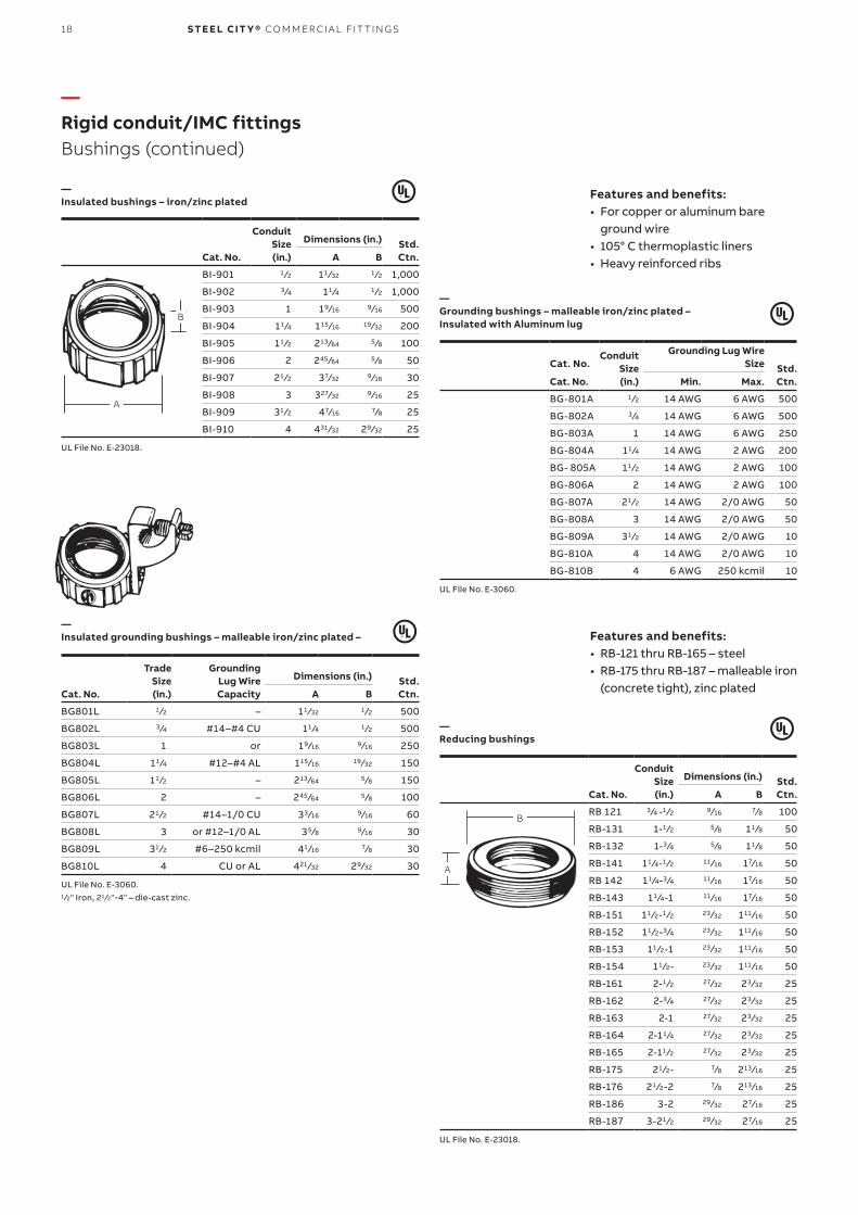
—Rigid conduit/IMC fittingsBushings (continued)
—Insulated bushings – iron/zinc plated
—Grounding bushings – malleable iron/zinc plated –Insulated with Aluminum lug
—Reducing bushings
—Insulated grounding bushings – malleable iron/zinc plated –
Conduit Size(in.)
Dimensions (in.) Std.Ctn.Cat. No. A B
BI-901 1 ⁄2 11 ⁄32 1 ⁄2 1,000
BI-902 3 ⁄4 11 ⁄4 1 ⁄2 1,000
BI-903 1 19⁄16 9 ⁄16 500
BI-904 11 ⁄4 115 ⁄16 19 ⁄32 200
BI-905 11 ⁄2 213 ⁄64 5 ⁄8 100
BI-906 2 245 ⁄64 5 ⁄8 50
BI-907 21 ⁄2 37⁄32 9 ⁄16 30
BI-908 3 327⁄32 9 ⁄16 25
BI-909 31 ⁄2 47⁄16 7⁄8 25
BI-910 4 431 ⁄32 29⁄32 25
UL File No. E-23018.
Cat. No.
Conduit Size(in.)
Grounding Lug Wire Size Std.
Ctn.Cat. No. Min. Max.
BG-801A 1 ⁄2 14 AWG 6 AWG 500
BG-802A 3 ⁄4 14 AWG 6 AWG 500
BG-803A 1 14 AWG 6 AWG 250
BG-804A 11 ⁄4 14 AWG 2 AWG 200
BG- 805A 11 ⁄2 14 AWG 2 AWG 100
BG-806A 2 14 AWG 2 AWG 100
BG-807A 21 ⁄2 14 AWG 2/0 AWG 50
BG-808A 3 14 AWG 2/0 AWG 50
BG-809A 31 ⁄2 14 AWG 2/0 AWG 10
BG-810A 4 14 AWG 2/0 AWG 10
BG-810B 4 6 AWG 250 kcmil 10
UL File No. E-3060.
Conduit Size(in.)
Dimensions (in.) Std.Ctn.Cat. No. A B
RB 121 3 ⁄4 -1 ⁄2 9 ⁄16 7⁄8 100
RB-131 1-1 ⁄2 5 ⁄8 11 ⁄8 50
RB-132 1-3 ⁄4 5 ⁄8 11 ⁄8 50
RB-141 11 ⁄4-1 ⁄2 11 ⁄16 17⁄16 50
RB 142 11 ⁄4-3 ⁄4 11 ⁄16 17⁄16 50
RB-143 11 ⁄4-1 11 ⁄16 17⁄16 50
RB-151 11 ⁄2-1 ⁄2 23 ⁄32 111 ⁄16 50
RB-152 11 ⁄2-3 ⁄4 23 ⁄32 111 ⁄16 50
RB-153 11 ⁄2-1 23 ⁄32 111 ⁄16 50
RB-154 11 ⁄2- 23 ⁄32 111 ⁄16 50
RB-161 2-1 ⁄2 27⁄32 23 ⁄32 25
RB-162 2-3 ⁄4 27⁄32 23 ⁄32 25
RB-163 2-1 27⁄32 23 ⁄32 25
RB-164 2-11 ⁄4 27⁄32 23 ⁄32 25
RB-165 2-11 ⁄2 27⁄32 23 ⁄32 25
RB-175 21 ⁄2- 7⁄8 213 ⁄16 25
RB-176 21 ⁄2-2 7⁄8 213 ⁄16 25
RB-186 3-2 29 ⁄32 27⁄16 25
RB-187 3-21 ⁄2 29 ⁄32 27⁄16 25
UL File No. E-23018.
Trade Size(in.)
GroundingLug WireCapacity
Dimensions (in.) Std.Ctn.Cat. No. A B
BG801L 1 ⁄2 – 11 ⁄32 1 ⁄2 500
BG802L 3 ⁄4 #14–#4 CU 11 ⁄4 1 ⁄2 500
BG803L 1 or 19⁄16 9 ⁄16 250
BG804L 11 ⁄4 #12–#4 AL 115 ⁄16 19 ⁄32 150
BG805L 11 ⁄2 – 213 ⁄64 5 ⁄8 150
BG806L 2 – 245 ⁄64 5 ⁄8 100
BG807L 21 ⁄2 #14–1/0 CU 33 ⁄16 9 ⁄16 60
BG808L 3 or #12–1/0 AL 35 ⁄8 9 ⁄16 30
BG809L 31 ⁄2 #6–250 kcmil 41 ⁄16 7⁄8 30
BG810L 4 CU or AL 421 ⁄32 29⁄32 30
UL File No. E-3060.1 ⁄2" Iron, 21 ⁄2"-4" – die-cast zinc.
Features and benefits:• For copper or aluminum bare
ground wire• 105° C thermoplastic liners• Heavy reinforced ribs
Features and benefits:• RB-121 thru RB-165 – steel• RB-175 thru RB-187 – malleable iron
(concrete tight), zinc plated
A
B
B
A
19R I G I D CO N D U IT/I M C FIT TI N G S
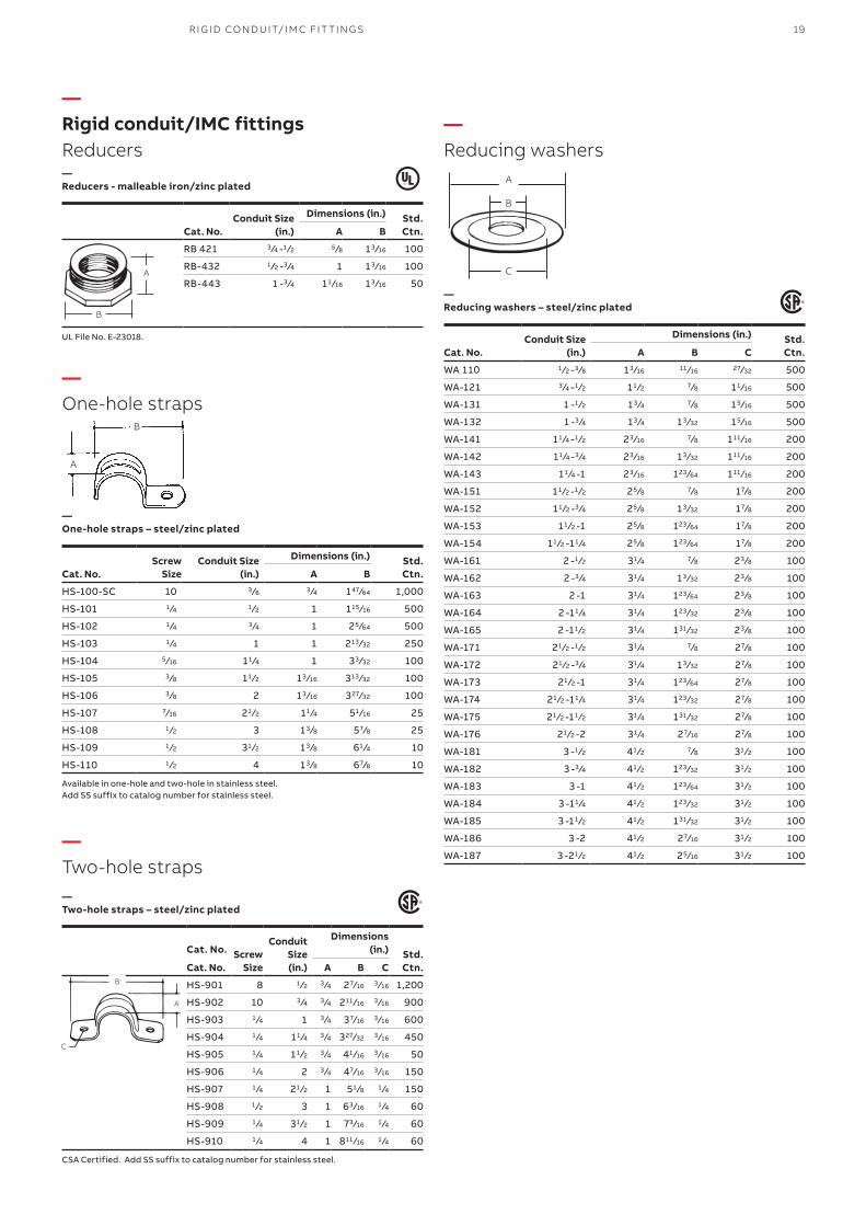
—Rigid conduit/IMC fittingsReducers
—Reducing washers
—Reducers - malleable iron/zinc plated
—Reducing washers – steel/zinc plated
Conduit Size(in.)
Dimensions (in.) Std.Ctn.Cat. No. A B
RB 421 3 ⁄4 -1 ⁄2 5 ⁄8 13 ⁄16 100
RB-432 1 ⁄2 -3 ⁄4 1 13 ⁄16 100
RB-443 1 -3 ⁄4 11 ⁄16 13 ⁄16 50
UL File No. E-23018. Conduit Size(in.)
Dimensions (in.) Std.Ctn.Cat. No. A B C
WA 110 1 ⁄2 -3 ⁄8 13 ⁄16 11 ⁄16 27⁄32 500
WA-121 3 ⁄4 -1 ⁄2 11 ⁄2 7⁄8 11 ⁄16 500
WA-131 1 -1 ⁄2 13 ⁄4 7⁄8 15 ⁄16 500
WA-132 1 -3 ⁄4 13 ⁄4 13 ⁄32 15 ⁄16 500
WA-141 11 ⁄4 -1 ⁄2 23 ⁄16 7⁄8 111 ⁄16 200
WA-142 11 ⁄4 -3 ⁄4 23 ⁄16 13 ⁄32 111 ⁄16 200
WA-143 11 ⁄4 -1 23 ⁄16 123 ⁄64 111 ⁄16 200
WA-151 11 ⁄2 -1 ⁄2 25 ⁄8 7⁄8 17⁄8 200
WA-152 11 ⁄2 -3 ⁄4 25 ⁄8 13 ⁄32 17⁄8 200
WA-153 11 ⁄2 -1 25 ⁄8 123 ⁄64 17⁄8 200
WA-154 11 ⁄2 -11 ⁄4 25 ⁄8 123 ⁄64 17⁄8 200
WA-161 2 -1 ⁄2 31 ⁄4 7⁄8 23 ⁄8 100
WA-162 2 -3 ⁄4 31 ⁄4 13 ⁄32 23 ⁄8 100
WA-163 2 -1 31 ⁄4 123 ⁄64 23 ⁄8 100
WA-164 2 -11 ⁄4 31 ⁄4 123 ⁄32 23 ⁄8 100
WA-165 2 -11 ⁄2 31 ⁄4 131 ⁄32 23 ⁄8 100
WA-171 21 ⁄2 -1 ⁄2 31 ⁄4 7⁄8 27⁄8 100
WA-172 21 ⁄2 -3 ⁄4 31 ⁄4 13 ⁄32 27⁄8 100
WA-173 21 ⁄2 -1 31 ⁄4 123 ⁄64 27⁄8 100
WA-174 21 ⁄2 -11 ⁄4 31 ⁄4 123 ⁄32 27⁄8 100
WA-175 21 ⁄2 -11 ⁄2 31 ⁄4 131 ⁄32 27⁄8 100
WA-176 21 ⁄2 -2 31 ⁄4 27⁄16 27⁄8 100
WA-181 3 -1 ⁄2 41 ⁄2 7⁄8 31 ⁄2 100
WA-182 3 -3 ⁄4 41 ⁄2 123 ⁄32 31 ⁄2 100
WA-183 3 -1 41 ⁄2 123 ⁄64 31 ⁄2 100
WA-184 3 -11 ⁄4 41 ⁄2 123 ⁄32 31 ⁄2 100
WA-185 3 -11 ⁄2 41 ⁄2 131 ⁄32 31 ⁄2 100
WA-186 3 -2 41 ⁄2 27⁄16 31 ⁄2 100
WA-187 3 -21 ⁄2 41 ⁄2 25 ⁄16 31 ⁄2 100
B
A
A
B
C
—One-hole straps
—Two-hole straps
—One-hole straps – steel/zinc plated
—Two-hole straps – steel/zinc plated
Screw Size
Conduit Size(in.)
Dimensions (in.) Std.Ctn.Cat. No. A B
HS-100-SC 10 3 ⁄8 3 ⁄4 147⁄64 1,000
HS-101 1 ⁄4 1 ⁄2 1 115 ⁄16 500
HS-102 1 ⁄4 3 ⁄4 1 25 ⁄64 500
HS-103 1 ⁄4 1 1 213 ⁄32 250
HS-104 5 ⁄16 11 ⁄4 1 33 ⁄32 100
HS-105 3 ⁄8 11 ⁄2 13 ⁄16 313 ⁄32 100
HS-106 3 ⁄8 2 13 ⁄16 327⁄32 100
HS-107 7⁄16 21 ⁄2 11 ⁄4 51 ⁄16 25
HS-108 1 ⁄2 3 13 ⁄8 57⁄8 25
HS-109 1 ⁄2 31 ⁄2 13 ⁄8 61 ⁄4 10
HS-110 1 ⁄2 4 13 ⁄8 67⁄8 10
Available in one-hole and two-hole in stainless steel.Add SS suffix to catalog number for stainless steel.
Cat. No. Screw
Size
Conduit Size(in.)
Dimensions (in.) Std.
Ctn.Cat. No. A B C
HS-901 8 1 ⁄2 3 ⁄4 27⁄16 3 ⁄16 1,200
HS-902 10 3 ⁄4 3 ⁄4 211 ⁄16 3 ⁄16 900
HS-903 1 ⁄4 1 3 ⁄4 37⁄16 3 ⁄16 600
HS-904 1 ⁄4 11 ⁄4 3 ⁄4 327⁄32 3 ⁄16 450
HS-905 1 ⁄4 11 ⁄2 3 ⁄4 41 ⁄16 3 ⁄16 50
HS-906 1 ⁄4 2 3 ⁄4 47⁄16 3 ⁄16 150
HS-907 1 ⁄4 21 ⁄2 1 51 ⁄8 1 ⁄4 150
HS-908 1 ⁄2 3 1 63 ⁄16 1 ⁄4 60
HS-909 1 ⁄4 31 ⁄2 1 73 ⁄16 1 ⁄4 60
HS-910 1 ⁄4 4 1 811 ⁄16 1 ⁄4 60
CSA Certified. Add SS suffix to catalog number for stainless steel.
A
B
A
B
C
20 S TE E L CIT Y® CO M M ER CI A L FIT TI N G S
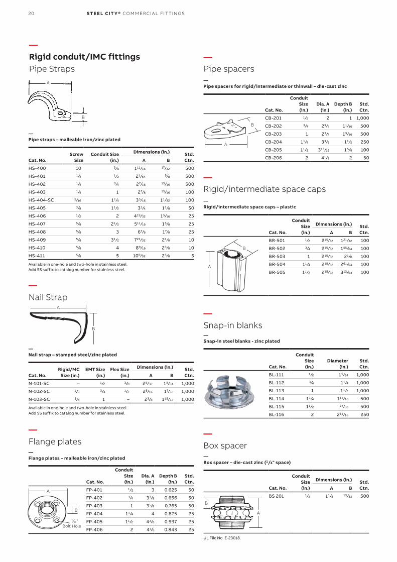
—Rigid conduit/IMC fittingsPipe Straps
—Nail Strap
—Flange plates
—Pipe spacers
—Rigid/intermediate space caps
—Box spacer
—Snap-in blanks
—Flange plates – malleable iron/zinc plated
—Pipe spacers for rigid/intermediate or thinwall – die-cast zinc
Conduit Size(in.)
Dia. A(in.)
Depth B(in.)
Std.Ctn.Cat. No.
FP-401 1 ⁄2 3 0.625 50
FP-402 3 ⁄4 33 ⁄8 0.656 50
FP-403 1 35 ⁄8 0.765 50
FP-404 11 ⁄4 4 0.875 25
FP-405 11 ⁄2 43 ⁄8 0.937 25
FP-406 2 47⁄8 0.843 25
Conduit Size(in.)
Dia. A(in.)
Depth B(in.)
Std.Ctn.Cat. No.
CB-201 1 ⁄2 2 1 1,000
CB-202 3 ⁄4 23 ⁄8 11 ⁄16 500
CB-203 1 23 ⁄4 15 ⁄16 500
CB-204 11 ⁄4 33 ⁄8 11 ⁄2 250
CB-205 11 ⁄2 313 ⁄16 15 ⁄8 100
CB-206 2 41 ⁄2 2 50Screw
SizeConduit Size
(in.)
Dimensions (in.) Std.Ctn.Cat. No. A B
HS-400 10 3 ⁄8 111 ⁄16 17⁄32 500
HS-401 1 ⁄4 1 ⁄2 21 ⁄64 5 ⁄8 500
HS-402 1 ⁄4 3 ⁄4 27⁄16 13 ⁄16 500
HS-403 1 ⁄4 1 27⁄8 15 ⁄16 100
HS-404-SC 5 ⁄16 11 ⁄4 35 ⁄16 11 ⁄32 100
HS-405 3 ⁄8 11 ⁄2 33 ⁄4 11 ⁄8 50
HS-406 1 ⁄2 2 419 ⁄32 15 ⁄16 25
HS-407 5 ⁄8 21 ⁄2 511 ⁄16 15 ⁄8 25
HS-408 5 ⁄8 3 67⁄8 17⁄8 25
HS-409 5 ⁄8 31 ⁄2 723 ⁄32 21 ⁄8 10
HS-410 5 ⁄8 4 89⁄16 23 ⁄8 10
HS-411 5 ⁄8 5 109⁄32 25 ⁄8 5
Available in one-hole and two-hole in stainless steel.Add SS suffix to catalog number for stainless steel.
Rigid/MC Size (in.)
EMT Size(in.)
Flex Size(in.)
Dimensions (in.) Std.Ctn.Cat. No. A B
N-101-SC – 1 ⁄2 3 ⁄8 25 ⁄32 15 ⁄64 1,000
N-102-SC 1 ⁄2 3 ⁄4 1 ⁄2 25 ⁄16 17⁄32 1,000
N-103-SC 3 ⁄4 1 – 23 ⁄8 115 ⁄32 1,000
Available in one-hole and two-hole in stainless steel.Add SS suffix to catalog number for stainless steel.
A
B
—Pipe straps – malleable iron/zinc plated
—Nail strap – stamped steel/zinc plated
B
A
5⁄16"Bolt Hole
B
A
A
B
—Rigid/intermediate space caps – plastic
—Box spacer – die-cast zinc (1/4" space)
—Snap-in steel blanks - zinc plated
Conduit Size(in.)
Dimensions (in.) Std.Ctn.Cat. No. A B
BR-501 1 ⁄2 215 ⁄32 121 ⁄32 100
BR-502 3 ⁄4 215 ⁄32 155 ⁄64 100
BR-503 1 215 ⁄32 21 ⁄8 100
BR-504 11 ⁄4 215 ⁄32 261 ⁄64 100
BR-505 11 ⁄2 215 ⁄32 313 ⁄64 100
Conduit Size(in.)
Dimensions (in.) Std.Ctn.Cat. No. A B
BS 201 1 ⁄2 11 ⁄8 13 ⁄32 500
UL File No. E-23018.
Conduit Size(in.)
Diameter (in.)
Std.Ctn.Cat. No.
BL-111 1 ⁄2 15 ⁄64 1,000
BL-112 3 ⁄4 11 ⁄4 1,000
BL-113 1 11 ⁄2 1,000
BL-114 11 ⁄4 113 ⁄16 500
BL-115 11 ⁄2 27⁄32 500
BL-116 2 211 ⁄16 250
A
B
A
B
21
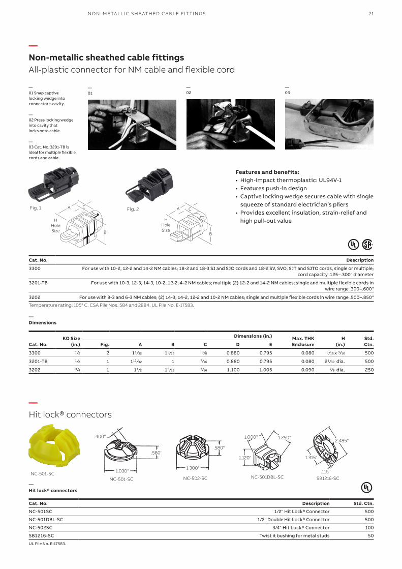
—Non-metallic sheathed cable fittingsAll-plastic connector for NM cable and flexible cord
—01 Snap captive locking wedge intoconnector’s cavity.
— 02 Press locking wedge into cavity thatlocks onto cable.
— 03 Cat. No. 3201-TB is ideal for multiple flexiblecords and cable.
Cat. No. Description Std. Ctn.
NC-501SC 1⁄2" Hit Lock® Connector 500
NC-501DBL-SC 1⁄2" Double Hit Lock® Connector 500
NC-502SC 3⁄4" Hit Lock® Connector 100
SB1216-SC Twist it bushing for metal studs 50
KO Size(in.)
Dimensions (in.) Max. THK Enclosure
H(in.)
Std.Ctn.Cat. No. Fig. A B C D E
3300 1 ⁄2 2 11 ⁄32 15 ⁄16 3 ⁄8 0.880 0.795 0.080 5 ⁄16 x 9 ⁄16 500
3201-TB 1 ⁄2 1 111 ⁄32 1 7⁄16 0.880 0.795 0.080 21 ⁄32 dia. 500
3202 3 ⁄4 1 11 ⁄2 15 ⁄16 7⁄16 1.100 1.005 0.090 7⁄8 dia. 250
—Dimensions
—01
—02
—03
—Hit lock® connectors
—Hit lock® connectors
Features and benefits:• High-impact thermoplastic: UL94V-1• Features push-in design• Captive locking wedge secures cable with single
squeeze of standard electrician’s pliers• Provides excellent insulation, strain-relief and
high pull-out value
Fig. 1 Fig. 2
H Hole Size
A
B
C A
B
C
H Hole Size
NC-501-SC
1.250"1.000"
1.120"
NC-501DBL-SC
1.000" 1.250"
1.120"
1.300"
.580"
NC-502-SC
.580"
1.300"
.400"
.580"
1.030"
NC-501-SC
.400"
.580"
1.030"
2.485"
1.315"
.115"
SB1216-SC
2.485"
1.315"
.115"
Cat. No. Description
3300 For use with 10-2, 12-2 and 14-2 NM cables; 18-2 and 18-3 SJ and SJO cords and 18-2 SV, SVO, SJT and SJTO cords, single or multiple; cord capacity .125–.300" diameter
3201-TB For use with 10-3, 12-3, 14-3, 10-2, 12-2, 4-2 NM cables; multiple (2) 12-2 and 14-2 NM cables; single and multiple flexible cords in wire range .300–.600"
3202 For use with 8-3 and 6-3 NM cables; (2) 14-3, 14-2, 12-2 and 10-2 NM cables; single and multiple flexible cords in wire range .500–.850"
Temperature rating: 105° C. CSA File Nos. 584 and 2884. UL File No. E-17583.
UL File No. E-17583.
N O N - M E TA L L I C SH E ATH ED C A B L E FIT TI N G S
22 S TE E L CIT Y® CO M M ER CI A L FIT TI N G S
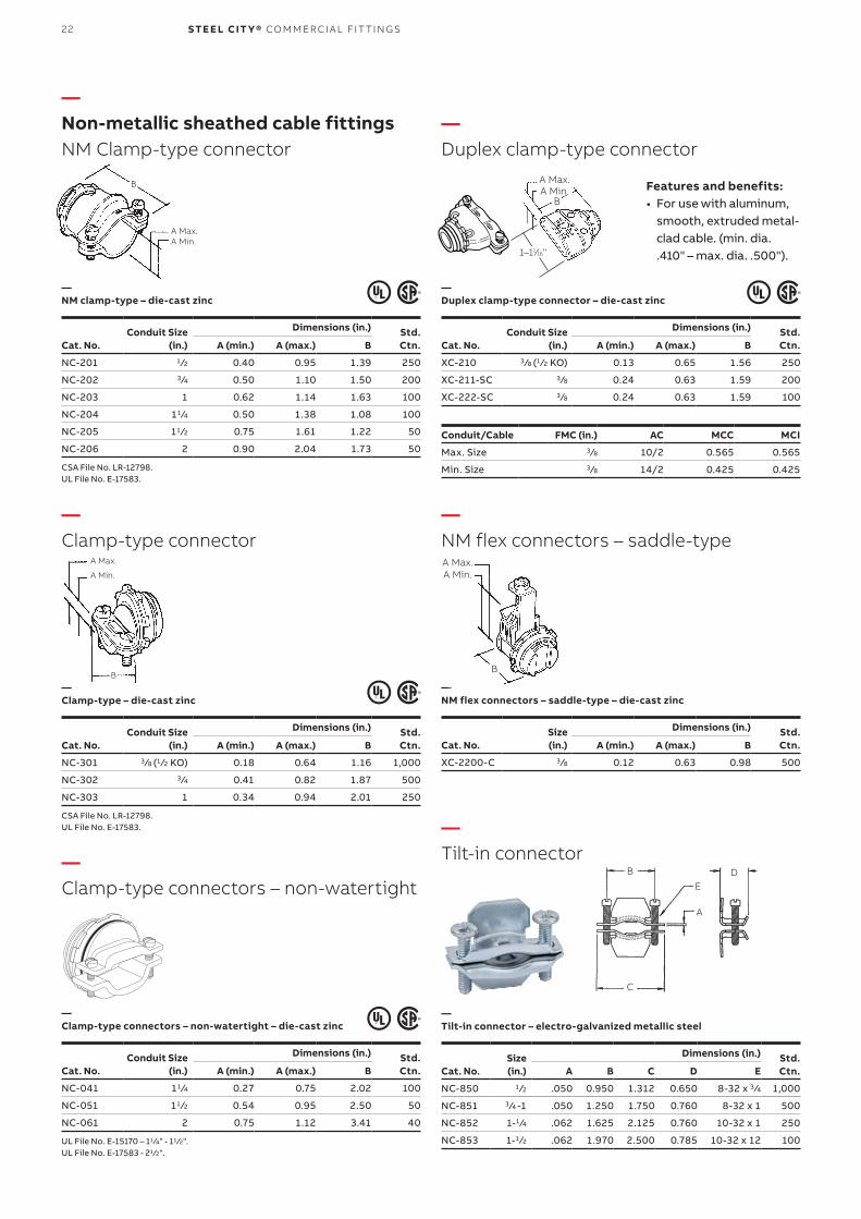
—Non-metallic sheathed cable fittingsNM Clamp-type connector
—Duplex clamp-type connector
—NM flex connectors – saddle-type
—Tilt-in connector
—Clamp-type connector
—Clamp-type connectors – non-watertight
Conduit Size(in.)
Dimensions (in.) Std.Ctn.Cat. No. A (min.) A (max.) B
NC-201 1 ⁄2 0.40 0.95 1.39 250
NC-202 3 ⁄4 0.50 1.10 1.50 200
NC-203 1 0.62 1.14 1.63 100
NC-204 11 ⁄4 0.50 1.38 1.08 100
NC-205 11 ⁄2 0.75 1.61 1.22 50
NC-206 2 0.90 2.04 1.73 50
CSA File No. LR-12798.UL File No. E-17583.
Conduit Size(in.)
Dimensions (in.) Std.Ctn.Cat. No. A (min.) A (max.) B
XC-210 3 ⁄8 (1 ⁄2 KO) 0.13 0.65 1.56 250
XC-211-SC 3 ⁄8 0.24 0.63 1.59 200
XC-222-SC 3 ⁄8 0.24 0.63 1.59 100
Size(in.)
Dimensions (in.) Std.Ctn.Cat. No. A (min.) A (max.) B
XC-2200-C 3 ⁄8 0.12 0.63 0.98 500
Size(in.)
Dimensions (in.) Std.Ctn.Cat. No. A B C D E
NC-850 1 ⁄2 .050 0.950 1.312 0.650 8-32 x 3 ⁄4 1,000
NC-851 3 ⁄4 -1 .050 1.250 1.750 0.760 8-32 x 1 500
NC-852 1-1 ⁄4 .062 1.625 2.125 0.760 10-32 x 1 250
NC-853 1-1 ⁄2 .062 1.970 2.500 0.785 10-32 x 12 100
Conduit/Cable FMC (in.) AC MCC MCI
Max. Size 3 ⁄8 10/2 0.565 0.565
Min. Size 3 ⁄8 14/2 0.425 0.425
Conduit Size(in.)
Dimensions (in.) Std.Ctn.Cat. No. A (min.) A (max.) B
NC-301 3 ⁄8 (1 ⁄2 KO) 0.18 0.64 1.16 1,000
NC-302 3 ⁄4 0.41 0.82 1.87 500
NC-303 1 0.34 0.94 2.01 250
CSA File No. LR-12798.UL File No. E-17583.
Conduit Size(in.)
Dimensions (in.) Std.Ctn.Cat. No. A (min.) A (max.) B
NC-041 11 ⁄4 0.27 0.75 2.02 100
NC-051 11 ⁄2 0.54 0.95 2.50 50
NC-061 2 0.75 1.12 3.41 40
UL File No. E-15170 – 11 ⁄4" - 11 ⁄2".UL File No. E-17583 - 21 ⁄2".
—NM clamp-type – die-cast zinc
—Duplex clamp-type connector – die-cast zinc
—NM flex connectors – saddle-type – die-cast zinc
—Tilt-in connector – electro-galvanized metallic steel
—Clamp-type – die-cast zinc
—Clamp-type connectors – non-watertight – die-cast zinc
B
A Max.A Min.
B
A Max.
A Min.
1–11⁄16"
B
A Max. A Min. Features and benefits:
• For use with aluminum, smooth, extruded metal-clad cable. (min. dia. .410" – max. dia. .500").
A Max. A Min.
B
A
B D
C
E
23
—Duplex clamp-type connector
—NM flex connectors – saddle-type
—Tilt-in connector
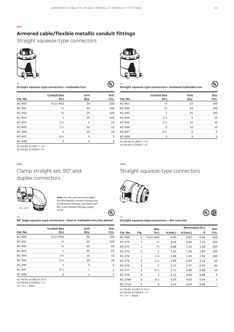
—Armored cable/flexible metallic conduit fittingsStraight squeeze-type connectors
—Clamp straight set, 90° and duplex connectors
—Straight squeeze-type connectors
—Straight squeeze-type connectors – malleable iron
—Straight squeeze-type connectors– insulated malleable iron
—90° angle squeeze-type connectors – steel or malleable iron/zinc plated
—Straight squeeze-type connectors – die-cast zinc
Conduit Size(in.)
UnitQty.
Std.Ctn.Cat. No.
XC-400 3 ⁄8 (1 ⁄2 KO) 50 100
XC-401 1 ⁄2 25 100
XC-402 3 ⁄4 25 100
XC-403 1 25 100
XC-404 11 ⁄4 5 10
XC-405 11 ⁄2 10 10
XC-406 2 10 10
XC-407 21 ⁄2 5 5
XC-408 3 5 5
UL File No. E-1383 1 ⁄2"–3 ⁄4".UL File No. E-23018 1"–3".
Conduit Size(in.)
UnitQty.
Std.Ctn.Cat. No.
XC-901 1 ⁄2 25 100
XC-902 3 ⁄4 25 100
XC-903 1 25 100
XC-904 11 ⁄4 5 10
XC-905 11 ⁄2 10 10
XC-906 2 10 10
XC-907 21 ⁄2 5 5
XC-908 3 5 5
UL File No. E-1383 1 ⁄2"–3 ⁄4".UL File No. E-23018 1"–3".
Conduit Size(in.)
UnitQty.
Std.Ctn.Cat. No.
XC-490 3 ⁄8 (1 ⁄2 KO) 50 100
XC-491 1 ⁄2 25 100
XC-492 3 ⁄4 25 50
XC-493 1 25 25
XC-494 11 ⁄4 10 10
XC-495 11 ⁄2 10 10
XC-496 2 5 5
XC-497 21 ⁄2 1 1
XC-498 3 1 1
UL File No. E-1383 3 ⁄8" & 3 ⁄4".UL File No. E-23018 1" – 3".3 ⁄8"– 3 ⁄4" — Steel.
XC-490
Note: For die-cast armored cable/flexible metallic conduit fittings andcombination fittings, see Steel City®Die-Cast Conduit Fittings, pages33-35.
Fig.Size(in.)
Dimensions (in.) Std.Ctn.Cat. No. A (min.) A (max.) B
XC-269 1 3 ⁄8 (1 ⁄2 KO) 0.45 0.60 0.96 500
XC-270 1 1 ⁄2 0.74 0.92 1.43 250
XC-272 1 3 ⁄4 0.88 1.10 1.59 250
XC-273 2 1 1.10 1.35 1.60 100
XC-274 2 11 ⁄4 1.48 1.65 1.91 100
XC-275 2 11 ⁄2 1.68 2.00 2.12 50
XC-276 3 2 2.12 2.47 2.54 40
XC-277 3 21 ⁄2 2.71 3.08 2.88 10
XC-278 3 3 3.15 3.60 3.88 5
XC-278A 3 31 ⁄2 3.20 4.03 5.04 1
XC-2710 3 4 3.15 4.25 5.04 –
UL File No. E-1383 3 ⁄8" & 3 ⁄4".UL File No. E-23018 1" – 3".3 ⁄8"– 3 ⁄4" — Steel.
A R M O R ED C A B L E/FL E X I B L E M E TA L L I C CO N D U IT FIT TI N G S
24 S TE E L CIT Y® CO M M ER CI A L FIT TI N G S
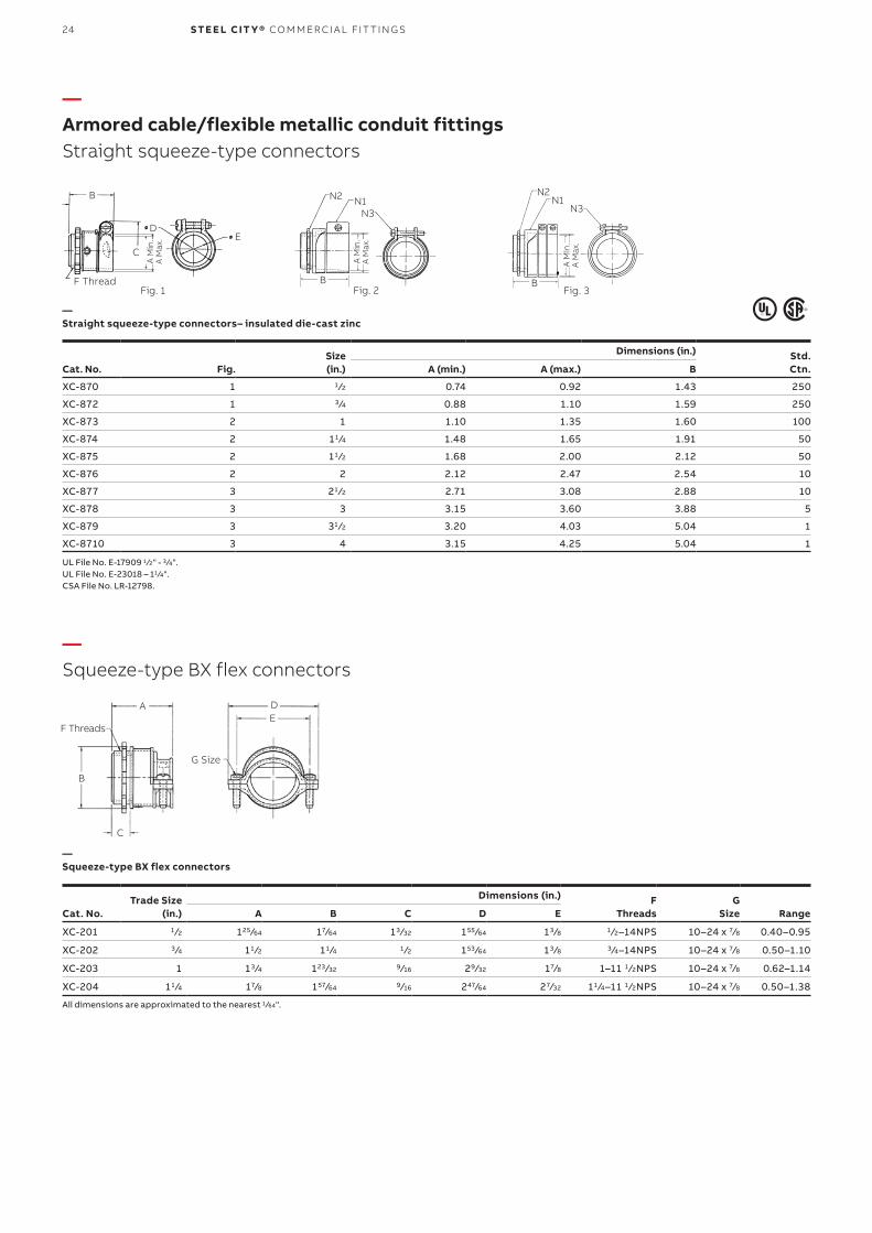
—Armored cable/flexible metallic conduit fittingsStraight squeeze-type connectors
—Squeeze-type BX flex connectors
Fig.Size(in.)
Dimensions (in.) Std.Ctn.Cat. No. A (min.) A (max.) B
XC-870 1 1 ⁄2 0.74 0.92 1.43 250
XC-872 1 3 ⁄4 0.88 1.10 1.59 250
XC-873 2 1 1.10 1.35 1.60 100
XC-874 2 11 ⁄4 1.48 1.65 1.91 50
XC-875 2 11 ⁄2 1.68 2.00 2.12 50
XC-876 2 2 2.12 2.47 2.54 10
XC-877 3 21 ⁄2 2.71 3.08 2.88 10
XC-878 3 3 3.15 3.60 3.88 5
XC-879 3 31 ⁄2 3.20 4.03 5.04 1
XC-8710 3 4 3.15 4.25 5.04 1
UL File No. E-17909 1 ⁄2" - 3 ⁄4".UL File No. E-23018 – 11 ⁄4".CSA File No. LR-12798.
Trade Size(in.)
Dimensions (in.) F Threads
GSize Range Cat. No. A B C D E
XC-201 1 ⁄2 125 ⁄64 17⁄64 13 ⁄32 155 ⁄64 13 ⁄8 1 ⁄2–14NPS 10–24 x 7⁄8 0.40–0.95
XC-202 3 ⁄4 11 ⁄2 11 ⁄4 1 ⁄2 153 ⁄64 13 ⁄8 3 ⁄4–14NPS 10–24 x 7⁄8 0.50–1.10
XC-203 1 13 ⁄4 123 ⁄32 9 ⁄16 29⁄32 17⁄8 1–11 1 ⁄2NPS 10–24 x 7⁄8 0.62–1.14
XC-204 11 ⁄4 17⁄8 157⁄64 9 ⁄16 247⁄64 27⁄32 11 ⁄4–11 1 ⁄2NPS 10–24 x 7⁄8 0.50–1.38
All dimensions are approximated to the nearest 1 ⁄64".
—Straight squeeze-type connectors– insulated die-cast zinc
—Squeeze-type BX flex connectors
Fig. 3B
N2N1
Fig. 2B
N2 N1N3 N3
Fig. 1
B
F Thread
A M
in.
A M
ax.
A M
in.
A M
ax.
A M
in.
A M
ax.
DE
C
A
B
C
DE
G Size
F Threads
25A R M O R ED C A B L E/FL E X I B L E M E TA L L I C CO N D U IT FIT TI N G S
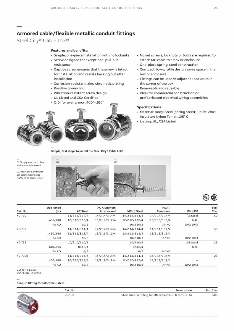
—Armored cable/flexible metallic conduit fittingsSteel City® Cable Lok®
• No set screws, locknuts or tools are required to attach MC cable to a box or enclosure
• One-piece spring-steel construction• Compact, low-profile design saves space in the
box or enclosure• Fittings can be used in adjacent knockouts in
the corner of the box• Removable and reusable• Ideal for commercial construction or
prefabricated electrical wiring assemblies
Specifications:• Material: Body: Steel (spring steel); Finish: Zinc;
Insulator: Nylon; Temp.: 105° C• Listing: UL, CSA Listed
Features and benefits:• Simple, one-piece installation with no locknuts• Screw designed for exceptional pull-out
resistance• Captive screw ensures that the screw is intact
for installation and resists backing out after installation
• Corrosion-resistant, zinc-chromatic plating• Positive grounding• Vibration-resistant screw design• UL Listed and CSA Certified• O.D. for over armor .400"–.510"
—01 Simply snap into place. No locknuts required!— 02 Insert cord and twist set screw. Connectortightens as screw is set.
—02
—01
—Simple, fast steps to install the Steel City® Cable Lok®.
Size Range(in.) AC Steel
AC AluminumInterlocked MC (I) Steel
MC (I) Aluminum Flex RW
Std.Ctn.Cat. No.
XC-730 14/2 14/3 14/4 14/2 14/3 14/4 14/2 14/3 14/4 14/2 14/3 14/4 3 ⁄8 Steel 50
.450/.610 12/2 12/3 12/4 12/2 12/3 12/4 12/2 12/3 12/4 12/2 12/3 12/4 & AL1 ⁄2 KO 10/2 10/2 10/3 1 ⁄2" KO 10/2 10/3
XC-731 14/2 14/3 14/4 14/2 14/3 14/4 14/2 14/3 14/4 14/2 14/3 14/4 50
.450/.610 12/2 12/3 12/4 12/2 12/3 12/4 12/2 12/3 12/4 12/2 12/3 12/4 –1 ⁄2 KO 10/2 10/2 10/3 1 ⁄2" KO 10/2 10/3
XC-732 10/3 10/4 10/5 10/4 10/5 3⁄8 Steel 25
.610/.875 8/3 8/4 – 8/3 8/4 – & AL3 ⁄4 KO 6/2 6/2 3 ⁄4" KO
XC-7300 14/2 14/3 14/4 14/2 14/3 14/4 14/2 14/3 14/4 14/2 14/3 14/4 25
.450/.610 12/2 12/3 12/4 12/2 12/3 12/4 12/2 12/3 12/4 12/2 12/3 12/4 –1 ⁄2 KO 10/2 10/2 10/3 1 ⁄2" KO 10/2 10/3
UL File No. E-1383.CSA File No. LR-12798.
—Snap-in fitting for MC cable – steel
Cat. No. Description Std. Ctn.
XC-130 Steel snap-in fitting for MC cable (14-2+G to 10-3+G) 500
26 S TE E L CIT Y® CO M M ER CI A L FIT TI N G S
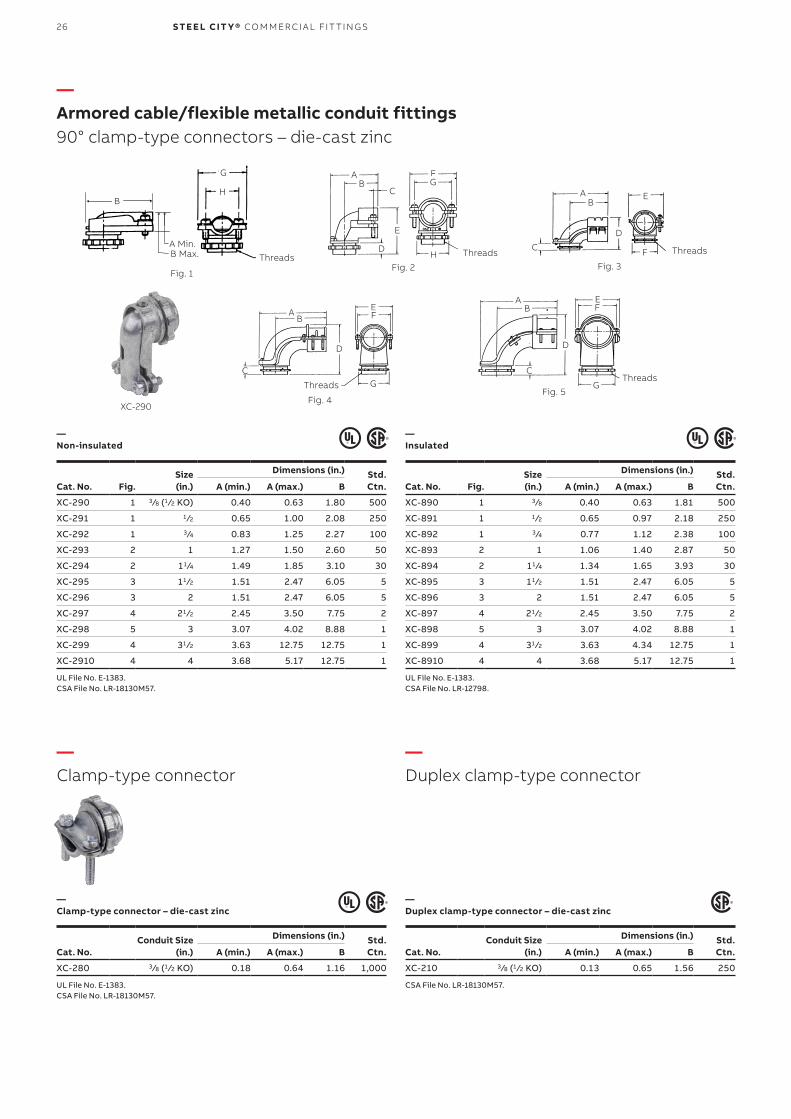
—Armored cable/flexible metallic conduit fittings90° clamp-type connectors – die-cast zinc
—Non-insulated
—Clamp-type connector – die-cast zinc
—Duplex clamp-type connector – die-cast zinc
—Insulated
Fig.Size(in.)
Dimensions (in.) Std.Ctn.Cat. No. A (min.) A (max.) B
XC-290 1 3 ⁄8 (1 ⁄2 KO) 0.40 0.63 1.80 500
XC-291 1 1 ⁄2 0.65 1.00 2.08 250
XC-292 1 3 ⁄4 0.83 1.25 2.27 100
XC-293 2 1 1.27 1.50 2.60 50
XC-294 2 11 ⁄4 1.49 1.85 3.10 30
XC-295 3 11 ⁄2 1.51 2.47 6.05 5
XC-296 3 2 1.51 2.47 6.05 5
XC-297 4 21 ⁄2 2.45 3.50 7.75 2
XC-298 5 3 3.07 4.02 8.88 1
XC-299 4 31 ⁄2 3.63 12.75 12.75 1
XC-2910 4 4 3.68 5.17 12.75 1
UL File No. E-1383.CSA File No. LR-18130M57.
Conduit Size(in.)
Dimensions (in.) Std.Ctn.Cat. No. A (min.) A (max.) B
XC-280 3 ⁄8 (1 ⁄2 KO) 0.18 0.64 1.16 1,000
UL File No. E-1383.CSA File No. LR-18130M57.
Conduit Size(in.)
Dimensions (in.) Std.Ctn.Cat. No. A (min.) A (max.) B
XC-210 3 ⁄8 (1 ⁄2 KO) 0.13 0.65 1.56 250
CSA File No. LR-18130M57.
Fig.Size(in.)
Dimensions (in.) Std.Ctn.Cat. No. A (min.) A (max.) B
XC-890 1 3 ⁄8 0.40 0.63 1.81 500
XC-891 1 1 ⁄2 0.65 0.97 2.18 250
XC-892 1 3 ⁄4 0.77 1.12 2.38 100
XC-893 2 1 1.06 1.40 2.87 50
XC-894 2 11 ⁄4 1.34 1.65 3.93 30
XC-895 3 11 ⁄2 1.51 2.47 6.05 5
XC-896 3 2 1.51 2.47 6.05 5
XC-897 4 21 ⁄2 2.45 3.50 7.75 2
XC-898 5 3 3.07 4.02 8.88 1
XC-899 4 31 ⁄2 3.63 4.34 12.75 1
XC-8910 4 4 3.68 5.17 12.75 1
UL File No. E-1383.CSA File No. LR-12798.
Fig. 1
B
A Min.B Max.
G
H
ThreadsFig. 2
AB
C
D
E
FG
H ThreadsFig. 3
Threads
AB
D
E
FC
Fig. 4
Threads
AB
D
EF
GC
Fig. 5
Threads
AB
C
D
EF
G
—Clamp-type connector
—Duplex clamp-type connector
XC-290
27A R M O R ED C A B L E/FL E X I B L E M E TA L L I C CO N D U IT FIT TI N G S
—Duplex clamp-type connector – die-cast zinc
—Insulated
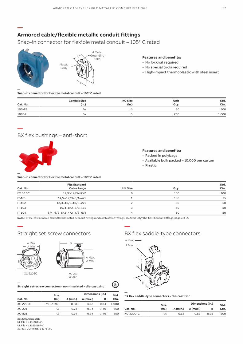
—Snap-in connector for flexible metal conduit – 105° C rated
—Snap-in connector for flexible metal conduit – 105° C rated
Cat. No.Conduit Size
(in.)KO Size
(in.)UnitQty.
Std. Ctn.
100-TB 3 ⁄8 1 ⁄2 50 500
100BP 3 ⁄8 1 ⁄2 250 1,000
Cat. No.Fits Standard
Cable Range Unit Size Qty.Std. Ctn.
IT100 SC 14/2–14/3–12/2 0 100 100
IT-101 14/4–12/3–6/1–4/1 1 100 35
IT-102 12/4–10/2–10/3–2/1 2 50 50
IT-103 10/4–8/2–8/3–1/1 3 50 50
IT-104 8/4–6/2–6/3–4/2–4/3–6/4 4 50 50
Note: For die-cast armored cable/flexible metallic conduit fittings and combination fittings, see Steel City® Die-Cast Conduit Fittings, pages 33-35.
—Armored cable/flexible metallic conduit fittingsSnap-in connector for flexible metal conduit – 105° C rated
—BX flex bushings – anti-short
—Straight set-screw connectors
—BX flex saddle-type connectors
4 Metal Grounding
Tabs
Plastic Body
A
B
C
Features and benefits:• No locknut required• No special tools required• High-impact thermoplastic with steel insert
Features and benefits:• Packed in polybags• Available bulk packed – 10,000 per carton• Plastic
—Straight set-screw connectors - non-insulated – die-cast zinc
—BX flex saddle-type connectors – die-cast zincSize
(in.)
Dimensions (in.) Std.Ctn.Cat. No. A (min.) A (max.) B
XC-220SC 3 ⁄8 (1 ⁄2 KO) 0.38 0.63 0.84 1,000
XC-221 1 ⁄2 0.74 0.94 1.46 250
XC-821 1 ⁄2 0.74 0.94 1.46 250
XC-220 and XC-221: UL File No. E-1383 3 ⁄8".UL File No. E-23018 1 ⁄2".XC-821: UL File No. E-1275 1 ⁄2".
Size(in.)
Dimensions (in.) Std.Ctn.Cat. No. A (min.) A (max.) B
XC-2200-C 3 ⁄8 0.12 0.63 0.98 500
A Max. A Min.
A Max. A Min.
B
XC-221XC-821
XC-220SC
B
A Max.
A Min.
B
28 S TE E L CIT Y® CO M M ER CI A L FIT TI N G S
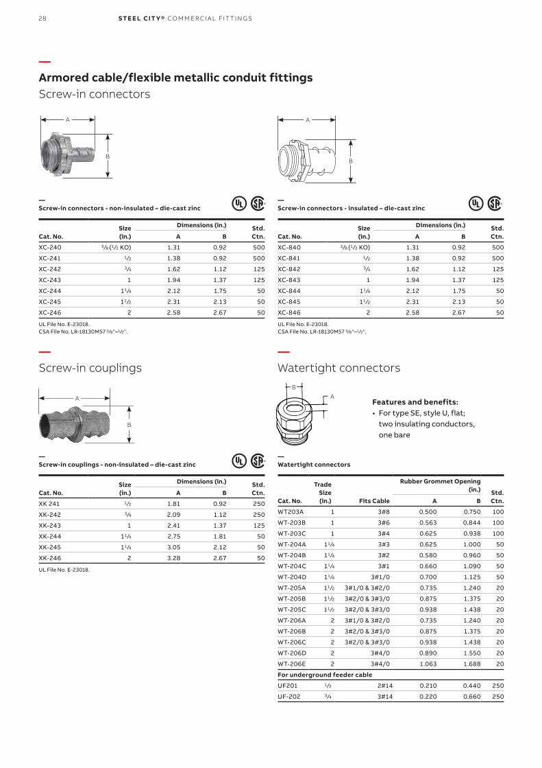
—Armored cable/flexible metallic conduit fittingsScrew-in connectors
—Screw-in couplings
—Watertight connectors
—Screw-in connectors - non-insulated – die-cast zinc
—Screw-in connectors - insulated – die-cast zinc
—Screw-in couplings - non-insulated – die-cast zinc
—Watertight connectors
Size(in.)
Dimensions (in.) Std.Ctn.Cat. No. A B
XC-240 3 ⁄8 (1 ⁄2 KO) 1.31 0.92 500
XC-241 1 ⁄2 1.38 0.92 500
XC-242 3 ⁄4 1.62 1.12 125
XC-243 1 1.94 1.37 125
XC-244 11 ⁄4 2.12 1.75 50
XC-245 11 ⁄2 2.31 2.13 50
XC-246 2 2.58 2.67 50
UL File No. E-23018.CSA File No. LR-18130M57 3 ⁄8"–1 ⁄2".
Size(in.)
Dimensions (in.) Std.Ctn.Cat. No. A B
XC-840 3 ⁄8 (1 ⁄2 KO) 1.31 0.92 500
XC-841 1 ⁄2 1.38 0.92 500
XC-842 3 ⁄4 1.62 1.12 125
XC-843 1 1.94 1.37 125
XC-844 11 ⁄4 2.12 1.75 50
XC-845 11 ⁄2 2.31 2.13 50
XC-846 2 2.58 2.67 50
UL File No. E-23018.CSA File No. LR-18130M57 3 ⁄8"–1 ⁄2".
Size(in.)
Dimensions (in.) Std.Ctn.Cat. No. A B
XK 241 1 ⁄2 1.81 0.92 250
XK-242 3 ⁄4 2.09 1.12 250
XK-243 1 2.41 1.37 125
XK-244 11 ⁄4 2.75 1.81 50
XK-245 11 ⁄4 3.05 2.12 50
XK-246 2 3.28 2.67 50
UL File No. E-23018.
Trade Size(in.)
Rubber Grommet Opening (in.) Std.
Ctn.Cat. No. Fits Cable A B
WT203A 1 3#8 0.500 0.750 100
WT-203B 1 3#6 0.563 0.844 100
WT-203C 1 3#4 0.625 0.938 100
WT-204A 11 ⁄4 3#3 0.625 1.000 50
WT-204B 11 ⁄4 3#2 0.580 0.960 50
WT-204C 11 ⁄4 3#1 0.660 1.090 50
WT-204D 11 ⁄4 3#1/0 0.700 1.125 50
WT-205A 11 ⁄2 3#1/0 & 3#2/0 0.735 1.240 20
WT-205B 11 ⁄2 3#2/0 & 3#3/0 0.875 1.375 20
WT-205C 11 ⁄2 3#2/0 & 3#3/0 0.938 1.438 20
WT-206A 2 3#1/0 & 3#2/0 0.735 1.240 20
WT-206B 2 3#2/0 & 3#3/0 0.875 1.375 20
WT-206C 2 3#2/0 & 3#3/0 0.938 1.438 20
WT-206D 2 3#4/0 0.890 1.550 20
WT-206E 2 3#4/0 1.063 1.688 20
For underground feeder cable
UF201 1 ⁄2 2#14 0.210 0.440 250
UF-202 3 ⁄4 3#14 0.220 0.660 250
B
A
A
B
A
B
A
B
AB
Features and benefits:• For type SE, style U, flat;
two insulating conductors, one bare
29
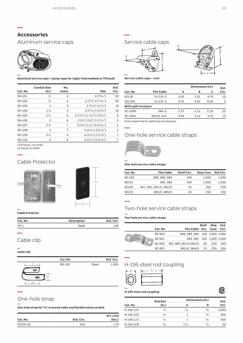
—AccessoriesAluminum service caps
—One-hole service cable straps
—Two-hole service cable straps
—H-195 steel rod coupling
—Service cable caps
—Cable Protector
—Aluminum service caps – clamp-type for rigid/ intermediate or Thinwall
—Cable Protector —
Two-hole service cable straps
—One-hole service cable straps
Conduit Size(in.)
No. Holes Size
Std.Ctn.Cat. No.
SH-101 1 ⁄2 4 4 (19 ⁄64") 50
SH-102 3 ⁄4 5 2 (3 ⁄8") 3 (13 ⁄32") 50
SH-103 1 5 2 (7⁄16") 3 (1 ⁄2") 10
SH-104 11 ⁄4 5 2 (19 ⁄32") 3 (5 ⁄8") 10
SH-105 11 ⁄2 6 2 (19 ⁄32") 1 (7⁄16") 3 (3 ⁄4") 5
SH-106 2 6 2 (3 ⁄4") 3 (1") 1 (17⁄32") 5
SH-107 21 ⁄2 7 3 (7⁄8") 1 (1") 3 (15 ⁄16") 1
SH-108 3 7 4 (11 ⁄8") 3 (13 ⁄4") 1
SH-109 31 ⁄2 4 4 (13 ⁄4") 2 (11 ⁄8") 1
SH-110 4 4 4 (13 ⁄4") 2 (11 ⁄8") 1
CSA File No. LR-12798.UL File No. E-13938.
Cat. No. Description Std. Ctn.
CP-1 Steel 100
Cat. No. Fits Cable Shelf Ctn. Ship Case Std.Ctn.
SE-100 3#8, 3#6, 3#4 100 1,000 1,000
SE101 3#3, 3#2 100 1,000 1,000
SE102 3#1, 3#0, 3#1/0, 3#2/0 25 250 250
SE103 3#3/0, 3#4/0 25 250 250
Cat. No. Fits CableShelf Ctn.
Ship Case
Std.Ctn.
SE-900 3#8, 3#6, 3#4 100 1,000 1,000
SE-901 3#3, 3#2 100 1,000 1,000
SE-902 3#1, 3#0, 3#1/0 3#2/0 25 250 250
SE-903 3#3/0, 3#4/0 25 250 250
13⁄8"
19⁄16"
—Service cable caps – oval
Fits Cable
Dimensions (in.) Std.Ctn.Cat. No. A B C
50130 To 2/0–3 5.00 3.31 4.75 10
50130A To 4/0–3 6.75 4.62 6.00 5
With split insulator
SC-1000 3#3–2 2.37 2.12 2.25 25
SC-2001 3#3/0–4/0 4.93 3.12 3.75 10
Extra-large body for additional wiring space.
A
B
C
A
C
B
B A
—H-195 steel rod coupling
Rod Size(in.)
Dimensions (in.) Std.Ctn.Cat. No. A B
H-195-1/4 1 ⁄4 3 ⁄4 3 ⁄8 1,000
H-195-3/8 3 ⁄8 1 1 ⁄2 500
H-195-1/2 1 ⁄2 1 5 ⁄8 500
H-195-5/8 5 ⁄8 11 ⁄2 3 ⁄4 50
—One-hole strap —One-hole strap for 3⁄8" armored cable and flexible metal conduit
Cat. No. Std. Ctn.WT./100
(lbs.)
FS100-SC 250 1.70
—Cable clip—Cable clip
Cat. No. Std. Ctn.
NS 100 Steel 1,0001"
11⁄8"
3⁄8"
ACCE SSO R IE S
30 S TE E L CIT Y® CO M M ER CI A L FIT TI N G S
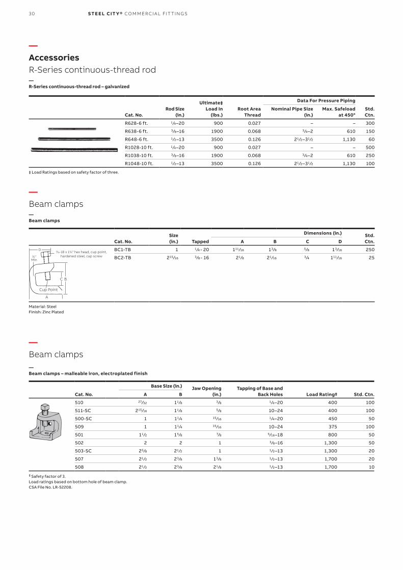
—AccessoriesR-Series continuous-thread rod
—Beam clamps
—R-Series continuous-thread rod – galvanized
Ultimate‡Load In
(lbs.)
Data For Pressure Piping
Cat. No.Rod Size
(in.)Root Area
ThreadNominal Pipe Size
(in.)Max. Safeload
at 450°Std.Ctn.
R628-6 ft. 1 ⁄4–20 900 0.027 – – 300
R638-6 ft. 3 ⁄8–16 1900 0.068 3 ⁄4–2 610 150
R648-6 ft. 1 ⁄2–13 3500 0.126 21 ⁄2–31 ⁄2 1,130 60
R1028-10 ft. 1 ⁄4–20 900 0.027 – – 500
R1038-10 ft. 3 ⁄8–16 1900 0.068 3 ⁄4–2 610 250
R1048-10 ft. 1 ⁄2–13 3500 0.126 21 ⁄2–31 ⁄2 1,130 100
‡ Load Ratings based on safety factor of three.
—Beam clamps
Size (in.)
Dimensions (in.) Std.Ctn.Cat. No. Tapped A B C D
BC1-TB 1 1 ⁄4 - 20 111 ⁄16 13 ⁄8 5 ⁄8 13 ⁄16 250
BC2-TB 215 ⁄16 3 ⁄8 - 16 21 ⁄8 21 ⁄16 3 ⁄4 111 ⁄16 25
Material: SteelFinish: Zinc Plated
3⁄8"Min
D
A
C B
Cup Point
5⁄16-18 x 13⁄8" hex head, cup point, hardened steel, cap screw
—Beam clamps—Beam clamps – malleable iron, electroplated finish
Base Size (in.) Jaw Opening(in.)
Tapping of Base and Back Holes Std. Ctn.Cat. No. A B Load Rating‡
510 27⁄32 11 ⁄8 3 ⁄8 1 ⁄4–20 400 100
511-SC 215 ⁄16 11 ⁄8 5 ⁄8 10–24 400 100
500-SC 1 11 ⁄4 15 ⁄16 1 ⁄4–20 450 50
509 1 11 ⁄4 15 ⁄16 10–24 375 100
501 11 ⁄2 15 ⁄8 7⁄8 5 ⁄16–18 800 50
502 2 2 1 3 ⁄8–16 1,300 50
503-SC 25 ⁄8 21 ⁄2 1 1 ⁄2–13 1,300 20
507 21 ⁄2 23 ⁄8 13 ⁄8 1 ⁄2–13 1,700 20
508 21 ⁄2 23 ⁄8 21 ⁄8 1 ⁄2–13 1,700 10
‡ Safety factor of 3.Load ratings based on bottom hole of beam clamp.CSA File No. LR-52208.
31ACCE SSO R IE S
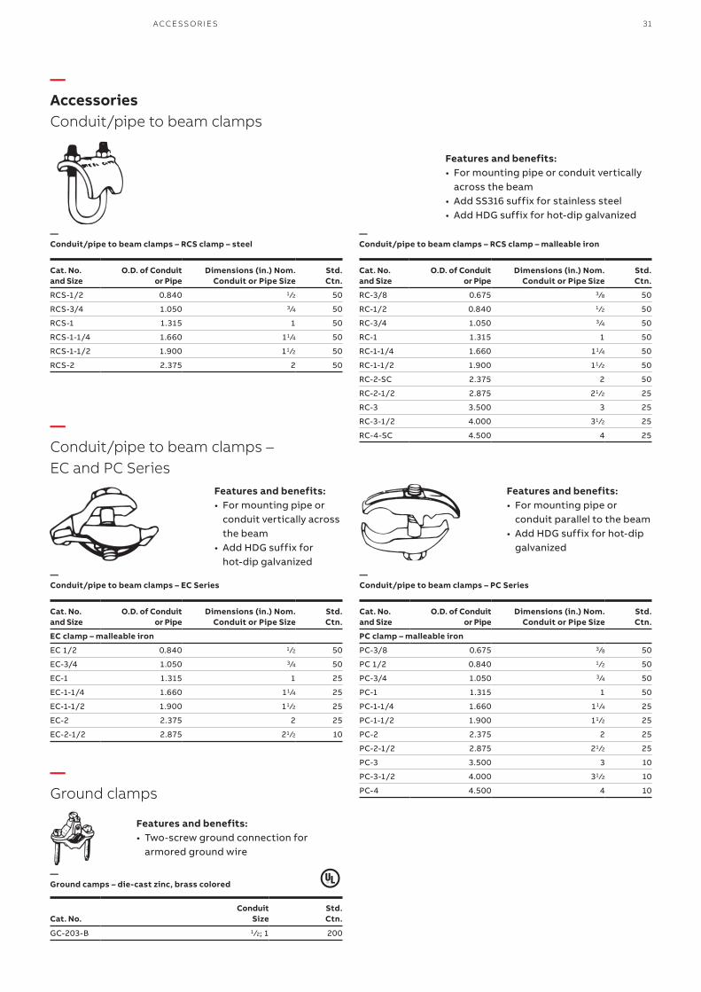
—AccessoriesConduit/pipe to beam clamps
—Ground clamps
—Conduit/pipe to beam clamps – EC and PC Series
—Conduit/pipe to beam clamps – RCS clamp – steel
—Ground camps – die-cast zinc, brass colored
—Conduit/pipe to beam clamps – RCS clamp – malleable iron
—Conduit/pipe to beam clamps – EC Series
—Conduit/pipe to beam clamps – PC Series
Cat. No. and Size
O.D. of Conduitor Pipe
Dimensions (in.) Nom.Conduit or Pipe Size
Std.Ctn.
RCS-1/2 0.840 1 ⁄2 50
RCS-3/4 1.050 3 ⁄4 50
RCS-1 1.315 1 50
RCS-1-1/4 1.660 11 ⁄4 50
RCS-1-1/2 1.900 11 ⁄2 50
RCS-2 2.375 2 50
Cat. No. and Size
O.D. of Conduitor Pipe
Dimensions (in.) Nom.Conduit or Pipe Size
Std.Ctn.
RC-3/8 0.675 3 ⁄8 50
RC-1/2 0.840 1 ⁄2 50
RC-3/4 1.050 3 ⁄4 50
RC-1 1.315 1 50
RC-1-1/4 1.660 11 ⁄4 50
RC-1-1/2 1.900 11 ⁄2 50
RC-2-SC 2.375 2 50
RC-2-1/2 2.875 21 ⁄2 25
RC-3 3.500 3 25
RC-3-1/2 4.000 31 ⁄2 25
RC-4-SC 4.500 4 25
Cat. No. and Size
O.D. of Conduitor Pipe
Dimensions (in.) Nom.Conduit or Pipe Size
Std.Ctn.
EC clamp – malleable iron
EC 1/2 0.840 1 ⁄2 50
EC-3/4 1.050 3 ⁄4 50
EC-1 1.315 1 25
EC-1-1/4 1.660 11 ⁄4 25
EC-1-1/2 1.900 11 ⁄2 25
EC-2 2.375 2 25
EC-2-1/2 2.875 21 ⁄2 10
ConduitSize
Std.Ctn.Cat. No.
GC-203-B 1 ⁄2; 1 200
Cat. No. and Size
O.D. of Conduitor Pipe
Dimensions (in.) Nom.Conduit or Pipe Size
Std.Ctn.
PC clamp – malleable iron
PC-3/8 0.675 3 ⁄8 50
PC 1/2 0.840 1 ⁄2 50
PC-3/4 1.050 3 ⁄4 50
PC-1 1.315 1 50
PC-1-1/4 1.660 11 ⁄4 25
PC-1-1/2 1.900 11 ⁄2 25
PC-2 2.375 2 25
PC-2-1/2 2.875 21 ⁄2 25
PC-3 3.500 3 10
PC-3-1/2 4.000 31 ⁄2 10
PC-4 4.500 4 10
Features and benefits:• For mounting pipe or
conduit parallel to the beam• Add HDG suffix for hot-dip
galvanized
Features and benefits:• For mounting pipe or
conduit vertically across the beam
• Add HDG suffix for hot-dip galvanized
Features and benefits:• For mounting pipe or conduit vertically
across the beam• Add SS316 suffix for stainless steel • Add HDG suffix for hot-dip galvanized
Features and benefits:• Two-screw ground connection for
armored ground wire
32 S TE E L CIT Y® CO M M ER CI A L FIT TI N G S
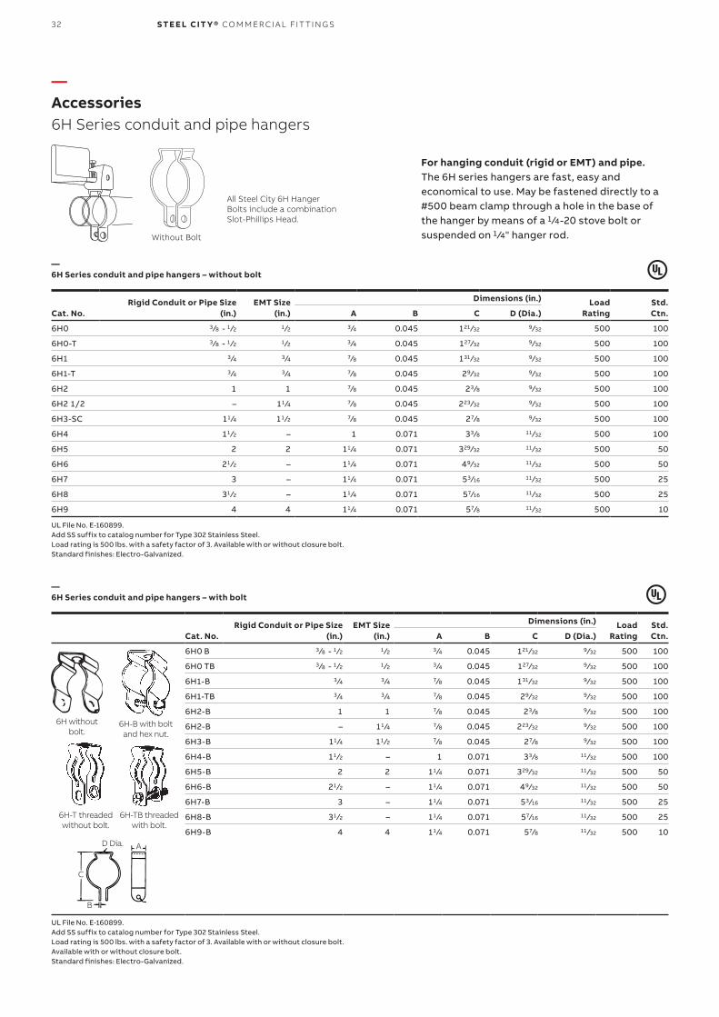
—Accessories6H Series conduit and pipe hangers
For hanging conduit (rigid or EMT) and pipe.The 6H series hangers are fast, easy and economical to use. May be fastened directly to a #500 beam clamp through a hole in the base of the hanger by means of a 1 ⁄4-20 stove bolt or suspended on 1 ⁄4" hanger rod.
Rigid Conduit or Pipe Size(in.)
EMT Size(in.)
Dimensions (in.) LoadRating
Std. Ctn.Cat. No. A B C D (Dia.)
6H0 3 ⁄8 - 1 ⁄2 1 ⁄2 3 ⁄4 0.045 121 ⁄32 9 ⁄32 500 100
6H0-T 3 ⁄8 - 1 ⁄2 1 ⁄2 3 ⁄4 0.045 127⁄32 9 ⁄32 500 100
6H1 3 ⁄4 3 ⁄4 7⁄8 0.045 131 ⁄32 9 ⁄32 500 100
6H1-T 3 ⁄4 3 ⁄4 7⁄8 0.045 29⁄32 9 ⁄32 500 100
6H2 1 1 7⁄8 0.045 23 ⁄8 9 ⁄32 500 100
6H2 1/2 – 11 ⁄4 7⁄8 0.045 223 ⁄32 9 ⁄32 500 100
6H3-SC 11 ⁄4 11 ⁄2 7⁄8 0.045 27⁄8 9 ⁄32 500 100
6H4 11 ⁄2 – 1 0.071 33 ⁄8 11 ⁄32 500 100
6H5 2 2 11 ⁄4 0.071 329⁄32 11 ⁄32 500 50
6H6 21 ⁄2 – 11 ⁄4 0.071 49⁄32 11 ⁄32 500 50
6H7 3 – 11 ⁄4 0.071 53 ⁄16 11 ⁄32 500 25
6H8 31 ⁄2 – 11 ⁄4 0.071 57⁄16 11 ⁄32 500 25
6H9 4 4 11 ⁄4 0.071 57⁄8 11 ⁄32 500 10
Rigid Conduit or Pipe Size(in.)
EMT Size(in.)
Dimensions (in.) LoadRating
Std. Ctn.Cat. No. A B C D (Dia.)
6H0 B 3 ⁄8 - 1 ⁄2 1 ⁄2 3 ⁄4 0.045 121 ⁄32 9 ⁄32 500 100
6H0 TB 3 ⁄8 - 1 ⁄2 1 ⁄2 3 ⁄4 0.045 127⁄32 9 ⁄32 500 100
6H1-B 3 ⁄4 3 ⁄4 7⁄8 0.045 131 ⁄32 9 ⁄32 500 100
6H1-TB 3 ⁄4 3 ⁄4 7⁄8 0.045 29⁄32 9 ⁄32 500 100
6H2-B 1 1 7⁄8 0.045 23 ⁄8 9 ⁄32 500 100
6H2-B – 11 ⁄4 7⁄8 0.045 223 ⁄32 9 ⁄32 500 100
6H3-B 11 ⁄4 11 ⁄2 7⁄8 0.045 27⁄8 9 ⁄32 500 100
6H4-B 11 ⁄2 – 1 0.071 33 ⁄8 11 ⁄32 500 100
6H5-B 2 2 11 ⁄4 0.071 329⁄32 11 ⁄32 500 50
6H6-B 21 ⁄2 – 11 ⁄4 0.071 49⁄32 11 ⁄32 500 50
6H7-B 3 – 11 ⁄4 0.071 53 ⁄16 11 ⁄32 500 25
6H8-B 31 ⁄2 – 11 ⁄4 0.071 57⁄16 11 ⁄32 500 25
6H9-B 4 4 11 ⁄4 0.071 57⁄8 11 ⁄32 500 10
—6H Series conduit and pipe hangers – without bolt
—6H Series conduit and pipe hangers – with bolt
All Steel City 6H Hanger Bolts include a combination Slot-Phillips Head.
Without Bolt
UL File No. E-160899.Add SS suffix to catalog number for Type 302 Stainless Steel.Load rating is 500 lbs. with a safety factor of 3. Available with or without closure bolt.Standard finishes: Electro-Galvanized.
UL File No. E-160899.Add SS suffix to catalog number for Type 302 Stainless Steel.Load rating is 500 lbs. with a safety factor of 3. Available with or without closure bolt.Available with or without closure bolt. Standard finishes: Electro-Galvanized.
6H without bolt.
6H-B with bolt and hex nut.
6H-T threaded without bolt.
6H-TB threaded with bolt.
�D Dia. A
B
C
33
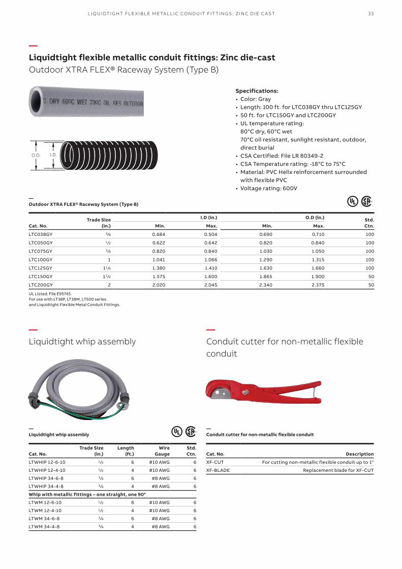
—Liquidtight flexible metallic conduit fittings: Zinc die-castOutdoor XTRA FLEX® Raceway System (Type B)
Trade Size(in.)
I.D (in.) O.D (in.) Std. Ctn.Cat. No. Min. Max. Min. Max.
LTC038GY 3 ⁄8 0.484 0.504 0.690 0.710 100
LTC050GY 1 ⁄2 0.622 0.642 0.820 0.840 100
LTC075GY 3 ⁄4 0.820 0.840 1.030 1.050 100
LTC100GY 1 1.041 1.066 1.290 1.315 100
LTC125GY 11 ⁄4 1.380 1.410 1.630 1.660 100
LTC150GY 11 ⁄2 1.575 1.600 1.865 1.900 50
LTC200GY 2 2.020 2.045 2.340 2.375 50
—Outdoor XTRA FLEX® Raceway System (Type B)
O.D. I.D.
Specifications:• Color: Gray• Length: 100 ft. for LTC038GY thru LTC125GY• 50 ft. for LTC150GY and LTC200GY• UL temperature rating:
80°C dry, 60°C wet 70°C oil resistant, sunlight resistant, outdoor, direct burial
• CSA Certified: File LR 80349-2• CSA Temperature rating: -18°C to 75°C• Material: PVC Helix reinforcement surrounded
with flexible PVC• Voltage rating: 600V
UL Listed: File E95745.For use with LT38P, LT38M, LT500 seriesand Liquidtight Flexible Metal Conduit Fittings.
—Liquidtight whip assembly
—Conduit cutter for non-metallic flexible conduit
—Liquidtight whip assembly
—Conduit cutter for non-metallic flexible conduit
Cat. No.Trade Size
(in.)Length
(ft.)Wire
GaugeStd. Ctn.
LTWHIP 12-6-10 1 ⁄2 6 #10 AWG 6
LTWHIP 12-4-10 1 ⁄2 4 #10 AWG 6
LTWHIP 34-6-8 3 ⁄4 6 #8 AWG 6
LTWHIP 34-4-8 3 ⁄4 4 #8 AWG 6
Whip with metallic fittings – one straight, one 90°
LTWM 12-6-10 1 ⁄2 6 #10 AWG 6
LTWM 12-4-10 1 ⁄2 4 #10 AWG 6
LTWM 34-6-8 3 ⁄4 6 #8 AWG 6
LTWM 34-4-8 3 ⁄4 4 #8 AWG 6
Cat. No. Description
XF-CUT For cutting non-metallic flexible conduit up to 1"
XF-BLADE Replacement blade for XF-CUT
L I Q U I DTI G HT FL E X I B L E M E TA L L I C CO N D U IT FIT TI N G S: ZI N C D I E C A S T
34 S TE E L CIT Y® CO M M ER CI A L FIT TI N G S
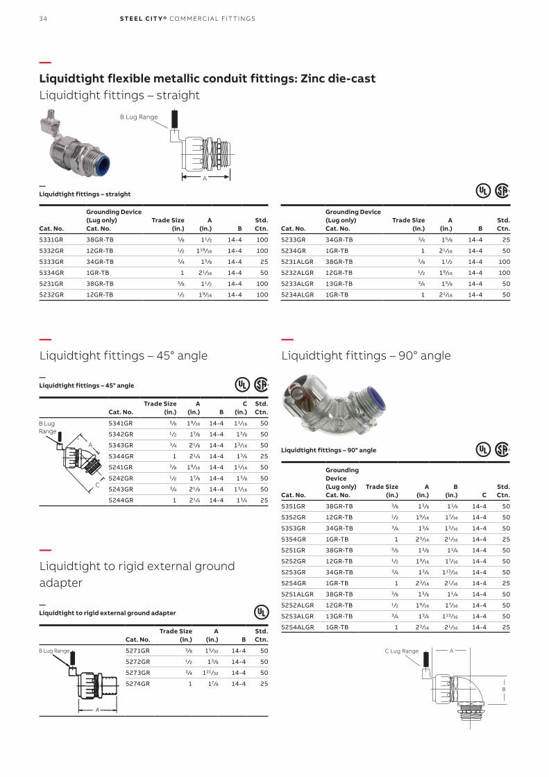
—Liquidtight flexible metallic conduit fittings: Zinc die-castLiquidtight fittings – straight
—Liquidtight fittings – 45° angle
—Liquidtight to rigid external ground adapter
—Liquidtight fittings – 90° angle
—Liquidtight fittings – straight
—Liquidtight fittings – 45° angle
—Liquidtight to rigid external ground adapter
—Liquidtight fittings – 90° angle
Cat. No.
Grounding Device(Lug only)Cat. No.
Trade Size(in.)
A(in.) B
Std. Ctn.
5331GR 38GR-TB 3 ⁄8 11 ⁄2 14-4 100
5332GR 12GR-TB 1 ⁄2 119 ⁄16 14-4 100
5333GR 34GR-TB 3 ⁄4 15 ⁄8 14-4 25
5334GR 1GR-TB 1 21 ⁄16 14-4 50
5231GR 38GR-TB 3 ⁄8 11 ⁄2 14-4 100
5232GR 12GR-TB 1 ⁄2 19⁄16 14-4 100
Cat. No.Trade Size
(in.)A
(in.) BC
(in.)Std. Ctn.
5341GR 3 ⁄8 19⁄16 14-4 11 ⁄16 50
5342GR 1 ⁄2 17⁄8 14-4 13 ⁄8 50
5343GR 3 ⁄4 21 ⁄8 14-4 13 ⁄16 50
5344GR 1 21 ⁄4 14-4 13 ⁄4 25
5241GR 3 ⁄8 19⁄16 14-4 11 ⁄16 50
5242GR 1 ⁄2 17⁄8 14-4 13 ⁄8 50
5243GR 3 ⁄4 21 ⁄8 14-4 13 ⁄16 50
5244GR 1 21 ⁄4 14-4 13 ⁄4 25
Cat. No.Trade Size
(in.)A
(in.) BStd. Ctn.
5271GR 3 ⁄8 15 ⁄32 14-4 50
5272GR 1 ⁄2 13 ⁄8 14-4 50
5273GR 3 ⁄4 121 ⁄32 14-4 50
5274GR 1 17⁄8 14-4 25
Cat. No.
Grounding Device(Lug only)Cat. No.
Trade Size(in.)
A(in.) B
Std. Ctn.
5233GR 34GR-TB 3 ⁄4 15 ⁄8 14-4 25
5234GR 1GR-TB 1 21 ⁄16 14-4 50
5231ALGR 38GR-TB 3 ⁄8 11 ⁄2 14-4 100
5232ALGR 12GR-TB 1 ⁄2 19⁄16 14-4 100
5233ALGR 13GR-TB 3 ⁄4 15 ⁄8 14-4 50
5234ALGR 1GR-TB 1 21 ⁄16 14-4 50
Cat. No.
Grounding Device(Lug only)Cat. No.
Trade Size(in.)
A(in.)
B(in.) C
Std. Ctn.
5351GR 38GR-TB 3 ⁄8 13 ⁄8 11 ⁄4 14-4 50
5352GR 12GR-TB 1 ⁄2 19⁄16 17⁄16 14-4 50
5353GR 34GR-TB 3 ⁄4 13 ⁄4 13 ⁄16 14-4 50
5354GR 1GR-TB 1 23 ⁄16 21 ⁄16 14-4 25
5251GR 38GR-TB 3 ⁄8 13 ⁄8 11 ⁄4 14-4 50
5252GR 12GR-TB 1 ⁄2 19⁄16 17⁄16 14-4 50
5253GR 34GR-TB 3 ⁄4 13 ⁄4 113 ⁄16 14-4 50
5254GR 1GR-TB 1 23 ⁄16 21 ⁄16 14-4 25
5251ALGR 38GR-TB 3 ⁄8 13 ⁄8 11 ⁄4 14-4 50
5252ALGR 12GR-TB 1 ⁄2 19⁄16 17⁄16 14-4 50
5253ALGR 13GR-TB 3 ⁄4 13 ⁄4 113 ⁄16 14-4 50
5254ALGR 1GR-TB 1 23 ⁄16 21 ⁄16 14-4 25
B Lug Range
A
C Lug Range A
B
AA
B Lug Range
A
C
A
C
B Lug Range
35L I Q U I DTI G HT FL E X I B L E M E TA L L I C CO N D U IT FIT TI N G S: ZI N C D I E C A S T
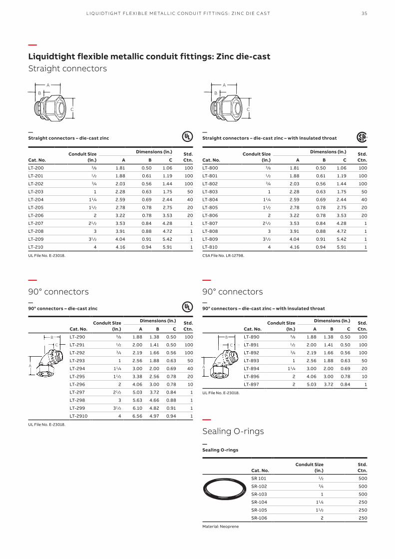
—Liquidtight flexible metallic conduit fittings: Zinc die-castStraight connectors
—90° connectors
—90° connectors
—Sealing O-rings
—Straight connectors – die-cast zinc
—90° connectors – die-cast zinc
—90° connectors – die-cast zinc – with insulated throat
—Sealing O-rings
—Straight connectors – die-cast zinc – with insulated throat
Conduit Size(in.)
Dimensions (in.) Std.Ctn.Cat. No. A B C
LT-200 3 ⁄8 1.81 0.50 1.06 100
LT-201 1 ⁄2 1.88 0.61 1.19 100
LT-202 3 ⁄4 2.03 0.56 1.44 100
LT-203 1 2.28 0.63 1.75 50
LT-204 11 ⁄4 2.59 0.69 2.44 40
LT-205 11 ⁄2 2.78 0.78 2.75 20
LT-206 2 3.22 0.78 3.53 20
LT-207 21 ⁄2 3.53 0.84 4.28 1
LT-208 3 3.91 0.88 4.72 1
LT-209 31 ⁄2 4.04 0.91 5.42 1
LT-210 4 4.16 0.94 5.91 1
UL File No. E-23018.
Conduit Size(in.)
Dimensions (in.) Std.Ctn.Cat. No. A B C
LT-290 3 ⁄8 1.88 1.38 0.50 100
LT-291 1 ⁄2 2.00 1.41 0.50 100
LT-292 3 ⁄4 2.19 1.66 0.56 100
LT-293 1 2.56 1.88 0.63 50
LT-294 11 ⁄4 3.00 2.00 0.69 40
LT-295 11 ⁄2 3.38 2.56 0.78 20
LT-296 2 4.06 3.00 0.78 10
LT-297 21 ⁄2 5.03 3.72 0.84 1
LT-298 3 5.63 4.66 0.88 1
LT-299 31 ⁄2 6.10 4.82 0.91 1
LT-2910 4 6.56 4.97 0.94 1
UL File No. E-23018.
Conduit Size(in.)
Dimensions (in.) Std.Ctn.Cat. No. A B C
LT-890 3 ⁄8 1.88 1.38 0.50 100
LT-891 1 ⁄2 2.00 1.41 0.50 100
LT-892 3 ⁄4 2.19 1.66 0.56 100
LT-893 1 2.56 1.88 0.63 50
LT-894 11 ⁄4 3.00 2.00 0.69 20
LT-896 2 4.06 3.00 0.78 10
LT-897 2 5.03 3.72 0.84 1
UL File No. E-23018.
Conduit Size(in.)
Std.Ctn.Cat. No.
SR 101 1 ⁄2 500
SR-102 3 ⁄4 500
SR-103 1 500
SR-104 11 ⁄4 250
SR-105 11 ⁄2 250
SR-106 2 250
Material: Neoprene
Conduit Size(in.)
Dimensions (in.) Std.Ctn.Cat. No. A B C
LT-800 3 ⁄8 1.81 0.50 1.06 100
LT-801 1 ⁄2 1.88 0.61 1.19 100
LT-802 3 ⁄4 2.03 0.56 1.44 100
LT-803 1 2.28 0.63 1.75 50
LT-804 11 ⁄4 2.59 0.69 2.44 40
LT-805 11 ⁄2 2.78 0.78 2.75 20
LT-806 2 3.22 0.78 3.53 20
LT-807 21 ⁄2 3.53 0.84 4.28 1
LT-808 3 3.91 0.88 4.72 1
LT-809 31 ⁄2 4.04 0.91 5.42 1
LT-810 4 4.16 0.94 5.91 1
CSA File No. LR-12798.
A A
B B
C C
A
B
C
A
B
C
36 S TE E L CIT Y® CO M M ER CI A L FIT TI N G S
Part No. GID CodePage
No.
501 7TAA015030R0003 30
502 7TAA015030R0005 30
507 7TAA015030R0008 30
508 7TAA015030R0009 30
509 7TAA015030R0011 30
510 7TAA015030R0012 30
3202 7TAA011520R0004 21
3300 7TAA011520R0005 21
50130 — 29
100-TB 7TAA011070R0000 27
100BP 7TAA011070R0001 27
12GR-TB 7TAD012310R0000 34
12GR-TB 7TAD012310R0000 34
12GR-TB 7TAD012310R0000 34
12GR-TB 7TAD012310R0000 34
12GR-TB 7TAD012310R0000 34
12GR-TB 7TAD012310R0000 34
13GR-TB — 34
13GR-TB — 34
1GR-TB 7TAD012410R0003 34
1GR-TB 7TAD012410R0003 34
1GR-TB 7TAD012410R0003 34
1GR-TB 7TAD012410R0003 34
1GR-TB 7TAD012410R0003 34
1GR-TB 7TAD012410R0003 34
3201-TB 7TAA011510R0002 21
34GR-TB 7TAD012410R0004 34
34GR-TB 7TAD012410R0004 34
34GR-TB 7TAD012410R0004 34
34GR-TB 7TAD012410R0004 34
38GR-TB 7TAD012410R0005 34
38GR-TB 7TAD012410R0005 34
38GR-TB 7TAD012410R0005 34
38GR-TB 7TAD012410R0005 34
38GR-TB 7TAD012410R0005 34
38GR-TB 7TAD012410R0005 34
500-SC 7TAA015030R0001 30
50130A — 29
503-SC 7TAA015030R0007 30
511-SC 7TAA015950R0021 30
5231ALGR — 34
5231GR 7TAD012980R0085 34
5232ALGR 7TAD012310R0001 34
5232GR 7TAD012300R0000 34
5233ALGR 7TAD012310R0002 34
5233GR 7TAD012310R0003 34
5234ALGR 7TAD012420R0004 34
5234GR 7TAD012310R0005 34
5241GR 7TAD012420R0011 34
Part No. GID CodePage
No.
5242GR 7TAD012310R0009 34
5243GR 7TAD012310R0010 34
5244GR 7TAD012310R0011 34
5251ALGR — 34
5251GR 7TAD012420R0019 34
5252ALGR 7TAD012310R0014 34
5252GR 7TAD012310R0015 34
5253ALGR 7TAD012420R0021 34
5253GR 7TAD012310R0017 34
5254ALGR 7TAD012420R0022 34
5254GR 7TAD012310R0019 34
5271GR 7TAD012980R0089 34
5272GR 7TAD012420R0030 34
5273GR 7TAD012420R0031 34
5274GR 7TAD012420R0032 34
5331GR 7TAD012420R0042 34
5332GR 7TAD012300R0002 34
5333GR 7TAD012300R0004 34
5334GR 7TAD012300R0006 34
5341GR 7TAD012420R0064 34
5342GR 7TAD012300R0016 34
5343GR 7TAD012300R0018 34
5344GR 7TAD012310R0027 34
5351GR 7TAD012420R0083 34
5352GR 7TAD012300R0022 34
5353GR 7TAD012300R0023 34
5354GR 7TAD012310R0037 34
6H0 7TAA015000R0014 32
6H0 B 7TAA015000R0015 32
6H0-T 7TAA015000R0016 32
6H0-TB 7TAA015000R0017 32
6H1 7TAA015000R0018 32
6H1-B 7TAA015000R0019 32
6H1-T 7TAA015000R0020 32
6H1-TB 7TAA015000R0021 32
6H2 7TAA015000R0022 32
6H2 1/2 7TAA015000R0023 32
6H2-B 7TAA015000R0026 32
6H2-B 7TAA015000R0026 32
6H3-B 7TAA015000R0027 32
6H3-SC 7TAA015000R0028 32
6H4 7TAA015000R0030 32
6H4-B 7TAA015000R0031 32
6H5 7TAA015000R0032 32
6H5-B 7TAA015000R0033 32
6H6 7TAA015000R0034 32
6H6-B 7TAA015000R0035 32
6H7 7TAA015000R0037 32
6H7-B 7TAA015000R0038 32
Part No. GID CodePage
No.
6H8 7TAA015000R0039 32
6H8-B 7TAA015000R0040 32
6H9 7TAA015000R0041 32
6H9-B 7TAA015000R0042 32
841-TB 7TAD013130R0006 15
BC1-TB 7TAA015040R0001 30
BC2-TB 7TAA015040R0003 30
BG- 805A 7TAA010220R0013 18
BG-201 7TAA010220R0000 17
BG-202 7TAA010220R0001 17
BG-203 7TAA010220R0002 17
BG-204 7TAA010220R0003 17
BG-204A 7TAA010230R0000 17
BG-205 7TAA010220R0004 17
BG-205A 7TAA010220R0005 17
BG-206 7TAA010210R0000 17
BG-206A 7TAA010220R0006 17
BG-207 7TAA010220R0007 17
BG-207A 7TAA010230R0001 17
BG-208 7TAA010220R0008 17
BG-208A 7TAA010230R0002 17
BG-209 7TAA010220R0009 17
BG-209A 7TAA010230R0003 17
BG-210 7TAA010210R0001 17
BG-210A 7TAA010220R0010 17
BG-801A 7TAA010230R0004 18
BG-802A 7TAA010220R0011 18
BG-803A 7TAA010220R0012 18
BG-804A 7TAA010230R0005 18
BG-806A 7TAA010220R0014 18
BG-807A 7TAA010220R0015 18
BG-808A 7TAA010220R0016 18
BG-809A 7TAA010230R0006 18
BG-810A 7TAA010220R0017 18
BG-810B 7TAA010230R0007 18
BG801L 7TAA117110R0010 18
BG802L 7TAA117110R0011 18
BG803L 7TAA117110R0012 18
BG804L 7TAA117110R0013 18
BG805L 7TAA117110R0014 18
BG806L 7TAA117110R0015 18
BG807L 7TAA117110R0016 18
BG808L 7TAA117110R0017 18
BG809L 7TAA117110R0018 18
BG810L 7TAA117110R0019 18
BI-901 7TAA117100R0000 18
BI-902 7TAA117100R0001 18
BI-903 7TAA117100R0002 18
BI-904 7TAA117100R0003 18
—Index Order code classification
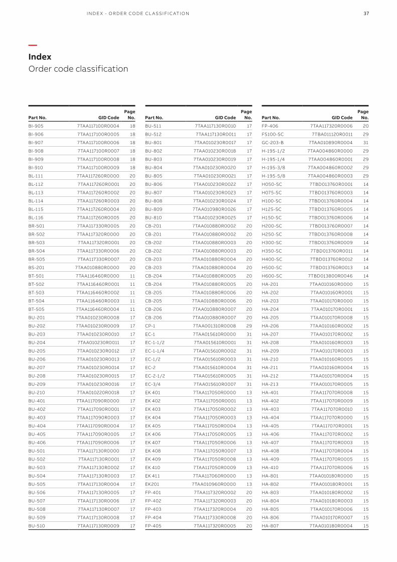
3737I N D E X - O R D ER CO D E CL A SSIFI C ATI O N
—Index Order code classification
Part No. GID CodePage
No.
BU-511 7TAA117130R0010 17
BU-512 7TAA117130R0011 17
BU-801 7TAA010230R0017 17
BU-802 7TAA010230R0018 17
BU-803 7TAA010230R0019 17
BU-804 7TAA010230R0020 17
BU-805 7TAA010230R0021 17
BU-806 7TAA010230R0022 17
BU-807 7TAA010230R0023 17
BU-808 7TAA010230R0024 17
BU-809 7TAA010980R0026 17
BU-810 7TAA010230R0025 17
CB-201 7TAA010880R0002 20
CB-201 7TAA010880R0002 20
CB-202 7TAA010880R0003 20
CB-202 7TAA010880R0003 20
CB-203 7TAA010880R0004 20
CB-203 7TAA010880R0004 20
CB-204 7TAA010880R0005 20
CB-204 7TAA010880R0005 20
CB-205 7TAA010880R0006 20
CB-205 7TAA010880R0006 20
CB-206 7TAA010880R0007 20
CB-206 7TAA010880R0007 20
CP-1 7TAA001310R0008 29
EC-1 7TAA015610R0000 31
EC-1-1/2 7TAA015610R0001 31
EC-1-1/4 7TAA015610R0002 31
EC-1/2 7TAA015610R0003 31
EC-2 7TAA015610R0004 31
EC-2-1/2 7TAA015610R0005 31
EC-3/4 7TAA015610R0007 31
EK 401 7TAA117050R0000 13
EK 402 7TAA117050R0001 13
EK 403 7TAA117050R0002 13
EK 404 7TAA117050R0003 13
EK 405 7TAA117050R0004 13
EK 406 7TAA117050R0005 13
EK 407 7TAA117050R0006 13
EK 408 7TAA117050R0007 13
EK 409 7TAA117050R0008 13
EK 410 7TAA117050R0009 13
EK 411 7TAA117060R0000 13
EK201 7TAA010960R0000 13
FP-401 7TAA117320R0002 20
FP-402 7TAA117320R0003 20
FP-403 7TAA117320R0004 20
FP-404 7TAA117330R0008 20
FP-405 7TAA117320R0005 20
Part No. GID CodePage
No.
BI-905 7TAA117100R0004 18
BI-906 7TAA117100R0005 18
BI-907 7TAA117100R0006 18
BI-908 7TAA117100R0007 18
BI-909 7TAA117100R0008 18
BI-910 7TAA117100R0009 18
BL-111 7TAA117260R0000 20
BL-112 7TAA117260R0001 20
BL-113 7TAA117260R0002 20
BL-114 7TAA117260R0003 20
BL-115 7TAA117260R0004 20
BL-116 7TAA117260R0005 20
BR-501 7TAA117330R0005 20
BR-502 7TAA117320R0000 20
BR-503 7TAA117320R0001 20
BR-504 7TAA117330R0006 20
BR-505 7TAA117330R0007 20
BS-201 7TAA010880R0000 20
BT-501 7TAA116460R0000 11
BT-502 7TAA116460R0001 11
BT-503 7TAA116460R0002 11
BT-504 7TAA116460R0003 11
BT-505 7TAA116460R0004 11
BU-201 7TAA010230R0008 17
BU-202 7TAA010230R0009 17
BU-203 7TAA010230R0010 17
BU-204 7TAA010230R0011 17
BU-205 7TAA010230R0012 17
BU-206 7TAA010230R0013 17
BU-207 7TAA010230R0014 17
BU-208 7TAA010230R0015 17
BU-209 7TAA010230R0016 17
BU-210 7TAA010220R0018 17
BU-401 7TAA117090R0000 17
BU-402 7TAA117090R0001 17
BU-403 7TAA117090R0003 17
BU-404 7TAA117090R0004 17
BU-405 7TAA117090R0005 17
BU-406 7TAA117090R0006 17
BU-501 7TAA117130R0000 17
BU-502 7TAA117130R0001 17
BU-503 7TAA117130R0002 17
BU-504 7TAA117130R0003 17
BU-505 7TAA117130R0004 17
BU-506 7TAA117130R0005 17
BU-507 7TAA117130R0006 17
BU-508 7TAA117130R0007 17
BU-509 7TAA117130R0008 17
BU-510 7TAA117130R0009 17
Part No. GID CodePage
No.
FP-406 7TAA117320R0006 20
FS100-SC 7TBA011120R0011 29
GC-203-B 7TAA010890R0004 31
H-195-1/2 7TAA004860R0000 29
H-195-1/4 7TAA004860R0001 29
H-195-3/8 7TAA004860R0002 29
H-195-5/8 7TAA004860R0003 29
H050-SC 7TBD013760R0001 14
H075-SC 7TBD013760R0003 14
H100-SC 7TBD013760R0004 14
H125-SC 7TBD013760R0005 14
H150-SC 7TBD013760R0006 14
H200-SC 7TBD013760R0007 14
H250-SC 7TBD013760R0008 14
H300-SC 7TBD013760R0009 14
H350-SC 7TBD013760R0011 14
H400-SC 7TBD013760R0012 14
H500-SC 7TBD013760R0013 14
H600-SC 7TBD013800R0046 14
HA-201 7TAA010160R0000 15
HA-202 7TAA010160R0001 15
HA-203 7TAA010170R0000 15
HA-204 7TAA010170R0001 15
HA-205 7TAA010170R0008 15
HA-206 7TAA010160R0002 15
HA-207 7TAA010170R0002 15
HA-208 7TAA010160R0003 15
HA-209 7TAA010170R0003 15
HA-210 7TAA010160R0005 15
HA-211 7TAA010160R0004 15
HA-212 7TAA010170R0004 15
HA-213 7TAA010170R0005 15
HA-401 7TAA117070R0008 15
HA-402 7TAA117070R0009 15
HA-403 7TAA117070R0010 15
HA-404 7TAA117070R0000 15
HA-405 7TAA117070R0001 15
HA-406 7TAA117070R0002 15
HA-407 7TAA117070R0003 15
HA-408 7TAA117070R0004 15
HA-409 7TAA117070R0005 15
HA-410 7TAA117070R0006 15
HA-801 7TAA010180R0000 15
HA-802 7TAA010180R0001 15
HA-803 7TAA010180R0002 15
HA-804 7TAA010180R0003 15
HA-805 7TAA010170R0006 15
HA-806 7TAA010170R0007 15
HA-807 7TAA010180R0004 15
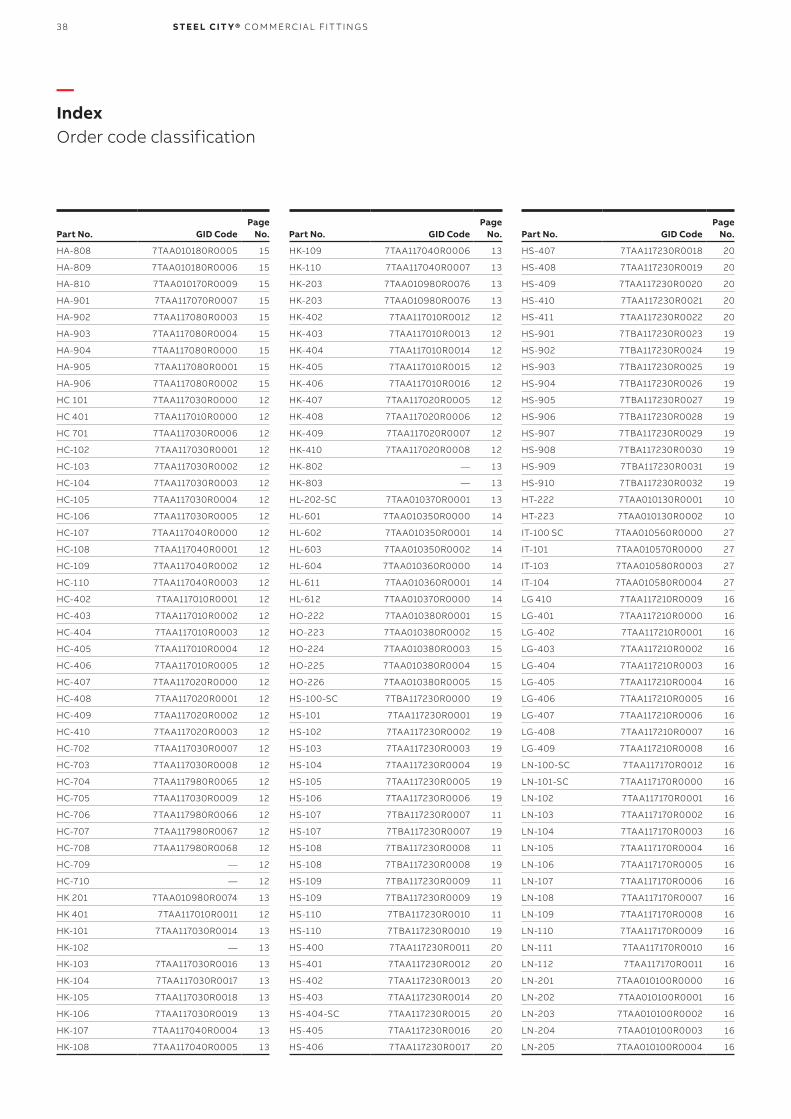
38 S TE E L CIT Y® CO M M ER CI A L FIT TI N G S
—Index Order code classification
Part No. GID CodePage
No.
HA-808 7TAA010180R0005 15
HA-809 7TAA010180R0006 15
HA-810 7TAA010170R0009 15
HA-901 7TAA117070R0007 15
HA-902 7TAA117080R0003 15
HA-903 7TAA117080R0004 15
HA-904 7TAA117080R0000 15
HA-905 7TAA117080R0001 15
HA-906 7TAA117080R0002 15
HC 101 7TAA117030R0000 12
HC 401 7TAA117010R0000 12
HC 701 7TAA117030R0006 12
HC-102 7TAA117030R0001 12
HC-103 7TAA117030R0002 12
HC-104 7TAA117030R0003 12
HC-105 7TAA117030R0004 12
HC-106 7TAA117030R0005 12
HC-107 7TAA117040R0000 12
HC-108 7TAA117040R0001 12
HC-109 7TAA117040R0002 12
HC-110 7TAA117040R0003 12
HC-402 7TAA117010R0001 12
HC-403 7TAA117010R0002 12
HC-404 7TAA117010R0003 12
HC-405 7TAA117010R0004 12
HC-406 7TAA117010R0005 12
HC-407 7TAA117020R0000 12
HC-408 7TAA117020R0001 12
HC-409 7TAA117020R0002 12
HC-410 7TAA117020R0003 12
HC-702 7TAA117030R0007 12
HC-703 7TAA117030R0008 12
HC-704 7TAA117980R0065 12
HC-705 7TAA117030R0009 12
HC-706 7TAA117980R0066 12
HC-707 7TAA117980R0067 12
HC-708 7TAA117980R0068 12
HC-709 — 12
HC-710 — 12
HK 201 7TAA010980R0074 13
HK 401 7TAA117010R0011 12
HK-101 7TAA117030R0014 13
HK-102 — 13
HK-103 7TAA117030R0016 13
HK-104 7TAA117030R0017 13
HK-105 7TAA117030R0018 13
HK-106 7TAA117030R0019 13
HK-107 7TAA117040R0004 13
HK-108 7TAA117040R0005 13
Part No. GID CodePage
No.
HK-109 7TAA117040R0006 13
HK-110 7TAA117040R0007 13
HK-203 7TAA010980R0076 13
HK-203 7TAA010980R0076 13
HK-402 7TAA117010R0012 12
HK-403 7TAA117010R0013 12
HK-404 7TAA117010R0014 12
HK-405 7TAA117010R0015 12
HK-406 7TAA117010R0016 12
HK-407 7TAA117020R0005 12
HK-408 7TAA117020R0006 12
HK-409 7TAA117020R0007 12
HK-410 7TAA117020R0008 12
HK-802 — 13
HK-803 — 13
HL-202-SC 7TAA010370R0001 13
HL-601 7TAA010350R0000 14
HL-602 7TAA010350R0001 14
HL-603 7TAA010350R0002 14
HL-604 7TAA010360R0000 14
HL-611 7TAA010360R0001 14
HL-612 7TAA010370R0000 14
HO-222 7TAA010380R0001 15
HO-223 7TAA010380R0002 15
HO-224 7TAA010380R0003 15
HO-225 7TAA010380R0004 15
HO-226 7TAA010380R0005 15
HS-100-SC 7TBA117230R0000 19
HS-101 7TAA117230R0001 19
HS-102 7TAA117230R0002 19
HS-103 7TAA117230R0003 19
HS-104 7TAA117230R0004 19
HS-105 7TAA117230R0005 19
HS-106 7TAA117230R0006 19
HS-107 7TBA117230R0007 11
HS-107 7TBA117230R0007 19
HS-108 7TBA117230R0008 11
HS-108 7TBA117230R0008 19
HS-109 7TBA117230R0009 11
HS-109 7TBA117230R0009 19
HS-110 7TBA117230R0010 11
HS-110 7TBA117230R0010 19
HS-400 7TAA117230R0011 20
HS-401 7TAA117230R0012 20
HS-402 7TAA117230R0013 20
HS-403 7TAA117230R0014 20
HS-404-SC 7TAA117230R0015 20
HS-405 7TAA117230R0016 20
HS-406 7TAA117230R0017 20
Part No. GID CodePage
No.
HS-407 7TAA117230R0018 20
HS-408 7TAA117230R0019 20
HS-409 7TAA117230R0020 20
HS-410 7TAA117230R0021 20
HS-411 7TAA117230R0022 20
HS-901 7TBA117230R0023 19
HS-902 7TBA117230R0024 19
HS-903 7TBA117230R0025 19
HS-904 7TBA117230R0026 19
HS-905 7TBA117230R0027 19
HS-906 7TBA117230R0028 19
HS-907 7TBA117230R0029 19
HS-908 7TBA117230R0030 19
HS-909 7TBA117230R0031 19
HS-910 7TBA117230R0032 19
HT-222 7TAA010130R0001 10
HT-223 7TAA010130R0002 10
IT-100 SC 7TAA010560R0000 27
IT-101 7TAA010570R0000 27
IT-103 7TAA010580R0003 27
IT-104 7TAA010580R0004 27
LG 410 7TAA117210R0009 16
LG-401 7TAA117210R0000 16
LG-402 7TAA117210R0001 16
LG-403 7TAA117210R0002 16
LG-404 7TAA117210R0003 16
LG-405 7TAA117210R0004 16
LG-406 7TAA117210R0005 16
LG-407 7TAA117210R0006 16
LG-408 7TAA117210R0007 16
LG-409 7TAA117210R0008 16
LN-100-SC 7TAA117170R0012 16
LN-101-SC 7TAA117170R0000 16
LN-102 7TAA117170R0001 16
LN-103 7TAA117170R0002 16
LN-104 7TAA117170R0003 16
LN-105 7TAA117170R0004 16
LN-106 7TAA117170R0005 16
LN-107 7TAA117170R0006 16
LN-108 7TAA117170R0007 16
LN-109 7TAA117170R0008 16
LN-110 7TAA117170R0009 16
LN-111 7TAA117170R0010 16
LN-112 7TAA117170R0011 16
LN-201 7TAA010100R0000 16
LN-202 7TAA010100R0001 16
LN-203 7TAA010100R0002 16
LN-204 7TAA010100R0003 16
LN-205 7TAA010100R0004 16
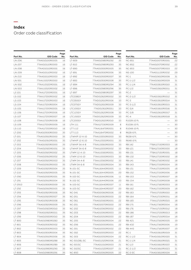
39
—Index Order code classification
I N D E X - O R D ER CO D E CL A SSIFI C ATI O N
Part No. GID CodePage
No.
LN-206 7TAA010100R0005 16
LN-207 7TAA010110R0000 16
LN-208 7TAA010110R0001 16
LN-209 7TAA010110R0002 16
LN-210 7TAA010110R0003 16
LN-501 7TAA115520R0000 16
LN-502 7TAA115520R0001 16
LN-503 7TAA115520R0002 16
LS 101 7TAA117200R0001 16
LS-102 7TAA117200R0002 16
LS-103 7TAA117200R0003 16
LS-104 7TAA117200R0004 16
LS-105 7TAA117200R0005 16
LS-106 7TAA117200R0006 16
LS-107 7TAA117200R0007 16
LS-108 7TAA117200R0008 16
LS-109 7TAA117200R0009 16
LS-110 7TAA117200R0010 16
LT-200 7TAA010930R0000 35
LT-201 7TAA010910R0000 35
LT-202 7TAA010910R0001 35
LT-203 7TAA010920R0000 35
LT-204 7TAA010920R0001 35
LT-205 7TAA010920R0002 35
LT-206 7TAA010910R0002 35
LT-207 7TAA010920R0003 35
LT-208 7TAA010910R0003 35
LT-209 7TAA010920R0004 35
LT-210 7TAA010920R0005 35
LT-290 7TAA010930R0001 35
LT-291 7TAA010910R0004 35
LT-2910 7TAA010930R0009 35
LT-292 7TAA010910R0005 35
LT-293 7TAA010920R0006 35
LT-294 7TAA010920R0007 35
LT-295 7TAA010920R0008 35
LT-296 7TAA010920R0009 35
LT-297 7TAA010920R0010 35
LT-298 7TAA010920R0011 35
LT-299 7TAA010930R0010 35
LT-800 7TAA010980R0283 35
LT-801 7TAA010930R0002 35
LT-802 7TAA010930R0003 35
LT-803 7TAA010930R0004 35
LT-804 7TAA010910R0006 35
LT-805 7TAA010980R0288 35
LT-806 7TAA010980R0289 35
LT-807 7TAA010980R0290 35
LT-808 7TAA010980R0291 35
Part No. GID CodePage
No.
LT-809 7TAA010980R0292 35
LT-810 7TAA010980R0293 35
LT-890 7TAA010930R0005 35
LT-891 7TAA010930R0006 35
LT-892 7TAA010930R0007 35
LT-893 7TAA010930R0008 35
LT-894 7TAA010980R0294 35
LT-896 7TAA010980R0296 35
LT-897 7TAA010980R0297 35
LTC038GY 7TAD012620R0002 33
LTC050GY 7TAD012610R0006 33
LTC075GY 7TAD012610R0009 33
LTC100GY 7TAD012610R0011 33
LTC125GY 7TAD012620R0008 33
LTC150GY 7TAD012620R0009 33
LTC200GY 7TAD012620R0010 33
LTH 111 7TAA117330R0009 8
LTT-112 7TAA116470R0001 8
LTT-113 7TAA116470R0002 8
LTWHIP 12-4-10 7TAA115550R0000 33
LTWHIP 12-6-10 7TAA115550R0001 33
LTWHIP 34-4-8 7TAA115560R0000 33
LTWHIP 34-6-8 7TAA115550R0002 33
LTWM 12-4-10 7TAA115560R0001 33
LTWM 12-6-10 7TAA115550R0003 33
LTWM 34-4-8 7TAA115560R0002 33
LTWM 34-6-8 7TAA115550R0004 33
N-101-SC 7TAA116440R0005 11
N-101-SC 7TAA116440R0005 20
N-102-SC 7TAA116440R0006 11
N-102-SC 7TAA116440R0006 20
N-103-SC 7TAA116440R0007 11
N-103-SC 7TAA116440R0007 20
NC-041 7TAA010060R0006 22
NC-051 7TAA010060R0000 22
NC-061 7TAA010060R0001 22
NC-201 7TAA010070R0000 22
NC-202 7TAA010060R0002 22
NC-203 7TAA010060R0003 22
NC-204 7TAA010050R0000 22
NC-205 7TAA010060R0004 22
NC-206 7TAA010050R0001 22
NC-301 7TAA010050R0002 22
NC-302 7TAA010050R0003 22
NC-303 7TAA010050R0004 22
NC-501DBL-SC 7TAA011520R0006 21
NC-501SC 7TAA011510R0003 21
NC-502SC 7TAA011520R0007 21
NC-850 7TAA010060R0005 22
Part No. GID CodePage
No.
NC-851 7TAA010070R0001 22
NC-852 7TAA010070R0002 22
NC-853 7TAA010070R0003 22
NS-100 7TAA011130R0032 29
PC-1 7TAA015610R0008 31
PC-1-1/2 7TAA015610R0009 31
PC-1-1/4 7TAA015610R0010 31
PC-1/2 7TAA015610R0011 31
PC-2 — 31
PC-2-1/2 7TAA015610R0012 31
PC-3 7TAA015610R0014 31
PC-3-1/2 7TAA015610R0015 31
PC-3/4 7TAA015610R0016 31
PC-3/8 7TAA015610R0017 31
PC-4 7TAA015610R0018 31
R1028-10 ft. — 30
R1038-10 ft. — 30
R1048-10 ft. — 30
R628-6 ft. — 30
R638-6 ft. — 30
R648-6 ft. — 30
RB 142 7TBA117150R0003 18
RB-121 7TBA117150R0000 18
RB-131 7TBA117150R0001 18
RB-132 7TBA117150R0002 18
RB-141 7TBA117160R0002 18
RB-143 7TBA117150R0004 18
RB-151 7TAA117150R0005 18
RB-152 7TAA117150R0006 18
RB-153 7TAA117150R0007 18
RB-154 7TAA117150R0008 18
RB-161 7TAA117160R0003 18
RB-162 7TAA117150R0009 18
RB-163 7TAA117150R0010 18
RB-164 7TAA117150R0011 18
RB-165 7TAA117150R0015 18
RB-175 7TAA117160R0004 18
RB-176 7TAA117150R0012 18
RB-186 7TAA117150R0013 18
RB-187 7TAA117150R0014 18
RB-421 7TAA117160R0005 19
RB-432 7TAA117160R0006 19
RB-443 7TAA117160R0007 19
RC-1 7TAA015610R0019 31
RC-1-1/2 7TAA015610R0020 31
RC-1-1/4 7TAA015610R0021 31
RC-1/2 7TAA015610R0022 31
RC-2-1/2 7TAA015610R0023 31
RC-2-SC 7TAA015610R0024 31
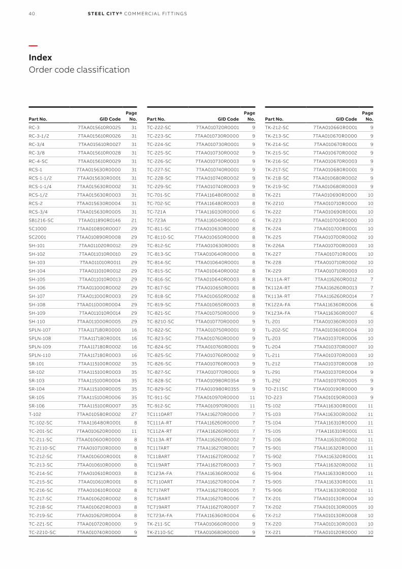
40 S TE E L CIT Y® CO M M ER CI A L FIT TI N G S
—Index Order code classification
Part No. GID CodePage
No.
RC-3 7TAA015610R0025 31
RC-3-1/2 7TAA015610R0026 31
RC-3/4 7TAA015610R0027 31
RC-3/8 7TAA015610R0028 31
RC-4-SC 7TAA015610R0029 31
RCS-1 7TAA015630R0000 31
RCS-1-1/2 7TAA015630R0001 31
RCS-1-1/4 7TAA015630R0002 31
RCS-1/2 7TAA015630R0003 31
RCS-2 7TAA015630R0004 31
RCS-3/4 7TAA015630R0005 31
SB1216-SC 7TAA011890R0146 21
SC1000 7TAA010890R0007 29
SC2001 7TAA010890R0008 29
SH-101 7TAA011020R0012 29
SH-102 7TAA011010R0010 29
SH-103 7TAA011010R0011 29
SH-104 7TAA011010R0012 29
SH-105 7TAA011010R0013 29
SH-106 7TAA011000R0002 29
SH-107 7TAA011000R0003 29
SH-108 7TAA011000R0004 29
SH-109 7TAA011010R0014 29
SH-110 7TAA011000R0005 29
SPLN-107 7TAA117180R0000 16
SPLN-108 7TAA117180R0001 16
SPLN-109 7TAA117180R0002 16
SPLN-110 7TAA117180R0003 16
SR-101 7TAA115100R0002 35
SR-102 7TAA115100R0003 35
SR-103 7TAA115100R0004 35
SR-104 7TAA115100R0005 35
SR-105 7TAA115100R0006 35
SR-106 7TAA115100R0007 35
T-102 7TAA010580R0002 27
TC-102-SC 7TAA116480R0001 8
TC-201-SC 7TAA010620R0000 11
TC-211-SC 7TAA010600R0000 8
TC-2110-SC 7TAA010710R0000 8
TC-212-SC 7TAA010600R0001 8
TC-213-SC 7TAA010610R0000 8
TC-214-SC 7TAA010610R0003 8
TC-215-SC 7TAA010610R0001 8
TC-216-SC 7TAA010610R0002 8
TC-217-SC 7TAA010620R0002 8
TC-218-SC 7TAA010620R0003 8
TC-219-SC 7TAA010620R0004 8
TC-221-SC 7TAA010720R0000 9
TC-2210-SC 7TAA010740R0000 9
Part No. GID CodePage
No.
TC-222-SC 7TAA010720R0001 9
TC-223-SC 7TAA010730R0000 9
TC-224-SC 7TAA010730R0001 9
TC-225-SC 7TAA010730R0002 9
TC-226-SC 7TAA010730R0003 9
TC-227-SC 7TAA010740R0001 9
TC-228-SC 7TAA010740R0002 9
TC-229-SC 7TAA010740R0003 9
TC-701-SC 7TAA116480R0002 8
TC-702-SC 7TAA116480R0003 8
TC-721A 7TAA116030R0000 6
TC-723A 7TAA116040R0000 6
TC-811-SC 7TAA010630R0000 8
TC-8110-SC 7TAA010650R0000 8
TC-812-SC 7TAA010630R0001 8
TC-813-SC 7TAA010640R0000 8
TC-814-SC 7TAA010640R0001 8
TC-815-SC 7TAA010640R0002 8
TC-816-SC 7TAA010640R0003 8
TC-817-SC 7TAA010650R0001 8
TC-818-SC 7TAA010650R0002 8
TC-819-SC 7TAA010650R0003 8
TC-821-SC 7TAA010750R0000 9
TC-8210-SC 7TAA010770R0000 9
TC-822-SC 7TAA010750R0001 9
TC-823-SC 7TAA010760R0000 9
TC-824-SC 7TAA010760R0001 9
TC-825-SC 7TAA010760R0002 9
TC-826-SC 7TAA010760R0003 9
TC-827-SC 7TAA010770R0001 9
TC-828-SC 7TAA010980R0354 9
TC-829-SC 7TAA010980R0355 9
TC-911-SC 7TAA010970R0000 11
TC-912-SC 7TAA010970R0001 11
TC1110ART 7TAA116270R0000 7
TC111A-RT 7TAA116260R0000 7
TC112A-RT 7TAA116260R0001 7
TC113A-RT 7TAA116260R0002 7
TC117ART 7TAA116270R0001 7
TC118ART 7TAA116270R0002 7
TC119ART 7TAA116270R0003 7
TC123A-FA 7TAA116360R0002 6
TC7110ART 7TAA116270R0004 7
TC717ART 7TAA116270R0005 7
TC718ART 7TAA116270R0006 7
TC719ART 7TAA116270R0007 7
TC723A-FA 7TAA116360R0004 6
TK-211-SC 7TAA010660R0000 9
TK-2110-SC 7TAA010680R0000 9
Part No. GID CodePage
No.
TK-212-SC 7TAA010660R0001 9
TK-213-SC 7TAA010670R0000 9
TK-214-SC 7TAA010670R0001 9
TK-215-SC 7TAA010670R0002 9
TK-216-SC 7TAA010670R0003 9
TK-217-SC 7TAA010680R0001 9
TK-218-SC 7TAA010680R0002 9
TK-219-SC 7TAA010680R0003 9
TK-221 7TAA010690R0000 10
TK-2210 7TAA010710R0000 10
TK-222 7TAA010690R0001 10
TK-223 7TAA010700R0000 10
TK-224 7TAA010700R0001 10
TK-225 7TAA010700R0002 10
TK-226A 7TAA010700R0003 10
TK-227 7TAA010710R0001 10
TK-228 7TAA010710R0002 10
TK-229 7TAA010710R0003 10
TK111A-RT 7TAA116260R0012 7
TK112A-RT 7TAA116260R0013 7
TK113A-RT 7TAA116260R0014 7
TK122A-FA 7TAA116360R0006 6
TK123A-FA 7TAA116360R0007 6
TL-201 7TAA010360R0003 10
TL-202-SC 7TAA010360R0004 10
TL-203 7TAA010370R0006 10
TL-204 7TAA010370R0007 10
TL-211 7TAA010370R0003 10
TL-212 7TAA010370R0008 10
TL-291 7TAA010370R0004 9
TL-292 7TAA010370R0005 9
TO-211SC 7TAA010190R0000 9
TO-223 7TAA010190R0003 9
TS-102 7TAA116300R0001 11
TS-103 7TAA116300R0002 11
TS-104 7TAA116310R0000 11
TS-105 7TAA116310R0001 11
TS-106 7TAA116310R0002 11
TS-901 7TAA116320R0000 11
TS-902 7TAA116320R0001 11
TS-903 7TAA116320R0002 11
TS-904 7TAA116330R0000 11
TS-905 7TAA116330R0001 11
TS-906 7TAA116330R0002 11
TX-201 7TAA010130R0004 10
TX-202 7TAA010130R0005 10
TX-212 7TAA010130R0008 10
TX-220 7TAA010130R0003 10
TX-221 7TAA010120R0000 10
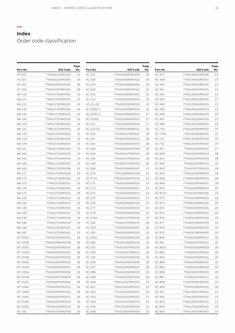
41
—Index Order code classification
Part No. GID CodePage
No.
TX-222 7TAA010120R0001 10
TX-223 7TAA010120R0002 10
UF-201 7TAA010870R0000 28
UF-202 7TAA010870R0001 28
WA-110 7TAA117310R0000 19
WA-121 7TBA117300R0000 19
WA-131 7TBA117300R0001 19
WA-132 7TBA117300R0002 19
WA-141 7TBA117310R0001 19
WA-142 7TBA117300R0003 19
WA-143 7TBA117300R0004 19
WA-151 7TBA117310R0002 19
WA-152 7TBA117300R0005 19
WA-153 7TBA117300R0006 19
WA-154 7TBA117310R0003 19
WA-161 7TBA117310R0004 19
WA-162 7TBA117310R0005 19
WA-163 7TBA117310R0006 19
WA-164 7TBA117310R0007 19
WA-165 7TBA117310R0008 19
WA-171 7TAA117310R0009 19
WA-172 7TAA117310R0010 19
WA-173 7TAA117310R0011 19
WA-174 7TAA117310R0012 19
WA-175 7TAA117310R0013 19
WA-176 7TAA117310R0014 19
WA-181 7TAA117310R0015 19
WA-182 7TAA117310R0016 19
WA-183 7TAA117310R0017 19
WA-184 7TAA117310R0018 19
WA-185 7TAA117310R0019 19
WA-186 7TAA117300R0007 19
WA-187 7TAA117310R0020 19
WT-203A 7TAA010870R0002 28
WT-203B 7TAA010980R0408 28
WT-203C 7TAA010870R0003 28
WT-204A 7TAA010870R0004 28
WT-204B 7TAA010870R0005 28
WT-204C 7TAA010870R0006 28
WT-204D 7TAA010870R0007 28
WT-205A 7TAA010870R0008 28
WT-205B 7TAA010870R0009 28
WT-205C 7TAA010870R0010 28
WT-206A 7TAA010870R0011 28
WT-206B 7TAA010870R0012 28
WT-206C 7TAA010870R0013 28
WT-206D 7TAA010870R0014 28
WT-206E 7TAA010870R0015 28
XC-130 7TAA011070R0056 25
Part No. GID CodePage
No.
XC-201 7TAA010580R0009 24
XC-202 7TAA010580R0022 24
XC-203 7TAA010980R0416 24
XC-204 7TAA010980R0412 24
XC-210 7TAA010550R0000 22
XC-210 7TAA010550R0000 26
XC-211-SC 7TAA010580R0010 22
XC-2200-C 7TAA010560R0003 22
XC-2200-C 7TAA010560R0003 27
XC-220SC 7TAA010560R0002 27
XC-221 7TAA010560R0004 27
XC-222-SC 7TAA010580R0011 22
XC-240 7TAA010570R0002 28
XC-241 7TAA010560R0022 28
XC-242 7TAA010560R0005 28
XC-243 7TAA010560R0006 28
XC-244 7TAA010570R0003 28
XC-245 7TAA010570R0004 28
XC-246 7TAA010570R0005 28
XC-269 7TAA010560R0007 23
XC-270 7TAA010560R0008 23
XC-2710 7TAA010560R0009 23
XC-272 7TAA010560R0010 23
XC-273 7TAA010560R0011 23
XC-274 7TAA010560R0012 23
XC-275 7TAA010560R0013 23
XC-276 7TAA010560R0014 23
XC-277 7TAA010560R0015 23
XC-278 7TAA010560R0016 23
XC-278A 7TAA010570R0006 23
XC-280 7TAA010550R0001 26
XC-290 7TAA010560R0017 26
XC-291 7TAA010560R0023 26
XC-2910 7TAA010560R0024 26
XC-292 7TAA010560R0018 26
XC-293 7TAA010570R0007 26
XC-294 7TAA010570R0014 26
XC-295 7TAA010560R0019 26
XC-296 7TAA010560R0025 26
XC-297 7TAA010560R0020 26
XC-298 7TAA010560R0026 26
XC-299 7TAA010570R0008 26
XC-400 7TAA135020R0000 23
XC-401 7TAA135010R0000 23
XC-402 7TAA135020R0001 23
XC-403 7TAA135020R0002 23
XC-404 7TAA135020R0003 23
XC-405 7TAA135020R0004 23
XC-406 7TAA135020R0005 23
Part No. GID CodePage
No.
XC-407 7TAA135020R0006 23
XC-408 7TAA135020R0007 23
XC-490 7TAA135030R0000 23
XC-491 7TAA135030R0001 23
XC-492 7TAA135030R0002 23
XC-493 7TAA135040R0000 23
XC-494 7TAA135040R0001 23
XC-495 7TAA135030R0003 23
XC-496 7TAA135030R0004 23
XC-497 7TAA135030R0005 23
XC-498 7TAA135030R0006 23
XC-730 7TAA135080R0000 25
XC-7300 7TAA135080R0001 25
XC-731 7TAA135080R0002 25
XC-732 7TAA135090R0000 25
XC-821 7TAA010580R0012 27
XC-840 7TAA010580R0013 28
XC-841 7TAA010570R0009 28
XC-842 7TAA010570R0010 28
XC-843 7TAA010570R0015 28
XC-844 7TAA010580R0024 28
XC-845 7TAA010580R0025 28
XC-846 7TAA010980R0427 28
XC-870 7TAA010580R0014 24
XC-8710 7TAA010570R0016 24
XC-872 7TAA010580R0015 24
XC-873 7TAA010580R0016 24
XC-874 7TAA010580R0026 24
XC-875 7TAA010580R0027 24
XC-876 7TAA010580R0028 24
XC-877 7TAA010580R0029 24
XC-878 7TAA010580R0030 24
XC-879 7TAA010980R0428 24
XC-890 7TAA010580R0017 26
XC-891 7TAA010570R0011 26
XC-8910 7TAA010580R0018 26
XC-892 7TAA010570R0012 26
XC-893 7TAA010560R0021 26
XC-894 7TAA010580R0031 26
XC-895 7TAA010580R0019 26
XC-896 7TAA010570R0018 26
XC-897 7TAA010570R0013 26
XC-898 7TAA010580R0020 26
XC-899 7TAA010580R0021 26
XC-901 7TAA135050R0000 23
XC-902 7TAA135050R0001 23
XC-903 7TAA135060R0000 23
XC-904 7TAA135060R0001 23
XC-905 7TAA135070R0000 23
I N D E X - O R D ER CO D E CL A SSIFI C ATI O N
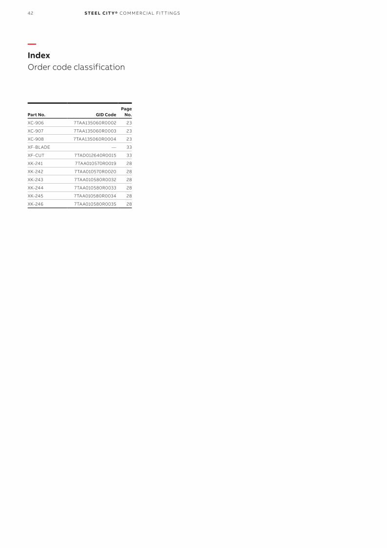
42 S TE E L CIT Y® CO M M ER CI A L FIT TI N G S
—Index Order code classification
Part No. GID CodePage
No.
XC-906 7TAA135060R0002 23
XC-907 7TAA135060R0003 23
XC-908 7TAA135060R0004 23
XF-BLADE — 33
XF-CUT 7TAD012640R0015 33
XK-241 7TAA010570R0019 28
XK-242 7TAA010570R0020 28
XK-243 7TAA010580R0032 28
XK-244 7TAA010580R0033 28
XK-245 7TAA010580R0034 28
XK-246 7TAA010580R0035 28

43
—Notes
N OTE S

44 S TE E L CIT Y® CO M M ER CI A L FIT TI N G S
—Notes

45
—Notes
N OTE S

46 S TE E L CIT Y® CO M M ER CI A L FIT TI N G S
Additional informationWe reserve the right to make technical changes or modify the contents of this document without prior notice. With regard to purchase orders, the agreed particulars shall prevail. ABB AG does not accept any responsibility whatsoever for potential errors or possible lack of information in this document.
We reserve all rights in this document and in the subject matter and illustrations contained therein. Any reproduction, disclosure to third parties or utilisation of its contents – in whole or in parts – is forbidden without prior written consent of ABB AG.

47

© Copyright 2018 ABB. All rights reserved. Specifications subject to change without notice. 7T
KK
00
012
1 R
EV
A 2
1.0
9.2
018
—USABB Installation Products Electrification Products division 860 Ridge Lake Blvd. Memphis, TN 38120+1 901-252-5000
tnb.abb.com