Embed Size (px)
Citation preview
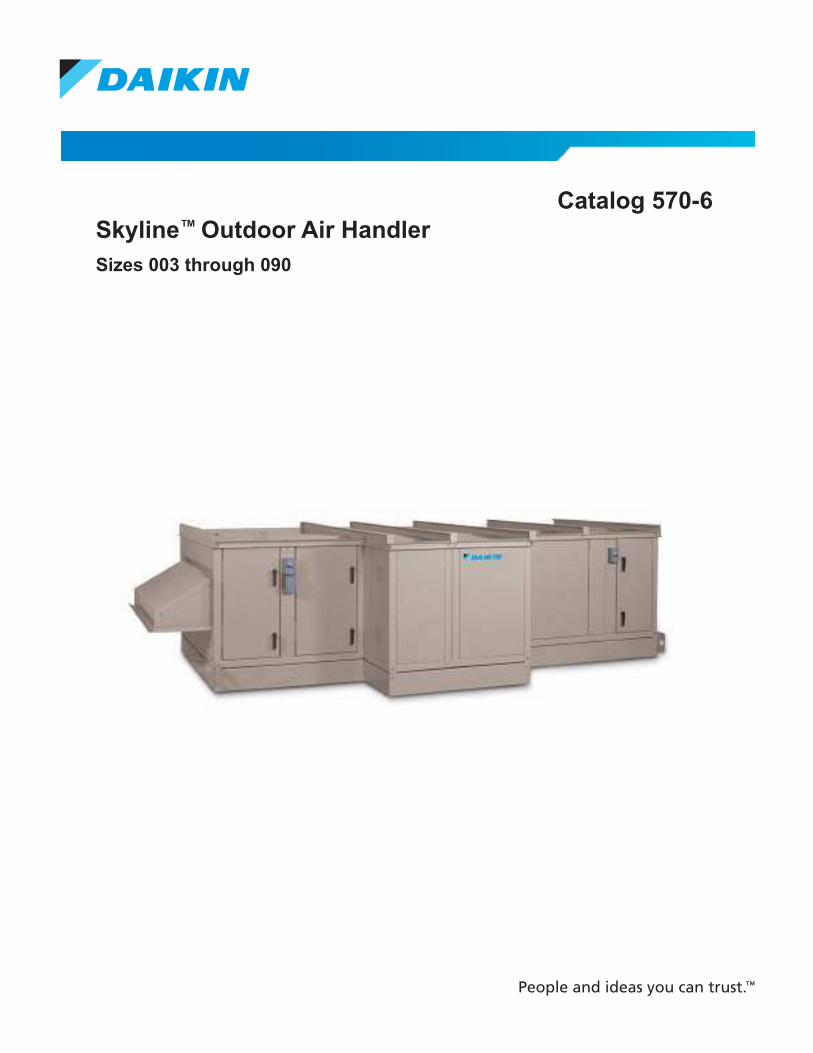
Catalog 570-6
Skyline™ Outdoor Air Handler
Sizes 003 through 090
Table of ConTenTs
Table of ConTenTs
Nomenclature and Certiication . . . . . . . . . . . . . . . . . 3
AHRI Certiication . . . . . . . . . . . . . . . . . . . . . . . . 3
IBC Certiication (optional) . . . . . . . . . . . . . . . . . . . . . 3
Agency Listed . . . . . . . . . . . . . . . . . . . . . . . . . . . . 3
The Skyline Air Handler Advantage . . . . . . . . . . . . . . 4
Introduction . . . . . . . . . . . . . . . . . . . . . . . . . . . . . . . . . 6
Quality . . . . . . . . . . . . . . . . . . . . . . . . . . . . . . . . . . . . 6
Flexibility . . . . . . . . . . . . . . . . . . . . . . . . . . . . . . . . . . 6
Cabinet Construction . . . . . . . . . . . . . . . . . . . . . . . . . 6
Access and Serviceability . . . . . . . . . . . . . . . . . . . . . 8
Seismic Design Considerations . . . . . . . . . . . . . . . . . 9
Daikin SelectTools™ Software Selection Program . . . 9
Skyline’s Unique Standard Features . . . . . . . . . . . . 10
Skyline Customized Options . . . . . . . . . . . . . . . . . . 12
Component Types . . . . . . . . . . . . . . . . . . . . . . . . . . . 14
Fans . . . . . . . . . . . . . . . . . . . . . . . . . . . . . . . . . . . . . 14
Coils . . . . . . . . . . . . . . . . . . . . . . . . . . . . . . . . . . . . . 16
Filters . . . . . . . . . . . . . . . . . . . . . . . . . . . . . . . . . . . . 17
Access . . . . . . . . . . . . . . . . . . . . . . . . . . . . . . . . . . . 19
Mixing Boxes and Economizers . . . . . . . . . . . . . . . . 19
Face and Bypass Dampers . . . . . . . . . . . . . . . . . . . 19
Blenders/Air Mixers . . . . . . . . . . . . . . . . . . . . . . . . . 20
Attenuators . . . . . . . . . . . . . . . . . . . . . . . . . . . . . . . . 20
Air Handler Selection . . . . . . . . . . . . . . . . . . . . . . . . 21
Selecting Coils . . . . . . . . . . . . . . . . . . . . . . . . . . . . . 21
Selecting Accessories . . . . . . . . . . . . . . . . . . . . . . . 21
Selecting Fans . . . . . . . . . . . . . . . . . . . . . . . . . . . . . 21
Quick Select Tables . . . . . . . . . . . . . . . . . . . . . . . . . . 22
Application Considerations . . . . . . . . . . . . . . . . . . . 24
Installation Flexibility . . . . . . . . . . . . . . . . . . . . . . . . 24
Unit Location . . . . . . . . . . . . . . . . . . . . . . . . . . . . . . 24
Curb Installation . . . . . . . . . . . . . . . . . . . . . . . . . . . . 24
Ductwork . . . . . . . . . . . . . . . . . . . . . . . . . . . . . . . . . 24
Piping and Drain Pan Traps . . . . . . . . . . . . . . . . . . . 25
Coil Freeze Protection . . . . . . . . . . . . . . . . . . . . . . . 25
Vibration Isolation . . . . . . . . . . . . . . . . . . . . . . . . . . . 25
Sound . . . . . . . . . . . . . . . . . . . . . . . . . . . . . . . . . . . . 25
Filters . . . . . . . . . . . . . . . . . . . . . . . . . . . . . . . . . . . . 25
Air Supply Systems and Fan Laws . . . . . . . . . . . . . 26
Fan and Motor Heat . . . . . . . . . . . . . . . . . . . . . . . . . 27
Variable Air Volume . . . . . . . . . . . . . . . . . . . . . . . . . 27
Engineering and Physical Data . . . . . . . . . . . . . . . . 28
Component and Section Weights . . . . . . . . . . . . . . . 40
Fan Data . . . . . . . . . . . . . . . . . . . . . . . . . . . . . . . . . 42
Coil Data . . . . . . . . . . . . . . . . . . . . . . . . . . . . . . . . . 44
Side Load Filter Data . . . . . . . . . . . . . . . . . . . . . . . . 46
Dimensional Data . . . . . . . . . . . . . . . . . . . . . . . . . . . 48
Electrical Data . . . . . . . . . . . . . . . . . . . . . . . . . . . . . . 77
Supply Power Wiring . . . . . . . . . . . . . . . . . . . . . . . . 77
Engineering Guide Speciication . . . . . . . . . . . . . . . 78
CAT 570-6 • SKYLINE OUTDOOR AIR HANDLER 2 www.DaikinApplied.com
Table of ConTenTs
nomenClaTure and CerTifiCaTion
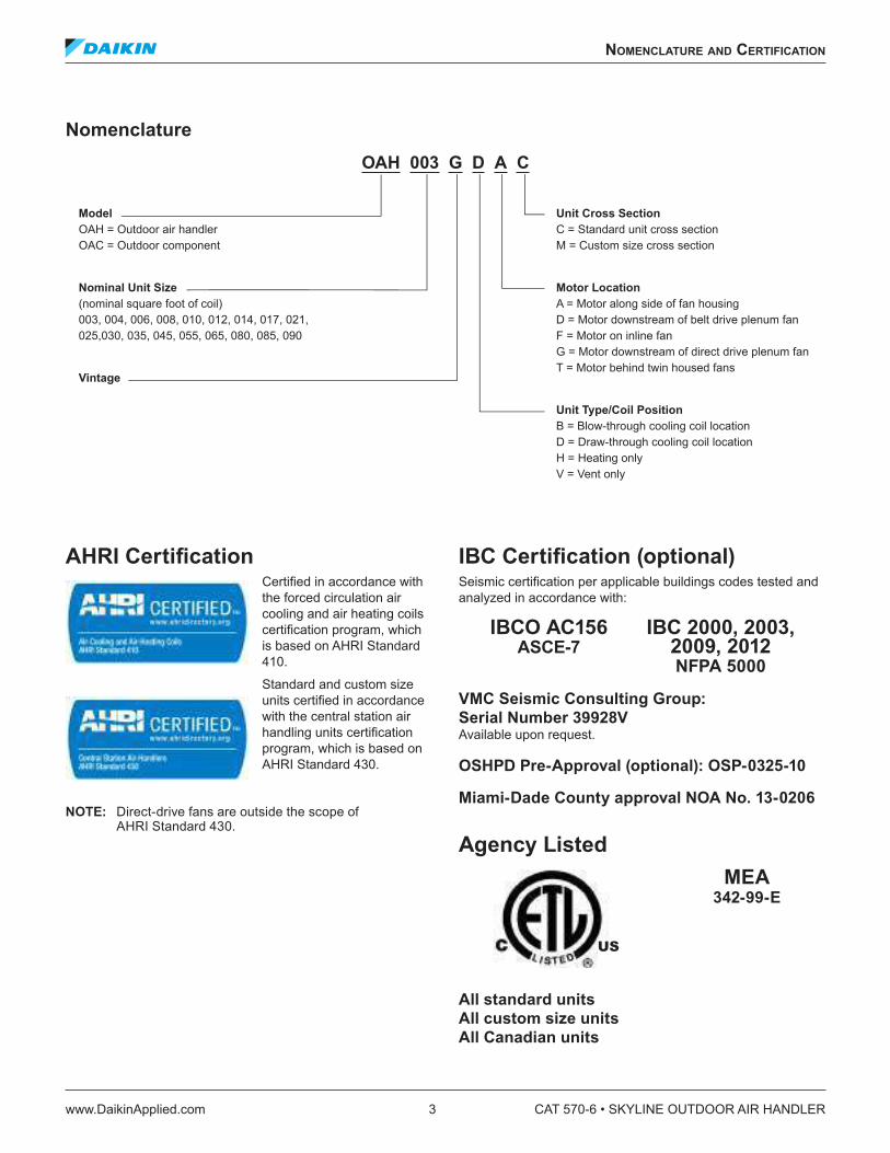
Nomenclature
AHRI Certiication Certiied in accordance with the forced circulation air cooling and air heating coils certiication program, which is based on AHRI Standard 410.
Standard and custom size units certiied in accordance with the central station air handling units certiication program, which is based on AHRI Standard 430.
NOTE: Direct-drive fans are outside the scope of AHRI Standard 430.
IBC Certiication (optional) Seismic certiication per applicable buildings codes tested and analyzed in accordance with:
IBCO AC156 IBC 2000, 2003, ASCE-7 2009, 2012 NFPA 5000
VMC Seismic Consulting Group:
Serial Number 39928V Available upon request.
OSHPD Pre-Approval (optional): OSP-0325-10
Miami-Dade County approval NOA No. 13-0206
Agency Listed
MEA 342-99-E
All standard units
All custom size units
All Canadian units
OAH 003 G D A C
Model
OAH = Outdoor air handler OAC = Outdoor component
Nominal Unit Size
(nominal square foot of coil) 003, 004, 006, 008, 010, 012, 014, 017, 021, 025,030, 035, 045, 055, 065, 080, 085, 090
Vintage
Unit Cross Section
C = Standard unit cross section M = Custom size cross section
Motor Location
A = Motor along side of fan housing D = Motor downstream of belt drive plenum fan F = Motor on inline fan G = Motor downstream of direct drive plenum fan T = Motor behind twin housed fans
Unit Type/Coil Position
B = Blow-through cooling coil location D = Draw-through cooling coil location H = Heating only V = Vent only
US
nomenClaTure and CerTifiCaTion
www.DaikinApplied.com 3 CAT 570-6 • SKYLINE OUTDOOR AIR HANDLER
The skyline air handler advanTage
Flexibility Skyline’s unique design What it can do for you
Custom-modular platform Allows customizing of the system with a wide selection of components and sizes.
Variable Dimensioning™ design Allows cabinet to be sized in two-inch increments (height and width) to meet installation or aesthetic requirements.
Multiple coil face areas per model size Allows you to closely match performance and capacity requirements.
Multiple customized component options for fans, coils, ilters and cabinet construction
Allows optimum selections for cost, energy eficiency, performance, indoor air quality, and low noise.
Optional factory-supplied roof curb with separate pipe chase in variable heights (16", 20", 24" or 30")
Designed speciically for your unit and your height requirements.
Indoor Air QualitySkyline’s unique design What it can do for you
Low-leakage cabinet constructionStandard Cabinet: less than 0.5 CFM/ft2 of cabinetry at -6" to +5" positive w.c.Custom Air Handler Cabinet: less than Class 6 leakage up to +/- 8" w.c.
Minimizes air leakage, noise and uniltered air.
Double sloped microbial-resistant coated galvanized (standard) or stainless steel drain pan
Inhibits bacterial growth; eliminates standing water that can support bacteria.
Double-wall, foam injected construction Smooth interior surfaces reduce potential for accumulating dirt and mircrobial growth. Eliminates iberglass ibers eroding into the air stream.
Multiple ilter types (lat, angular, bag and cartridge) with side-load and front-load capabilities
Gives full range of ilter eficiencies, inal ilter arrangements, and ilter section depth lexibility.
Hinged access doors with full-grip handles or easy-to-remove access panels
Allows for easy inspection and cleaning of drain pans; promotes regular inspections.
Patented gasketed frame channels Minimizes direct exposure of metal to metal in cabinet framework to reduce cold bridging and condensate collection; lowers operating costs.
Patented splice collar Prevents uniltered, unconditioned air from entering the system. Allows for leak-resistant section to section joining in the ield.
CAT 570-6 • SKYLINE OUTDOOR AIR HANDLER 4 www.DaikinApplied.com
The skyline air handler advanTage
Operating EficiencySkyline’s unique design What it can do for you
Low air-leakage cabinet design, all inside and outside panel penetrations are sealed
Increases operating eficiency; reduces energy loss and operating costs.
Patented gasketed frame channels Minimizes direct exposure of metal to metal in cabinet framework to reduce cold bridging and condensate collection; lowers operating costs.
Fan selection options (housed forward curve or airfoil, belt drive or direct drive plenum, inline and twin fans, fan array)
Results in lowest possible BHP requirements.
Patented UltraSeal™ low-leak dampers Maximizes operating eficiency; reduces operating cost.
Easy, Low Cost InstallationSkyline’s unique design What it can do for you
Ships assembled or in sections (if required) with optional heavy duty base rail and lifting lugs on all four corners
Facilitates easy rigging and installation.
Patented section splicing (if required) Saves installation time; creates an airtight environment.Optional factory supplied roof curb with separate pipe chase in variable heights (16", 20", 24" or 30")
Designed to match custom modular lexibility of your unit and your height requirements.
Variable depth piping vestibules Allows you to select vestibule depth to match piping requirements.
Coil connections extend through cabinet with gasketed airseal, external drains and vents
Allows easy connection in piping vestibule to save time and cost; preserves air-tight environment.
Fan system factory tested and balanced Saves time during installation and promotes proper operation.
Easy Maintenance and ServiceabilitySkyline’s unique design What it can do for you
Direct-drive plenum fans No fan bearings, belts or drives to replace or maintainExtended fan bearing lube lines Makes lubricating fan system easier.Extended coil drain connections Reduces coil venting time; helps coil condensate drain
completely.Hinged access doors with full grip handles or easy-to-remove access panels in a wide range of section depths
Makes it fast and easy to clean and inspect drain pan, clean or remove coil, clean interior.
Durable, Weathertight Cabinet for Long LifeSkyline’s Unique Design What It Does For You
Cross-broken roofcap and “C” cap over seam joints Eliminates standing water and provides a weathertight seal.Drip shield on all sides and over doors Directs water away from cabinet.Pre-painted cabinetry (galvanized optional) Resists corrosion for long life.Intake and exhaust hoods Direct rain or snow away from required openings.Galvanized or stainless steel liners Helps extend insulation life and allows easy cleaning.
The skyline air handler advanTage
www.DaikinApplied.com 5 CAT 570-6 • SKYLINE OUTDOOR AIR HANDLER
inTroduCTion
Quality Daikin Applied air handling equipment has been respected and regarded as high quality for nearly 60 years. Daikin Applied has taken a major step in redeining the outdoor air handler with the Skyline air handler. Demands for improved indoor air quality, low sound, and high operating eficiency require a better product for today’s air handler market. The Daikin Applied Skyline air handler is designed to meet or exceed these demands.
In addition to our patented construction, Daikin Applied Skyline outdoor air handlers feature a durable, weathertight cabinet that promotes long life of your air handler. Units ship completely assembled or by section (if necessary) with a curb-ready base rail and heavy-duty lifting lugs on all four corners to facilitate easy rigging and installation. An optional factory-supplied roof curb, speciically designed for your unit, is available in variable heights (from 16" to 30") to further simplify installation.
Flexibility By virtue of its unique frame design, the Daikin Applied Skyline outdoor air handler offers tremendous lexibility. This lexibility is relected in our unique Variable Dimensioning™ feature that allows units to be sized in two-inch increments (height and width) to meet your requirements. Numerous section and component options, and the ability to arrange components in whatever arrangement is required, allow Skyline air handlers to be customized to the requirements of each job, without expensive modiications in the ield.
The Daikin Skyline unit can be equipped with a unitized, single piece base. This allows for a single lift, greatly reducing the time a crane has to be on site. A time spent piecing individual section together is also minimized. This coniguration can be ordered with a factory manufactured, ield installed piping vestibule. This allows for wider units to be shipped on a standard lat-bed truck.
For those projects the need multiple lifts, the Daikin skyline unit can be broken into sections. This allows the lift to be completed with a smaller crane or to minimize the weight on a long boom crane. This coniguration comes equipped with a factory manufactured and installed piping vestibule.
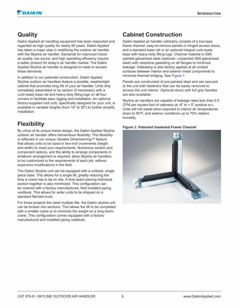
Cabinet Construction Daikin Applied air handler cabinetry consists of a box-type frame channel, easy-to-remove panels or hinged access doors, and a standard base rail or an optional integral curb-ready base with heavy-duty lifting lugs. Channel material is G90 painted galvanized steel (optional—unpainted G60 galvanized steel) with neoprene gasketing on all langes to minimize leakage. Gasketing is also factory applied at all contact surfaces between interior and exterior metal components to minimize thermal bridging. See Figure 1.
Panels are constructed of pre-painted steel and are secured to the unit with fasteners that can be easily removed to access the unit interior. Optional doors with full grip handles are also available.
Skyline air handlers are capable of leakage rates less than 0.5 CFM per square foot of cabinetry at -6" to + 5" positive w.c. Units will not sweat when exposed to interior air temperatures down to 50°F, and exterior conditions up to 70% relative humidity.
Figure 1: Patented Gasketed Frame Channel
CAT 570-6 • SKYLINE OUTDOOR AIR HANDLER 6 www.DaikinApplied.com
inTroduCTion
High Pressure Air Handler Cabinet
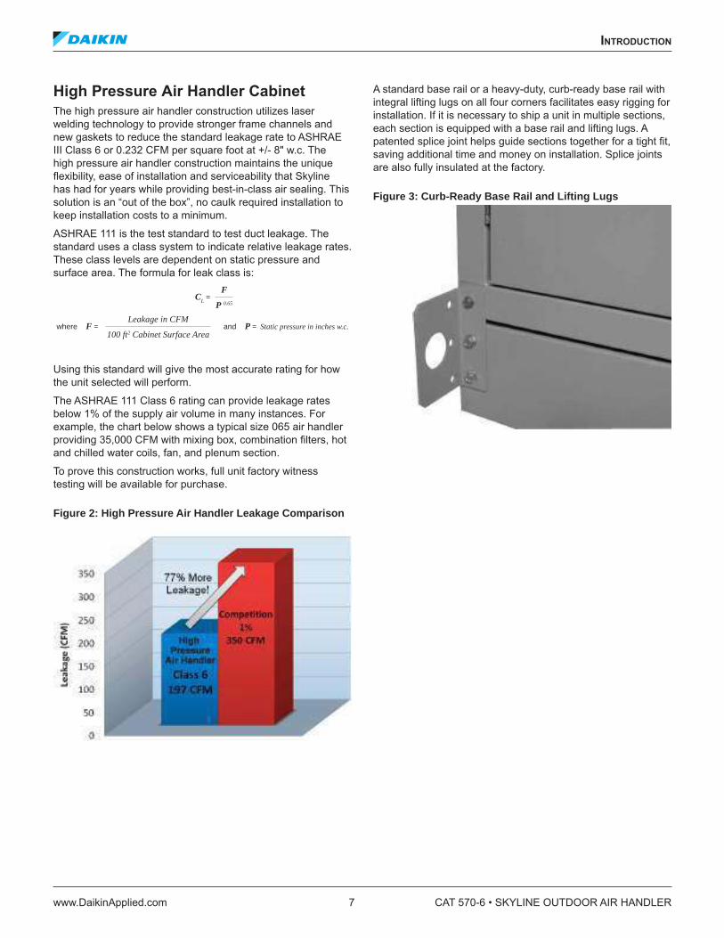
The high pressure air handler construction utilizes laser welding technology to provide stronger frame channels and new gaskets to reduce the standard leakage rate to ASHRAE III Class 6 or 0.232 CFM per square foot at +/- 8" w.c. The high pressure air handler construction maintains the unique lexibility, ease of installation and serviceability that Skyline has had for years while providing best-in-class air sealing. This solution is an “out of the box”, no caulk required installation to keep installation costs to a minimum.
ASHRAE 111 is the test standard to test duct leakage. The standard uses a class system to indicate relative leakage rates. These class levels are dependent on static pressure and surface area. The formula for leak class is:
Using this standard will give the most accurate rating for how the unit selected will perform.
The ASHRAE 111 Class 6 rating can provide leakage rates below 1% of the supply air volume in many instances. For example, the chart below shows a typical size 065 air handler providing 35,000 CFM with mixing box, combination ilters, hot and chilled water coils, fan, and plenum section.
To prove this construction works, full unit factory witness testing will be available for purchase.
Figure 2: High Pressure Air Handler Leakage Comparison
A standard base rail or a heavy-duty, curb-ready base rail with integral lifting lugs on all four corners facilitates easy rigging for installation. If it is necessary to ship a unit in multiple sections, each section is equipped with a base rail and lifting lugs. A patented splice joint helps guide sections together for a tight it, saving additional time and money on installation. Splice joints are also fully insulated at the factory.
Figure 3: Curb-Ready Base Rail and Lifting Lugs
and P = Static pressure in inches w.c.where F = Leakage in CFM
100 ft2 Cabinet Surface Area
CL =
F
P 0.65
inTroduCTion
www.DaikinApplied.com 7 CAT 570-6 • SKYLINE OUTDOOR AIR HANDLER

Skyline air handlers are equipped with several features to provide durability against harsh outdoor conditions. Cross-broken roofcaps eliminate standing water on the unit and a “C” cap over seam joints provides a watertight seal. The roof cap extends over optional piping vestibules without any seams. Drip shield on all sides and over doors, as well as intake and exhaust hoods with screens, direct water away from the unit and required openings. An insulated, double-walled piping vestibule encloses all piping and control valves within the unit cabinet and can be selected in varying depths to meet your piping requirements.
Figure 4: Integral Piping Vestibule
Access and Serviceability Equipment must be designed to perform eficiently and withstand the wear and tear of everyday use. It also must be designed to provide easy access to interior components for routine maintenance and service to maintain peak performance. The patented frame channels and easy-to-remove panels or hinged access doors of the Skyline outdoor air handler cabinet provide complete access to the unit interior and components.
Figure 5: Hinged Access Doors
CAT 570-6 • SKYLINE OUTDOOR AIR HANDLER 8 www.DaikinApplied.com
inTroduCTion
Seismic Design Considerations Strict design, testing, and certiication requirements for heating, ventilating, and air-conditioning equipment are clearly deined in the International Building Code, versions 2000 and 2003, for designated structures in earthquake-prone locations. The goals of these requirements are to maintain systems to protect the public from hazard and maintain essential public services immediately after an earthquake. With the widespread adoption of the IBC throughout the U.S., it is important to understand its requirements and their impact on your speciic building, and where you can turn for equipment to satisfy those requirements. Tested and certiied compliant with the seismic provisions of the IBC, Daikin Applied Skyline air handlers also comply with the construction requirements of NFPA 5000.
For use by the building oficial and design professional, the IBC has deined Seismic Use Group designations based on building use along with speciic criteria for determining the Seismic Design Category of the building and the applicability of seismic design criteria to the building’s mechanical equipment. Provide this information to your local Daikin Applied Sales Representative so the proper modiications can be made to the air handler and have a compliance label afixed to the product so all IBC requirements in this regard are complied with. For additional information, Daikin Applied has several published articles explaining in detail IBC seismic requirements. Go to www.DaikinApplied.com or contact your local Daikin Applied sales representative to obtain these articles.
Daikin also has construction pre-certiied for California's strict Ofice of Statewide Health Planning & Development (OSHPD) requirements. The OSHPD pre-approval shows that Daikin has already completed testing to allow engineers to specify, contractors to install, and owners to operate equipment that will still work after a seismic event.
Daikin SelectTools™ Software
Selection Program Because the Daikin Applied Skyline air handler is so lexible and has so many different component types, there virtually are an ininite number of possible unit arrangements. To help the customer easily deine their product requirements, Daikin Applied provides a user-friendly software selection program, called Daikin SelectTools. This program conigures and sizes both standard and custom units. Components can be selected in minutes.
This Windows® based program leads the user through the selection process by prompting for pertinent input data for all components required. Component sections are selected by placing them on a coniguration screen. Once the unit layout is deined, the options and accessories are identiied. The program gives immediate feedback regarding fan and coil selection, offering a choice of many different options based on the performance inputs. Once inal component selections have been made, the program provides all output needed for speciication and submittal purposes, including fan curves, coil performance psychometric charts, weights, dimensional drawings, and a unit speciication.
Daikin SelectTools is a comprehensive, eficient and user-friendly software selection program.
inTroduCTion
www.DaikinApplied.com 9 CAT 570-6 • SKYLINE OUTDOOR AIR HANDLER
skyline’s unique sTandard feaTures
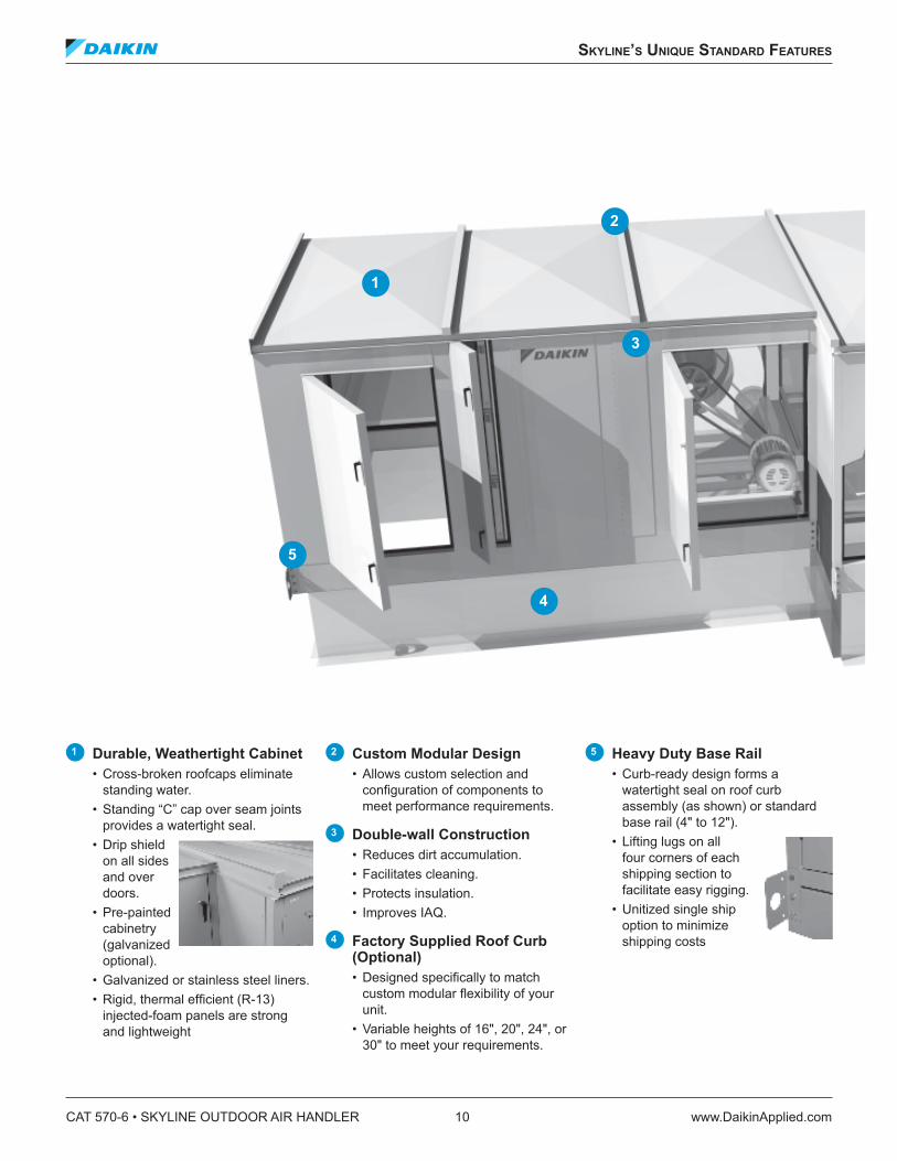
1 Durable, Weathertight Cabinet
• Cross-broken roofcaps eliminate standing water.
• Standing “C” cap over seam joints provides a watertight seal.
• Drip shield on all sides and over doors.
• Pre-painted cabinetry (galvanized optional).
• Galvanized or stainless steel liners. • Rigid, thermal eficient (R-13)
injected-foam panels are strong and lightweight
2 Custom Modular Design
• Allows custom selection and coniguration of components to meet performance requirements.
3 Double-wall Construction
• Reduces dirt accumulation. • Facilitates cleaning. • Protects insulation. • Improves IAQ.
4 Factory Supplied Roof Curb (Optional) • Designed speciically to match
custom modular lexibility of your unit.
• Variable heights of 16", 20", 24", or 30" to meet your requirements.
5 Heavy Duty Base Rail
• Curb-ready design forms a watertight seal on roof curb assembly (as shown) or standard base rail (4" to 12").
• Lifting lugs on all four corners of each shipping section to facilitate easy rigging.
• Unitized single ship option to minimize shipping costs
1
2
3
4
5
CAT 570-6 • SKYLINE OUTDOOR AIR HANDLER 10 www.DaikinApplied.com
skyline’s unique sTandard feaTures

6 Gasketed Frame Channel Construction
• Eliminates metal-to-metal contact between paneling and framework.
• Minimizes condensate and corrosion.
• Promotes long life.
7 Piping Vestibule (Optional) • Encloses piping connections within
unit cabinet. • Variable depths to meet your piping
requirements (18", 24", 30").
8 Patented Ultraseal™ Low-leak Dampers
• Maximize operating eficiency.
• Reduce operating costs.
9 Damper Hoods (Optional) with Screens • Direct rain, snow and debris away
from required openings.
10 Visible Double-sloped Drain Pan
• Microbial-resistant galvanized or optional stainless steel drain pan to inhibit bacteria growth.
• Makes inspection and cleaning easier.
• Improves IAQ.
11 Extended Coil and Drain Connections
• Saves installation costs. • Reduces maintenance time.
67 8
9
10
11
www.DaikinApplied.com 11 CAT 570-6 • SKYLINE OUTDOOR AIR HANDLER
skyline’s unique sTandard feaTures
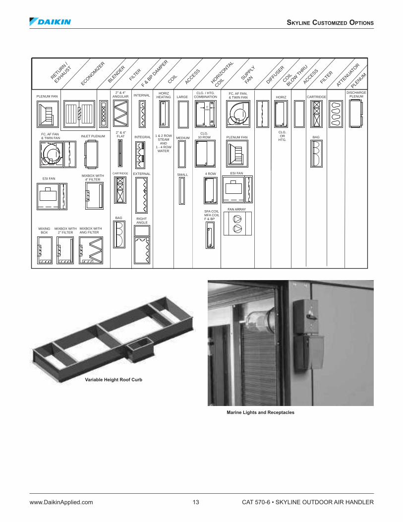
skyline CusTomized opTions
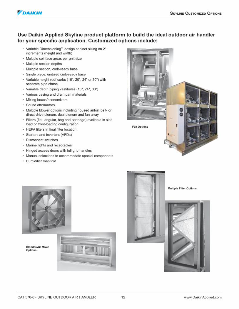
Use Daikin Applied Skyline product platform to build the ideal outdoor air handler for your speciic application. Customized options include:
• Variable Dimensioning™ design cabinet sizing on 2" increments (height and width)
• Multiple coil face areas per unit size • Multiple section depths • Multiple section, curb-ready base • Single piece, unitized curb-ready base• Variable height roof curbs (16", 20", 24" or 30") with
separate pipe chase • Variable depth piping vestibules (18", 24", 30") • Various casing and drain pan materials • Mixing boxes/economizers • Sound attenuators • Multiple blower options including housed airfoil, belt- or
direct-drive plenum, dual plenum and fan array • Filters (lat, angular, bag and cartridge) available in side
load or front-loading coniguration • HEPA ilters in inal ilter location• Starters and inverters (VFDs) • Disconnect switches • Marine lights and receptacles • Hinged access doors with full grip handles • Manual selections to accommodate special components • Humidiier manifold
Fan Options
Multiple Filter Options
Blender/Air Mixer Options
CAT 570-6 • SKYLINE OUTDOOR AIR HANDLER 12 www.DaikinApplied.com
skyline CusTomized opTions
PLENUM FAN
FC, AF FAN& TWIN FAN INLET PLENUM
2" & 4"FLAT INTEGRAL 1 & 2 ROW
STEAMAND
1 - 4 ROWWATER
MEDIUMCLG.
10 ROW PLENUM FAN BAG
DISCHARGE PLENUMCARTRIDGEHORIZ
FC, AF FAN,& TWIN FAN
CLG. / HTG.COMBINATIONLARGE
HORIZHEATINGINTERNAL
2" & 4"ANGULAR
ESI FANMIXBOX WITH
4" FILTER
CARTRIDGE SMALL 4 ROW ESI FAN
SFA COILMFA COILF & BPRIGHT
ANGLEBAG
MIXBOX WITHANG FILTER
MIXBOX WITH2" FILTER
MIXING BOX
RETURN /
EXHAUST
ECONOMIZ
ER
BLENDER
FILTER
F & B
P DAM
PER
COILACCESS
HORIZONTA
L
COIL SUPPLY
FAN
DIFFUSER
COIL
BLOW
THRU
ACCESS
FILTER
ATTENUATOR
PLENUM
CLG. OR
HTG.
9"MIN
EXTERNAL
Variable Height Roof Curb
Marine Lights and Receptacles
skyline CusTomized opTions
www.DaikinApplied.com 13 CAT 570-6 • SKYLINE OUTDOOR AIR HANDLER
ComponenT Types
Fans Fan types available with the Daikin Applied Skyline air handling units are housed double width, double inlet (DWDI) forward curved and airfoil fans, plenum fans, inline fans, twin fans and fan array. Forward curved fans generally provide the lowest irst cost option and are used for lower static pressure applications.
DWDI Housed Fans
Daikin Applied housed forward curved fans will typically operate up to 6.0" of static pressure. Airfoil fans have a higher irst cost, but are more eficient, quieter and can handle higher static pressures. Daikin Applied housed airfoil fans will operate up to 9.0" of static pressure.
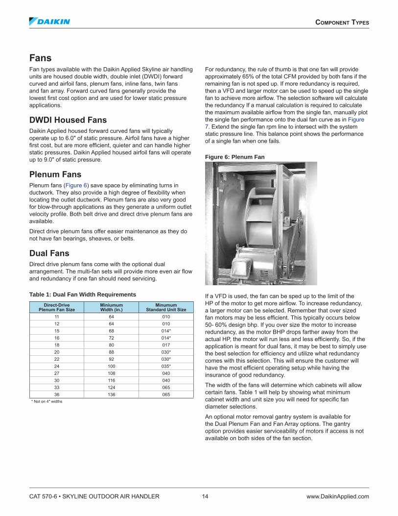
Plenum Fans
Plenum fans (Figure 6) save space by eliminating turns in ductwork. They also provide a high degree of lexibility when locating the outlet ductwork. Plenum fans are also very good for blow-through applications as they generate a uniform outlet velocity proile. Both belt drive and direct drive plenum fans are available.
Direct drive plenum fans offer easier maintenance as they do not have fan bearings, sheaves, or belts.
Dual Fans
Direct drive plenum fans come with the optional dual arrangement. The multi-fan sets will provide more even air low and redundancy if one fan should need servicing.
Table 1: Dual Fan Width Requirements
Direct-Drive Plenum Fan Size
Miniumum Width (in.)
Minumum Standard Unit Size
11 64 010
12 64 010
15 68 014*
16 72 014*
18 80 017
20 88 030*
22 92 030*
24 100 035*
27 108 040
30 116 040
33 124 065
36 136 065
* Not on 4" widths
For redundancy, the rule of thumb is that one fan will provide approximately 65% of the total CFM provided by both fans if the remaining fan is not sped up. If more redundancy is required, then a VFD and larger motor can be used to speed up the single fan to achieve more airlow. The selection software will calculate the redundancy If a manual calculation is required to calculate the maximum available airlow from the single fan, manually plot the single fan performance onto the dual fan curve as in Figure
7. Extend the single fan rpm line to intersect with the system static pressure line. This balance point shows the performance of a single fan when one fails.
Figure 6: Plenum Fan
If a VFD is used, the fan can be sped up to the limit of the HP of the motor to get more airlow. To increase redundancy, a larger motor can be selected. Remember that over sized fan motors may be less eficient. This typically occurs below 50- 60% design bhp. If you over size the motor to increase redundancy, as the motor BHP drops farther away from the actual HP, the motor will run less and less eficiently. So, if the application is meant for dual fans, it may be best to simply use the best selection for eficiency and utilize what redundancy comes with this selection. This will ensure the customer will have the most eficient operating setup while having the insurance of good redundancy.
The width of the fans will determine which cabinets will allow certain fans. Table 1 will help by showing what minimum cabinet width and unit size you will need for speciic fan diameter selections.
An optional motor removal gantry system is available for the Dual Plenum Fan and Fan Array options. The gantry option provides easier serviceability of motors if access is not available on both sides of the fan section.
CAT 570-6 • SKYLINE OUTDOOR AIR HANDLER 14 www.DaikinApplied.com
ComponenT Types
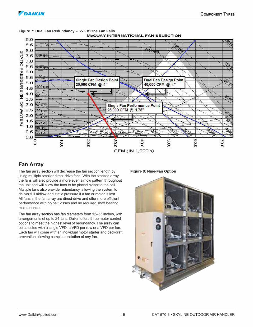
Figure 7: Dual Fan Redundancy – 65% If One Fan Fails
Fan Array
The fan array section will decrease the fan section length by using multiple smaller direct-drive fans. With the stacked array, the fans will also provide a more even airlow pattern throughout the unit and will allow the fans to be placed closer to the coil. Multiple fans also provide redundancy, allowing the system to deliver full airlow and static pressure if a fan or motor is lost. All fans in the fan array are direct-drive and offer more eficient performance with no belt losses and no required shaft bearing maintenance.
The fan array section has fan diameters from 12–33 inches, with arrangements of up to 24 fans. Daikin offers three motor control options to meet the highest level of redundancy. The array can be selected with a single VFD, a VFD per row or a VFD per fan. Each fan will come with an individual motor starter and backdraft prevention allowing complete isolation of any fan.
Figure 8: Nine-Fan Option
ComponenT Types
www.DaikinApplied.com 15 CAT 570-6 • SKYLINE OUTDOOR AIR HANDLER
Coils The Daikin Applied Skyline outdoor air handler offers broad application lexibility in coil sections and coils. Coils can be arranged in draw-through or blow-through conigurations. Heating only, cooling only, or cooling and heating sections are available. All coils are installed with space between each coil to allow access for cleaning and mounting of controls.
Cooling coil sections, and cooling and heating coil sections, are available in seven different section lengths to accommodate every application requirement. Drain pans extend the full length of the section. Removable access panels or doors may be provided in the deeper sections that will not interfere with piping connections extending through the unit side panels or piping vestibules.
All cooling coils are mounted over a double sloped drain pan. The cooling coil rests on coil supports located over the drain pan. The drain pan extends beyond the leaving side of the coil to help recover condensate. The primary drain pan also extends under the coil headers and return bends to help remove condensate from the unit. A full thickness of insulation is always provided between the drain pan and the bottom outer panel. The drain pan is sloped in two planes to promote proper condensate removal. The galvanized drain pan is coated with an antimicrobial treatment as standard to further inhibit the growth of algae and fungi. A stainless steel drain pan is also available as an option.
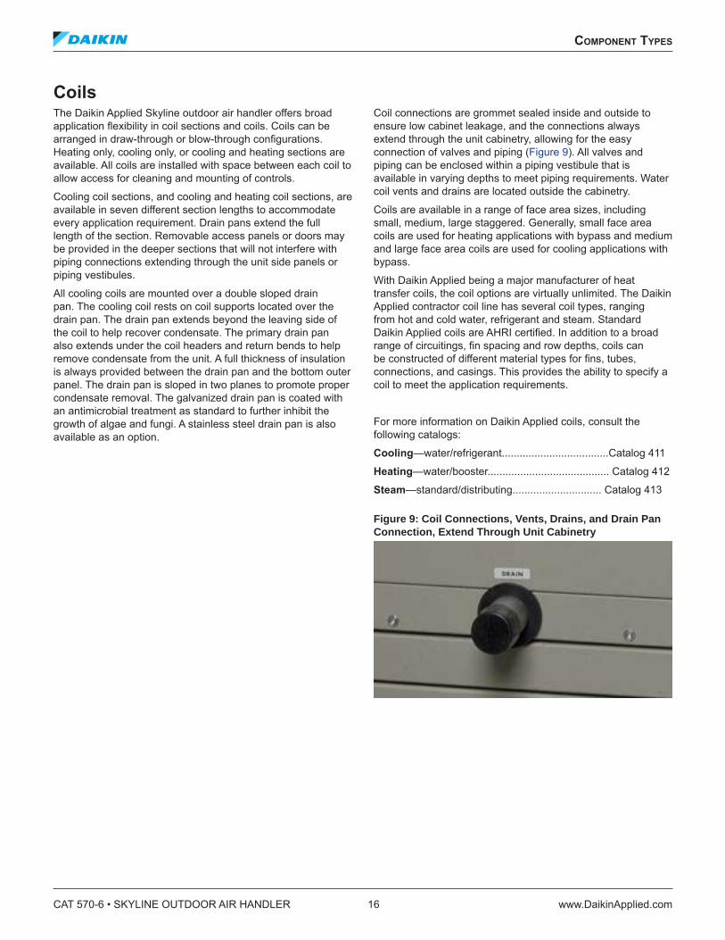
Coil connections are grommet sealed inside and outside to ensure low cabinet leakage, and the connections always extend through the unit cabinetry, allowing for the easy connection of valves and piping (Figure 9). All valves and piping can be enclosed within a piping vestibule that is available in varying depths to meet piping requirements. Water coil vents and drains are located outside the cabinetry.
Coils are available in a range of face area sizes, including small, medium, large staggered. Generally, small face area coils are used for heating applications with bypass and medium and large face area coils are used for cooling applications with bypass.
With Daikin Applied being a major manufacturer of heat transfer coils, the coil options are virtually unlimited. The Daikin Applied contractor coil line has several coil types, ranging from hot and cold water, refrigerant and steam. Standard Daikin Applied coils are AHRI certiied. In addition to a broad range of circuitings, in spacing and row depths, coils can be constructed of different material types for ins, tubes, connections, and casings. This provides the ability to specify a coil to meet the application requirements.
For more information on Daikin Applied coils, consult the following catalogs:
Cooling—water/refrigerant....................................Catalog 411
Heating—water/booster......................................... Catalog 412
Steam—standard/distributing.............................. Catalog 413
Figure 9: Coil Connections, Vents, Drains, and Drain Pan Connection, Extend Through Unit Cabinetry
CAT 570-6 • SKYLINE OUTDOOR AIR HANDLER 16 www.DaikinApplied.com
ComponenT Types
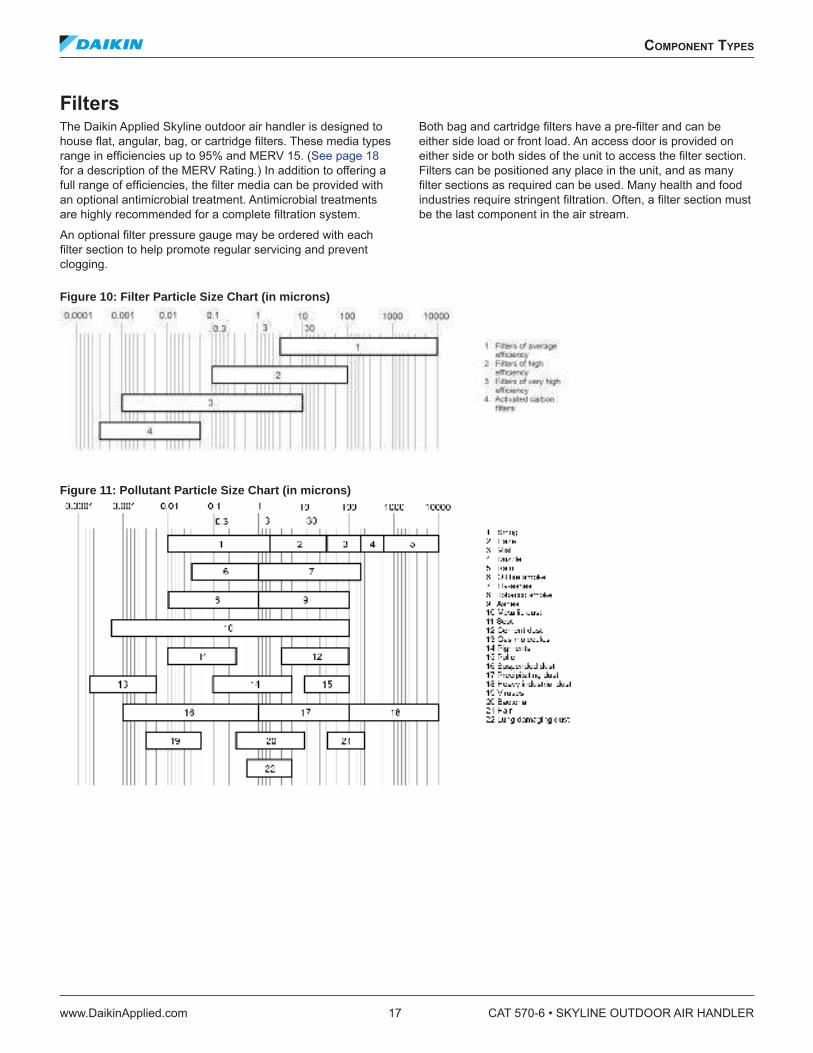
Filters The Daikin Applied Skyline outdoor air handler is designed to house lat, angular, bag, or cartridge ilters. These media types range in eficiencies up to 95% and MERV 15. (See page 18
for a description of the MERV Rating.) In addition to offering a full range of eficiencies, the ilter media can be provided with an optional antimicrobial treatment. Antimicrobial treatments are highly recommended for a complete iltration system.
An optional ilter pressure gauge may be ordered with each ilter section to help promote regular servicing and prevent clogging.
Both bag and cartridge ilters have a pre-ilter and can be either side load or front load. An access door is provided on either side or both sides of the unit to access the ilter section. Filters can be positioned any place in the unit, and as many ilter sections as required can be used. Many health and food industries require stringent iltration. Often, a ilter section must be the last component in the air stream.
Figure 10: Filter Particle Size Chart (in microns)
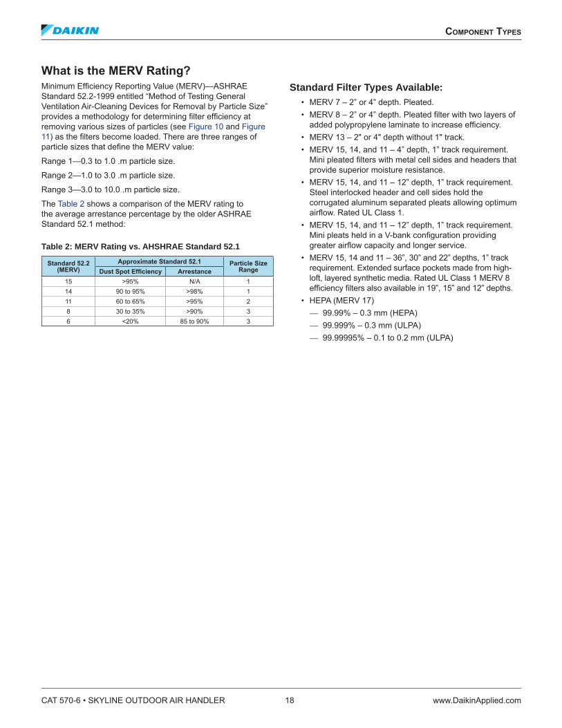
Figure 11: Pollutant Particle Size Chart (in microns)
ComponenT Types
www.DaikinApplied.com 17 CAT 570-6 • SKYLINE OUTDOOR AIR HANDLER
What is the MERV Rating?
Minimum Eficiency Reporting Value (MERV)—ASHRAE Standard 52.2-1999 entitled “Method of Testing General Ventilation Air-Cleaning Devices for Removal by Particle Size” provides a methodology for determining ilter eficiency at removing various sizes of particles (see Figure 10 and Figure
11) as the ilters become loaded. There are three ranges of particle sizes that deine the MERV value:
Range 1—0.3 to 1.0 .m particle size.
Range 2—1.0 to 3.0 .m particle size.
Range 3—3.0 to 10.0 .m particle size.
The Table 2 shows a comparison of the MERV rating to the average arrestance percentage by the older ASHRAE Standard 52.1 method:
Table 2: MERV Rating vs. AHSHRAE Standard 52.1
Standard 52.2 (MERV)
Approximate Standard 52.1 Particle Size RangeDust Spot Eficiency Arrestance
15 >95% N/A 1
14 90 to 95% >98% 1
11 60 to 65% >95% 2
8 30 to 35% >90% 3
6 <20% 85 to 90% 3
Standard Filter Types Available: • MERV 7 – 2” or 4” depth. Pleated. • MERV 8 – 2” or 4” depth. Pleated ilter with two layers of
added polypropylene laminate to increase eficiency. • MERV 13 – 2ʺ or 4ʺ depth without 1ʺ track.• MERV 15, 14, and 11 – 4” depth, 1” track requirement.
Mini pleated ilters with metal cell sides and headers that provide superior moisture resistance.
• MERV 15, 14, and 11 – 12” depth, 1” track requirement. Steel interlocked header and cell sides hold the corrugated aluminum separated pleats allowing optimum airlow. Rated UL Class 1.
• MERV 15, 14, and 11 – 12” depth, 1” track requirement. Mini pleats held in a V-bank coniguration providing greater airlow capacity and longer service.
• MERV 15, 14 and 11 – 36”, 30” and 22” depths, 1” track requirement. Extended surface pockets made from high-loft, layered synthetic media. Rated UL Class 1 MERV 8 eficiency ilters also available in 19”, 15” and 12” depths.
• HEPA (MERV 17) — 99.99% – 0.3 mm (HEPA) — 99.999% – 0.3 mm (ULPA) — 99.99995% – 0.1 to 0.2 mm (ULPA)
CAT 570-6 • SKYLINE OUTDOOR AIR HANDLER 18 www.DaikinApplied.com
ComponenT Types
Access Access sections can be selected to meet speciic application criteria. They can be placed anywhere in a unit in a variety of depths and are available in depths of 16", 24", 30", 36", 42", 48", and 54". Typically, access sections are used for ield-installed components, air monitoring devices, or to provide ample space between components.
Mixing Boxes and Economizers When outside and return air mixing is required, either a mixing box or an economizer section can be selected. Either component will regulate the amount of outside and return air supplied to the conditioned space. The mixing box or economizer can make use of free cooling by opening outside air dampers when the ambient air will help to condition the supply air stream. Additionally, dampers may be individually sized to provide better mixing.
Both the mixing box and economizer are provided with a Daikin Applied UltraSeal low leak damper. This damper has one of the lowest leakage rates in the industry, maximizing energy eficiency. At 4.0" static pressure and a face velocity of 1100 fpm through the dampers, the leakage rate is less than 0.2% (it is common to specify leakage rates at higher static pressures, but dampers should not exceed 2" of static pressure). The parallel airfoil blades are hollow core and fully gasketed. Continuous vinyl seals are provided between the damper blades. Stainless steel end seals and linkage built into high strength ABS plastic endcaps provide smooth, quiet operation. Mixing boxes or economizers used on Daikin Applied Skyline outdoor air handlers can include optional factory-installed rain hoods.
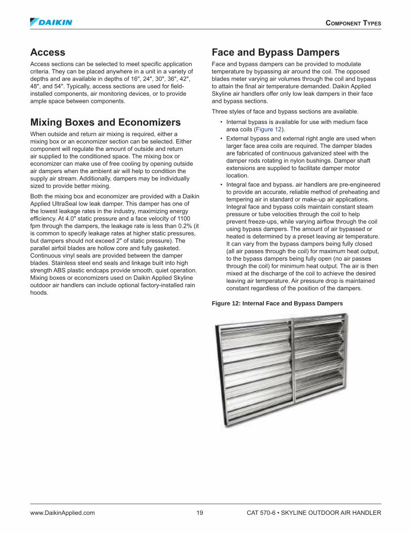
Face and Bypass Dampers Face and bypass dampers can be provided to modulate temperature by bypassing air around the coil. The opposed blades meter varying air volumes through the coil and bypass to attain the inal air temperature demanded. Daikin Applied Skyline air handlers offer only low leak dampers in their face and bypass sections.
Three styles of face and bypass sections are available.
• Internal bypass is available for use with medium face area coils (Figure 12).
• External bypass and external right angle are used when larger face area coils are required. The damper blades are fabricated of continuous galvanized steel with the damper rods rotating in nylon bushings. Damper shaft extensions are supplied to facilitate damper motor location.
• Integral face and bypass. air handlers are pre-engineered to provide an accurate, reliable method of preheating and tempering air in standard or make-up air applications. Integral face and bypass coils maintain constant steam pressure or tube velocities through the coil to help prevent freeze-ups, while varying airlow through the coil using bypass dampers. The amount of air bypassed or heated is determined by a preset leaving air temperature. It can vary from the bypass dampers being fully closed (all air passes through the coil) for maximum heat output, to the bypass dampers being fully open (no air passes through the coil) for minimum heat output. The air is then mixed at the discharge of the coil to achieve the desired leaving air temperature. Air pressure drop is maintained constant regardless of the position of the dampers.
Figure 12: Internal Face and Bypass Dampers
ComponenT Types
www.DaikinApplied.com 19 CAT 570-6 • SKYLINE OUTDOOR AIR HANDLER
Blenders/Air Mixers Stratiication can occur from the mixing box when airlow from two different temperature air streams do not mix completely. This incomplete mixing can continue through the air handler and subject an unprotected coil (no glycol) to freezing temperatures, damaging the coil. With the increased minimum outdoor air requirements as identiied by ASHRAE Standard 62, the likelihood for air stratiication increases. An air handler must be able to handle the required amount of outdoor air, regardless of temperature, without risking damage to the coil.
Blenders/air mixers help to provide protection for coils against freeze-up due to stratiication. They add additional turbulence to the passing air streams, boosting the air velocity for improved mixing. Proper distance is provided immediately downstream to give the air streams enough time to fully mix before reaching the next air handler component. Because blenders/air mixers are static devices, they require no maintenance. Different blender/air mixer lengths can be selected to satisfy either the acoustic, space, pressure drop, or initial cost requirements. The Daikin SelectTools software can help select the appropriate blender/air mixer for the application.
Figure 13: Blender
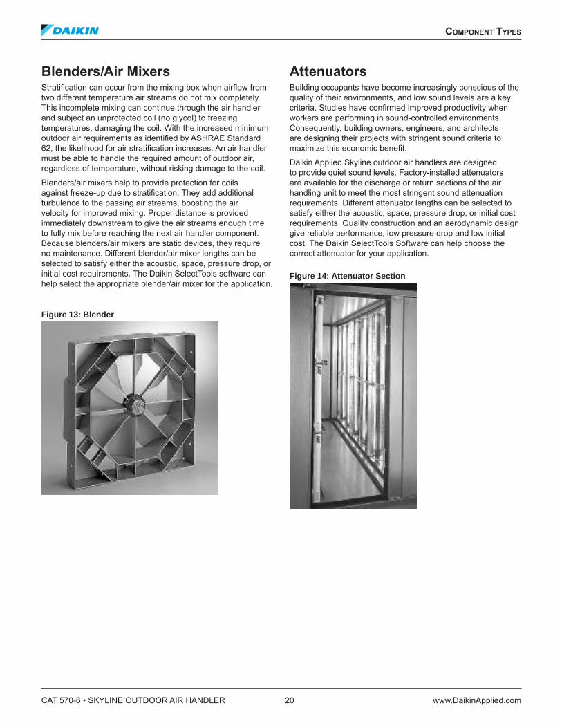
Attenuators Building occupants have become increasingly conscious of the quality of their environments, and low sound levels are a key criteria. Studies have conirmed improved productivity when workers are performing in sound-controlled environments. Consequently, building owners, engineers, and architects are designing their projects with stringent sound criteria to maximize this economic beneit.
Daikin Applied Skyline outdoor air handlers are designed to provide quiet sound levels. Factory-installed attenuators are available for the discharge or return sections of the air handling unit to meet the most stringent sound attenuation requirements. Different attenuator lengths can be selected to satisfy either the acoustic, space, pressure drop, or initial cost requirements. Quality construction and an aerodynamic design give reliable performance, low pressure drop and low initial cost. The Daikin SelectTools Software can help choose the correct attenuator for your application.
Figure 14: Attenuator Section
CAT 570-6 • SKYLINE OUTDOOR AIR HANDLER 20 www.DaikinApplied.com
ComponenT Types
air handler seleCTion
Selecting lexible Skyline outdoor air handlers depends on many different criteria. The Quick Select tables on page 22
and page 23 provide a rough determination of air handler needs. To simplify this process, Daikin Applied designed an innovative computerized selection program—Daikin SelectTools software. It allows the user to develop an air handler from the ground up and obtain all of the detail required for proper design and speciication. The user can design a unit in a matter of minutes.
The program is completely integrated. All input data is carried through the selection process and considered as calculations are made. Because the program is integrated, the opportunity for errors is reduced. The software guides the user through the selection process. On-line editing helps select only viable options. The program is provided so that even the less experienced user can select air handlers accurately.
Designing an eficient air handler system depends on accurate system design and proper equipment selection. Factors that affect unit selection include applicable codes, ventilation requirements, heating and cooling space loads, acceptable temperature differentials, and thermal media and installation limitations. Unit selection can be broken down into four steps: unit type and size, coils, accessories, and fan and motor requirements.
Generally, the unit is selected based on the air volume required and the desired face velocity through the cooling coil. For cooling coils, 400 to 525 feet per minute is considered the optimum face velocity range for dehumidiication and the prevention of any moisture carryover. The Daikin SelectTools software recommends the unit size based on air low and face velocity requirements. Once the unit size is determined, select the coils and all accessory components. Once all components and coils are selected (identifying the total internal component pressure drop), select the fan.
Selecting Coils The Skyline air handler provides the ability to select from multiple face area coils per unit size. Once the coil size is selected, the row and in requirements can be determined based on performance criteria. Daikin Applied offers an extensive line of coil types and circuitings. This wide variety of circuiting, row, and in spacing, in addition to different material types, can provide a coil selection that handles the load required.
Heating, cooling, and combination cooling and reheat sections are available. Coil sections come in many different depths to accommodate multiple rows of coils, and to provide access on the leaving air side or between coils for cleaning and inspection of the drain pan. Access in the coil section can be minimized or maximized depending on the space available and job needs. Coil sections can be placed as needed in the unit, and as many sections as required for conditioning of air can be provided.
Selecting Accessories A complete selection of component and section types in a variety of unit arrangements and conigurations is available for air mixing, iltration, and temperature control to meet speciic application requirements. The outside and/or return air can be brought into the unit through a plenum, mixing box, or economizer. For mixing of the two air streams, dampers are required to modulate and direct outside and return air, which is accomplished using a mixing box or economizer. Both section types use the Daikin Applied patented UltraSeal low leak dampers. Blenders/air mixers also are available to provide proper mixing of two air streams, to prevent stratiication and to help avoid damage to equipment due to freezing temperatures.
To promote good air iltration, many different ilter media types and arrangements are offered. Filters can be provided in angular or lat ilter racks, a variety of media eficiencies, and with or without a preilter. The ilter section can be located anywhere in the unit to ilter air as it enters the unit, or in a inal ilter arrangement before it leaves the unit. Bag or cartridge ilters can be either front or side loading.
Also available are many different size access sections for ield-installed components or to provide access between components. Other options include diffusers, plenums, face and bypass dampers, sound attenuators, and blenders/air mixers. Standard access doors open outward for maximum accessibility to internal components.
Selecting Fans Fan selection requires an accurate calculation of the resistance to the airlow through the entire system. This total resistance consists of the sum of two parts—the external and internal static pressure. The external static pressure is the static pressure found in the distribution system, external to the air handler. The internal unit resistance is the sum of the resistance of the coils and various other unit components and accessories. Component pressure drops are listed for speciic air lows in this catalog.
Use the Daikin SelectTools software to determine internal component pressure drops of the system. Once the total static pressure is known, the software identiies the fans available to properly handle the air low and static pressure for the system. The software generates a full fan curve based on the fan selection and point of operation.
WARNING
SMOKE CONTROL AND MANAGEMENT SYSTEMS
Improper smoke or fume air handling can result in severe personal injury or death. A registered professional engineer must design and approve the air conditioner and air handler application to make sure smoke and fume control meet local ire codes and NFPA requirements for the speciic building application.
air handler seleCTion
www.DaikinApplied.com 21 CAT 570-6 • SKYLINE OUTDOOR AIR HANDLER
quiCk seleCT Tables
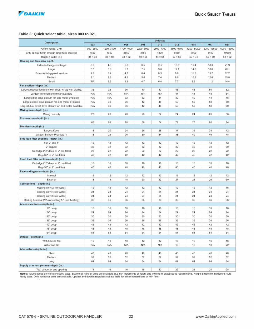
Table 3: Quick select table, sizes 003 to 021
Description Unit size
003 004 006 008 010 012 014 017 021
Airlow range, CFM 900–2500 1200–3100 1700–4600 2200–6000 2900–7700 3600–9700 4200–11200 5000–13500 6000–16000CFM @ 500 ft/min through large face area coil 1550 1950 2850 3750 4800 6050 7000 8400 10050
Height × width (in.) 34 × 38 38 × 40 38 × 52 40 × 58 44 × 64 50 × 66 50 × 74 52 × 80 58 × 82Cooling coil face area, sq. ft.
Extended/staggered large 3.9 4.8 6.6 8.5 10.7 13.5 15.4 18.3 21.9
Large 3.1 3.9 5.7 7.5 9.6 12.1 14.0 16.8 20.1
Extended/staggered medium 2.6 3.4 4.7 6.4 8.3 9.8 11.2 13.7 17.2
Medium 2.1 2.8 4.1 5.6 7.4 8.8 10.2 12.6 15.8
Small NA 2.3 3.3 4.7 6.4 7.7 8.9 11.2 14.4
Fan section—depth (in.)Largest housed fan and motor avail. w/ top hor. dischg. 32 32 36 40 40 46 46 50 52
Largest inline fan and motor available N/A N/A N/A N/A N/A 44 44 48 54
Largest belt drive plenum fan and motor available N/A N/A 32 32 34 40 40 44 48
Largest direct drive plenum fan and motor available N/A 36 36 42 46 50 50 58 60
Largest dual direct drive plenum fan and motor available N/A 36 36 42 46 50 50 58 60
Mixing box—depth (in.)Mixing box only 20 20 20 20 22 24 24 26 30
Economizer—depth (in.)66 66 70 66 74 72 77 80 84
Blender—depth (in.)Largest Kees 18 20 24 26 28 34 36 38 42
Largest Blender Products IV 18 22 26 30 34 38 40 46 48
Side load ilter sections—depth (in.)Flat 2" and 4" 12 12 12 12 12 12 12 12 12
2" angular 32 32 32 32 32 32 32 30 30
Cartridge (12" deep w/ 2" pre-ilter) 22 22 22 22 22 22 22 22 22
Bag (36" w/ 2" pre-ilter) 42 42 42 42 42 42 42 42 42
Front load ilter sections—depth (in.)Cartridge (12" deep w/ 2" pre-ilter) 16 16 16 16 16 16 16 16 16
Bag (36" w/ 2" pre-ilter) 40 40 40 40 40 40 40 40 40
Face and bypass—depth (in.)Internal 12 12 12 12 12 12 12 12 12
External 18 18 18 20 22 24 24 26 30
Coil sections—depth (in.)Heating only (2-row water) 12 12 12 12 12 12 12 12 16
Cooling only (4-row water) 24 24 24 24 24 24 24 24 24
Cooling only (6-row water) 24 24 24 24 24 24 24 24 24
Cooling & reheat (12-row cooling & 1-row heating) 36 36 36 36 36 36 36 36 36
Access sections—depth (in.)16" deep 16 16 16 16 16 16 16 16 16
24" deep 24 24 24 24 24 24 24 24 24
30" deep 30 30 30 30 30 30 30 30 30
36" deep 36 36 36 36 36 36 36 36 36
42" deep 42 42 42 42 42 42 42 42 42
48" deep 48 48 48 48 48 48 48 48 48
54" deep 54 54 54 54 54 54 54 54 54
Diffuse—depth (in.)With housed fan 10 10 10 12 12 16 16 16 16
With inline fan N/A N/A N/A N/A N/A 18 18 18 22
Attenuator—depth (in.)Short 40 40 40 40 40 40 40 40 40
Medium 52 52 52 52 52 52 52 52 52
Long 64 64 64 64 64 64 64 64 64
Supply or return plenum—depth (in.)Top, bottom or end opening 14 16 16 18 20 22 22 24 28
Notes: Values based on typical industry sizes. Skyline air handler units are available in 2-inch increments of height and width to it exact space requirements. Height dimension includes 6" curb-ready base. Only horizontal units are available. Upblast and downblast poises not available for either housed fans or twin fans.
CAT 570-6 • SKYLINE OUTDOOR AIR HANDLER 22 www.DaikinApplied.com
quiCk seleCT Tables
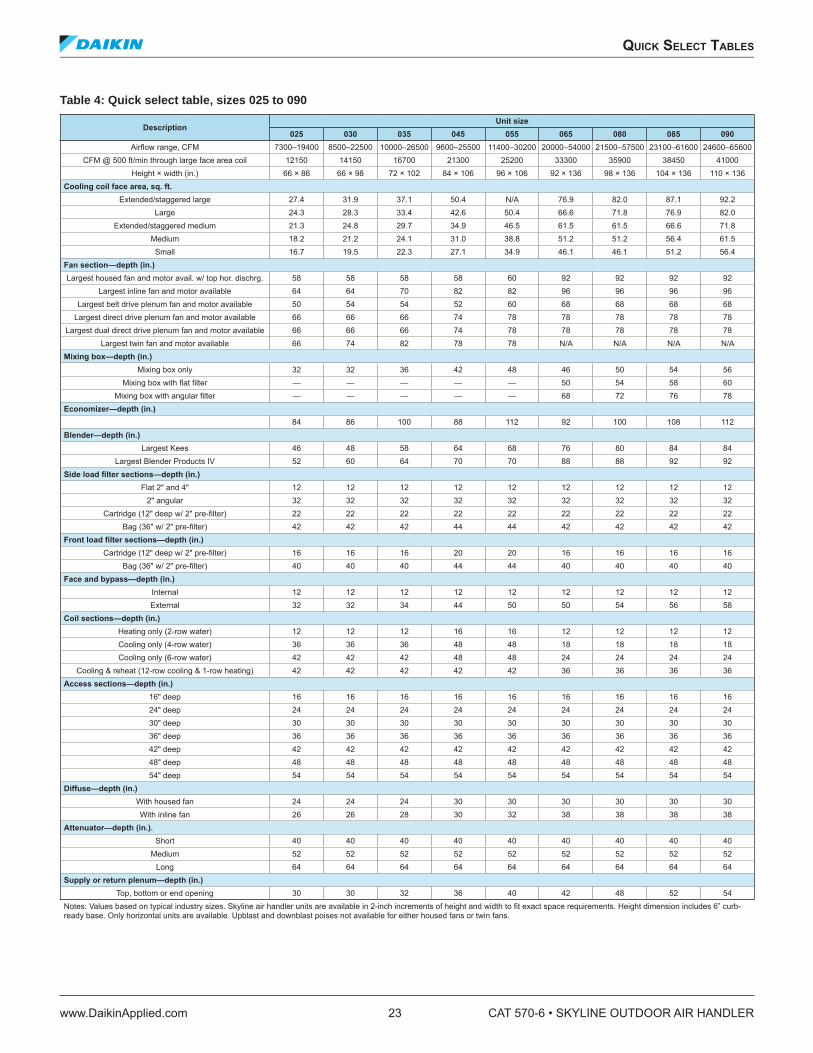
Table 4: Quick select table, sizes 025 to 090
Description Unit size
025 030 035 045 055 065 080 085 090
Airlow range, CFM 7300–19400 8500–22500 10000–26500 9600–25500 11400–30200 20000–54000 21500–57500 23100–61600 24600–65600CFM @ 500 ft/min through large face area coil 12150 14150 16700 21300 25200 33300 35900 38450 41000
Height × width (in.) 66 × 86 66 × 98 72 × 102 84 × 106 96 × 106 92 × 136 98 × 136 104 × 136 110 × 136Cooling coil face area, sq. ft.
Extended/staggered large 27.4 31.9 37.1 50.4 N/A 76.9 82.0 87.1 92.2
Large 24.3 28.3 33.4 42.6 50.4 66.6 71.8 76.9 82.0
Extended/staggered medium 21.3 24.8 29.7 34.9 46.5 61.5 61.5 66.6 71.8
Medium 18.2 21.2 24.1 31.0 38.8 51.2 51.2 56.4 61.5
Small 16.7 19.5 22.3 27.1 34.9 46.1 46.1 51.2 56.4
Fan section—depth (in.)Largest housed fan and motor avail. w/ top hor. dischrg. 58 58 58 58 60 92 92 92 92
Largest inline fan and motor available 64 64 70 82 82 96 96 96 96
Largest belt drive plenum fan and motor available 50 54 54 52 60 68 68 68 68
Largest direct drive plenum fan and motor available 66 66 66 74 78 78 78 78 78
Largest dual direct drive plenum fan and motor available 66 66 66 74 78 78 78 78 78
Largest twin fan and motor available 66 74 82 78 78 N/A N/A N/A N/AMixing box—depth (in.)
Mixing box only 32 32 36 42 48 46 50 54 56
Mixing box with lat ilter — — — — — 50 54 58 60
Mixing box with angular ilter — — — — — 68 72 76 78
Economizer—depth (in.)84 86 100 88 112 92 100 108 112
Blender—depth (in.)Largest Kees 46 48 58 64 68 76 80 84 84
Largest Blender Products IV 52 60 64 70 70 88 88 92 92
Side load ilter sections—depth (in.)Flat 2" and 4" 12 12 12 12 12 12 12 12 12
2" angular 32 32 32 32 32 32 32 32 32
Cartridge (12" deep w/ 2" pre-ilter) 22 22 22 22 22 22 22 22 22
Bag (36" w/ 2" pre-ilter) 42 42 42 44 44 42 42 42 42
Front load ilter sections—depth (in.)Cartridge (12" deep w/ 2" pre-ilter) 16 16 16 20 20 16 16 16 16
Bag (36" w/ 2" pre-ilter) 40 40 40 44 44 40 40 40 40
Face and bypass—depth (in.)Internal 12 12 12 12 12 12 12 12 12
External 32 32 34 44 50 50 54 56 58
Coil sections—depth (in.)Heating only (2-row water) 12 12 12 16 16 12 12 12 12
Cooling only (4-row water) 36 36 36 48 48 18 18 18 18
Cooling only (6-row water) 42 42 42 48 48 24 24 24 24
Cooling & reheat (12-row cooling & 1-row heating) 42 42 42 42 42 36 36 36 36
Access sections—depth (in.)16" deep 16 16 16 16 16 16 16 16 16
24" deep 24 24 24 24 24 24 24 24 24
30" deep 30 30 30 30 30 30 30 30 30
36" deep 36 36 36 36 36 36 36 36 36
42" deep 42 42 42 42 42 42 42 42 42
48" deep 48 48 48 48 48 48 48 48 48
54" deep 54 54 54 54 54 54 54 54 54
Diffuse—depth (in.)With housed fan 24 24 24 30 30 30 30 30 30
With inline fan 26 26 28 30 32 38 38 38 38
Attenuator—depth (in.).Short 40 40 40 40 40 40 40 40 40
Medium 52 52 52 52 52 52 52 52 52
Long 64 64 64 64 64 64 64 64 64
Supply or return plenum—depth (in.)Top, bottom or end opening 30 30 32 36 40 42 48 52 54
Notes: Values based on typical industry sizes. Skyline air handler units are available in 2-inch increments of height and width to it exact space requirements. Height dimension includes 6” curb-ready base. Only horizontal units are available. Upblast and downblast poises not available for either housed fans or twin fans.
quiCk seleCT Tables
www.DaikinApplied.com 23 CAT 570-6 • SKYLINE OUTDOOR AIR HANDLER
appliCaTion ConsideraTions
Installation Flexibility Daikin Applied central station Skyline air handlers feature sectionalized design and can ship fully assembled or in sections as required by the job site condition to provide maximum installation lexibility. Multiple fan, coil, ilter, mixing box, face and bypass, and access components allow the design lexibility of built-up systems with the cost advantage of factory fabricated units.
Unit Location The structural engineer should be involved to verify that the roof has adequate strength and ability to minimize delection. Exercise extreme caution when using a wooden roof structure. Locate units away from building lue stacks or exhaust ventilators to prevent possible entry of contaminated air through the outside air intake. Allow suficient space around the unit for service clearance.
Locating the unit away from occupied spaces and over utility areas, corridors, and auxiliary spaces helps reduce the transmission of sound and vibration to occupied spaces. A concrete deck or pad is recommended when the unit is located over an occupied space where good acoustics are essential.
Curb Installation The roof curb is ield assembled and must be installed level (within 1/16 in. per foot, side to side). In applications involving pitched roofs, the contractor must construct a sub-base. Gaskets are furnished and must be installed between the unit and curb. For proper installation, follow NRCA guidelines. In applications requiring post and rail installation, an I-beam securely mounted on multiple posts should support the unit on each side.
Applications in geographic areas that are subjected to seismic or hurricane conditions must meet code requirements for fastening the unit to the curb and the curb to the building structure.
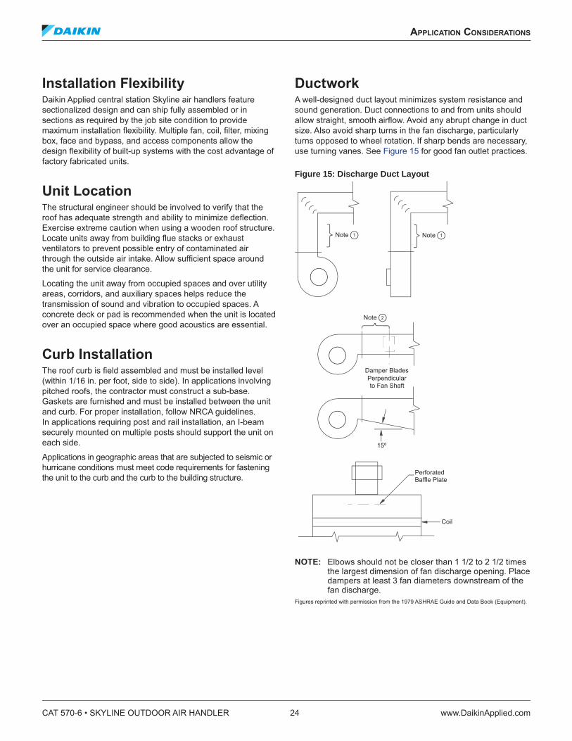
Ductwork A well-designed duct layout minimizes system resistance and sound generation. Duct connections to and from units should allow straight, smooth airlow. Avoid any abrupt change in duct size. Also avoid sharp turns in the fan discharge, particularly turns opposed to wheel rotation. If sharp bends are necessary, use turning vanes. See Figure 15 for good fan outlet practices.
Figure 15: Discharge Duct Layout
NOTE: Elbows should not be closer than 1 1/2 to 2 1/2 times the largest dimension of fan discharge opening. Place dampers at least 3 fan diameters downstream of the fan discharge.
Figures reprinted with permission from the 1979 ASHRAE Guide and Data Book (Equipment).
CAT 570-6 • SKYLINE OUTDOOR AIR HANDLER 24 www.DaikinApplied.com
appliCaTion ConsideraTions

Piping and Drain Pan Traps Design and install piping in accordance with accepted industry standards. Do not apply undue stress at the connection to coil headers. Support pipe work independently of the coils with adequate piping lexibility for thermal expansion. Run drain lines and traps full size from the drain pan connection. Drain pans must have traps to allow the condensate from the coils to drain freely. On a draw-through unit, the trap depth and the distance between the trap outlet and drain pan outlet should be twice the negative static pressure under normal unit operation. See Figure 16.
Figure 16: Drain Pan Traps
Coil Freeze Protection When applying the Skyline outdoor air handler in geographic areas that experience subfreezing conditions, provide coil freeze protection measures. Subfreezing temperatures can adversely affect water and steam coils during controlled or uncontrolled unit shutdowns and even during unit operation. Some temperature stratiication will occur, particularly at low ambient temperatures. When required, static air mixers/ blenders are available that can signiicantly improve mixing and reduce stratiication. This can result in improved protection against freeze-up.
Glycol is strongly recommended as a positive means of freeze protection for water coils. No control sequence can prevent coil freezing in the event of a power failure or equipment malfunction. During those periods, glycol is the only positive means of freeze protection. When selecting water coils, specify glycol to account for performance differences.
Vibration Isolation To help keep noise and vibration compatible with the intended use of the conditioned air space, apply good acoustical and vibration engineering practices during the early stages of design.
Since most applications require vibration isolation, the Skyline outdoor air handler is available with factory-installed internal isolation. Internally isolated units feature spring or rubber in shear isolators sized speciically for each fan wheel and unit size.
Sound The unit inlet, outlet, and radiated sound levels for each octave band are calculated by the Daikin SelectTools software, based on your speciic application. Sound performance data is derived from testing performed in accordance with AMCA Standard 300. The effects of various components, casework, and unit conigurations are taken into account.
Filters Routinely replace ilters to minimize ilter loading. As ilters get dirty, the ilter pressure drop increases, causing a decrease in airlow. Depending on fan type, this airlow change can be signiicant. The effect of ilter loading is the most critical when using 65% and 95% eficient ilters.
When making a fan selection, in the system total static pressure, include a pressure drop component for ilters since they get dirty. A value midway between clean and dirty ilter ratings is recommended. If a minimum airlow is critical, base the selection of the fan rpm on the minimum airlow at the total static pressure associated with dirty ilters. The motor horsepower then is determined by the selected rpm and the total static pressure assumed for dirty ilters, which yields the largest brake horsepower. Following these recommendations should limit airlow luctuation as the ilters load.
Drain Pan
2P
2P
NegativePressure
appliCaTion ConsideraTions
www.DaikinApplied.com 25 CAT 570-6 • SKYLINE OUTDOOR AIR HANDLER
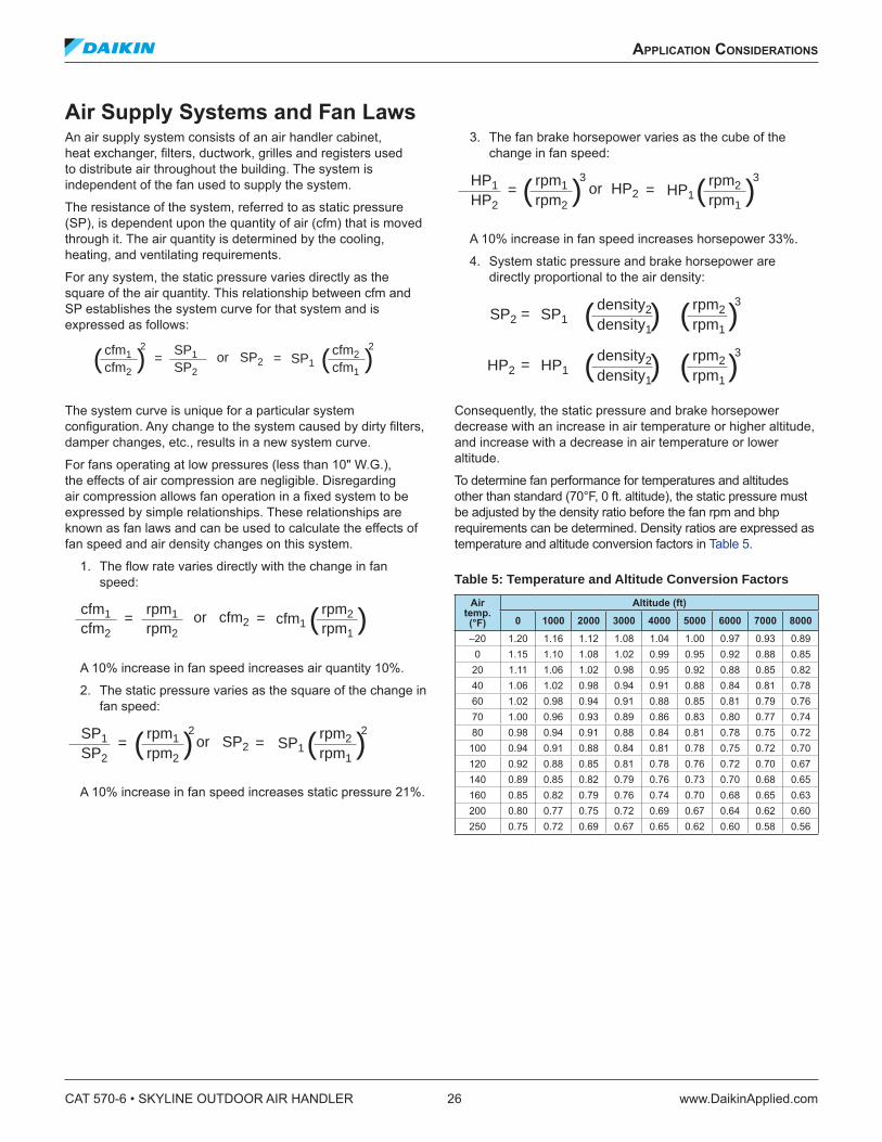
Air Supply Systems and Fan Laws An air supply system consists of an air handler cabinet, heat exchanger, ilters, ductwork, grilles and registers used to distribute air throughout the building. The system is independent of the fan used to supply the system.
The resistance of the system, referred to as static pressure (SP), is dependent upon the quantity of air (cfm) that is moved through it. The air quantity is determined by the cooling, heating, and ventilating requirements.
For any system, the static pressure varies directly as the square of the air quantity. This relationship between cfm and SP establishes the system curve for that system and is expressed as follows:
The system curve is unique for a particular system coniguration. Any change to the system caused by dirty ilters, damper changes, etc., results in a new system curve.
For fans operating at low pressures (less than 10" W.G.), the effects of air compression are negligible. Disregarding air compression allows fan operation in a ixed system to be expressed by simple relationships. These relationships are known as fan laws and can be used to calculate the effects of fan speed and air density changes on this system.
1. The low rate varies directly with the change in fan speed:
A 10% increase in fan speed increases air quantity 10%.
2. The static pressure varies as the square of the change in fan speed:
A 10% increase in fan speed increases static pressure 21%.
3. The fan brake horsepower varies as the cube of the change in fan speed:
A 10% increase in fan speed increases horsepower 33%.
4. System static pressure and brake horsepower are directly proportional to the air density:
Consequently, the static pressure and brake horsepower decrease with an increase in air temperature or higher altitude, and increase with a decrease in air temperature or lower altitude.
To determine fan performance for temperatures and altitudes other than standard (70°F, 0 ft. altitude), the static pressure must be adjusted by the density ratio before the fan rpm and bhp requirements can be determined. Density ratios are expressed as temperature and altitude conversion factors in Table 5.
Table 5: Temperature and Altitude Conversion Factors
Air temp. (°F)
Altitude (ft)
0 1000 2000 3000 4000 5000 6000 7000 8000
–20 1.20 1.16 1.12 1.08 1.04 1.00 0.97 0.93 0.89
0 1.15 1.10 1.08 1.02 0.99 0.95 0.92 0.88 0.85
20 1.11 1.06 1.02 0.98 0.95 0.92 0.88 0.85 0.82
40 1.06 1.02 0.98 0.94 0.91 0.88 0.84 0.81 0.78
60 1.02 0.98 0.94 0.91 0.88 0.85 0.81 0.79 0.76
70 1.00 0.96 0.93 0.89 0.86 0.83 0.80 0.77 0.74
80 0.98 0.94 0.91 0.88 0.84 0.81 0.78 0.75 0.72
100 0.94 0.91 0.88 0.84 0.81 0.78 0.75 0.72 0.70
120 0.92 0.88 0.85 0.81 0.78 0.76 0.72 0.70 0.67
140 0.89 0.85 0.82 0.79 0.76 0.73 0.70 0.68 0.65
160 0.85 0.82 0.79 0.76 0.74 0.70 0.68 0.65 0.63
200 0.80 0.77 0.75 0.72 0.69 0.67 0.64 0.62 0.60
250 0.75 0.72 0.69 0.67 0.65 0.62 0.60 0.58 0.56
cfm1
cfm2=
SP1
SP2SP2or = SP1
cfm2
cfm1)()(
2 2
cfm1
cfm2=
rpm1
rpm2cfm2or = cfm1
rpm2
rpm1)(
SP1
SP2=
rpm1
rpm2SP2or = SP1
rpm2
rpm1)(2
)(2
HP1 HP2
=rpm1
rpm2HP2or = HP1
rpm2
rpm1)(
3
)(3
=density2
density1HP2 HP1 )( rpm2
rpm1)(
3
=density2
density1SP2 SP1 )( rpm2
rpm1)(
3
CAT 570-6 • SKYLINE OUTDOOR AIR HANDLER 26 www.DaikinApplied.com
appliCaTion ConsideraTions
Fan and Motor Heat Motor and drive heat—The total energy input to any fan motor is consumed in two ways: by heat dissipated through the motor frame and by work output. The amount of heat dissipated by the motor is a function of its operating eficiency:
Motor heat = input × (1 – motor eficiency)
A small amount of the motor work output is dissipated by the drive mechanism, which also results in a heat gain. Belt drive losses are a function of belt tension and number of belts as well as power transmitted. Typical belt drive losses range from 2% to 6% of bhp.
Whether motor and drive heat gain become part of an air handling system cooling load depends on the motor location relative to the conditioned space. For air handlers with internal motors, the motor and drive are within the conditioned space. Therefore, the motor and drive add heat to the system. Subtract this heat from the cooling capacity and add it to the heating capacity of the unit.
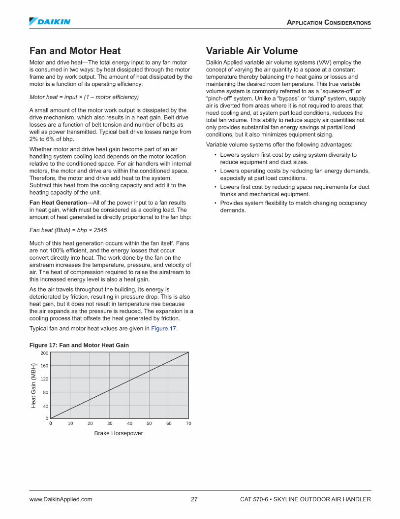
Fan Heat Generation—All of the power input to a fan results in heat gain, which must be considered as a cooling load. The amount of heat generated is directly proportional to the fan bhp:
Fan heat (Btuh) = bhp × 2545
Much of this heat generation occurs within the fan itself. Fans are not 100% eficient, and the energy losses that occur convert directly into heat. The work done by the fan on the airstream increases the temperature, pressure, and velocity of air. The heat of compression required to raise the airstream to this increased energy level is also a heat gain.
As the air travels throughout the building, its energy is deteriorated by friction, resulting in pressure drop. This is also heat gain, but it does not result in temperature rise because the air expands as the pressure is reduced. The expansion is a cooling process that offsets the heat generated by friction.
Typical fan and motor heat values are given in Figure 17.
Figure 17: Fan and Motor Heat Gain
Variable Air Volume Daikin Applied variable air volume systems (VAV) employ the concept of varying the air quantity to a space at a constant temperature thereby balancing the heat gains or losses and maintaining the desired room temperature. This true variable volume system is commonly referred to as a “squeeze-off” or “pinch-off” system. Unlike a “bypass” or “dump” system, supply air is diverted from areas where it is not required to areas that need cooling and, at system part load conditions, reduces the total fan volume. This ability to reduce supply air quantities not only provides substantial fan energy savings at partial load conditions, but it also minimizes equipment sizing.
Variable volume systems offer the following advantages:
• Lowers system irst cost by using system diversity to reduce equipment and duct sizes.
• Lowers operating costs by reducing fan energy demands, especially at part load conditions.
• Lowers irst cost by reducing space requirements for duct trunks and mechanical equipment.
• Provides system lexibility to match changing occupancy demands.
Hea
t Gai
n (M
BH
)
200
160
120
80
40
000 10 20 30 40 50 60 70
Brake Horsepower
appliCaTion ConsideraTions
www.DaikinApplied.com 27 CAT 570-6 • SKYLINE OUTDOOR AIR HANDLER
engineering and physiCal daTa
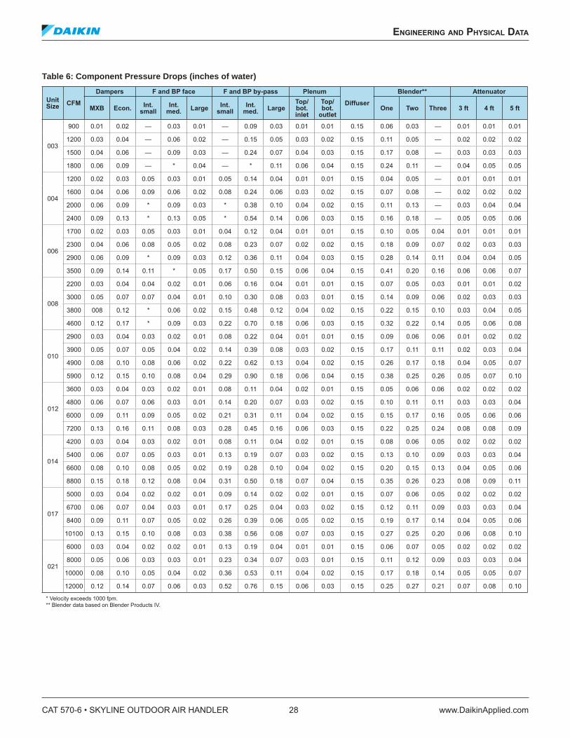
Table 6: Component Pressure Drops (inches of water)
Unit Size
CFM
Dampers F and BP face F and BP by-pass Plenum
Diffuser
Blender** Attenuator
MXB Econ.Int.
smallInt.
med.Large
Int. small
Int. med.
LargeTop/bot.inlet
Top/bot.
outletOne Two Three 3 ft 4 ft 5 ft
003
900 0.01 0.02 — 0.03 0.01 — 0.09 0.03 0.01 0.01 0.15 0.06 0.03 — 0.01 0.01 0.01
1200 0.03 0.04 — 0.06 0.02 — 0.15 0.05 0.03 0.02 0.15 0.11 0.05 — 0.02 0.02 0.02
1500 0.04 0.06 — 0.09 0.03 — 0.24 0.07 0.04 0.03 0.15 0.17 0.08 — 0.03 0.03 0.03
1800 0.06 0.09 — * 0.04 — * 0.11 0.06 0.04 0.15 0.24 0.11 — 0.04 0.05 0.05
004
1200 0.02 0.03 0.05 0.03 0.01 0.05 0.14 0.04 0.01 0.01 0.15 0.04 0.05 — 0.01 0.01 0.01
1600 0.04 0.06 0.09 0.06 0.02 0.08 0.24 0.06 0.03 0.02 0.15 0.07 0.08 — 0.02 0.02 0.02
2000 0.06 0.09 * 0.09 0.03 * 0.38 0.10 0.04 0.02 0.15 0.11 0.13 — 0.03 0.04 0.04
2400 0.09 0.13 * 0.13 0.05 * 0.54 0.14 0.06 0.03 0.15 0.16 0.18 — 0.05 0.05 0.06
006
1700 0.02 0.03 0.05 0.03 0.01 0.04 0.12 0.04 0.01 0.01 0.15 0.10 0.05 0.04 0.01 0.01 0.01
2300 0.04 0.06 0.08 0.05 0.02 0.08 0.23 0.07 0.02 0.02 0.15 0.18 0.09 0.07 0.02 0.03 0.03
2900 0.06 0.09 * 0.09 0.03 0.12 0.36 0.11 0.04 0.03 0.15 0.28 0.14 0.11 0.04 0.04 0.05
3500 0.09 0.14 0.11 * 0.05 0.17 0.50 0.15 0.06 0.04 0.15 0.41 0.20 0.16 0.06 0.06 0.07
008
2200 0.03 0.04 0.04 0.02 0.01 0.06 0.16 0.04 0.01 0.01 0.15 0.07 0.05 0.03 0.01 0.01 0.02
3000 0.05 0.07 0.07 0.04 0.01 0.10 0.30 0.08 0.03 0.01 0.15 0.14 0.09 0.06 0.02 0.03 0.03
3800 008 0.12 * 0.06 0.02 0.15 0.48 0.12 0.04 0.02 0.15 0.22 0.15 0.10 0.03 0.04 0.05
4600 0.12 0.17 * 0.09 0.03 0.22 0.70 0.18 0.06 0.03 0.15 0.32 0.22 0.14 0.05 0.06 0.08
010
2900 0.03 0.04 0.03 0.02 0.01 0.08 0.22 0.04 0.01 0.01 0.15 0.09 0.06 0.06 0.01 0.02 0.02
3900 0.05 0.07 0.05 0.04 0.02 0.14 0.39 0.08 0.03 0.02 0.15 0.17 0.11 0.11 0.02 0.03 0.04
4900 0.08 0.10 0.08 0.06 0.02 0.22 0.62 0.13 0.04 0.02 0.15 0.26 0.17 0.18 0.04 0.05 0.07
5900 0.12 0.15 0.10 0.08 0.04 0.29 0.90 0.18 0.06 0.04 0.15 0.38 0.25 0.26 0.05 0.07 0.10
012
3600 0.03 0.04 0.03 0.02 0.01 0.08 0.11 0.04 0.02 0.01 0.15 0.05 0.06 0.06 0.02 0.02 0.02
4800 0.06 0.07 0.06 0.03 0.01 0.14 0.20 0.07 0.03 0.02 0.15 0.10 0.11 0.11 0.03 0.03 0.04
6000 0.09 0.11 0.09 0.05 0.02 0.21 0.31 0.11 0.04 0.02 0.15 0.15 0.17 0.16 0.05 0.06 0.06
7200 0.13 0.16 0.11 0.08 0.03 0.28 0.45 0.16 0.06 0.03 0.15 0.22 0.25 0.24 0.08 0.08 0.09
014
4200 0.03 0.04 0.03 0.02 0.01 0.08 0.11 0.04 0.02 0.01 0.15 0.08 0.06 0.05 0.02 0.02 0.02
5400 0.06 0.07 0.05 0.03 0.01 0.13 0.19 0.07 0.03 0.02 0.15 0.13 0.10 0.09 0.03 0.03 0.04
6600 0.08 0.10 0.08 0.05 0.02 0.19 0.28 0.10 0.04 0.02 0.15 0.20 0.15 0.13 0.04 0.05 0.06
8800 0.15 0.18 0.12 0.08 0.04 0.31 0.50 0.18 0.07 0.04 0.15 0.35 0.26 0.23 0.08 0.09 0.11
017
5000 0.03 0.04 0.02 0.02 0.01 0.09 0.14 0.02 0.02 0.01 0.15 0.07 0.06 0.05 0.02 0.02 0.02
6700 0.06 0.07 0.04 0.03 0.01 0.17 0.25 0.04 0.03 0.02 0.15 0.12 0.11 0.09 0.03 0.03 0.04
8400 0.09 0.11 0.07 0.05 0.02 0.26 0.39 0.06 0.05 0.02 0.15 0.19 0.17 0.14 0.04 0.05 0.06
10100 0.13 0.15 0.10 0.08 0.03 0.38 0.56 0.08 0.07 0.03 0.15 0.27 0.25 0.20 0.06 0.08 0.10
021
6000 0.03 0.04 0.02 0.02 0.01 0.13 0.19 0.04 0.01 0.01 0.15 0.06 0.07 0.05 0.02 0.02 0.02
8000 0.05 0.06 0.03 0.03 0.01 0.23 0.34 0.07 0.03 0.01 0.15 0.11 0.12 0.09 0.03 0.03 0.04
10000 0.08 0.10 0.05 0.04 0.02 0.36 0.53 0.11 0.04 0.02 0.15 0.17 0.18 0.14 0.05 0.05 0.07
12000 0.12 0.14 0.07 0.06 0.03 0.52 0.76 0.15 0.06 0.03 0.15 0.25 0.27 0.21 0.07 0.08 0.10
* Velocity exceeds 1000 fpm. ** Blender data based on Blender Products IV.
CAT 570-6 • SKYLINE OUTDOOR AIR HANDLER 28 www.DaikinApplied.com
engineering and physiCal daTa
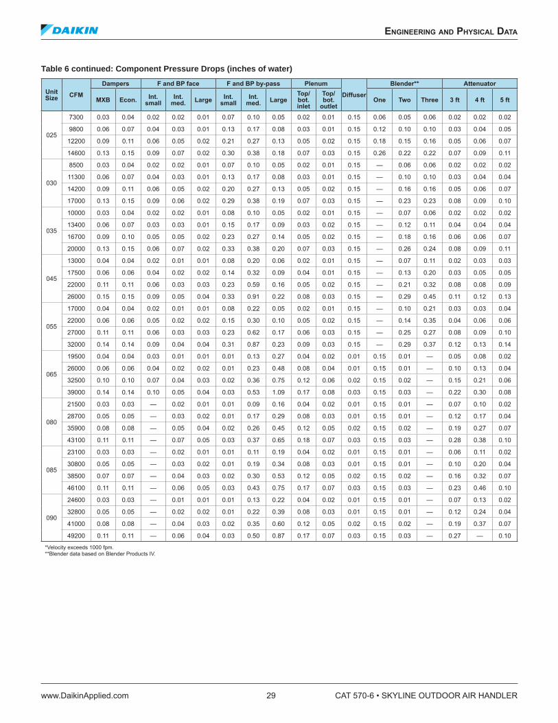
Table 6 continued: Component Pressure Drops (inches of water)
Unit Size
CFM
Dampers F and BP face F and BP by-pass Plenum
Diffuser
Blender** Attenuator
MXB Econ.Int.
small Int.
med.Large
Int. small
Int. med.
Large Top/bot. inlet
Top/bot.
outletOne Two Three 3 ft 4 ft 5 ft
025
7300 0.03 0.04 0.02 0.02 0.01 0.07 0.10 0.05 0.02 0.01 0.15 0.06 0.05 0.06 0.02 0.02 0.02
9800 0.06 0.07 0.04 0.03 0.01 0.13 0.17 0.08 0.03 0.01 0.15 0.12 0.10 0.10 0.03 0.04 0.05
12200 0.09 0.11 0.06 0.05 0.02 0.21 0.27 0.13 0.05 0.02 0.15 0.18 0.15 0.16 0.05 0.06 0.07
14600 0.13 0.15 0.09 0.07 0.02 0.30 0.38 0.18 0.07 0.03 0.15 0.26 0.22 0.22 0.07 0.09 0.11
030
8500 0.03 0.04 0.02 0.02 0.01 0.07 0.10 0.05 0.02 0.01 0.15 — 0.06 0.06 0.02 0.02 0.02
11300 0.06 0.07 0.04 0.03 0.01 0.13 0.17 0.08 0.03 0.01 0.15 — 0.10 0.10 0.03 0.04 0.04
14200 0.09 0.11 0.06 0.05 0.02 0.20 0.27 0.13 0.05 0.02 0.15 — 0.16 0.16 0.05 0.06 0.07
17000 0.13 0.15 0.09 0.06 0.02 0.29 0.38 0.19 0.07 0.03 0.15 — 0.23 0.23 0.08 0.09 0.10
035
10000 0.03 0.04 0.02 0.02 0.01 0.08 0.10 0.05 0.02 0.01 0.15 — 0.07 0.06 0.02 0.02 0.02
13400 0.06 0.07 0.03 0.03 0.01 0.15 0.17 0.09 0.03 0.02 0.15 — 0.12 0.11 0.04 0.04 0.04
16700 0.09 0.10 0.05 0.05 0.02 0.23 0.27 0.14 0.05 0.02 0.15 — 0.18 0.16 0.06 0.06 0.07
20000 0.13 0.15 0.06 0.07 0.02 0.33 0.38 0.20 0.07 0.03 0.15 — 0.26 0.24 0.08 0.09 0.11
045
13000 0.04 0.04 0.02 0.01 0.01 0.08 0.20 0.06 0.02 0.01 0.15 — 0.07 0.11 0.02 0.03 0.03
17500 0.06 0.06 0.04 0.02 0.02 0.14 0.32 0.09 0.04 0.01 0.15 — 0.13 0.20 0.03 0.05 0.05
22000 0.11 0.11 0.06 0.03 0.03 0.23 0.59 0.16 0.05 0.02 0.15 — 0.21 0.32 0.08 0.08 0.09
26000 0.15 0.15 0.09 0.05 0.04 0.33 0.91 0.22 0.08 0.03 0.15 — 0.29 0.45 0.11 0.12 0.13
055
17000 0.04 0.04 0.02 0.01 0.01 0.08 0.22 0.05 0.02 0.01 0.15 — 0.10 0.21 0.03 0.03 0.04
22000 0.06 0.06 0.05 0.02 0.02 0.15 0.30 0.10 0.05 0.02 0.15 — 0.14 0.35 0.04 0.06 0.06
27000 0.11 0.11 0.06 0.03 0.03 0.23 0.62 0.17 0.06 0.03 0.15 — 0.25 0.27 0.08 0.09 0.10
32000 0.14 0.14 0.09 0.04 0.04 0.31 0.87 0.23 0.09 0.03 0.15 — 0.29 0.37 0.12 0.13 0.14
065
19500 0.04 0.04 0.03 0.01 0.01 0.01 0.13 0.27 0.04 0.02 0.01 0.15 0.01 — 0.05 0.08 0.02
26000 0.06 0.06 0.04 0.02 0.02 0.01 0.23 0.48 0.08 0.04 0.01 0.15 0.01 — 0.10 0.13 0.04
32500 0.10 0.10 0.07 0.04 0.03 0.02 0.36 0.75 0.12 0.06 0.02 0.15 0.02 — 0.15 0.21 0.06
39000 0.14 0.14 0.10 0.05 0.04 0.03 0.53 1.09 0.17 0.08 0.03 0.15 0.03 — 0.22 0.30 0.08
080
21500 0.03 0.03 — 0.02 0.01 0.01 0.09 0.16 0.04 0.02 0.01 0.15 0.01 — 0.07 0.10 0.02
28700 0.05 0.05 — 0.03 0.02 0.01 0.17 0.29 0.08 0.03 0.01 0.15 0.01 — 0.12 0.17 0.04
35900 0.08 0.08 — 0.05 0.04 0.02 0.26 0.45 0.12 0.05 0.02 0.15 0.02 — 0.19 0.27 0.07
43100 0.11 0.11 — 0.07 0.05 0.03 0.37 0.65 0.18 0.07 0.03 0.15 0.03 — 0.28 0.38 0.10
085
23100 0.03 0.03 — 0.02 0.01 0.01 0.11 0.19 0.04 0.02 0.01 0.15 0.01 — 0.06 0.11 0.02
30800 0.05 0.05 — 0.03 0.02 0.01 0.19 0.34 0.08 0.03 0.01 0.15 0.01 — 0.10 0.20 0.04
38500 0.07 0.07 — 0.04 0.03 0.02 0.30 0.53 0.12 0.05 0.02 0.15 0.02 — 0.16 0.32 0.07
46100 0.11 0.11 — 0.06 0.05 0.03 0.43 0.75 0.17 0.07 0.03 0.15 0.03 — 0.23 0.46 0.10
090
24600 0.03 0.03 — 0.01 0.01 0.01 0.13 0.22 0.04 0.02 0.01 0.15 0.01 — 0.07 0.13 0.02
32800 0.05 0.05 — 0.02 0.02 0.01 0.22 0.39 0.08 0.03 0.01 0.15 0.01 — 0.12 0.24 0.04
41000 0.08 0.08 — 0.04 0.03 0.02 0.35 0.60 0.12 0.05 0.02 0.15 0.02 — 0.19 0.37 0.07
49200 0.11 0.11 — 0.06 0.04 0.03 0.50 0.87 0.17 0.07 0.03 0.15 0.03 — 0.27 — 0.10
*Velocity exceeds 1000 fpm.**Blender data based on Blender Products IV.
engineering and physiCal daTa
www.DaikinApplied.com 29 CAT 570-6 • SKYLINE OUTDOOR AIR HANDLER
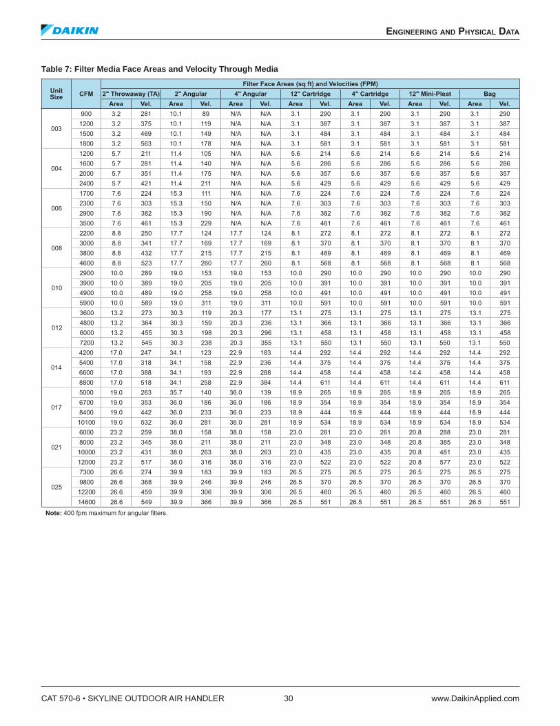
Table 7: Filter Media Face Areas and Velocity Through Media
Unit Size
CFM
Filter Face Areas (sq ft) and Velocities (FPM) 2" Throwaway (TA) 2" Angular 4" Angular 12" Cartridge 4" Cartridge 12" Mini-Pleat Bag
Area Vel. Area Vel. Area Vel. Area Vel. Area Vel. Area Vel. Area Vel.
003
900 3.2 281 10.1 89 N/A N/A 3.1 290 3.1 290 3.1 290 3.1 290
1200 3.2 375 10.1 119 N/A N/A 3.1 387 3.1 387 3.1 387 3.1 387
1500 3.2 469 10.1 149 N/A N/A 3.1 484 3.1 484 3.1 484 3.1 484
1800 3.2 563 10.1 178 N/A N/A 3.1 581 3.1 581 3.1 581 3.1 581
004
1200 5.7 211 11.4 105 N/A N/A 5.6 214 5.6 214 5.6 214 5.6 214
1600 5.7 281 11.4 140 N/A N/A 5.6 286 5.6 286 5.6 286 5.6 286
2000 5.7 351 11.4 175 N/A N/A 5.6 357 5.6 357 5.6 357 5.6 357
2400 5.7 421 11.4 211 N/A N/A 5.6 429 5.6 429 5.6 429 5.6 429
006
1700 7.6 224 15.3 111 N/A N/A 7.6 224 7.6 224 7.6 224 7.6 224
2300 7.6 303 15.3 150 N/A N/A 7.6 303 7.6 303 7.6 303 7.6 303
2900 7.6 382 15.3 190 N/A N/A 7.6 382 7.6 382 7.6 382 7.6 382
3500 7.6 461 15.3 229 N/A N/A 7.6 461 7.6 461 7.6 461 7.6 461
008
2200 8.8 250 17.7 124 17.7 124 8.1 272 8.1 272 8.1 272 8.1 272
3000 8.8 341 17.7 169 17.7 169 8.1 370 8.1 370 8.1 370 8.1 370
3800 8.8 432 17.7 215 17.7 215 8.1 469 8.1 469 8.1 469 8.1 469
4600 8.8 523 17.7 260 17.7 260 8.1 568 8.1 568 8.1 568 8.1 568
010
2900 10.0 289 19.0 153 19.0 153 10.0 290 10.0 290 10.0 290 10.0 290
3900 10.0 389 19.0 205 19.0 205 10.0 391 10.0 391 10.0 391 10.0 391
4900 10.0 489 19.0 258 19.0 258 10.0 491 10.0 491 10.0 491 10.0 491
5900 10.0 589 19.0 311 19.0 311 10.0 591 10.0 591 10.0 591 10.0 591
012
3600 13.2 273 30.3 119 20.3 177 13.1 275 13.1 275 13.1 275 13.1 275
4800 13.2 364 30.3 159 20.3 236 13.1 366 13.1 366 13.1 366 13.1 366
6000 13.2 455 30.3 198 20.3 296 13.1 458 13.1 458 13.1 458 13.1 458
7200 13.2 545 30.3 238 20.3 355 13.1 550 13.1 550 13.1 550 13.1 550
014
4200 17.0 247 34.1 123 22.9 183 14.4 292 14.4 292 14.4 292 14.4 292
5400 17.0 318 34.1 158 22.9 236 14.4 375 14.4 375 14.4 375 14.4 375
6600 17.0 388 34.1 193 22.9 288 14.4 458 14.4 458 14.4 458 14.4 458
8800 17.0 518 34.1 258 22.9 384 14.4 611 14.4 611 14.4 611 14.4 611
017
5000 19.0 263 35.7 140 36.0 139 18.9 265 18.9 265 18.9 265 18.9 265
6700 19.0 353 36.0 186 36.0 186 18.9 354 18.9 354 18.9 354 18.9 354
8400 19.0 442 36.0 233 36.0 233 18.9 444 18.9 444 18.9 444 18.9 444
10100 19.0 532 36.0 281 36.0 281 18.9 534 18.9 534 18.9 534 18.9 534
021
6000 23.2 259 38.0 158 38.0 158 23.0 261 23.0 261 20.8 288 23.0 281
8000 23.2 345 38.0 211 38.0 211 23.0 348 23.0 348 20.8 385 23.0 348
10000 23.2 431 38.0 263 38.0 263 23.0 435 23.0 435 20.8 481 23.0 435
12000 23.2 517 38.0 316 38.0 316 23.0 522 23.0 522 20.8 577 23.0 522
025
7300 26.6 274 39.9 183 39.9 183 26.5 275 26.5 275 26.5 275 26.5 275
9800 26.6 368 39.9 246 39.9 246 26.5 370 26.5 370 26.5 370 26.5 370
12200 26.6 459 39.9 306 39.9 306 26.5 460 26.5 460 26.5 460 26.5 460
14600 26.6 549 39.9 366 39.9 366 26.5 551 26.5 551 26.5 551 26.5 551
Note: 400 fpm maximum for angular ilters.
CAT 570-6 • SKYLINE OUTDOOR AIR HANDLER 30 www.DaikinApplied.com
engineering and physiCal daTa
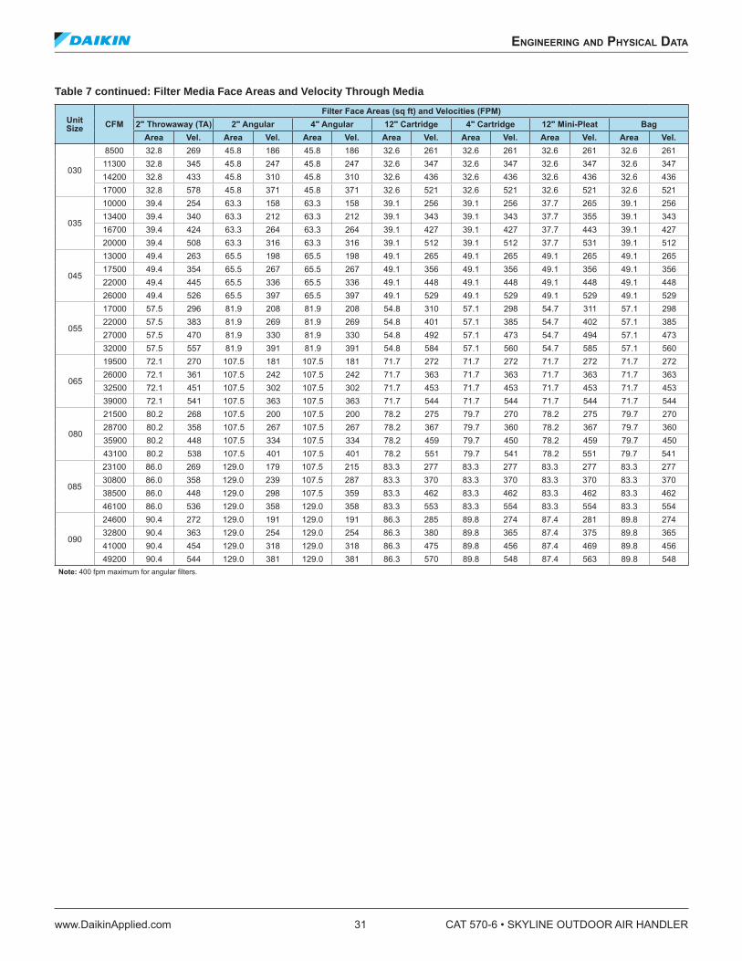
Table 7 continued: Filter Media Face Areas and Velocity Through Media
Unit Size
CFM
Filter Face Areas (sq ft) and Velocities (FPM)2" Throwaway (TA) 2" Angular 4" Angular 12" Cartridge 4" Cartridge 12" Mini-Pleat Bag
Area Vel. Area Vel. Area Vel. Area Vel. Area Vel. Area Vel. Area Vel.
030
8500 32.8 269 45.8 186 45.8 186 32.6 261 32.6 261 32.6 261 32.6 261
11300 32.8 345 45.8 247 45.8 247 32.6 347 32.6 347 32.6 347 32.6 347
14200 32.8 433 45.8 310 45.8 310 32.6 436 32.6 436 32.6 436 32.6 436
17000 32.8 578 45.8 371 45.8 371 32.6 521 32.6 521 32.6 521 32.6 521
035
10000 39.4 254 63.3 158 63.3 158 39.1 256 39.1 256 37.7 265 39.1 256
13400 39.4 340 63.3 212 63.3 212 39.1 343 39.1 343 37.7 355 39.1 343
16700 39.4 424 63.3 264 63.3 264 39.1 427 39.1 427 37.7 443 39.1 427
20000 39.4 508 63.3 316 63.3 316 39.1 512 39.1 512 37.7 531 39.1 512
045
13000 49.4 263 65.5 198 65.5 198 49.1 265 49.1 265 49.1 265 49.1 265
17500 49.4 354 65.5 267 65.5 267 49.1 356 49.1 356 49.1 356 49.1 356
22000 49.4 445 65.5 336 65.5 336 49.1 448 49.1 448 49.1 448 49.1 448
26000 49.4 526 65.5 397 65.5 397 49.1 529 49.1 529 49.1 529 49.1 529
055
17000 57.5 296 81.9 208 81.9 208 54.8 310 57.1 298 54.7 311 57.1 298
22000 57.5 383 81.9 269 81.9 269 54.8 401 57.1 385 54.7 402 57.1 385
27000 57.5 470 81.9 330 81.9 330 54.8 492 57.1 473 54.7 494 57.1 473
32000 57.5 557 81.9 391 81.9 391 54.8 584 57.1 560 54.7 585 57.1 560
065
19500 72.1 270 107.5 181 107.5 181 71.7 272 71.7 272 71.7 272 71.7 272
26000 72.1 361 107.5 242 107.5 242 71.7 363 71.7 363 71.7 363 71.7 363
32500 72.1 451 107.5 302 107.5 302 71.7 453 71.7 453 71.7 453 71.7 453
39000 72.1 541 107.5 363 107.5 363 71.7 544 71.7 544 71.7 544 71.7 544
080
21500 80.2 268 107.5 200 107.5 200 78.2 275 79.7 270 78.2 275 79.7 270
28700 80.2 358 107.5 267 107.5 267 78.2 367 79.7 360 78.2 367 79.7 360
35900 80.2 448 107.5 334 107.5 334 78.2 459 79.7 450 78.2 459 79.7 450
43100 80.2 538 107.5 401 107.5 401 78.2 551 79.7 541 78.2 551 79.7 541
085
23100 86.0 269 129.0 179 107.5 215 83.3 277 83.3 277 83.3 277 83.3 277
30800 86.0 358 129.0 239 107.5 287 83.3 370 83.3 370 83.3 370 83.3 370
38500 86.0 448 129.0 298 107.5 359 83.3 462 83.3 462 83.3 462 83.3 462
46100 86.0 536 129.0 358 129.0 358 83.3 553 83.3 554 83.3 554 83.3 554
090
24600 90.4 272 129.0 191 129.0 191 86.3 285 89.8 274 87.4 281 89.8 274
32800 90.4 363 129.0 254 129.0 254 86.3 380 89.8 365 87.4 375 89.8 365
41000 90.4 454 129.0 318 129.0 318 86.3 475 89.8 456 87.4 469 89.8 456
49200 90.4 544 129.0 381 129.0 381 86.3 570 89.8 548 87.4 563 89.8 548
Note: 400 fpm maximum for angular ilters.
engineering and physiCal daTa
www.DaikinApplied.com 31 CAT 570-6 • SKYLINE OUTDOOR AIR HANDLER
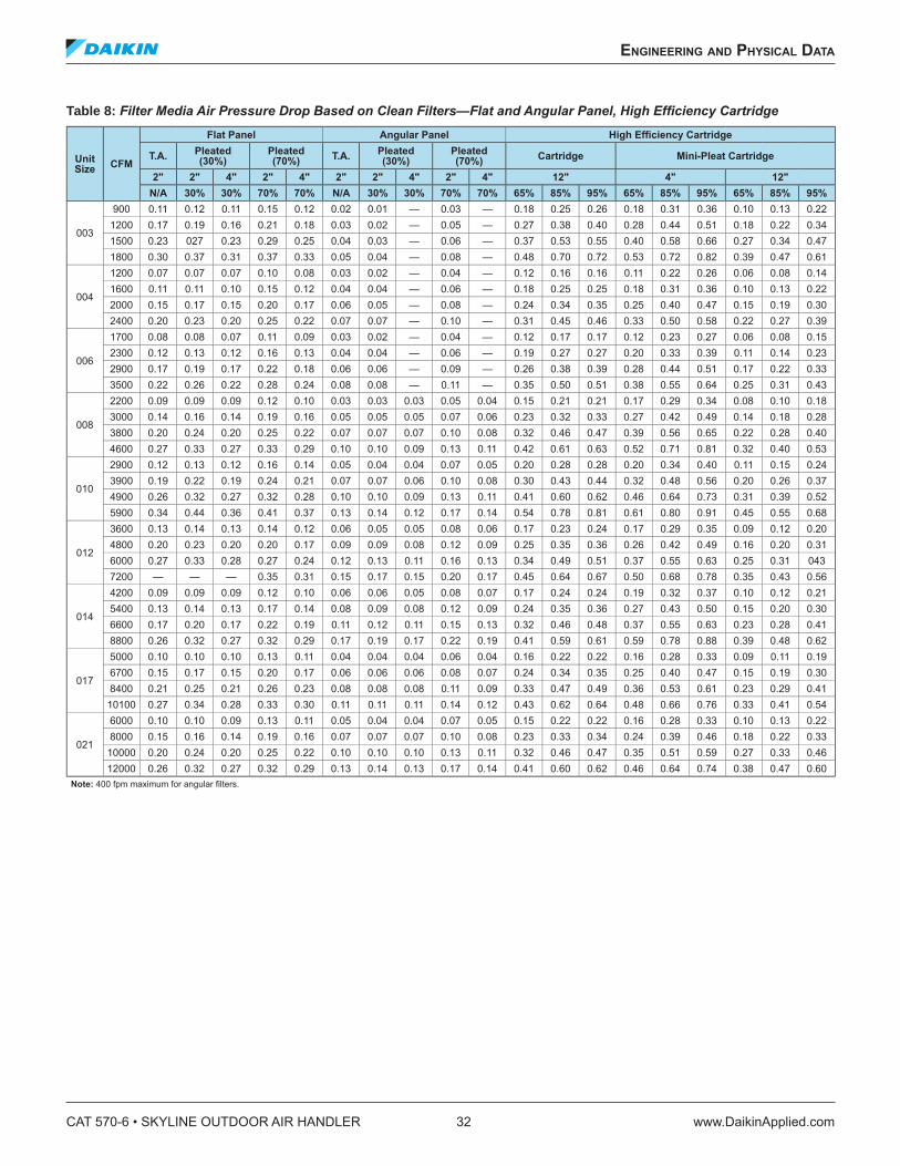
Table 8: Filter Media Air Pressure Drop Based on Clean Filters—Flat and Angular Panel, High Eficiency Cartridge
Unit Size
CFM
Flat Panel Angular Panel High Eficiency Cartridge
T.A.Pleated (30%)
Pleated (70%) T.A.
Pleated (30%)
Pleated (70%) Cartridge Mini-Pleat Cartridge
2" 2" 4" 2" 4" 2" 2" 4" 2" 4" 12" 4" 12"
N/A 30% 30% 70% 70% N/A 30% 30% 70% 70% 65% 85% 95% 65% 85% 95% 65% 85% 95%
003
900 0.11 0.12 0.11 0.15 0.12 0.02 0.01 — 0.03 — 0.18 0.25 0.26 0.18 0.31 0.36 0.10 0.13 0.22
1200 0.17 0.19 0.16 0.21 0.18 0.03 0.02 — 0.05 — 0.27 0.38 0.40 0.28 0.44 0.51 0.18 0.22 0.34
1500 0.23 027 0.23 0.29 0.25 0.04 0.03 — 0.06 — 0.37 0.53 0.55 0.40 0.58 0.66 0.27 0.34 0.47
1800 0.30 0.37 0.31 0.37 0.33 0.05 0.04 — 0.08 — 0.48 0.70 0.72 0.53 0.72 0.82 0.39 0.47 0.61
004
1200 0.07 0.07 0.07 0.10 0.08 0.03 0.02 — 0.04 — 0.12 0.16 0.16 0.11 0.22 0.26 0.06 0.08 0.14
1600 0.11 0.11 0.10 0.15 0.12 0.04 0.04 — 0.06 — 0.18 0.25 0.25 0.18 0.31 0.36 0.10 0.13 0.22
2000 0.15 0.17 0.15 0.20 0.17 0.06 0.05 — 0.08 — 0.24 0.34 0.35 0.25 0.40 0.47 0.15 0.19 0.30
2400 0.20 0.23 0.20 0.25 0.22 0.07 0.07 — 0.10 — 0.31 0.45 0.46 0.33 0.50 0.58 0.22 0.27 0.39
006
1700 0.08 0.08 0.07 0.11 0.09 0.03 0.02 — 0.04 — 0.12 0.17 0.17 0.12 0.23 0.27 0.06 0.08 0.15
2300 0.12 0.13 0.12 0.16 0.13 0.04 0.04 — 0.06 — 0.19 0.27 0.27 0.20 0.33 0.39 0.11 0.14 0.23
2900 0.17 0.19 0.17 0.22 0.18 0.06 0.06 — 0.09 — 0.26 0.38 0.39 0.28 0.44 0.51 0.17 0.22 0.33
3500 0.22 0.26 0.22 0.28 0.24 0.08 0.08 — 0.11 — 0.35 0.50 0.51 0.38 0.55 0.64 0.25 0.31 0.43
008
2200 0.09 0.09 0.09 0.12 0.10 0.03 0.03 0.03 0.05 0.04 0.15 0.21 0.21 0.17 0.29 0.34 0.08 0.10 0.18
3000 0.14 0.16 0.14 0.19 0.16 0.05 0.05 0.05 0.07 0.06 0.23 0.32 0.33 0.27 0.42 0.49 0.14 0.18 0.28
3800 0.20 0.24 0.20 0.25 0.22 0.07 0.07 0.07 0.10 0.08 0.32 0.46 0.47 0.39 0.56 0.65 0.22 0.28 0.40
4600 0.27 0.33 0.27 0.33 0.29 0.10 0.10 0.09 0.13 0.11 0.42 0.61 0.63 0.52 0.71 0.81 0.32 0.40 0.53
010
2900 0.12 0.13 0.12 0.16 0.14 0.05 0.04 0.04 0.07 0.05 0.20 0.28 0.28 0.20 0.34 0.40 0.11 0.15 0.24
3900 0.19 0.22 0.19 0.24 0.21 0.07 0.07 0.06 0.10 0.08 0.30 0.43 0.44 0.32 0.48 0.56 0.20 0.26 0.37
4900 0.26 0.32 0.27 0.32 0.28 0.10 0.10 0.09 0.13 0.11 0.41 0.60 0.62 0.46 0.64 0.73 0.31 0.39 0.52
5900 0.34 0.44 0.36 0.41 0.37 0.13 0.14 0.12 0.17 0.14 0.54 0.78 0.81 0.61 0.80 0.91 0.45 0.55 0.68
012
3600 0.13 0.14 0.13 0.14 0.12 0.06 0.05 0.05 0.08 0.06 0.17 0.23 0.24 0.17 0.29 0.35 0.09 0.12 0.20
4800 0.20 0.23 0.20 0.20 0.17 0.09 0.09 0.08 0.12 0.09 0.25 0.35 0.36 0.26 0.42 0.49 0.16 0.20 0.31
6000 0.27 0.33 0.28 0.27 0.24 0.12 0.13 0.11 0.16 0.13 0.34 0.49 0.51 0.37 0.55 0.63 0.25 0.31 043
7200 — — — 0.35 0.31 0.15 0.17 0.15 0.20 0.17 0.45 0.64 0.67 0.50 0.68 0.78 0.35 0.43 0.56
014
4200 0.09 0.09 0.09 0.12 0.10 0.06 0.06 0.05 0.08 0.07 0.17 0.24 0.24 0.19 0.32 0.37 0.10 0.12 0.21
5400 0.13 0.14 0.13 0.17 0.14 0.08 0.09 0.08 0.12 0.09 0.24 0.35 0.36 0.27 0.43 0.50 0.15 0.20 0.30
6600 0.17 0.20 0.17 0.22 0.19 0.11 0.12 0.11 0.15 0.13 0.32 0.46 0.48 0.37 0.55 0.63 0.23 0.28 0.41
8800 0.26 0.32 0.27 0.32 0.29 0.17 0.19 0.17 0.22 0.19 0.41 0.59 0.61 0.59 0.78 0.88 0.39 0.48 0.62
017
5000 0.10 0.10 0.10 0.13 0.11 0.04 0.04 0.04 0.06 0.04 0.16 0.22 0.22 0.16 0.28 0.33 0.09 0.11 0.19
6700 0.15 0.17 0.15 0.20 0.17 0.06 0.06 0.06 0.08 0.07 0.24 0.34 0.35 0.25 0.40 0.47 0.15 0.19 0.30
8400 0.21 0.25 0.21 0.26 0.23 0.08 0.08 0.08 0.11 0.09 0.33 0.47 0.49 0.36 0.53 0.61 0.23 0.29 0.41
10100 0.27 0.34 0.28 0.33 0.30 0.11 0.11 0.11 0.14 0.12 0.43 0.62 0.64 0.48 0.66 0.76 0.33 0.41 0.54
021
6000 0.10 0.10 0.09 0.13 0.11 0.05 0.04 0.04 0.07 0.05 0.15 0.22 0.22 0.16 0.28 0.33 0.10 0.13 0.22
8000 0.15 0.16 0.14 0.19 0.16 0.07 0.07 0.07 0.10 0.08 0.23 0.33 0.34 0.24 0.39 0.46 0.18 0.22 0.33
10000 0.20 0.24 0.20 0.25 0.22 0.10 0.10 0.10 0.13 0.11 0.32 0.46 0.47 0.35 0.51 0.59 0.27 0.33 0.46
12000 0.26 0.32 0.27 0.32 0.29 0.13 0.14 0.13 0.17 0.14 0.41 0.60 0.62 0.46 0.64 0.74 0.38 0.47 0.60
Note: 400 fpm maximum for angular ilters.
CAT 570-6 • SKYLINE OUTDOOR AIR HANDLER 32 www.DaikinApplied.com
engineering and physiCal daTa
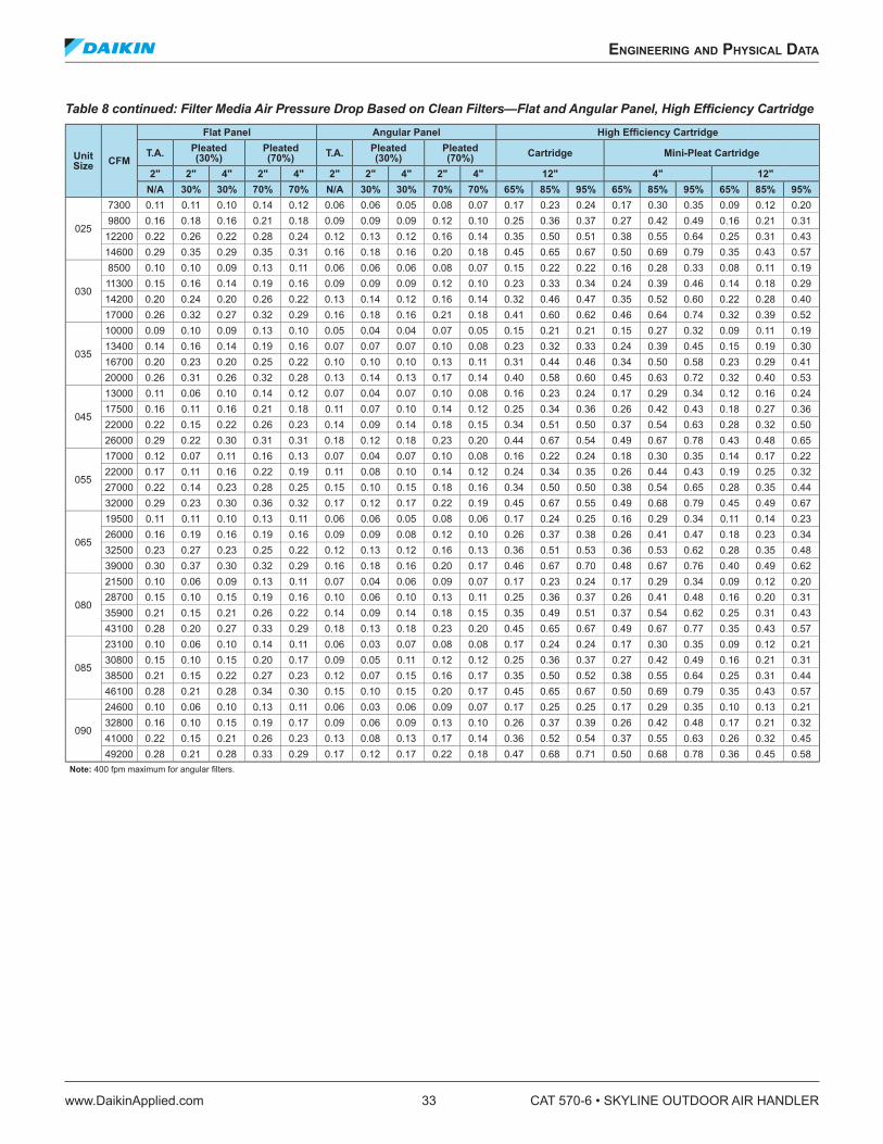
Table 8 continued: Filter Media Air Pressure Drop Based on Clean Filters—Flat and Angular Panel, High Eficiency Cartridge
Unit Size
CFM
Flat Panel Angular Panel High Eficiency Cartridge
T.A.Pleated (30%)
Pleated (70%) T.A.
Pleated (30%)
Pleated (70%) Cartridge Mini-Pleat Cartridge
2" 2" 4" 2" 4" 2" 2" 4" 2" 4" 12" 4" 12"
N/A 30% 30% 70% 70% N/A 30% 30% 70% 70% 65% 85% 95% 65% 85% 95% 65% 85% 95%
025
7300 0.11 0.11 0.10 0.14 0.12 0.06 0.06 0.05 0.08 0.07 0.17 0.23 0.24 0.17 0.30 0.35 0.09 0.12 0.20
9800 0.16 0.18 0.16 0.21 0.18 0.09 0.09 0.09 0.12 0.10 0.25 0.36 0.37 0.27 0.42 0.49 0.16 0.21 0.31
12200 0.22 0.26 0.22 0.28 0.24 0.12 0.13 0.12 0.16 0.14 0.35 0.50 0.51 0.38 0.55 0.64 0.25 0.31 0.43
14600 0.29 0.35 0.29 0.35 0.31 0.16 0.18 0.16 0.20 0.18 0.45 0.65 0.67 0.50 0.69 0.79 0.35 0.43 0.57
030
8500 0.10 0.10 0.09 0.13 0.11 0.06 0.06 0.06 0.08 0.07 0.15 0.22 0.22 0.16 0.28 0.33 0.08 0.11 0.19
11300 0.15 0.16 0.14 0.19 0.16 0.09 0.09 0.09 0.12 0.10 0.23 0.33 0.34 0.24 0.39 0.46 0.14 0.18 0.29
14200 0.20 0.24 0.20 0.26 0.22 0.13 0.14 0.12 0.16 0.14 0.32 0.46 0.47 0.35 0.52 0.60 0.22 0.28 0.40
17000 0.26 0.32 0.27 0.32 0.29 0.16 0.18 0.16 0.21 0.18 0.41 0.60 0.62 0.46 0.64 0.74 0.32 0.39 0.52
035
10000 0.09 0.10 0.09 0.13 0.10 0.05 0.04 0.04 0.07 0.05 0.15 0.21 0.21 0.15 0.27 0.32 0.09 0.11 0.19
13400 0.14 0.16 0.14 0.19 0.16 0.07 0.07 0.07 0.10 0.08 0.23 0.32 0.33 0.24 0.39 0.45 0.15 0.19 0.30
16700 0.20 0.23 0.20 0.25 0.22 0.10 0.10 0.10 0.13 0.11 0.31 0.44 0.46 0.34 0.50 0.58 0.23 0.29 0.41
20000 0.26 0.31 0.26 0.32 0.28 0.13 0.14 0.13 0.17 0.14 0.40 0.58 0.60 0.45 0.63 0.72 0.32 0.40 0.53
045
13000 0.11 0.06 0.10 0.14 0.12 0.07 0.04 0.07 0.10 0.08 0.16 0.23 0.24 0.17 0.29 0.34 0.12 0.16 0.24
17500 0.16 0.11 0.16 0.21 0.18 0.11 0.07 0.10 0.14 0.12 0.25 0.34 0.36 0.26 0.42 0.43 0.18 0.27 0.36
22000 0.22 0.15 0.22 0.26 0.23 0.14 0.09 0.14 0.18 0.15 0.34 0.51 0.50 0.37 0.54 0.63 0.28 0.32 0.50
26000 0.29 0.22 0.30 0.31 0.31 0.18 0.12 0.18 0.23 0.20 0.44 0.67 0.54 0.49 0.67 0.78 0.43 0.48 0.65
055
17000 0.12 0.07 0.11 0.16 0.13 0.07 0.04 0.07 0.10 0.08 0.16 0.22 0.24 0.18 0.30 0.35 0.14 0.17 0.22
22000 0.17 0.11 0.16 0.22 0.19 0.11 0.08 0.10 0.14 0.12 0.24 0.34 0.35 0.26 0.44 0.43 0.19 0.25 0.32
27000 0.22 0.14 0.23 0.28 0.25 0.15 0.10 0.15 0.18 0.16 0.34 0.50 0.50 0.38 0.54 0.65 0.28 0.35 0.44
32000 0.29 0.23 0.30 0.36 0.32 0.17 0.12 0.17 0.22 0.19 0.45 0.67 0.55 0.49 0.68 0.79 0.45 0.49 0.67
065
19500 0.11 0.11 0.10 0.13 0.11 0.06 0.06 0.05 0.08 0.06 0.17 0.24 0.25 0.16 0.29 0.34 0.11 0.14 0.23
26000 0.16 0.19 0.16 0.19 0.16 0.09 0.09 0.08 0.12 0.10 0.26 0.37 0.38 0.26 0.41 0.47 0.18 0.23 0.34
32500 0.23 0.27 0.23 0.25 0.22 0.12 0.13 0.12 0.16 0.13 0.36 0.51 0.53 0.36 0.53 0.62 0.28 0.35 0.48
39000 0.30 0.37 0.30 0.32 0.29 0.16 0.18 0.16 0.20 0.17 0.46 0.67 0.70 0.48 0.67 0.76 0.40 0.49 0.62
080
21500 0.10 0.06 0.09 0.13 0.11 0.07 0.04 0.06 0.09 0.07 0.17 0.23 0.24 0.17 0.29 0.34 0.09 0.12 0.20
28700 0.15 0.10 0.15 0.19 0.16 0.10 0.06 0.10 0.13 0.11 0.25 0.36 0.37 0.26 0.41 0.48 0.16 0.20 0.31
35900 0.21 0.15 0.21 0.26 0.22 0.14 0.09 0.14 0.18 0.15 0.35 0.49 0.51 0.37 0.54 0.62 0.25 0.31 0.43
43100 0.28 0.20 0.27 0.33 0.29 0.18 0.13 0.18 0.23 0.20 0.45 0.65 0.67 0.49 0.67 0.77 0.35 0.43 0.57
085
23100 0.10 0.06 0.10 0.14 0.11 0.06 0.03 0.07 0.08 0.08 0.17 0.24 0.24 0.17 0.30 0.35 0.09 0.12 0.21
30800 0.15 0.10 0.15 0.20 0.17 0.09 0.05 0.11 0.12 0.12 0.25 0.36 0.37 0.27 0.42 0.49 0.16 0.21 0.31
38500 0.21 0.15 0.22 0.27 0.23 0.12 0.07 0.15 0.16 0.17 0.35 0.50 0.52 0.38 0.55 0.64 0.25 0.31 0.44
46100 0.28 0.21 0.28 0.34 0.30 0.15 0.10 0.15 0.20 0.17 0.45 0.65 0.67 0.50 0.69 0.79 0.35 0.43 0.57
090
24600 0.10 0.06 0.10 0.13 0.11 0.06 0.03 0.06 0.09 0.07 0.17 0.25 0.25 0.17 0.29 0.35 0.10 0.13 0.21
32800 0.16 0.10 0.15 0.19 0.17 0.09 0.06 0.09 0.13 0.10 0.26 0.37 0.39 0.26 0.42 0.48 0.17 0.21 0.32
41000 0.22 0.15 0.21 0.26 0.23 0.13 0.08 0.13 0.17 0.14 0.36 0.52 0.54 0.37 0.55 0.63 0.26 0.32 0.45
49200 0.28 0.21 0.28 0.33 0.29 0.17 0.12 0.17 0.22 0.18 0.47 0.68 0.71 0.50 0.68 0.78 0.36 0.45 0.58
Note: 400 fpm maximum for angular ilters.
engineering and physiCal daTa
www.DaikinApplied.com 33 CAT 570-6 • SKYLINE OUTDOOR AIR HANDLER
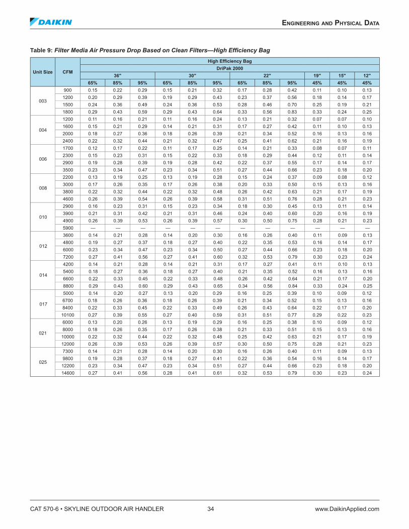
Table 9: Filter Media Air Pressure Drop Based on Clean Filters—High Eficiency Bag
Unit Size CFM
High Eficiency BagDriPak 2000
36" 30" 22" 19" 15" 12"
65% 85% 95% 65% 85% 95% 65% 85% 95% 45% 45% 45%
003
900 0.15 0.22 0.29 0.15 0.21 0.32 0.17 0.28 0.42 0.11 0.10 0.13
1200 0.20 0.29 0.39 0.19 0.29 0.43 0.23 0.37 0.56 0.18 0.14 0.17
1500 0.24 0.36 0.49 0.24 0.36 0.53 0.28 0.46 0.70 0.25 0.19 0.21
1800 0.29 0.43 0.59 0.29 0.43 0.64 0.33 0.56 0.83 0.33 0.24 0.25
004
1200 0.11 0.16 0.21 0.11 0.16 0.24 0.13 0.21 0.32 0.07 0.07 0.10
1600 0.15 0.21 0.29 0.14 0.21 0.31 0.17 0.27 0.42 0.11 0.10 0.13
2000 0.18 0.27 0.36 0.18 0.26 0.39 0.21 0.34 0.52 0.16 0.13 0.16
2400 0.22 0.32 0.44 0.21 0.32 0.47 0.25 0.41 0.62 0.21 0.16 0.19
006
1700 0.12 0.17 0.22 0.11 0.17 0.25 0.14 0.21 0.33 0.08 0.07 0.11
2300 0.15 0.23 0.31 0.15 0.22 0.33 0.18 0.29 0.44 0.12 0.11 0.14
2900 0.19 0.28 0.39 0.19 0.28 0.42 0.22 0.37 0.55 0.17 0.14 0.17
3500 0.23 0.34 0.47 0.23 0.34 0.51 0.27 0.44 0.66 0.23 0.18 0.20
008
2200 0.13 0.19 0.25 0.13 0.19 0.28 0.15 0.24 0.37 0.09 0.08 0.12
3000 0.17 0.26 0.35 0.17 0.26 0.38 0.20 0.33 0.50 0.15 0.13 0.16
3800 0.22 0.32 0.44 0.22 0.32 0.48 0.26 0.42 0.63 0.21 0.17 0.19
4600 0.26 0.39 0.54 0.26 0.39 0.58 0.31 0.51 0.76 0.28 0.21 0.23
010
2900 0.16 0.23 0.31 0.15 0.23 0.34 0.18 0.30 0.45 0.13 0.11 0.14
3900 0.21 0.31 0.42 0.21 0.31 0.46 0.24 0.40 0.60 0.20 0.16 0.19
4900 0.26 0.39 0.53 0.26 0.39 0.57 0.30 0.50 0.75 0.28 0.21 0.23
5900 — — — — — — — — — — — —
012
3600 0.14 0.21 0.28 0.14 0.20 0.30 0.16 0.26 0.40 0.11 0.09 0.13
4800 0.19 0.27 0.37 0.18 0.27 0.40 0.22 0.35 0.53 0.16 0.14 0.17
6000 0.23 0.34 0.47 0.23 0.34 0.50 0.27 0.44 0.66 0.23 0.18 0.20
7200 0.27 0.41 0.56 0.27 0.41 0.60 0.32 0.53 0.79 0.30 0.23 0.24
014
4200 0.14 0.21 0.28 0.14 0.21 0.31 0.17 0.27 0.41 0.11 0.10 0.13
5400 0.18 0.27 0.36 0.18 0.27 0.40 0.21 0.35 0.52 0.16 0.13 0.16
6600 0.22 0.33 0.45 0.22 0.33 0.48 0.26 0.42 0.64 0.21 0.17 0.20
8800 0.29 0.43 0.60 0.29 0.43 0.65 0.34 0.56 0.84 0.33 0.24 0.25
017
5000 0.14 0.20 0.27 0.13 0.20 0.29 0.16 0.25 0.39 0.10 0.09 0.12
6700 0.18 0.26 0.36 0.18 0.26 0.39 0.21 0.34 0.52 0.15 0.13 0.16
8400 0.22 0.33 0.45 0.22 0.33 0.49 0.26 0.43 0.64 0.22 0.17 0.20
10100 0.27 0.39 0.55 0.27 0.40 0.59 0.31 0.51 0.77 0.29 0.22 0.23
021
6000 0.13 0.20 0.26 0.13 0.19 0.29 0.16 0.25 0.38 0.10 0.09 0.12
8000 0.18 0.26 0.35 0.17 0.26 0.38 0.21 0.33 0.51 0.15 0.13 0.16
10000 0.22 0.32 0.44 0.22 0.32 0.48 0.25 0.42 0.63 0.21 0.17 0.19
12000 0.26 0.39 0.53 0.26 0.39 0.57 0.30 0.50 0.75 0.28 0.21 0.23
025
7300 0.14 0.21 0.28 0.14 0.20 0.30 0.16 0.26 0.40 0.11 0.09 0.13
9800 0.19 0.28 0.37 0.18 0.27 0.41 0.22 0.36 0.54 0.16 0.14 0.17
12200 0.23 0.34 0.47 0.23 0.34 0.51 0.27 0.44 0.66 0.23 0.18 0.20
14600 0.27 0.41 0.56 0.28 0.41 0.61 0.32 0.53 0.79 0.30 0.23 0.24
CAT 570-6 • SKYLINE OUTDOOR AIR HANDLER 34 www.DaikinApplied.com
engineering and physiCal daTa
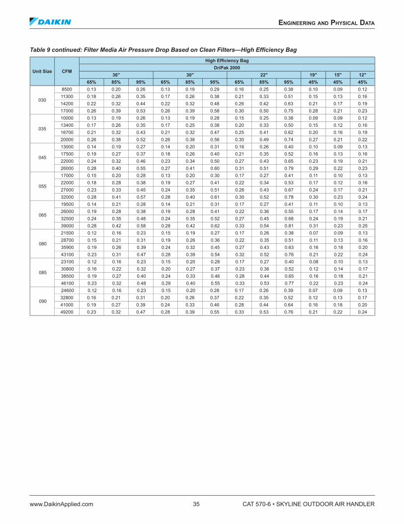
Table 9 continued: Filter Media Air Pressure Drop Based on Clean Filters—High Eficiency Bag
Unit Size CFM
High Eficiency BagDriPak 2000
36" 30" 22" 19" 15" 12"
65% 85% 95% 65% 85% 95% 65% 85% 95% 45% 45% 45%
030
8500 0.13 0.20 0.26 0.13 0.19 0.29 0.16 0.25 0.38 0.10 0.09 0.12
11300 0.18 0.26 0.35 0.17 0.26 0.38 0.21 0.33 0.51 0.15 0.13 0.16
14200 0.22 0.32 0.44 0.22 0.32 0.48 0.26 0.42 0.63 0.21 0.17 0.19
17000 0.26 0.39 0.53 0.26 0.39 0.58 0.30 0.50 0.75 0.28 0.21 0.23
035
10000 0.13 0.19 0.26 0.13 0.19 0.28 0.15 0.25 0.38 0.09 0.09 0.12
13400 0.17 0.26 0.35 0.17 0.25 0.38 0.20 0.33 0.50 0.15 0.12 0.16
16700 0.21 0.32 0.43 0.21 0.32 0.47 0.25 0.41 0.62 0.20 0.16 0.19
20000 0.26 0.38 0.52 0.26 0.38 0.56 0.30 0.49 0.74 0.27 0.21 0.22
045
13000 0.14 0.19 0.27 0.14 0.20 0.31 0.16 0.26 0.40 0.10 0.09 0.13
17500 0.19 0.27 0.37 0.18 0.26 0.40 0.21 0.35 0.52 0.16 0.13 0.16
22000 0.24 0.32 0.46 0.23 0.34 0.50 0.27 0.43 0.65 0.23 0.19 0.21
26000 0.28 0.40 0.55 0.27 0.41 0.60 0.31 0.51 0.79 0.29 0.22 0.23
055
17000 0.15 0.20 0.28 0.13 0.20 0.30 0.17 0.27 0.41 0.11 0.10 0.13
22000 0.18 0.28 0.38 0.19 0.27 0.41 0.22 0.34 0.53 0.17 0.12 0.16
27000 0.23 0.33 0.45 0.24 0.35 0.51 0.26 0.43 0.67 0.24 0.17 0.21
32000 0.28 0.41 0.57 0.28 0.40 0.61 0.30 0.52 0.78 0.30 0.23 0.24
065
19500 0.14 0.21 0.28 0.14 0.21 0.31 0.17 0.27 0.41 0.11 0.10 0.13
26000 0.19 0.28 0.38 0.19 0.28 0.41 0.22 0.36 0.55 0.17 0.14 0.17
32500 0.24 0.35 0.48 0.24 0.35 0.52 0.27 0.45 0.68 0.24 0.19 0.21
39000 0.28 0.42 0.58 0.28 0.42 0.62 0.33 0.54 0.81 0.31 0.23 0.25
080
21500 0.12 0.16 0.23 0.15 0.19 0.27 0.17 0.26 0.38 0.07 0.09 0.13
28700 0.15 0.21 0.31 0.19 0.26 0.36 0.22 0.35 0.51 0.11 0.13 0.16
35900 0.19 0.26 0.39 0.24 0.32 0.45 0.27 0.43 0.63 0.16 0.18 0.20
43100 0.23 0.31 0.47 0.28 0.39 0.54 0.32 0.52 0.76 0.21 0.22 0.24
085
23100 0.12 0.16 0.23 0.15 0.20 0.28 0.17 0.27 0.40 0.08 0.10 0.13
30800 0.16 0.22 0.32 0.20 0.27 0.37 0.23 0.36 0.52 0.12 0.14 0.17
38500 0.19 0.27 0.40 0.24 0.33 0.46 0.28 0.44 0.65 0.16 0.18 0.21
46100 0.23 0.32 0.48 0.29 0.40 0.55 0.33 0.53 0.77 0.22 0.23 0.24
090
24600 0.12 0.16 0.23 0.15 0.20 0.28 0.17 0.26 0.39 0.07 0.09 0.13
32800 0.16 0.21 0.31 0.20 0.26 0.37 0.22 0.35 0.52 0.12 0.13 0.17
41000 0.19 0.27 0.39 0.24 0.33 0.46 0.28 0.44 0.64 0.16 0.18 0.20
49200 0.23 0.32 0.47 0.28 0.39 0.55 0.33 0.53 0.76 0.21 0.22 0.24
engineering and physiCal daTa
www.DaikinApplied.com 35 CAT 570-6 • SKYLINE OUTDOOR AIR HANDLER
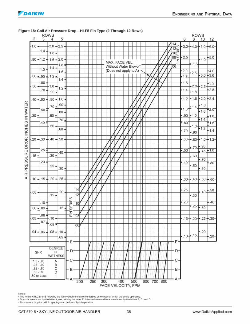
Figure 18: Coil Air Pressure Drop—HI-F5 Fin Type (2 Through 12 Rows)
Notes: • The letters A,B,C,D or E following the face velocity indicate the degree of wetness at which the coil is operating. • Dry coils are shown by the letter A, wet coils by the letter E. Intermediate conditions are shown by the letters B, C, and D. • Air pressure drop for odd in spacings can be found by interpolation.
CAT 570-6 • SKYLINE OUTDOOR AIR HANDLER 36 www.DaikinApplied.com
engineering and physiCal daTa
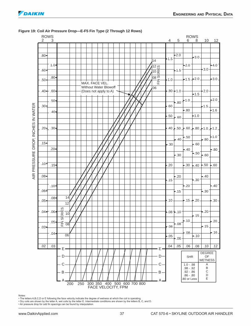
Figure 19: Coil Air Pressure Drop—E-F5 Fin Type (2 Through 12 Rows)
Notes: • The letters A,B,C,D or E following the face velocity indicate the degree of wetness at which the coil is operating. • Dry coils are shown by the letter A, wet coils by the letter E. Intermediate conditions are shown by the letters B, C, and D. • Air pressure drop for odd in spacings can be found by interpolation.
2 3ROWS
14
12
10
08
06
2.0
E
D
C
B
A
FACE VELOCITY, FPM200 250 300 400 500 600 700 800
AIR
PR
ES
SU
RE
DR
OP,
INC
HE
S IN
WA
TE
R
FIN
SE
RIE
S
SHRDEGREE
OFWETNESS
1.0 - .98.98 - .92.92 - .86.86 - .80
.80 or Less
ABCDE
MAX. FACE VEL.Without Water Blowoff(Does not apply to A)
E
D
C
B
A350
4 5 6 8 10 12ROWS
14
12
10
08
06
FIN
SE
RIE
S
1.5 3.0
2.0 4.0
1.5 3.0
1.0 1.5 2.0 3.0
.80 1.0 2.01.5
2.01.0.80
.60.80
1.51.6
.50 1.0.60
.40 .50 .60 .80 1.0 1.2
.50 1.0.40 .80
.30 .60
.40 .80
.30 .60.50
.20 .30 .40 .50 .60
.20 .40.15 .30
.20 .40
.15 .30
.10 .15 .20 .30
.08 .10 .20.15
.10 .20.08
.06 .15
.08 .16.05
.06.10
.05.04 .06 .08 .10 .12
.80
1.0
.60
.80.50
.40 .60
.50
.30
.40
.20 .30
.15
.20
.15.10
.08
.10.06
.08.05
.04 .06
.05
.04
.03
.03.02
engineering and physiCal daTa
www.DaikinApplied.com 37 CAT 570-6 • SKYLINE OUTDOOR AIR HANDLER
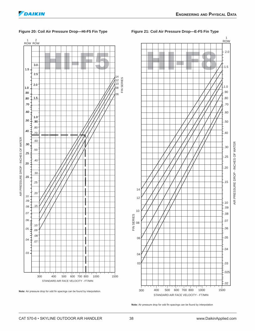
Figure 20: Coil Air Pressure Drop—HI-F5 Fin Type
Note: Air pressure drop for odd in spacings can be found by interpolation.
Figure 21: Coil Air Pressure Drop—E-F5 Fin Type
Note: Air pressure drop for odd in spacings can be found by interpolation
HI-F5
300
.07
.15
.20
.25
.30
.60
1.51.5
3.03.0
1ROW
2ROW
.10
400 500 600 700 800 1000 1500
STANDARD AIR FACE VELOCITY - FT/MIN
AIR
PR
ES
SU
RE
DR
OP
- IN
CH
ES
OF
WA
TE
R
2.52.5
2.02.0
.90.90
1.01.0
.80
.40
.09
.08
.50
.03
.04
.05
.06
.07
.08
.09
.10
.15.15
.20.20
.25.25
.30.30
.40.40
.50.50
.60.60
.70.70
.80.80
.90.90
1.01.0
1.51.5
14
06
08
1012
FIN
SE
RIE
S
.70
HI-F8
300 400 500 600 700 800 1000 1500
STANDARD AIR FACE VELOCITY - FT/MIN
1ROW
AIR
PR
ES
SU
RE
DR
OP
- IN
CH
ES
OF
WA
TE
R
.03
.025
.02
.04
.05
.06
.07
.08
.09
.10
.15
.20
.25
.30
.40
.50
.60
.70
.80
.90
1.0
1.5
2.0
03
04
06
08
10
12
14
FIN
SE
RIE
S
CAT 570-6 • SKYLINE OUTDOOR AIR HANDLER 38 www.DaikinApplied.com
engineering and physiCal daTa
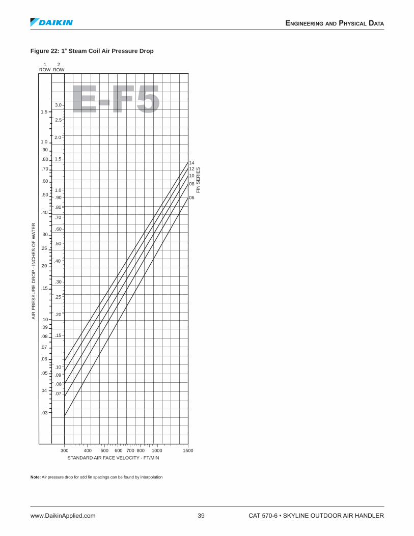
Figure 22: 1 " Steam Coil Air Pressure Drop
Note: Air pressure drop for odd in spacings can be found by interpolation
E-F5
300
.07
.15
.20
.25
.30
.60
.70
1.5
3.0
1ROW
2ROW
.10
400 500 600 700 800 1000 1500
STANDARD AIR FACE VELOCITY - FT/MIN
AIR
PR
ES
SU
RE
DR
OP
- IN
CH
ES
OF
WA
TE
R
2.5
2.0
.90
1.0
.80
.40
.09
.08
.50
14
06
08
10
12
FIN
SE
RIE
S
.20
.25
.30
.40
.50
.60
.70
.80
.90
1.0
1.5
.10
.09
.08
.07
.06
.05
.04
.03
.15
engineering and physiCal daTa
www.DaikinApplied.com 39 CAT 570-6 • SKYLINE OUTDOOR AIR HANDLER
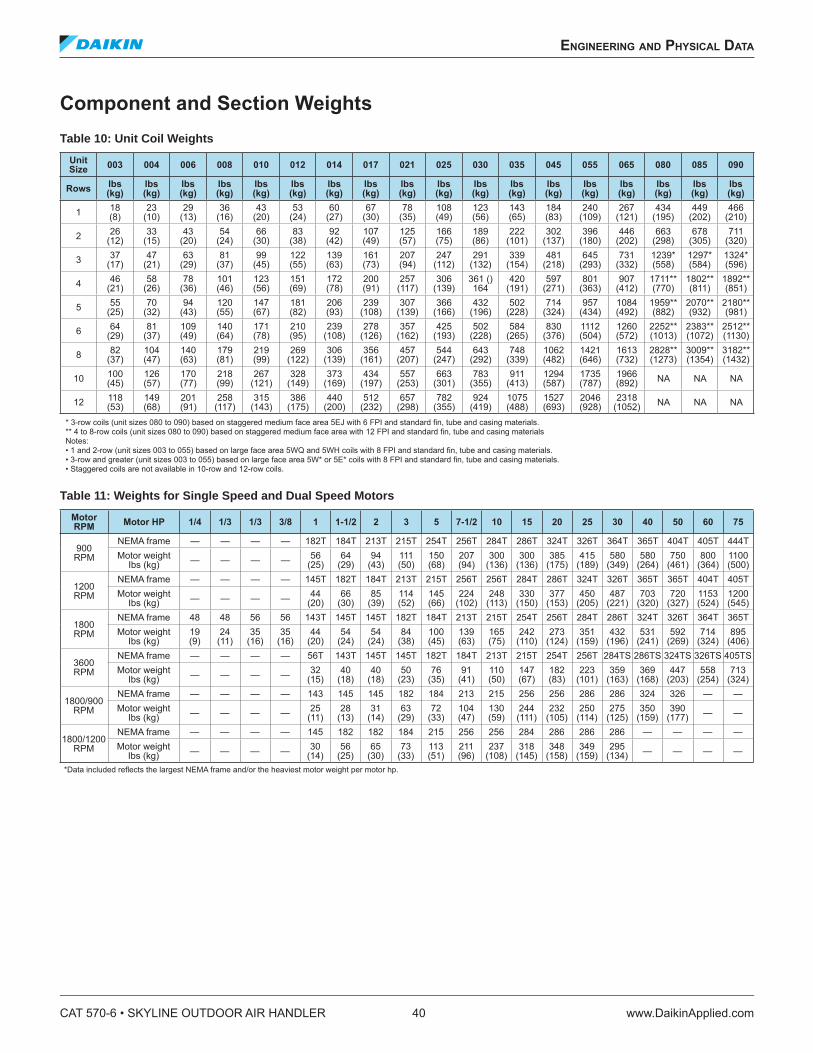
Component and Section Weights
Table 10: Unit Coil Weights
Unit Size
003 004 006 008 010 012 014 017 021 025 030 035 045 055 065 080 085 090
Rowslbs (kg)
lbs (kg)
lbs (kg)
lbs (kg)
lbs (kg)
lbs (kg)
lbs (kg)
lbs (kg)
lbs (kg)
lbs (kg)
lbs (kg)
lbs (kg)
lbs (kg)
lbs (kg)
lbs (kg)
lbs (kg)
lbs (kg)
lbs (kg)
118 (8)
23 (10)
29 (13)
36 (16)
43 (20)
53 (24)
60 (27)
67 (30)
78 (35)
108 (49)
123 (56)
143 (65)
184 (83)
240 (109)
267 (121)
434 (195)
449 (202)
466 (210)
226
(12)33
(15)43
(20) 54
(24)66
(30)83
(38)92
(42) 107 (49)
125 (57)
166 (75)
189 (86)
222 (101)
302 (137)
396 (180)
446 (202)
663 (298)
678 (305)
711 (320)
337
(17)47
(21)63
(29)81
(37)99
(45)122 (55)
139 (63)
161 (73)
207 (94)
247 (112)
291 (132)
339 (154)
481 (218)
645 (293)
731 (332)
1239* (558)
1297* (584)
1324* (596)
446
(21)58
(26)78
(36)101 (46)
123 (56)
151 (69)
172 (78)
200 (91)
257 (117)
306 (139)
361 () 164
420 (191)
597 (271)
801 (363)
907 (412)
1711** (770)
1802** (811)
1892** (851)
555
(25)70
(32)94
(43)120 (55)
147 (67)
181 (82)
206 (93)
239 (108)
307 (139)
366 (166)
432 (196)
502 (228)
714 (324)
957 (434)
1084 (492)
1959** (882)
2070** (932)
2180** (981)
664
(29) 81
(37)109 (49)
140 (64)
171 (78)
210 (95)
239 (108)
278 (126)
357 (162)
425 (193)
502 (228)
584 (265)
830 (376)
1112 (504)
1260 (572)
2252** (1013)
2383** (1072)
2512** (1130)
882
(37)104 (47)
140 (63)
179 (81)
219 (99)
269 (122)
306 (139)
356 (161)
457 (207)
544 (247)
643 (292)
748 (339)
1062 (482)
1421 (646)
1613 (732)
2828** (1273)
3009** (1354)
3182** (1432)
10100 (45)
126 (57)
170 (77)
218 (99)
267 (121)
328 (149)
373 (169)
434 (197)
557 (253)
663 (301)
783 (355)
911 (413)
1294 (587)
1735 (787)
1966 (892) NA NA NA
12118 (53)
149 (68)
201 (91)
258 (117)
315 (143)
386 (175)
440 (200)
512 (232)
657 (298)
782 (355)
924 (419)
1075 (488)
1527 (693)
2046 (928)
2318 (1052) NA NA NA
* 3-row coils (unit sizes 080 to 090) based on staggered medium face area 5EJ with 6 FPI and standard in, tube and casing materials. ** 4 to 8-row coils (unit sizes 080 to 090) based on staggered medium face area with 12 FPI and standard in, tube and casing materials Notes: • 1 and 2-row (unit sizes 003 to 055) based on large face area 5WQ and 5WH coils with 8 FPI and standard in, tube and casing materials. • 3-row and greater (unit sizes 003 to 055) based on large face area 5W* or 5E* coils with 8 FPI and standard in, tube and casing materials. • Staggered coils are not available in 10-row and 12-row coils.
Table 11: Weights for Single Speed and Dual Speed Motors
Motor RPM
Motor HP 1/4 1/3 1/3 3/8 1 1-1/2 2 3 5 7-1/2 10 15 20 25 30 40 50 60 75
900 RPM
NEMA frame — — — — 182T 184T 213T 215T 254T 256T 284T 286T 324T 326T 364T 365T 404T 405T 444TMotor weight
Ibs (kg) — — — — 56 (25)
64 (29)
94 (43)
111 (50)
150 (68)
207 (94)
300 (136)
300 (136)
385 (175)
415 (189)
580 (349)
580 (264)
750 (461)
800 (364)
1100 (500)
1200 RPM
NEMA frame — — — — 145T 182T 184T 213T 215T 256T 256T 284T 286T 324T 326T 365T 365T 404T 405TMotor weight
Ibs (kg) — — — — 44 (20)
66 (30)
85 (39)
114 (52)
145 (66)
224 (102)
248 (113)
330 (150)
377 (153)
450 (205)
487 (221)
703 (320)
720 (327)
1153 (524)
1200 (545)
1800 RPM
NEMA frame 48 48 56 56 143T 145T 145T 182T 184T 213T 215T 254T 256T 284T 286T 324T 326T 364T 365TMotor weight
Ibs (kg)19 (9)
24 (11)
35 (16)
35 (16)
44 (20)
54 (24)
54 (24)
84 (38)
100 (45)
139 (63)
165 (75)
242 (110)
273 (124)
351 (159)
432 (196)
531 (241)
592 (269)
714 (324)
895 (406)
3600 RPM
NEMA frame — — — — 56T 143T 145T 145T 182T 184T 213T 215T 254T 256T 284TS 286TS 324TS 326TS 405TSMotor weight
Ibs (kg) — — — — 32 (15)
40 (18)
40 (18)
50 (23)
76 (35)
91 (41)
110 (50)
147 (67)
182 (83)
223 (101)
359 (163)
369 (168)
447 (203)
558 (254)
713 (324)
1800/900 RPM
NEMA frame — — — — 143 145 145 182 184 213 215 256 256 286 286 324 326 — —Motor weight
Ibs (kg) — — — — 25 (11)
28 (13)
31 (14)
63 (29)
72 (33)
104 (47)
130 (59)
244 (111)
232 (105)
250 (114)
275 (125)
350 (159)
390 (177) — —
1800/1200 RPM
NEMA frame — — — — 145 182 182 184 215 256 256 284 286 286 286 — — — —Motor weight
Ibs (kg) — — — — 30 (14)
56 (25)
65 (30)
73 (33)
113 (51)
211 (96)
237 (108)
318 (145)
348 (158)
349 (159)
295 (134) — — — —
*Data included relects the largest NEMA frame and/or the heaviest motor weight per motor hp.
CAT 570-6 • SKYLINE OUTDOOR AIR HANDLER 40 www.DaikinApplied.com
engineering and physiCal daTa
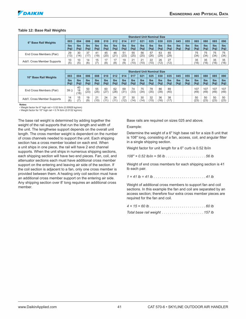
Table 12: Base Rail Weights
6" Base Rail Weights
Standard Unit Nominal Size
003 004 006 008 010 012 014 017 021 025 030 035 045 055 065 080 085 090
lbs (kg)
lbs (kg)
lbs (kg)
lbs (kg)
lbs (kg)
lbs (kg)
lbs (kg)
lbs (kg)
lbs (kg)
lbs (kg)
lbs (kg)
lbs (kg)
lbs (kg)
lbs (kg)
lbs (kg)
lbs (kg)
lbs (kg)
lbs (kg)
End Cross Members (Pair) 29 (13)
30 (14)
37 (17)
41 (19)
45 (20)
46 (21)
51 (23)
55 (25)
56 (25)
57 (26)
63 (29)
65 (29)
75 (34)
75 (34)
75 (34)
75 (34)
Add’l. Cross Member Supports 10 (5)
10 (5)
14 (6)
15 (7)
17 (8)
17 (8)
19 (9)
21 (10)
21 (10)
22 (10)
26 (12)
27 (12)
35 (16)
35 (16)
35 (16)
35 (16)
10" Base Rail Weights
Standard Unit Nominal Size
003 004 006 008 010 012 014 017 021 025 030 035 045 055 065 080 085 090
lbs (kg)
lbs (kg)
lbs (kg)
lbs (kg)
lbs (kg)
lbs (kg)
lbs (kg)
lbs (kg)
lbs (kg)
lbs (kg)
lbs (kg)
lbs (kg)
lbs (kg)
lbs (kg)
lbs (kg)
lbs (kg)
lbs (kg)
lbs (kg)
End Cross Members (Pair) 39 ()40 18
(18)50
(23)55
(25)60
(27)62
(28)69
(31)74
(33)75
(34)78
(35)86
(39)89
(40) 107 (49)
107 (49)
107 (49)
107 (49)
Add’l. Cross Member Supports 14 (6)
15 (7)
19 (9)
21 (10)
24 (11)
24 (11)
27 (12)
30 (14)
30 (14)
32 (15)
36 (16)
38 (17)
50 (23)
50 (23)
50 (23)
50 (23)
Notes: • Weight factor for 6" high rail = 0.52 lb/in (0.00929 kg/mm) • Weight factor for 10" high rail = 0.74 lb/in (0.0132 kg/mm)
The base rail weight is determined by adding together the weight of the rail supports that run the length and width of the unit. The lengthwise support depends on the overall unit length. The cross member weight is dependent on the number of cross channels needed to support the unit. Each shipping section has a cross member located on each end. When a unit ships in one piece, the rail will have 2 end channel supports. When the unit ships in numerous shipping sections, each shipping section will have two end pieces. Fan, coil, and attenuator sections each must have additional cross member support on the entering and leaving air side of the section. If the coil section is adjacent to a fan, only one cross member is provided between them. A heating only coil section must have an additional cross member support on the entering air side. Any shipping section over 8' long requires an additional cross member.
Base rails are required on sizes 025 and above.
Example:
Determine the weight of a 6" high base rail for a size 8 unit that is 108" long, consisting of a fan, access, coil, and angular ilter in a single shipping section.
Weight factor for unit length for a 6" curb is 0.52 lb/in
108" × 0.52 lb/in = 56 lb . . . . . . . . . . . . . . . . . . . . 56 lb
Weight of end cross members for each shipping section is 41 lb each pair.
1 × 41 lb = 41 lb . . . . . . . . . . . . . . . . . . . . . . . . . . 41 lb
Weight of additional cross members to support fan and coil sections. In this example the fan and coil are separated by an access section; therefore four extra cross member pieces are required for the fan and coil.
4 × 15 = 60 lb . . . . . . . . . . . . . . . . . . . . . . . . . . . . 60 lb
Total base rail weight . . . . . . . . . . . . . . . . . . . . . 157 lb
engineering and physiCal daTa
www.DaikinApplied.com 41 CAT 570-6 • SKYLINE OUTDOOR AIR HANDLER
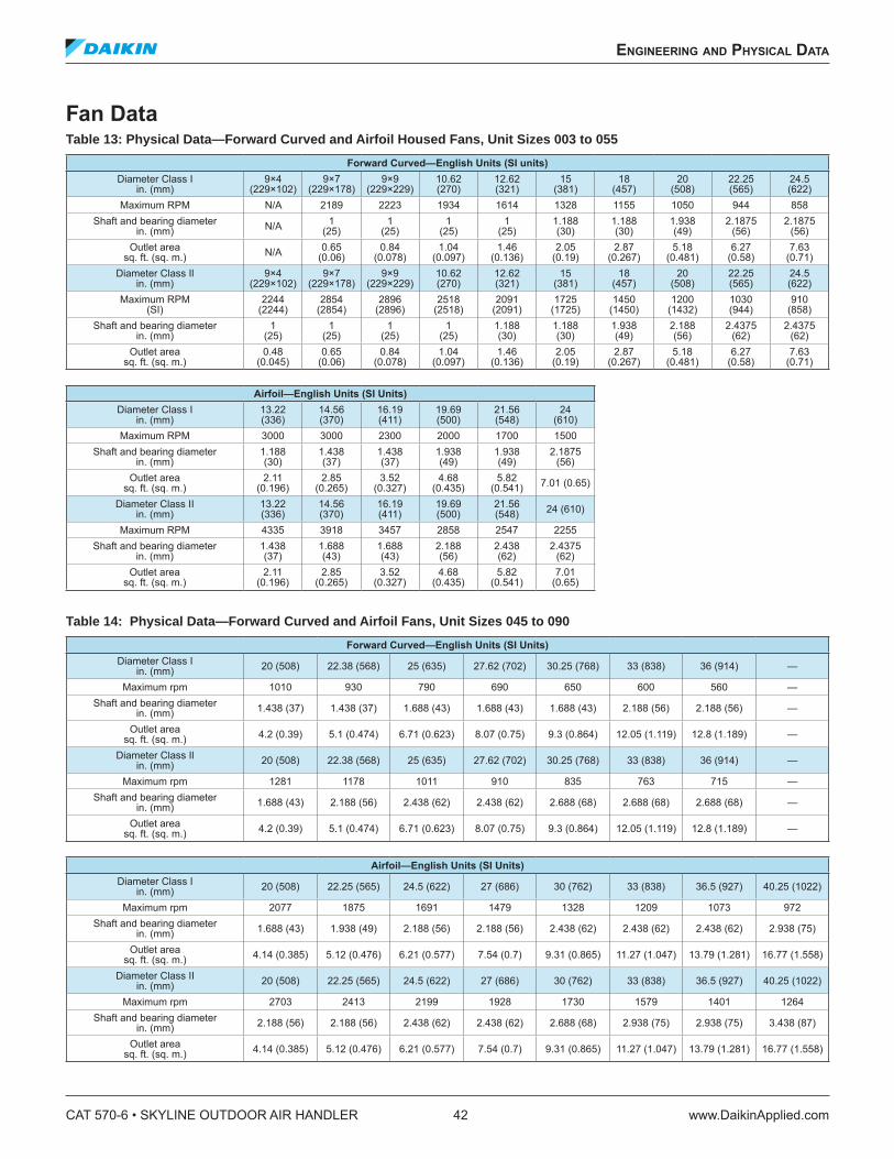
Fan Data Table 13: Physical Data—Forward Curved and Airfoil Housed Fans, Unit Sizes 003 to 055
Forward Curved—English Units (SI units)Diameter Class I
in. (mm)9×4
(229×102)9×7
(229×178)9×9
(229×229)10.62 (270)
12.62 (321)
15 (381)
18 (457)
20 (508)
22.25 (565)
24.5 (622)
Maximum RPM N/A 2189 2223 1934 1614 1328 1155 1050 944 858
Shaft and bearing diameter in. (mm) N/A 1
(25)1
(25)1
(25)1
(25)1.188 (30)
1.188 (30)
1.938 (49)
2.1875 (56)
2.1875 (56)
Outlet area sq. ft. (sq. m.) N/A 0.65
(0.06)0.84
(0.078) 1.04
(0.097)1.46
(0.136)2.05
(0.19)2.87
(0.267)5.18
(0.481)6.27
(0.58)7.63
(0.71)Diameter Class Il
in. (mm)9×4
(229×102)9×7
(229×178)9×9
(229×229)10.62 (270)
12.62 (321)
15 (381)
18 (457)
20 (508)
22.25 (565)
24.5 (622)
Maximum RPM (SI)
2244 (2244)
2854 (2854)
2896 (2896)
2518 (2518)
2091 (2091)
1725 (1725)
1450 (1450)
1200 (1432)
1030 (944)
910 (858)
Shaft and bearing diameter in. (mm)
1 (25)
1 (25)
1 (25)
1 (25)
1.188 (30)
1.188 (30)
1.938 (49)
2.188 (56)
2.4375 (62)
2.4375 (62)
Outlet area sq. ft. (sq. m.)
0.48 (0.045)
0.65 (0.06)
0.84 (0.078)
1.04 (0.097)
1.46 (0.136)
2.05 (0.19)
2.87 (0.267)
5.18 (0.481)
6.27 (0.58)
7.63 (0.71)
Airfoil—English Units (SI Units)Diameter Class I
in. (mm)13.22 (336)
14.56 (370)
16.19 (411)
19.69 (500)
21.56 (548)
24 (610)
Maximum RPM 3000 3000 2300 2000 1700 1500
Shaft and bearing diameter in. (mm)
1.188 (30)
1.438 (37)
1.438 (37)
1.938 (49)
1.938 (49)
2.1875 (56)
Outlet area sq. ft. (sq. m.)
2.11 (0.196)
2.85 (0.265)
3.52 (0.327)
4.68 (0.435)
5.82 (0.541) 7.01 (0.65)
Diameter Class II in. (mm)
13.22 (336)
14.56 (370)
16.19 (411)
19.69 (500)
21.56 (548) 24 (610)
Maximum RPM 4335 3918 3457 2858 2547 2255
Shaft and bearing diameter in. (mm)
1.438 (37)
1.688 (43)
1.688 (43)
2.188 (56)
2.438 (62)
2.4375 (62)
Outlet area sq. ft. (sq. m.)
2.11 (0.196)
2.85 (0.265)
3.52 (0.327)
4.68 (0.435)
5.82 (0.541)
7.01 (0.65)
Table 14: Physical Data—Forward Curved and Airfoil Fans, Unit Sizes 045 to 090
Forward Curved—English Units (SI Units)Diameter Class I
in. (mm) 20 (508) 22.38 (568) 25 (635) 27.62 (702) 30.25 (768) 33 (838) 36 (914) —
Maximum rpm 1010 930 790 690 650 600 560 —Shaft and bearing diameter
in. (mm) 1.438 (37) 1.438 (37) 1.688 (43) 1.688 (43) 1.688 (43) 2.188 (56) 2.188 (56) —
Outlet area sq. ft. (sq. m.) 4.2 (0.39) 5.1 (0.474) 6.71 (0.623) 8.07 (0.75) 9.3 (0.864) 12.05 (1.119) 12.8 (1.189) —
Diameter Class Il in. (mm) 20 (508) 22.38 (568) 25 (635) 27.62 (702) 30.25 (768) 33 (838) 36 (914) —
Maximum rpm 1281 1178 1011 910 835 763 715 —Shaft and bearing diameter
in. (mm) 1.688 (43) 2.188 (56) 2.438 (62) 2.438 (62) 2.688 (68) 2.688 (68) 2.688 (68) —
Outlet area sq. ft. (sq. m.) 4.2 (0.39) 5.1 (0.474) 6.71 (0.623) 8.07 (0.75) 9.3 (0.864) 12.05 (1.119) 12.8 (1.189) —
Airfoil—English Units (SI Units)Diameter Class I
in. (mm) 20 (508) 22.25 (565) 24.5 (622) 27 (686) 30 (762) 33 (838) 36.5 (927) 40.25 (1022)
Maximum rpm 2077 1875 1691 1479 1328 1209 1073 972
Shaft and bearing diameter in. (mm) 1.688 (43) 1.938 (49) 2.188 (56) 2.188 (56) 2.438 (62) 2.438 (62) 2.438 (62) 2.938 (75)
Outlet area sq. ft. (sq. m.) 4.14 (0.385) 5.12 (0.476) 6.21 (0.577) 7.54 (0.7) 9.31 (0.865) 11.27 (1.047) 13.79 (1.281) 16.77 (1.558)
Diameter Class II in. (mm) 20 (508) 22.25 (565) 24.5 (622) 27 (686) 30 (762) 33 (838) 36.5 (927) 40.25 (1022)
Maximum rpm 2703 2413 2199 1928 1730 1579 1401 1264
Shaft and bearing diameter in. (mm) 2.188 (56) 2.188 (56) 2.438 (62) 2.438 (62) 2.688 (68) 2.938 (75) 2.938 (75) 3.438 (87)
Outlet area sq. ft. (sq. m.) 4.14 (0.385) 5.12 (0.476) 6.21 (0.577) 7.54 (0.7) 9.31 (0.865) 11.27 (1.047) 13.79 (1.281) 16.77 (1.558)
CAT 570-6 • SKYLINE OUTDOOR AIR HANDLER 42 www.DaikinApplied.com
engineering and physiCal daTa
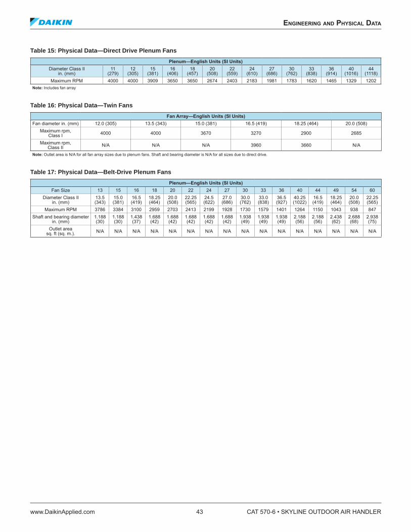
Table 15: Physical Data—Direct Drive Plenum Fans
Plenum—English Units (SI Units)Diameter Class Il
in. (mm)11
(279)12
(305)15
(381)16
(406)18
(457)20
(508)22
(559)24
(610)27
(686)30
(762)33
(838)36
(914)40
(1016)44
(1118)Maximum RPM 4000 4000 3909 3650 3650 2674 2403 2183 1981 1783 1620 1465 1329 1202
Note: Includes fan array
Table 16: Physical Data—Twin Fans
Fan Array—English Units (SI Units)Fan diameter in. (mm) 12.0 (305) 13.5 (343) 15.0 (381) 16.5 (419) 18.25 (464) 20.0 (508)
Maximum rpm, Class I 4000 4000 3670 3270 2900 2685
Maximum rpm, Class II N/A N/A N/A 3960 3660 N/A
Note: Outlet area is N/A for all fan array sizes due to plenum fans. Shaft and bearing diameter is N/A for all sizes due to direct drive.
Table 17: Physical Data—Belt-Drive Plenum Fans
Plenum—English Units (SI Units)Fan Size 13 15 16 18 20 22 24 27 30 33 36 40 44 49 54 60
Diameter Class Il in. (mm)
13.5 (343)
15.0 (381)
16.5 (419)
18.25 (464)
20.0 (508)
22.25 (565)
24.5 (622)
27.0 (686)
30.0 (762)
33.0 (838)
36.5 (927)
40.25 (1022)
16.5 (419)
18.25 (464)
20.0 (508)
22.25 (565)
Maximum RPM 3786 3384 3100 2959 2703 2413 2199 1928 1730 1579 1401 1264 1150 1043 938 847
Shaft and bearing diameter in. (mm)
1.188 (30)
1.188 (30)
1.438 (37)
1.688 (42)
1.688 (42)
1.688 (42)
1.688 (42)
1.688 (42)
1.938 (49)
1.938 (49)
1.938 (49)
2.188 (56)
2.188 (56)
2.438 (62)
2.688 (68)
2.938 (75)
Outlet area sq. ft (sq. m.). N/A N/A N/A N/A N/A N/A N/A N/A N/A N/A N/A N/A N/A N/A N/A N/A
engineering and physiCal daTa
www.DaikinApplied.com 43 CAT 570-6 • SKYLINE OUTDOOR AIR HANDLER
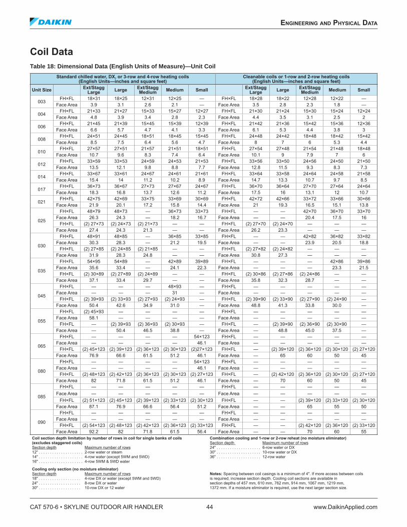
Coil Data
Table 18: Dimensional Data (English Units of Measure)—Unit Coil
Standard chilled water, DX, or 3-row and 4-row heating coils (English Units—inches and square feet)
Cleanable coils or 1-row and 2-row heating coils (English Units—inches and square feet)
Unit SizeExt/Stagg
LargeLarge
Ext/Stagg Medium
Medium SmallExt/Stagg
LargeLarge
Ext/Stagg Medium
Medium Small
003FH×FL 18×31 18×25 12×31 12×25 — FH×FL 18×28 18×22 12×28 12×22 —
Face Area 3.9 3.1 2.6 2.1 — Face Area 3.5 2.8 2.3 1.8 —
004FH×FL 21×33 21×27 15×33 15×27 12×27 FH×FL 21×30 21×24 15×30 15×24 12×24
Face Area 4.8 3.9 3.4 2.8 2.3 Face Area 4.4 3.5 3.1 2.5 2
006FH×FL 21×45 21×39 15×45 15×39 12×39 FH×FL 21×42 21×36 15×42 15×36 12×36
Face Area 6.6 5.7 4.7 4.1 3.3 Face Area 6.1 5.3 4.4 3.8 3
008FH×FL 24×51 24×45 18×51 18×45 15×45 FH×FL 24×48 24×42 18×48 18×42 15×42
Face Area 8.5 7.5 6.4 5.6 4.7 Face Area 8 7 6 5.3 4.4
010FH×FL 27×57 27×51 21×57 21×51 18×51 FH×FL 27×54 27×48 21×54 21×48 18×48
Face Area 10.7 9.6 8.3 7.4 6.4 Face Area 10.1 9 7.9 7 6
012FH×FL 33×59 33×53 24×59 24×53 21×53 FH×FL 33×56 33×50 24×56 24×50 21×50
Face Area 13.5 12.1 9.8 8.8 7.7 Face Area 12.8 11.5 9.3 8.3 7.3
014FH×FL 33×67 33×61 24×67 24×61 21×61 FH×FL 33×64 33×58 24×64 24×58 21×58
Face Area 15.4 14 11.2 10.2 8.9 Face Area 14.7 13.3 10.7 9.7 8.5
017FH×FL 36×73 36×67 27×73 27×67 24×67 FH×FL 36×70 36×64 27×70 27×64 24×64
Face Area 18.3 16.8 13.7 12.6 11.2 Face Area 17.5 16 13.1 12 10.7
021FH×FL 42×75 42×69 33×75 33×69 30×69 FH×FL 42×72 42×66 33×72 33×66 30×66
Face Area 21.9 20.1 17.2 15.8 14.4 Face Area 21 19.3 16.5 15.1 13.8
025
FH×FL 48×79 48×73 — 36×73 33×73 FH×FL — — 42×70 36×70 33×70Face Area 26.3 24.3 — 18.2 16.7 Face Area — — 20.4 17.5 16
FH×FL (2) 27×73 (2) 24×73 (2) 21×73 — — FH×FL (2) 27×70 (2) 24×70 — — —Face Area 27.4 24.3 21.3 — — Face Area 26.2 23.3 — — —
030
FH×FL 48×91 48×85 — 36×85 33×85 FH×FL — — 42×82 36×82 33×82Face Area 30.3 28.3 — 21.2 19.5 Face Area — — 23.9 20.5 18.8
FH×FL (2) 27×85 (2) 24×85 (2) 21×85 — — FH×FL (2) 27×82 (2) 24×82 — — —Face Area 31.9 28.3 24.8 — — Face Area 30.8 27.3 — — —
035
FH×FL 54×95 54×89 — 42×89 39×89 FH×FL — — — 42×86 39×86Face Area 35.6 33.4 — 24.1 22.3 Face Area — — — 23.3 21.5
FH×FL (2) 30×89 (2) 27×89 (2) 24×89 — — FH×FL (2) 30×86 (2) 27×86 (2) 24×86 — —Face Area 37.1 33.4 29.7 — — Face Area 35.8 32.3 28.7 — —
045
FH×FL — — — 48×93 — FH×FL — — — — —Face Area — — — 31 — Face Area — — — — —
FH×FL (2) 39×93 (2) 33×93 (2) 27×93 (2) 24×93 — FH×FL (2) 39×90 (2) 33×90 (2) 27×90 (2) 24×90 —Face Area 50.4 42.6 34.9 31.0 — Face Area 48.8 41.3 33.8 30.0 —
055
FH×FL (2) 45×93 — — — — FH×FL — — — — —Face Area 58.1 — — — — Face Area — — — — —
FH×FL — (2) 39×93 (2) 36×93 (2) 30×93 — FH×FL — (2) 39×90 (2) 36×90 (2) 30×90 —Face Area — 50.4 46.5 38.8 — Face Area — 48.8 45.0 37.5 —
065
FH×FL — — — — 54×123 FH×FL — — — — —Face Area — — — — 46.1 Face Area — — — — —
FH×FL (2) 45×123 (2) 39×123 (2) 36×123 (2) 30×123 (2)27×123 FH×FL — (2) 39×120 (2) 36×120 (2) 30×120 (2) 27×120Face Area 76.9 66.6 61.5 51.2 46.1 Face Area — 65 60 50 45
080
FH×FL — — — — 54×123 FH×FL — — — — —Face Area — — — — 46.1 Face Area — — — — —
FH×FL (2) 48×123 (2) 42×123 (2) 36×123 (2) 30×123 (2) 27×123 FH×FL — (2) 42×120 (2) 36×120 (2) 30×120 (2) 27×120Face Area 82 71.8 61.5 51.2 46.1 Face Area — 70 60 50 45
085
FH×FL — — — — — FH×FL — — — — —Face Area — — — — — Face Area — — — — —
FH×FL (2) 51×123 (2) 45×123 (2) 39×123 (2) 33×123 (2) 30×123 FH×FL — — (2) 39×120 (2) 33×120 (2) 30×120Face Area 87.1 76.9 66.6 56.4 51.2 Face Area — — 65 55 50
090
FH×FL — — — — — FH×FL — — — — —Face Area — — — — — Face Area — — — — —
FH×FL (2) 54×123 (2) 48×123 (2) 42×123 (2) 36×123 (2) 33×123 FH×FL — — (2) 42×120 (2) 36×120 (2) 33×120Face Area 92.2 82 71.8 61.5 56.4 Face Area — — 70 60 55
Coil section depth limitation by number of rows in coil for single banks of coils Combination cooling and 1-row or 2-row reheat (no moisture eliminator) (excludes staggered coils) Section depth Maximum number of rows Section depth Maximum number of rows 24" . . . . . . . . . . . . . . . . . . . . 6-row water or DX 12" . . . . . . . . . . . . . . . . . . . . 2-row water or steam 30" . . . . . . . . . . . . . . . . . . . . 10-row water or DX 14" . . . . . . . . . . . . . . . . . . . . 4-row water (except 5WM and 5WD) 36" . . . . . . . . . . . . . . . . . . . . 12-row water 16" . . . . . . . . . . . . . . . . . . . . 4-row 5WM & 5WD water
Cooling only section (no moisture eliminator) Section depth Maximum number of rows Notes: Spacing between coil casings is a minimum of 4". If more access between coils 18" . . . . . . . . . . . . . . . . . . . 4-row DX or water (except 5WM and 5WD) is required, increase section depth. Cooling coil sections are available in 24" . . . . . . . . . . . . . . . . . . . 8-row DX or water section depths of 457 mm, 610 mm, 762 mm, 914 mm, 1067 mm, 1219 mm, 30" . . . . . . . . . . . . . . . . . . . 10-row DX or 12 water 1372 mm. If a moisture eliminator is required, use the next larger section size.
CAT 570-6 • SKYLINE OUTDOOR AIR HANDLER 44 www.DaikinApplied.com
engineering and physiCal daTa
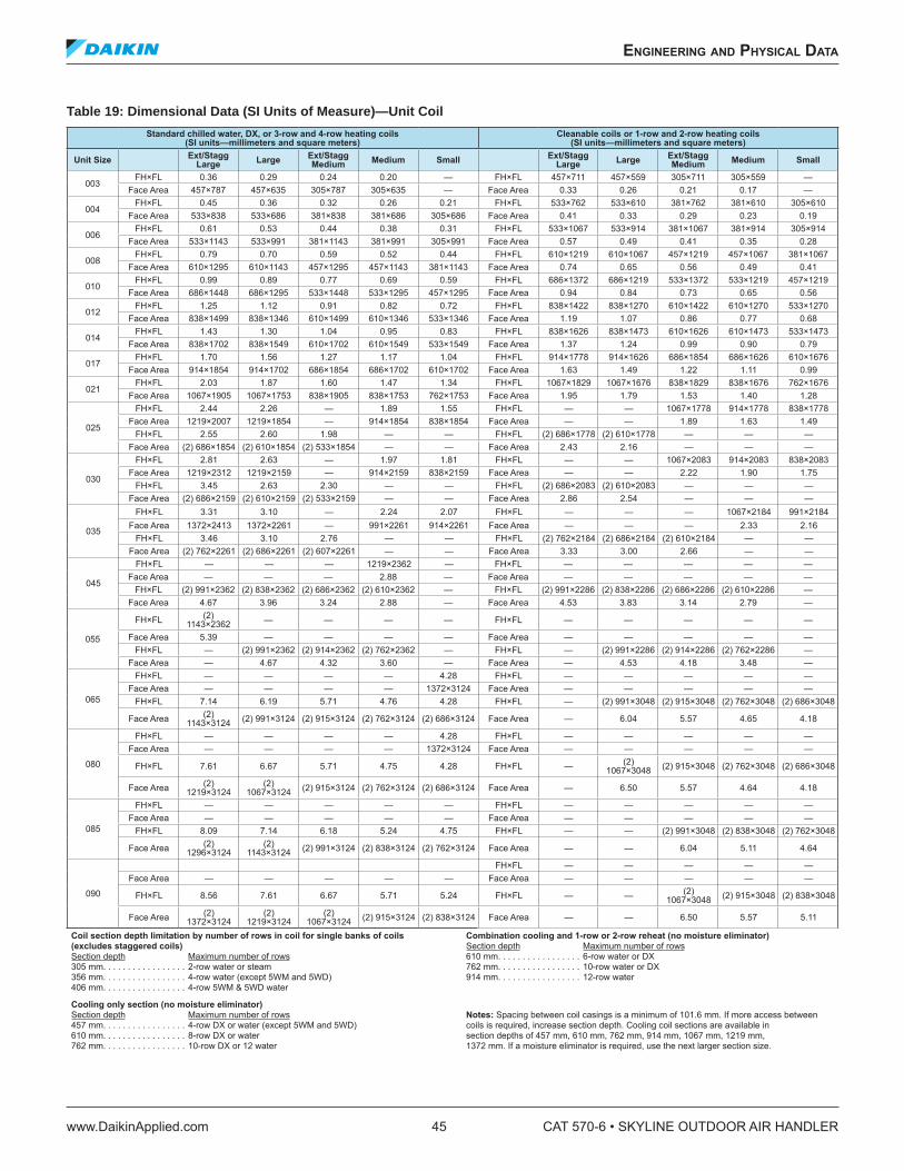
Table 19: Dimensional Data (SI Units of Measure)—Unit Coil
Standard chilled water, DX, or 3-row and 4-row heating coils (SI units—millimeters and square meters)
Cleanable coils or 1-row and 2-row heating coils (SI units—millimeters and square meters)
Unit SizeExt/Stagg
LargeLarge
Ext/Stagg Medium
Medium SmallExt/Stagg
LargeLarge
Ext/Stagg Medium
Medium Small
003FH×FL 0.36 0.29 0.24 0.20 — FH×FL 457×711 457×559 305×711 305×559 —
Face Area 457×787 457×635 305×787 305×635 — Face Area 0.33 0.26 0.21 0.17 —
004FH×FL 0.45 0.36 0.32 0.26 0.21 FH×FL 533×762 533×610 381×762 381×610 305×610
Face Area 533×838 533×686 381×838 381×686 305×686 Face Area 0.41 0.33 0.29 0.23 0.19
006FH×FL 0.61 0.53 0.44 0.38 0.31 FH×FL 533×1067 533×914 381×1067 381×914 305×914
Face Area 533×1143 533×991 381×1143 381×991 305×991 Face Area 0.57 0.49 0.41 0.35 0.28
008FH×FL 0.79 0.70 0.59 0.52 0.44 FH×FL 610×1219 610×1067 457×1219 457×1067 381×1067
Face Area 610×1295 610×1143 457×1295 457×1143 381×1143 Face Area 0.74 0.65 0.56 0.49 0.41
010FH×FL 0.99 0.89 0.77 0.69 0.59 FH×FL 686×1372 686×1219 533×1372 533×1219 457×1219
Face Area 686×1448 686×1295 533×1448 533×1295 457×1295 Face Area 0.94 0.84 0.73 0.65 0.56
012FH×FL 1.25 1.12 0.91 0.82 0.72 FH×FL 838×1422 838×1270 610×1422 610×1270 533×1270
Face Area 838×1499 838×1346 610×1499 610×1346 533×1346 Face Area 1.19 1.07 0.86 0.77 0.68
014FH×FL 1.43 1.30 1.04 0.95 0.83 FH×FL 838×1626 838×1473 610×1626 610×1473 533×1473
Face Area 838×1702 838×1549 610×1702 610×1549 533×1549 Face Area 1.37 1.24 0.99 0.90 0.79
017FH×FL 1.70 1.56 1.27 1.17 1.04 FH×FL 914×1778 914×1626 686×1854 686×1626 610×1676
Face Area 914×1854 914×1702 686×1854 686×1702 610×1702 Face Area 1.63 1.49 1.22 1.11 0.99
021FH×FL 2.03 1.87 1.60 1.47 1.34 FH×FL 1067×1829 1067×1676 838×1829 838×1676 762×1676
Face Area 1067×1905 1067×1753 838×1905 838×1753 762×1753 Face Area 1.95 1.79 1.53 1.40 1.28
025
FH×FL 2.44 2.26 — 1.89 1.55 FH×FL — — 1067×1778 914×1778 838×1778Face Area 1219×2007 1219×1854 — 914×1854 838×1854 Face Area — — 1.89 1.63 1.49
FH×FL 2.55 2.60 1.98 — — FH×FL (2) 686×1778 (2) 610×1778 — — —Face Area (2) 686×1854 (2) 610×1854 (2) 533×1854 — — Face Area 2.43 2.16 — — —
030
FH×FL 2.81 2.63 — 1.97 1.81 FH×FL — — 1067×2083 914×2083 838×2083Face Area 1219×2312 1219×2159 — 914×2159 838×2159 Face Area — — 2.22 1.90 1.75
FH×FL 3.45 2.63 2.30 — — FH×FL (2) 686×2083 (2) 610×2083 — — —Face Area (2) 686×2159 (2) 610×2159 (2) 533×2159 — — Face Area 2.86 2.54 — — —
035
FH×FL 3.31 3.10 — 2.24 2.07 FH×FL — — — 1067×2184 991×2184Face Area 1372×2413 1372×2261 — 991×2261 914×2261 Face Area — — — 2.33 2.16
FH×FL 3.46 3.10 2.76 — — FH×FL (2) 762×2184 (2) 686×2184 (2) 610×2184 — —Face Area (2) 762×2261 (2) 686×2261 (2) 607×2261 — — Face Area 3.33 3.00 2.66 — —
045
FH×FL — — — 1219×2362 — FH×FL — — — — —Face Area — — — 2.88 — Face Area — — — — —
FH×FL (2) 991×2362 (2) 838×2362 (2) 686×2362 (2) 610×2362 — FH×FL (2) 991×2286 (2) 838×2286 (2) 686×2286 (2) 610×2286 —Face Area 4.67 3.96 3.24 2.88 — Face Area 4.53 3.83 3.14 2.79 —
055
FH×FL (2) 1143×2362 — — — — FH×FL — — — — —
Face Area 5.39 — — — — Face Area — — — — —FH×FL — (2) 991×2362 (2) 914×2362 (2) 762×2362 — FH×FL — (2) 991×2286 (2) 914×2286 (2) 762×2286 —
Face Area — 4.67 4.32 3.60 — Face Area — 4.53 4.18 3.48 —
065
FH×FL — — — — 4.28 FH×FL — — — — —Face Area — — — — 1372×3124 Face Area — — — — —
FH×FL 7.14 6.19 5.71 4.76 4.28 FH×FL — (2) 991×3048 (2) 915×3048 (2) 762×3048 (2) 686×3048
Face Area (2) 1143×3124 (2) 991×3124 (2) 915×3124 (2) 762×3124 (2) 686×3124 Face Area — 6.04 5.57 4.65 4.18
080
FH×FL — — — — 4.28 FH×FL — — — — —Face Area — — — — 1372×3124 Face Area — — — — —
FH×FL 7.61 6.67 5.71 4.75 4.28 FH×FL — (2) 1067×3048 (2) 915×3048 (2) 762×3048 (2) 686×3048
Face Area (2) 1219×3124
(2) 1067×3124 (2) 915×3124 (2) 762×3124 (2) 686×3124 Face Area — 6.50 5.57 4.64 4.18
085
FH×FL — — — — — FH×FL — — — — —Face Area — — — — — Face Area — — — — —
FH×FL 8.09 7.14 6.18 5.24 4.75 FH×FL — — (2) 991×3048 (2) 838×3048 (2) 762×3048
Face Area (2) 1296×3124
(2) 1143×3124 (2) 991×3124 (2) 838×3124 (2) 762×3124 Face Area — — 6.04 5.11 4.64
090
FH×FL — — — — —Face Area — — — — — Face Area — — — — —
FH×FL 8.56 7.61 6.67 5.71 5.24 FH×FL — — (2) 1067×3048 (2) 915×3048 (2) 838×3048
Face Area (2) 1372×3124
(2) 1219×3124
(2) 1067×3124 (2) 915×3124 (2) 838×3124 Face Area — — 6.50 5.57 5.11
Coil section depth limitation by number of rows in coil for single banks of coils Combination cooling and 1-row or 2-row reheat (no moisture eliminator) (excludes staggered coils) Section depth Maximum number of rows Section depth Maximum number of rows 610 mm. . . . . . . . . . . . . . . . . 6-row water or DX 305 mm. . . . . . . . . . . . . . . . . 2-row water or steam 762 mm. . . . . . . . . . . . . . . . . 10-row water or DX 356 mm. . . . . . . . . . . . . . . . . 4-row water (except 5WM and 5WD) 914 mm. . . . . . . . . . . . . . . . . 12-row water 406 mm. . . . . . . . . . . . . . . . . 4-row 5WM & 5WD water
Cooling only section (no moisture eliminator) Section depth Maximum number of rows Notes: Spacing between coil casings is a minimum of 101.6 mm. If more access between 457 mm. . . . . . . . . . . . . . . . . 4-row DX or water (except 5WM and 5WD) coils is required, increase section depth. Cooling coil sections are available in 610 mm. . . . . . . . . . . . . . . . . 8-row DX or water section depths of 457 mm, 610 mm, 762 mm, 914 mm, 1067 mm, 1219 mm, 762 mm. . . . . . . . . . . . . . . . . 10-row DX or 12 water 1372 mm. If a moisture eliminator is required, use the next larger section size.
engineering and physiCal daTa
www.DaikinApplied.com 45 CAT 570-6 • SKYLINE OUTDOOR AIR HANDLER
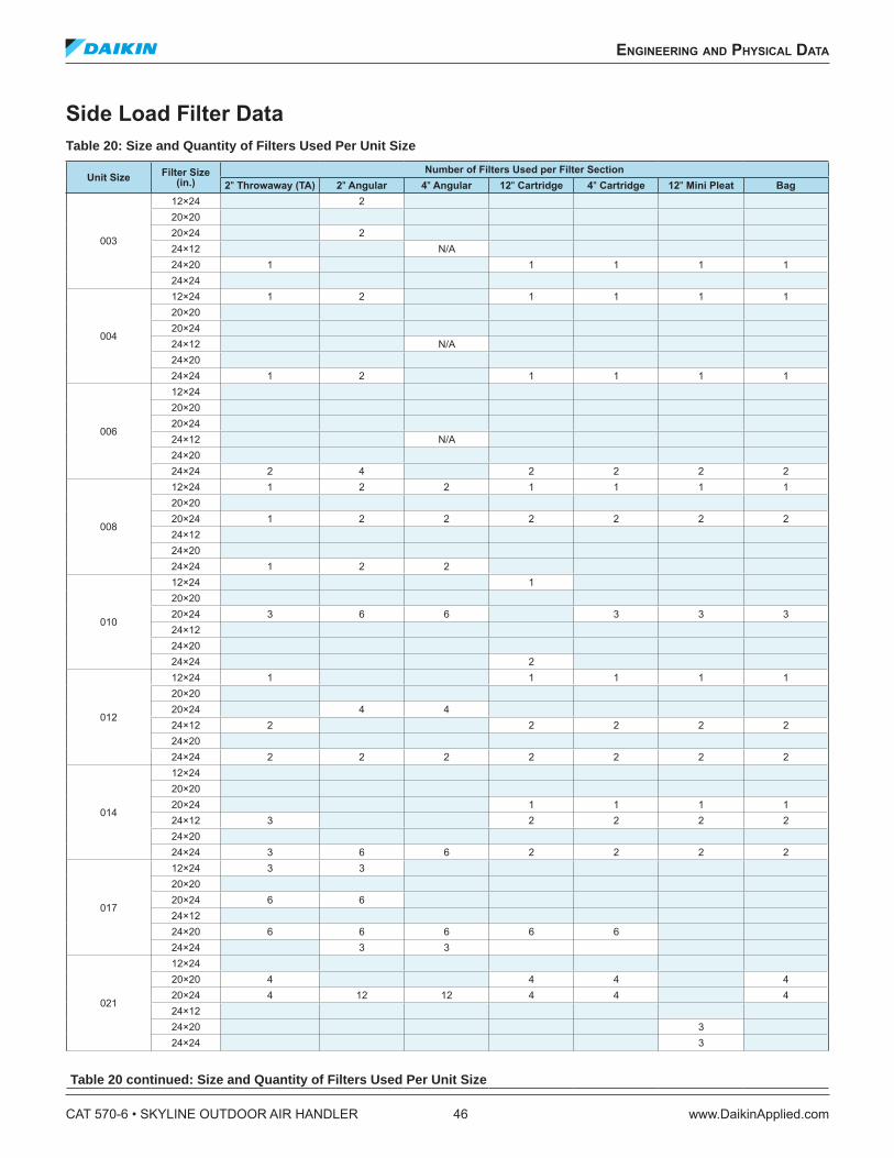
Side Load Filter Data
Table 20: Size and Quantity of Filters Used Per Unit Size
Unit Size Filter Size
(in.) Number of Filters Used per Filter Section
2" Throwaway (TA) 2" Angular 4" Angular 12" Cartridge 4" Cartridge 12" Mini Pleat Bag
003
12×24 2
20×2020×24 2
24×12 N/A24×20 1 1 1 1 1
24×24
004
12×24 1 2 1 1 1 1
20×2020×2424×12 N/A24×2024×24 1 2 1 1 1 1
006
12×2420×2020×2424×12 N/A24×2024×24 2 4 2 2 2 2
008
12×24 1 2 2 1 1 1 1
20×2020×24 1 2 2 2 2 2 2
24×1224×2024×24 1 2 2
010
12×24 1
20×2020×24 3 6 6 3 3 3
24×1224×2024×24 2
012
12×24 1 1 1 1 1
20×2020×24 4 4
24×12 2 2 2 2 2
24×2024×24 2 2 2 2 2 2 2
014
12×2420×2020×24 1 1 1 1
24×12 3 2 2 2 2
24×2024×24 3 6 6 2 2 2 2
017
12×24 3 3
20×2020×24 6 6
24×1224×20 6 6 6 6 6
24×24 3 3
021
12×2420×20 4 4 4 4
20×24 4 12 12 4 4 4
24×1224×20 3
24×24 3
Table 20 continued: Size and Quantity of Filters Used Per Unit Size
CAT 570-6 • SKYLINE OUTDOOR AIR HANDLER 46 www.DaikinApplied.com
engineering and physiCal daTa
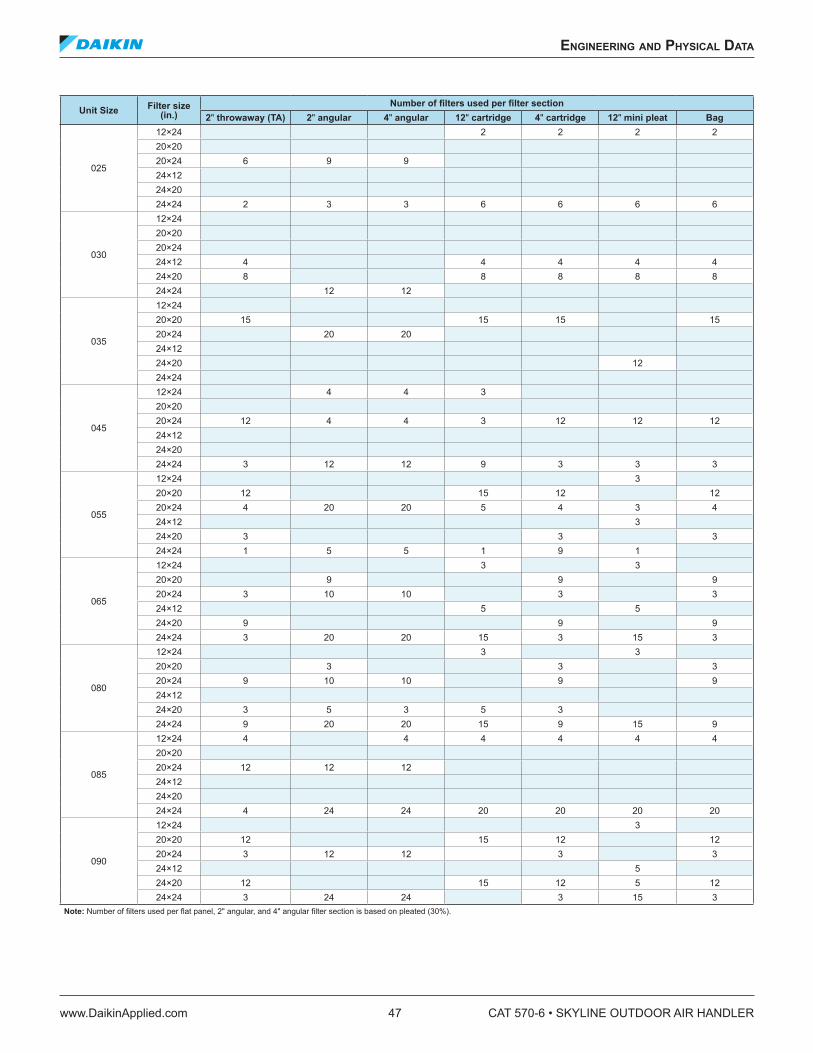
Unit Size Filter size
(in.) Number of ilters used per ilter section
2" throwaway (TA) 2" angular 4" angular 12" cartridge 4" cartridge 12" mini pleat Bag
025
12×24 2 2 2 2
20×2020×24 6 9 9
24×1224×2024×24 2 3 3 6 6 6 6
030
12×2420×2020×2424×12 4 4 4 4 4
24×20 8 8 8 8 8
24×24 12 12
035
12×2420×20 15 15 15 15
20×24 20 20
24×1224×20 12
24×24
045
12×24 4 4 3
20×2020×24 12 4 4 3 12 12 12
24×1224×2024×24 3 12 12 9 3 3 3
055
12×24 3
20×20 12 15 12 12
20×24 4 20 20 5 4 3 4
24×12 3
24×20 3 3 3
24×24 1 5 5 1 9 1
065
12×24 3 3
20×20 9 9 9
20×24 3 10 10 3 3
24×12 5 5
24×20 9 9 9
24×24 3 20 20 15 3 15 3
080
12×24 3 3
20×20 3 3 3
20×24 9 10 10 9 9
24×1224×20 3 5 3 5 3
24×24 9 20 20 15 9 15 9
085
12×24 4 4 4 4 4 4
20×2020×24 12 12 12
24×1224×2024×24 4 24 24 20 20 20 20
090
12×24 3
20×20 12 15 12 12
20×24 3 12 12 3 3
24×12 5
24×20 12 15 12 5 12
24×24 3 24 24 3 15 3
Note: Number of ilters used per lat panel, 2" angular, and 4" angular ilter section is based on pleated (30%).
engineering and physiCal daTa
www.DaikinApplied.com 47 CAT 570-6 • SKYLINE OUTDOOR AIR HANDLER
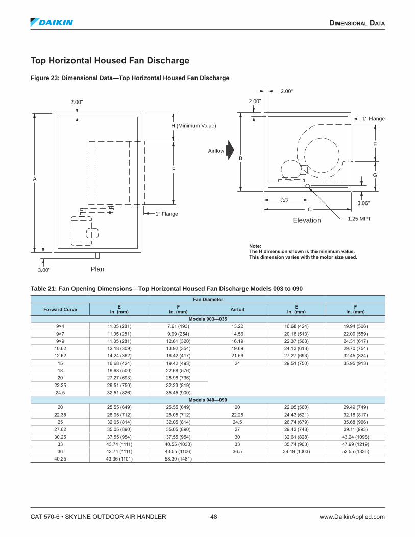
dimensional daTa
Top Horizontal Housed Fan Discharge
Figure 23: Dimensional Data—Top Horizontal Housed Fan Discharge
Table 21: Fan Opening Dimensions—Top Horizontal Housed Fan Discharge Models 003 to 090
Fan Diameter
Forward CurveE
in. (mm)F
in. (mm) AirfoilE
in. (mm)F
in. (mm)Models 003—035
9×4 11.05 (281) 7.61 (193) 13.22 16.68 (424) 19.94 (506)9×7 11.05 (281) 9.99 (254) 14.56 20.18 (513) 22.00 (559)9×9 11.05 (281) 12.61 (320) 16.19 22.37 (568) 24.31 (617)
10.62 12.18 (309) 13.92 (354) 19.69 24.13 (613) 29.70 (754)12.62 14.24 (362) 16.42 (417) 21.56 27.27 (693) 32.45 (824)
15 16.68 (424) 19.42 (493) 24 29.51 (750) 35.95 (913)18 19.68 (500) 22.68 (576)20 27.27 (693) 28.98 (736)
22.25 29.51 (750) 32.23 (819)24.5 32.51 (826) 35.45 (900)
Models 040—090
20 25.55 (649) 25.55 (649) 20 22.05 (560) 29.49 (749)22.38 28.05 (712) 28.05 (712) 22.25 24.43 (621) 32.18 (817)
25 32.05 (814) 32.05 (814) 24.5 26.74 (679) 35.68 (906)27.62 35.05 (890) 35.05 (890) 27 29.43 (748) 39.11 (993)30.25 37.55 (954) 37.55 (954) 30 32.61 (828) 43.24 (1098)
33 43.74 (1111) 40.55 (1030) 33 35.74 (908) 47.99 (1219)36 43.74 (1111) 43.55 (1106) 36.5 39.49 (1003) 52.55 (1335)
40.25 43.36 (1101) 58.30 (1481)
2.00"
3.00"
1" Flange
Airflow
2.00"
2.00"
1" Flange
Plan
Elevation 1.25 MPT
3.06"
A
H (Minimum Value)
F
C/2
C
G
E
B
Note: The H dimension shown is the minimum value. This dimension varies with the motor size used.
CAT 570-6 • SKYLINE OUTDOOR AIR HANDLER 48 www.DaikinApplied.com
dimensional daTa
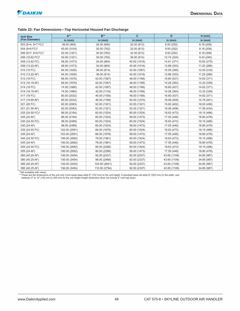
Table 22: Fan Dimensions—Top Horizontal Housed Fan Discharge
Unit Size (Fan Diameter)
A** B** C G H (min)in (mm) in (mm) in (mm) in (mm) in (mm)
003 (9×4, 9×7 FC)* 38.00 (965) 26.00 (660) 32.00 (813) 9.93 (252) 8.18 (208)004 (9×9 FC)* 40.00 (1016) 30.00 (762) 32.00 (813) 9.93 (252) 8.18 (208)006 (9×7, 9×9 FC)* 52.00 (1321) 30.00 (762) 32.00 (813) 9.93 (252) 8.18 (208)006 (10.62 FC)* 52.00 (1321) 30.00 (762) 36.00 (914) 12.74 (324) 9.43 (240)008 (12.62 FC) 58.00 (1473) 34.00 (864) 40.00 (1016) 14.61 (371) 10.83 (275)008 (13.22 AF) 58.00 (1473) 34.00 (864) 40.00 (1016) 13.88 (353) 11.25 (286)010 (15 FC) 64.00 (1626) 36.00 (914) 42.00 (1067) 15.55 (395) 12.50 (318)010 (13.22 AF) 64.00 (1626) 36.00 (914) 40.00 (1016) 13.88 (353) 11.25 (286)012 (18 FC) 66.00 (1676) 42.00 (1067) 46.00 (1168) 16.80 (427) 14.62 (371)012 (16.19 AF) 66.00 (1676) 42.00 (1067) 46.00 (1168) 14.28 (363) 13.33 (339)014 (18 FC) 74.00 (1880) 42.00 (1067) 46.00 (1168) 16.80 (427) 14.62 (371)014 (16.19 AF) 74.00 (1880) 42.00 (1118) 46.00 (1168) 14.28 (363) 13.33 (339)017 (18 FC) 80.00 (2032) 46.00 (1168) 46.00 (1168) 16.80 (427) 14.62 (371)017 (19.69 AF) 80.00 (2032) 46.00 (1168) 50.00 (1270) 16.09 (409) 15.78 (401)021 (20 FC) 82.00 (2083) 52.00 (1321) 52.00 (1321) 15.82 (402) 16.00 (406)021 (21.56 AF) 82.00 (2083) 52.00 (1321) 52.00 (1321) 16.06 (408) 17.09 (434)025 (24.50 FC)* 86.00 (2184) 60.00 (1524) 60.00 (1524) 18.63 (473) 19.15 (486)025 (24 AF) 86.00 (2184) 60.00 (1524) 58.00 (1473) 17.55 (446) 18.80 (478)030 (24.50 FC) 98.00 (2489) 60.00 (1524) 60.00 (1524) 18.63 (473) 19.15 (486)030 (24 AF) 98.00 (2489) 60.00 (1524) 58.00 (1473) 17.55 (446) 18.80 (478)035 (24.50 FC) 102.00 (2591) 66.00 (1676) 60.00 (1524) 18.63 (473) 19.15 (486)035 (24 AF) 102.00 (2591) 66.00 (1676) 58.00 (1473) 17.55 (446) 18.80 (478)045 (24.50 FC) 106.00 (2692) 78.00 (1981) 60.00 (1524) 18.63 (473) 19.15 (486)045 (24 AF) 106.00 (2692) 78.00 (1981) 58.00 (1473) 17.55 (446) 18.80 (478)055 (24.50 FC) 106.00 (2692) 90.00 (2286) 60.00 (1524) 18.63 (473) 19.15 (486)055 (24 AF) 106.00 (2692) 90.00 (2286) 58.00 (1473) 17.55 (446) 18.80 (478)065 (40.25 AF) 136.00 (3454) 92.00 (2337) 92.00 (2337) 43.65 (1109) 34.85 (987)080 (40.25 AF) 136.00 (3454) 98.00 (2489) 92.00 (2337) 43.65 (1109) 34.85 (987)085 (40.25 AF) 136.00 (3454) 104.00 (2641) 92.00 (2337) 43.65 (1109) 34.85 (987)090 (40.25 AF) 136.00 (3454) 110.00 (2794) 92.00 (2337) 43.65 (1109) 34.85 (987)
* Not available with vanes. ** These are the dimensions of the unit only Curb-ready base adds 6" (152 mm) to the unit height. A standard base rail adds 8" (203 mm) to the width, and between 4" to 12" (102 mm to 305 mm) to the unit height.Height dimension does not include 2" roof cap seam.
dimensional daTa
www.DaikinApplied.com 49 CAT 570-6 • SKYLINE OUTDOOR AIR HANDLER

Bottom Horizontal Housed Fan Discharge
Figure 24: Dimensional Data—Bottom Horizontal Housed Fan Discharge
Table 23: Fan Opening Dimensions— Bottom Horizontal Housed Fan Discharge Models 003 to 090
Fan Diameter
Forward CurveE
in. (mm)F
in. (mm) AirfoilE
in. (mm)F
in. (mm)Models 003—035
9×4 11.05 (281) 7.61 (193) 13.22 16.68 (424) 19.94 (506)9×7 11.05 (281) 9.99 (254) 14.56 20.18 (513) 22.00 (559)9×9 11.05 (281) 12.61 (320) 16.19 22.37 (568) 24.31 (617)
10.62 12.18 (309) 13.92 (354) 19.69 24.13 (613) 29.70 (754)12.62 14.24 (362) 16.42 (417) 21.56 27.27 (693) 32.45 (824)
15 16.68 (424) 19.42 (493) 24 29.51 (750) 35.95 (913)18 19.68 (500) 22.68 (576)20 27.27 (693) 28.98 (736)
22.25 29.51 (750) 32.23 (819)24.5 32.51 (826) 35.45 (900)
Models 040—090
20 25.55 (649) 25.55 (649) 20 22.05 (560) 29.49 (749)22.38 28.05 (712) 28.05 (712) 22.25 24.43 (621) 32.18 (817)
25 32.05 (814) 32.05 (814) 24.5 26.74 (679) 35.68 (906)27.62 35.05 (890) 35.05 (890) 27 29.43 (748) 39.11 (993)30.25 37.55 (954) 37.55 (954) 30 32.61 (828) 43.24 (1098)
33 43.74 (1111) 40.55 (1030) 33 35.74 (908) 47.99 (1219)36 43.74 (1111) 43.55 (1106) 36.5 39.49 (1003) 52.55 (1335)
40.25 43.36 (1101) 58.30 (1481)
2.00"
3.00"
1" Flange
Plan
A
H (Minimum Value)
F
Airflow
2.00"
2.00"
1" Flange
Elevation 1.25 MPT
3.06"C/2
C
G
EB
2.00"
Note: The H dimension shown is the minimum value. This dimension varies with the motor size used.
CAT 570-6 • SKYLINE OUTDOOR AIR HANDLER 50 www.DaikinApplied.com
dimensional daTa
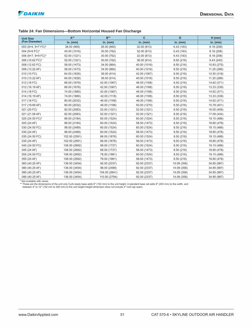
Table 24: Fan Dimensions—Bottom Horizontal Housed Fan Discharge
Unit Size (Fan Diameter)
A** B** C G H (min)in. (mm) in. (mm) in. (mm) in. (mm) in. (mm)
003 (9×4, 9×7 FC)* 38.00 (965) 26.00 (660) 32.00 (813) 6.43 (163) 8.18 (208)004 (9×9 FC)* 40.00 (1016) 30.00 (762) 32.00 (813) 6.43 (163) 8.18 (208)006 (9×7, 9×9 FC)* 52.00 (1321) 30.00 (762) 32.00 (813) 6.43 (163) 8.18 (208)006 (10.62 FC)* 52.00 (1321) 30.00 (762) 36.00 (914) 8.50 (216) 9.43 (240)008 (12.62 FC) 58.00 (1473) 34.00 (864) 40.00 (1016) 8.50 (216) 10.83 (275)008 (13.22 AF) 58.00 (1473) 34.00 (864) 40.00 (1016) 8.50 (216) 11.25 (286)010 (15 FC) 64.00 (1626) 36.00 (914) 42.00 (1067) 8.50 (216) 12.50 (318)010 (13.22 AF) 64.00 (1626) 36.00 (914) 40.00 (1016) 8.50 (216) 11.25 (286)012 (18 FC) 66.00 (1676) 42.00 (1067) 46.00 (1168) 8.50 (216) 14.62 (371)012 (16.19 AF) 66.00 (1676) 42.00 (1067) 46.00 (1168) 8.50 (216) 13.33 (339)014 (18 FC) 74.00 (1880) 42.00 (1067) 46.00 (1168) 8.50 (216) 14.62 (371)014 (16.19 AF) 74.00 (1880) 42.00 (1118) 46.00 (1168) 8.50 (216) 13.33 (339)017 (18 FC) 80.00 (2032) 46.00 (1168) 46.00 (1168) 8.50 (216) 14.62 (371)017 (19.69 AF) 80.00 (2032) 46.00 (1168) 50.00 (1270) 8.50 (216) 15.78 (401)021 (20 FC) 82.00 (2083) 52.00 (1321) 52.00 (1321) 8.50 (216) 16.00 (406)021 (21.56 AF) 82.00 (2083) 52.00 (1321) 52.00 (1321) 8.50 (216) 17.09 (434)025 (24.50 FC)* 86.00 (2184) 60.00 (1524) 60.00 (1524) 8.50 (216) 19.15 (486)025 (24 AF) 86.00 (2184) 60.00 (1524) 58.00 (1473) 8.50 (216) 18.80 (478)030 (24.50 FC) 98.00 (2489) 60.00 (1524) 60.00 (1524) 8.50 (216) 19.15 (486)030 (24 AF) 98.00 (2489) 60.00 (1524) 58.00 (1473) 8.50 (216) 18.80 (478)035 (24.50 FC) 102.00 (2591) 66.00 (1676) 60.00 (1524) 8.50 (216) 19.15 (486)035 (24 AF) 102.00 (2591) 66.00 (1676) 58.00 (1473) 8.50 (216) 18.80 (478)045 (24.50 FC) 106.00 (2692) 68.00 (1727) 60.00 (1524) 8.50 (216) 19.15 (486)045 (24 AF) 106.00 (2692) 68.00 (1727) 58.00 (1473) 8.50 (216) 18.80 (478)055 (24.50 FC) 106.00 (2692) 78.00 (1981) 60.00 (1524) 8.50 (216) 19.15 (486)055 (24 AF) 106.00 (2692) 78.00 (1981) 58.00 (1473) 8.50 (216) 18.80 (478)065 (40.25 AF) 136.00 (3454) 92.00 (2337) 92.00 (2337) 14.09 (358) 34.85 (987)080 (40.25 AF) 136.00 (3454) 98.00 (2489) 92.00 (2337) 14.09 (358) 34.85 (987)085 (40.25 AF) 136.00 (3454) 104.00 (2641) 92.00 (2337) 14.09 (358) 34.85 (987)090 (40.25 AF) 136.00 (3454) 110.00 (2794) 92.00 (2337) 14.09 (358) 34.85 (987)
* Not available with vanes. ** These are the dimensions of the unit only Curb-ready base adds 6" (152 mm) to the unit height. A standard base rail adds 8" (203 mm) to the width, and between 4" to 12" (102 mm to 305 mm) to the unit height.Height dimension does not include 2" roof cap seam.
dimensional daTa
www.DaikinApplied.com 51 CAT 570-6 • SKYLINE OUTDOOR AIR HANDLER
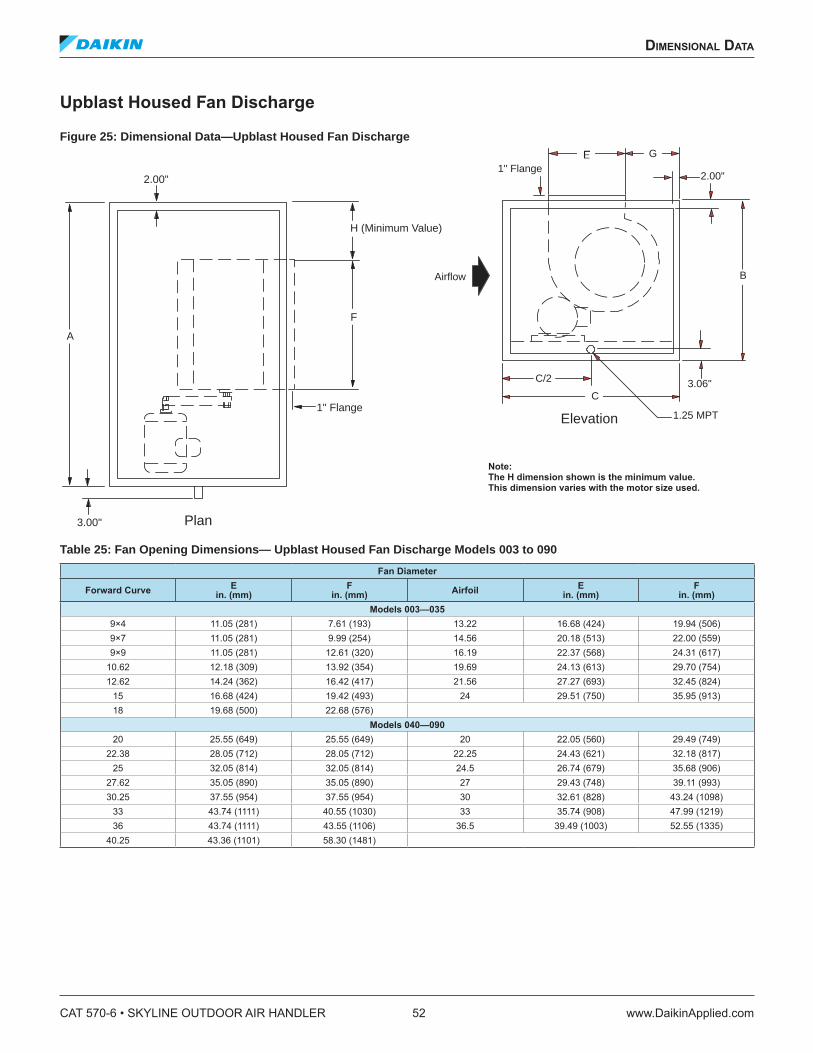
Upblast Housed Fan Discharge
Figure 25: Dimensional Data—Upblast Housed Fan Discharge
Table 25: Fan Opening Dimensions— Upblast Housed Fan Discharge Models 003 to 090
Fan Diameter
Forward CurveE
in. (mm)F
in. (mm) AirfoilE
in. (mm)F
in. (mm)Models 003—035
9×4 11.05 (281) 7.61 (193) 13.22 16.68 (424) 19.94 (506)9×7 11.05 (281) 9.99 (254) 14.56 20.18 (513) 22.00 (559)9×9 11.05 (281) 12.61 (320) 16.19 22.37 (568) 24.31 (617)
10.62 12.18 (309) 13.92 (354) 19.69 24.13 (613) 29.70 (754)12.62 14.24 (362) 16.42 (417) 21.56 27.27 (693) 32.45 (824)
15 16.68 (424) 19.42 (493) 24 29.51 (750) 35.95 (913)18 19.68 (500) 22.68 (576)
Models 040—090
20 25.55 (649) 25.55 (649) 20 22.05 (560) 29.49 (749)22.38 28.05 (712) 28.05 (712) 22.25 24.43 (621) 32.18 (817)
25 32.05 (814) 32.05 (814) 24.5 26.74 (679) 35.68 (906)27.62 35.05 (890) 35.05 (890) 27 29.43 (748) 39.11 (993)30.25 37.55 (954) 37.55 (954) 30 32.61 (828) 43.24 (1098)
33 43.74 (1111) 40.55 (1030) 33 35.74 (908) 47.99 (1219)36 43.74 (1111) 43.55 (1106) 36.5 39.49 (1003) 52.55 (1335)
40.25 43.36 (1101) 58.30 (1481)
Airflow
Elevation 1.25 MPT
3.06"C/2
C
1" FlangeG
2.00"
B
2.00"
3.00"
1" Flange
Plan
A
H (Minimum Value)
F
Note: The H dimension shown is the minimum value. This dimension varies with the motor size used.
CAT 570-6 • SKYLINE OUTDOOR AIR HANDLER 52 www.DaikinApplied.com
dimensional daTa
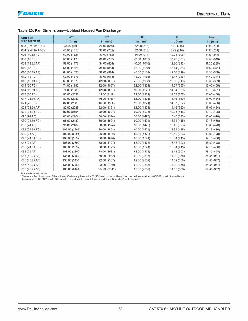
Table 26: Fan Dimensions—Upblast Housed Fan Discharge
Unit Size (Fan Diameter)
A** B** C G H (min)in. (mm) in. (mm) in. (mm) in. (mm) in. (mm)
003 (9×4, 9×7 FC)* 38.00 (965) 26.00 (660) 32.00 (813) 8.49 (216) 8.18 (208)004 (9×7, 9×9 FC)* 40.00 (1016) 30.00 (762) 32.00 (813) 8.49 (216) 8.18 (208)006 (10.62 FC)* 52.00 (1321) 30.00 (762) 36.00 (914) 12.03 (306) 9.43 (240)008 (15 FC) 58.00 (1473) 30.00 (762) 42.00 (1067) 13.76 (350) 12.50 (318)008 (13.22 AF) 58.00 (1473) 34.00 (864) 40.00 (1016) 12.30 (312) 11.25 (286)010 (18 FC) 64.00 (1626) 34.00 (864) 46.00 (1168) 15.14 (385) 14.62 (371)010 (16.19 AF) 64.00 (1626) 36.00 (914) 46.00 (1168) 12.56 (319) 13.33 (339)012 (18 FC) 66.00 (1676) 36.00 (914) 46.00 (1168) 15.17 (385) 14.62 (371)012 (16.19 AF) 66.00 (1676) 42.00 (1067) 46.00 (1168) 12.56 (319) 13.33 (339)014 (20 FC) 74.00 (1880) 42.00 (1067) 52.00 (1321) 14.07 (357) 16.00 (406)014 (19.69 AF) 74.00 (1880) 42.00 (1067) 50.00 (1270) 14.54 (369) 15.78 (401)017 (20 FC) 80.00 (2032) 42.00 (1118) 52.00 (1321) 14.07 (357) 16.00 (406)017 (21.56 AF) 80.00 (2032) 46.00 (1168) 52.00 (1321) 14.16 (360) 17.09 (434)021 (20 FC) 82.00 (2083) 46.00 (1168) 52.00 (1321) 14.07 (357) 16.00 (406)021 (21.56 AF) 82.00 (2083) 52.00 (1321) 52.00 (1321) 14.16 (360) 17.09 (434)025 (24.50 FC)* 86.00 (2184) 52.00 (1321) 60.00 (1524) 16.34 (415) 19.15 (486)025 (24 AF) 86.00 (2184) 60.00 (1524) 58.00 (1473) 15.48 (393) 18.80 (478)030 (24.50 FC) 98.00 (2489) 60.00 (1524) 60.00 (1524) 16.34 (415) 19.15 (486)030 (24 AF) 98.00 (2489) 60.00 (1524) 58.00 (1473) 15.48 (393) 18.80 (478)035 (24.50 FC) 102.00 (2591) 60.00 (1524) 60.00 (1524) 16.34 (415) 19.15 (486)035 (24 AF) 102.00 (2591) 66.00 (1676) 58.00 (1473) 15.48 (393) 18.80 (478)045 (24.50 FC) 106.00 (2692) 66.00 (1676) 60.00 (1524) 16.34 (415) 19.15 (486)045 (24 AF) 106.00 (2692) 68.00 (1727) 58.00 (1473) 15.48 (393) 18.80 (478)055 (24.50 FC) 106.00 (2692) 68.00 (1727) 60.00 (1524) 16.34 (415) 19.15 (486)055 (24 AF) 106.00 (2692) 78.00 (1981) 58.00 (1473) 15.48 (393) 18.80 (478)065 (40.25 AF) 136.00 (3454) 80.00 (2032) 92.00 (2337) 14.09 (358) 34.85 (987)080 (40.25 AF) 136.00 (3454) 92.00 (2337) 92.00 (2337) 14.09 (358) 34.85 (987)085 (40.25 AF) 136.00 (3454) 98.00 (2489) 92.00 (2337) 14.09 (358) 34.85 (987)090 (40.25 AF) 136.00 (3454) 104.00 (2641) 92.00 (2337) 14.09 (358) 34.85 (987)
* Not available with vanes. ** These are the dimensions of the unit only Curb-ready base adds 6" (152 mm) to the unit height. A standard base rail adds 8" (203 mm) to the width, and between 4" to 12" (102 mm to 305 mm) to the unit height.Height dimension does not include 2" roof cap seam.
dimensional daTa
www.DaikinApplied.com 53 CAT 570-6 • SKYLINE OUTDOOR AIR HANDLER

Fan Array
Figure 26: Dimensional Data—Fan Array Four Fan Model
Table 27: Coniguration Dimensions—Fan Array
Fan Coniguration Wheel Size in. (mm)
DL in. (mm)
FL in. (mm)
AL in. (mm)
H in. (mm)
W in. (mm)
1×3
12 (304.8) 14 (355.6) 28 (711.2) 24 (609.6) 36 (914.4) 104 (2641.6)15 (381) 14 (355.6) 32 (812.8) 24 (609.6) 38 (965.2) 110 (2794)
18 (457.2) 14 (355.6) 40 (1016) 24 (609.6) 44 (1117.6) 128 (3251.2)20 (508) 14 (355.6) 42 (1066.8) 24 (609.6) 46 (1168.4) 140 (3556)
22 (558.8) 14 (355.6) 42 (1066.8) 24 (609.6) 50 (1270) 146 (3708.4)24 (609.6) 14 (355.6) 46 (1168.4) 24 (609.6) 52 (1320.8) 158 (4013.2)27 (685.8) 14 (355.6) 48 (1219.2) 30 (762) 56 (1422.4) 170 (4318)30 (762) 14 (355.6) 54 (1371.6) 30 (762) 60 (1524) 182 (4622.8)
33 (838.2) 14 (355.6) 54 (1371.6) 30 (762) 60 (1524) 182 (4622.8)
2×2
12 (304.8) 14 (355.6) 28 (711.2) 24 (609.6) 68 (1727.2) 70 (1778)15 (381) 14 (355.6) 32 (812.8) 24 (609.6) 72 (1828.8) 74 (1879.6)
18 (457.2) 14 (355.6) 40 (1016) 24 (609.6) 84 (2133.6) 86 (2184.4)20 (508) 14 (355.6) 42 (1066.8) 24 (609.6) 88 (2235.2) 94 (2387.6)
22 (558.8) 14 (355.6) 42 (1066.8) 24 (609.6) 96 (2438.4) 98 (2489.2)24 (609.6) 14 (355.6) 46 (1168.4) 24 (609.6) 100 (2540) 106 (2692.4)27 (685.8) 14 (355.6) 48 (1219.2) 30 (762) 108 (2743.2) 114 (2895.6)30 (762) 14 (355.6) 54 (1371.6) 30 (762) 116 (2946.4) 122 (3098.8)
33 (838.2) 14 (355.6) 54 (1371.6) 30 (762) 116 (2946.4) 122 (3098.8)
2×3
12 (304.8) 14 (355.6) 28 (711.2) 24 (609.6) 68 (1727.2) 104 (2641.6)15 (381) 14 (355.6) 32 (812.8) 24 (609.6) 72 (1828.8) 110 (2794)
18 (457.2) 14 (355.6) 40 (1016) 24 (609.6) 84 (2133.6) 128 (3251.2)20 (508) 14 (355.6) 42 (1066.8) 24 (609.6) 88 (2235.2) 140 (3556)
22 (558.8) 14 (355.6) 42 (1066.8) 24 (609.6) 96 (2438.4) 146 (3708.4)24 (609.6) 14 (355.6) 46 (1168.4) 24 (609.6) 100 (2540) 158 (4013.2)27 (685.8) 14 (355.6) 48 (1219.2) 30 (762) 108 (2743.2) 170 (4318)30 (762) 14 (355.6) 54 (1371.6) 30 (762) 116 (2946.4) 182 (4622.8)
33 (838.2) 14 (355.6) 54 (1371.6) 30 (762) 116 (2946.4) 182 (4622.8)Note: Other conigurations available. Consult local Daikin sales representative for selection
* Minimum dimensions may relect a variable geometric aspect ratio. Use the next size larger width or height for a standard aspect ratio.
ALDL
H
FL
W
Plan Elevation
CAT 570-6 • SKYLINE OUTDOOR AIR HANDLER 54 www.DaikinApplied.com
dimensional daTa
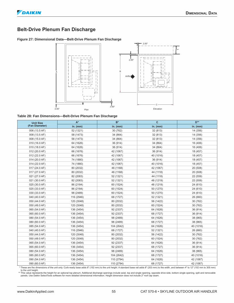
Belt-Drive Plenum Fan Discharge
Figure 27: Dimensional Data—Belt-Drive Plenum Fan Discharge
Table 28: Fan Dimensions—Belt-Drive Plenum Fan Discharge
Unit Size (Fan Diameter)
A* B* C D**
in. (mm) in. (mm) in. (mm) in. (mm)006 (13.5 AF) 52 (1321) 30 (762) 32 (813) 14 (356)008 (13.5 AF) 58 (1473) 34 (864) 32 (813) 14 (356)008 (15.0 AF) 58 (1473) 34 (864) 32 (813) 14 (356)010 (16.0 AF) 64 (1626) 36 (914) 34 (864) 16 (406)010 (18.0 AF) 64 (1626) 36 (914) 34 (864) 16 (406)012 (20.0 AF) 66 (1676) 42 (1067) 36 (914) 18 (457)012 (22.0 AF) 66 (1676) 42 (1067) 40 (1016) 18 (457)014 (20.0 AF) 74 (1880) 42 (1067) 36 (914) 18 (457)014 (22.0 AF) 74 (1880) 42 (1067) 40 (1016) 18 (457)017 (24.0 AF) 80 (2032) 46 (1168) 42 (1067) 20 (508)017 (27.0 AF) 80 (2032) 46 (1168) 44 (1118) 20 (508)021 (27.0 AF) 82 (2083) 52 (1321) 44 (1118) 22 (559)021 (30.0 AF) 82 (2083) 52 (1321) 48 (1219) 22 (559)025 (30.0 AF) 86 (2184) 60 (1524) 48 (1219) 24 (610)025 (33.0 AF) 86 (2184) 60 (1524) 50 (1270) 24 (610)030 (33.0 AF) 98 (2489) 60 (1524) 50 (1270) 24 (610)040 (40.0 AF) 116 (2946) 68 (1727) 52 (1321) 26 (660)050 (44.0 AF) 120 (3048) 80 (2032) 56 (1422) 30 (762)050 (49.0 AF) 120 (3048) 80 (2032) 60 (1524) 30 (762)065 (54.0 AF) 136 (3454) 92 (2337) 64 (1626) 36 (914)065 (60.0 AF) 136 (3454) 92 (2337) 68 (1727) 36 (914)080 (54.0 AF) 136 (3454) 98 (2489) 64 (1626) 38 (965)080 (60.0 AF) 136 (3454) 98 (2489) 68 (1727) 38 (965)085 (54.0 AF) 136 (3454) 104 (2642) 64 (1626) 40 (1016)040 (40.0 AF) 116 (2946) 68 (1727) 52 (1321) 26 (660)050 (44.0 AF) 120 (3048) 80 (2032) 56 (1422) 30 (762)050 (49.0 AF) 120 (3048) 80 (2032) 60 (1524) 30 (762)065 (54.0 AF) 136 (3454) 92 (2337) 64 (1626) 36 (914)065 (60.0 AF) 136 (3454) 92 (2337) 68 (1727) 36 (914)080 (54.0 AF) 136 (3454) 98 (2489) 64 (1626) 38 (965)085 (60.0 AF) 136 (3454) 104 (2642) 68 (1727) 40 (1016)090 (54.0 AF) 136 (3454) 110 (2794) 64 (1626) 42 (1067)090 (60.0 AF) 136 (3454) 110 (2794) 68 (1727) 42 (1067)
* These are the dimensions of the unit only. Curb-ready base adds 6" (152 mm) to the unit height. A standard base rail adds 8" (203 mm) to the width, and between 4" to 12" (102 mm to 305 mm) to the unit height.
** This value represents the height for an optional top plenum. Additional discharge openings include axial, top and single opening, opposite drive side, bottom single opening, split and removable panels. Use Daikin SelectTools software for more detailed dimensional information. Height dimension does not include 2" roof cap seam.
B
2.00"
2.00"
Airflow
2.00"C
Elevation3.00" Plan
A
D**
dimensional daTa
www.DaikinApplied.com 55 CAT 570-6 • SKYLINE OUTDOOR AIR HANDLER

Direct-Drive Plenum Fan Discharge
Figure 28: Dimensional Data—Direct-Drive Plenum Fan Discharge
Table 29: Fan Dimensions—Direct-Drive Plenum Fan
Unit Size (Fan Diameter)A* B* C**
in. (mm) in. (mm) in. (mm)004 (11 AF) 40 (1016) 30 (762) 28 (711)004 (12 AF) 40 (1016) 30 (762) 30 (762)006 (12 AF) 52 (1321) 30 (762) 30 (762)006 (15 AF) 52 (1321) 30 (762) 34 (864)008 (15 AF) 58 (1473) 34 (864) 34 (864)008 (16 AF) 58 (1473) 34 (864) 40 (1016)010 (16 AF) 64 (1626) 36 (914) 40 (1016)010 (18 AF) 64 (1626) 36 (914) 44 (1118)012 20 AF) 66 (1676) 42 (1067) 44 (1118)012 (22 AF) 66 (1676) 42 (1067) 46 (1168)014 20 AF) 74 (1880) 42 (1067) 44 (1118)014 (22 AF) 74 (1880) 42 (1067) 46 (1168)017 (24 AF) 80 (2032) 46 (1168) 50 (1270)017 (27 AF) 80 (2032) 46 (1168) 56 (1422)021 (27 AF) 82 (2083) 52 (1321) 56 (1422)021 (30 AF) 82 (2083) 52 (1321) 56 (1422)025 (30 AF) 86 (2184) 60 (1524) 56 (1422)025 (36 AF) 68 (1727) 60 (1524) 62 (1575)030 (30 AF) 98 (2489) 60 (1524) 56 (1422)030 (36 AF) 98 (2489) 60 (1524) 62 (1575)035 (33 AF) 102 (2591) 66 (1676) 60 (1524)035 (36 AF) 102 (2591) 66 (1676) 62 (1575)040 (36 AF) 116 (2946) 68 (1727) 62 (1575)040 (40 AF) 116 (2946) 68 (1727) 70 (1778)050 (44 AF) 120 (3048) 80 (2032) 74 (1880)065 (44 AF) 136 (3454) 92 (2337) 74 (1880)080 (44 AF) 136 (3454) 98 (2489) 74 (1880)085 (44 AF) 136 (3454) 104 (2642) 74 (1880)090 (44 AF) 136 (3454) 110 (2794) 74 (1880)
* These are the dimensions of the unit only. A standard base rail adds 8" (203 mm) to the width, and between 4" to 12" (102 mm to 305 mm) to the unit height. A 6" (152 mm) base rail is manda-tory on unit sizes 025 to 065. An 8" (203 mm) base rail is mandatory on unit sizes 080 and larger.
** This value is dependent on motor frame size.
A
B
2.00"
2.00"
Airflow
2.00"
C
Elevation3.00" Plan
2.00"
CAT 570-6 • SKYLINE OUTDOOR AIR HANDLER 56 www.DaikinApplied.com
dimensional daTa
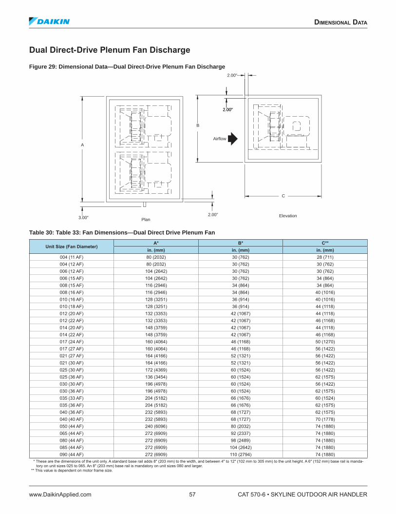
Dual Direct-Drive Plenum Fan Discharge
Figure 29: Dimensional Data—Dual Direct-Drive Plenum Fan Discharge
Table 30: Table 33: Fan Dimensions—Dual Direct Drive Plenum Fan
Unit Size (Fan Diameter)A* B* C**
in. (mm) in. (mm) in. (mm)004 (11 AF) 80 (2032) 30 (762) 28 (711)004 (12 AF) 80 (2032) 30 (762) 30 (762)006 (12 AF) 104 (2642) 30 (762) 30 (762)006 (15 AF) 104 (2642) 30 (762) 34 (864)008 (15 AF) 116 (2946) 34 (864) 34 (864)008 (16 AF) 116 (2946) 34 (864) 40 (1016)010 (16 AF) 128 (3251) 36 (914) 40 (1016)010 (18 AF) 128 (3251) 36 (914) 44 (1118)012 (20 AF) 132 (3353) 42 (1067) 44 (1118)012 (22 AF) 132 (3353) 42 (1067) 46 (1168)014 (20 AF) 148 (3759) 42 (1067) 44 (1118)014 (22 AF) 148 (3759) 42 (1067) 46 (1168)017 (24 AF) 160 (4064) 46 (1168) 50 (1270)017 (27 AF) 160 (4064) 46 (1168) 56 (1422)021 (27 AF) 164 (4166) 52 (1321) 56 (1422)021 (30 AF) 164 (4166) 52 (1321) 56 (1422)025 (30 AF) 172 (4369) 60 (1524) 56 (1422)025 (36 AF) 136 (3454) 60 (1524) 62 (1575)030 (30 AF) 196 (4978) 60 (1524) 56 (1422)030 (36 AF) 196 (4978) 60 (1524) 62 (1575)035 (33 AF) 204 (5182) 66 (1676) 60 (1524)035 (36 AF) 204 (5182) 66 (1676) 62 (1575)040 (36 AF) 232 (5893) 68 (1727) 62 (1575)040 (40 AF) 232 (5893) 68 (1727) 70 (1778)050 (44 AF) 240 (6096) 80 (2032) 74 (1880)065 (44 AF) 272 (6909) 92 (2337) 74 (1880)080 (44 AF) 272 (6909) 98 (2489) 74 (1880)085 (44 AF) 272 (6909) 104 (2642) 74 (1880)090 (44 AF) 272 (6909) 110 (2794) 74 (1880)
* These are the dimensions of the unit only. A standard base rail adds 8" (203 mm) to the width, and between 4" to 12" (102 mm to 305 mm) to the unit height. A 6" (152 mm) base rail is manda-tory on unit sizes 025 to 065. An 8" (203 mm) base rail is mandatory on unit sizes 080 and larger.
** This value is dependent on motor frame size.
A
B
2.00"
2.00"
Airflow
2.00"
C
Elevation3.00" Plan
2.00"
dimensional daTa
www.DaikinApplied.com 57 CAT 570-6 • SKYLINE OUTDOOR AIR HANDLER
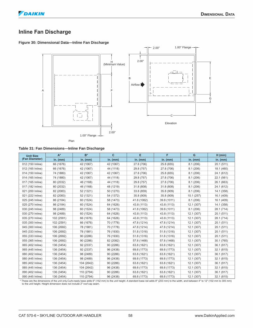
Inline Fan Discharge
Figure 30: Dimensional Data—Inline Fan Discharge
Table 31: Fan Dimensions—Inline Fan Discharge
Unit Size (Fan Diameter)
A* B* C E F G H (min)in. (mm) in. (mm) in. (mm) in. (mm) in. (mm) in. (mm) in. (mm)
012 (150 Inline) 66 (1676) 42 (1067) 42 (1067) 27.8 (706) 25.8 (655) 8.1 (206) 20.1 (511)012 (165 Inline) 66 (1676) 42 (1067) 44 (1118) 29.8 (757) 27.8 (706) 8.1 (206) 18.1 (460)014 (150 Inline) 74 (1880) 42 (1067) 42 (1067) 27.8 (706) 25.8 (655) 8.1 (206) 24.1 (612)014 (165 Inline) 74 (1880) 42 (1067) 44 (1118) 29.8 (757) 27.8 (706) 8.1 (206) 22.1 (561)017 (165 Inline) 80 (2032) 46 (1168) 44 (1118) 29.8 (757) 27.8 (706) 8.1 (206) 26.1 (663)017 (182 Inline) 80 (2032) 46 (1168) 48 (1219) 31.8 (808) 31.8 (808) 8.1 (206) 24.1 (612)021 (200 Inline) 82 (2083) 52 (1321) 50 (1270) 33.8 (859) 35.8 (909) 8.1 (206) 14.1 (358)021 (222 Inline) 82 (2083) 52 (1321) 54 (1372) 35.8 (909) 35.8 (909) 10.1 (257) 16.1 (409)025 (245 Inline) 86 (2184) 60 (1524) 58 (1473) 41.8 (1062) 39.8 (1011) 8.1 (206) 16.1 (409)025 (270 Inline) 86 (2184) 60 (1524) 64 (1626) 43.8 (1113) 43.8 (1113) 12.1 (307) 14.1 (358)030 (245 Inline) 98 (2489) 60 (1524) 58 (1473) 41.8 (1062) 39.8 (1011) 8.1 (206) 28.1 (714)030 (270 Inline) 98 (2489) 60 (1524) 64 (1626) 43.8 (1113) 43.8 (1113) 12.1 (307) 20.1 (511)035 (270 Inline) 102 (2591) 66 (1676) 64 (1626) 43.8 (1113) 43.8 (1113) 12.1 (307) 28.1 (714)035 (300 Inline) 102 (2591) 66 (1676) 70 (1778) 47.8 (1214) 47.8 (1214) 12.1 (307) 20.1 (511)045 (300 Inline) 106 (2692) 78 (1981) 70 (1778) 47.8 (1214) 47.8 (1214) 12.1 (307) 20.1 (511)045 (333 Inline) 106 (2692) 78 (1981) 76 (1930) 51.8 (1316) 51.8 (1316) 12.1 (307) 20.1 (511)055 (333 Inline) 106 (2692) 90 (2286) 76 (1930) 51.8 (1316) 51.8 (1316) 12.1 (307) 20.1 (511)055 (365 Inline) 106 (2692) 90 (2286) 82 (2082) 57.8 (1468) 57.8 (1468) 12.1 (307) 30.1 (765)065 (402 Inline) 136 (3454) 92 (2337) 90 (2286) 63.8 (1621) 63.8 (1621) 12.1 (307) 36.1 (917)065 (445 Inline) 136 (3454) 92 (2337) 96 (2438) 69.8 (1773) 69.8 (1773) 12.1 (307) 32.1 (815)080 (402 Inline) 136 (3454) 98 (2489) 90 (2286) 63.8 (1621) 63.8 (1621) 12.1 (307) 36.1 (917)080 (445 Inline) 136 (3454) 98 (2489) 96 (2438) 69.8 (1773) 69.8 (1773) 12.1 (307) 32.1 (815)085 (402 Inline) 136 (3454) 104 (2642) 90 (2286) 63.8 (1621) 63.8 (1621) 12.1 (307) 36.1 (917)085 (445 Inline) 136 (3454) 104 (2642) 96 (2438) 69.8 (1773) 69.8 (1773) 12.1 (307) 32.1 (815)090 (402 Inline) 136 (3454) 110 (2794) 90 (2286) 63.8 (1621) 63.8 (1621) 12.1 (307) 36.1 (917)090 (445 Inline) 136 (3454) 110 (2794) 96 (2438) 69.8 (1773) 69.8 (1773) 12.1 (307) 32.1 (815)
* These are the dimensions of the unit only.Curb-ready base adds 6" (152 mm) to the unit height. A standard base rail adds 8" (203 mm) to the width, and between 4" to 12" (102 mm to 305 mm) to the unit height. Height dimension does not include 2" roof cap seam.
A
2.00"
2.00"
Airflow
2.00"
C
Elevation
1.00" Flange
Plan
E
G
1.00" Flange
H(Minimum Value)
F
B
CAT 570-6 • SKYLINE OUTDOOR AIR HANDLER 58 www.DaikinApplied.com
dimensional daTa

Cooling Coil Section
The single cooling coil section is available in numerous depths. This provides the option of varying the amount of space downstream from the coil for access to inspect and clean the coil and drain pan. When using a single bank of coils, the 18" deep section holds up to a 4-row water or DX coil.
Also available are staggered cooling coils. The staggered arrangement maximizes the cooling coil face area by providing two banks of coils. These two coils are not stacked, but are
staggered in the direction of airlow. This coniguration does require more section depth in the direction of airlow. Staggered coils are only available on unit sizes 025 and larger. The section depth required varies between 30" to 54". This depends on the unit size and number of rows in the coil.
Standard base units require a minimum cooling coil vestibule length of 12". Curb-ready base units require a minimum cooling coil vestibule length of 18".
Figure 31: Dimensional Data—Cooling Coil Section
Table 32: Dimensions—Cooling Coil Section
Unit Size A (Large, Medium Coils)* A (Extended Coils)* B* C (Available All Sizes)**
in. (mm) in. (mm) in. (mm) in. (mm)003 38 (965) 44 (1118) 26 (660)
18.0 (457) to
54.0 (1372)In 2ʺ increments
004 40 (1016) 46 (1168) 30 (762)006 52 (1321) 58 (1473) 30 (762)008 58 (1473) 64 (1626) 34 (864)010 64 (1626) 70 (1778) 36 (914)012 66 (1676) 72 (1829) 42 (1067)014 74 (1880) 80 (2032) 42 (1067)017 80 (2032) 86 (2184) 46 (1168)021 82 (2083) 88 (2235) 52 (1321)025 86 (2184) N/A 60 (1524)030 98 (2489) N/A 60 (1524)035 102 (2591) N/A 66 (1676)045 106 (2692) N/A 78 (1981)055 106 (2692) N/A 90 (2286)065 136 (3454) N/A 92 (2337)080 136 (3454) N/A 98 (2489)085 136 (3454) N/A 104 (2642)090 136 (3454) N/A 110 (2794)
* These are the dimensions of the unit only. Curb-ready base adds 6" (152 mm) to the unit height. A standard base rail adds 8" (203 mm) to the width, and between 4" to 12" (102 mm to 305 mm) to the unit height
** All cooling coil lengths listed are available for any unit size (003 to 055). Height dimension does not include 2" roof cap seam.
Airflow
Plan
Elevation
2.00"
A
6.00" - 8.00"approx.
3.00"
2.00"
C
B
3.00" 2.00"
C/2 Drain Conn.*1.25 MPT
dimensional daTa
www.DaikinApplied.com 59 CAT 570-6 • SKYLINE OUTDOOR AIR HANDLER

Combination Cooling and Reheat Coil Section
The combination cooling and reheat coil section is available in numerous depths. This provides the option of varying the amount of space between the cooling coil and reheat coil for access to inspect and clean the coil and drain pan. All reheat and most cooling coils are arranged in a single bank, which can be 1, 2 or 3 coils high. When using a single bank of cooling coils, the 24" deep section holds up to a 4-row water or DX coil, and a 1-row or 2-row heating coil. A 36" deep section holds a 12-row water coil and a 1 or 2-row reheat coil.
Also available are staggered cooling coils. The staggered arrangement maximizes the cooling coil face area by providing
two banks of coils. These two coils are not stacked, but are staggered in the direction of airlow. This coniguration does require more section depth in the direction of airlow. Staggered coils are available only on unit sizes 025 and larger. The section depth required varies between 30" to 54". This depends on the unit size and number of rows in the coil.
Standard base units require a minimum combination coil vestibule length of 12". Curb-ready base units require a minimum combination coil length of 16" and a minimum coil vestibule length of 18".
Figure 32: Dimensional Data—Combination Cooling and Reheat Coil Section
Table 33: Table 36: Dimensions—Combination Cooling and Reheat Coil
Unit Size A (Large, Medium Coils)* A (Extended Coils)* B* C (Available All Sizes)**in. (mm) in. (mm) in. (mm) in. (mm)
003 38 (965) 44 (1118) 26 (660)
18.0 (457) to
54.0 (1372)In 2ʺ increments
004 40 (1016) 46 (1168) 30 (762)006 52 (1321) 58 (1473) 30 (762)008 58 (1473) 64 (1626) 34 (864)010 64 (1626) 70 (1778) 36 (914)012 66 (1676) 72 (1829) 42 (1067)014 74 (1880) 80 (2032) 42 (1067)017 80 (2032) 86 (2184) 46 (1168)021 82 (2083) 88 (2235) 52 (1321)025 86 (2184) N/A 60 (1524)030 98 (2489) N/A 60 (1524)035 102 (2591) N/A 66 (1676)045 106 (2692) N/A 78 (1981)055 106 (2692) N/A 90 (2286)065 136 (3454) N/A 92 (2337)080 136 (3454) N/A 98 (2489)085 136 (3454) N/A 104 (2642)090 136 (3454) N/A 110 (2794)
* These are the dimensions of the unit only. Curb-ready base adds 6" (152 mm) to the unit height. A standard base rail adds 8" (203 mm) to the width, and between 4" to 12" (102 mm to 305 mm) to the unit height
** All cooling coil lengths listed are available for any unit size (003 to 055). Height dimension does not include 2" roof cap seam.
Airflow
Plan
Elevation
2.00"
A
6.00" - 8.00"approx.
3.00"
2.00"
C
B
3.00" 2.00"
C/2 Drain Conn.*1.25 MPT
CAT 570-6 • SKYLINE OUTDOOR AIR HANDLER 60 www.DaikinApplied.com
dimensional daTa
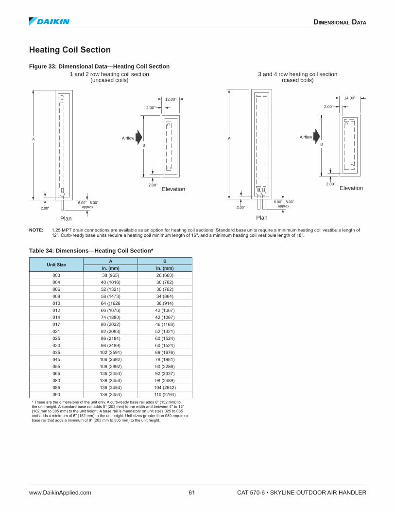
Heating Coil Section
Figure 33: Dimensional Data—Heating Coil Section
NOTE: 1.25 MPT drain connections are available as an option for heating coil sections. Standard base units require a minimum heating coil vestibule length of 12". Curb-ready base units require a heating coil minimum length of 16", and a minimum heating coil vestibule length of 18".
Table 34: Dimensions—Heating Coil Section*
Unit Size A B
in. (mm) in. (mm)003 38 (965) 26 (660)004 40 (1016) 30 (762)006 52 (1321) 30 (762)008 58 (1473) 34 (864)010 64 ()1626 36 (914)012 66 (1676) 42 (1067)014 74 (1880) 42 (1067)017 80 (2032) 46 (1168)021 82 (2083) 52 (1321)025 86 (2184) 60 (1524)030 98 (2489) 60 (1524)035 102 (2591) 66 (1676)045 106 (2692) 78 (1981)055 106 (2692) 90 (2286)065 136 (3454) 92 (2337)080 136 (3454) 98 (2489)085 136 (3454) 104 (2642)090 136 (3454) 110 (2794)
* These are the dimensions of the unit only. A curb-ready base rail adds 6" (152 mm) to the unit height. A standard base rail adds 8" (203 mm) to the width and between 4" to 12" (102 mm to 305 mm) to the unit height. A base rail is mandatory on unit sizes 025 to 065 and adds a minimum of 6" (152 mm) to the unitheight. Unit sizes greater than 080 require a base rail that adds a minimum of 8" (203 mm to 305 mm) to the unit height.
Plan
6.00" - 8.00"approx.2.00"
A Airflow
B
Elevation
12.00"
2.00"
2.00"
Airflow
B
Elevation
14.00"
2.00"
2.00"
Plan
6.00" - 8.00"approx.2.00"
A
3 and 4 row heating coil section(cased coils)
1 and 2 row heating coil section(uncased coils)
dimensional daTa
www.DaikinApplied.com 61 CAT 570-6 • SKYLINE OUTDOOR AIR HANDLER
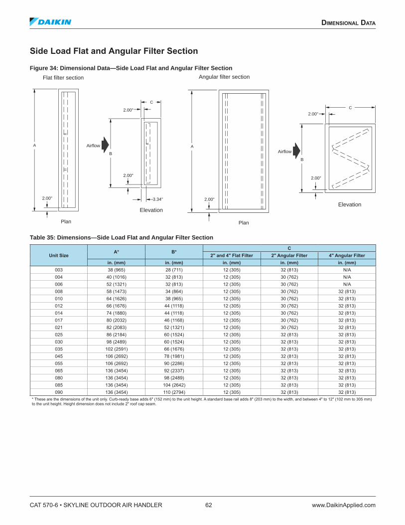
Side Load Flat and Angular Filter Section
Figure 34: Dimensional Data—Side Load Flat and Angular Filter Section
Table 35: Dimensions—Side Load Flat and Angular Filter Section
Unit SizeA* B*
C
2" and 4" Flat Filter 2" Angular Filter 4" Angular Filter
in. (mm) in. (mm) in. (mm) in. (mm) in. (mm)003 38 (965) 28 (711) 12 (305) 32 (813) N/A004 40 (1016) 32 (813) 12 (305) 30 (762) N/A006 52 (1321) 32 (813) 12 (305) 30 (762) N/A008 58 (1473) 34 (864) 12 (305) 30 (762) 32 (813)010 64 (1626) 38 (965) 12 (305) 30 (762) 32 (813)012 66 (1676) 44 (1118) 12 (305) 30 (762) 32 (813)014 74 (1880) 44 (1118) 12 (305) 30 (762) 32 (813)017 80 (2032) 46 (1168) 12 (305) 30 (762) 32 (813)021 82 (2083) 52 (1321) 12 (305) 30 (762) 32 (813)025 86 (2184) 60 (1524) 12 (305) 32 (813) 32 (813)030 98 (2489) 60 (1524) 12 (305) 32 (813) 32 (813)035 102 (2591) 66 (1676) 12 (305) 32 (813) 32 (813)045 106 (2692) 78 (1981) 12 (305) 32 (813) 32 (813)055 106 (2692) 90 (2286) 12 (305) 32 (813) 32 (813)065 136 (3454) 92 (2337) 12 (305) 32 (813) 32 (813)080 136 (3454) 98 (2489) 12 (305) 32 (813) 32 (813)085 136 (3454) 104 (2642) 12 (305) 32 (813) 32 (813)090 136 (3454) 110 (2794) 12 (305) 32 (813) 32 (813)
* These are the dimensions of the unit only. Curb-ready base adds 6" (152 mm) to the unit height. A standard base rail adds 8" (203 mm) to the width, and between 4" to 12" (102 mm to 305 mm) to the unit height. Height dimension does not include 2" roof cap seam.
Plan
A Airflow
B
Elevation
Flat filter section
C
2.00"
2.00"
3.34"2.00"
Angular filter section
Plan
2.00"
A
2.00"
Airflow
B
C
Elevation
2.00"
CAT 570-6 • SKYLINE OUTDOOR AIR HANDLER 62 www.DaikinApplied.com
dimensional daTa
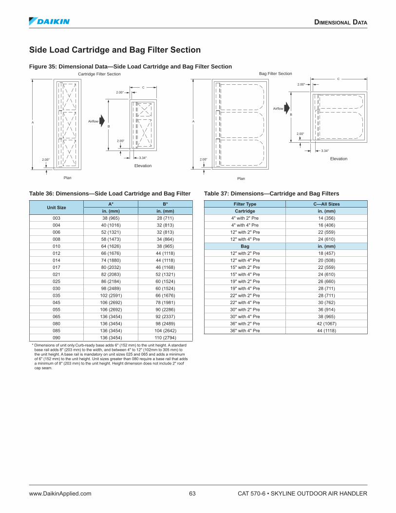
Side Load Cartridge and Bag Filter Section
Figure 35: Dimensional Data—Side Load Cartridge and Bag Filter Section
Table 36: Dimensions—Side Load Cartridge and Bag Filter
Unit SizeA* B*
in. (mm) in. (mm)003 38 (965) 28 (711)004 40 (1016) 32 (813)006 52 (1321) 32 (813)008 58 (1473) 34 (864)010 64 (1626) 38 (965)012 66 (1676) 44 (1118)014 74 (1880) 44 (1118)017 80 (2032) 46 (1168)021 82 (2083) 52 (1321)025 86 (2184) 60 (1524)030 98 (2489) 60 (1524)035 102 (2591) 66 (1676)045 106 (2692) 78 (1981)055 106 (2692) 90 (2286)065 136 (3454) 92 (2337)080 136 (3454) 98 (2489)085 136 (3454) 104 (2642)090 136 (3454) 110 (2794)
* Dimensions of unit only.Curb-ready base adds 6" (152 mm) to the unit height. A standard base rail adds 8" (203 mm) to the width, and between 4" to 12" (102mm to 305 mm) to the unit height. A base rail is mandatory on unit sizes 025 and 065 and adds a minimum of 6" (152 mm) to the unit height. Unit sizes greater than 080 require a base rail that adds a minimum of 8" (203 mm) to the unit height. Height dimension does not include 2" roof cap seam.
Table 37: Dimensions—Cartridge and Bag Filters
Filter Type C—All Sizes
Cartridge in. (mm)4" with 2" Pre 14 (356)4" with 4" Pre 16 (406)
12" with 2" Pre 22 (559)12" with 4" Pre 24 (610)
Bag in. (mm)12" with 2" Pre 18 (457)12" with 4" Pre 20 (508)15" with 2" Pre 22 (559)15" with 4" Pre 24 (610)19" with 2" Pre 26 (660)19" with 4" Pre 28 (711)22" with 2" Pre 28 (711)22" with 4" Pre 30 (762)30" with 2" Pre 36 (914)30" with 4" Pre 38 (965)36" with 2" Pre 42 (1067)36" with 4" Pre 44 (1118)
Plan
A Airflow
B
Elevation
Cartridge Filter Section
C
2.00"
Bag Filter Section
Plan
2.00"
A
Airflow
B
C
Elevation
2.00"
3.34"
2.00"
2.00"
2.00"
3.34"
dimensional daTa
www.DaikinApplied.com 63 CAT 570-6 • SKYLINE OUTDOOR AIR HANDLER

Front Load Cartridge and Bag Filter Section
Figure 36: Dimensional Data—Front Load Cartridge and Bag Filter Section
NOTE: An upstream plenum with tread plate is required on all front load ilter sections.
Table 38: Front Load Cartridge Bag Filter Section
Unit Size A* B*
in. (mm) in. (mm)003 38 (965) 28 (711)004 40 (1016) 32 (813)006 52 (1321) 32 (813)008 58 (1473) 34 (864)010 64 (1626) 38 (965)012 66 (1676) 44 (1118)014 74 (1880) 44 (1118)017 80 (2032) 46 (1168)021 82 (2083) 52 (1321)025 86 (2184) 60 (1524)030 98 (2489) 60 (1524)035 102 (2591) 66 (1676)045 106 (2692) 78 (1981)055 106 (2692) 90 (2286)065 136 (3454) 92 (2337)080 136 (3454) 98 (2489)085 136 (3454) 104 (2642)090 136 (3454) 110 (1795)
* Dimensions of unit only. Curb-ready base adds 6" (152 mm) to the unit height. A standard base rail adds 8" (203 mm) to width and between 4" to12" (102 mm to 305 mm) to unit height. Height dimension does not include 2" roof cap seam.
Table 39: Filter Dimensions
Filter Type C—All Sizes
Cartridge in. (mm)4" with 2" Pre 12 (305)4" with 4" Pre 12 (305)
12" with 2" Pre 16 (406)12" with 4" Pre 16 (406)
Bag in. (mm)12" with 2" Pre 16 (406)12" with 4" Pre 16 (406)15" with 2" Pre 20 (508)15" with 4" Pre 20 (508)19" with 2" Pre 24 (610)19" with 4" Pre 24 (610)22" with 2" Pre 26 (660)22" with 4" Pre 26 (660)30" with 2" Pre 34 (864)30" with 4" Pre 34 (864)36" with 2" Pre 40 (1016)36" with 4" Pre 40 (1016)
Plan
AAirflow B
Elevation
Cartridge filter section
C
2.00"
Bag filter section
Plan
2.00"
AAirflow
B
C
Elevation
2.00"
3.00" (2" Prefilter)5.00" (4" Prefilter)
2.00"
2.00"
2.00"
3.00" (2" Prefilter)5.00" (4" Prefilter)
CAT 570-6 • SKYLINE OUTDOOR AIR HANDLER 64 www.DaikinApplied.com
dimensional daTa
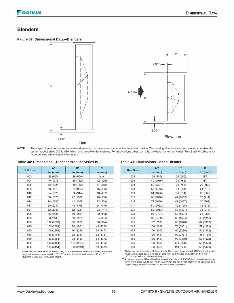
Blenders
Figure 37: Dimensional Data—Blenders
NOTE: The depth of an air mixer section varies depending on components adjacent to the mixing device. The catalog dimensions shown are for a two-blender system except sizes 040 to 090, which are three-blender systems. For applications other than this, the depth dimension varies. Use Skyline software for more detailed dimensional information.
Table 40: Dimensions—Blender Product Series IV
Unit SizeA* B* C
in. (mm) in. (mm) in. (mm)003 38 (965) 26 (660) N/A004 40 (1016) 30 (762) 12 (305)006 52 (1321) 30 (762) 14 (356)008 58 (1473) 34 (864) 16 (406)010 64 (1626) 36 (914) 18 (457)012 66 (1676) 42 (1067) 20 (508)014 74 (1880) 42 (1067) 22 (559)017 80 (2032) 46 (1168) 24 (610)021 82 (2083) 52 (1321) 28 (711)025 86 (2184) 60 (1524) 32 (813)030 98 (2489) 60 (1524) 34 (864)035 102 (2591) 66 (1676) 36 (914)045 106 (2692) 78 (1981) 48 (1219)055 106 (2692) 90 (2286) 58 (1473)065 136 (3454) 92 (2337) 52 (1321)080 136 (3454) 98 (3489) 54 (1372)085 136 (3454) 104 (2642) 56 (1422)090 136 (3454) 110 (2794) 58 (1473)
* These are the dimensions of the unit only. Curb-ready base adds 6" (152 mm) to the unit height. A standard base rail adds 8" (203 mm) to the width, and between 4" to 12" (102 mm to 305 mm) to the unit height.
Table 41: Dimensions—Kees Blender
Unit SizeA** B* C
in. (mm) in. (mm) in. (mm)003 38 (965) 26 (660) N/A004 40 (1016) 30 (762) N/A006 52 (1321) 30 (762) 22 (559)008 58 (1473) 34 (864) 24 (610)010 64 (1626) 36 (914) 26 (660)012 66 (1676) 42 (1067) 28 (711)014 74 (1880) 42 (1067) 30 (762)017 80 (2032) 46 (1168) 32 (813)021 82 (2083) 52 (1321) 36 (914)025 86 (2184) 60 (1524) 38 (965)030 98 (2489) 60 (1524) 40 (1016)035 102 (2591) 66 (1676) 42 (1067)045 106 (2692) 78 (1981) 52 (1321)055 106 (2692) 90 (2286) 54 (1372)065 136 (3454) 92 (2337) 46 (1168)080 136 (3454) 98 (3489) 56 (1422)085 136 (3454) 104 (2642) 58 (1473)090 136 (3454) 110 (2794) 58 (1473)
* These are the dimensions of the unit only. Curb-ready base adds 6" (152 mm) to the unit height. A standard base rail adds 8" (203 mm) to the width, and between 4" to 12" (102 mm to 305 mm) to the unit height.
** All values represent Kees blenders located after ilters. A 6" (152 mm) base rail is manda-tory on unit sizes 025 to 065. An 8" (203 mm) base rail is mandatory on all sizes 080 and larger. Height dimension does not include 2" roof cap seam.
Elevation
Plan
2.00"
A
Airflow
B
C
2.00"
2.00"
dimensional daTa
www.DaikinApplied.com 65 CAT 570-6 • SKYLINE OUTDOOR AIR HANDLER
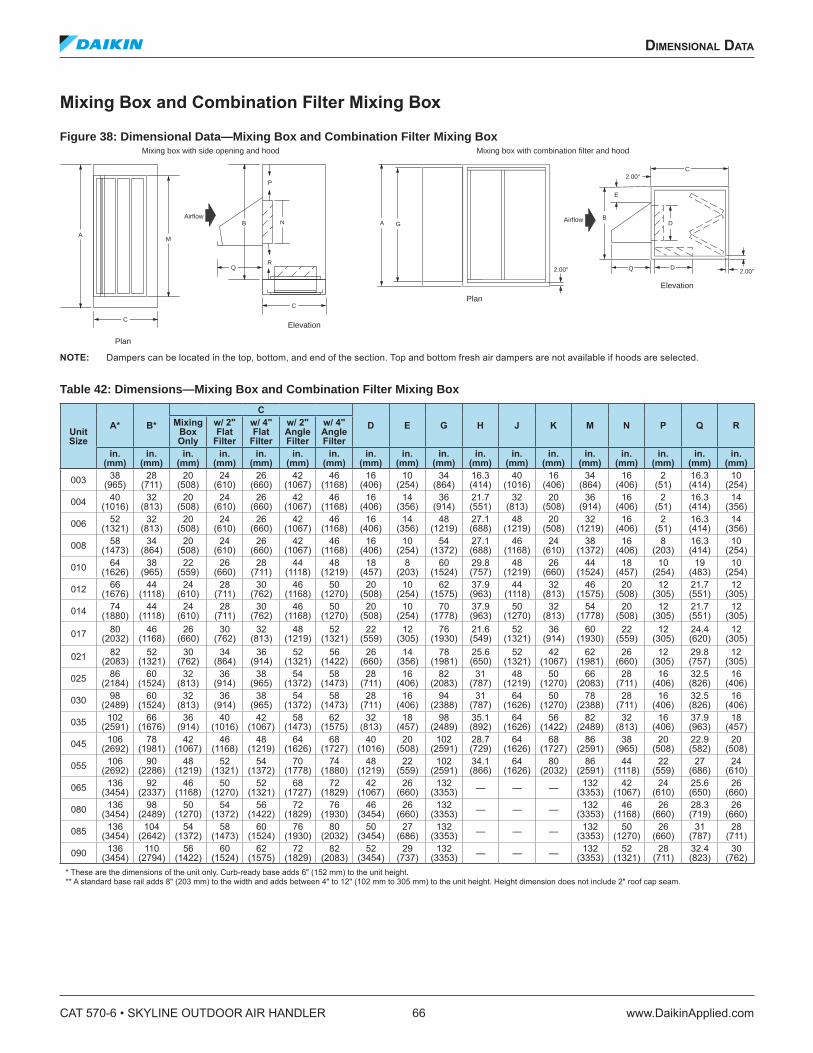
Mixing Box and Combination Filter Mixing Box
Figure 38: Dimensional Data—Mixing Box and Combination Filter Mixing Box
NOTE: Dampers can be located in the top, bottom, and end of the section. Top and bottom fresh air dampers are not available if hoods are selected.
Table 42: Dimensions—Mixing Box and Combination Filter Mixing Box
Unit Size
A* B*
C
D E G H J K M N P Q RMixing Box Only
w/ 2" Flat
Filter
w/ 4" Flat
Filter
w/ 2" Angle Filter
w/ 4" Angle Filter
in. (mm)
in. (mm)
in. (mm)
in. (mm)
in. (mm)
in. (mm)
in. (mm)
in. (mm)
in. (mm)
in. (mm)
in. (mm)
in. (mm)
in. (mm)
in. (mm)
in. (mm)
in. (mm)
in. (mm)
in. (mm)
00338
(965)28
(711)20
(508)24
(610)26
(660)42
(1067)46
(1168)16
(406)10
(254)34
(864)16.3 (414)
40 (1016)
16 (406)
34 (864)
16 (406)
2 (51)
16.3 (414)
10 (254)
00440
(1016)32
(813)20
(508)24
(610)26
(660)42
(1067)46
(1168)16
(406)14
(356)36
(914)21.7 (551)
32 (813)
20 (508)
36 (914)
16 (406)
2 (51)
16.3 (414)
14 (356)
00652
(1321)32
(813)20
(508)24
(610)26
(660)42
(1067)46
(1168)16
(406)14
(356)48
(1219)27.1 (688)
48 (1219)
20 (508)
32 (1219)
16 (406)
2 (51)
16.3 (414)
14 (356)
00858
(1473)34
(864)20
(508)24
(610)26
(660)42
(1067)46
(1168)16
(406)10
(254)54
(1372)27.1 (688)
46 (1168)
24 (610)
38 (1372)
16 (406)
8 (203)
16.3 (414)
10 (254)
01064
(1626)38
(965)22
(559)26
(660)28
(711)44
(1118)48
(1219)18
(457)8
(203)60
(1524)29.8 (757)
48 (1219)
26 (660)
44 (1524)
18 (457)
10 (254)
19 (483)
10 (254)
01266
(1676)44
(1118)24
(610)28
(711)30
(762)46
(1168)50
(1270)20
(508)10
(254)62
(1575)37.9 (963)
44 (1118)
32 (813)
46 (1575)
20 (508)
12 (305)
21.7 (551)
12 (305)
01474
(1880)44
(1118)24
(610)28
(711)30
(762)46
(1168)50
(1270)20
(508)10
(254)70
(1778)37.9 (963)
50 (1270)
32 (813)
54 (1778)
20 (508)
12 (305)
21.7 (551)
12 (305)
01780
(2032)46
(1168)26
(660)30
(762)32
(813)48
(1219)52
(1321)22
(559)12
(305)76
(1930)21.6 (549)
52 (1321)
36 (914)
60 (1930)
22 (559)
12 (305)
24.4 (620)
12 (305)
02182
(2083)52
(1321)30
(762)34
(864)36
(914)52
(1321)56
(1422)26
(660)14
(356)78
(1981)25.6 (650)
52 (1321)
42 (1067)
62 (1981)
26 (660)
12 (305)
29.8 (757)
12 (305)
02586
(2184)60
(1524)32
(813)36
(914)38
(965)54
(1372)58
(1473)28
(711)16
(406)82
(2083)31
(787)48
(1219)50
(1270)66
(2083)28
(711)16
(406)32.5 (826)
16 (406)
03098
(2489)60
(1524)32
(813)36
(914)38
(965)54
(1372)58
(1473)28
(711)16
(406)94
(2388)31
(787)64
(1626)50
(1270)78
(2388)28
(711)16
(406)32.5 (826)
16 (406)
035102
(2591)66
(1676)36
(914)40
(1016)42
(1067)58
(1473)62
(1575)32
(813)18
(457)98
(2489)35.1 (892)
64 (1626)
56 (1422)
82 (2489)
32 (813)
16 (406)
37.9 (963)
18 (457)
045106
(2692)78
(1981)42
(1067)46
(1168)48
(1219)64
(1626)68
(1727)40
(1016)20
(508)102
(2591)28.7 (729)
64 (1626)
68 (1727)
86 (2591)
38 (965)
20 (508)
22.9 (582)
20 (508)
055106
(2692)90
(2286)48
(1219)52
(1321)54
(1372)70
(1778)74
(1880)48
(1219)22
(559)102
(2591)34.1 (866)
64 (1626)
80 (2032)
86 (2591)
44 (1118)
22 (559)
27 (686)
24 (610)
065136
(3454)92
(2337)46
(1168)50
(1270)52
(1321)68
(1727)72
(1829)42
(1067)26
(660)132
(3353) — — — 132 (3353)
42 (1067)
24 (610)
25.6 (650)
26 (660)
080136
(3454)98
(2489)50
(1270)54
(1372)56
(1422)72
(1829)76
(1930)46
(3454)26
(660)132
(3353) — — — 132 (3353)
46 (1168)
26 (660)
28.3 (719)
26 (660)
085136
(3454)104
(2642)54
(1372)58
(1473)60
(1524)76
(1930)80
(2032)50
(3454)27
(686)132
(3353) — — — 132 (3353)
50 (1270)
26 (660)
31 (787)
28 (711)
090136
(3454)110
(2794)56
(1422)60
(1524)62
(1575)72
(1829)82
(2083)52
(3454)29
(737)132
(3353) — — — 132 (3353)
52 (1321)
28 (711)
32.4 (823)
30 (762)
* These are the dimensions of the unit only. Curb-ready base adds 6" (152 mm) to the unit height. ** A standard base rail adds 8" (203 mm) to the width and adds between 4" to 12" (102 mm to 305 mm) to the unit height. Height dimension does not include 2" roof cap seam.
Mixing box with combination filter and hood
2.00"
Elevation
2.00"
Airflow
C
D
BD
E
Plan
Plan
2.00"
GA
Mixing box with side opening and hood
Airflow
Q
P
R
ElevationC
MA
N
Q
B
C
CAT 570-6 • SKYLINE OUTDOOR AIR HANDLER 66 www.DaikinApplied.com
dimensional daTa
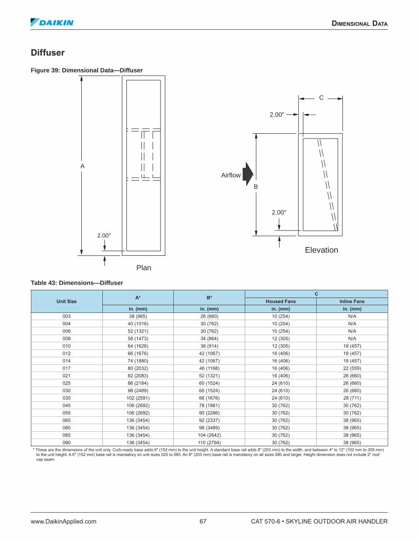
Diffuser
Figure 39: Dimensional Data—Diffuser
Table 43: Dimensions—Diffuser
Unit SizeA* B*
C
Housed Fans Inline Fans
in. (mm) in. (mm) in. (mm) in. (mm)003 38 (965) 26 (660) 10 (254) N/A004 40 (1016) 30 (762) 10 (254) N/A006 52 (1321) 30 (762) 10 (254) N/A008 58 (1473) 34 (864) 12 (305) N/A010 64 (1626) 36 (914) 12 (305) 18 (457)012 66 (1676) 42 (1067) 16 (406) 18 (457)014 74 (1880) 42 (1067) 16 (406) 18 (457)017 80 (2032) 46 (1168) 16 (406) 22 (559)021 82 (2083) 52 (1321) 16 (406) 26 (660)025 86 (2184) 60 (1524) 24 (610) 26 (660)030 98 (2489) 60 (1524) 24 (610) 26 (660)035 102 (2591) 66 (1676) 24 (610) 28 (711)045 106 (2692) 78 (1981) 30 (762) 30 (762)055 106 (2692) 90 (2286) 30 (762) 30 (762)065 136 (3454) 92 (2337) 30 (762) 38 (965)080 136 (3454) 98 (3489) 30 (762) 38 (965)085 136 (3454) 104 (2642) 30 (762) 38 (965)090 136 (3454) 110 (2794) 30 (762) 38 (965)
* These are the dimensions of the unit only. Curb-ready base adds 6" (152 mm) to the unit height. A standard base rail adds 8" (203 mm) to the width, and between 4" to 12" (102 mm to 305 mm) to the unit height. A 6" (152 mm) base rail is mandatory on unit sizes 025 to 065. An 8" (203 mm) base rail is mandatory on all sizes 080 and larger. Height dimension does not include 2" roof cap seam.
Plan
2.00"
A
Airflow
B
Elevation
2.00"
2.00"
C
dimensional daTa
www.DaikinApplied.com 67 CAT 570-6 • SKYLINE OUTDOOR AIR HANDLER

Economizer Section
Figure 40: Dimensional Data—Economizer Section
Table 44: Dimensions—Economizer
Unit SizeA* B*
C
D GDamper Width
Damper LengthEcon. Only
w/ 2" Flat
Filter
w/ 4" Flat
Filter
w/ 2" Angle Filter
w/ 4" Angle Filter
in. (mm) in. (mm) in. (mm) in. (mm) in. (mm) in. (mm) in. (mm) in. (mm) in. (mm) in. (mm) in. (mm)003 38 (965) 26 (660) 40 (1016) 44 (1118) 46 (1168) 62 (1575) N/A 16 (406) 34 (864) 12 (305) 24 (610)004 40 (1016) 30 (762) 40 (1016) 44 (1118) 46 (1168) 62 (1575) N/A 16 (406) 36 (914) 12 (305) 26 (660)006 52 (1321) 30 (762) 40 (1016) 44 (1118) 46 (1168) 62 (1575) N/A 16 (406) 48 (1219) 12 (305) 38 (965)008 58 (1473) 34 (864) 40 (1016) 44 (1118) 46 (1168) 62 (1575) 66 (1676) 16 (406) 54 (1372) 12 (305) 44 (1118)010 64 (1626) 36 (914) 44 (1118) 48 (1219) 50 (1270) 66 (1676) 70 (1778) 18 (457) 60 (1524) 14 (356) 50 (1270)012 66 (1676) 42 (1067) 48 (1219) 52 (1321) 54 (1372) 70 (1778) 74 (1880) 20 (508) 62 (1575) 16 (406) 52 (1321)014 74 (1880) 42 (1067) 48 (1219) 52 (1321) 54 (1372) 70 (1778) 74 (1880) 20 (508) 70 (1778) 16 (406) 60 (1524)017 80 (2032) 46 (1168) 52 (1321) 56 (1422) 58 (1473) 74 (1880) 78 (1981) 22 (559) 76 (1930) 18 (457) 66 (1676)021 82 (2083) 52 (1321) 60 (1524) 64 (1626) 66 (1676) 82 (2083) 86 (2184) 26 (660) 78 (1981) 22 (559) 68 (1727)025 86 (2184) 60 (1524) 64 (1626) 68 (1727) 70 (1778) 86 (2184) 90 (2286) 28 (711) 82 (2083) 24 (610) 72 (1829)030 98 (2489) 60 (1524) 64 (1626) 68 (1727) 70 (1778) 86 (2184) 90 (2286) 28 (711) 94 (2388) 24 (610) 84 (2134)035 102 (2591) 66 (1676) 72 (1829) 76 (1930) 78 (1981) 94 (2388) 98 (2489) 32 (813) 98 (2489) 28 (711) 88 (2235)045 106 (2692) 78 (1981) 88 (2235) 92 (2337) 94 (2388) 110 (2794) 114 (2896) 40 (1016) 102 (2591) 36 (914) 92 (2337)055 106 (2692) 90 (2286) 104 (2643) 108 (2743) 110 (2794) 126 (3200) 130 (3302) 48 (1219) 102 (2591) 44 (1118) 92 (2337)065 136 (3454) 92 (2337) 92 (2337) 96 (2438) 98 (2489) 114 (2896) 118 (2997) 42 (1067) 132 (3353) 38 (965) 122 (3099)080 136 (3454) 98 (3489) 100 (2540) 108 (2743) 112 (2845) 144 (3658) 152 (3861) 46 (1168) 132 (3353) 42 (1067) 122 (3099)085 136 (3454) 104 (2642) 108 (2743) 116 (2946) 120 (3048) 152 (3861) 160 (4064) 50 (1270) 132 (3353) 46 (1168) 122 (3099)090 136 (3454) 110 (2794) 112 (2845) 120 (3048) 124 (3150) 156 (3962) 164 (4166) 52 (1321) 132 (3353) 48 (1219) 122 (3099)
* These are the dimensions of the unit only. Curb-ready base adds 6" (152 mm) to the unit height. A standard base rail adds 8" (203 mm) to the width, and between 4" to 12" (102 mm to 305 mm) to the unit height. A base rail—mandatory on unit sizes 025 to 065—adds a minimum of 6" (152 mm) to the unit height. Unit sizes greater than 080 require a base rail that adds a minimum of 8" (203 mm) to the unit height.
Elevation
Plan
2.00"
2.00"
AAirflow
B
G
2.00" 2.00"
C
D D4"
Note: Dampers can be located in the top, bottom, drive side and opposite drive side, and end of the section. Top and bottom fresh air dampers are notavailable if hoods are selected.
CAT 570-6 • SKYLINE OUTDOOR AIR HANDLER 68 www.DaikinApplied.com
dimensional daTa
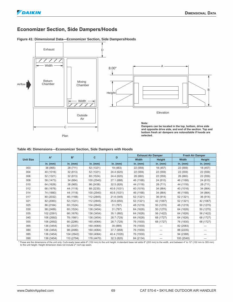
Economizer Section, Side Dampers/Hoods
Figure 41: Dimensional Data—Economizer Section, Side Dampers/Hoods
Table 45: Dimensions—Economizer Section, Side Dampers with Hoods
Unit SizeA* B* C D
Exhaust Air Damper Fresh Air Damper
Width Height Width Height
in. (mm) in. (mm) in. (mm) in. (mm) in. (mm) in. (mm) in. (mm) in. (mm)003 38 (965) 28 (711) 52 (1321) 19 (483) 22 (559) 18 (457) 22 (559) 18 (457)004 40 (1016) 32 (813) 52 (1321) 24.4 (620) 22 (559) 22 (559) 22 (559) 22 (559)006 52 (1321) 32 (813) 60 (1524) 24.4 (620) 26 (660) 22 (559) 26 (660) 22 (559)008 58 (1473) 34 (864) 100 (2540) 27.1 (688) 46 (1168) 24 (610) 46 (1168) 24 (610)010 64 (1626) 38 (965) 96 (2438) 32.5 (826) 44 (1118) 28 (711) 44 (1118) 28 (711)012 66 (1676) 44 (1118) 88 (2235) 40.6 (1031) 40 (1016) 34 (864) 40 (1016) 34 (864)014 74 (1880) 44 (1118) 100 (2540) 40.6 (1031) 46 (1168) 34 (864) 46 (1168) 34 (864)017 80 (2032) 46 (1168) 112 (2845) 21.6 (549) 52 (1321) 36 (914) 52 (1321) 36 (914)021 82 (2083) 52 (1321) 112 (2845) 25.6 (650) 52 (1321) 42 (1067) 52 (1321) 42 (1067)025 86 (2184) 60 (1524) 104 (2642) 31 (787) 48 (1219) 50 (1270) 48 (1219) 50 (1270)030 98 (2489) 60 (1524) 136 (3454) 31 (787) 64 (1626) 50 (1270) 64 (1626) 50 (1270)035 102 (2591) 66 (1676) 136 (3454) 35.1 (892) 64 (1626) 56 (1422) 64 (1626) 56 (1422)045 106 (2692) 78 (1981) 136 (3454) 28.7 (729) 64 (1626) 68 (1727) 64 (1626) 68 (1727)055 106 (2692) 90 (2286) 160 (4064) 28.7 (729) 76 (1930) 68 (1727) 76 (1930) 68 (1727)065 136 (3454) 92 (2337) 160 (4064) 35 (889) 76 (1930) — 82 (2083) —080 136 (3454) 98 (2489) 160 (4064) 37.7 (958) 76 (1930) — 88 (2235) —085 136 (3454) 104 (2642) 160 (4064) 40.4 (1026) 76 (1930) — 94 (2388) —090 136 (3454) 110 (2794) 176 (4470) 32.3 (820) 84 (2134) — 100 (2540) —
* These are the dimensions of the unit only. Curb-ready base adds 6" (152 mm) to the unit height. A standard base rail adds 8" (203 mm) to the width, and between 4" to 12" (102 mm to 305 mm) to the unit height. Height dimension does not include 2" roof cap seam.
B
D
A
Width
Height
8.00"Width
C
AirflowMixingReturn
Plan
Elevation
Exhaust
OutsideAir
Chamber Chamber
Note: Dampers can be located in the top, bottom, drive side and opposite drive side, and end of the section. Top and bottom fresh air dampers are notavailable if hoods are selected.
dimensional daTa
www.DaikinApplied.com 69 CAT 570-6 • SKYLINE OUTDOOR AIR HANDLER
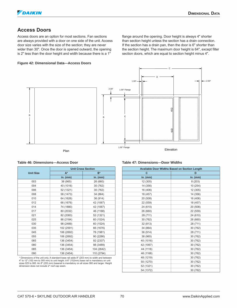
Access Doors
Access doors are an option for most sections. Fan sections are always provided with a door on one side of the unit. Access door size varies with the size of the section; they are never wider than 30". Once the door is opened outward, the opening is 2" less than the door height and width because there is a 1"
lange around the opening. Door height is always 4" shorter than section height unless the section has a drain connection. If the section has a drain pan, then the door is 6" shorter than the section height. The maximum door height is 64", except ilter section doors, which are equal to section height minus 4".
Figure 42: Dimensional Data—Access Doors
Table 46: Dimensions—Access Door
Unit Size
Unit Cross Section
A* B*
in. (mm) in. (mm)003 38 (965) 26 (660)004 40 (1016) 30 (762)006 52 (1321) 30 (762)008 58 (1473) 34 (864)010 64 (1626) 36 (914)012 66 (1676) 42 (1067)014 74 (1880) 42 (1067)017 80 (2032) 46 (1168)021 82 (2083) 52 (1321)025 86 (2184) 60 (1524)030 98 (2489) 60 (1524)035 102 (2591) 66 (1676)045 106 (2692) 78 (1981)055 106 (2692) 90 (2286)065 136 (3454) 92 (2337)080 136 (3454) 98 (3489)085 136 (3454) 104 (2642)090 136 (3454) 110 (2794)
* Dimensions of the unit only. A standard base rail adds 8" (203 mm) to width and between 4" to 12" (102 mm to 305 mm) to unit height. A 6" (152mm) base rail is mandatory on unit sizes 025 to 065. An 8" (203 mm) baserail is mandatory on all sizes 080 and larger. Height dimension does not include 2" roof cap seam.
Table 47: Dimensions—Door Widths
Available Door Widths Based on Section Length
C D
in. (mm) in. (mm)12 (305) 8 (203)14 (356) 10 (254)16 (406) 12 (305)18 (457) 14 (356)20 (508) 16 (406)22 (559) 18 (457)24 (610) 20 (508)26 (660) 22 (559)28 (711) 24 (610)30 (762) 26 (660)32 (813) 28 (711)34 (864) 30 (762)36 (914) 28 (711)38 (965) 30 (762)
40 (1016) 30 (762)42 (1067) 30 (762)44 (1118) 30 (762)46 (1168) 30 (762)48 (1219) 30 (762)50 (1270) 30 (762)52 (1321) 30 (762)54 (1372) 30 (762)
Elevation
2.00"
D
C
2.00" 1.00" Flange
1.00"
1.00" Flange
B E
Plan
B
CAT 570-6 • SKYLINE OUTDOOR AIR HANDLER 70 www.DaikinApplied.com
dimensional daTa
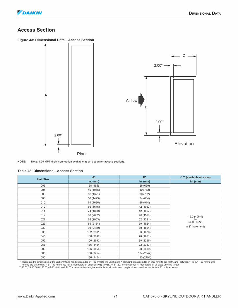
Access Section
Figure 43: Dimensional Data—Access Section
NOTE: Note: 1.25 MPT drain connection available as an option for access sections.
Table 48: Dimensions—Access Section
Unit SizeA* B* C ** (available all sizes)
in. (mm) in. (mm) in. (mm)003 38 (965) 26 (660)
16.0 (406.4) to
54.0 (1372)In 2ʺ increments
004 40 (1016) 30 (762)006 52 (1321) 30 (762)008 58 (1473) 34 (864)010 64 (1626) 36 (914)012 66 (1676) 42 (1067)014 74 (1880) 42 (1067)017 80 (2032) 46 (1168)021 82 (2083) 52 (1321)025 86 (2184) 60 (1524)030 98 (2489) 60 (1524)035 102 (2591) 66 (1676)045 106 (2692) 78 (1981)055 106 (2692) 90 (2286)065 136 (3454) 92 (2337)080 136 (3454) 98 (3489)085 136 (3454) 104 (2642)090 136 (3454) 110 (2794)
* These are the dimensions of the unit only.Curb-ready base adds 6" (152 mm) to the unit height. A standard base rail adds 8" (203 mm) to the width, and between 4" to 12" (102 mm to 305 mm) to the unit height. A 6" (152 mm) base rail is mandatory on unit sizes 025 to 065. An 8" (203 mm) base rail is mandatory on all sizes 080 and larger.
** 16.0", 24.0", 30.0", 36.0", 42.0", 48.0" and 54.0" access section lengths available for all unit sizes. Height dimension does not include 2" roof cap seam.
Plan
2.00"
A
Airflow
B
Elevation
2.00"
2.00"
C
dimensional daTa
www.DaikinApplied.com 71 CAT 570-6 • SKYLINE OUTDOOR AIR HANDLER
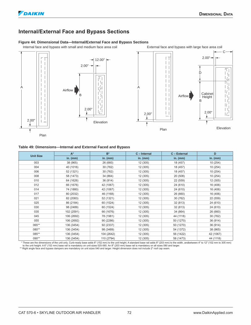
Internal/External Face and Bypass Sections
Figure 44: Dimensional Data—Internal/External Face and Bypass Sections
Table 49: Dimensions—Internal and External Faced and Bypass
Unit SizeA* B* C – Internal C – External D
in. (mm) in. (mm) in. (mm) in. (mm) in. (mm)003 38 (965) 26 (660) 12 (305) 18 (457) 10 (254)004 40 (1016) 30 (762) 12 (305) 18 (457) 10 (254)006 52 (1321) 30 (762) 12 (305) 18 (457) 10 (254)008 58 (1473) 34 (864) 12 (305) 20 (508) 10 (254)010 64 (1626) 36 (914) 12 (305) 22 (559) 12 (305)012 66 (1676) 42 (1067) 12 (305) 24 (610) 16 (406)014 74 (1880) 42 (1067) 12 (305) 24 (610) 16 (406)017 80 (2032) 46 (1168) 12 (305) 26 (660) 16 (406)021 82 (2083) 52 (1321) 12 (305) 30 (762) 22 (559)025 86 (2184) 60 (1524) 12 (305) 32 (813) 24 (610)030 98 (2489) 60 (1524) 12 (305) 32 (813) 24 (610)035 102 (2591) 66 (1676) 12 (305) 34 (864) 26 (660)045 106 (2692) 78 (1981) 12 (305) 44 (1118) 30 (762)055 106 (2692) 90 (2286) 12 (305) 50 (1270) 36 (914)
065** 136 (3454) 92 (2337) 12 (305) 50 (1270) 36 (914)080** 136 (3454) 98 (3489) 12 (305) 54 (1372) 38 (965)085** 136 (3454) 104 (2642) 12 (305) 56 (1422) 42 (1067)090** 136 (3454) 110 (2794) 12 (305) 58 (1473) 44 (1118)
* These are the dimensions of the unit only. Curb-ready base adds 6" (152 mm) to the unit height. A standard base rail adds 8" (203 mm) to the width, andbetween 4" to 12" (102 mm to 305 mm) to the unit height. A 6" (152 mm) base rail is mandatory on unit sizes 025-065. An 8" (203 mm) base rail is mandatory on all sizes 080 and larger.
** Right angle face and bypass dampers are mandatory on unit sizes 040 and larger. Height dimension does not include 2" roof cap seam.
Elevation
Plan
2.00"
A
2.00"
AirflowB
2.00"
12.00"
Plan
A
2.00"
Elevation
2.00"
AirflowB
2.00"
D
C
CabinetHeight
Internal face and bypass with small and medium face area coil External face and bypass with large face area coil
CAT 570-6 • SKYLINE OUTDOOR AIR HANDLER 72 www.DaikinApplied.com
dimensional daTa
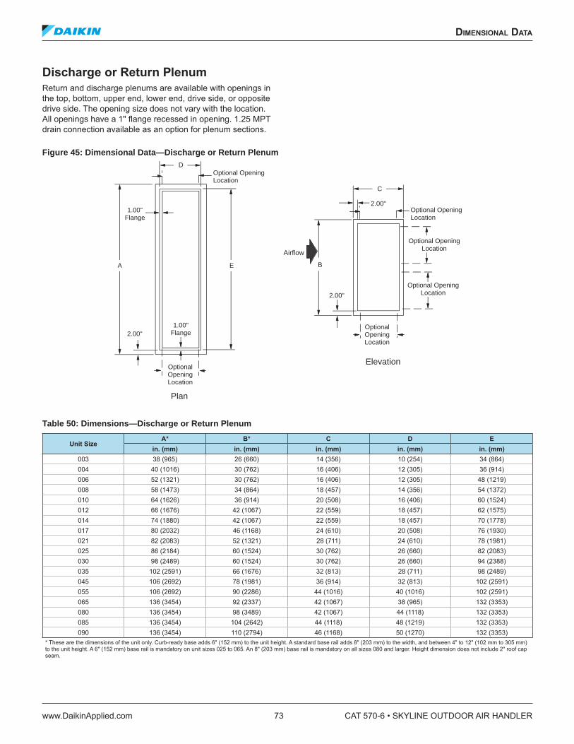
Discharge or Return Plenum
Return and discharge plenums are available with openings in the top, bottom, upper end, lower end, drive side, or opposite drive side. The opening size does not vary with the location. All openings have a 1" lange recessed in opening. 1.25 MPT drain connection available as an option for plenum sections.
Figure 45: Dimensional Data—Discharge or Return Plenum
Table 50: Dimensions—Discharge or Return Plenum
Unit SizeA* B* C D E
in. (mm) in. (mm) in. (mm) in. (mm) in. (mm)003 38 (965) 26 (660) 14 (356) 10 (254) 34 (864)004 40 (1016) 30 (762) 16 (406) 12 (305) 36 (914)006 52 (1321) 30 (762) 16 (406) 12 (305) 48 (1219)008 58 (1473) 34 (864) 18 (457) 14 (356) 54 (1372)010 64 (1626) 36 (914) 20 (508) 16 (406) 60 (1524)012 66 (1676) 42 (1067) 22 (559) 18 (457) 62 (1575)014 74 (1880) 42 (1067) 22 (559) 18 (457) 70 (1778)017 80 (2032) 46 (1168) 24 (610) 20 (508) 76 (1930)021 82 (2083) 52 (1321) 28 (711) 24 (610) 78 (1981)025 86 (2184) 60 (1524) 30 (762) 26 (660) 82 (2083)030 98 (2489) 60 (1524) 30 (762) 26 (660) 94 (2388)035 102 (2591) 66 (1676) 32 (813) 28 (711) 98 (2489)045 106 (2692) 78 (1981) 36 (914) 32 (813) 102 (2591)055 106 (2692) 90 (2286) 44 (1016) 40 (1016) 102 (2591)065 136 (3454) 92 (2337) 42 (1067) 38 (965) 132 (3353)080 136 (3454) 98 (3489) 42 (1067) 44 (1118) 132 (3353)085 136 (3454) 104 (2642) 44 (1118) 48 (1219) 132 (3353)090 136 (3454) 110 (2794) 46 (1168) 50 (1270) 132 (3353)
* These are the dimensions of the unit only. Curb-ready base adds 6" (152 mm) to the unit height. A standard base rail adds 8" (203 mm) to the width, and between 4" to 12" (102 mm to 305 mm) to the unit height. A 6" (152 mm) base rail is mandatory on unit sizes 025 to 065. An 8" (203 mm) base rail is mandatory on all sizes 080 and larger. Height dimension does not include 2" roof cap seam.
Elevation
Plan
A
Airflow
B
2.00"
D
E
2.00"
2.00"1.00"
Flange
1.00"Flange
C
Optional OpeningLocation
Optional OpeningLocation
Optional OpeningLocation
Optional OpeningLocation
Optional OpeningLocation
Optional OpeningLocation
dimensional daTa
www.DaikinApplied.com 73 CAT 570-6 • SKYLINE OUTDOOR AIR HANDLER
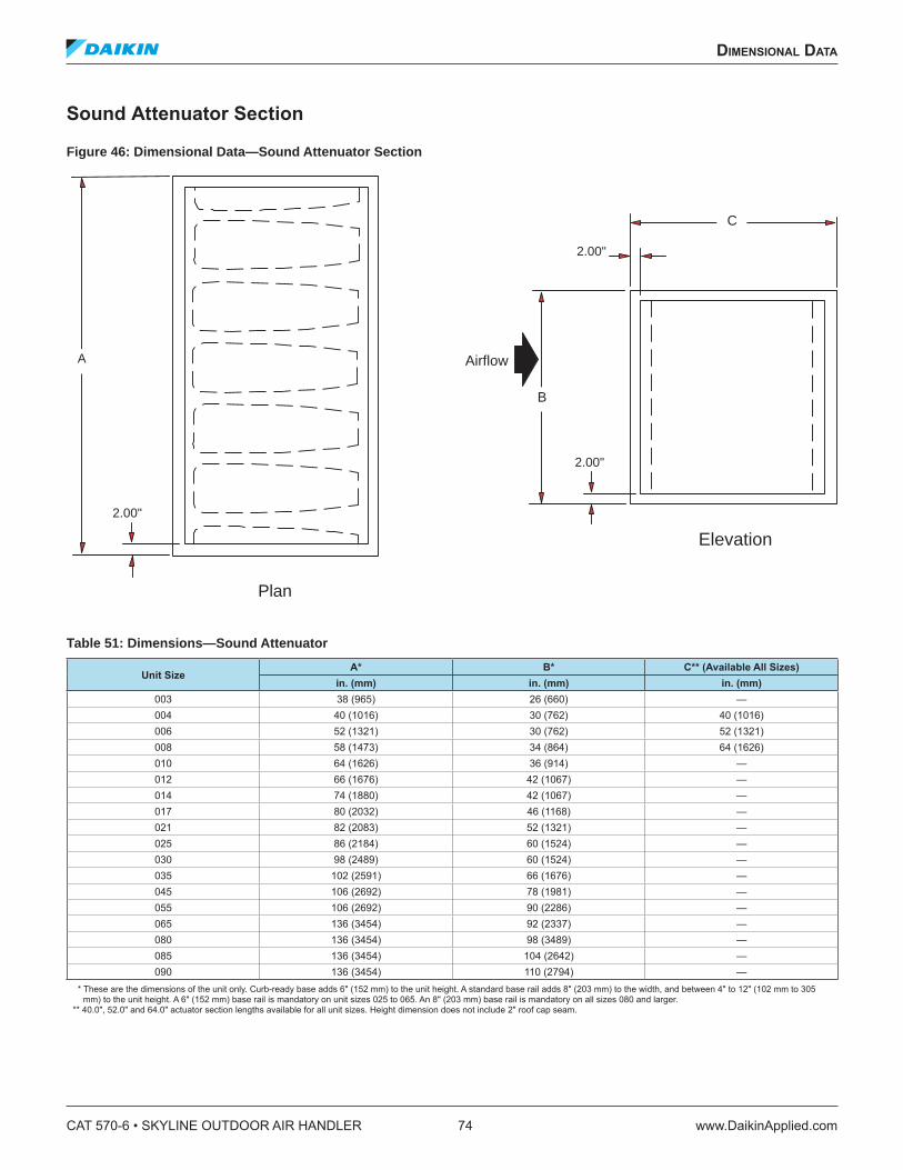
Sound Attenuator Section
Figure 46: Dimensional Data—Sound Attenuator Section
Table 51: Dimensions—Sound Attenuator
Unit SizeA* B* C** (Available All Sizes)
in. (mm) in. (mm) in. (mm)003 38 (965) 26 (660) —004 40 (1016) 30 (762) 40 (1016)006 52 (1321) 30 (762) 52 (1321)008 58 (1473) 34 (864) 64 (1626)010 64 (1626) 36 (914) —012 66 (1676) 42 (1067) —014 74 (1880) 42 (1067) —017 80 (2032) 46 (1168) —021 82 (2083) 52 (1321) —025 86 (2184) 60 (1524) —030 98 (2489) 60 (1524) —035 102 (2591) 66 (1676) —045 106 (2692) 78 (1981) —055 106 (2692) 90 (2286) —065 136 (3454) 92 (2337) —080 136 (3454) 98 (3489) —085 136 (3454) 104 (2642) —090 136 (3454) 110 (2794) —
* These are the dimensions of the unit only. Curb-ready base adds 6" (152 mm) to the unit height. A standard base rail adds 8" (203 mm) to the width, and between 4" to 12" (102 mm to 305 mm) to the unit height. A 6" (152 mm) base rail is mandatory on unit sizes 025 to 065. An 8" (203 mm) base rail is mandatory on all sizes 080 and larger.
** 40.0", 52.0" and 64.0" actuator section lengths available for all unit sizes. Height dimension does not include 2" roof cap seam.
Elevation
Plan
A Airflow
C
2.00"
B
2.00"
2.00"
CAT 570-6 • SKYLINE OUTDOOR AIR HANDLER 74 www.DaikinApplied.com
dimensional daTa
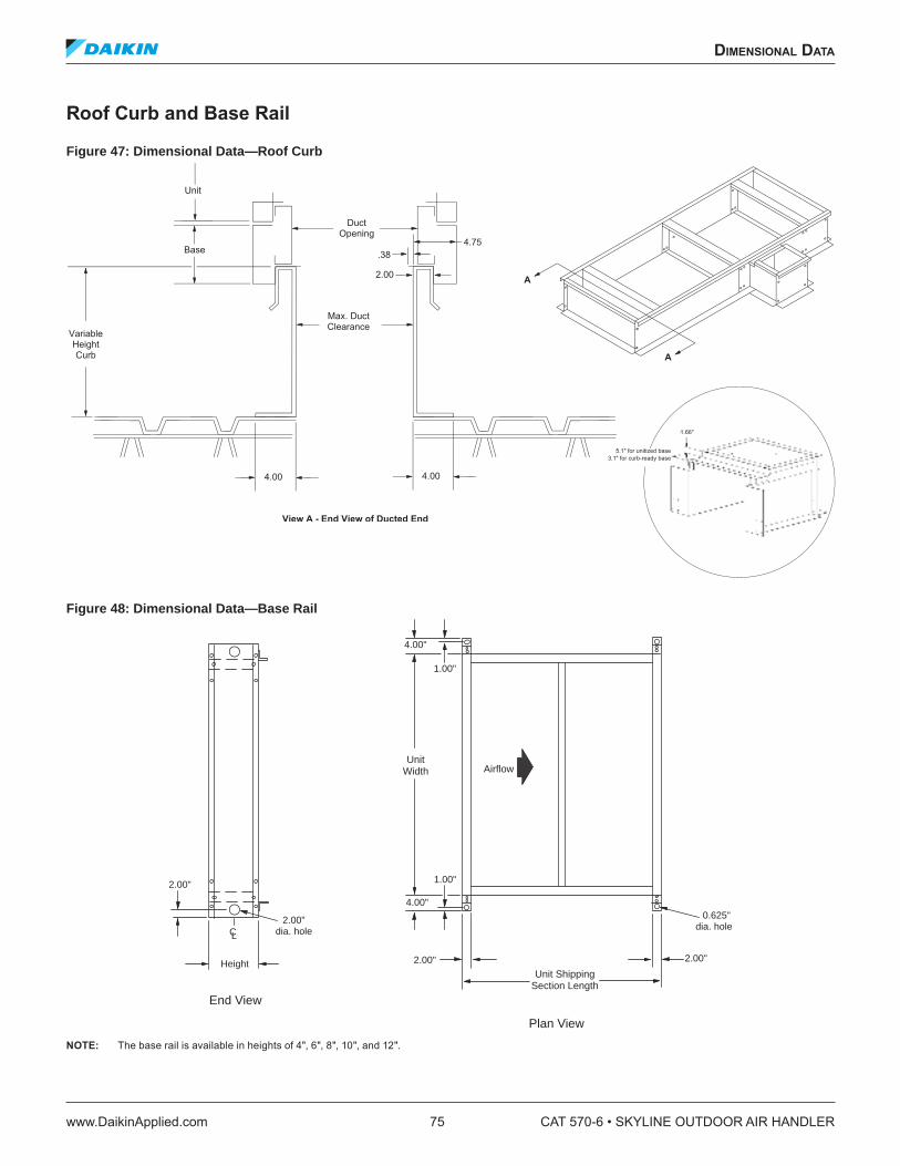
Roof Curb and Base Rail
Figure 47: Dimensional Data—Roof Curb
Figure 48: Dimensional Data—Base Rail
NOTE: The base rail is available in heights of 4", 6", 8", 10", and 12".
5.1ʺ for unitized base
3.1ʺ for curb-ready base
1.66ʺ
Airflow
2.00"
CL
Height
2.00"dia. hole
0.625"dia. hole
2.00" 2.00"
4.00"
1.00"
4.00"
1.00"
UnitWidth
Unit ShippingSection Length
End View
Plan View
dimensional daTa
www.DaikinApplied.com 75 CAT 570-6 • SKYLINE OUTDOOR AIR HANDLER
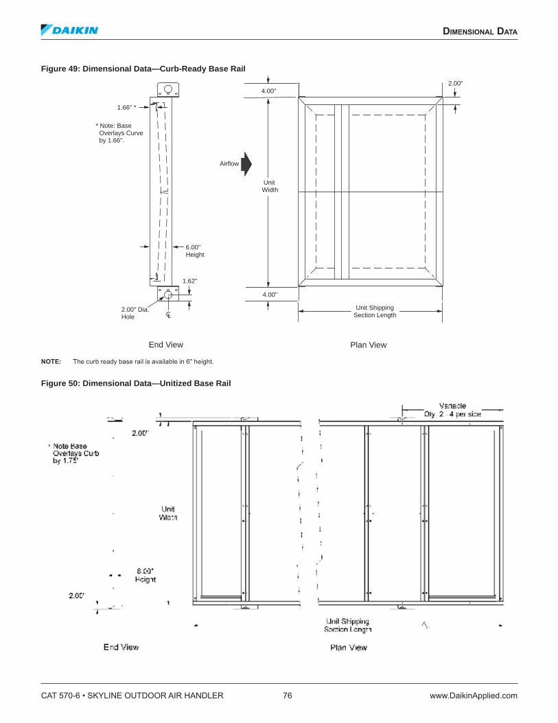
Figure 49: Dimensional Data—Curb-Ready Base Rail
NOTE: The curb ready base rail is available in 6" height.
Figure 50: Dimensional Data—Unitized Base Rail
1.66" *
4.00"
Airflow
Unit ShippingSection Length
Unit Width
4.00"
6.00"Height
CL2.00" Dia.Hole
1.62"
2.00"
* Note: Base Overlays Curve by 1.66".
End View Plan View
CAT 570-6 • SKYLINE OUTDOOR AIR HANDLER 76 www.DaikinApplied.com
dimensional daTa
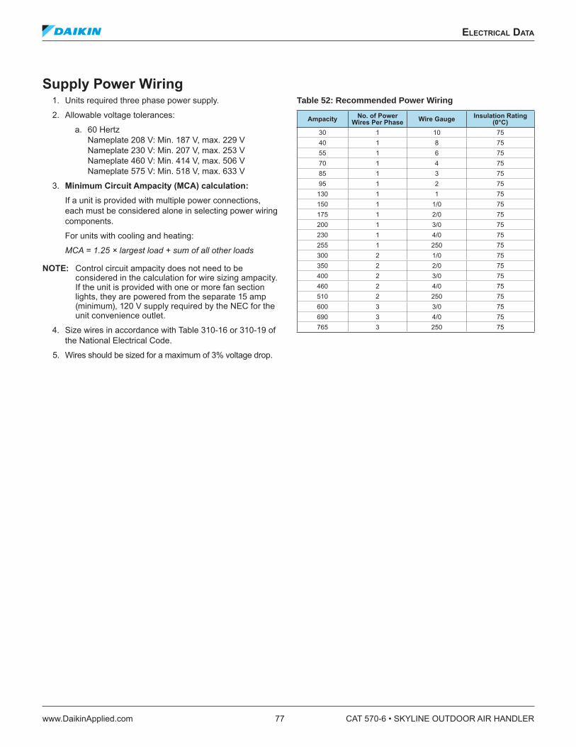
eleCTriCal daTa
Supply Power Wiring 1. Units required three phase power supply.
2. Allowable voltage tolerances:
a. 60 Hertz Nameplate 208 V: Min. 187 V, max. 229 V Nameplate 230 V: Min. 207 V, max. 253 V Nameplate 460 V: Min. 414 V, max. 506 V Nameplate 575 V: Min. 518 V, max. 633 V
3. Minimum Circuit Ampacity (MCA) calculation: If a unit is provided with multiple power connections, each must be considered alone in selecting power wiring components.
For units with cooling and heating:
MCA = 1.25 × largest load + sum of all other loads
NOTE: Control circuit ampacity does not need to be considered in the calculation for wire sizing ampacity. If the unit is provided with one or more fan section lights, they are powered from the separate 15 amp (minimum), 120 V supply required by the NEC for the unit convenience outlet.
4. Size wires in accordance with Table 310-16 or 310-19 of the National Electrical Code.
5. Wires should be sized for a maximum of 3% voltage drop.
Table 52: Recommended Power Wiring
AmpacityNo. of Power
Wires Per PhaseWire Gauge
Insulation Rating (0°C)
30 1 10 75
40 1 8 75
55 1 6 75
70 1 4 75
85 1 3 75
95 1 2 75
130 1 1 75
150 1 1/0 75
175 1 2/0 75
200 1 3/0 75
230 1 4/0 75
255 1 250 75
300 2 1/0 75
350 2 2/0 75
400 2 3/0 75
460 2 4/0 75
510 2 250 75
600 3 3/0 75
690 3 4/0 75
765 3 250 75
eleCTriCal daTa
www.DaikinApplied.com 77 CAT 570-6 • SKYLINE OUTDOOR AIR HANDLER
engineering guide speCifiCaTion
PART 1: GENERAL
1.01 SECTION INCLUDES
A. Outdoor air handling units.
1.02 REFERENCES
A. AFBMA 9 - Load Ratings and Fatigue Life for Ball Bearings
B. AMCA 99 - Standards Handbook C. AMCA 210 - Laboratory Methods of Testing Fans for
Rating Purposes D. AMCA 300 - Test Code for Sound Rating Air Moving
Devices E. AMCA 500 - Test Methods for Louver, Dampers, and
Shutters F. AHRI 410 - Forced-Circulation Air-Cooling and Air-
Heating Coils G. AHRI 430 - Central-Station Air-Handling Units. H. AHRI 435 - Application of Central-Station Air-
Handling Units I. ASTMB117 – Standard Practice for Operating Salt
Spray Apparatus J. NEMA MG1 - Motors and Generators. K. NFPA 70 - National Electrical Code. L. SMACNA - HVAC Duct Construction Standards -
Metal and Flexible. M. UL 723 – Test for Surface Burning Characteristics of
Building Materials N. UL 900 - Test Performance of Air Filter Units. O. UL 1995 – Standard for Heating and Cooling
Equipment P. UL 94 – Test for Flammability of Plastic Materials for
Parts in Devices and Appliances Q. IBC 2000, 2003 – International Building Code R. NFPA 90A – Standard for the Installation of Air
Conditioning and Ventilating Systems S. NFPA 5000 – Building Construction and Safety Code T. ASHRAE 90.1 Energy Code U. AHRI Standard 1060 – Rating Air-to-Air Heat
Exchangers for Energy Recovery Ventilation Equipment
V. GSA 2003 Facilities Standard - 5.9 HVAC Systems and Components
1.03 SUBMITTALS
A. Shop Drawings: Indicate assembly, unit dimensions, weight loading, required clearances, construction details, ield connection details, and electrical characteristics and connection requirements. Computer generated fan curves for each air handling unit shall be submitted with speciic design operating point noted. A computer generated psychometric chart shall be submitted for each cooling coil with design points and inal operating point clearly noted. Sound data for discharge, radiated and return positions shall be submitted by octave band for each unit. Calculations for required baserail heights to satisfy condensate trapping requirements of cooling coil shall be included.
B. Product Data: 1. Provide literature that indicates dimensions,
weights, capacities, ratings, fan performance, and electrical characteristics and connection requirements.
2. Provide data of ilter media, ilter performance data, ilter assembly, and ilter frames.
C. Manufacturer’s Installation Instructions.
1.04 QUALIFICATIONS
A. Manufacturers specializing in manufacturing Air Handling Units speciied in this section must prove minimum ive years documented experience and issue a complete catalog on total product.
1.05 SAFETY AGENCY LISTED & CERTIFICATION
A. Air handling units shall be cETLus safety listed that conforms to UL Standard 1995 and CAN/CSA Standard C22.2 No. 236. Units shall be accepted for use in New York City by the Department of Building, MEA 342-99-E.
B. Air handler furnished with double width, double inlet (DWDI) and/or plenum fans shall be certiied in accordance with the central station air handling units certiication program, which is based on AHRI 430. (NOTE: Above does not apply to fan array)
C. Air handling unit water heating & cooling coils shall be certiied in accordance with the forced circulation air cooling and air heating coils certiication program, which is based on AHRI Standard 410.
CAT 570-6 • SKYLINE OUTDOOR AIR HANDLER 78 www.DaikinApplied.com
engineering guide speCifiCaTion
1.06 DELIVERY, STORAGE, AND HANDLING
A. Deliver, store, protect and handle products to site. B. Accept products on site in factory-fabricated
protective containers, with factory-installed shipping skids. Inspect for damage.
C. Store in clean dry place and protect from weather and construction trafic. Handle carefully to avoid damage to components, enclosures, and inish.
PART 2: PRODUCTS
2.01 MANUFACTURERS
A. The following manufacturers are approved for use. No substitutions will be permitted. 1. Daikin Applied as basis of design 2. Miller-Picking 3. Temtrol 4. Scott-Springield 5. Racan-Carrier Company
2.02 GENERAL DESCRIPTION
A. Coniguration: Fabricate as detailed on drawings. B. Performance: Conform to AHRI 430. See schedules on
prints. (NOTE: Above does not apply to fan array)C. Acoustics: Sound power levels (dB) for the unit
shall not exceed the following speciied levels. The manufacturer shall provide the necessary sound treatment to meet these levels if required.
Octave Band at Center Frequency (Hz)63 125 250 500 1000 2000 4000 8000
RadiatedDischarge
Return
D. [IBC Certiication 1. All components included herein are designed,
manufactured and independently tested, rated and certiied to meet the seismic compliance standards of the International Building Code. Components designated for use in systems that are life safety, toxic, high hazard, combustible or lammable shall meet the on line, anchorage and load path requirements for life safety as deined in IBC sections 1621.1.6, 1621.3.3, 1707.7.2, and IBC Commentary, Volume II, section 1621.1.6, IBC notes pertaining to the release of hazardous material. All components used as part of a system other than the above shall meet as a minimum, all load path and anchorage standards for components as outlined in IBC section 1621.3.3 & 1707.7.2.
2. Certiication is good for [Fp/Wp = 2.89 gs and Sds = 1.29 gs obtained from a “maximum considered earth quake short period spectral response acceleration Ss of 1.93.] [Fp/Wp = 4.42 gs and Sds = 1.96 gs obtained from a “maximum considered earth quake short period spectral response acceleration Ss of 2.94.]
3. All completed component assemblies shall be clearly labelled for ield inspection. Seismic Compliance Labels shall include the manufacturer’s identiication, designation of certiied models, deinitive information describing the product’s compliance characteristics, and the Independent Certifying Agency’s name and report identiication.
4. In addition to all seismic requirements for IBC Certiication listed elsewhere in the project speciication, manufacturer’s submittals shall include : a. Certiicate of Compliance from the
Independent Certifying Agency clearly indicating that components supplied on this project are included in the component manufacturer’s Certiicate of Compliance.
b. Clear installation instructions including all accessory components that are part of the overall component installation.]
engineering guide speCifiCaTion
www.DaikinApplied.com 79 CAT 570-6 • SKYLINE OUTDOOR AIR HANDLER

2.03 UNIT CONSTRUCTION
A. Fabricate unit with 16 gauge channel posts and panels secured with mechanical fasteners. All panels, access doors, and ship sections shall be sealed with permanently applied bulb-type gasket. Shipped loose gasketing is not allowed. 1. Panels and access doors shall be constructed
as a 2-inch (50-mm) nominal thick; thermal broke double wall assembly, injected with foam insulation for an R-value of not less than R-13. The outer panel shall be constructed of G60 painted galvanized [18-gauge] steel. The inner liner shall be constructed of G90 galvanized [solid stainless] steel.
2. Panel delection shall not exceed L/240 ratio at 125% of design static pressure, maximum positive or negative 8 inches of static pressure. Delection shall be measured at the midpoint of the panel height.
3. The casing leakage rate shall not exceed [.5 cfm per square foot of cabinet area at 6 inches of negative static pressure or 5 inches of positive static pressure (0.0025 m2/s per square meter of cabinet area at 1.24 kPa static pressure)] [1% of supply air volume at design static pressure up to positive or negative 8 inches (1.99 kPa)] or [ASHRAE 111 CL 6 at design pressure up to positive or negative 8 inches (1.99 kPa), where casing leakage (cfm/100 ft2 of casing surface are) = CL × P0.65].
4. Module to module assembly shall be accomplished with an overlapping, full perimeter, insulated, internal splice joint sealed with bulb type gasketing on both mating modules to minimize on-site labor and meet indoor air quality standards.
5. Factory leakage test available for custom air handling units. The unit manufacturer shall provide a witnessed factory leak test on selected units. The cabinet shall be tested at the unit’s positive and negative maximum design operating static pressure, up to 8" of differential static pressure across the cabinet exterior walls for the entire unit. Cabinet leakage shall not exceed Class 6 leakage per ASHRAE Standard 111. All supply and return opening shall be sealed. Air pressure and low shall be measured by a third party calibrated and certiied apparatus. The testing shall be performed at the factory. Owner’s representative shall select on unit to be tested at the time of order. A written test report shall be prepared by the manufacturer and issued to the owner’s representative.
6. Factory panel delection testing available for Custom Air Handler units. The unit manufacturer shall provide a factory delection test on one unit at the unit’s positive and negative maximum design operating static pressure, up to 8" of differential static pressure across the cabinet exterior walls for the entire unit. A delection limit of L/240 will be demonstrated at this time. “L” is deined as the height of a panel on the side of the unit. Measurement shall be at the mid-point of “L” along the largest panel on one side. Owner’s representative shall select on unit to be tested at the time of order. A written test report shall be prepared by the manufacturer and issued to the owner’s representative.
7. [A sound bafle shall be secured to the inner liner and constructed of G90 galvanized perforated steel illed with glass iber insulation.]
8. [An optional 0.044" thick aluminium treadplate shall be secured to the loor panel.]
9. [Entire unit shall have a [4] [6] [8] [10] [12]-inch full perimeter base rail for structural rigidity and condensate trapping. The following calculation shall determine the required height of the baserail to allow for adequate drainage. Use the largest pressure to determine base rail height. [(Negative)(Positive) static pressure (in)] (2) + 4" = required baserail height. Should the unit baserail not be factory supplied at this height, the contractor is required to supply a concrete housekeeping pad to make up the difference.] [The unit shall be equipped with a unitized base and shall overhang the roof curb for positive water runoff and shall seat on the roof curb gasket to provide a positive, weather tight seal. Lifting brackets shall be provided on the unit base to accept cable or chain hooks for rigging the equipment.]
10. [Roof Curb kit of [16"] [20"] [24"] [30"] height shall provide support for the air handler on the building roof and provide a weather protected area for terminating and securing the roof membrane. The roof curb kit shall be manufactured and shipped separately from the air handler.]
11. [Coil piping vestibule [18"] [24"] [30"] shall be factory installed of standard cabinet construction on the coil connection side of the unit. Roofcap over vestibule shall be a continuous single piece covering both the coil section and the vestibule. Roofcap seams between coil section and vestibule are not allowed.]
CAT 570-6 • SKYLINE OUTDOOR AIR HANDLER 80 www.DaikinApplied.com
engineering guide speCifiCaTion
B. Access Doors shall be lush mounted to cabinetry, with minimum of two six inch long stainless steel piano-type hinges, latch and full size (4.5" minimum) handle assembly (provide inspection window for fan section). Door shall swing outward for unit sections under negative pressure (inward for unit sections under positive pressure). Doors limited from swinging inward (such as side access ilter sections) on positive pressure sections, shall have a secondary latch to relieve pressure and prevent injury upon access.
C. Construct drain pans from [microbial resistant coated galvanized steel] [stainless steel] with cross break and double sloping pitch to drain connection. Provide drain pans under cooling coil section [fan section]. Drain connection centerline shall be a minimum of 3" above the base rail to aid in proper condensate trapping. Drain connections that protrude from the base rail are not acceptable. There must be a full 2" thickness of insulation under drain pan.
2.04 SUPPLY / RETURN FANS
A. Provide [DWDI forward-curved] [DWDI airfoil] [beltdrive airfoil plenum] [direct-drive airfoil plenum] [inline][fan array] [DWDI forward curved twin] supply [return] fan(s). Fan assemblies including fan, motor and sheaves shall be dynamically balanced by the manufacturer on all three planes and at all bearing supports. Manufacturer must ensure maximum fan RPM is below the irst critical speed. Fan array
1. Fan array shall have number of fans as scheduled.
2. Fan array section shall come with sound absorbing panels installed around each fan.
3. Fan array shall have fans individually isolated with [Rubber in Shear(RIS)][spring] isolation.
4. Walk in section placed downstream for motor access. [Section shall come installed with tread plate installed in the loor. [Section shall come with motor removal hoist installed]
5. [Unit shall be equipped with a manual block-off plate for mounting in the fan inlet][Unit shall come equipped with an isolation damper upstream of each fan in the array. Damper shall be equipped with an adjustable, weighted counter balance to minimize static pressure loss][Unit shall come equipped with an actuated damper upstream of each fan. An external signal shall close the damper in the event of a fan failure.]
6. [Fan array section shall come with an externally mounted junction box to allow for ield wiring of the fan array motors]
7. [Fan section shall come equipped with motor control panel with short circuit protection complete with variable frequency drives.]a. [Fan array shall be equipped with one variable
frequency drive wired to all fans][Fan array shall have a redundant drive wired to all fans]
b. b. [Fan array shall be equipped with one variable frequency drive wired to all fans in a given row in the fan array.]
c. c.[Fan array shall be equipped with on variable frequency drive wired to each of the fans in the fan array]
8. [Motor control panel shall come equiped with a [fused][non-fused] disconnect switch]
9. [Fan array shall be equiped with Piezometer rings to measure airlow][One piexometer ring shall be supplied on [eachfan][each row][one fan] in the fan array]
Multiple direct drive fans
1. Unit shall have [two] [three] [9] [12] blade direct drive class II fans with [2" spring isolation] [rubber-in-shear isolation (fan sizes 36 and smaller)] [2" seismic isolation].
2. [Manual block-off] [Isolation damper [with actuator]] mounted upstream of fan for isolation of individual fans.
3. [Single source power motor control panel with short circuit protection and [Non-fused disconnect] [fused disconnect] [Circuit breaker] factory wired from panel to motors in conduit. Variable speed control by [Daikin Applied brand VFD(s)] [ABB] [Danfoss].] [Fan on-off and speed control by others shall be provided.]
B. Bearings shall be self-aligning, grease lubricated, ball or roller bearings with extended copper lubrication lines to access side of unit. Grease ittings shall be attached to the fan base assembly near access door. If not supplied at the factory, contractor shall mount copper lube lines in the ield.
C. Fan and motor shall be mounted internally on a steel base. Factory mount motor on slide base that can be slid out the side of unit if removal is required. Provide access to motor, drive, and bearings through hinged access door. Fan and motor assembly shall be mounted on [rubber-in-shear vibration type isolators inside cabinetry.] [2" delection spring vibration type isolators inside cabinetry] [unit base, rigid mounted.] [Seismic snubbers shall be provided.]
engineering guide speCifiCaTion
www.DaikinApplied.com 81 CAT 570-6 • SKYLINE OUTDOOR AIR HANDLER
D. 2.05 BEARINGS AND DRIVES
(Not applicable to direct drive fans or fan array) A. Bearings: Basic load rating computed in accordance
with AFBMA - ANSI Standards, [L-50 life at 200,000 hours – all DWDI fans] [L-50 life at 500,000 hours – DWDI fans on unit sizes 003 - 035], [L-50 life at 400,000 hours all belt-drive airfoil plenum fans and DWDI fans on unit sizes greater than 035] [L-50 life 1,000,000 hours – DWDI fans on unit sizes 003 – 035] [L-50 life at 600,000 hours – all inline fans], heavy duty pillow block type, self-aligning, grease-lubricated ball bearings.
B. Shafts shall be solid, hot rolled steel, ground and polished, keyed to shaft, and protectively coated with lubricating oil. Hollow shafts are not acceptable.
C. V-Belt drives shall be cast iron or steel sheaves, dynamically balanced, bored to it shafts and keyed. [Fixed sheaves, matched belts, and drive rated based on motor horsepower] [Variable and adjustable pitch sheaves selected so required RPM is obtained with sheaves set at mid-position and rated based on motor horsepower. Contractor to furnish ixed sheaves at inal RPM as determined by balancing contractor]. Minimum of 2 belts shall be provided on all fans with 10 HP motors and above. Standard drive service factor shall be [1.1 S.F. (for 1/4 HP – 7.5 HP)] [1.3 S.F. (for 10HP and larger)], calculated based on fan brake horsepower.
2.06 ELECTRICAL
A. The air handler(s) shall be ETL and ETL-Canada listed by Intertek Testing Services, Inc. Units shall conform to bi-national standard ANSI/UL Standard 1995/CSA Standard C22.2 No. 236.
B. Wiring Termination: Provide terminal lugs to match branch circuit conductor quantities, sizes, and materials indicated. Enclosed terminal lugs in terminal box sized to NFPA 70.
C. [Provide [marine light] [marine light and GFI receptacle] in [fan] [each] section mounted and wired to a junction box and on-off switch mounted on the outside of the cabinet.
D. Fan motors shall be [1200] [1800] [3600] rpm, [open drip-proof (ODP)] [ totally enclosed fan-cooled (TEFC)] [1800/ 1200 rpm, 2 Speed/2 Winding (ODP) (TEFC)] [1800/900 rpm, 2 Speed/1 Winding (ODP)(TEFC)] type. Motors shall be [standard eficiency.] [high eficiency to meet EPAct requirements.] [premium eficiency.] Electrical characteristics shall be as shown in schedule.
E. [Air handler manufacturer shall provide and mount conduit and wiring from each fan motor terminated at [an external junction box.] [a non-fused] [a fused] [a circuit breaker] type disconnect switch factory wired. The disconnect switch shall be furnished with a rotary or switch-blade type handle that can be padlocked in the ‘off’ position.] [A motor starter [IEC] [NEMA] type shall be provided.]
F. [Air handler manufacturer shall provide and mount [Daikin Applied] [ABB] [Danfoss] variable speed drive with electrical characteristics as shown on project schedule. [A two-contactor type bypass switch shall be provided.] [A line reactor shall be provided.]
G. [Air handler manufacturer shall provide and mount a handoff-auto (HOA) switch.]
H. [Air handler manufacturer shall provide and mount a [24V] [120V] transformer.]
I. [Manufacturer must provide ASHRAE 90.1 Energy Eficiency equation details for individual equipment to assist Building Engineer for calculating system compliance.]
CAT 570-6 • SKYLINE OUTDOOR AIR HANDLER 82 www.DaikinApplied.com
engineering guide speCifiCaTion

2.07 COOLING AND HEATING COIL SECTIONS
A. Provide access to coils from [both sides] [connection side] [opposite side] of unit for service and cleaning. Enclose coil headers and return bends fully within unit casing. Unit shall be provided with coil connections that extend a minimum of 5" beyond unit casing for ease of installation. Drain and vent connections shall be provided exterior to unit casing. Coil connections must be factory sealed with grommets on interior and exterior and gasket sleeve between outer wall and liner where each pipe extends through the unit casing to minimize air leakage and condensation inside panel assembly. If not factory packaged, Contractor must supply all coil connection grommets and sleeves. Coils shall be removable through side and/or top panels of unit without the need to remove and disassemble the entire section from the unit. 1. Identify in, tube & casing material type and
thickness. 2. Show coil weights (shipping & operating). 3. State air and luid low amounts with its
associated pressure drops. For steam coils, indicate steam pressure and condensate load.
4. Indicate entering & leaving air and water temperatures. For refrigerant coils, indicate saturated suction temperature (SST).
B. Water Coils: 1. Certiication - Acceptable water coils are to be
certiied in accordance with AHRI Standard 410 and bear the AHRI label. Coils exceeding the scope of the manufacturer’s certiication and/or the range of AHRI’s standard rating conditions will be considered provided the manufacturer is a current member of the AHRI Air-Cooling and Air-Heating Coils certiication programs and that the coils have been rated in accordance with AHRI Standard 410. Manufacturer must be ISO 9002 certiied.
1. Headers shall consist of seamless copper tubing to assure compatibility with primary surface. Headers to have intruded tube holes to provide maximum brazing surface for tube to header joint, strength, and inherent lexibility. Header diameter should vary with luid low requirements.
2. Fins shall have a minimum thickness of [[0.0075"] [0.0095"] of aluminum] or [0.006"] [0.0075"] [0.0095"] copper]] plate construction. Fins shall have full drawn collars to provide a continuous surface cover over the entire tube for maximum heat transfer. Tubes shall be mechanically expanded into the ins to provide a continuous primary to secondary compression bond over the entire inned length for maximum heat transfer rates. Bare copper tubes shall not be visible between ins.
3. Coil tubes shall be 5/8 inch (16mm) OD seamless copper, 0.020" [0.025"] [0.035"] [0.049"] nominal tube wall thickness, expanded into ins, brazed at joints. Soldered U-bends shall be provided to minimize the effects of erosion and premature failure having a minimum tube wall thickness of 0.025".
4. Coil connections shall be [N.P.T. threaded carbon steel] [butt weld carbon steel] [O.D. sweat copper] [threaded red brass] with connection size to be determined by manufacturer based upon the most eficient coil circuiting. Vent and drain ittings shall be furnished on the connections, exterior to the air handler. Vent connections provided at the highest point to assure proper venting. Drain connections shall be provided at the lowest point to insure complete drainage and prevent freeze-up.
5. Coil casings shall be a formed channel frame of [galvanized steel] [stainless steel]. Water heating coils, 1 & 2 row only (sans 5M type) shall be furnished as uncased to allow for thermal movement and slide into a pitched track for luid drainage.
engineering guide speCifiCaTion
www.DaikinApplied.com 83 CAT 570-6 • SKYLINE OUTDOOR AIR HANDLER
C. Refrigerant Coils: 1. Certiication - Acceptable refrigerant coils are to
be certiied in accordance with AHRI Standard 410 and bear the AHRI label. Coils exceeding the scope of the manufacturer’s certiication and/or the range of AHRI’s standard rating conditions will be considered provided the manufacturer is a current member of the AHRI Air-Cooling and Air-Heating Coils certiication programs and that the coils have been rated in accordance with AHRI Standard 410. Manufacturer must be ISO 9002 certiied.
2. Coils designed for use with Refrigerant [R-22] [R134a] [other]. Fins shall have a minimum thickness of [[0.0075"] [0.0095"] of aluminum] or [0.006"] [0.0075"] [0.0095"] copper]] plate construction with full drawn collars to provide a continuous surface cover over the entire tube for maximum heat transfer. Tubes shall be mechanically expanded into the ins to provide a continuous primary-to-secondary compression bond over the entire inned length for maximum heat transfer rates. Bare copper tube shall not be visible between ins.
3. Refrigerant coils shall be provided with round seamless 5/8" O.D. copper tubes on 1-1/2" centers, staggered in the direction of airlow. All joints shall be brazed.
4. Sweat type copper suction connections located at the bottom of the suction headers for gravity oil drainage. Coils shall be uniformly circuited in a counterlow manner for [single circuit] [row] [face] [interlaced] [interlaced face split] capacity reduction. Pressure type liquid distributors used. Coils shall be tested with 315 pounds air pressure under warm water, and suitable for 250 psig working pressure.
D. Steam Coils: 1. Certiication - Acceptable steam coils are to be
certiied in accordance with AHRI Standard 410 and bear the AHRI label. Coils exceeding the scope of the manufacturer’s certiication and/or the range of AHRI’s standard rating conditions will be considered provided the manufacturer is a current member of the AHRI Air-Cooling and Air-Heating Coils certiication programs and that the coils have been rated in accordance with AHRI Standard 410. Manufacturer must be ISO 9002 certiied.
2. Fins shall have a minimum thickness of [[0.0075"] [0.0095"] [0.012" (1" dia. tubes only)] of aluminum] or [0.006" (5/8" tube dia. only)] [0.0075"] [0.0095"] copper]] with full drawn collars to provide a continuous surface cover over the entire tube for maximum heat transfer. Tubes shall be mechanically expanded into the ins to provide a continuous primary-to-secondary compression bond over the entire inned length for maximum heat transfer rates. Bare copper tubes shall not be visible between ins.
3. Steam coils shall be provided with round seamless [5/8" O.D. copper [0.020"] [0.025"] [0.035"] [0.049"] or [1" O.D. copper [0.025"] [0.049"] tubes. Tubes on two-row coils are staggered in the direction of airlow. All joints shall be brazed.
4. Steam coil headers shall be made of nonferrous materials using seamless copper tubing with intruded tube holes to permit expansion and contraction without creating undue stress or strain. Both the supply and return headers shall be completely encased by the coil casing. Coil shall be pitched in the unit to assure positive condensate drainage. Steam coils shall be furnished as uncased to allow for thermal movement and slide into a pitched track for drainage. Oriiced bafle plates shall be installed in the supply connection to ensure proper diffusion of entering steam.
5. Steam coils shall be tested with 315 pounds air pressure under warm water and suitable for 150 psig working pressures.
CAT 570-6 • SKYLINE OUTDOOR AIR HANDLER 84 www.DaikinApplied.com
engineering guide speCifiCaTion
E. [Horizontal Tube Integral Face and Bypass Coil 1. Horizontal tube integral face and bypass coils
shall consist of multiple alternating heating sections and bypass sections, with airlow distributed to each by interlocking wrap-a-round “clamshell” style dampers; linkage to be stainless steel. Coils shall be suitable for hot water or steam and continuous operation at 200 psig and 400 F degrees. Heating elements to consist of multi-row, multi-pass extended heat transfer surface; coil shall carry AHRI 410 certiication as to ratings. Welding and brazing shall be done by ASME qualiied personnel.
2. Tubes shall be 5/8" diameter seamless copper, 0.035" average wall thickness. Fins shall be continuous patterned plate, .0075" thick aluminum with full in collars. Joints shall be silver brazed.
3. Headers shall be single piece carbon steel, with no separate disks or caps welded or brazed into header ends. Connections shall be steel and shall be welded to header barrels.
4. Casings and dampers shall be minimum 16 gauge mill galvanized steel; top and bottom casing panels to be double langed for stacking. End casings shall have smooth, embossed tube holes to provide adequate bearing surface for tubes to avoid abrasion during expansion and contraction. Flexible connectors shall not be required.]
F. [Vertical Tube Integral Face and Bypass Coil 1. Vertical tube integral face and bypass coils shall
consist of multiple alternating heating sections and bypass sections, with airlow distributed to each by interlocking wrap-a-round “clamshell” style dampers; linkage to be stainless steel. Coils shall be suitable for hot water or steam and continuous operation at 200 psig and 400 F degrees. Heating elements to consist of multi-row, multi-pass extended heat transfer surface; coil shall carry AHRI 410 certiication as to ratings. Welding and brazing shall be done by ASME qualiied personnel.
2. Hot water applications shall be furnished with 5/8" outside diameter tubes with .035" tube wall thickness. Steam applications shall be furnished with a non-freeze, tube-within-a-tube design that consists of an outer tube that is 5/8"outside diameter tubes with .035” tube wall thickness and an inner tube that is 3/8” outside diameter with 0.020" wall thickness. Fins shall be a helical in design that is ½" high, 0.012" thick copper, solder coated.
3. Supply and Return headers shall be located at the base of the coil. Hot water coils shall employ return bends. Steam coils shall be capped to allow free thermal movement. Headers shall be carbon steel with male pipe thread connections.
4. The casing shall be 12 gauge galvanized steel. The dampers shall be 16 gauge galvanized steel with aluminum hinges, stainless steel pins, linkage & connecting bars with oilite bearings.]
2.08 PARTICULATE FILTERS
A. [Filter section with ilter racks and guides with hinged and latching access doors on either, or both sides, for side loading and removal of ilters] [Filter section with front loading frames and clips].
B. Filter media shall be UL 900 listed, Class I or Class II.C. [Flat] [Angle] arrangement with [2", 50mm] [4",
100mm] deep [pleated] [disposable] panel ilters. D. [Bag] [Cartridge] type arrangement with holding
frames suitable for [2" (50 mm)], [4" (100 mm)] preilter and inal ilter media and blank-off sheets, extended surface [bag] [cartridge] media ilters with [60-65] [80-85] [90-95] percent dust spot eficiency. Bag ilter media [12" (305 mm )] [15" (381 mm)] [19" (483 mm)] [22" (559 mm)] [30" (762 mm)] [36" (914 mm)] deep. Cartridge ilter media is [4" (50 mm)] [12" (305 mm)] deep. [Provide microbial resistant Intersept? coating on all ilters.] Designed for [side] [front] loading of ilters.
E. [Manufacturer shall supply magnehelic gauge to read pressure drop across the ilter bank for scheduling ilter replacement. Design shall be recessed into the cabinet to minimize chances for damage during shipment and installation.]
engineering guide speCifiCaTion
www.DaikinApplied.com 85 CAT 570-6 • SKYLINE OUTDOOR AIR HANDLER
2.09 [GAS-PHASE FILTRATION
A. Side access tracks shall accommodate AAF International’s [Cleanroom Grade (CG)] [Medium Duty (MD)] [Heavy Duty (HD)] gas-phase ilter cassettes.
B. The ilter enclosure shall include side access extruded aluminum tracks to support the gas phase ilter cassettes. Each gas phase ilter shall be supported by two upper and lower extruded aluminum tracks i.e. two support tracks at the inlet face and two support and sealing tracks at the outlet face.
C. These tracks shall incorporate formed proile features to ensure that the ilters are properly sealed into the enclosure. Simple ‘L’ tracks or angle supports that permit high leakage and ineficient sealing integrity are not permitted. The ilter tracks shall ensure that the gas phase ilter cassettes are permanently ixed in position and sealed to minimize bypass of air around the ilters and to ensure that the entire contaminated air-stream passes through the ilters.
D. Each ilter track shall include two hard-extruded type POM plastic strips embedded into, and protruding above, the horizontal surface of the track. These strips will minimize the surface area in contact with the ilter cassettes and provide a plastic sliding surface with inherent lubricating properties to minimize friction and facilitate ease of installation and removal when sliding the gas phase ilters into and out of the tracks.
E. The ilter outlet face (or downstream) upper and lower support and sealing tracks will each include a tubular, compressible, EPDM gasket inserted into a formed cavity in the sealing face of the track. Each of these tracks shall also include a vertical extruded aluminum lange that shall guide the gas phase ilter into position and position the ilter to guarantee that the tubular gasket is adequately compressed to seal between the ilter and the track to minimize any by-pass of uniltered air. The tubular gasket shall be treated with a polymer coating to reduce friction when sliding the gas phase ilter into the track.
F. The vertical lange in the track shall it into notches located on the gas phase ilter cassette and ensure that the cassette is properly positioned in the track. The tubular gasket shall be compressed by the action of installing the gas phase cassette into the side access tracks.
G. The cassette shall be formed completely from injection molded, recyclable (or incinerable), high-impact polystyrene (HIPS). The plastic components that form the cassette shall be connected together using internal high pressure, snap-lock connectors formed into the connecting components. No glues or solvents shall be allowed to be used in the manufacture or construction of the cassette to prevent contamination of both the chemical media and the air-stream by off-gassing of VOCs.
H. All surfaces of the cassette should be true and offer external squareness. The cassette construction shall be of precision close tolerance construction having external dimensional and square ness tolerances of +/- 2mm. The cassette shall be capable of operating effectively in humidity range of 5% - 99% and temperature range of -5°F (-20°C) to 130°F (55°C).
I. Chemical media shall be supported between aerodynamically tapered screens with very low drag coeficient (for energy eficiency). Injection molded high-impact polystyrene screens shall form individual media beds assembled into a V-bank coniguration.
J. No nose cavities shall be allowed in cassettes. The inlet and outlet screens shall be parallel and the inlet and outlet face areas shall be equal to ensure equal and complete utilization of the chemical media. The screen openings shall have a maximum width of 2-mm to ensure full retention of the chemical media and to eliminate downstream fouling.
K. The screens shall be structurally reinforced with molded plastic ribs to minimize delection of the screen caused by the weight of the chemical media. The ribs shall span in both directions and shall be orthogonal to each other. The inlet and outlet screens shall have a minimum thickness of 1.90-mm. A spacer shall be utilized at 150-mm intervals to accurately distance the two screens and maintain squareness and a constant bed depth after illing with chemical media.
CAT 570-6 • SKYLINE OUTDOOR AIR HANDLER 86 www.DaikinApplied.com
engineering guide speCifiCaTion
L. The side plates of the cassette shall be completely lat and planar and without protrusions to ensure that adjacent cassette mate accurately. All langes shall be internal. No external langes shall used. A 25mm wide gasket shall be mounted on each side plate to seal between adjacent cassettes. A scribed line formed into the side plate during molding shall determine the accurate positioning of the gasket. The gasket shall extend completely from the bottom to the top of the side plate and the edge of the gasket shall be contiguous with the face of the cassette. The gasket material shall be adhesive coated (with an acryl-based adhesive), semi-closed-cell EPDM foam and shall have a Durometer of 50-70. The material shall have good resistance to UV, humidity, high and low temperatures, and chemicals such as acids and alkalis, and fats and grease.
M. A V-shaped Butterly® Gasket shall be located horizontally along the upper and lower edges of the air leaving, or sealing, face of the cassette when the cassette is oriented for horizontal airlow. Two (2) 10-mm long, 0.5-mm thick, lexible “wings” shall be molded into a 16-mm wide, 1.5mm thick, base. When the cassette is installed the wings of the Butterly gasket shall engage and envelop the tubular gasket that is installed in the extruded aluminum track providing a complete seal. The Butterly gasket shall be extruded Polyurethane plastic.
N. No heavy metals (such as Cadmium) nor regulated substances, such as CFC’s and halogen gases shall be used during the manufacturing process nor be contained in the product itself.
O. Cassette side plates shall not incorporate the cassette illing ports. Chemical media illing ports shall be located on the face of the cassette. The ports shall be covered and sealed using reinforced injection molded polypropylene covers. The covers shall be ixed to the cassette at a minimum of three locations, being each end and in the center, with high strength, bayonet style, plastic rivets. The bayonet shall cause the rivet to expand and form a tight connection. The end of the bayonet shall be barbed to prevent withdrawal and loosening of the connection, it shall also completely plug the center of the rivet and prevent air leakage through the rivet.
P. The sealing perimeter of the cassette face shall be completely planar with top, bottom and side lange faces being completely lush. No setbacks or gaps shall be allowed. The outer edges of the top and bottom langes shall be completely lush with the top and bottom surfaces of the cassette.
Q. The cassette shall include a precision molded slot positioned to accept a guide located on the surface of the support track. The slot and guide combination will ensure that the cassette is accurately positioned in the mounting track ensuring full contact and proper compression of the track-mounted gasket.
R. Physical characteristics and performance shall be as follows: [Cleanroom Grade (CG) Cassette – Nominal size 24"H × 12"W × 12"D with media holding capacity of 0.7 cubic feet in a 1" thick ‘V’ bank arrangement. Rated pressure drop at 500 fpm shall be [0.047 utilizing SAAFOxidant] [0.56 utilizing SAAFCarb] [0.57 utilizing SAAFBlend] Chemical Media. Chemical media utilization index shall be 92% or greater.]
[Medium Duty (MD) Cassette – Nominal size 6"H × 24"W × 18"D with media holding capacity of 0.5 cubic feet in a 1" thick ‘V’ bank arrangement. Rated pressure drop at 500 fpm shall be [0.031 utilizing SAAFOxidant] [0.35 utilizing SAAFCarb] [0.34 utilizing SAAFBlend] Chemical Media. Chemical media utilization index shall be 92% or greater.]
[Heavy Duty (HD) Cassette – Nominal size 12"H × 24"W × 12"D with media holding capacity of 1.0 cubic feet in a 3" thick ‘V’ bank arrangement. Rated pressure drop at 250 fpm shall be [0.073 utilizing SAAFOxidant] [0.87 utilizing SAAFCarb] [0.97 utilizing SAAFBlend] Chemical Media. Chemical media utilization index shall be 92% or greater.]
2.10 ADDITIONAL SECTIONS
A. [Mixing box section shall be provided with or without factory mounted low leak airfoil blade outside and return air dampers of galvanized steel in a galvanized frame. Dampers shall be hollow core airfoil blades, fully gasketed and have continuous vinyl seals between damper blades. Dampers shall have stainless steel jamb seals along end of dampers. Linkage and ABS plastic end caps shall be provided when return and outside air dampers sized for full airlow. Return and outside air dampers of different sizes must be driven separately.]
engineering guide speCifiCaTion
www.DaikinApplied.com 87 CAT 570-6 • SKYLINE OUTDOOR AIR HANDLER

B. [Economizer section shall be provided with factory mounted low leak hollow core airfoil blade outside air and return air dampers, and exhaust damper. Dampers shall be constructed of galvanized steel in a galvanized frame. Outside and return dampers fully gasketed. Continuous vinyl seals between damper blades. Stainless steel end seals along end of dampers. Linkage and ABS plastic end caps provided when return and outside air dampers are the same size. Return and outside air dampers of different sizes or very large dampers and exhaust dampers must be driven separately.]
C. [Access section shall provide access between components shall be a minimum of [16" (406mm)] [24" (610mm)] [30" (762mm)] [36" (914mm)] [42" (1067mm)] [48" (1219mm)] [54" (1372mm)] deep. Access doors of galvanized steel for lush mounting, with gasket, latch and full size (minimum of 4.5") handle assembly. [Provide [microbial resistant coated galvanized] [stainless] steel drip pan in access section.] [Floor shall be lined with 0.125-inch aluminum tread plate to accommodate walk-in weight of service technician.]
D. [Diffuser section shall be mounted on leaving side of supply fan section providing uniform air distribution across downstream components. Perforated diffuser plate shall be secured over blast area of fan to disperse airlow.]
E. [Blender / air mixer section to provide proper air mixing and distribution of the outside and return airstreams. Proper spacing provided in the direction of airlow as recommended by the blender manufacturer (Blender Products or Kees).]
F. [Sound attenuator section(s) shall be provided by the air handling unit manufacturer as an integral section of the unit to attenuate fan noise at the source. Provide acoustic performance and air pressure drop as scheduled. Silencer acoustic insulation shall be covered with perforated sheet metal. [Provide [mylar] [tedlar] [iberglass cloth] liner between perforated sheet metal and acoustic insulation].
G. [Manual section shall be provided by the air handling unit manufacturer as an integral section of the unit for ield installation of special components. Section length to be determined by component supplier.]
H. [[Inlet] [Discharge] plenum section shall be provided as the [irst] [last] section in the direction of airlow. The plenum shall provide single or multiple [top] [end] [bottom] openings.]
I. [Face and bypass section shall be provided to modulate airlow through and around heat transfer coils. Dampers shall be an integral part of the unit assembly. [Internal face and bypass shall be contained in the standard cabinet height] [External face and bypass arrangement shall be provided with factory provided bypass duct of same cabinet construction as the remainder of the unit. Field installed bypass ducts are not acceptable]. Blank-off and division sheets, internal linkage, access [panel] [doors] installed by unit manufacturer. Face and bypass dampers shall be of low leak design, opposed blade, with vinyl bulb edging and stainless steel edge seals, galvanized steel frame and axles in self-lubricating nylon bearings.]
2.11 DAMPERS
A Damper Leakage: Leakage rate shall be less than two tenths of one percent leakage at 2 inches static pressure differential. Leakage rate tested in accordance with AMCA Standard 500.
PART 3: EXECUTION
3.01 INSTALLATION
A. Install in accordance with manufacturer’s Installation & Maintenance instructions.
3.02 ENVIRONMENTAL REQUIREMENTS
A. Do not operate units for any purpose, temporary or permanent, until ductwork is clean, ilters are in place, bearings lubricated, and fan has been test run under observation.
3.03 EXTRA MATERIALS
A. Provide one set for each unit of fan belts and ilters.
CAT 570-6 • SKYLINE OUTDOOR AIR HANDLER 88 www.DaikinApplied.com
engineering guide speCifiCaTion

Daikin Applied Training and Development
Now that you have made an investment in modern, eficient Daikin equipment, its care should be a high priority. For training information on all Daikin HVAC products, please visit us at www.DaikinApplied.com and click on Training, or call 540-248-9646 and ask for the Training Department.
Warranty
All Daikin equipment is sold pursuant to its standard terms and conditions of sale, including Limited Product Warranty. Consult your local Daikin Applied representative for warranty details. To ind your local Daikin Applied representative, go to www.DaikinApplied.com.
Aftermarket Services
To ind your local parts ofice, visit www.DaikinApplied.com or call 800-37PARTS (800-377-2787). To ind your local service ofice, visit www.DaikinApplied.com or call 800-432-1342.
This document contains the most current product information as of this printing. For the most up-to-date product information, please go to www.DaikinApplied.com.
Products manufactured in an ISO Certiied Facility.
CAT 570-6 (03/14) ©2014 Daikin Applied | (800) 432–1342 | www.DaikinApplied.com