Embed Size (px)
Citation preview
Drive Technology \ Drive Automation \ System Integration \ Services
Catalog
AC MotorsDRS, DRE, DRP 71 – 315DT56, DR63, DVE 250/280
Edition 01/2010 16827120 US
Morskate Aandrijvingen BVOosterveldsingel 47A 7558 PJ Hengelo (Ov)The Netherlands
T +31 (0)74 - 760 11 11 F +31 (0)74 - 760 11 [email protected]
K.v.K. Enschede 06027393 BTW nr. NL 001260960B01ABN-AMRO rek.nr. 59.09.83.350 IBAN: NL75ABNA0590983350BIC: ABNANL2A
24 MOT1 – AC Motors
4 Unit designations for the DR. motor seriesUnit designations
4 Unit designations4.1 Unit designations for the DR. motor series
AC motor series
Unit designation DR: Output variants
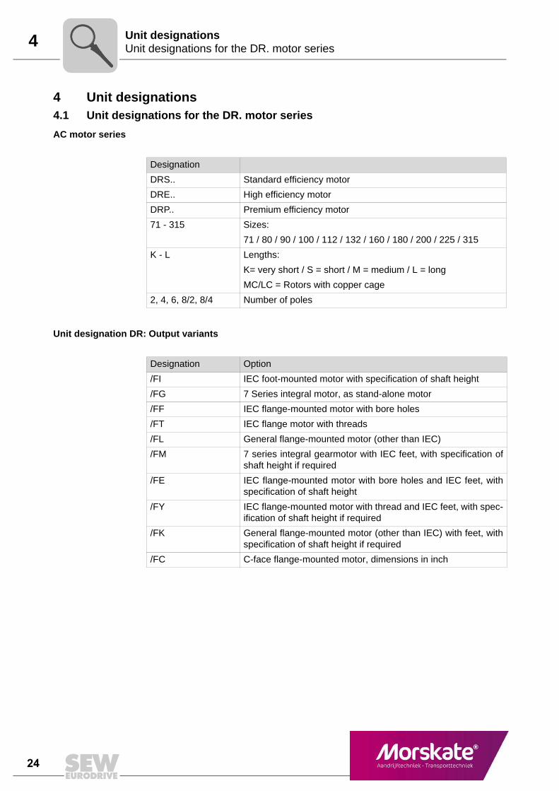
Designation
DRS.. Standard efficiency motor
DRE.. High efficiency motor
DRP.. Premium efficiency motor
71 - 315 Sizes:
71 / 80 / 90 / 100 / 112 / 132 / 160 / 180 / 200 / 225 / 315
K - L Lengths:
K= very short / S = short / M = medium / L = long
MC/LC = Rotors with copper cage
2, 4, 6, 8/2, 8/4 Number of poles
Designation Option
/FI IEC foot-mounted motor with specification of shaft height
/FG 7 Series integral motor, as stand-alone motor
/FF IEC flange-mounted motor with bore holes
/FT IEC flange motor with threads
/FL General flange-mounted motor (other than IEC)
/FM 7 series integral gearmotor with IEC feet, with specification ofshaft height if required
/FE IEC flange-mounted motor with bore holes and IEC feet, withspecification of shaft height
/FY IEC flange-mounted motor with thread and IEC feet, with spec-ification of shaft height if required
/FK General flange-mounted motor (other than IEC) with feet, withspecification of shaft height if required
/FC C-face flange-mounted motor, dimensions in inch
MOT1 – AC Motors 25
4
1
2
3
4
5
6
7
8
9
10
11
12
13
14
15
16
17
18
19
20
21
22
Unit designations for the DR. motor seriesUnit designations
Output types of the motors
Foot-mounted motor
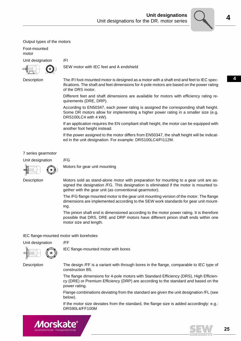
Unit designation /FI
SEW motor with IEC feet and A endshield
Description The /FI foot-mounted motor is designed as a motor with a shaft end and feet to IEC spec-ifications. The shaft and feet dimensions for 4-pole motors are based on the power ratingof the DRS motor.
Different feet and shaft dimensions are available for motors with efficiency rating re-quirements (DRE, DRP).
According to EN50347, each power rating is assigned the corresponding shaft height.Some DR motors allow for implementing a higher power rating in a smaller size (e.g.DRS100LC4 with 4 kW).
If an application requires the EN compliant shaft height, the motor can be equipped withanother foot height instead.
If the power assigned to the motor differs from EN50347, the shaft height will be indicat-ed in the unit designation. For example: DRS100LC4/FI112M.
7 series gearmotor
Unit designation /FG
Motors for gear unit mounting
Description Motors sold as stand-alone motor with preparation for mounting to a gear unit are as-signed the designation /FG. This designation is eliminated if the motor is mounted to-gether with the gear unit (as conventional gearmotor).
The /FG flange mounted motor is the gear unit mounting version of the motor. The flangedimensions are implemented according to the SEW work standards for gear unit mount-ing.
The pinion shaft end is dimensioned according to the motor power rating. It is thereforepossible that DRS, DRE and DRP motors have different pinion shaft ends within onemotor size and length.
IEC flange-mounted motor with boreholes
Unit designation /FF
IEC flange-mounted motor with bores
Description The design /FF is a variant with through bores in the flange, comparable to IEC type ofconstruction B5.
The flange dimensions for 4-pole motors with Standard Efficiency (DRS), High Efficien-cy (DRE) or Premium Efficiency (DRP) are according to the standard and based on thepower rating.
Flange combinations deviating from the standard are given the unit designation /FL (seebelow).
If the motor size deviates from the standard, the flange size is added accordingly: e.g.:DRS90L4/FF100M
26 MOT1 – AC Motors
4 Unit designations for the DR. motor seriesUnit designations
IEC flange-mounted motor with threads
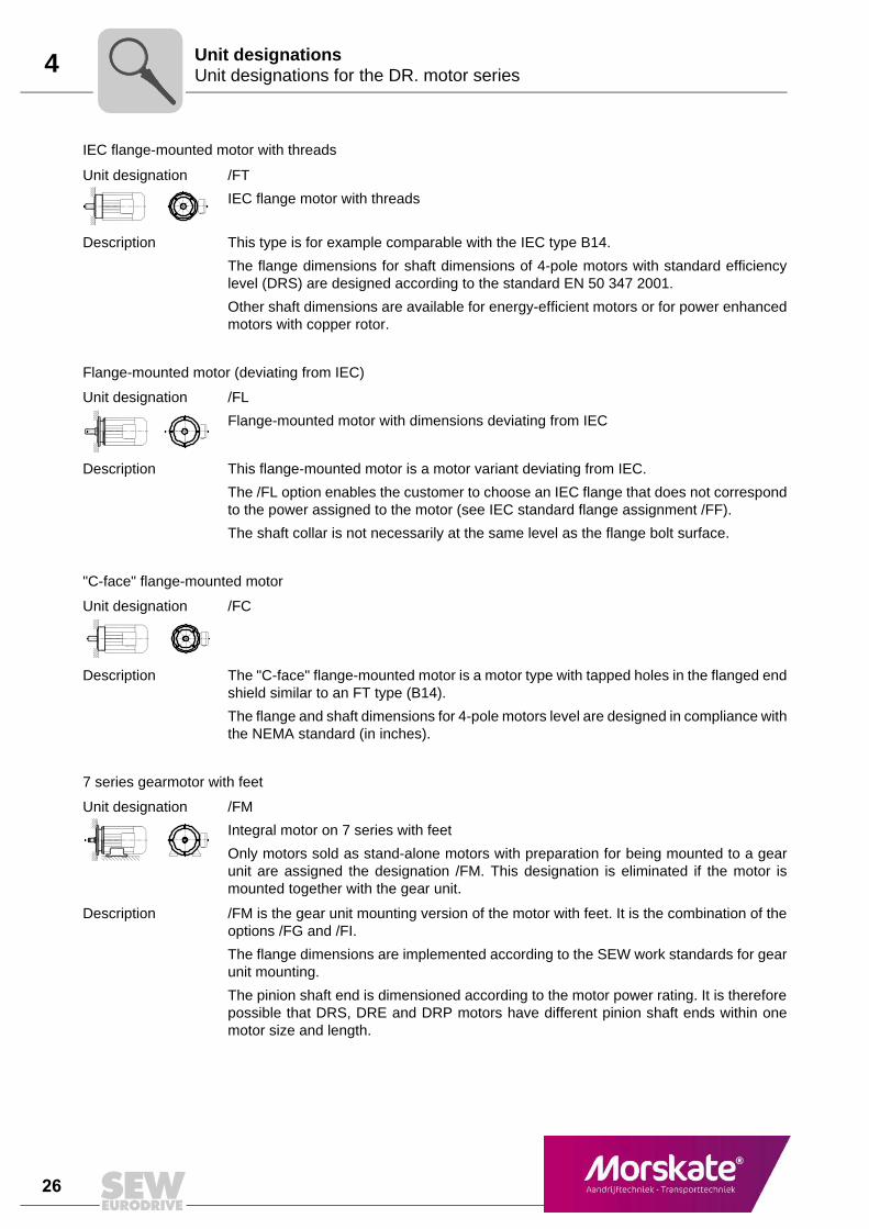
Unit designation /FT
IEC flange motor with threads
Description This type is for example comparable with the IEC type B14.
The flange dimensions for shaft dimensions of 4-pole motors with standard efficiencylevel (DRS) are designed according to the standard EN 50 347 2001.
Other shaft dimensions are available for energy-efficient motors or for power enhancedmotors with copper rotor.
Flange-mounted motor (deviating from IEC)
Unit designation /FL
Flange-mounted motor with dimensions deviating from IEC
Description This flange-mounted motor is a motor variant deviating from IEC.
The /FL option enables the customer to choose an IEC flange that does not correspondto the power assigned to the motor (see IEC standard flange assignment /FF).
The shaft collar is not necessarily at the same level as the flange bolt surface.
"C-face" flange-mounted motor
Unit designation /FC
Description The "C-face" flange-mounted motor is a motor type with tapped holes in the flanged endshield similar to an FT type (B14).
The flange and shaft dimensions for 4-pole motors level are designed in compliance withthe NEMA standard (in inches).
7 series gearmotor with feet
Unit designation /FM
Integral motor on 7 series with feet
Only motors sold as stand-alone motors with preparation for being mounted to a gearunit are assigned the designation /FM. This designation is eliminated if the motor ismounted together with the gear unit.
Description /FM is the gear unit mounting version of the motor with feet. It is the combination of theoptions /FG and /FI.
The flange dimensions are implemented according to the SEW work standards for gearunit mounting.
The pinion shaft end is dimensioned according to the motor power rating. It is thereforepossible that DRS, DRE and DRP motors have different pinion shaft ends within onemotor size and length.
MOT1 – AC Motors 27
4
1
2
3
4
5
6
7
8
9
10
11
12
13
14
15
16
17
18
19
20
21
22
Unit designations for the DR. motor seriesUnit designations
Foot-/flange-mounted motor
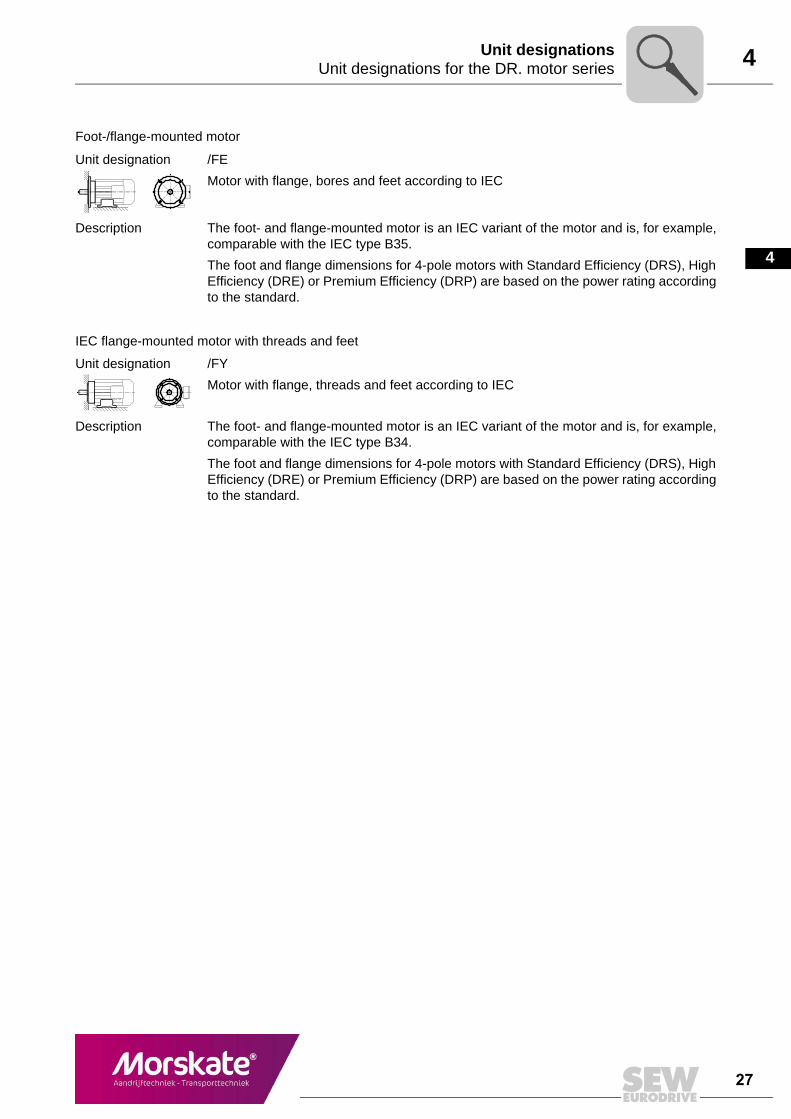
Unit designation /FE
Motor with flange, bores and feet according to IEC
Description The foot- and flange-mounted motor is an IEC variant of the motor and is, for example,comparable with the IEC type B35.
The foot and flange dimensions for 4-pole motors with Standard Efficiency (DRS), HighEfficiency (DRE) or Premium Efficiency (DRP) are based on the power rating accordingto the standard.
IEC flange-mounted motor with threads and feet
Unit designation /FY
Motor with flange, threads and feet according to IEC
Description The foot- and flange-mounted motor is an IEC variant of the motor and is, for example,comparable with the IEC type B34.
The foot and flange dimensions for 4-pole motors with Standard Efficiency (DRS), HighEfficiency (DRE) or Premium Efficiency (DRP) are based on the power rating accordingto the standard.
28 MOT1 – AC Motors
4 Unit designations for the DR. motor seriesUnit designations
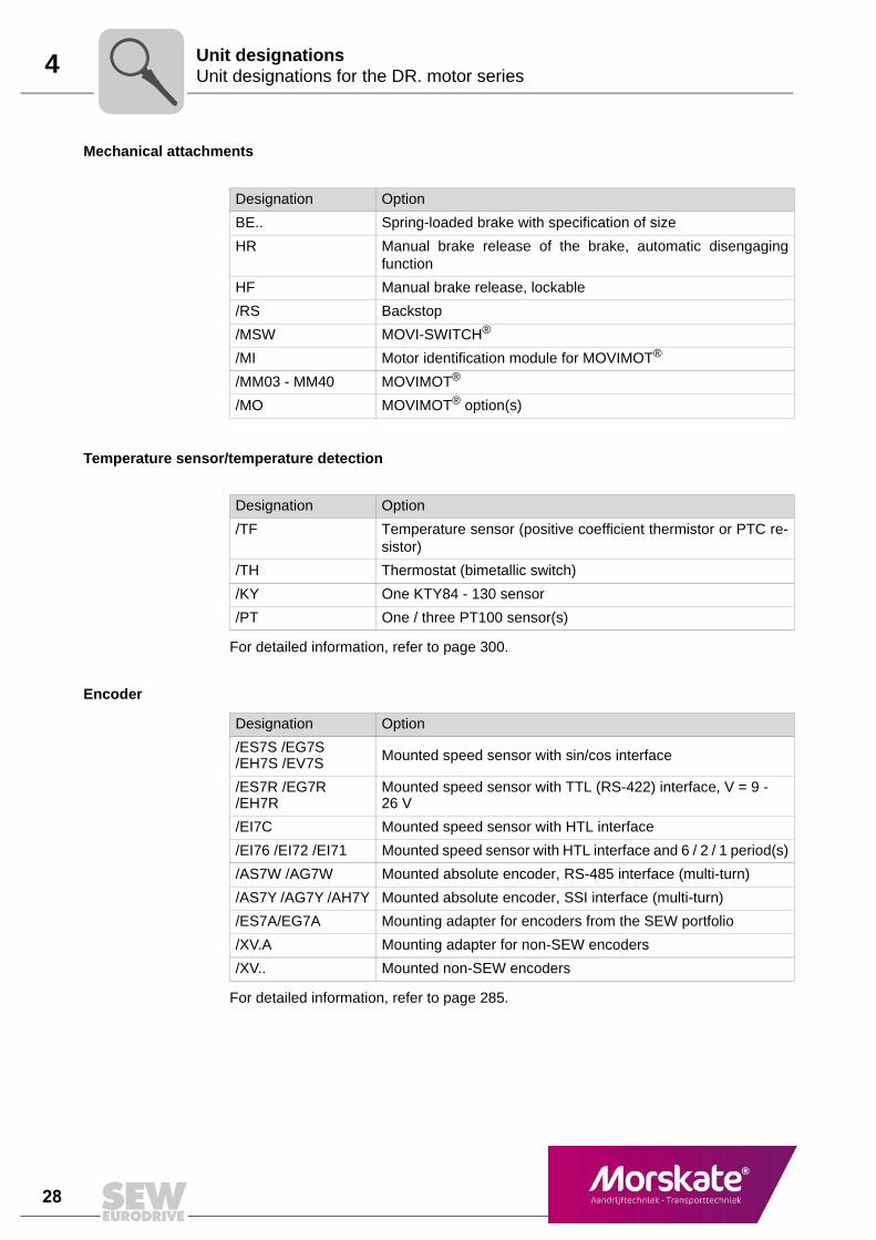
Mechanical attachments
Temperature sensor/temperature detection
For detailed information, refer to page 300.
Encoder
For detailed information, refer to page 285.
Designation Option
BE.. Spring-loaded brake with specification of size
HR Manual brake release of the brake, automatic disengagingfunction
HF Manual brake release, lockable
/RS Backstop
/MSW MOVI-SWITCH®
/MI Motor identification module for MOVIMOT®
/MM03 - MM40 MOVIMOT®
/MO MOVIMOT® option(s)
Designation Option
/TF Temperature sensor (positive coefficient thermistor or PTC re-sistor)
/TH Thermostat (bimetallic switch)
/KY One KTY84 - 130 sensor
/PT One / three PT100 sensor(s)
Designation Option
/ES7S /EG7S /EH7S /EV7S Mounted speed sensor with sin/cos interface
/ES7R /EG7R /EH7R
Mounted speed sensor with TTL (RS-422) interface, V = 9 - 26 V
/EI7C Mounted speed sensor with HTL interface
/EI76 /EI72 /EI71 Mounted speed sensor with HTL interface and 6 / 2 / 1 period(s)
/AS7W /AG7W Mounted absolute encoder, RS-485 interface (multi-turn)
/AS7Y /AG7Y /AH7Y Mounted absolute encoder, SSI interface (multi-turn)
/ES7A/EG7A Mounting adapter for encoders from the SEW portfolio
/XV.A Mounting adapter for non-SEW encoders
/XV.. Mounted non-SEW encoders
MOT1 – AC Motors 29
4
1
2
3
4
5
6
7
8
9
10
11
12
13
14
15
16
17
18
19
20
21
22
Unit designations for the DR. motor seriesUnit designations
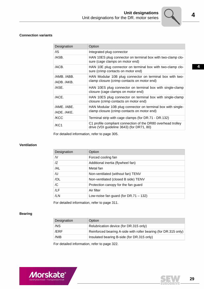
Connection variants
For detailed information, refer to page 305.
Ventilation
For detailed information, refer to page 311.
Bearing
For detailed information, refer to page 322.
Designation Option
/IS Integrated plug connector
/ASB. HAN 10ES plug connector on terminal box with two-clamp clo-sure (cage clamps on motor end)
/ACB. HAN 10E plug connector on terminal box with two-clamp clo-sure (crimp contacts on motor end)
/AMB. /ABB.
/ADB. /AKB.
HAN Modular 10B plug connector on terminal box with two-clamp closure (crimp contacts on motor end)
/ASE. HAN 10ES plug connector on terminal box with single-clampclosure (cage clamps on motor end)
/ACE. HAN 10ES plug connector on terminal box with single-clampclosure (crimp contacts on motor end)
/AME. /ABE.
/ADE. /AKE.
HAN Modular 10B plug connector on terminal box with single-clamp closure (crimp contacts on motor end)
/KCC Terminal strip with cage clamps (for DR.71 - DR.132)
/KC1 C1 profile compliant connection of the DR80 overhead trolley drive (VDI guideline 3643) (for DR71, 80)
Designation Option
/V Forced cooling fan
/Z Additional inertia (flywheel fan)
/AL Metal fan
/U Non-ventilated (without fan) TENV
/OL Non-ventilated (closed B side) TENV
/C Protection canopy for the fan guard
/LF Air filter
/LN Low-noise fan guard (for DR.71 – 132)
Designation Option
/NS Relubrication device (for DR.315 only)
/ERF Reinforced bearing A-side with roller bearing (for DR.315 only)
/NIB Insulated bearing B-side (for DR.315 only)
30 MOT1 – AC Motors
4 Unit designations for the DR. motor seriesUnit designations
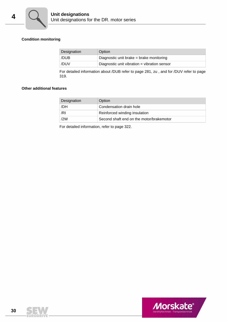
Condition monitoring
For detailed information about /DUB refer to page 281, zu , and for /DUV refer to page319.
Other additional features
For detailed information, refer to page 322.
Designation Option
/DUB Diagnostic unit brake = brake monitoring
/DUV Diagnostic unit vibration = vibration sensor
Designation Option
/DH Condensation drain hole
/RI Reinforced winding insulation
/2W Second shaft end on the motor/brakemotor
MOT1 – AC Motors 31
4
1
2
3
4
5
6
7
8
9
10
11
12
13
14
15
16
17
18
19
20
21
22
Serial numberUnit designations
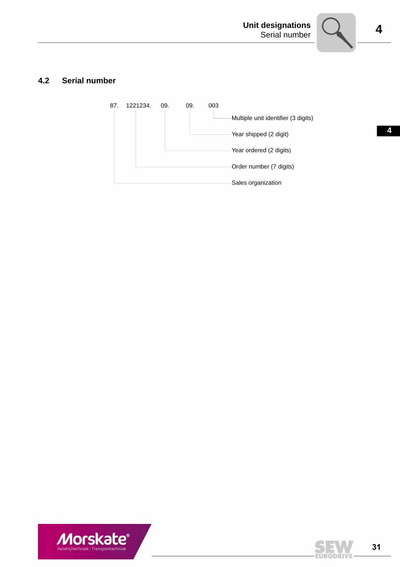
4.2 Serial number
87. 1221234. 09. 09. 003
Multiple unit identifier (3 digits)
Year shipped (2 digit)
Year ordered (2 digits)
Order number (7 digits)
Sales organization
32 MOT1 – AC Motors
4 Examples for the unit designation of DR series AC motorsUnit designations
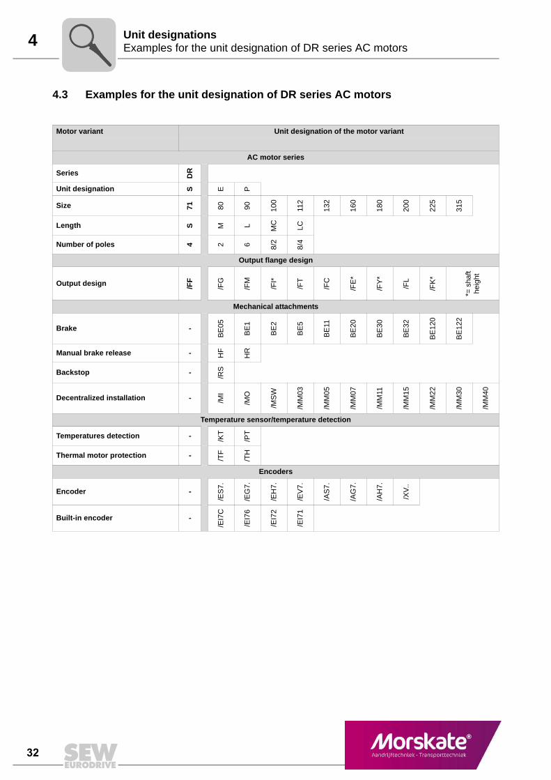
4.3 Examples for the unit designation of DR series AC motors
Motor variant Unit designation of the motor variant
AC motor series
Series DR
Unit designation S E P
Size 71 80 90 100
112
132
160
180
200
225
315
Length S M L MC
LC
Number of poles 4 2 6 8/2
8/4
Output flange design
Output design /FF
/FG
/FM
/FI*
/FT
/FC
/FE
*
/FY
*
/FL
/FK
*
*= s
haft
heig
ht
Mechanical attachments
Brake -
BE
05
BE
1
BE
2
BE
5
BE
11
BE
20
BE
30
BE
32
BE
120
BE
122
Manual brake release - HF
HR
Backstop - /RS
Decentralized installation - /MI
/MO
/MS
W
/MM
03
/MM
05
/MM
07
/MM
11
/MM
15
/MM
22
/MM
30
/MM
40
Temperature sensor/temperature detection
Temperatures detection - /KT
/PT
Thermal motor protection - /TF
/TH
Encoders
Encoder -
/ES
7.
/EG
7.
/EH
7.
/EV
7.
/AS
7.
/AG
7.
/AH
7.
/XV
..
Built-in encoder -
/EI7
C
/EI7
6
/EI7
2
/EI7
1
MOT1 – AC Motors 33
4
1
2
3
4
5
6
7
8
9
10
11
12
13
14
15
16
17
18
19
20
21
22
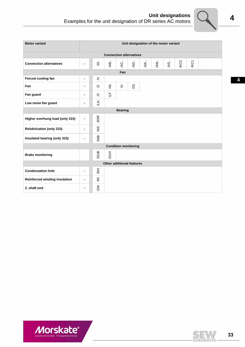
Examples for the unit designation of DR series AC motorsUnit designations
Connection alternatives
Connection alternatives - /IS /AB
..
/AC
..
/AD
..
/AK
..
/AM
..
/AS
..
/KC
C
/KC
1
Fan
Forced cooling fan - /V
Fan - /Z /AL
/U /OL
Fan guard - /C /LF
Low noise fan guard - /LN
Bearing
Higher overhung load (only 315) -
/ER
F
Relubrication (only 315) - /NS
Insulated bearing (only 315) -
/NIB
Condition monitoring
Brake monitoring
/DU
B
/DU
V
Other additional features
Condensation hole - /DH
Reinforced winding insulation - /RI
2. shaft end -
/2W
Motor variant Unit designation of the motor variant
34 MOT1 – AC Motors
4 Mounting position designations of the motorsUnit designations
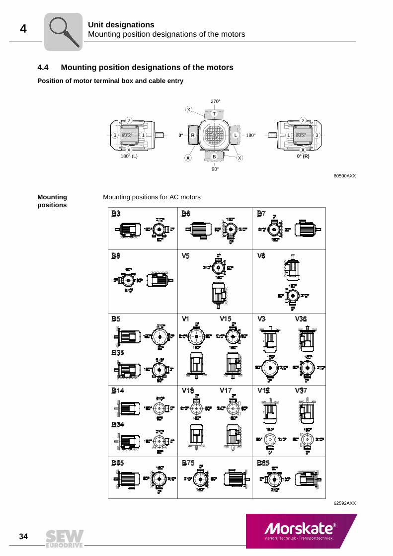
4.4 Mounting position designations of the motors
Position of motor terminal box and cable entry
Mounting positions
Mounting positions for AC motors
60500AXX
270°
90°
180°0°
T
B X
2
X
31LR
X
X
0° (R)
2
X
3 1
180° (L)
62592AXX