Embed Size (px)
Citation preview
C-SERIES S-SERIES Metric Machine
Screw Jacks
Power Jacks More than just a screw jack
02 www.powerjacks.com
03www.powerjacks.com 03www.powerjacks.com
Power Jacks are a manufacturer focused on providing customers with the best engineered solution for precision linear actuation, power transmission and mechanical jacking.
Our expertise has been built on a history of engineering craftsmanship and design dating back to 1903. The facility in Scotland is the UK’s largest screw jack manufacturing facility, that uses the latest engineering technologies to deliver quality products (BS EN ISO 9001:2008) that offer reliability, performance and economy.
Power Jacks is synonymous with screw jack technology and its development. We have been involved with Screw Jacks since the product was invented in the late 1930's and this gives us unparalleled experience in the design and manufacture of both standard and special designs.
Complimenting the screw jacks the Power Jacks portfolio also includes the design and manufacture of spiral bevel gearboxes, electric linear actuators and planetary roller screws. This enables us to offer our customers a complete linear motion and power transmission system and solution.
We know our customers demand our engineering expertise to help find a solution for their applications. We take pride in designing and delivering the best solution.This is what defines the Power Jacks range.
04 www.powerjacks.com
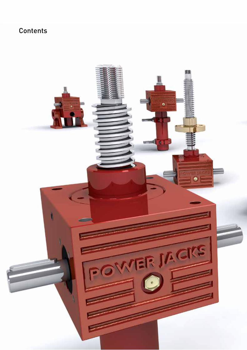
Contents
05www.powerjacks.com
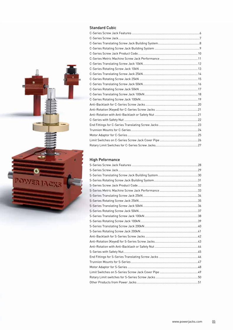
Standard CubicC-Series Screw Jack Features ................................................................................6
C-Series Screw Jack ................................................................................................7
C-Series Translating Screw Jack Building System .................................................8
C-Series Rotating Screw Jack Building System .....................................................9
C-Series Screw Jack Product Code .......................................................................10
C-Series Metric Machine Screw Jack Performance .............................................11
C-Series Translating Screw Jack 10kN .................................................................12
C-Series Rotating Screw Jack 10kN .....................................................................13
C-Series Translating Screw Jack 25kN .................................................................14
C-Series Rotating Screw Jack 25kN .....................................................................15
C-Series Translating Screw Jack 50kN .................................................................16
C-Series Rotating Screw Jack 50kN .....................................................................17
C-Series Translating Screw Jack 100kN ...............................................................18
C-Series Rotating Screw Jack 100kN....................................................................19
Anti-Backlash for C-Series Screw Jacks ..............................................................20
Anti-Rotation (Keyed) for C-Series Screw Jacks ..................................................21
Anti-Rotation with Anti-Backlash or Safety Nut ...................................................21
C-Series with Safety Nut .......................................................................................22
End Fittings for C-Series Translating Screw Jacks ..............................................23
Trunnion Mounts for C-Series ...............................................................................24
Motor Adaptor for C-Series ...................................................................................25
Limit Switches on C-Series Screw Jack Cover Pipe .............................................26
Rotary Limit Switches for C-Series Screw Jacks ..................................................27
High PeformanceS-Series Screw Jack Features ..............................................................................28
S-Series Screw Jack ..............................................................................................29
S-Series Translating Screw Jack Building System ...............................................30
S-Series Rotating Screw Jack Building System ....................................................31
S-Series Screw Jack Product Code .......................................................................32
S-Series Metric Machine Screw Jack Performance .............................................33
S-Series Translating Screw Jack 25kN .................................................................34
S-Series Rotating Screw Jack 25kN ......................................................................35
S-Series Translating Screw Jack 50kN .................................................................36
S-Series Rotating Screw Jack 50kN ......................................................................37
S-Series Translating Screw Jack 100kN ...............................................................38
S-Series Rotating Screw Jack 100kN ....................................................................39
S-Series Translating Screw Jack 200kN ...............................................................40
S-Series Rotating Screw Jack 200kN ....................................................................41
Anti-Backlash for S-Series Screw Jacks ..............................................................42
Anti-Rotation (Keyed) for S-Series Screw Jacks ...................................................43
Anti-Rotation with Anti-Backlash or Safety Nut ...................................................44
S-Series with Safety Nut ........................................................................................45
End Fittings for S-Series Translating Screw Jacks ..............................................46
Trunnion Mounts for S-Series ...............................................................................47
Motor Adaptor for S-Series ...................................................................................48
Limit Switches on S-Series Screw Jack Cover Pipe .............................................49
Rotary Limit switches for S-Series Screw Jacks ..................................................50
Other Products from Power Jacks ........................................................................51

Compact Durable Versatile Dynamic
Introducing the new C-Series Screw Jack range from Power Jacks, delivering new levels of versatility and quality.
Created by a team of experienced design engineers, the focus was to provide our customers with a new compact cubic Screw Jack, which offers versatility in mounting methods. In addition to this, we wanted to design a jack that had the perfect combination of excellent performance, a long lasting service life, durability, flexibility and an extensive accessory list. Perfect for industrial applications operating individually or as a multi unit jacking system.
Over 140 Million Standard Configurations.
4 Standard Screw Jack Designs• Standard• Anti-Backlash*• Anti-Rotation*• Safety Nut
Anti-Rotation can be combined with standard, anti-backlash and safety nut designs. * Translating screw configurations.
Gearbox Housing Is one of the most functional features of the C-Series screw jack. Using a rugged cast housing made of either a highly durable SG Iron or Aluminium. This provides a strong housing that firmly and accurately holds the gear set in a reservoir of chosen lubricant suited to the most industrial demands.
Reliable Worm Gear set Proven design used in millions of screw jacks.
Forced Grease Lubrication Of lead screw. Radial lubrication holes on the worm gear allow the worm shaft to force grease through directly onto the lead screw threads.This lowers friction and operating temperature while increasing life.
Corrosion Protection To suit all economic needs.• Standard Industrial Paint Finish• Arduous Environment Paint Finish• Customer Specified Paint• Plated Finish
06 www.powerjacks.com
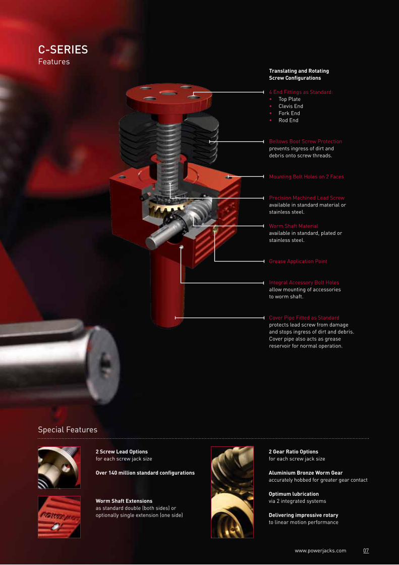
C-SERIESFeatures
Translating and Rotating Screw Configurations
4 End Fittings as Standard:• Top Plate• Clevis End• Fork End• Rod End
Bellows Boot Screw Protectionprevents ingress of dirt and debris onto screw threads.
Mounting Bolt Holes on 2 Faces
Precision Machined Lead Screwavailable in standard material or stainless steel.
Worm Shaft Materialavailable in standard, plated or stainless steel.
Grease Application Point
Integral Accessory Bolt Holesallow mounting of accessories to worm shaft.
Cover Pipe Fitted as Standardprotects lead screw from damage and stops ingress of dirt and debris. Cover pipe also acts as grease reservoir for normal operation.
Special Features
2 Screw Lead Options for each screw jack size
Over 140 million standard configurations
2 Gear Ratio Options for each screw jack size
Aluminium Bronze Worm Gear accurately hobbed for greater gear contact
Optimum lubricationvia 2 integrated systems
Delivering impressive rotaryto linear motion performance
Worm Shaft Extensions as standard double (both sides) or optionally single extension (one side)
07www.powerjacks.com
08 www.powerjacks.com
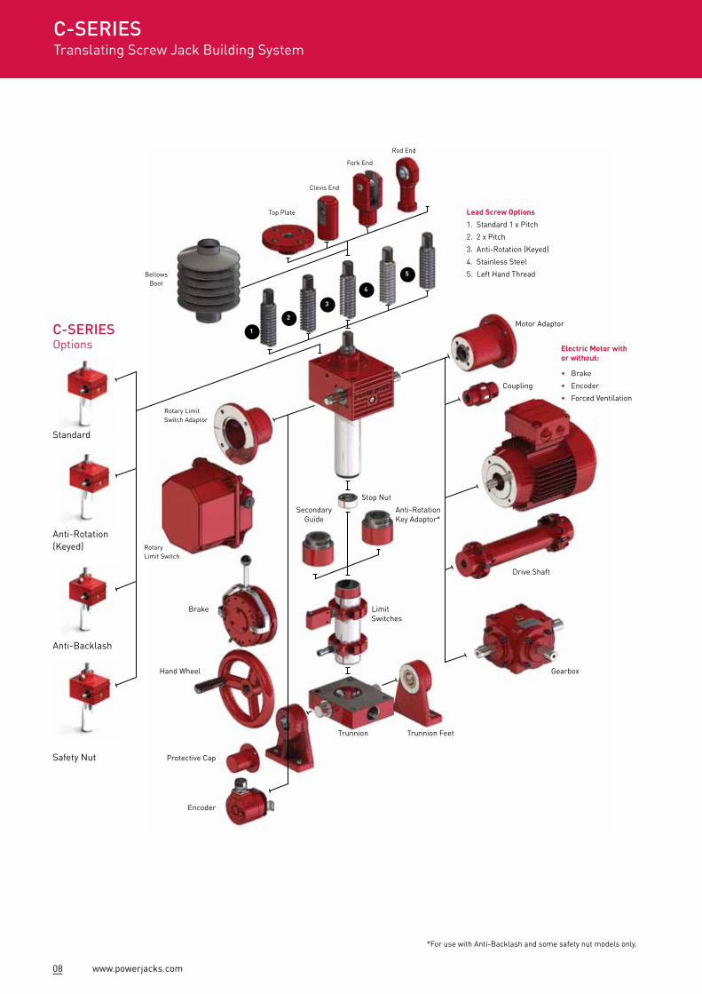
Lead Screw Options
1. Standard 1 x Pitch
2. 2 x Pitch
3. Anti-Rotation (Keyed)
4. Stainless Steel
5. Left Hand Thread
Electric Motor with or without:
• Brake
• Encoder
• Forced Ventilation
Motor Adaptor
Coupling
Drive Shaft
Gearbox
Stop Nut
Trunnion Feet
Limit Switches
Secondary Guide
Anti-Rotation Key Adaptor*
Rotary Limit Switch Adaptor
Bellows Boot
Top Plate
Clevis End
Fork End
Rod End
Rotary Limit Switch
Trunnion
Brake
Hand Wheel
Protective Cap
Encoder
*For use with Anti-Backlash and some safety nut models only.
C-SERIESOptions
Standard
Anti-Rotation (Keyed)
Anti-Backlash
Safety Nut
C-SERIESTranslating Screw Jack Building System
2
1
3
4
5
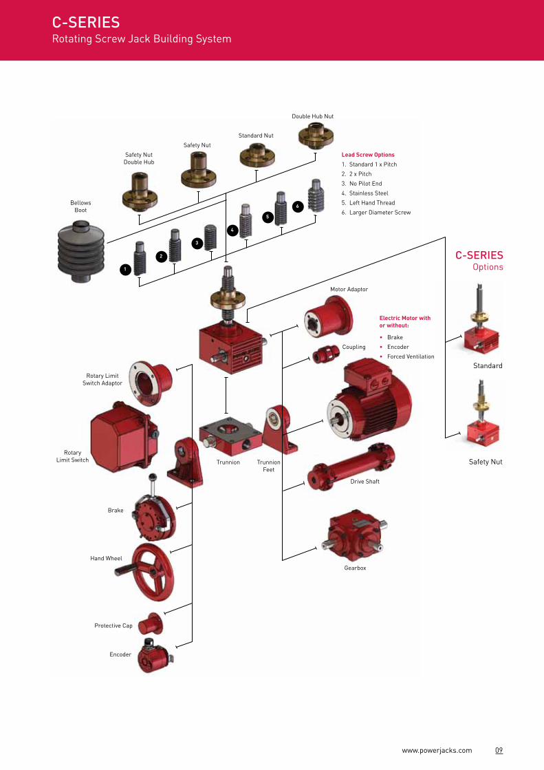
09www.powerjacks.com
Motor Adaptor
Coupling
Drive Shaft
Gearbox
Trunnion Feet
Rotary Limit Switch Adaptor
Bellows Boot
Safety Nut Double Hub
Safety Nut
Standard Nut
Double Hub Nut
Rotary Limit Switch Trunnion
Brake
Hand Wheel
Protective Cap
Encoder
Standard
Safety Nut
C-SERIESRotating Screw Jack Building System
C-SERIESOptions
Lead Screw Options
1. Standard 1 x Pitch
2. 2 x Pitch
3. No Pilot End
4. Stainless Steel
5. Left Hand Thread
6. Larger Diameter Screw
Electric Motor with or without:
• Brake
• Encoder
• Forced Ventilation
2
1
3
4
5
6

10 www.powerjacks.com
Example
Notes: #1. Rotating screw models only. #2. Trunnions on same side as worm shaft (standard). #3. Trunnions at 90° to worm shaft. #4. Standard right hand thread form. Worm shaft turns clockwise to extend screw. #5. Left hand thread form. Worm shaft turns anti-clockwise to extend screw. #6. Includes motor adaptor and coupling. IEC motor adaptor is standard. #7. Limit switch mounting included. #8. Design notes required to detail device/item specification. #9. Plain end “A” has same dimensions as “E-threaded end” except no thread form.
1 Screw Jack TypeC = C-Series Screw Jack
2 Screw TypeM = Machine Screw
3 Screw ConfigurationT = Translating ScrewR = Rotating Screw
4,5,6 Capacity (kN)010 = 10kN025 = 25kN050 = 50kN100 = 100kN
7,8,9,10 Stroke (mm)e.g.0750 = 750mm
11 End TypeE = Threaded EndC = ClevisT = Top PlateF = Fork EndR = Rod EndA = Plain End#9
P = Pilot End#1
N = No Pilot#1
12 Gearbox MountingB = Base MountT = Trunnion Mount
Standard#2
U = T + Trunnion FeetX = Trunnion Mount 90°#3
Y = X + Trunnion Feet
13 Lead Screw Pitch1 = Option 1 Lead#4
2 = Option 2 Lead#4
3 = Option 1 Left Hand#5
4 = Option 2 Left Hand#5
14 Gear Ratio1 = Option 1 Ratio2 = Option 2 Ratio
15 Features0 = NoneK = Anti-Rotation (keyed)C = Secondary GuideR = Anti-BacklashY = Anti-Backlash & Anti-Rotation (keyed)H = Double Hub Nut#1
16 Cover Pipe0 = Cover PipeN = No Cover Pipe
17 Stop Nut0 = No Stop NutP = Full Power Stop Nut
18 Safety Nut0 = No Safety NutT = Safety Nut TensionC = Safety Nut Compression
19 Worm Shaft Type0 = Standard MaterialN = Nickel PlatedC = Chrome PlatedS = Stainless Steel
20 Worm Shaft Ends0 = BothL = Left Hand Side OnlyR = Right Hand Side Only
21 Lead Screw Material0 = StandardS = Stainless SteelL = Large Diameter#1,#8
T = Large Diameter Stainless Steel #1, #8
22 Lead Screw Cover0 = NoneB = Bellows Boot (fabric)
23 Drive0 = Side Bolt Holes (both sides)M = Motor #6, #8
B = Brake Motor #6, #8
H = Hand Wheel1 = Side Bolt Holes - LHS2 = Side Bolt Hols - RHS3 = No Side Bolt HolesA = Motor Adaptor #6, #8
24 Limit Switch #7, #8
0 = NoneL = Electro-Mechanical Limit SwitchR = Rotary Cam Limit SwitchP = Proximity Sensor
25 Extra Design #8
0 = NoneS = Design Notes
1 2 3 4 5 6 7 8 9 10 11 12 13 14 15 16 17 18 19 20 21 22 23 24 25
C M T 0 2 5 0 7 5 0 T B 1 1 0 0 P T 0 0 0 B 3 P 0
C-SERIESScrew Jack Product Code
11www.powerjacks.com
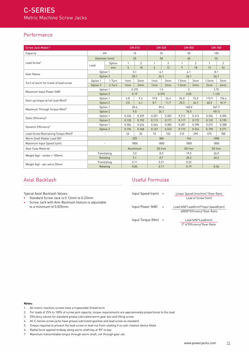
Performance
Notes:1. All metric machine screws have a trapezoidal thread form.2. For loads of 25% to 100% of screw jack capacity, torque requirements are approximately proportional to the load.3. Efficiency values for standard grease lubricated worm gear box and lifting screw.4. All C-Series screw jacks have grease lubricated gearbox and lead screw as standard.5. Torque required to prevent the lead screw or lead nut from rotating if no anti-rotation device fitted.6. Radial force applied midway along worm shaft key at 90º to key.7. Maximum transmittable torque through worm shaft, not through gear set.
Screw Jack Model 4 CM-010 CM-025 CM-050 CM-100
Capacity kN 10 25 50 100
Lead Screw1
Diameter (mm) 20 30 40 55
LeadOption 1 2 1 2 1 2 1 2
mm 5 10 6 12 9 18 12 24
Gear RatiosOption 1 5:1 6:1 6:1 8:1
Option 2 20:1 24:1 24:1 24:1
Turn of worm for travel of lead screwOption 1 1 Turn 1mm 2mm 1mm 2mm 1.5mm 3mm 1.5mm 3mm
Option 2 4 Turn 1mm 2mm 1mm 2mm 1.5mm 3mm 2mm 4mm
Maximum Input Power (kW)Option 1 0.375 1.5 3 3.75
Option 2 0.19 0.375 0.55 1.125
Start up torque at full load (Nm)2Option 1 6.8 9.4 19.8 26.4 56.0 76.0 115.9 156.6
Option 2 3.0 4.1 8.7 11.7 25.5 34.7 60.5 81.9
Maximum Through Torque (Nm)7Option 1 20.4 59.4 168.0 347.7
Option 2 9.0 26.1 76.5 181.5
Static Efficiency3Option 1 0.236 0.339 0.201 0.302 0.213 0.314 0.206 0.305
Option 2 0.133 0.192 0.113 0.171 0.117 0.172 0.132 0.195
Dynamic Efficiency3Option 1 0.306 0.424 0.264 0.383 0.281 0.398 0.272 0.388
Option 2 0.194 0.268 0.167 0.242 0.172 0.244 0.190 0.271
Lead Screw Restraining Torque (Nm)5 - 22 30 76 102 210 290 575 780
Worm Shaft Radial Load (N)6 325 380 740 1000
Maximum Input Speed (rpm) - 1800 1800 1800 1800
Gear Case Material Aluminium SG Iron SG Iron SG Iron
Weight (kg) – stroke = 150mmTranslating 3.0 8.3 19.5 36.0
Rotating 3.1 8.7 20.2 40.2
Weight (kg) – per extra 25mmTranslating 0.11 0.21 0.32
Rotating 0.05 0.11 0.19 0.36
C-SERIESMetric Machine Screw Jacks
Load (kN)*Lead(mm)*Input Speed(rpm) 60000*Efficiency*Gear Ratio
Input Speed (rpm) =
Input Power (kW) =
Input Torque (Nm) =
Linear Speed (mm/min) *Gear Ratio Lead of Screw (mm)
Axial Backlash
Typical Axial Backlash Values:• Standard Screw Jack is 0.12mm to 0.23mm• Screw Jack with Anti-Backlash feature is adjustable
to a minimum of 0.025mm.
Useful Formulae
Load (kN)*Lead(mm) 2* π*Efficiency*Gear Ratio
12 www.powerjacks.com
57
4 x Ø11
LHS
RHS
18S
TRO
KE
+ 4
4
3512
80
35
12
16
39
STR
OK
E
20
17
35
HUB FORBELLOWS
BOOT
(BE
LLO
WS
BO
OT
NO
T IN
CLU
DE
D)
7575
150
32.5
32.5
Ø14 (h8)
10078
4031.8331.75
8542
.5
6331
.5
2
5 x 5 x 25
M8 x 1.2515 DEEP
(BOTH SIDES)RHS
LHS
(SN
)S
TRO
KE
+ 5
7518
130
37.5
39
34
20
24
46
STR
OK
E
M12 x 1.75
M6 x 112 DEEP
(CLO
SE
D H
EIG
HT)
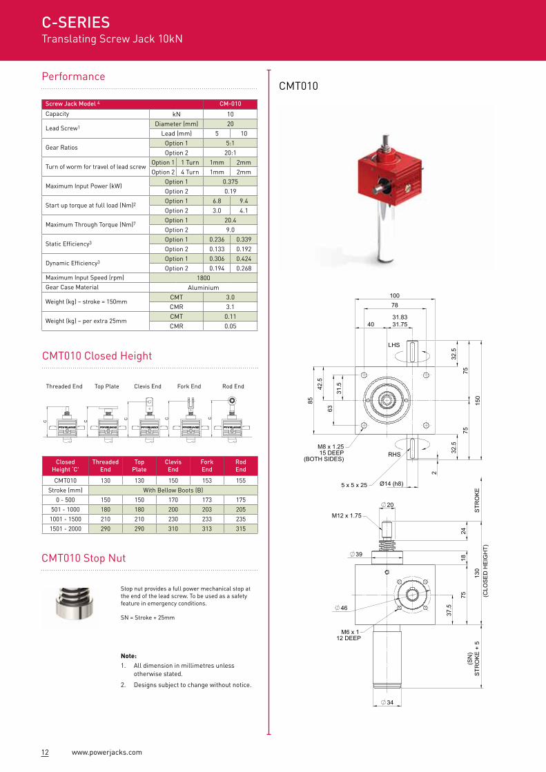
CMT010 Stop Nut
Stop nut provides a full power mechanical stop at the end of the lead screw. To be used as a safety feature in emergency conditions.
SN = Stroke + 25mm
Performance
CMT010 Closed Height
CMT010
C C C C C
Screw Jack Model 4 CM-010
Capacity kN 10
Lead Screw1 Diameter (mm) 20Lead (mm) 5 10
Gear RatiosOption 1 5:1Option 2 20:1
Turn of worm for travel of lead screwOption 1 1 Turn 1mm 2mmOption 2 4 Turn 1mm 2mm
Maximum Input Power (kW)Option 1 0.375Option 2 0.19
Start up torque at full load (Nm)2 Option 1 6.8 9.4Option 2 3.0 4.1
Maximum Through Torque (Nm)7 Option 1 20.4Option 2 9.0
Static Efficiency3 Option 1 0.236 0.339Option 2 0.133 0.192
Dynamic Efficiency3 Option 1 0.306 0.424Option 2 0.194 0.268
Maximum Input Speed (rpm) 1800Gear Case Material Aluminium
Weight (kg) – stroke = 150mmCMT 3.0CMR 3.1
Weight (kg) – per extra 25mmCMT 0.11CMR 0.05
ClosedHeight ‘C'
ThreadedEnd
Top Plate
ClevisEnd
ForkEnd
RodEnd
CMT010 130 130 150 153 155
Stroke (mm) With Bellow Boots (B)
0 - 500 150 150 170 173 175
501 - 1000 180 180 200 203 205
1001 - 1500 210 210 230 233 235
1501 - 2000 290 290 310 313 315
C-SERIESTranslating Screw Jack 10kN
Threaded End Top Plate Clevis End Fork End Rod End
Note:1. All dimension in millimetres unless
otherwise stated.
2. Designs subject to change without notice.
13www.powerjacks.com
Accessories & Options
Rotary Limit Switch Adaptor
Anti-BacklashEnd Fittings
Anti-Rotation (Keyed)
Limit Switches
Double Hub Nut
DrivesSafety Nut
Motor Adaptors
Secondary Guide
Trunnion Mounts
Corrosion Protection
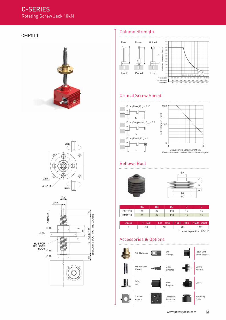
ØA ØB ØC D E
CMT010 30 39 110 15 15
CMR010 35 39 110 15 15
ØA
ØBØC
DF
E
*control tapes fitted ØC=110
Critical Screw Speed
Bellows Boot
100 200 300 500400 600 700 800 900
50 100 150 200 300250 350 400 450
FIXED/GUIDED
PINNED/PINNED
FIXED/FREE
00 100 200 300 400 500 600 700 800 900 1000 1100 1200
1200
PE
RM
ISS
IBLE
CO
MP
RE
SS
IVE
LO
AD
(K
G)
1100
1000
900
800
700
600
500
400
300
200
100COLUMN LENGTH (mm)
Column Strength
L
L
L
Fixed/Free, Fcs = 0.15
Fixed/Supported, Fcs = 0.7
Fixed/Fixed, Fcs = 1
100
Cri
tical
Spe
ed (r
pm)
1000
101 10
L L L
CMR010
Stroke 1 – 500 501 – 1000 1001 – 1500 1500 – 2000
F 30 60 90 170*
C-SERIESRotating Screw Jack 10kN
Unsupported Screw Length (m)(Based on both ends fixed and 80% of the critical speed)
Free Pinned Guided
Fixed Pinned Fixed
57
4 x Ø11
LHS
RHS
18S
TRO
KE
+ 4
4
3512
80
35
12
16
39
STR
OK
E
20
17
35
HUB FORBELLOWS
BOOT
(BE
LLO
WS
BO
OT
NO
T IN
CLU
DE
D)
7575
150
32.5
32.5
Ø14 (h8)
10078
4031.8331.75
8542
.5
6331
.5
2
5 x 5 x 25
M8 x 1.2515 DEEP
(BOTH SIDES)RHS
LHS
(SN
)S
TRO
KE
+ 5
7518
130
37.5
39
34
20
24
46
STR
OK
E
M12 x 1.75
M6 x 112 DEEP
(CLO
SE
D H
EIG
HT)
14 www.powerjacks.com
HUB FORBELLOWS
BOOT
41
8223
30
145
(SN
)S
TRO
KE
+ 5
46
49
46
30
STR
OK
E
M6 x 114 DEEP
M20 x 2.5
Ø16 (h8) 2
37.5
0
9090
180
105
52.5
0
81
40.5
0130
106
5443.2943.24
37.5
0
5 x 5 x 30
LHS
RHSM10 x 1.515 DEEP
(BOTH SIDES)
23S
TRO
KE
+ 6
0
20
40
90
46
15
40
30
25
STR
OK
E
20
40
(BE
LLO
WS
BO
OT
NO
T IN
CLU
DE
D)
65
RHS
LHS
4 x Ø13.5
(CLO
SE
D H
EIG
HT)
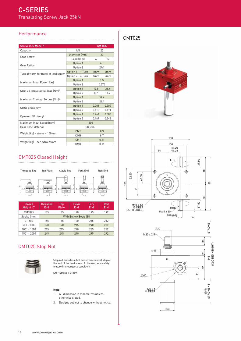
Performance
CMT025 Closed Height
CMT025
ClosedHeight ‘C'
ThreadedEnd
Top Plate
ClevisEnd
ForkEnd
RodEnd
CMT025 145 145 170 195 192
Stroke (mm) With Bellow Boots (B)
0 - 500 165 165 190 215 212
501 - 1000 190 190 215 240 237
1001 - 1500 215 215 240 265 262
1501 - 2000 245 245 270 295 292
Screw Jack Model 4 CM-025
Capacity kN 25
Lead Screw1Diameter (mm) 30
Lead (mm) 6 12
Gear RatiosOption 1 6:1
Option 2 24:1
Turn of worm for travel of lead screwOption 1 1 Turn 1mm 2mm
Option 2 4 Turn 1mm 2mm
Maximum Input Power (kW)Option 1 1.5
Option 2 0.375
Start up torque at full load (Nm)2Option 1 19.8 26.4
Option 2 8.7 11.7
Maximum Through Torque (Nm)7Option 1 59.4
Option 2 26.1
Static Efficiency3Option 1 0.201 0.302
Option 2 0.113 0.171
Dynamic Efficiency3Option 1 0.264 0.383
Option 2 0.167 0.242
Maximum Input Speed (rpm) 1800
Gear Case Material SG Iron
Weight (kg) – stroke = 150mmCMT 8.3
CMR 8.7
Weight (kg) – per extra 25mmCMT 0.21
CMR 0.11
C-SERIESTranslating Screw Jack 25kN
CMT025 Stop Nut
Stop nut provides a full power mechanical stop at the end of the lead screw. To be used as a safety feature in emergency conditions.
SN = Stroke + 21mm
C C C C C
Threaded End Top Plate Clevis End Fork End Rod End
Note:1. All dimension in millimetres unless
otherwise stated.
2. Designs subject to change without notice.
15www.powerjacks.com
Accessories & Options
Rotary Limit Switch Adaptor
Anti-BacklashEnd Fittings
Anti-Rotation (Keyed)
Limit Switches
Double Hub Nut
DrivesSafety Nut
Motor Adaptors
Secondary Guide
Trunnion Mounts
Corrosion Protection
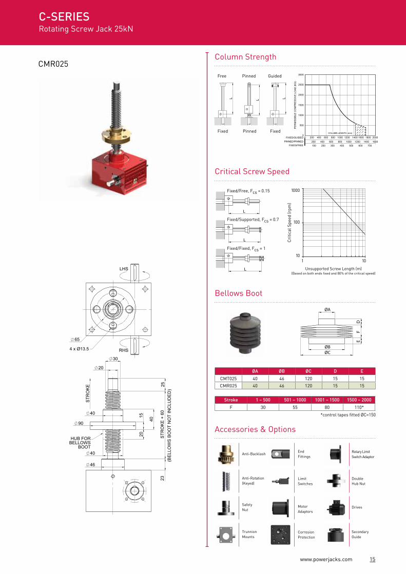
CMR025
200 400 600 800 1000 1200 1400100 200 300 400 500 600 700
FIXED/GUIDEDPINNED/PINNED
FIXED/FREE
00 200 400 600 800 1000 1200 1400 1600 1800 2000
3000
PER
MIS
SIBL
E C
OM
PRES
SIVE
LO
AD (K
G)
2500
2000
1500
1000
500
1600
COLUMN LENGTH (mm)
Column Strength
Cri
tical
Spe
ed (r
pm)
1
100
1000
1010
C-SERIESRotating Screw Jack 25kN
ØA
ØBØC
DF
E
Critical Screw Speed
Bellows Boot
L
L
L
Fixed/Free, Fcs = 0.15
Fixed/Supported, Fcs = 0.7
Fixed/Fixed, Fcs = 1
L L L
ØA ØB ØC D E
CMT025 40 46 120 15 15
CMR025 40 46 120 15 15
Stroke 1 – 500 501 – 1000 1001 – 1500 1500 – 2000
F 30 55 80 110*
*control tapes fitted ØC=150
Unsupported Screw Length (m)(Based on both ends fixed and 80% of the critical speed)
Free Pinned Guided
Fixed Pinned Fixed
HUB FORBELLOWS
BOOT
41
8223
30
145
(SN
)S
TRO
KE
+ 5
46
49
46
30
STR
OK
E
M6 x 114 DEEP
M20 x 2.5
Ø16 (h8) 2
37.5
0
9090
180
105
52.5
0
81
40.5
0
130
106
5443.2943.24
37.5
0
5 x 5 x 30
LHS
RHSM10 x 1.515 DEEP
(BOTH SIDES)
23S
TRO
KE
+ 6
0
20
40
90
46
15
40
30
25
STR
OK
E
20
40
(BE
LLO
WS
BO
OT
NO
T IN
CLU
DE
D)
65
RHS
LHS
4 x Ø13.5
(CLO
SE
D H
EIG
HT)
16 www.powerjacks.com
LHS
(SN
)S
TRO
KE
- 5
58.5
117
32
195
35
60
61
61
40
STR
OK
E
(CLO
SE
D H
EIG
HT)
M8 x 1.2516 DEEP
M24 x 3
115
115
230
42.5
42.5
3
Ø19 (h8)
7855.5855.63
150
180
145
72.5
115
57.5
M12 X 1.7516 DEEP
(BOTH SIDES) 6 x 6 x 35RHS
32S
TRO
KE
+ 8
030
25
40
55
115
20 65
60S
TRO
KE
55 20
(BE
LLO
WS
BO
OT
NO
T IN
CLU
DE
D)
HUB FORBELLOWS
BOOT
85
4 x Ø18
LHS
RHS
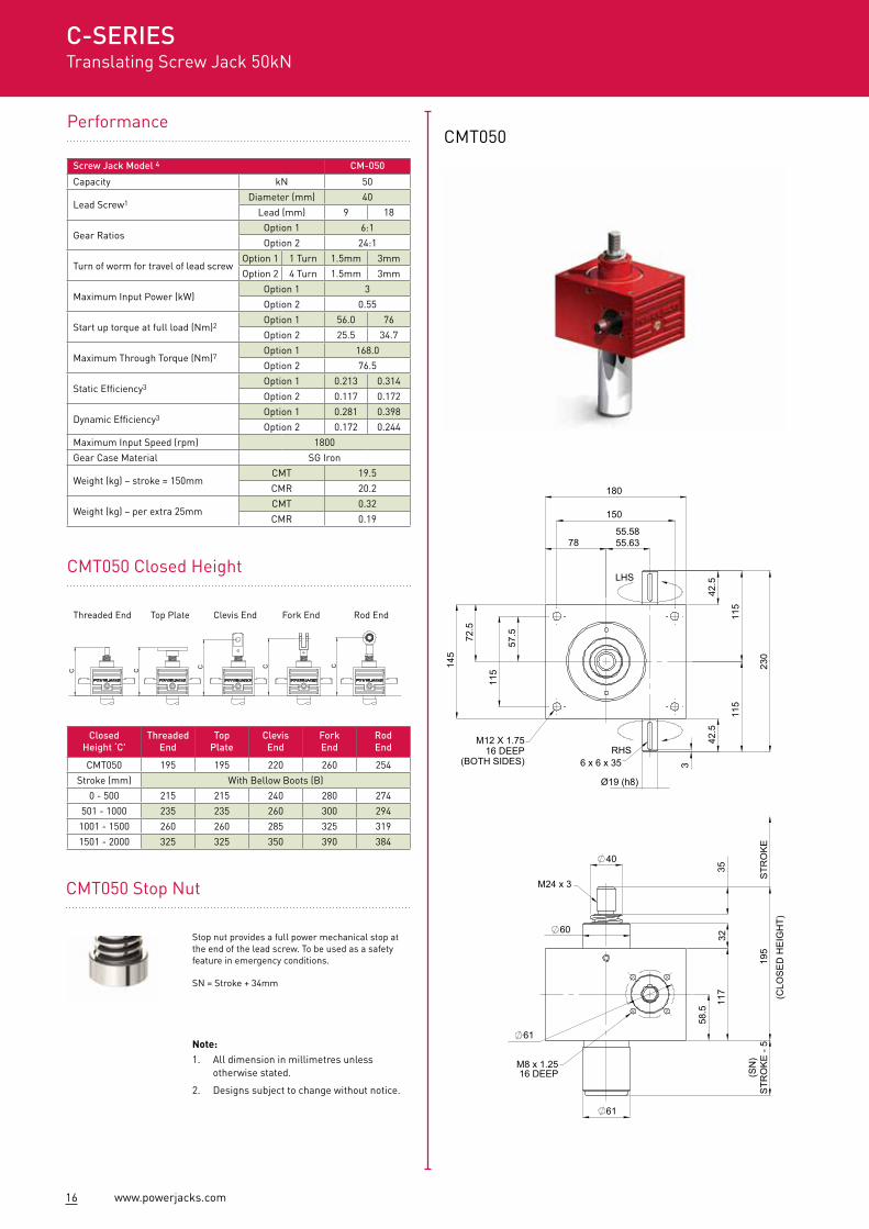
PerformanceCMT050
ClosedHeight ‘C'
ThreadedEnd
Top Plate
ClevisEnd
ForkEnd
RodEnd
CMT050 195 195 220 260 254
Stroke (mm) With Bellow Boots (B)
0 - 500 215 215 240 280 274
501 - 1000 235 235 260 300 294
1001 - 1500 260 260 285 325 319
1501 - 2000 325 325 350 390 384
Screw Jack Model 4 CM-050
Capacity kN 50
Lead Screw1Diameter (mm) 40
Lead (mm) 9 18
Gear RatiosOption 1 6:1
Option 2 24:1
Turn of worm for travel of lead screwOption 1 1 Turn 1.5mm 3mm
Option 2 4 Turn 1.5mm 3mm
Maximum Input Power (kW)Option 1 3
Option 2 0.55
Start up torque at full load (Nm)2Option 1 56.0 76
Option 2 25.5 34.7
Maximum Through Torque (Nm)7Option 1 168.0
Option 2 76.5
Static Efficiency3Option 1 0.213 0.314
Option 2 0.117 0.172
Dynamic Efficiency3Option 1 0.281 0.398
Option 2 0.172 0.244
Maximum Input Speed (rpm) 1800
Gear Case Material SG Iron
Weight (kg) – stroke = 150mmCMT 19.5
CMR 20.2
Weight (kg) – per extra 25mmCMT 0.32
CMR 0.19
C-SERIESTranslating Screw Jack 50kN
CMT050 Closed Height
CMT050 Stop Nut
Stop nut provides a full power mechanical stop at the end of the lead screw. To be used as a safety feature in emergency conditions.
SN = Stroke + 34mm
C C C C C
Threaded End Top Plate Clevis End Fork End Rod End
Note:1. All dimension in millimetres unless
otherwise stated.
2. Designs subject to change without notice.
17www.powerjacks.com
Accessories & Options
Rotary Limit Switch Adaptor
Anti-BacklashEnd Fittings
Anti-Rotation (Keyed)
Limit Switches
Double Hub Nut
DrivesSafety Nut
Motor Adaptors
Secondary Guide
Trunnion Mounts
Corrosion Protection
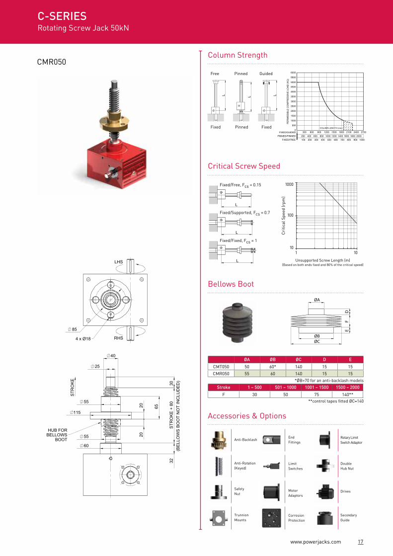
CMR050
200 400 800600 1000 1200 16001400 1800 2000100 200 300 400 500 600 700 800 900 1000
FIXED/GUIDEDPINNED/PINNED
FIXED/FREE
00 300 600 900 1200 1500 1800 2100 2400 2700
6000
PER
MIS
SIBL
E C
OM
PRES
SIVE
LO
AD (K
G) 5500
4000
3500
3000
2500
2000
1500
1000
500COLUMN LENGTH (mm)
5000
4500
100
Cri
tical
Spe
ed (r
pm)
1000
101 10
C-SERIESRotating Screw Jack 50kN
Column Strength
ØA
ØBØC
DF
E
Critical Screw Speed
Bellows Boot
L
L
L
Fixed/Free, Fcs = 0.15
Fixed/Supported, Fcs = 0.7
Fixed/Fixed, Fcs = 1
L L L
**control tapes fitted ØC=140
ØA ØB ØC D E
CMT050 50 60* 140 15 15
CMR050 55 60 140 15 15
Stroke 1 – 500 501 – 1000 1001 – 1500 1500 – 2000
F 30 50 75 140**
*ØB=70 for an anti-backlash models
Unsupported Screw Length (m)(Based on both ends fixed and 80% of the critical speed)
Free Pinned Guided
Fixed Pinned Fixed
LHS
(SN
)S
TRO
KE
- 5
58.5
117
32
195
35
60
61
61
40
STR
OK
E
(CLO
SE
D H
EIG
HT)
M8 x 1.2516 DEEP
M24 x 3
115
115
230
42.5
42.5
3
Ø19 (h8)
7855.5855.63
150
180
145
72.5
115
57.5
M12 X 1.7516 DEEP
(BOTH SIDES) 6 x 6 x 35RHS
32S
TRO
KE
+ 8
030
25
40
55
115
20 65
60
STR
OK
E
55 20
(BE
LLO
WS
BO
OT
NO
T IN
CLU
DE
D)
HUB FORBELLOWS
BOOT
85
4 x Ø18
LHS
RHS
18 www.powerjacks.com
160
40S
TRO
KE
+ 1
0050
80
85
25
75
35
STR
OK
E
55
80 20
(BE
LLO
WS
BO
OT
NO
T IN
CLU
DE
D)
HUB FORBELLOWS
BOOT
120
LHS
RHS4 x Ø22
80
160
40
40
250
(SN
)S
TRO
KE
- 15
85
70
73
55
STR
OK
E(C
LOS
ED
HE
IGH
T)
M36 x 4
M8 x 1.2514 DEEP
66.06
280
57.5
57.5
140
140
200
166
83 66.00
165
82.5
131
65.5
Ø25 (h8)
4
LHS
RHS
8 x 7 x 40
M20 x 2.530 DEEP
(BOTH SIDES)
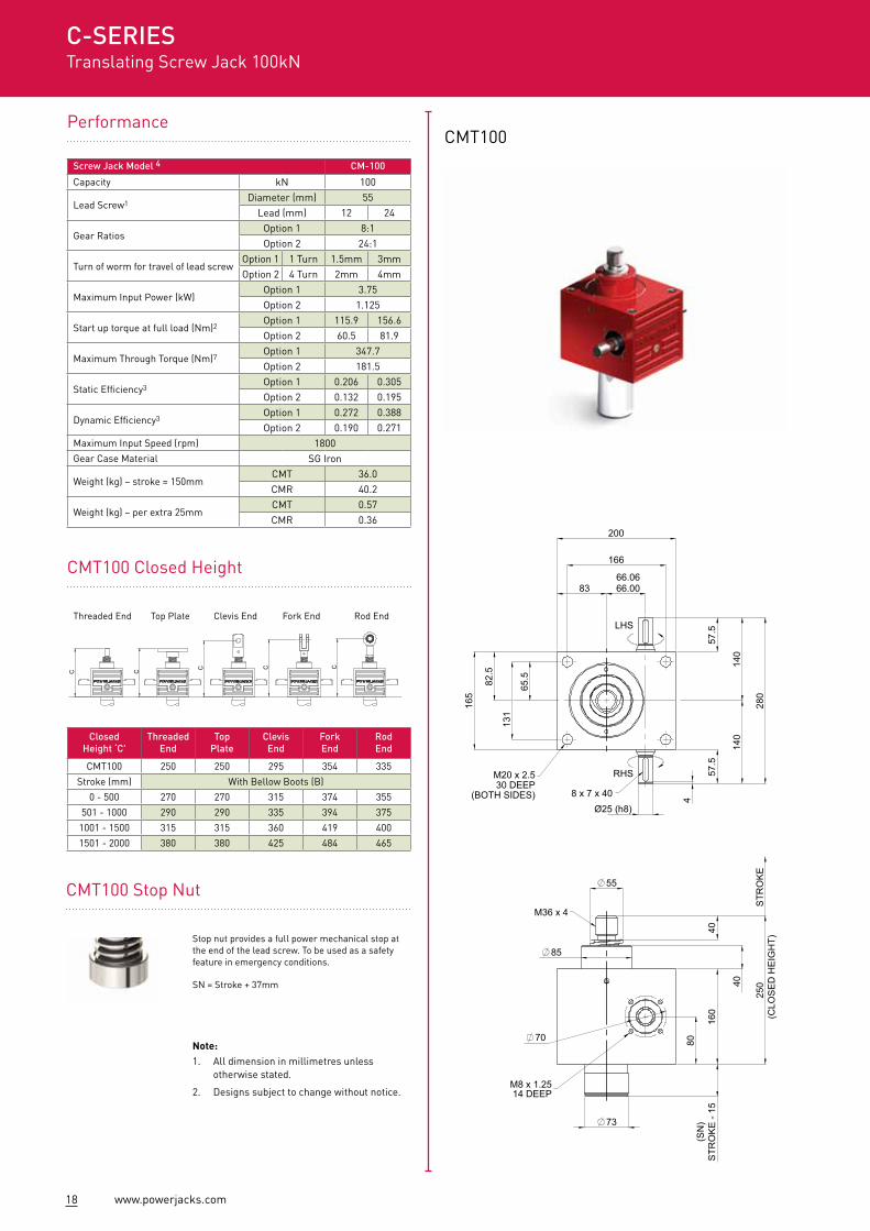
CMT100
ClosedHeight ‘C'
ThreadedEnd
Top Plate
ClevisEnd
ForkEnd
RodEnd
CMT100 250 250 295 354 335
Stroke (mm) With Bellow Boots (B)
0 - 500 270 270 315 374 355
501 - 1000 290 290 335 394 375
1001 - 1500 315 315 360 419 400
1501 - 2000 380 380 425 484 465
Screw Jack Model 4 CM-100
Capacity kN 100
Lead Screw1Diameter (mm) 55
Lead (mm) 12 24
Gear RatiosOption 1 8:1Option 2 24:1
Turn of worm for travel of lead screwOption 1 1 Turn 1.5mm 3mmOption 2 4 Turn 2mm 4mm
Maximum Input Power (kW)Option 1 3.75Option 2 1.125
Start up torque at full load (Nm)2Option 1 115.9 156.6Option 2 60.5 81.9
Maximum Through Torque (Nm)7Option 1 347.7Option 2 181.5
Static Efficiency3Option 1 0.206 0.305Option 2 0.132 0.195
Dynamic Efficiency3Option 1 0.272 0.388Option 2 0.190 0.271
Maximum Input Speed (rpm) 1800Gear Case Material SG Iron
Weight (kg) – stroke = 150mmCMT 36.0CMR 40.2
Weight (kg) – per extra 25mmCMT 0.57CMR 0.36
C-SERIESTranslating Screw Jack 100kN
Performance
CMT100 Closed Height
CMT100 Stop Nut
Stop nut provides a full power mechanical stop at the end of the lead screw. To be used as a safety feature in emergency conditions.
SN = Stroke + 37mm
C C C C C
Threaded End Top Plate Clevis End Fork End Rod End
Note:1. All dimension in millimetres unless
otherwise stated.
2. Designs subject to change without notice.