Embed Size (px)
Citation preview
19www.powerjacks.com
Accessories & Options
Rotary Limit Switch Adaptor
Anti-BacklashEnd Fittings
Anti-Rotation (Keyed)
Limit Switches
Double Hub Nut
DrivesSafety Nut
Motor Adaptors
Secondary Guide
Trunnion Mounts
Corrosion Protection
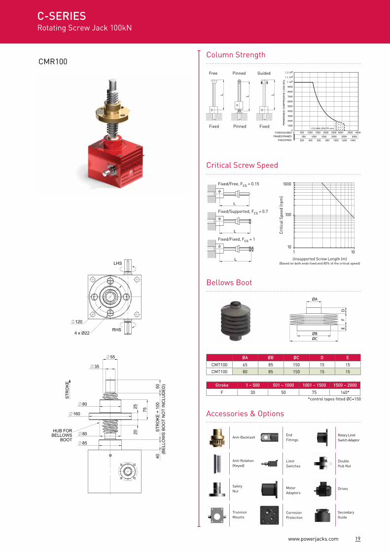
CMR100
ØA ØB ØC D E
CMT100 65 85 150 15 15
CMT100 80 85 150 15 15
200 400 600 800 1000 1200 1400
FIXED/GUIDEDPINNED/PINNED
FIXED/FREE
00 500 1000 1500 2000 2500 3000
500 1000 1500 2000 2500 3000
3500 4000
1.2.104
PER
MIS
SIBL
E C
OM
PRES
SIVE
LO
AD (K
G)
1.1.104
1.104
9000
8000
7000
6000
5000
4000
3000
2000
1000COLUMN LENGTH (mm)
100
Cri
tical
Spe
ed (r
pm)
1000
101 10
Stroke 1 – 500 501 – 1000 1001 – 1500 1500 – 2000
F 30 50 75 140*
C-SERIESRotating Screw Jack 100kN
Column Strength
ØA
ØBØC
DF
E
Critical Screw Speed
Bellows Boot
L
L
L
Fixed/Free, Fcs = 0.15
Fixed/Supported, Fcs = 0.7
Fixed/Fixed, Fcs = 1
L L L
*control tapes fitted ØC=150
Unsupported Screw Length (m)(Based on both ends fixed and 80% of the critical speed)
Free Pinned Guided
Fixed Pinned Fixed
160
40S
TRO
KE
+ 1
0050
80
85
25
75
35
STR
OK
E
55
80 20
(BE
LLO
WS
BO
OT
NO
T IN
CLU
DE
D)
HUB FORBELLOWS
BOOT
120
LHS
RHS4 x Ø22
80
160
40
40
250
(SN
)S
TRO
KE
- 15
85
70
73
55
STR
OK
E(C
LOS
ED
HE
IGH
T)
M36 x 4
M8 x 1.2514 DEEP
66.06
280
57.5
57.5
140
140
200
166
83 66.00
165
82.5
131
65.5
Ø25 (h8)
4
LHS
RHS
8 x 7 x 40
M20 x 2.530 DEEP
(BOTH SIDES)
20 www.powerjacks.com
The dimensions for these screw jacks are the same as the standard units except those detailed below.
Note: Efficiency values for standard grease lubricated worm gear box and lifting screw.
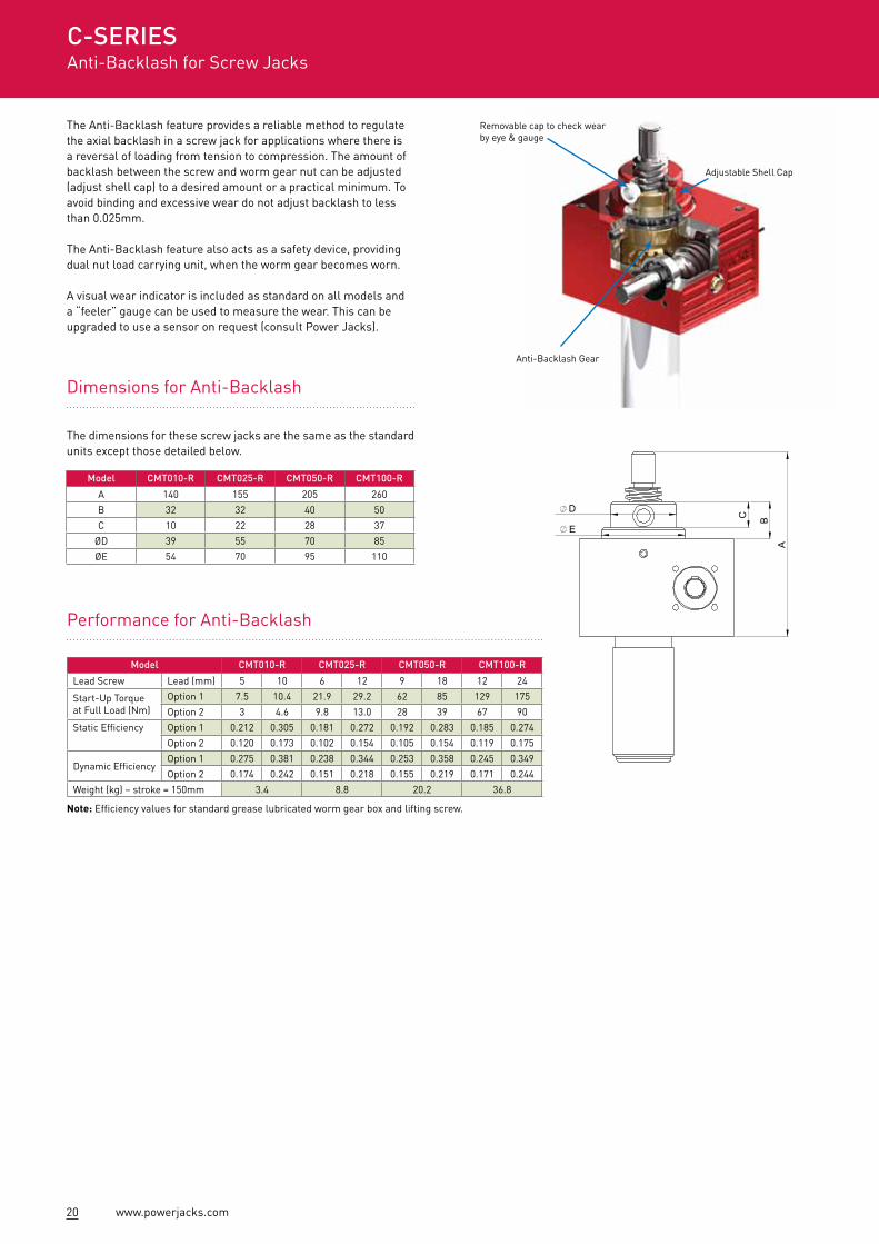
Removable cap to check wear by eye & gauge
Adjustable Shell Cap
Anti-Backlash Gear
The Anti-Backlash feature provides a reliable method to regulate the axial backlash in a screw jack for applications where there is a reversal of loading from tension to compression. The amount of backlash between the screw and worm gear nut can be adjusted (adjust shell cap) to a desired amount or a practical minimum. To avoid binding and excessive wear do not adjust backlash to less than 0.025mm.
The Anti-Backlash feature also acts as a safety device, providing dual nut load carrying unit, when the worm gear becomes worn.
A visual wear indicator is included as standard on all models and a “feeler” gauge can be used to measure the wear. This can be upgraded to use a sensor on request (consult Power Jacks).
A
E
D
BC
Dimensions for Anti-Backlash
Model CMT010-R CMT025-R CMT050-R CMT100-R
A 140 155 205 260
B 32 32 40 50
C 10 22 28 37
ØD 39 55 70 85
ØE 54 70 95 110
Model CMT010-R CMT025-R CMT050-R CMT100-R
Lead Screw Lead (mm) 5 10 6 12 9 18 12 24
Start-Up Torque at Full Load (Nm)
Option 1 7.5 10.4 21.9 29.2 62 85 129 175
Option 2 3 4.6 9.8 13.0 28 39 67 90
Static Efficiency Option 1 0.212 0.305 0.181 0.272 0.192 0.283 0.185 0.274
Option 2 0.120 0.173 0.102 0.154 0.105 0.154 0.119 0.175
Dynamic EfficiencyOption 1 0.275 0.381 0.238 0.344 0.253 0.358 0.245 0.349
Option 2 0.174 0.242 0.151 0.218 0.155 0.219 0.171 0.244
Weight (kg) – stroke = 150mm 3.4 8.8 20.2 36.8
C-SERIESAnti-Backlash for Screw Jacks
Performance for Anti-Backlash
21www.powerjacks.com
Model CMT010-Y CMT025-Y CMT050-Y CMT100-Y
Lead Screw Lead (mm) 5 10 6 12 9 18 12 24
Start-Up Torque at Full Load (Nm)
Option 1 8.3 11.5 24.8 33.0 65.6 89.3 136 184
Option 2 3.8 5.3 10.3 13.7 30.0 40.9 70.3 95.2
Static EfficiencyOption 1 0.201 0.290 0.172 0.258 0.182 0.269 0.176 0.263
Option 2 0.114 0.164 0.097 0.146 0.100 0.146 0.113 0.166
Dynamic EfficiencyOption 1 0.261 0.362 0.226 0.330 0.240 0.340 0.233 0.332
Option 2 0.165 0.230 0.143 0.207 0.147 0.208 0.162 0.232
Weight (kg) – stroke = 150mm 3.15 8.75 20 37.3
Model CMT010-KT CMT025-KT CMT050-KT CMT100-KT
F Stroke +5 Stroke +10 Stroke +15 Stroke +20
G 35 50 59 57
ØH 45 55 70 89Detail A = Same as standard CMT screw jack
Load Direction - Compression (C)Model CMT010-KC CMT025-KC CMT050-KC CMT100-KC
F Stroke +5 Stroke +10 Stroke +15 Stroke +20G 30 35.5 40 48
ØH 42.5 60 75 90Detail A = Same as standard safety nut screw jack with compression load (Refer P22)
GD
ETA
IL A
F
H
TC
kN
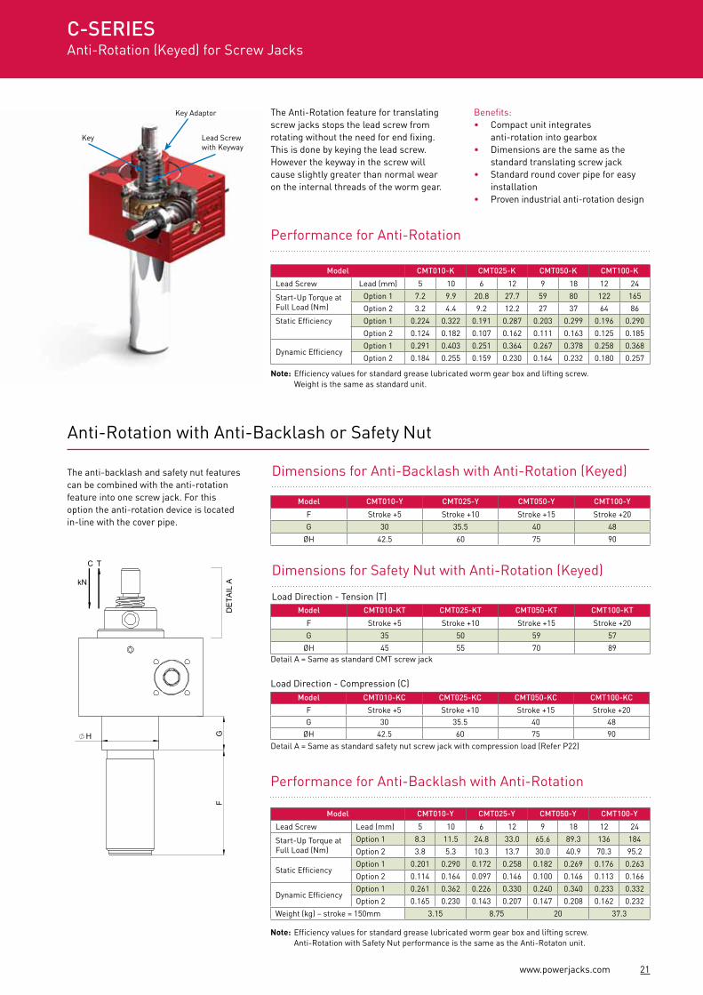
The Anti-Rotation feature for translating screw jacks stops the lead screw from rotating without the need for end fixing. This is done by keying the lead screw. However the keyway in the screw will cause slightly greater than normal wear on the internal threads of the worm gear.
Benefits:• Compact unit integrates
anti-rotation into gearbox• Dimensions are the same as the
standard translating screw jack• Standard round cover pipe for easy
installation• Proven industrial anti-rotation design
The anti-backlash and safety nut features can be combined with the anti-rotation feature into one screw jack. For this option the anti-rotation device is located in-line with the cover pipe.
Anti-Rotation with Anti-Backlash or Safety Nut
Performance for Anti-Rotation
Note: Efficiency values for standard grease lubricated worm gear box and lifting screw. Weight is the same as standard unit.
Dimensions for Anti-Backlash with Anti-Rotation (Keyed)
Dimensions for Safety Nut with Anti-Rotation (Keyed)
Load Direction - Tension (T)
Performance for Anti-Backlash with Anti-Rotation
Note: Efficiency values for standard grease lubricated worm gear box and lifting screw. Anti-Rotation with Safety Nut performance is the same as the Anti-Rotaton unit.
Key Adaptor
Lead Screw with Keyway
Key
Model CMT010-K CMT025-K CMT050-K CMT100-K
Lead Screw Lead (mm) 5 10 6 12 9 18 12 24
Start-Up Torque at Full Load (Nm)
Option 1 7.2 9.9 20.8 27.7 59 80 122 165
Option 2 3.2 4.4 9.2 12.2 27 37 64 86
Static Efficiency Option 1 0.224 0.322 0.191 0.287 0.203 0.299 0.196 0.290
Option 2 0.124 0.182 0.107 0.162 0.111 0.163 0.125 0.185
Dynamic EfficiencyOption 1 0.291 0.403 0.251 0.364 0.267 0.378 0.258 0.368
Option 2 0.184 0.255 0.159 0.230 0.164 0.232 0.180 0.257
Model CMT010-Y CMT025-Y CMT050-Y CMT100-Y
F Stroke +5 Stroke +10 Stroke +15 Stroke +20
G 30 35.5 40 48
ØH 42.5 60 75 90
C-SERIESAnti-Rotation (Keyed) for Screw Jacks
22 www.powerjacks.com
A
E
H
D
BC
G
DE
TAIL
AD
ETA
IL B
FS
TRO
KE
+ A
F
D
E
B
C
G
kN
Power Jacks metric machine screw jacks can be fitted with a safety nut, which provides 2 safety roles:
1. In the event of excessive wear on the nut thread the load will be transferred from the standard nut to the safety nut. This will also provide visual wear indication as the gap between the safety nut decreases to zero as the standard lifting nut wears.
2. In the unlikely event of catastrophic nut thread failure the safety nut will sustain the load. The safety of industrial and human cargo is therefore improved.
There are several configurations for each safety nut device as they only work in one load direction. For this reason when ordering please supply a sketch of your application showing load directions.
C = Load direction - CompressionT = Load direction - Tension
Translating Screw Jack with Safety Nut
The dimensions for these screw jacks are the same as the standard units except those detailed below.
Load Direction - Compression (C)Model CMT010-C CMT025-C CMT050-C CMT100-C
A 140 155 205 250
B 32 33 40 40
C 10 22 28 40
ØD 39 55 70 85
ØE 54 70 95 85
Dimension F, G, ØH not applicableDetail A = As per tableDetail B = Same as standard CMT screw jack
Load Direction - Tension (T)Model CMT010-T CMT025-T CMT050-T CMT100-T
F Stroke + 5 Stroke + 10 Stroke + 15 Stroke + 20
G 35 50 59 57
ØH 45 55 70 89
Dimension A, B, C, ØD, ØE not applicableDetail A = Same as standard CMT screw jackDetail B = As per table
Model CMT010 CMT025 CMT050 CMT100
Wieght (kg) 2.9 8.0 18.6 34.7
Rotating Screw Jack with Saftey Nut
The dimensions for these screw jacks are the same as the standard units except those detailed below. A bellows boot hub can be provided on the flanged half of the safety nut.
Model CMR010 CMR025 CMR050 CMR100
A Stroke +76 Stroke +95 Stroke +140 Stroke +170
B 66.5 75 125 145
C 30 33.5 58 67
D 12 15 20 25
ØE 80 90 115 160
ØF 35 40 55 80
G4 x Ø11
Ø57 PCD4 x Ø13.5Ø65 PCD
4 x Ø18Ø85 PCD
4 x Ø22Ø120 PCD
PCD = Pitch Circle DiameterNut must be orientated correctly for load direction
Model CMR010 CMR025 CMR050 CMR100
Weight (kg) 3.3 9.0 21.1 42.2
C-SERIESwith Safety Nut
kN
kN kN
C
C
TT
23www.powerjacks.com
A
G
BC
F
D
EJ
H
K
CB
C
DE
F
A
J
L
K
G
H
CD
E
B
H
FA G
J
C
D
AB
G
H
FE
A
G
BC
F
D
EJ
H
K
CB
C
DE
F
A
J
L
K
G
H
CD
E
BH
FA G
J
C
D
AB
G
H
FE
A
G
BC
F
D
EJ
H
K
CB
C
DE
F
A
J
L
K
G
H
CD
EB
H
FA G
J
C
D
AB
G
H
FE
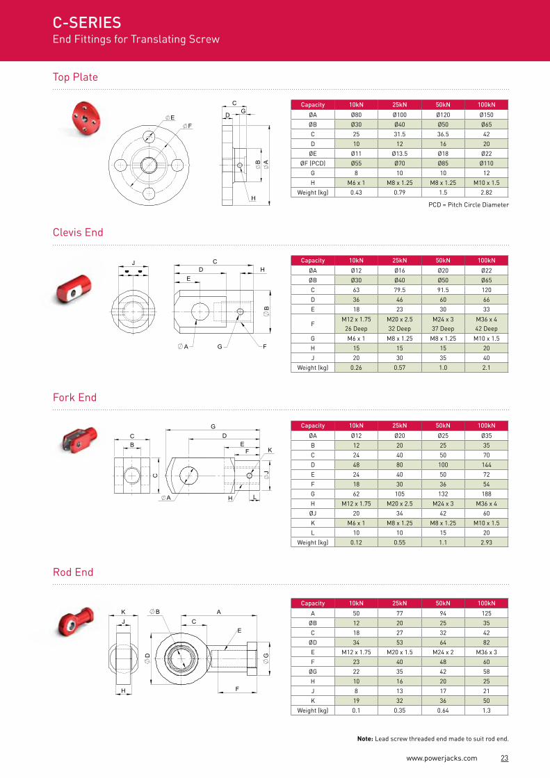
Top Plate
A
G
BC
F
D
EJ
H
K
CB
C
DE
F
A
J
L
K
G
H
CD
E
B
H
FA G
J
C
D
AB
G
H
FE
Fork End
Rod End
Clevis End
Capacity 10kN 25kN 50kN 100kN
ØA Ø80 Ø100 Ø120 Ø150
ØB Ø30 Ø40 Ø50 Ø65
C 25 31.5 36.5 42
D 10 12 16 20
ØE Ø11 Ø13.5 Ø18 Ø22
ØF (PCD) Ø55 Ø70 Ø85 Ø110
G 8 10 10 12
H M6 x 1 M8 x 1.25 M8 x 1.25 M10 x 1.5
Weight (kg) 0.43 0.79 1.5 2.82
Capacity 10kN 25kN 50kN 100kN
ØA Ø12 Ø16 Ø20 Ø22
ØB Ø30 Ø40 Ø50 Ø65
C 63 79.5 91.5 120
D 36 46 60 66
E 18 23 30 33
FM12 x 1.75
26 DeepM20 x 2.532 Deep
M24 x 337 Deep
M36 x 442 Deep
G M6 x 1 M8 x 1.25 M8 x 1.25 M10 x 1.5
H 15 15 15 20
J 20 30 35 40
Weight (kg) 0.26 0.57 1.0 2.1
Capacity 10kN 25kN 50kN 100kN
ØA Ø12 Ø20 Ø25 Ø35
B 12 20 25 35
C 24 40 50 70
D 48 80 100 144
E 24 40 50 72
F 18 30 36 54
G 62 105 132 188
H M12 x 1.75 M20 x 2.5 M24 x 3 M36 x 4
ØJ 20 34 42 60
K M6 x 1 M8 x 1.25 M8 x 1.25 M10 x 1.5
L 10 10 15 20
Weight (kg) 0.12 0.55 1.1 2.93
Note: Lead screw threaded end made to suit rod end.
C-SERIESEnd Fittings for Translating Screw
PCD = Pitch Circle Diameter
Capacity 10kN 25kN 50kN 100kN
A 50 77 94 125
ØB 12 20 25 35
C 18 27 32 42
ØD 34 53 64 82
E M12 x 1.75 M20 x 1.5 M24 x 2 M36 x 3
F 23 40 48 60
ØG 22 35 42 58
H 10 16 20 25
J 8 13 17 21
K 19 32 36 50
Weight (kg) 0.1 0.35 0.64 1.3
24 www.powerjacks.com
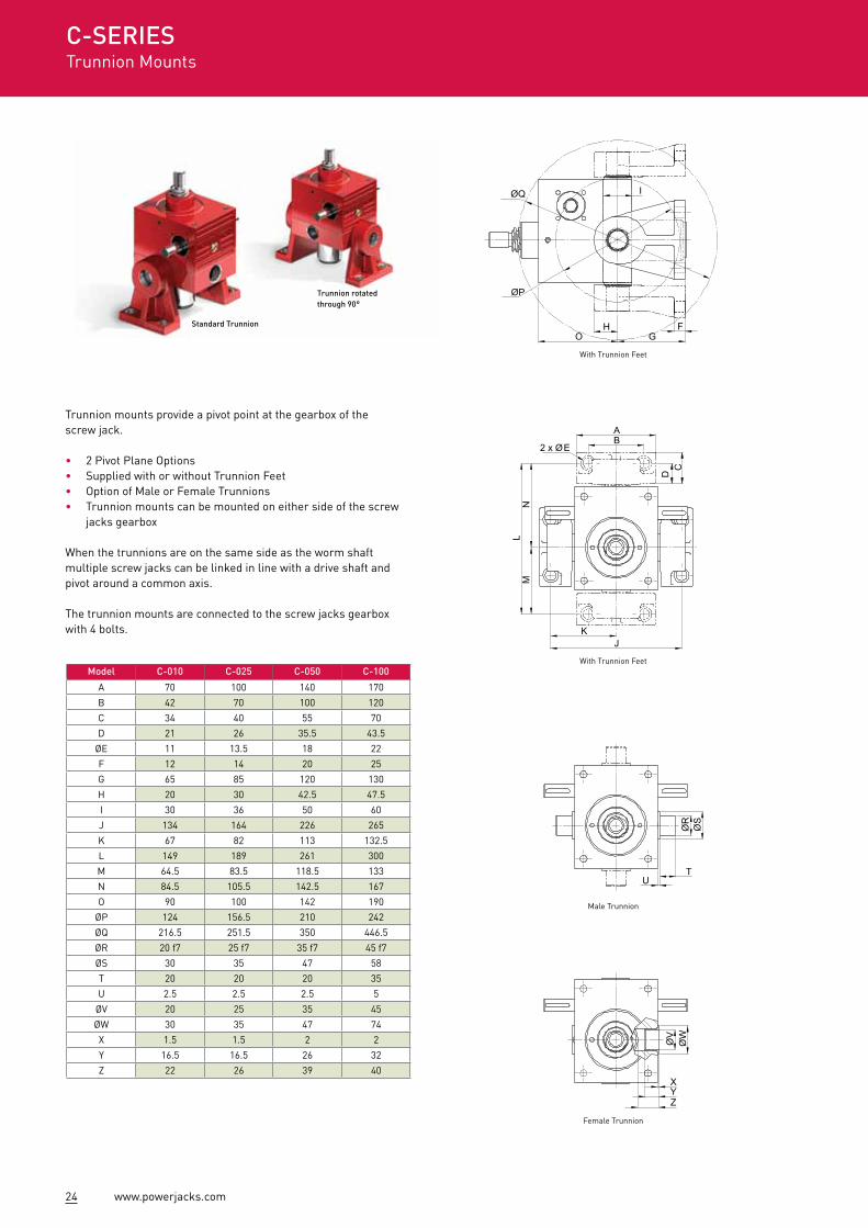
Model C-010 C-025 C-050 C-100
A 70 100 140 170
B 42 70 100 120
C 34 40 55 70
D 21 26 35.5 43.5
ØE 11 13.5 18 22
F 12 14 20 25
G 65 85 120 130
H 20 30 42.5 47.5
I 30 36 50 60
J 134 164 226 265
K 67 82 113 132.5
L 149 189 261 300
M 64.5 83.5 118.5 133
N 84.5 105.5 142.5 167
O 90 100 142 190
ØP 124 156.5 210 242
ØQ 216.5 251.5 350 446.5
ØR 20 f7 25 f7 35 f7 45 f7
ØS 30 35 47 58
T 20 20 20 35
U 2.5 2.5 2.5 5
ØV 20 25 35 45
ØW 30 35 47 74
X 1.5 1.5 2 2
Y 16.5 16.5 26 32
Z 22 26 39 40
Trunnion mounts provide a pivot point at the gearbox of the screw jack.
• 2 Pivot Plane Options• Supplied with or without Trunnion Feet• Option of Male or Female Trunnions• Trunnion mounts can be mounted on either side of the screw
jacks gearbox
When the trunnions are on the same side as the worm shaft multiple screw jacks can be linked in line with a drive shaft and pivot around a common axis.
The trunnion mounts are connected to the screw jacks gearbox with 4 bolts.
E
ØR
TU
ØS
Y
ØV
ØW
X
Z
A
CD
2 x ØB
L
JK
NM
FGO
I
H
ØQ
ØP
With Trunnion Feet
E
ØR
TU
ØS
YØ
VØ
W
X
Z
A
CD
2 x ØB
L
JK
NM
FGO
I
H
ØQ
ØP
Male Trunnion
E
ØR
TU
ØS
Y
ØV
ØW
X
Z
A
CD
2 x ØB
L
JK
NM
FGO
I
H
ØQ
ØP
Female Trunnion
E
ØR
TU
ØS
Y
ØV
ØW
X
Z
A
CD
2 x ØB
L
JK
NM
FGO
I
H
ØQ
ØP
With Trunnion Feet
C-SERIESTrunnion Mounts
Standard Trunnion
Trunnion rotated through 90°
25www.powerjacks.com
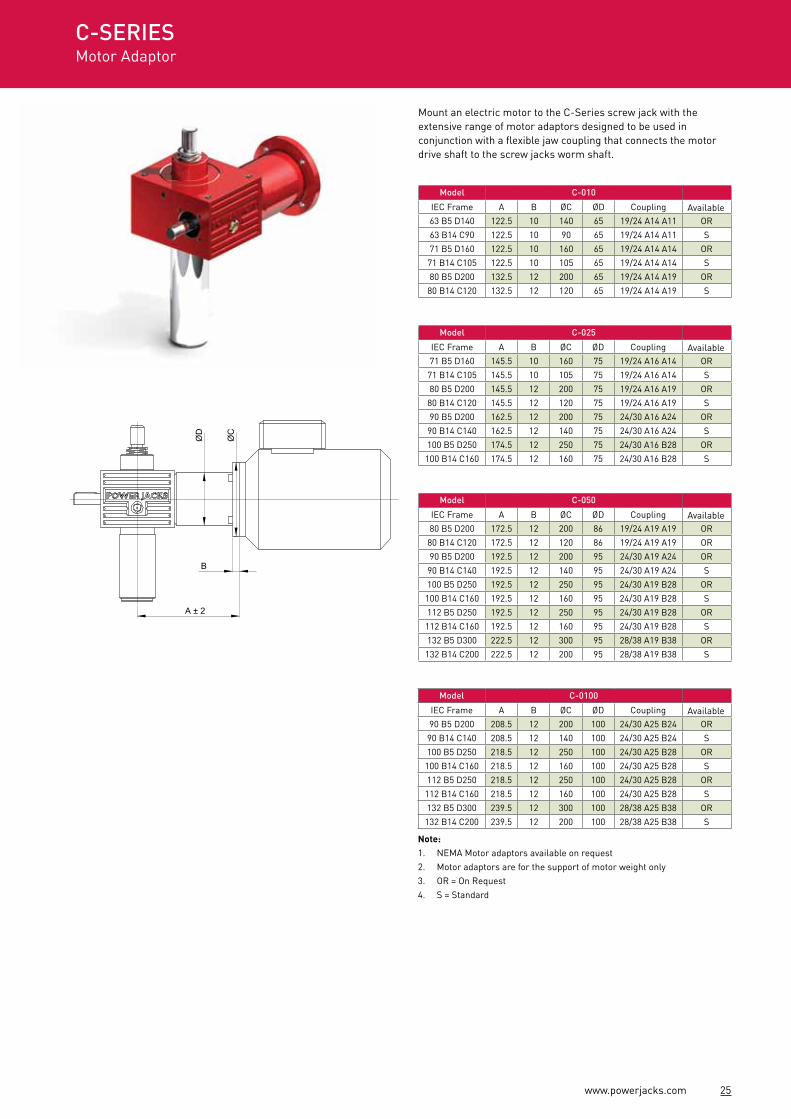
Mount an electric motor to the C-Series screw jack with the extensive range of motor adaptors designed to be used in conjunction with a flexible jaw coupling that connects the motor drive shaft to the screw jacks worm shaft.
Note: 1. NEMA Motor adaptors available on request2. Motor adaptors are for the support of motor weight only3. OR = On Request4. S = Standard
A ± 2
B
ØD
ØC
Model C-010
IEC Frame A B ØC ØD Coupling Available63 B5 D140 122.5 10 140 65 19/24 A14 A11 OR
63 B14 C90 122.5 10 90 65 19/24 A14 A11 S
71 B5 D160 122.5 10 160 65 19/24 A14 A14 OR
71 B14 C105 122.5 10 105 65 19/24 A14 A14 S
80 B5 D200 132.5 12 200 65 19/24 A14 A19 OR
80 B14 C120 132.5 12 120 65 19/24 A14 A19 S
Model C-025
IEC Frame A B ØC ØD Coupling Available71 B5 D160 145.5 10 160 75 19/24 A16 A14 OR
71 B14 C105 145.5 10 105 75 19/24 A16 A14 S
80 B5 D200 145.5 12 200 75 19/24 A16 A19 OR
80 B14 C120 145.5 12 120 75 19/24 A16 A19 S
90 B5 D200 162.5 12 200 75 24/30 A16 A24 OR
90 B14 C140 162.5 12 140 75 24/30 A16 A24 S
100 B5 D250 174.5 12 250 75 24/30 A16 B28 OR
100 B14 C160 174.5 12 160 75 24/30 A16 B28 S
Model C-050
IEC Frame A B ØC ØD Coupling Available80 B5 D200 172.5 12 200 86 19/24 A19 A19 OR
80 B14 C120 172.5 12 120 86 19/24 A19 A19 OR
90 B5 D200 192.5 12 200 95 24/30 A19 A24 OR
90 B14 C140 192.5 12 140 95 24/30 A19 A24 S
100 B5 D250 192.5 12 250 95 24/30 A19 B28 OR
100 B14 C160 192.5 12 160 95 24/30 A19 B28 S
112 B5 D250 192.5 12 250 95 24/30 A19 B28 OR
112 B14 C160 192.5 12 160 95 24/30 A19 B28 S
132 B5 D300 222.5 12 300 95 28/38 A19 B38 OR
132 B14 C200 222.5 12 200 95 28/38 A19 B38 S
Model C-0100
IEC Frame A B ØC ØD Coupling Available90 B5 D200 208.5 12 200 100 24/30 A25 B24 OR
90 B14 C140 208.5 12 140 100 24/30 A25 B24 S
100 B5 D250 218.5 12 250 100 24/30 A25 B28 OR
100 B14 C160 218.5 12 160 100 24/30 A25 B28 S
112 B5 D250 218.5 12 250 100 24/30 A25 B28 OR
112 B14 C160 218.5 12 160 100 24/30 A25 B28 S
132 B5 D300 239.5 12 300 100 28/38 A25 B38 OR
132 B14 C200 239.5 12 200 100 28/38 A25 B38 S
C-SERIESMotor Adaptor
26 www.powerjacks.com
A
D
EØG
BC
FF
FF
SW
ITC
H
STR
OK
E
STR
UC
TUR
E*
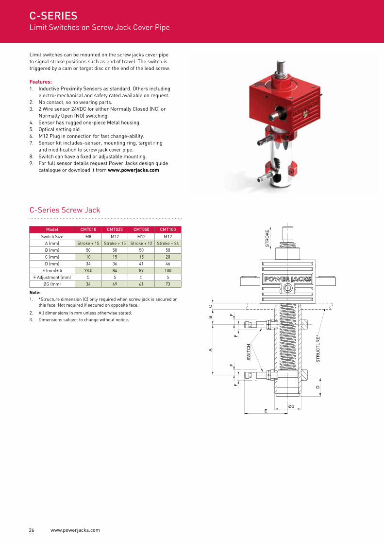
Limit switches can be mounted on the screw jacks cover pipe to signal stroke positions such as end of travel. The switch is triggered by a cam or target disc on the end of the lead screw.
Features:1. Inductive Proximity Sensors as standard. Others including
electro-mechanical and safety rated available on request.2. No contact, so no wearing parts.3. 2 Wire sensor 24VDC for either Normally Closed (NC) or Normally Open (NO) switching.4. Sensor has rugged one-piece Metal housing.5. Optical setting aid 6. M12 Plug in connection for fast change-ability.7. Sensor kit includes–sensor, mounting ring, target ring
and modification to screw jack cover pipe.8. Switch can have a fixed or adjustable mounting.9. For full sensor details request Power Jacks design guide
catalogue or download it from www.powerjacks.com
Note:1. *Structure dimension (C) only required when screw jack is secured on
this face. Not required if secured on opposite face.
2. All dimensions in mm unless otherwise stated.3. Dimensions subject to change without notice.
Model CMT010 CMT025 CMT050 CMT100
Switch Size M8 M12 M12 M12
A (mm) Stroke + 15 Stroke + 15 Stroke + 12 Stroke + 24
B (mm) 50 50 50 50
C (mm) 10 15 15 20
D (mm) 34 36 41 46
E (mm)± 5 78.5 84 89 100
F Adjustment (mm) 5 5 5 5
ØG (mm) 34 49 61 73
C-Series Screw Jack
C-SERIESLimit Switches on Screw Jack Cover Pipe
27www.powerjacks.com
Note:1. All dimension in millimetres unless otherwise stated.2. Designs subject to change without notice.
I
H J
K
AB
ØC
ØD
G
FE
PG16
PLUG
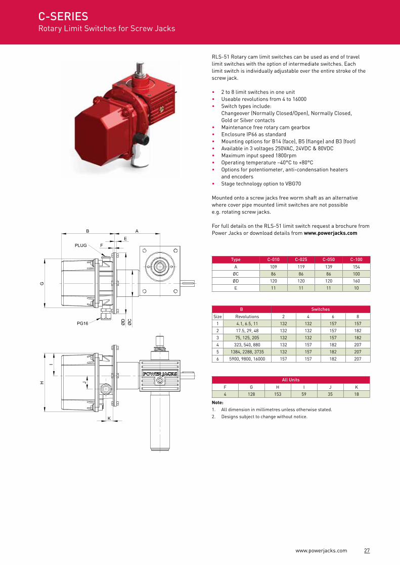
RLS-51 Rotary cam limit switches can be used as end of travel limit switches with the option of intermediate switches. Each limit switch is individually adjustable over the entire stroke of the screw jack.
• 2 to 8 limit switches in one unit• Useable revolutions from 4 to 16000• Switch types include:
Changeover (Normally Closed/Open), Normally Closed, Gold or Silver contacts
• Maintenance free rotary cam gearbox• Enclosure IP66 as standard• Mounting options for B14 (face), B5 (flange) and B3 (foot)• Available in 3 voltages 250VAC, 24VDC & 80VDC• Maximum input speed 1800rpm• Operating temperature –40°C to +80°C• Options for potentiometer, anti-condensation heaters
and encoders• Stage technology option to VBG70
Mounted onto a screw jacks free worm shaft as an alternative where cover pipe mounted limit switches are not possible e.g. rotating screw jacks.
For full details on the RLS-51 limit switch request a brochure from Power Jacks or download details from www.powerjacks.com
Type C-010 C-025 C-050 C-100
A 109 119 139 154
ØC 86 86 86 100
ØD 120 120 120 160
E 11 11 11 10
B Switches
Size Revolutions 2 4 6 8
1 4.1, 6.5, 11 132 132 157 157
2 17.5, 29, 48 132 132 157 182
3 75, 125, 205 132 132 157 182
4 323, 540, 880 132 157 182 207
5 1384, 2288, 3735 132 157 182 207
6 5900, 9800, 16000 157 157 182 207
All Units
F G H I J K
4 128 153 59 35 18
C-SERIESRotary Limit Switches for Screw Jacks
28 www.powerjacks.com
High Performance Reliable Durable Versatile Dynamic
Introducing the high performance S-Series screw jack range from Power Jacks.
To meet the increasing industrial demands on machine screw jacks our team of experienced design engineers set out to provide our customers with a new high performance cubic machine screw jack.
It has typically 50% higher duty cycle capabilities than standard machine screw jacks, thus reducing the need for ball screw jacks or larger de-rated machine screw jacks in high duty applications. In addition the range is engineered to have a long lasting service life, high durability, large selection of configurations, versatile mounting and an extensive accessory list. Ideal for applications that demand more from a machine screw jack, but do not warrant a ball screw jack. Installed singularly or as part of multi-unit jacking systems.
Over 350 Million Standard Configurations per Model Type.
4 Standard Screw Jack Designs• Standard• Anti-Backlash*• Anti-Rotation*• Safety Nut
Anti-Rotation can be combined with standard, anti-backlash and safety nut designs.
* Translating screw configurations.
Gearbox Housing Design optimised for high thermal efficiency. Recognisable by the exterior fins, which increase surface area. The housing is cast using a highly durable SG Iron.
This provides a strong housing that firmly and accurately holds the gear set in a reservoir of chosen lubricant suited to most industrial demands.
Reliable Worm Gear Set Proven gear geometry used in millions of screw jacks.
Oil Filled Gearbox For optimum lubrication and cooling of the worm gear set at up to 3000 rpm input.
Lead Screw Grease Rated for extreme pressure to ensure correct lubrication at all rated loads.
Corrosion Protection To suit all economic needs.• Standard Industrial Paint Finish• Arduous Environment Paint Finish• Customer Specified Paint• Plated Finish
29www.powerjacks.com
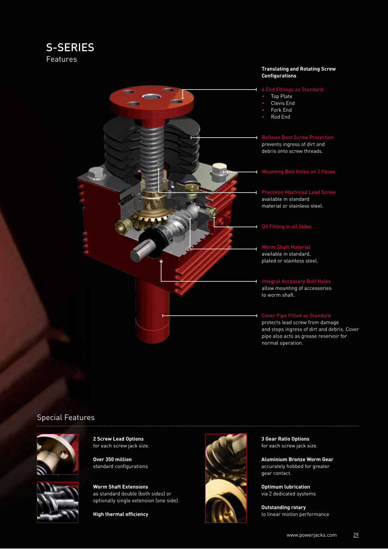
S-SERIESFeatures
Translating and Rotating Screw Configurations
4 End Fittings as Standard:• Top Plate• Clevis End• Fork End• Rod End
Bellows Boot Screw Protectionprevents ingress of dirt and debris onto screw threads.
Mounting Bolt Holes on 2 Faces
Precision Machined Lead Screwavailable in standard material or stainless steel.
Oil Fitting in all Sides
Worm Shaft Materialavailable in standard, plated or stainless steel.
Integral Accessory Bolt Holesallow mounting of accessories to worm shaft.
Cover Pipe Fitted as Standardprotects lead screw from damage and stops ingress of dirt and debris. Cover pipe also acts as grease reservoir for normal operation.
Special Features
2 Screw Lead Options for each screw jack size.
Over 350 million standard configurations
3 Gear Ratio Options for each screw jack size.
Aluminium Bronze Worm Gear accurately hobbed for greater gear contact.
Optimum lubricationvia 2 dedicated systems
Outstanding rotary to linear motion performance
Worm Shaft Extensions as standard double (both sides) or optionally single extension (one side).
High thermal efficiency
30 www.powerjacks.com
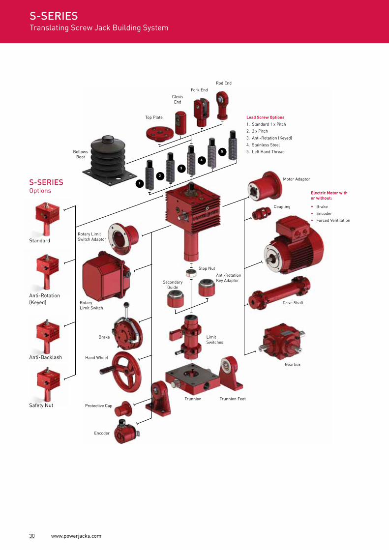
S-SERIESTranslating Screw Jack Building System
Lead Screw Options
1. Standard 1 x Pitch
2. 2 x Pitch
3. Anti-Rotation (Keyed)
4. Stainless Steel
5. Left Hand Thread
Electric Motor with or without:
• Brake
• Encoder
• Forced Ventilation
Motor Adaptor
Coupling
Drive Shaft
Gearbox
Stop Nut
Trunnion Feet
Limit Switches
Secondary Guide
Anti-Rotation Key Adaptor
Rotary Limit Switch Adaptor
Bellows Boot
Top Plate
Clevis End
Fork End
Rod End
Rotary Limit Switch
Trunnion
Brake
Hand Wheel
Protective Cap
Encoder
S-SERIESOptions
Standard
Anti-Rotation (Keyed)
Anti-Backlash
Safety Nut
2
1
3
4
5
31www.powerjacks.com
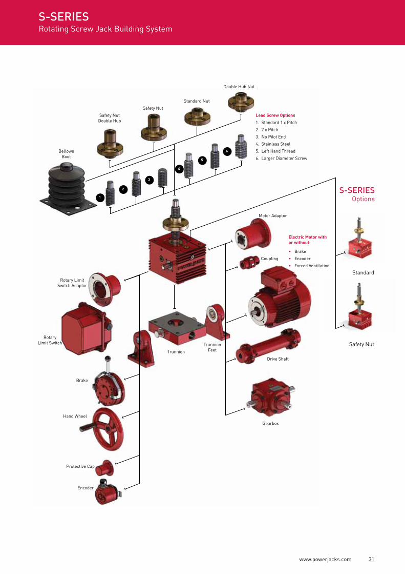
S-SERIESRotating Screw Jack Building System
Motor Adaptor
Coupling
Drive Shaft
Gearbox
Trunnion Feet
Rotary Limit Switch Adaptor
Bellows Boot
Safety Nut Double Hub
Safety Nut
Standard Nut
Double Hub Nut
Rotary Limit Switch
Trunnion
Brake
Hand Wheel
Protective Cap
Encoder
Standard
Safety Nut
S-SERIESOptions
Lead Screw Options
1. Standard 1 x Pitch
2. 2 x Pitch
3. No Pilot End
4. Stainless Steel
5. Left Hand Thread
6. Larger Diameter Screw
Electric Motor with or without:
• Brake
• Encoder
• Forced Ventilation
2
1
3
4
5
6

32 www.powerjacks.com
Example
1 2 3 4 5 6 6 7 8 9 10 11 12 13 14 15 16 17 18 19 20 21 22 23 24 25
S T O 2 5 1 5 0 0 C 1 R K C P C 1 B 3 B 0 0 0 B 0
S-SERIESScrew Jack Product Code
Example
Notes:#1. Rotating screw models only.#2. Standard right hand thread form. Worm shaft turns clockwise to extend screw.#3. Left hand thread form. Worm shaft turns anti-clockwise to extend screw.#4. Factory designated number for special design.#5. Grease filled gearbox recommended for normal running input speed below 500rpm.#6. Includes motor adaptor and coupling. IEC motor adaptor is standard.#7. Trunnions on same side as worm shaft (standard).#8. Trunnions at 90° to worm shaft.#9. Limit switch mounting included.#10. Design notes required to detail device/item specification.#11. Plain end “A” has same dimensions as “E – threaded end” except no thread form.
1 Screw Jack TypeS = S-Series Screw Jack
2 Screw ConfigurationT = Translating ScrewR = Rotating Screw
3,4,5 Capacity (kN)025 = 25kN050 = 50kN100 = 100kN200 = 200kN
6,7,8,9 Stroke (mm)e.g.1500 = 1500mm
10 End TypeE = Threaded EndC = ClevisT = Top PlateF = Fork EndR = Rod EndA = Plain End#11
P = Pilot End#1
N = No Pilot#1
11 Lead Screw Pitch1 = Option 1 Lead2 = Option 2 Lead
12 Gear Ratio1 = Option 1 Ratio2 = Option 2 Ratio3 = Option 3 RatioX = Special Ratio
13 Features0 = NoneK = Anti-Rotation (keyed)C = Secondary GuideR = Anti-BacklashV = Inverted Screw Anti-BacklashY = Anti-Backlash & Anti-Rotation (keyed)W = Inverted Screw Anti-Backlash & Anti-Rotation (keyed)H = Double Hub Nut#1
14 DesignationF = Factory Designated#4
C = Oil Filled GearboxA = Grease Filled Gearbox#5
15 Cover PipeP = Cover PipeF = No Cover Pipe
16 Lead Screw ThreadC = Right Hand (Clockwise)#2
A = Left Hand (Anti-Clockwise)#3
17 Lead Screw Material1 = Carbon Steel (Standard)2 = Stainless SteelL = Large Diameter#1 #10
T = Large Diameter Stainless Steel#1 #10
18 Lead Screw Cover0 = NoneB = Bellows Boot (fabric)T = Telescopic Spiral (metal)
19 Drive0 = No Side Bolt Holes1 = Side Bolt Holes – LHS2 = Side Bolt Holes – RHS3 = Side Bolt Holes (both sides)M = Motor#6, #10
B = Brake Motor#6, #10
H = Hand WheelA = Motor Adaptor#6, #10
20 Worm Shaft Ends0 = BothL = Left Hand Side OnlyR = Right Hand Side Only
21 Worm Shaft Type0 = Standard MaterialN = Nickel PlatedC = Chrome PlatedS = Stainless Steel
22 Stop Nut0 = No Stop NutP = Full Power Stop Nut
23 Safety Nut0 = No Safety NutT = Safety Nut TensionC = Safety Nut Compression
24 Gearbox MountingB = Base MountT = Trunnion Mount Standard#7
U = T + Trunnion FeetX = Trunnion Mount 90°#8
Y = X + Trunnion Feet
25 Limit Switch #9, #10
0 = NoneL = Electro-Mechanical Limit SwitchR = Rotary Cam Limit SwitchP = Proximity Sensor
33www.powerjacks.com
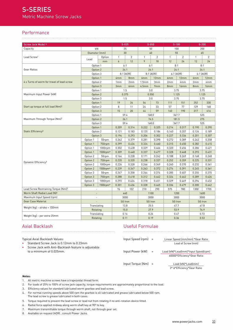
Performance
Notes:1. All metric machine screws have a trapezoidal thread form.2. For loads of 25% to 100% of screw jack capacity, torque requirements are approximately proportional to the load.3. Efficiency values for standard lubricated worm gearbox and lead screw.4. For normal running speeds above 500 rpm the gearbox is oil lubricated and grease lubricated below 500 rpm.
The lead screw is grease lubricated in both cases.
5. Torque required to prevent the lead screw or lead nut from rotating if no anti-rotation device fitted.6. Radial force applied midway along worm shaft key at 90º to key.7. Maximum transmittable torque through worm shaft, not through gear set.8. Available on request (AOR) , consult Power Jacks.
Axial Backlash
Typical Axial Backlash Values:• Standard Screw Jack is 0.12mm to 0.23mm• Screw Jack with Anti-Backlash feature is adjustable
to a minimum of 0.025mm.
Screw Jack Model 4 S-025 S-050 S-100 S-200
Capacity kN 25 50 100 200
Lead Screw1
Diameter (mm) 30 40 55 65
LeadOption 1 2 1 2 1 2 1 2
mm 6 12 9 18 12 24 12 24
Gear RatiosOption 1 6:1 6:1 8:1 8:1
Option 2 24:1 24:1 24:1 24:1
Option 3 8:1 (AOR) 8:1 (AOR) 6:1 (AOR) 6:1 (AOR)
4 x Turns of worm for travel of lead screwOption 1 4mm 8mm 6mm 12mm 6mm 12mm 6mm 12mm
Option 2 1mm 2mm 1.5mm 3mm 2mm 4mm 2mm 4mm
Option 3 3mm 6mm 4.5mm 9mm 8mm 16mm 8mm 16mm
Maximum Input Power (kW)Option 1 1.5 3.0 3.75 3.75
Option 2 0.375 0.550 1.125 1.125
Option 3 1.5 3.0 3.75 3.75
Start up torque at full load (Nm)2
Option 1 19 26 54 73 111 151 252 330
Option 2 8 11 24 33 57 77 129 168
Option 3 15 20 44 59 140 190 317 416
Maximum Through Torque (Nm)7
Option 1 59.4 168.0 347.7 525
Option 2 26.1 76.5 181.5 275
Option 3 59.4 168.0 347.7 525
Static Efficiency3
Option 1 0.209 0.314 0.222 0.325 0.214 0.317 0.190 0.290
Option 2 0.121 0.183 0.125 0.184 0.140 0.207 0.124 0.189
Option 3 0.194 0.293 0.206 0.302 0.227 0.336 0.201 0.307
Dynamic Efficiency3
Option 1 50rpm 0.262 0.379 0.281 0.398 0.272 0.389 0.243 0.358
Option 1 750rpm 0.299 0.434 0.324 0.460 0.315 0.450 0.282 0.415
Option 1 1000rpm 0.302 0.438 0.329 0.466 0.320 0.456 0.286 0.421
Option 1 1500rpm+ 0.309 0.448 0.337 0.477 0.328 0.468 0.293 0.431
Option 2 50rpm 0.164 0.238 0.171 0.242 0.188 0.269 0.168 0.248
Option 2 750rpm 0.220 0.320 0.238 0.337 0.252 0.359 0.225 0.331
Option 2 1000rpm 0.226 0.328 0.246 0.349 0.260 0.370 0.232 0.341
Option 2 1500rpm+ 0.239 0.347 0.263 0.372 0.274 0.391 0.245 0.361
Option 3 50rpm 0.247 0.358 0.264 0.374 0.285 0.407 0.255 0.375
Option 3 750rpm 0.288 0.418 0.312 0.442 0.324 0.462 0.289 0.426
Option 3 1000rpm 0.293 0.424 0.318 0.451 0.329 0.469 0.294 0.432
Option 3 1500rpm+ 0.301 0.436 0.328 0.465 0.336 0.479 0.300 0.442Lead Screw Restraining Torque (Nm)5 - 76 102 210 290 575 780 1300 1705Worm Shaft Radial Load (N)6 - 440 1100 1200 1600Maximum Input Speed (rpm) - 3000 3000 3000 3000Gear Case Material - SG Iron SG Iron SG Iron SG Iron
Weight (kg) – stroke = 150mmTranslating 13.8 25.5 47.7 67.8
Rotating 15.0 27.9 53.9 76.9
Weight (kg) – per extra 25mmTranslating 0.16 0.24 0.47 0.72
Rotating 0.11 0.19 0.36 0.53
S-SERIESMetric Machine Screw Jacks
Load (kN)*Lead(mm)*Input Speed(rpm) 60000*Efficiency*Gear Ratio
Input Speed (rpm) =
Input Power (kW) =
Input Torque (Nm) =
Linear Speed (mm/min) *Gear Ratio Lead of Screw (mm)
Useful Formulae
Load (kN)*Lead(mm) 2* π*Efficiency*Gear Ratio
34 www.powerjacks.comS
TRO
KE
+ 6
025
20
40
90
15 40
STR
OK
E
50
15
30
40
20
(BE
LLO
WS
BO
OT
NO
T IN
CLU
DE
D)
HUB FORBELLOWS
BOOT
65
4 x Ø13.5
LHS
RHS(S
N)
STR
OK
E
57.5
115
30
157
52
30
46
4 M
AX
STR
OK
E
M20 x 2.5
(CLO
SE
D H
EIG
HT)
M6 x 114 DEEP
3030
9595
190
Ø16 (h8)
130
65
100
50
160
7043.3143.26
120
5 x 5 x 25M12 x 1.75
16 DEEP(BOTH SIDES)
LHS
RHS
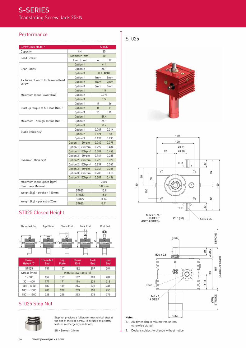
Performance
ST025 Closed Height
ST025
ClosedHeight ‘C'
ThreadedEnd
Top Plate
ClevisEnd
ForkEnd
RodEnd
ST025 157 157 182 207 204
Stroke (mm) With Bellow Boots (B)
0 - 300 157 157 182 207 204
301 - 600 171 171 196 221 218
601 - 1050 189 189 214 239 236
1051 - 1500 208 208 233 258 255
1501 - 1800 228 228 253 278 275
Screw Jack Model 4 S-025
Capacity kN 25
Lead Screw1Diameter (mm) 30
Lead (mm) 6 12
Gear Ratios
Option 1 6:1
Option 2 24:1
Option 3 8:1 (AOR)
4 x Turns of worm for travel of lead screw
Option 1 4mm 8mm
Option 2 1mm 2mm
Option 3 3mm 6mm
Maximum Input Power (kW)
Option 1 1.5
Option 2 0.375
Option 3 1.5
Start up torque at full load (Nm)2
Option 1 19 26
Option 2 8 11
Option 3 15 20
Maximum Through Torque (Nm)7
Option 1 59.4
Option 2 26.1
Option 3 59.4
Static Efficiency3Option 1 0.209 0.314
Option 2 0.121 0.183
Option 3 0.194 0.293
Dynamic Efficiency3
Option 1 50rpm 0.262 0.379
Option 1 750rpm 0.299 0.434
Option 1 1500rpm+ 0.309 0.448
Option 2 50rpm 0.164 0.238
Option 2 750rpm 0.220 0.320
Option 2 1500rpm+ 0.239 0.347
Option 3 50rpm 0.247 0.358
Option 3 750rpm 0.288 0.418
Option 3 1500rpm+ 0.301 0.436
Maximum Input Speed (rpm) - 3000
Gear Case Material - SG Iron
Weight (kg) – stroke = 150mmST025 13.8
SR025 15.0
Weight (kg) – per extra 25mmSR025 0.16
ST025 0.11
S-SERIESTranslating Screw Jack 25kN
ST025 Stop Nut
Stop nut provides a full power mechanical stop at the end of the lead screw. To be used as a safety feature in emergency conditions.
SN = Stroke + 21mm
Threaded End Top Plate Clevis End Fork End Rod End
Note:1. All dimension in millimetres unless
otherwise stated.
2. Designs subject to change without notice.
C C C C C
35www.powerjacks.com
Accessories & Options
Rotary Limit Switch Adaptor
Anti-BacklashEnd Fittings
Anti-Rotation (Keyed)
Limit Switches
Double Hub Nut
DrivesSafety Nut
Motor Adaptors
Secondary Guide
Trunnion Mounts
Corrosion Protection
A
GE
D
F
CCDA
GE
B
F
SR025
ØA B ØC D E ØF
ST025 40 2 130 10 10 45
SR025 40 2 130 10 15 40
Stroke 1 – 300 301 – 600 601 – 1050 1051 – 1500 1501 – 1800
G 14 28 46 65 85*
S-SERIESRotating Screw Jack 25kN
200 400 600 800 1000 1200 1400100 200 300 400 500 600 700
FIXED/GUIDEDPINNED/PINNED
FIXED/FREE
00 200 400 600 800 1000 1200 1400 1600 1800 2000
3000
PER
MIS
SIBL
E C
OM
PRES
SIVE
LO
AD (K
G)
2500
2000
1500
1000
500
1600
COLUMN LENGTH (mm)
Column Strength
Cri
tical
Spe
ed (r
pm)
1
100
1000
1010
Critical Screw Speed
Bellows Boot
L
L
L
Fixed/Free, Fcs = 0.15
Fixed/Supported, Fcs = 0.7
Fixed/Fixed, Fcs = 1
L L L
Unsupported Screw Length (m)(Based on both ends fixed and 80% of the critical speed)
*control tapes fitted ØC=150
Gearbox Nut
Free Pinned Guided
Fixed Pinned Fixed
STR
OK
E +
60
25
20
40
90
15 40
STR
OK
E
50
15
30
40
20
(BE
LLO
WS
BO
OT
NO
T IN
CLU
DE
D)
HUB FORBELLOWS
BOOT
65
4 x Ø13.5
LHS
RHS
(SN
)S
TRO
KE
57.5
115
30
157
52
30
46
4 M
AX
STR
OK
E
M20 x 2.5
(CLO
SE
D H
EIG
HT)
M6 x 114 DEEP
3030
9595
190
Ø16 (h8)
130
65
100
50
160
7043.3143.26
120
5 x 5 x 25M12 x 1.75
16 DEEP(BOTH SIDES)
LHS
RHS


![Le Châtelier’s principle. The significance of Kc values Kc = Products Reactants Kc = Products Reactants If Kc is small (0.001 or lower), [products] must](https://img.pdfslide.us/doc/110x75/56649cff5503460f949cff35/le-chateliers-principle-the-significance-of-kc-values-kc-products-reactants.jpg)