Embed Size (px)
Citation preview

Carlon® Master CatalogBoreable Multi-Gard® Trenchless
Raceway
Bore-Gard® Trenchless Raceway
Carflex® Liquidtight Fittings
Carflex® Liquidtight FlexibleNonmetallic Tubing
Carflex® Omni Connectors
Carflex® Pre-Wired Liquidtight Whips
Carflex® X-Flex™ Flexible Nonmetallic Tubing
Cement
Chimes
Circuit Safe® JIC Enclosures
Circuit Safe® NEMA Enclosures
Cord Grips
Curved Lid J-Box
ENT Boxes and Fittings
Flex-Plus® Blue™ ENT
Floor Box Systems
Hal-Free Riser-Gard®
High Density Polyethylene (HDPE)
Himeline® Enclosures
Intra-Gard® Multi-Cell Raceway
In-Use Weatherproof Covers
Junction Boxes
Multi-Gard® Multi-Cell Raceway
P&C Duct® - Types EB and DB
P&C Duct® Fittings and Sweeps
P&C Flex® Corrugated Flexible Conduit
Plenum-Gard® Flexible Raceway
PV-Mold Pole Riser System
Riser-Gard® Flexible Raceway
Schedule 40 & 80 Conduit
Schedule 40 & 80 Fittings
Schedule 40 & 80 Special/Standard Elbows
Slack and Splice Enclosures
Slip Meter Risers
Snap-Loc® Spacers
Split Duct
Structured Cable Management Systems
Telephone Duct – Types B, C and D
Telephone Duct Fittings and Sweeps
Utility Conduit, Fittings, and Elbows
Weatherproof Covers and Lighting Systems
Wire-Safe® Wireway and Wiring Trough
Zip Box® Blue™ Switch/Outlet Boxes
w w w . c a r l o n . c o m 1
Electrical Products
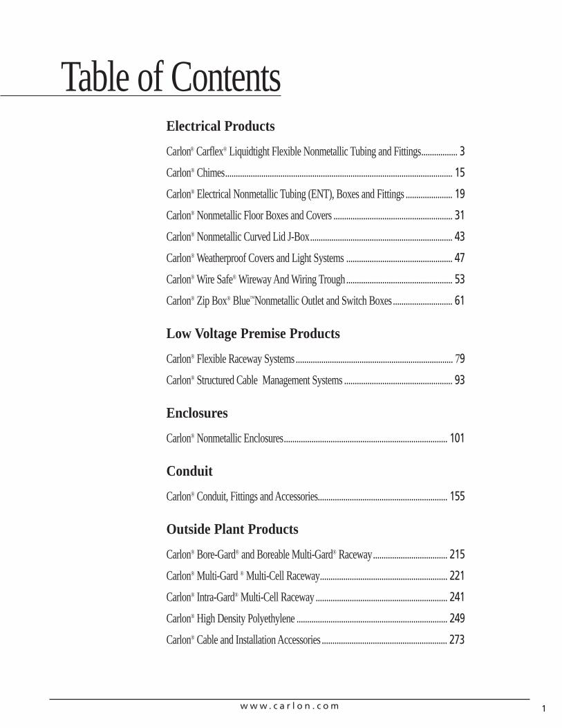
Carlon® Carflex® Liquidtight Flexible Nonmetallic Tubing and Fittings................. 3
Carlon® Chimes........................................................................................................... 15
Carlon® Electrical Nonmetallic Tubing (ENT), Boxes and Fittings ...................... 19
Carlon® Nonmetallic Floor Boxes and Covers ........................................................ 31
Carlon® Nonmetallic Curved Lid J-Box................................................................... 43
Carlon® Weatherproof Covers and Light Systems .................................................. 47
Carlon® Wire Safe® Wireway And Wiring Trough.................................................. 53
Carlon® Zip Box® Blue™Nonmetallic Outlet and Switch Boxes............................ 61
Low Voltage Premise Products
Carlon® Flexible Raceway Systems.......................................................................... 79
Carlon® Structured Cable Management Systems ................................................... 93
Enclosures
Carlon® Nonmetallic Enclosures............................................................................. 101
Conduit
Carlon® Conduit, Fittings and Accessories............................................................. 155
Outside Plant Products
Carlon® Bore-Gard® and Boreable Multi-Gard® Raceway................................... 215
Carlon® Multi-Gard ® Multi-Cell Raceway............................................................ 221
Carlon® Intra-Gard® Multi-Cell Raceway .............................................................. 241
Carlon® High Density Polyethylene ....................................................................... 249
Carlon® Cable and Installation Accessories ........................................................... 273
Table of Contents

w w w . c a r l o n . c o m2
w w w . c a r l o n . c o m 3
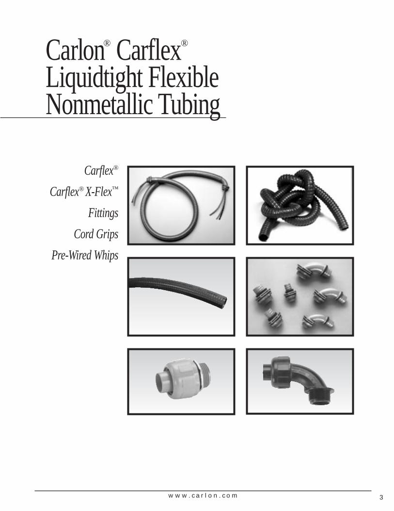
Carlon® Carflex®
Liquidtight Flexible Nonmetallic Tubing
Carflex®
Carflex® X-Flex™
Fittings
Cord Grips
Pre-Wired Whips
w w w . c a r l o n . c o m4
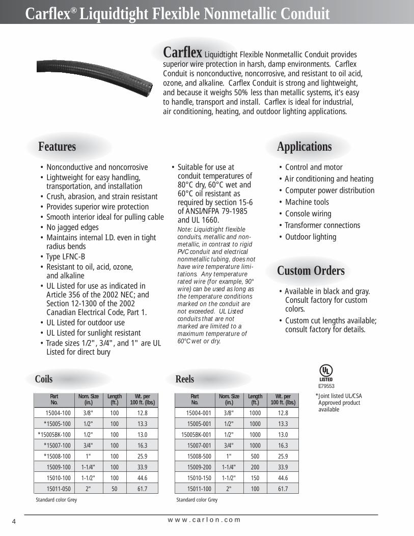
Carflex® Liquidtight Flexible Nonmetallic Conduit
Carflex Liquidtight Flexible Nonmetallic Conduit providessuperior wire protection in harsh, damp environments. CarflexConduit is nonconductive, noncorrosive, and resistant to oil acid,ozone, and alkaline. Carflex Conduit is strong and lightweight,and because it weighs 50% less than metallic systems, it’s easyto handle, transport and install. Carflex is ideal for industrial,air conditioning, heating, and outdoor lighting applications.
Features
Coils
Part Nom. Size Length Wt. perNo. (in.) (ft.) 100 ft. (lbs.)
15004-100 3/8" 100 12.8
*15005-100 1/2" 100 13.3
*15005BK-100 1/2" 100 13.0
*15007-100 3/4" 100 16.3
*15008-100 1" 100 25.9
15009-100 1-1/4" 100 33.9
15010-100 1-1/2" 100 44.6
15011-050 2" 50 61.7
Standard color Grey
Reels
Part Nom. Size Length Wt. perNo. (in.) (ft.) 100 ft. (lbs.)
15004-001 3/8" 1000 12.8
15005-001 1/2" 1000 13.3
15005BK-001 1/2" 1000 13.0
15007-001 3/4" 1000 16.3
15008-500 1" 500 25.9
15009-200 1-1/4" 200 33.9
15010-150 1-1/2" 150 44.6
15011-100 2" 100 61.7
Standard color Grey
Applications• Control and motor• Air conditioning and heating • Computer power distribution• Machine tools• Console wiring• Transformer connections• Outdoor lighting
Custom Orders• Available in black and gray.
Consult factory for customcolors.
• Custom cut lengths available;consult factory for details.
• Nonconductive and noncorrosive• Lightweight for easy handling,
transportation, and installation• Crush, abrasion, and strain resistant• Provides superior wire protection• Smooth interior ideal for pulling cable• No jagged edges• Maintains internal I.D. even in tight
radius bends• Type LFNC-B• Resistant to oil, acid, ozone,
and alkaline• UL Listed for use as indicated in
Article 356 of the 2002 NEC; andSection 12-1300 of the 2002Canadian Electrical Code, Part 1.
• UL Listed for outdoor use• UL Listed for sunlight resistant• Trade sizes 1/2", 3/4", and 1" are UL
Listed for direct bury
• Suitable for use at conduit temperatures of80°C dry, 60°C wet and60°C oil resistant asrequired by section 15-6of ANSI/NFPA 79-1985and UL 1660.Note: Liquidtight flexibleconduits, metallic and non-metallic, in contrast to rigidPVC conduit and electricalnonmetallic tubing, does nothave wire temperature limi-tations. Any temperaturerated wire (for example, 90°wire) can be used as long asthe temperature conditionsmarked on the conduit arenot exceeded. UL Listedconduits that are notmarked are limited to amaximum temperature of60°C wet or dry.
*Joint listed UL/CSAApproved productavailable
E79553
w w w . c a r l o n . c o m 5
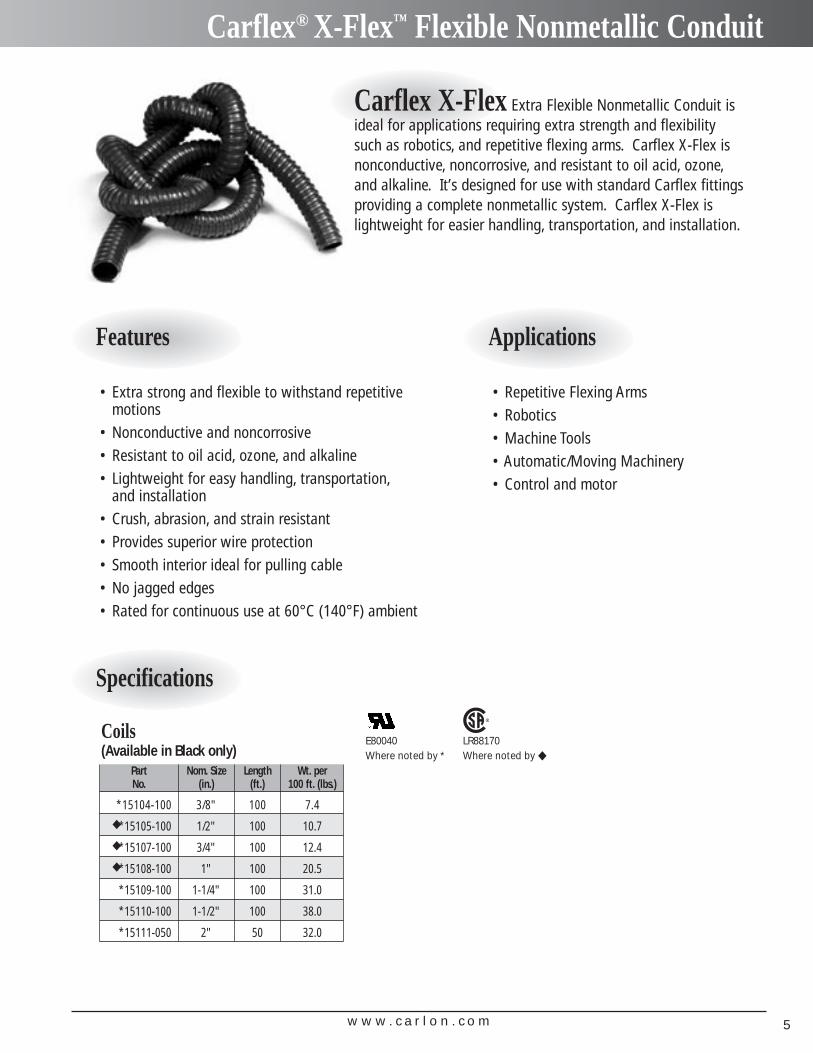
Carflex® X-Flex™ Flexible Nonmetallic Conduit
Specifications
Coils(Available in Black only)
Part Nom. Size Length Wt. perNo. (in.) (ft.) 100 ft. (lbs.)
*15104-100 3/8" 100 7.4◆ *15105-100 1/2" 100 10.7◆ *15107-100 3/4" 100 12.4◆ *15108-100 1" 100 20.5
*15109-100 1-1/4" 100 31.0
*15110-100 1-1/2" 100 38.0
*15111-050 2" 50 32.0
Carflex X-Flex Extra Flexible Nonmetallic Conduit isideal for applications requiring extra strength and flexibilitysuch as robotics, and repetitive flexing arms. Carflex X-Flex isnonconductive, noncorrosive, and resistant to oil acid, ozone,and alkaline. It’s designed for use with standard Carflex fittingsproviding a complete nonmetallic system. Carflex X-Flex islightweight for easier handling, transportation, and installation.
Features Applications
• Extra strong and flexible to withstand repetitivemotions
• Nonconductive and noncorrosive• Resistant to oil acid, ozone, and alkaline• Lightweight for easy handling, transportation,
and installation• Crush, abrasion, and strain resistant• Provides superior wire protection• Smooth interior ideal for pulling cable• No jagged edges• Rated for continuous use at 60°C (140°F) ambient
• Repetitive Flexing Arms• Robotics• Machine Tools• Automatic/Moving Machinery• Control and motor
LR88170Where noted by ◆
E80040Where noted by *
w w w . c a r l o n . c o m6
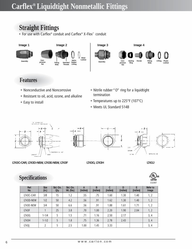
Carflex® Liquidtight Nonmetallic Fittings
Straight Fittings• For use with Carflex® conduit and Carflex® X-Flex™ conduit
Features
• Nonconductive and Noncorrosive
• Resistant to oil, acid, ozone, and alkaline
• Easy to install
• Nitrile rubber “O” ring for a liquidtight termination
• Temperatures up to 225°F (107°C)
• Meets UL Standard 514B
SpecificationsPart Size Std. Ctn. Std. Ctn. A B C D E Refer toNo. (in.) Qty. Wt. (lbs.) (inches) (inches) (inches) (inches) (inches) Image
LT43C-CAR 3/8 15 1.2 .55 .75 1.60 1.30 1.40 1, 2
LT43D-NEW 1/2 50 4.2 .56 .91 1.62 1.30 1.40 1, 2
LT43E-NEW 3/4 50 6.6 .56 .91 1.88 1.61 1.71 1, 2
LT43F 1 25 3.8 .70 1.00 2.20 1.90 2.04 1, 2
LT43G 1-1/4 5 1.5 .71 1.16 2.50 2.17 3, 4
LT43H 1-1/2 5 1.8 .75 1.36 2.78 2.43 3, 4
LT43J 2 5 2.5 1.00 1.45 3.33 3, 4
Com-pression
Nut
SealingRing
Ferrule FittingBody
O Ring PlasticLocknutFitting
BodyExtendedThreads
Com-pression
Nut
NitrileRubberO-Ring
MetalLocknut
Image 1 Image 2 Image 3 Image 4
E32447
LT43C-CAR, LT43D-NEW, LT43E-NEW, LT43F LT43G, LT43H LT43J
AssemblyAssembly
w w w . c a r l o n . c o m 7
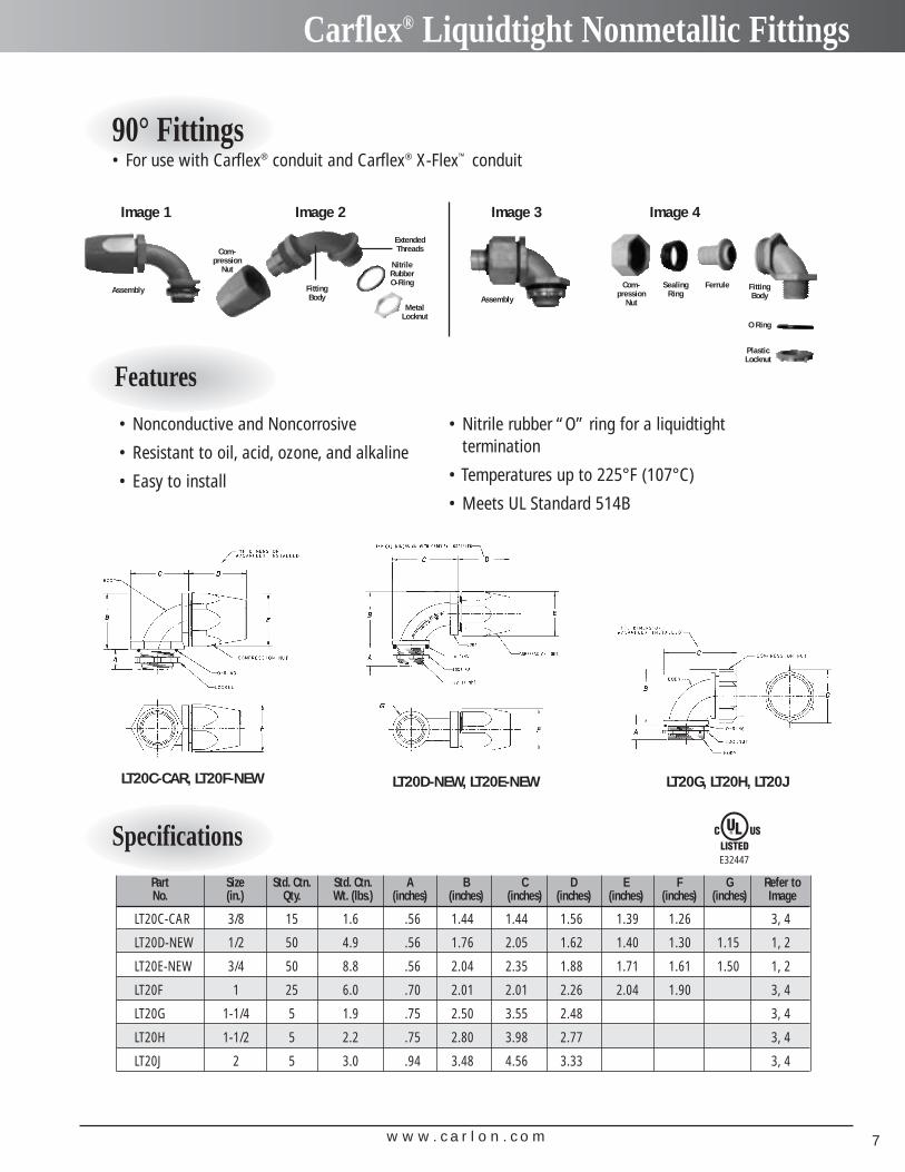
Carflex® Liquidtight Nonmetallic Fittings
90° Fittings• For use with Carflex® conduit and Carflex® X-Flex™ conduit
Features
• Nonconductive and Noncorrosive
• Resistant to oil, acid, ozone, and alkaline
• Easy to install
• Nitrile rubber “O” ring for a liquidtight termination
• Temperatures up to 225°F (107°C)
• Meets UL Standard 514B
SpecificationsPart Size Std. Ctn. Std. Ctn. A B C D E F G Refer toNo. (in.) Qty. Wt. (lbs.) (inches) (inches) (inches) (inches) (inches) (inches) (inches) Image
LT20C-CAR 3/8 15 1.6 .56 1.44 1.44 1.56 1.39 1.26 3, 4
LT20D-NEW 1/2 50 4.9 .56 1.76 2.05 1.62 1.40 1.30 1.15 1, 2
LT20E-NEW 3/4 50 8.8 .56 2.04 2.35 1.88 1.71 1.61 1.50 1, 2
LT20F 1 25 6.0 .70 2.01 2.01 2.26 2.04 1.90 3, 4
LT20G 1-1/4 5 1.9 .75 2.50 3.55 2.48 3, 4
LT20H 1-1/2 5 2.2 .75 2.80 3.98 2.77 3, 4
LT20J 2 5 3.0 .94 3.48 4.56 3.33 3, 4
Com-pression
Nut
SealingRing
Ferrule FittingBody
O Ring
PlasticLocknut
ExtendedThreads
NitrileRubberO-Ring
MetalLocknut
FittingBody
Com-pression
Nut
Image 1 Image 2 Image 3 Image 4
E32447
LT20C-CAR, LT20F-NEW LT20D-NEW, LT20E-NEW LT20G, LT20H, LT20J
AssemblyAssembly
w w w . c a r l o n . c o m8
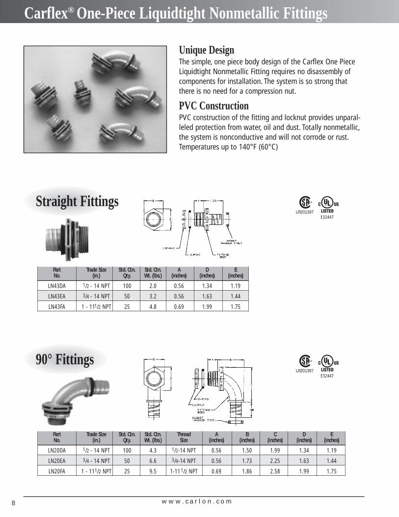
Carflex® One-Piece Liquidtight Nonmetallic Fittings
Straight Fittings
Part Trade Size Std. Ctn. Std. Ctn. A D ENo. (in.) Qty. Wt. (lbs.) (inches) (inches) (inches)
LN43DA 1/2 - 14 NPT 100 2.0 0.56 1.34 1.19
LN43EA 3/4 - 14 NPT 50 3.2 0.56 1.63 1.44
LN43FA 1 - 111/2 NPT 25 4.8 0.69 1.99 1.75
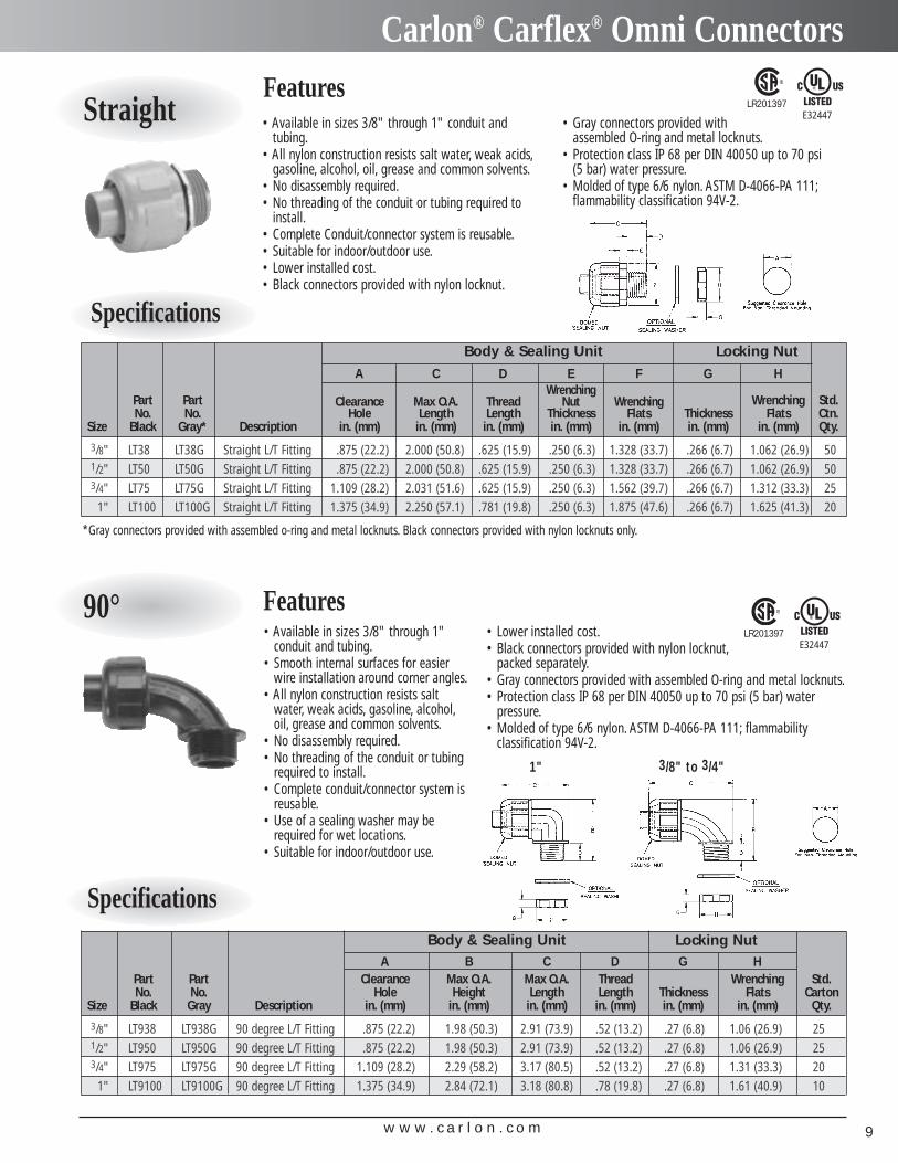
90° Fittings
Part Trade Size Std. Ctn. Std. Ctn. Thread A B C D ENo. (in.) Qty. Wt. (lbs.) Size (inches) (inches) (inches) (inches) (inches)
LN20DA 1/2 - 14 NPT 100 4.3 1/2-14 NPT 0.56 1.50 1.99 1.34 1.19
LN20EA 3/4 - 14 NPT 50 6.6 3/4-14 NPT 0.56 1.73 2.25 1.63 1.44
LN20FA 1 - 111/2 NPT 25 9.5 1-11 1/2 NPT 0.69 1.86 2.58 1.99 1.75
Unique DesignThe simple, one piece body design of the Carflex One PieceLiquidtight Nonmetallic Fitting requires no disassembly ofcomponents for installation. The system is so strong thatthere is no need for a compression nut.
PVC ConstructionPVC construction of the fitting and locknut provides unparal-leled protection from water, oil and dust. Totally nonmetallic,the system is nonconductive and will not corrode or rust.Temperatures up to 140°F (60°C)
E32447LR201397
E32447LR201397
w w w . c a r l o n . c o m 9
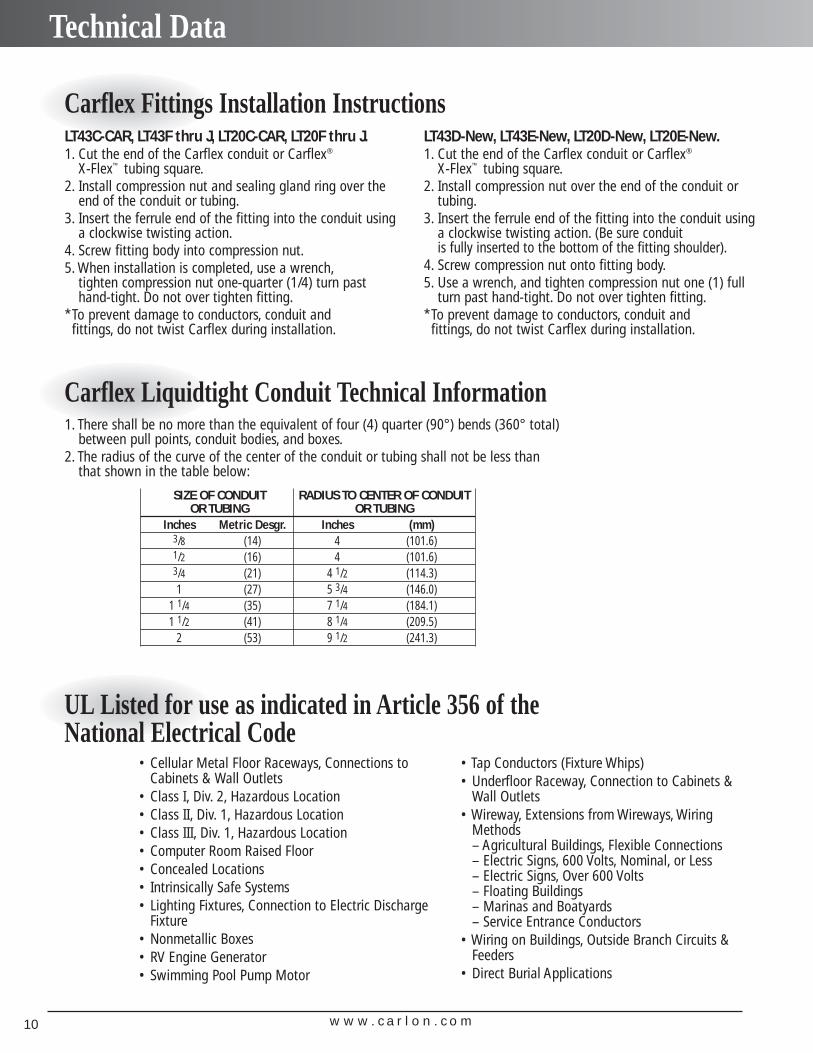
Carlon® Carflex® Omni Connectors
1" 3/8" to 3/4"
A C D E F G HWrenching
Part Part Clearance Max O.A. Thread Nut Wrenching Wrenching Std.No. No. Hole Length Length Thickness Flats Thickness Flats Ctn.
Size Black Gray* Description in. (mm) in. (mm) in. (mm) in. (mm) in. (mm) in. (mm) in. (mm) Qty.
3/8" LT38 LT38G Straight L/T Fitting .875 (22.2) 2.000 (50.8) .625 (15.9) .250 (6.3) 1.328 (33.7) .266 (6.7) 1.062 (26.9) 501/2" LT50 LT50G Straight L/T Fitting .875 (22.2) 2.000 (50.8) .625 (15.9) .250 (6.3) 1.328 (33.7) .266 (6.7) 1.062 (26.9) 503/4" LT75 LT75G Straight L/T Fitting 1.109 (28.2) 2.031 (51.6) .625 (15.9) .250 (6.3) 1.562 (39.7) .266 (6.7) 1.312 (33.3) 25
1" LT100 LT100G Straight L/T Fitting 1.375 (34.9) 2.250 (57.1) .781 (19.8) .250 (6.3) 1.875 (47.6) .266 (6.7) 1.625 (41.3) 20
Body & Sealing Unit Locking Nut
A B C D G HPart Part Clearance Max O.A. Max O.A. Thread Wrenching Std.No. No. Hole Height Length Length Thickness Flats Carton
Size Black Gray Description in. (mm) in. (mm) in. (mm) in. (mm) in. (mm) in. (mm) Qty.
3/8" LT938 LT938G 90 degree L/T Fitting .875 (22.2) 1.98 (50.3) 2.91 (73.9) .52 (13.2) .27 (6.8) 1.06 (26.9) 251/2" LT950 LT950G 90 degree L/T Fitting .875 (22.2) 1.98 (50.3) 2.91 (73.9) .52 (13.2) .27 (6.8) 1.06 (26.9) 253/4" LT975 LT975G 90 degree L/T Fitting 1.109 (28.2) 2.29 (58.2) 3.17 (80.5) .52 (13.2) .27 (6.8) 1.31 (33.3) 20
1" LT9100 LT9100G 90 degree L/T Fitting 1.375 (34.9) 2.84 (72.1) 3.18 (80.8) .78 (19.8) .27 (6.8) 1.61 (40.9) 10
Body & Sealing Unit Locking Nut
*Gray connectors provided with assembled o-ring and metal locknuts. Black connectors provided with nylon locknuts only.
StraightFeatures• Available in sizes 3/8" through 1" conduit and
tubing.• All nylon construction resists salt water, weak acids,
gasoline, alcohol, oil, grease and common solvents.• No disassembly required.• No threading of the conduit or tubing required to
install.• Complete Conduit/connector system is reusable.• Suitable for indoor/outdoor use.• Lower installed cost.• Black connectors provided with nylon locknut.
• Gray connectors provided with assembled O-ring and metal locknuts.
• Protection class IP 68 per DIN 40050 up to 70 psi (5 bar) water pressure.
• Molded of type 6/6 nylon. ASTM D-4066-PA 111;flammability classification 94V-2.
90° Features
E32447LR201397
E32447LR201397
Specifications
Specifications
• Available in sizes 3/8" through 1" conduit and tubing.
• Smooth internal surfaces for easierwire installation around corner angles.
• All nylon construction resists saltwater, weak acids, gasoline, alcohol,oil, grease and common solvents.
• No disassembly required.• No threading of the conduit or tubing
required to install.• Complete conduit/connector system is
reusable.• Use of a sealing washer may be
required for wet locations.• Suitable for indoor/outdoor use.
• Lower installed cost.• Black connectors provided with nylon locknut,
packed separately.• Gray connectors provided with assembled O-ring and metal locknuts.• Protection class IP 68 per DIN 40050 up to 70 psi (5 bar) water
pressure.• Molded of type 6/6 nylon. ASTM D-4066-PA 111; flammability
classification 94V-2.
w w w . c a r l o n . c o m10
Technical Data
Carflex Fittings Installation InstructionsLT43C-CAR, LT43F thru J, LT20C-CAR, LT20F thru J.1. Cut the end of the Carflex conduit or Carflex®
X-Flex™ tubing square.2. Install compression nut and sealing gland ring over the
end of the conduit or tubing.3. Insert the ferrule end of the fitting into the conduit using
a clockwise twisting action.4. Screw fitting body into compression nut.5. When installation is completed, use a wrench,
tighten compression nut one-quarter (1/4) turn pasthand-tight. Do not over tighten fitting.
*To prevent damage to conductors, conduit and fittings, do not twist Carflex during installation.
Carflex Liquidtight Conduit Technical Information1. There shall be no more than the equivalent of four (4) quarter (90°) bends (360° total)
between pull points, conduit bodies, and boxes.2. The radius of the curve of the center of the conduit or tubing shall not be less than
that shown in the table below:
UL Listed for use as indicated in Article 356 of theNational Electrical Code
• Cellular Metal Floor Raceways, Connections toCabinets & Wall Outlets
• Class I, Div. 2, Hazardous Location• Class II, Div. 1, Hazardous Location• Class III, Div. 1, Hazardous Location• Computer Room Raised Floor• Concealed Locations• Intrinsically Safe Systems• Lighting Fixtures, Connection to Electric Discharge
Fixture• Nonmetallic Boxes• RV Engine Generator• Swimming Pool Pump Motor
• Tap Conductors (Fixture Whips)• Underfloor Raceway, Connection to Cabinets &
Wall Outlets• Wireway, Extensions from Wireways, Wiring
Methods– Agricultural Buildings, Flexible Connections– Electric Signs, 600 Volts, Nominal, or Less– Electric Signs, Over 600 Volts– Floating Buildings– Marinas and Boatyards– Service Entrance Conductors
• Wiring on Buildings, Outside Branch Circuits &Feeders
• Direct Burial Applications
LT43D-New, LT43E-New, LT20D-New, LT20E-New.1. Cut the end of the Carflex conduit or Carflex®
X-Flex™ tubing square.2. Install compression nut over the end of the conduit or
tubing.3. Insert the ferrule end of the fitting into the conduit using
a clockwise twisting action. (Be sure conduit is fully inserted to the bottom of the fitting shoulder).
4. Screw compression nut onto fitting body.5. Use a wrench, and tighten compression nut one (1) full
turn past hand-tight. Do not over tighten fitting.*To prevent damage to conductors, conduit and
fittings, do not twist Carflex during installation.
SIZE OF CONDUIT RADIUS TO CENTER OF CONDUITOR TUBING OR TUBING
Inches Metric Desgr. Inches (mm)3/8 (14) 4 (101.6)1/2 (16) 4 (101.6)3/4 (21) 4 1/2 (114.3)1 (27) 5 3/4 (146.0)
1 1/4 (35) 7 1/4 (184.1)1 1/2 (41) 8 1/4 (209.5)
2 (53) 9 1/2 (241.3)
w w w . c a r l o n . c o m 11
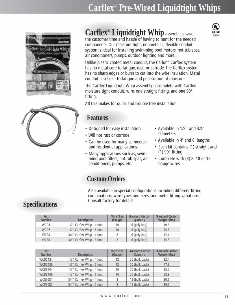
Carflex® Pre-Wired Liquidtight Whips
Specifications
Features
Part Wire Size Standard Carton Standard Carton Number Description (Gauge) Quantity Weight (lbs.)WCD4 1/2" Carflex Whip - 4 foot 10 6 (poly bag) 10.6WCD6 1/2" Carflex Whip - 6 foot 10 6 (poly bag) 15.8WCE4 3/4" Carflex Whip - 4 foot 8 6 (poly bag) 12.4WCE6 3/4" Carflex Whip - 6 foot 8 6 (poly bag) 15.8
Part Wire Size Standard Carton Standard Carton Number Description (Gauge) Quantity Weight (lbs.)
WCD3124 1/2" Carflex Whip - 4 foot 12 20 (bulk pack) 32.4WCD3126 1/2" Carflex Whip - 6 foot 12 20 (bulk pack) 47.9WCD3104 1/2" Carflex Whip - 4 foot 10 20 (bulk pack) 35.2WCD3106 1/2" Carflex Whip - 6 foot 10 20 (bulk pack) 52.8WCE3084 3/4" Carflex Whip - 4 foot 8 15 (bulk pack) 30.9WCE3086 3/4" Carflex Whip - 6 foot 8 15 (bulk pack) 39.6
Carflex® Liquidtight Whip assemblies save the customer time and hassle of having to hunt for the needed components. Our moisture tight, nonmetallic, flexible conduit system is ideal for installing swimming pool motors, hot tub spas,air conditioners, pumps, outdoor lighting and more.
Unlike plastic coated metal conduit, the Carlon® Carflex system has no metal core to fatigue, rust, or corrode. The Carflex systemhas no sharp edges or burrs to cut into the wire insulation. Metalconduit is subject to fatigue and penetration of moisture.
The Carflex Liquidtight Whip assembly is complete with Carflexmoisture tight conduit, wire, one straight fitting, and one 90°fitting.
All this makes for quick and trouble free installation.
• Designed for easy installation• Will not rust or corrode• Can be used for many commercial
and residential applications.• Many applications such as; swim-
ming pool filters, hot tub spas, airconditioners, pumps, etc.
• Available in 1/2" and 3/4" diameters
• Available in 4' and 6' lengths• Each kit contains (1) straight and
(1) 90° fitting• Complete with (3) 8, 10 or 12
gauge wires
E155504
Custom OrdersAlso available in special configurations including different fitting combinations, wire types and sizes, and metal fitting variations.Consult factory for details.
w w w . c a r l o n . c o m12
Carlon® Cord Grips – Straight PG Hubs
Specifications
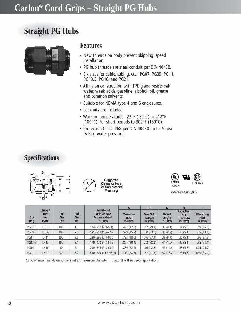
Straight PG Hubs
Features• New threads on body prevent skipping, speed
installation.• PG hub threads are steel conduit per DIN 40430.• Six sizes for cable, tubing, etc.: PG07, PG09, PG11,
PG13.5, PG16, and PG21.• All nylon construction with TPE gland resists salt
water, weak acids, gasoline, alcohol, oil, greaseand common solvents.
• Suitable for NEMA type 4 and 6 enclosures.• Locknuts are included.• Working temperatures: -22°F (-30ºC) to 212°F
(100°C). For short periods to 302°F (150°C).• Protection Class IP68 per DIN 40050 up to 70 psi
(5 Bar) water pressure.
A B C D EStraight Diameter of Wrenching
Part Std. Std. Cable or Wire Clearance Max O.A. Thread Nut WrenchingSize No. Ctn. Ctn. Accommodated Hole Length Length Thickness Flats(PG) Black Qty. Wt. in. (mm) in. (mm) in. (mm) in. (mm) in. (mm) in. (mm)
PG07 LH07 100 1.3 .114-.250 (2.9-6.4) .492 (12.5) 1.17 (29.7) .33 (8.4) .22 (5.6) .59 (15.0)
PG09 LH09 100 2.0 .181-.312 (4.6-7.9) .599 (15.2) 1.30 (33.0) .34 (8.6) .20 (5.1) .75 (19.1)
PG11 LH11 100 2.6 .230-.395 (5.8-10.0) .733 (18.6) 1.46 (37.1) .39 (9.9) .20 (5.1) .86 (21.8)
PG13.5 LH13 100 3.1 .170-.470 (4.3-11.9) .804 (20.4) 1.53 (38.9) .41 (10.4) .20 (5.1) .95 (24.1)
PG16 LH16 50 2.1 .230-.546 (5.8-13.9) .886 (22.5) 1.66 (42.2) .45 (11.4) .23 (5.8) 1.05 (26.7)
PG21 LH21 50 3.2 .450-.709 (11.4-18.0) 1.115 (28.3) 1.87 (47.5) .52 (13.2) .23 (5.8) 1.30 (33.0)
ASuggested
Clearance Hole For Nonthreaded
Mounting
B
E
CD
Patented 4,900,068
Carlon® recommends using the smallest maximum diameter fitting that will suit your application.
E51579LR93876
w w w . c a r l o n . c o m 13
Carlon® Cord Grips – Straight NPT Hubs
Specifications
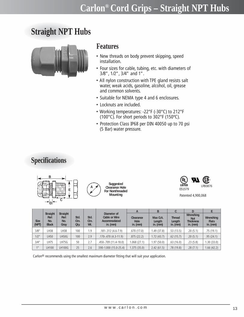
Straight NPT Hubs
Features• New threads on body prevent skipping, speed
installation.• Four sizes for cable, tubing, etc. with diameters of
3/8", 1/2", 3/4" and 1".• All nylon construction with TPE gland resists salt
water, weak acids, gasoline, alcohol, oil, greaseand common solvents.
• Suitable for NEMA type 4 and 6 enclosures.• Locknuts are included.• Working temperatures: -22°F (-30°C) to 212°F
(100°C). For short periods to 302°F (150ºC).• Protection Class IP68 per DIN 40050 up to 70 psi
(5 Bar) water pressure.
A B C D EStraight Straight Diameter of Wrenching
Part Part Std. Std. Cable or Wire Clearance Max O.A. Thread Nut WrenchingSize No. No. Ctn. Ctn. Accommodated Hole Length Length Thickness Flats
(NPT) Black Gray Qty. Wt. in. (mm) in. (mm) in. (mm) in. (mm) in. (mm) in. (mm)
3/8" LH38 LH38 100 1.9 .181-.312 (4.6-7.9) .670 (17.0) 1.49 (37.8) .53 (13.5) .20 (5.1) .75 (19.1)
1/2" LH50 LH50G 100 2.9 .170-.470 (4.3-11.9) .875 (22.2) 1.72 (43.7) .62 (15.7) .20 (5.1) .95 (24.1)
3/4" LH75 LH75G 50 2.7 .450-.709 (11.4-18.0) 1.068 (27.1) 1.97 (50.0) .63 (16.0) .23 (5.8) 1.30 (33.0)
1" LH100 LH100G 25 2.6 .590-1.000 (15.0-25.4) 1.375 (35.0) 2.42 (61.5) .78 (19.8) .28 (7.1) 1.66 (42.2)
Patented 4,900,068
Carlon® recommends using the smallest maximum diameter fitting that will suit your application.
E51579LR93876A
SuggestedClearance Hole
For NonthreadedMounting
B
E
CD

w w w . c a r l o n . c o m14

w w w . c a r l o n . c o m 15
Contractor KitsPlug-In Chime
Extend-A-ChimeAccessories
Carlon® Chimes
Wireless Plug-In Door Chimes
Plug-In Chimes Sound Options Available:
• Ding Dong • Dong • Westminster Chime • 12 Days of Christmas• Hail, Hail, The Gang’s All Here • My Country ‘Tis of Thee
RC3253 Plug-In Add-On Door Chime
• Six different selectable sounds• Includes two buttons• Different sounds for front,
back & other doors
RC3252 Plug-In Door Chime
RC3250 Plug-In Door Chime
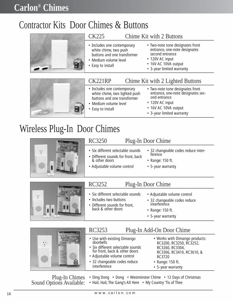
Contractor Kits Door Chimes & Buttons
CK221RP Chime Kit with 2 Lighted Buttons
• Includes one contemporarywhite chime, two push buttons and one transformer
• Medium volume level• Easy to install
CK225 Chime Kit with 2 Buttons• Two-note tone designates front
entrance, one-note designates second entrance
• 120V AC input• 16V AC 10VA output• 3-year limited warranty
• Six different selectable sounds• Different sounds for front, back
& other doors• Adjustable volume control
• 32 changeable codes reduce inter-ference
• Range: 150 ft.• 5-year warranty
• Adjustable volume control• 32 changeable codes reduce
interference• Range: 150 ft.• 5-year warranty
• Use with existing Dimango doorbells
• Six different selectable sounds for front, back & other doors
• Adjustable volume control• 32 changeable codes reduce
interference
• Works with Dimango products:RC3200, RC3250, RC3252,RC3260, RC3304,RC3306, RC3410, RC3610, &RC3720
• Range: 150 ft.• 5-year warranty
• Includes one contemporary white chime, two lighted pushbuttons and one transformer
• Medium volume level• Easy to install
• Two-note tone designates frontentrance, one-note designates sec-ond entrance
• 120V AC input• 16V AC 10VA output• 3-year limited warranty
w w w . c a r l o n . c o m16
Carlon® Chimes
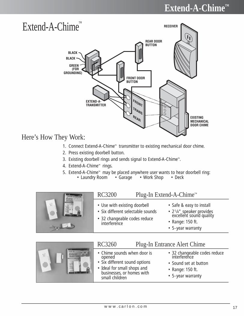
Extend-A-Chime™
1. Connect Extend-A-Chime™ transmitter to existing mechanical door chime.2. Press existing doorbell button.3. Existing doorbell rings and sends signal to Extend-A-Chime™.4. Extend-A-Chime™ rings.5. Extend-A-Chime™ may be placed anywhere user wants to hear doorbell ring:
• Laundry Room • Garage • Work Shop • Deck
RC3200 Plug-In Extend-A-Chime™
RC3260 Plug-In Entrance Alert Chime
Here’s How They Work:
• Use with existing doorbell• Six different selectable sounds
• 32 changeable codes reduce interference
• Safe & easy to install• 21/4" speaker provides
excellent sound quality• Range: 150 ft.• 5-year warranty
• Chime sounds when door isopened
• Six different sound options• Ideal for small shops and
businesses, or homes with small children
• 32 changeable codes reduce interference
• Sound set at button• Range: 150 ft.• 5-year warranty
w w w . c a r l o n . c o m 17
Extend-A-Chime™
Batteries
Transmitters
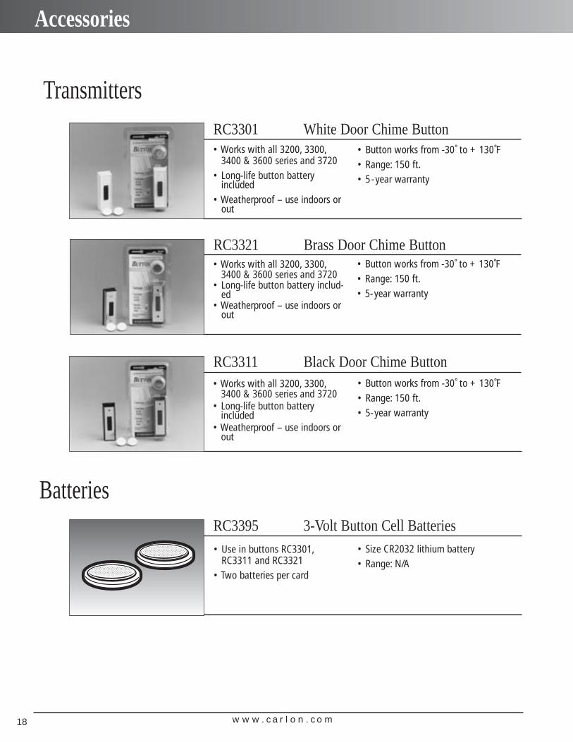
RC3395 3-Volt Button Cell Batteries
RC3321 Brass Door Chime Button
RC3311 Black Door Chime Button
RC3301 White Door Chime Button• Works with all 3200, 3300,
3400 & 3600 series and 3720• Long-life button battery
included• Weatherproof – use indoors or
out
• Button works from -30˚ to + 130˚F• Range: 150 ft.• 5-year warranty
• Button works from -30˚ to + 130˚F• Range: 150 ft.• 5-year warranty
• Works with all 3200, 3300,3400 & 3600 series and 3720
• Long-life button battery includ-ed
• Weatherproof – use indoors orout
• Works with all 3200, 3300,3400 & 3600 series and 3720
• Long-life button battery included
• Weatherproof – use indoors orout
• Button works from -30˚ to + 130˚F• Range: 150 ft.• 5-year warranty
• Use in buttons RC3301,RC3311 and RC3321
• Two batteries per card
• Size CR2032 lithium battery• Range: N/A
w w w . c a r l o n . c o m18
Accessories
w w w . c a r l o n . c o m 19
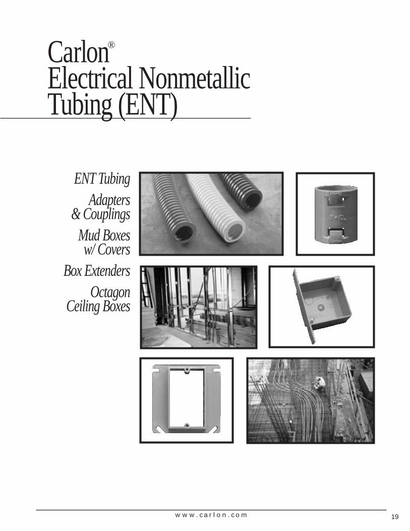
ENT TubingAdapters
& CouplingsMud Boxes w/ Covers
Box ExtendersOctagon
Ceiling Boxes
Carlon®
Electrical Nonmetallic Tubing (ENT)
w w w . c a r l o n . c o m20
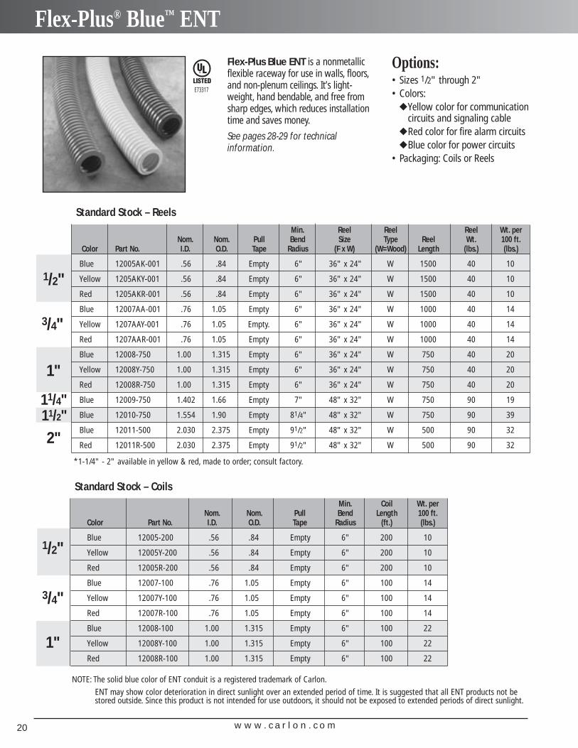
Flex-Plus® Blue™ ENT
Min. Coil Wt. perNom. Nom. Pull Bend Length 100 ft.
Color Part No. I.D. O.D. Tape Radius (ft.) (lbs.)
Blue 12005-200 .56 .84 Empty 6" 200 10
Yellow 12005Y-200 .56 .84 Empty 6" 200 10
Red 12005R-200 .56 .84 Empty 6" 200 10
Blue 12007-100 .76 1.05 Empty 6" 100 14
Yellow 12007Y-100 .76 1.05 Empty 6" 100 14
Red 12007R-100 .76 1.05 Empty 6" 100 14
Blue 12008-100 1.00 1.315 Empty 6" 100 22
Yellow 12008Y-100 1.00 1.315 Empty 6" 100 22
Red 12008R-100 1.00 1.315 Empty 6" 100 22
Standard Stock – Coils
1"
1/2"
3/4"
Flex-Plus Blue ENT is a nonmetallicflexible raceway for use in walls, floors,and non-plenum ceilings. It’s light-weight, hand bendable, and free fromsharp edges, which reduces installationtime and saves money.
See pages 28-29 for technical information.
E73317
Min. Reel Reel Reel Wt. perNom. Nom. Pull Bend Size Type Reel Wt. 100 ft.
Color Part No. I.D. O.D. Tape Radius (F x W) (W=Wood) Length (lbs.) (lbs.)
Blue 12005AK-001 .56 .84 Empty 6" 36" x 24" W 1500 40 10
Yellow 1205AKY-001 .56 .84 Empty 6" 36" x 24" W 1500 40 10
Red 1205AKR-001 .56 .84 Empty 6" 36" x 24" W 1500 40 10
Blue 12007AA-001 .76 1.05 Empty 6" 36" x 24" W 1000 40 14
Yellow 1207AAY-001 .76 1.05 Empty. 6" 36" x 24" W 1000 40 14
Red 1207AAR-001 .76 1.05 Empty 6" 36" x 24" W 1000 40 14
Blue 12008-750 1.00 1.315 Empty 6" 36" x 24" W 750 40 20
Yellow 12008Y-750 1.00 1.315 Empty 6" 36" x 24" W 750 40 20
Red 12008R-750 1.00 1.315 Empty 6" 36" x 24" W 750 40 20
Blue 12009-750 1.402 1.66 Empty 7" 48" x 32" W 750 90 19
Blue 12010-750 1.554 1.90 Empty 81/4" 48" x 32" W 750 90 39
Blue 12011-500 2.030 2.375 Empty 91/2" 48" x 32" W 500 90 32
Red 12011R-500 2.030 2.375 Empty 91/2" 48" x 32" W 500 90 32
1"
2"
11/4"
1/2"
3/4"
11/2"
Standard Stock – Reels
Options:• Sizes 1/2" through 2" • Colors:
◆ Yellow color for communicationcircuits and signaling cable
◆ Red color for fire alarm circuits◆ Blue color for power circuits
• Packaging: Coils or Reels
NOTE: The solid blue color of ENT conduit is a registered trademark of Carlon.
ENT may show color deterioration in direct sunlight over an extended period of time. It is suggested that all ENT products not bestored outside. Since this product is not intended for use outdoors, it should not be exposed to extended periods of direct sunlight.
*1-1/4" - 2" available in yellow & red, made to order; consult factory.
w w w . c a r l o n . c o m 21
Accessories
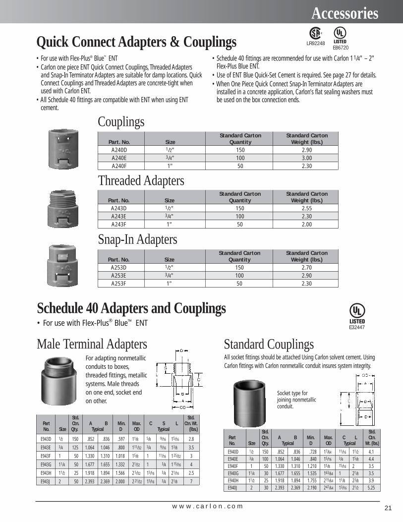
Male Terminal AdaptersFor adapting nonmetallicconduits to boxes,threaded fittings, metallicsystems. Male threads on one end, socket endon other.
Std. Std.Part Ctn. A B Min. Max. C S L Ctn. Wt.No. Size Qty. Typical D OD Typical (lbs.)
E943D 1/2 150 .852 .836 .597 11/8 5/8 9/16 15/16 2.8
E943E 3/4 125 1.064 1.046 .800 111/32 3/4 9/16 13/8 3.5
E943F 1 50 1.330 1.310 1.018 15/8 1 11/16 125/32 3
E943G 11/4 50 1.677 1.655 1.332 21/32 1 3/4 115/16 4
E943H 11/2 25 1.918 1.894 1.566 2 5/32 13/16 3/4 21/16 2.5
E943J 2 50 2.393 2.369 2.000 2 21/32 13/16 3/4 21/8 7
Std. Std.Part Ctn. A B Min. Max. C L Ctn.No. Size Qty. Typical D OD Typical Wt. (lbs.)
E940D 1/2 150 .852 .836 .728 17/64 11/16 11/2 4.1E940E 3/4 100 1.064 1.046 .840 15/16 3/4 15/8 4.4E940F 1 50 1.330 1.310 1.210 15/8 15/16 2 3.5E940G 11/4 30 1.677 1.655 1.535 163/64 1 21/8 3.5E940H 11/2 25 1.918 1.894 1.755 215/64 11/8 23/8 3.9E940J 2 30 2.393 2.369 2.190 247/64 13/16 21/2 5.25
All socket fittings should be attached Using Carlon solvent cement. UsingCarlon fittings with Carlon nonmetallic conduit insures system integrity.
Standard Couplings
Socket type for joining nonmetallic conduit.
Schedule 40 Adapters and Couplings• For use with Flex-Plus® Blue™ ENT
• For use with Flex-Plus® Blue™ ENT• Carlon one piece ENT Quick Connect Couplings, Threaded Adapters
and Snap-In Terminator Adapters are suitable for damp locations. QuickConnect Couplings and Threaded Adapters are concrete-tight whenused with Carlon ENT.
• All Schedule 40 fittings are compatible with ENT when using ENTcement.
• Schedule 40 fittings are recommended for use with Carlon 11/4" – 2"Flex-Plus Blue ENT.
• Use of ENT Blue Quick-Set Cement is required. See page 27 for details.• When One Piece Quick Connect Snap-In Terminator Adapters are
installed in a concrete application, Carlon’s flat sealing washers mustbe used on the box connection ends.
Quick Connect Adapters & Couplings
Standard Carton Standard CartonPart. No. Size Quantity Weight (lbs.)
A240D 1/2" 150 2.90A240E 3/4" 100 3.00A240F 1" 50 2.30
Couplings
Standard Carton Standard CartonPart. No. Size Quantity Weight (lbs.)
A243D 1/2" 150 2.55A243E 3/4" 100 2.30A243F 1" 50 2.00
Threaded Adapters
Standard Carton Standard CartonPart. No. Size Quantity Weight (lbs.)
A253D 1/2" 150 2.70A253E 3/4" 100 2.90A253F 1" 50 2.30
Snap-In Adapters
LR92248E86720
E32447
w w w . c a r l o n . c o m22
Accessories
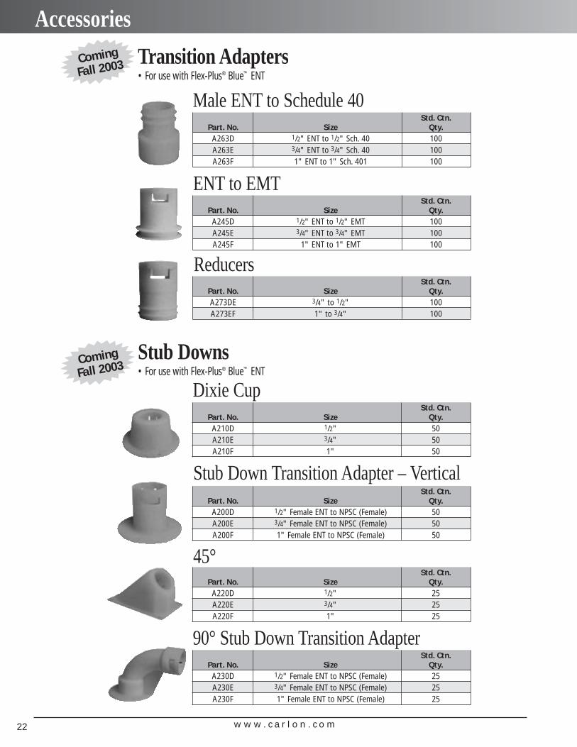
• For use with Flex-Plus® Blue™ ENTTransition Adapters
Std. Ctn.Part. No. Size Qty.
A263D 1/2" ENT to 1/2" Sch. 40 100A263E 3/4" ENT to 3/4" Sch. 40 100A263F 1" ENT to 1" Sch. 401 100
Male ENT to Schedule 40
Std. Ctn.Part. No. Size Qty.
A245D 1/2" ENT to 1/2" EMT 100A245E 3/4" ENT to 3/4" EMT 100A245F 1" ENT to 1" EMT 100
ENT to EMT
Std. Ctn.Part. No. Size Qty.A273DE 3/4" to 1/2" 100A273EF 1" to 3/4" 100
Reducers
• For use with Flex-Plus® Blue™ ENTStub Downs
Std. Ctn.Part. No. Size Qty.
A210D 1/2" 50A210E 3/4" 50A210F 1" 50
Dixie Cup
Std. Ctn.Part. No. Size Qty.
A200D 1/2" Female ENT to NPSC (Female) 50A200E 3/4" Female ENT to NPSC (Female) 50A200F 1" Female ENT to NPSC (Female) 50
Stub Down Transition Adapter – Vertical
Std. Ctn.Part. No. Size Qty.
A220D 1/2" 25A220E 3/4" 25A220F 1" 25
45°
Std. Ctn.Part. No. Size Qty.
A230D 1/2" Female ENT to NPSC (Female) 25A230E 3/4" Female ENT to NPSC (Female) 25A230F 1" Female ENT to NPSC (Female) 25
90° Stub Down Transition Adapter
Coming
Fall 2003
Coming
Fall 2003
w w w . c a r l o n . c o m 23
Accessories
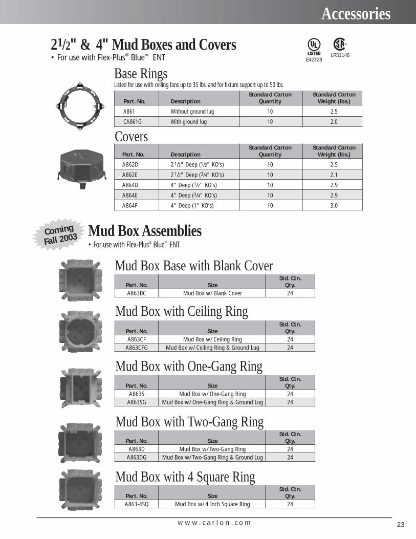
• For use with Flex-Plus® Blue™ ENT21/2" & 4" Mud Boxes and Covers
Standard Carton Standard CartonPart. No. Description Quantity Weight (lbs.)
A861 Without ground lug 10 2.5
CA861G With ground lug 10 2.0
Base RingsListed for use with ceiling fans up to 35 lbs. and for fixture support up to 50 lbs.
Standard Carton Standard CartonPart. No. Description Quantity Weight (lbs.)
A862D 2 1/2" Deep (1/2" KO’s) 10 2.5
A862E 2 1/2" Deep (3/4" KO’s) 10 2.1
A864D 4" Deep (1/2" KO’s) 10 2.9
A864E 4" Deep (3/4" KO’s) 10 2.9
A864F 4" Deep (1" KO’s) 10 3.0
Covers
E42728LR31146
• For use with Flex-Plus® Blue™ ENTMud Box Assemblies
Std. Ctn.Part. No. Size Qty.A863BC Mud Box w/ Blank Cover 24
Mud Box Base with Blank Cover
Std. Ctn.Part. No. Size Qty.A863CF Mud Box w/ Ceiling Ring 24
A863CFG Mud Box w/ Ceiling Ring & Ground Lug 24
Mud Box with Ceiling Ring
Std. Ctn.Part. No. Size Qty.
A863S Mud Box w/ One-Gang Ring 24A863SG Mud Box w/ One-Gang Ring & Ground Lug 24
Mud Box with One-Gang Ring
Std. Ctn.Part. No. Size Qty.
A863D Mud Box w/ Two-Gang Ring 24A863DG Mud Box w/ Two-Gang Ring & Ground Lug 24
Mud Box with Two-Gang Ring
Std. Ctn.Part. No. Size Qty.A863-4SQ Mud Box w/ 4 Inch Square Ring 24
Mud Box with 4 Square Ring
Coming
Fall 2003
w w w . c a r l o n . c o m24
Accessories
• For use with Flex-Plus® Blue™ ENT• Suitable for masonry walls
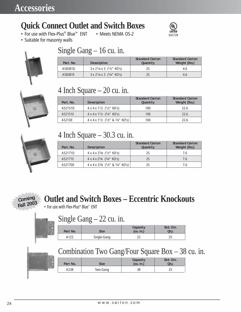
• Meets NEMA OS-2Quick Connect Outlet and Switch Boxes
Standard Carton Standard CartonPart. No. Description Quantity Weight (lbs.)
A58381D 3 x 21/4 x 3 (1/2" KO’s) 25 4.6
A58381E 3 x 21/4 x 3 (3/4" KO’s) 25 4.6
Single Gang – 16 cu. in.
Standard Carton Standard CartonPart. No. Description Quantity Weight (lbs.)
A52151D 4 x 4 x 11/2 (1/2" KO’s) 100 22.6
A52151E 4 x 4 x 11/2 (3/4" KO’s) 100 22.6
A521DE 4 x 4 x 11/2 (1/2" & 3/4" KO’s) 100 22.6
4 Inch Square – 20 cu. in.
Standard Carton Standard CartonPart. No. Description Quantity Weight (lbs.)
A52171D 4 x 4 x 23/8 (1/2" KO’s) 25 7.6
A52171E 4 x 4 x 23/8 (3/4" KO’s) 25 7.6
A5217DE 4 x 4 x 23/8 (1/2" & 3/4" KO’s) 25 7.6
4 Inch Square – 30.3 cu. in.
E42728
Capacity Std. Ctn.Part No. Size (cu. in.) Qty.
A122 Single-Gang 22 25
Single Gang – 22 cu. in.
Capacity Std. Ctn.Part No. Size (cu. in.) Qty.
A238 Two-Gang 38 25
Combination Two Gang/Four Square Box – 38 cu. in.
• For use with Flex-Plus® Blue™ ENTOutlet and Switch Boxes – Eccentric KnockoutsComing
Fall 2003
w w w . c a r l o n . c o m 25
Accessories
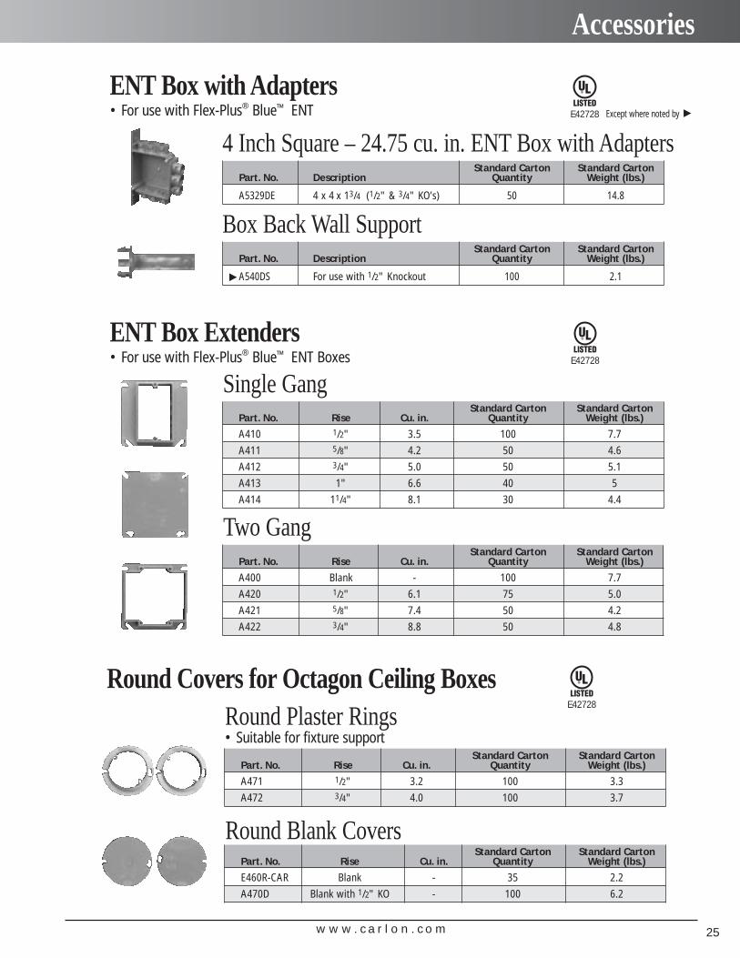
• For use with Flex-Plus® Blue™ ENTENT Box with Adapters
Standard Carton Standard CartonPart. No. Description Quantity Weight (lbs.)
A5329DE 4 x 4 x 13/4 (1/2" & 3/4" KO’s) 50 14.8
4 Inch Square – 24.75 cu. in. ENT Box with Adapters
Standard Carton Standard CartonPart. No. Description Quantity Weight (lbs.)
A540DS For use with 1/2" Knockout 100 2.1
Box Back Wall Support
• For use with Flex-Plus® Blue™ ENT BoxesENT Box Extenders
Standard Carton Standard CartonPart. No. Rise Cu. in. Quantity Weight (lbs.)
A410 1/2" 3.5 100 7.7
A411 5/8" 4.2 50 4.6
A412 3/4" 5.0 50 5.1
A413 1" 6.6 40 5
A414 11/4" 8.1 30 4.4
Single Gang
Standard Carton Standard CartonPart. No. Rise Cu. in. Quantity Weight (lbs.)
A400 Blank - 100 7.7
A420 1/2" 6.1 75 5.0
A421 5/8" 7.4 50 4.2
A422 3/4" 8.8 50 4.8
Two Gang
E42728
E42728
Except where noted by
▲
▲
Round Covers for Octagon Ceiling BoxesE42728
Standard Carton Standard CartonPart. No. Rise Cu. in. Quantity Weight (lbs.)
A471 1/2" 3.2 100 3.3
A472 3/4" 4.0 100 3.7
Round Plaster Rings• Suitable for fixture support
Standard Carton Standard CartonPart. No. Rise Cu. in. Quantity Weight (lbs.)
E460R-CAR Blank - 35 2.2
A470D Blank with 1/2" KO - 100 6.2
Round Blank Covers
w w w . c a r l o n . c o m26
Accessories
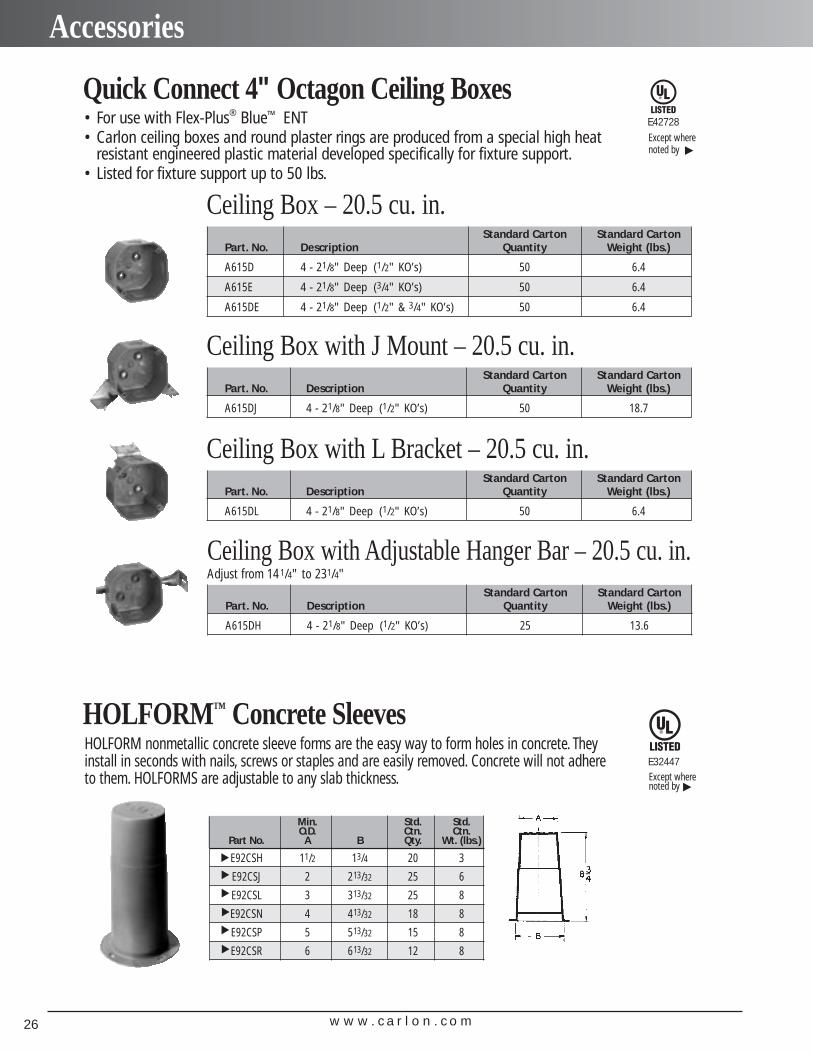
• For use with Flex-Plus® Blue™ ENT• Carlon ceiling boxes and round plaster rings are produced from a special high heat
resistant engineered plastic material developed specifically for fixture support.• Listed for fixture support up to 50 lbs.
Quick Connect 4" Octagon Ceiling Boxes
Standard Carton Standard CartonPart. No. Description Quantity Weight (lbs.)
A615D 4 - 21/8" Deep (1/2" KO’s) 50 6.4
A615E 4 - 21/8" Deep (3/4" KO’s) 50 6.4
A615DE 4 - 21/8" Deep (1/2" & 3/4" KO’s) 50 6.4
Ceiling Box – 20.5 cu. in.
Standard Carton Standard CartonPart. No. Description Quantity Weight (lbs.)
A615DJ 4 - 21/8" Deep (1/2" KO’s) 50 18.7
Ceiling Box with J Mount – 20.5 cu. in.
E42728
Standard Carton Standard CartonPart. No. Description Quantity Weight (lbs.)
A615DL 4 - 21/8" Deep (1/2" KO’s) 50 6.4
Ceiling Box with L Bracket – 20.5 cu. in.
Ceiling Box with Adjustable Hanger Bar – 20.5 cu. in.Adjust from 141/4" to 231/4"
Standard Carton Standard CartonPart. No. Description Quantity Weight (lbs.)
A615DH 4 - 21/8" Deep (1/2" KO’s) 25 13.6
Except where noted by
▲
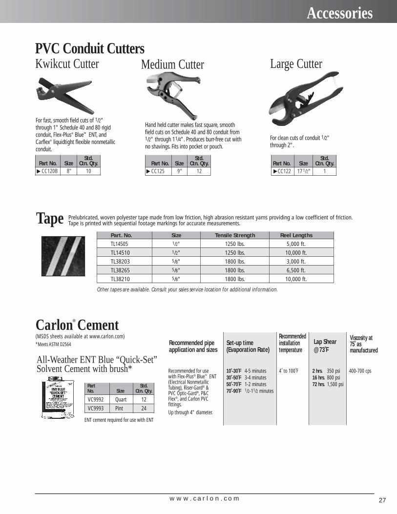
HOLFORM nonmetallic concrete sleeve forms are the easy way to form holes in concrete. Theyinstall in seconds with nails, screws or staples and are easily removed. Concrete will not adhereto them. HOLFORMS are adjustable to any slab thickness.
HOLFORM™ Concrete Sleeves
Min. Std. Std.O.D. Ctn. Ctn.
Part No. A B Qty. Wt. (lbs.)
E92CSH 11/2 13/4 20 3
E92CSJ 2 213/32 25 6
E92CSL 3 313/32 25 8
E92CSN 4 413/32 18 8
E92CSP 5 513/32 15 8
E92CSR 6 613/32 12 8
▲▲
▲▲
▲▲
E32447
▲Except wherenoted by
w w w . c a r l o n . c o m 27
Accessories
Std.Part No. Size Ctn. Qty.
CC120B 8" 10
Std.Part No. Size Ctn. Qty.CC125 9" 12
Std.Part No. Size Ctn. Qty.
CC122 17 1/2" 1
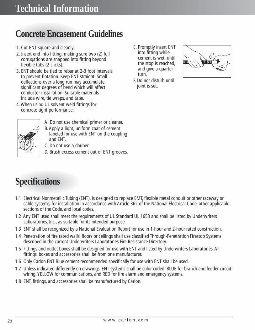
PVC Conduit Cutters
Hand held cutter makes fast square, smoothfield cuts on Schedule 40 and 80 conduit from1/2" through 11/4". Produces burr-free cut withno shavings. Fits into pocket or pouch.
For clean cuts of conduit 1/2"through 2".
For fast, smooth field cuts of 1/2"through 1" Schedule 40 and 80 rigidconduit, Flex-Plus® Blue™ ENT, andCarflex® liquidtight flexible nonmetallicconduit.
Kwikcut Cutter Medium Cutter Large Cutter
▲ ▲ ▲
Carlon® Cement (MSDS sheets available at www.carlon.com)*Meets ASTM D2564
All-Weather ENT Blue “Quick-Set”Solvent Cement with brush* Recommended for use
with Flex-Plus® Blue™ ENT(Electrical NonmetallicTubing), Riser-Gard® &PVC Optic-Gard®, P&CFlex®, and Carlon PVC fittings.Up through 4" diameter.
Recommended pipeapplication and sizes
10˚-30˚F 4-5 minutes30˚-50˚F 3-4 minutes50˚-70˚F 1-2 minutes70˚-90˚F 1/2-11/2 minutes
2 hrs. 350 psi16 hrs. 800 psi72 hrs. 1,500 psi
Set-up time(Evaporation Rate)
Lap Shear@ 73˚F
Recommendedinstallation temperature
4˚ to 100˚F
Viscosity at 75˚ asmanufactured
400-700 cps
Part Std.No. Size Ctn. Qty.
VC9992 Quart 12
VC9993 Pint 24
Other tapes are available. Consult your sales service location for additional information.
Prelubricated, woven polyester tape made from low friction, high abrasion resistant yarns providing a low coefficient of friction.Tape is printed with sequential footage markings for accurate measurements.Tape
Part. No. Size Tensile Strength Reel Lengths
TL14505 1/2" 1250 lbs. 5,000 ft.
TL14510 1/2" 1250 lbs. 10,000 ft.
TL38203 5/8" 1800 lbs. 3,000 ft.
TL38265 5/8" 1800 lbs. 6,500 ft.
TL38210 5/8" 1800 lbs. 10,000 ft.
ENT cement required for use with ENT
w w w . c a r l o n . c o m28
Technical Information
Concrete Encasement Guidelines
Specifications
1.1 Electrical Nonmetallic Tubing (ENT), is designed to replace EMT, flexible metal conduit or other raceway orcable systems, for installation in accordance with Article 362 of the National Electrical Code, other applicablesections of the Code, and local codes.
1.2 Any ENT used shall meet the requirements of UL Standard UL 1653 and shall be listed by UnderwritersLaboratories, Inc., as suitable for its intended purpose.
1.3 ENT shall be recognized by a National Evaluation Report for use in 1-hour and 2-hour rated construction.1.4 Penetration of fire rated walls, floors or ceilings shall use classified Through-Penetration Firestop Systems
described in the current Underwriters Laboratories Fire Resistance Directory.1.5 Fittings and outlet boxes shall be designed for use with ENT and listed by Underwriters Laboratories. All
fittings, boxes and accessories shall be from one manufacturer.1.6 Only Carlon ENT Blue cement recommended specifically for use with ENT shall be used.1.7 Unless indicated differently on drawings, ENT systems shall be color coded: BLUE for branch and feeder circuit
wiring, YELLOW for communications, and RED for fire alarm and emergency systems.1.8 ENT, fittings, and accessories shall be manufactured by Carlon.
1. Cut ENT square and cleanly.2. Insert end into fitting, making sure two (2) full
corrugations are snapped into fitting beyondflexible tabs (2 clicks).
3. ENT should be tied to rebar at 2-3 foot intervalsto prevent flotation. Keep ENT straight. Smalldeflections over a long run may accumulate significant degrees of bend which will affectconductor installation. Suitable materialsinclude wire, tie wraps, and tape.
4. When using UL solvent weld fittings for concrete tight performance:
A. Do not use chemical primer or cleaner.B. Apply a light, uniform coat of cement
labeled for use with ENT on the couplingand ENT.
C. Do not use a dauber.D. Brush excess cement out of ENT grooves.
E. Promptly insert ENTinto fitting whilecement is wet, untilthe stop is reached,and give a quarterturn.
F. Do not disturb untiljoint is set.
w w w . c a r l o n . c o m 29
Technical Information
FEATURES:• UL recognizes the use of PVC Schedule 40 cement type fittings with all sizes of ENT• ENT rated for 90 deg C conductors• One piece ENT Coupling, Threaded Terminator and Schedule 40 Transition Fitting are rated concrete tight
without tape by UL• Recognized for use in 2-hour fire resistive nonload bearing and load bearing wall assemblies per NER-290• Recognized for use in 1-hour fire resistive nonload bearing wall assemblies per NER-290• Recognized for use in a fire resistive ceiling assembly (up to 3 hours) per NER-290• Recognized for Through-Penetration Firestop systems as classified by UL to meet BOCA, SBCCI and ICBO codes.• Conductors easily push through the raceway (up to approximately 50 feet)*• For use in buildings in accordance with NEC Article 362• Recognized by ICC, BOCA, SBCCI, and ICBO for having a one and two hour fire rated wall assembly and up to a
three hour rated floor/ceiling assembly• Outside Diameters meet IPS Dimensions• Storage -4°F – 158°F• Handling -4°F – 104°F
APPROVED USES:• Concrete slab – NEC Article 362• Walls - wood stud, masonry and metal stud – NEC Article 362.• Ceilings - permanent or dropped (free air only) – NEC Article 362.• Exposed – NEC Article 362• Public Assembly – NEC Section 518.4, in nonfire rated and certain five rated structures• Prewired – NEC Article 362• Classified by UL 1479 for Through Penetration Firestop Systems in UL Guide Category XHEZ and current
UL Fire Resistance Directory• Three hour rated floor/ceiling assemble• Raised Floors – NEC Section 645.5(D)(2)• Exposed or concealed in building above three floors when a fire sprinkler system is installed in accordance with
NFPA 13 – NEC Section 362.10(2)
TYPICAL APPLICATIONS:• Residential: Low or high rise – multi or single family• Commercial: Low or high rise – office, retail, hotel/motel, restaurant, etc.• Nursing Homes/Hospitals in nonpatient care areas only• Schools, classrooms, dormitories, offices• Fire Alarm Systems• Recreational vehicles and parks• Solar Photovoltaic systems• Marinas and boatyards• Other uses per the current NEC

w w w . c a r l o n . c o m30
w w w . c a r l o n . c o m 31
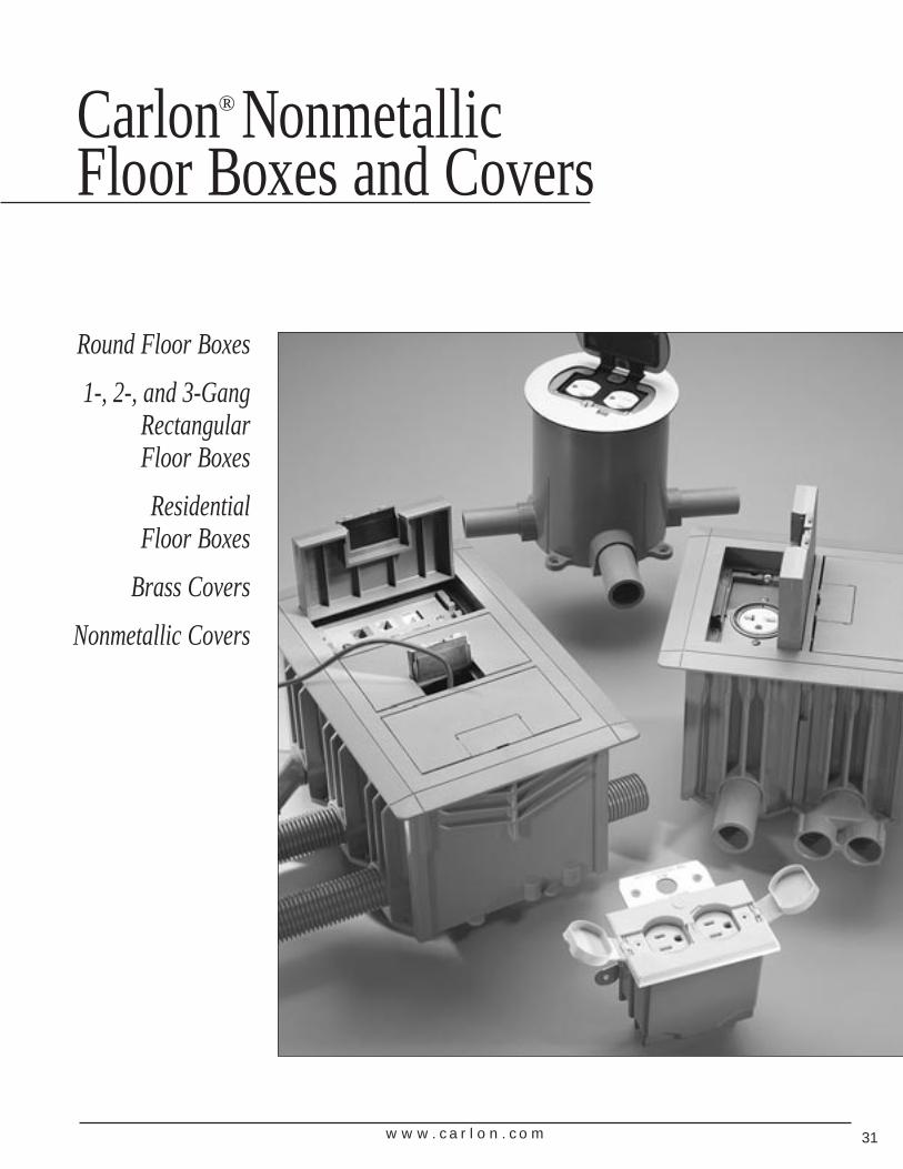
Round Floor Boxes
1-, 2-, and 3-GangRectangular Floor Boxes
Residential Floor Boxes
Brass Covers
Nonmetallic Covers
Carlon® NonmetallicFloor Boxes and Covers
w w w . c a r l o n . c o m32
Nonmetallic Rectangular Floor Boxes
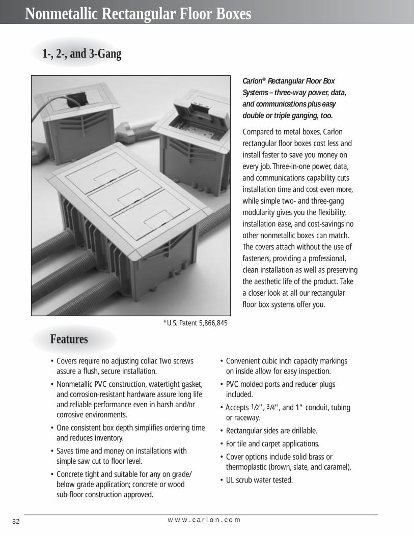
Carlon® Rectangular Floor BoxSystems – three-way power, data,and communications plus easy double or triple ganging, too.
Compared to metal boxes, Carlon rectangular floor boxes cost less andinstall faster to save you money onevery job. Three-in-one power, data,and communications capability cutsinstallation time and cost even more,while simple two- and three-gangmodularity gives you the flexibility,installation ease, and cost-savings noother nonmetallic boxes can match.The covers attach without the use offasteners, providing a professional,clean installation as well as preservingthe aesthetic life of the product. Takea closer look at all our rectangularfloor box systems offer you.
Features
• Covers require no adjusting collar. Two screwsassure a flush, secure installation.
• Nonmetallic PVC construction, watertight gasket,and corrosion-resistant hardware assure long lifeand reliable performance even in harsh and/or corrosive environments.
• One consistent box depth simplifies ordering timeand reduces inventory.
• Saves time and money on installations with simple saw cut to floor level.
• Concrete tight and suitable for any on grade/below grade application; concrete or wood sub-floor construction approved.
• Convenient cubic inch capacity markingson inside allow for easy inspection.
• PVC molded ports and reducer plugsincluded.
• Accepts 1/2", 3/4", and 1" conduit, tubingor raceway.
• Rectangular sides are drillable.
• For tile and carpet applications.
• Cover options include solid brass or thermoplastic (brown, slate, and caramel).
• UL scrub water tested.
*U.S. Patent 5,866,845
1-, 2-, and 3-Gang
w w w . c a r l o n . c o m 33
Nonmetallic Rectangular Floor Boxes
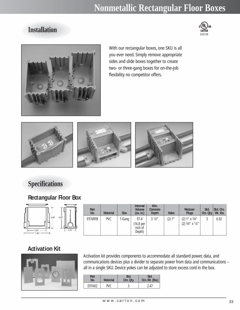
Installation
Specifications
With our rectangular boxes, one SKU is allyou ever need. Simply remove appropriatesides and slide boxes together to createtwo- or three-gang boxes for on-the-jobflexibility no competitor offers.
Activation kit provides components to accommodate all standard power, data, and communications devices plus a divider to separate power from data and communications –all in a single SKU. Device yokes can be adjusted to store excess cord in the box.
6.00"
5.50"7.46"
6.00"
3.25"
Rectangular Floor Box
Activation Kit
Internal Min.Part Volume Concrete Reducer Std. Std. Ctn.No. Material Size (cu. in.) Depth Hubs Plugs Ctn. Qty. Wt. lbs.
E976RFB PVC 1-Gang 97.4 3 1/2" (2) 1" (2) 1" x 3/4" 3 6.92(2) 3/4" x 1/2"(16.8 per
inch ofDepth)
Part Std. Std.No. Material Ctn. Qty. Ctn. Wt. (lbs.)
E97AK2 PVC 3 2.47
E42728
w w w . c a r l o n . c o m34
Rectangular Floor Box Covers – Nonmetallic
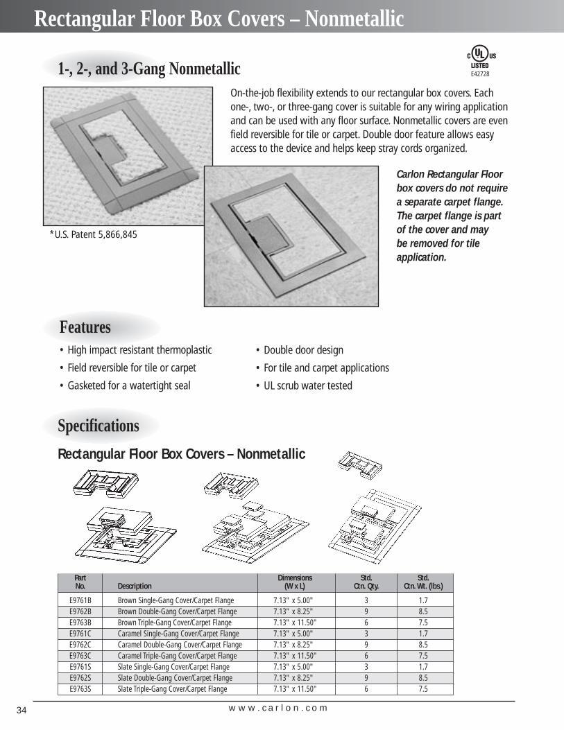
On-the-job flexibility extends to our rectangular box covers. Eachone-, two-, or three-gang cover is suitable for any wiring applicationand can be used with any floor surface. Nonmetallic covers are evenfield reversible for tile or carpet. Double door feature allows easyaccess to the device and helps keep stray cords organized.
1-, 2-, and 3-Gang Nonmetallic
Specifications
Rectangular Floor Box Covers – Nonmetallic
Part Dimensions Std. Std.No. Description (W x L) Ctn. Qty. Ctn. Wt. (lbs.)
E9761B Brown Single-Gang Cover/Carpet Flange 7.13" x 5.00" 3 1.7E9762B Brown Double-Gang Cover/Carpet Flange 7.13" x 8.25" 9 8.5E9763B Brown Triple-Gang Cover/Carpet Flange 7.13" x 11.50" 6 7.5E9761C Caramel Single-Gang Cover/Carpet Flange 7.13" x 5.00" 3 1.7E9762C Caramel Double-Gang Cover/Carpet Flange 7.13" x 8.25" 9 8.5E9763C Caramel Triple-Gang Cover/Carpet Flange 7.13" x 11.50" 6 7.5E9761S Slate Single-Gang Cover/Carpet Flange 7.13" x 5.00" 3 1.7E9762S Slate Double-Gang Cover/Carpet Flange 7.13" x 8.25" 9 8.5E9763S Slate Triple-Gang Cover/Carpet Flange 7.13" x 11.50" 6 7.5
Features• High impact resistant thermoplastic
• Field reversible for tile or carpet
• Gasketed for a watertight seal
• Double door design
• For tile and carpet applications
• UL scrub water tested
E42728
*U.S. Patent 5,866,845
Carlon Rectangular Floorbox covers do not requirea separate carpet flange.The carpet flange is partof the cover and may be removed for tile application.
w w w . c a r l o n . c o m 35
Rectangular Floor Box Covers – Brass
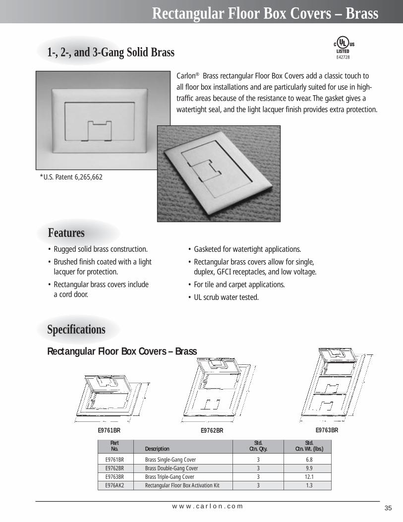
Carlon® Brass rectangular Floor Box Covers add a classic touch to all floor box installations and are particularly suited for use in high-traffic areas because of the resistance to wear. The gasket gives awatertight seal, and the light lacquer finish provides extra protection.
1-, 2-, and 3-Gang Solid Brass
Features• Rugged solid brass construction.
• Brushed finish coated with a light lacquer for protection.
• Rectangular brass covers include a cord door.
• Gasketed for watertight applications.
• Rectangular brass covers allow for single,duplex, GFCI receptacles, and low voltage.
• For tile and carpet applications.
• UL scrub water tested.
Specifications
Rectangular Floor Box Covers – Brass
Part Std. Std.No. Description Ctn. Qty. Ctn. Wt. (lbs.)
E9761BR Brass Single-Gang Cover 3 6.8E9762BR Brass Double-Gang Cover 3 9.9E9763BR Brass Triple-Gang Cover 3 12.1E976AK2 Rectangular Floor Box Activation Kit 3 1.3
E42728
E9761BR E9762BR E9763BR
*U.S. Patent 6,265,662
w w w . c a r l o n . c o m36
Nonmetallic Round Floor Boxes
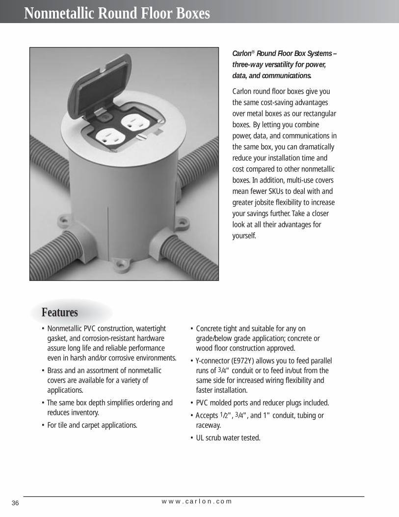
Carlon® Round Floor Box Systems –three-way versatility for power,data, and communications.
Carlon round floor boxes give youthe same cost-saving advantagesover metal boxes as our rectangularboxes. By letting you combinepower, data, and communications inthe same box, you can dramaticallyreduce your installation time andcost compared to other nonmetallicboxes. In addition, multi-use coversmean fewer SKUs to deal with andgreater jobsite flexibility to increaseyour savings further. Take a closerlook at all their advantages foryourself.
Features• Nonmetallic PVC construction, watertight
gasket, and corrosion-resistant hardwareassure long life and reliable performanceeven in harsh and/or corrosive environments.
• Brass and an assortment of nonmetallic covers are available for a variety of applications.
• The same box depth simplifies ordering andreduces inventory.
• For tile and carpet applications.
• Concrete tight and suitable for any ongrade/below grade application; concrete orwood floor construction approved.
• Y-connector (E972Y) allows you to feed parallelruns of 3/4" conduit or to feed in/out from thesame side for increased wiring flexibility andfaster installation.
• PVC molded ports and reducer plugs included.
• Accepts 1/2", 3/4", and 1" conduit, tubing orraceway.
• UL scrub water tested.
w w w . c a r l o n . c o m 37
Nonmetallic Round Floor Boxes
Specifications
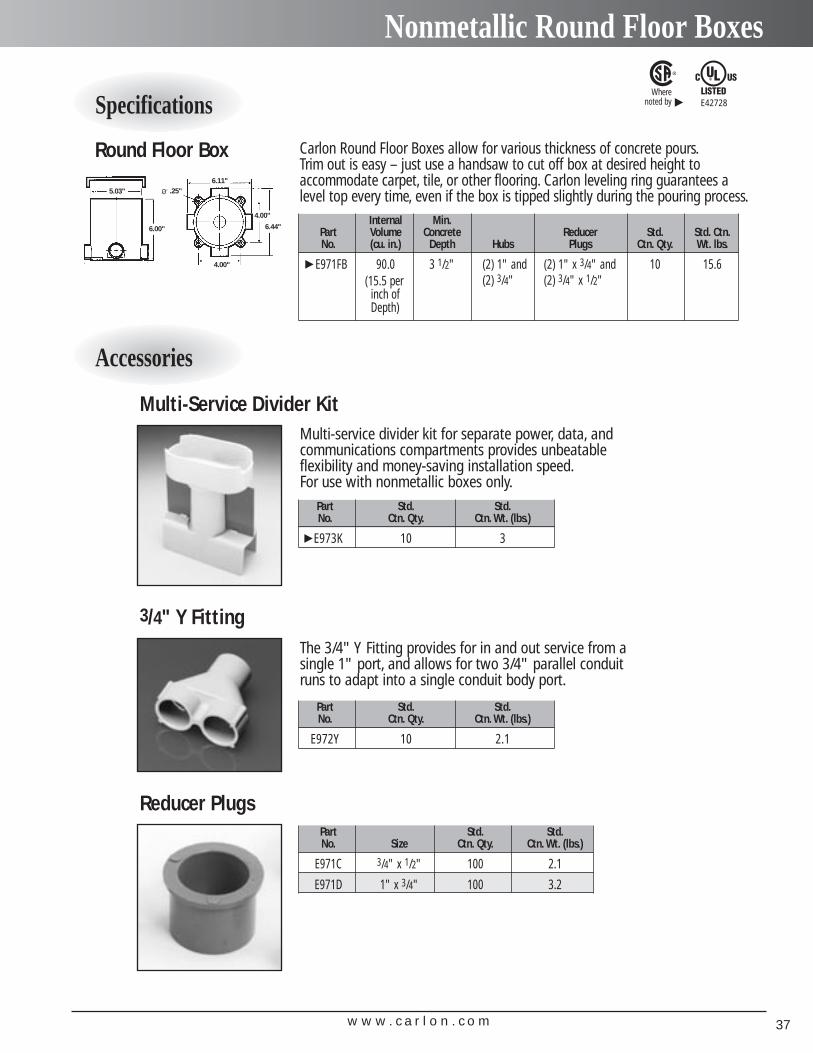
Round Floor Box
Accessories
Multi-Service Divider Kit
Internal Min.Part Volume Concrete Reducer Std. Std. Ctn.No. (cu. in.) Depth Hubs Plugs Ctn. Qty. Wt. lbs.
E971FB 90.0 3 1/2" (2) 1" and (2) 1" x 3/4" and 10 15.6(2) 3/4" (2) 3/4" x 1/2"(15.5 per
inch ofDepth)
6.11"
4.00"
6.44"
O .25"5.03"
6.00"
4.00"
Multi-service divider kit for separate power, data, andcommunications compartments provides unbeatableflexibility and money-saving installation speed.For use with nonmetallic boxes only.
The 3/4" Y Fitting provides for in and out service from asingle 1" port, and allows for two 3/4" parallel conduitruns to adapt into a single conduit body port.
Part Std. Std.No. Ctn. Qty. Ctn. Wt. (lbs.)
E973K 10 3
3/4" Y Fitting
Part Std. Std.No. Ctn. Qty. Ctn. Wt. (lbs.)
E972Y 10 2.1
Reducer PlugsPart Std. Std.No. Size Ctn. Qty. Ctn. Wt. (lbs.)
E971C 3/4" x 1/2" 100 2.1
E971D 1" x 3/4" 100 3.2
E42728Where
noted by
▲
▲▲
Carlon Round Floor Boxes allow for various thickness of concrete pours.Trim out is easy – just use a handsaw to cut off box at desired height to accommodate carpet, tile, or other flooring. Carlon leveling ring guarantees a level top every time, even if the box is tipped slightly during the pouring process.
w w w . c a r l o n . c o m38
Round Floor Box Covers – Nonmetallic
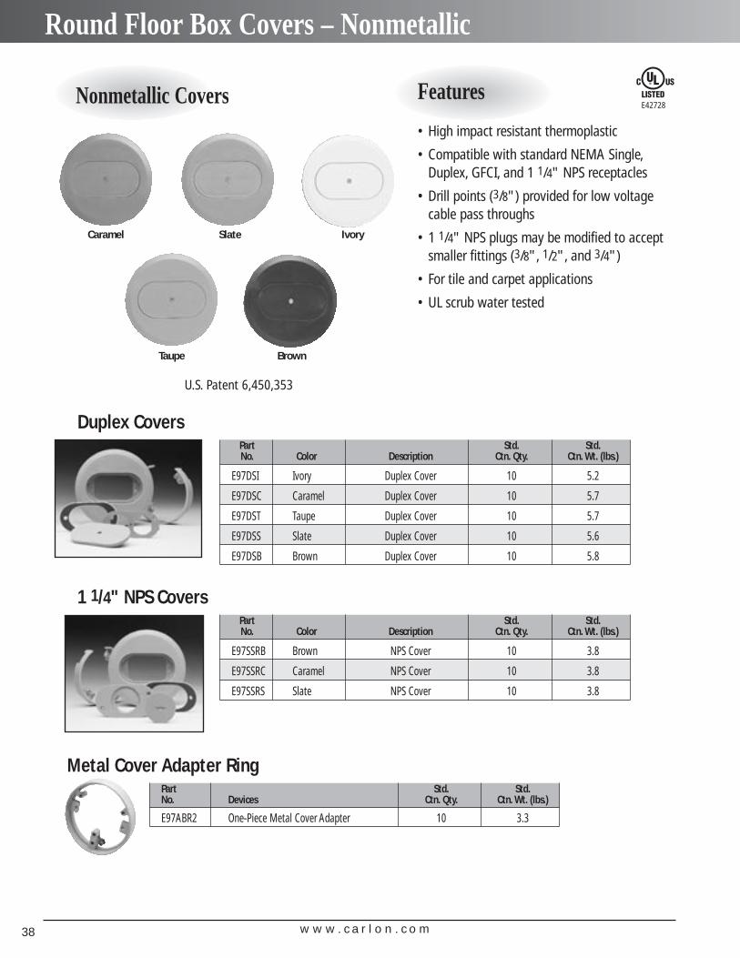
Nonmetallic Covers Features
• High impact resistant thermoplastic
• Compatible with standard NEMA Single,Duplex, GFCI, and 1 1/4" NPS receptacles
• Drill points (3/8") provided for low voltagecable pass throughs
• 1 1/4" NPS plugs may be modified to acceptsmaller fittings (3/8", 1/2", and 3/4")
• For tile and carpet applications
• UL scrub water tested
Part Std. Std.No. Color Description Ctn. Qty. Ctn. Wt. (lbs.)
E97DSI Ivory Duplex Cover 10 5.2
E97DSC Caramel Duplex Cover 10 5.7
E97DST Taupe Duplex Cover 10 5.7
E97DSS Slate Duplex Cover 10 5.6
E97DSB Brown Duplex Cover 10 5.8
Duplex Covers
Part Std. Std.No. Color Description Ctn. Qty. Ctn. Wt. (lbs.)
E97SSRB Brown NPS Cover 10 3.8
E97SSRC Caramel NPS Cover 10 3.8
E97SSRS Slate NPS Cover 10 3.8
1 1/4" NPS Covers
Caramel Slate Ivory
Taupe Brown
Part Std. Std.No. Devices Ctn. Qty. Ctn. Wt. (lbs.)
E97ABR2 One-Piece Metal Cover Adapter 10 3.3
Metal Cover Adapter Ring
E42728
U.S. Patent 6,450,353
w w w . c a r l o n . c o m 39
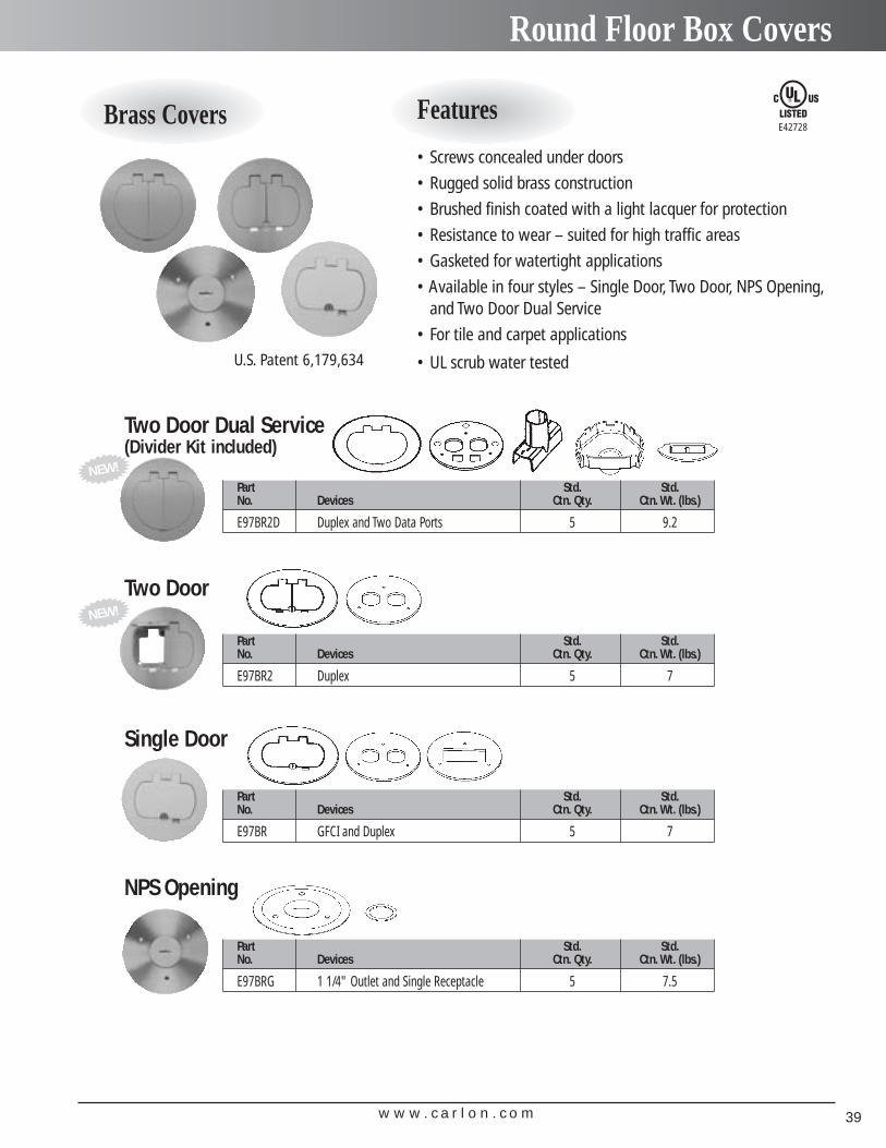
Round Floor Box Covers
Part Std. Std.No. Devices Ctn. Qty. Ctn. Wt. (lbs.)
E97BR2D Duplex and Two Data Ports 5 9.2
Two Door Dual Service(Divider Kit included)
Part Std. Std.No. Devices Ctn. Qty. Ctn. Wt. (lbs.)
E97BR2 Duplex 5 7
Two Door
Brass Covers Features
• Screws concealed under doors
• Rugged solid brass construction
• Brushed finish coated with a light lacquer for protection
• Resistance to wear – suited for high traffic areas
• Gasketed for watertight applications
• Available in four styles – Single Door, Two Door, NPS Opening,and Two Door Dual Service
• For tile and carpet applications
• UL scrub water tested
E42728
Part Std. Std.No. Devices Ctn. Qty. Ctn. Wt. (lbs.)
E97BR GFCI and Duplex 5 7
Single Door
Part Std. Std.No. Devices Ctn. Qty. Ctn. Wt. (lbs.)
E97BRG 1 1/4" Outlet and Single Receptacle 5 7.5
NPS Opening
NEW!
NEW!
U.S. Patent 6,179,634
w w w . c a r l o n . c o m40
Carlon Adjustable Residential Floor Boxes
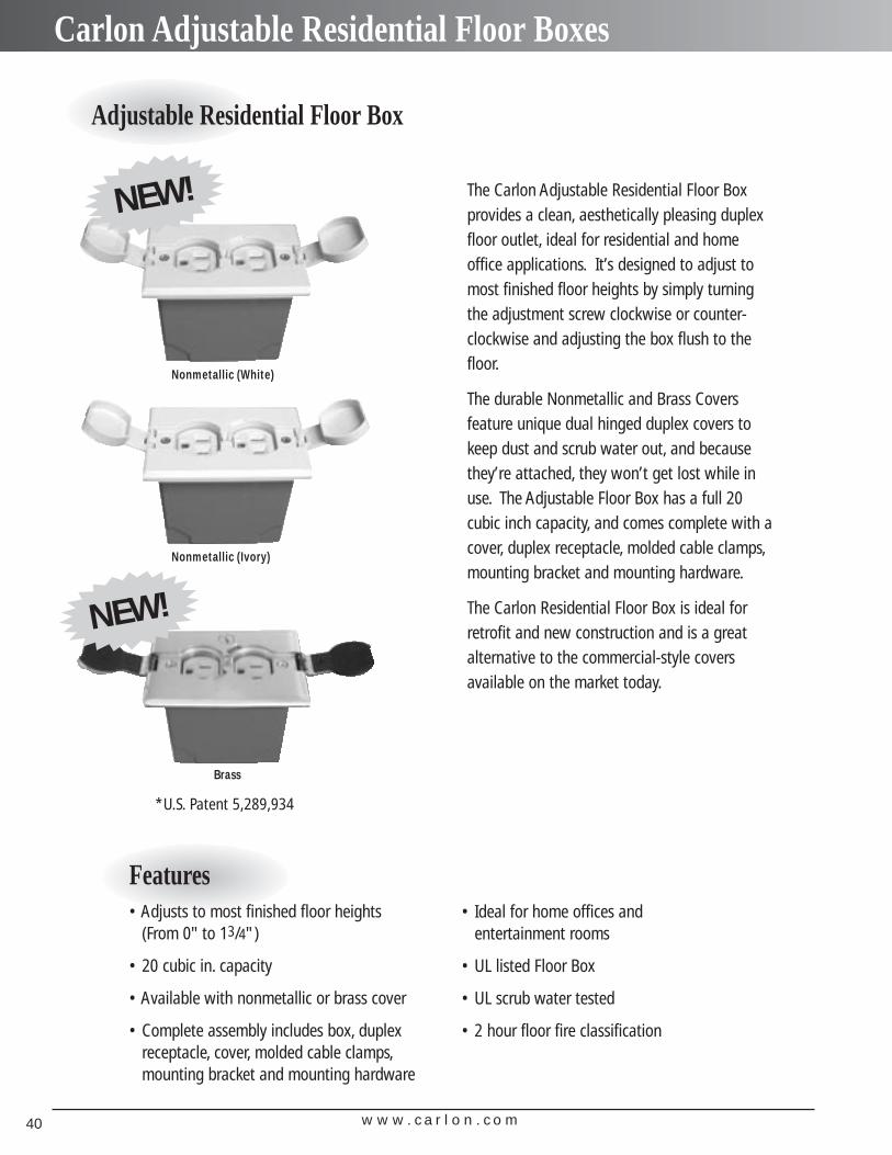
Adjustable Residential Floor Box
The Carlon Adjustable Residential Floor Boxprovides a clean, aesthetically pleasing duplexfloor outlet, ideal for residential and homeoffice applications. It’s designed to adjust tomost finished floor heights by simply turningthe adjustment screw clockwise or counter-clockwise and adjusting the box flush to thefloor.
The durable Nonmetallic and Brass Covers feature unique dual hinged duplex covers tokeep dust and scrub water out, and becausethey’re attached, they won’t get lost while inuse. The Adjustable Floor Box has a full 20cubic inch capacity, and comes complete with acover, duplex receptacle, molded cable clamps,mounting bracket and mounting hardware.
The Carlon Residential Floor Box is ideal forretrofit and new construction and is a greatalternative to the commercial-style covers available on the market today.
Nonmetallic (White)
Nonmetallic (Ivory)
Brass
NEW!
NEW!
Features• Adjusts to most finished floor heights
(From 0" to 13/4")
• 20 cubic in. capacity
• Available with nonmetallic or brass cover
• Complete assembly includes box, duplex receptacle, cover, molded cable clamps,mounting bracket and mounting hardware
• Ideal for home offices andentertainment rooms
• UL listed Floor Box
• UL scrub water tested
• 2 hour floor fire classification
*U.S. Patent 5,289,934
w w w . c a r l o n . c o m 41
Carlon Adjustable Residential Floor Boxes
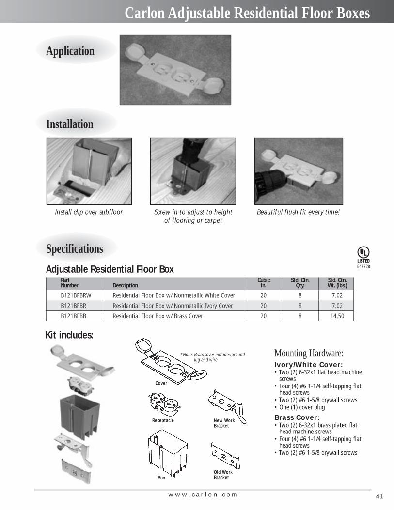
Application
Installation
Specifications
Cover
Receptacle
Box
New WorkBracket
Old WorkBracket
Screw in to adjust to heightof flooring or carpet
Beautiful flush fit every time!
Kit includes:
*Note: Brass cover includes groundlug and wire
Install clip over subfloor.
Adjustable Residential Floor BoxPart Cubic Std. Ctn. Std. Ctn.Number Description In. Qty. Wt. (lbs.)
B121BFBRW Residential Floor Box w/ Nonmetallic White Cover 20 8 7.02
B121BFBR Residential Floor Box w/ Nonmetallic Ivory Cover 20 8 7.02
B121BFBB Residential Floor Box w/ Brass Cover 20 8 14.50
E42728
Mounting Hardware:Ivory/White Cover:• Two (2) 6-32x1 flat head machine
screws• Four (4) #6 1-1/4 self-tapping flat
head screws• Two (2) #6 1-5/8 drywall screws• One (1) cover plug
Brass Cover:• Two (2) 6-32x1 brass plated flat
head machine screws• Four (4) #6 1-1/4 self-tapping flat
head screws• Two (2) #6 1-5/8 drywall screws

w w w . c a r l o n . c o m42
w w w . c a r l o n . c o m 43
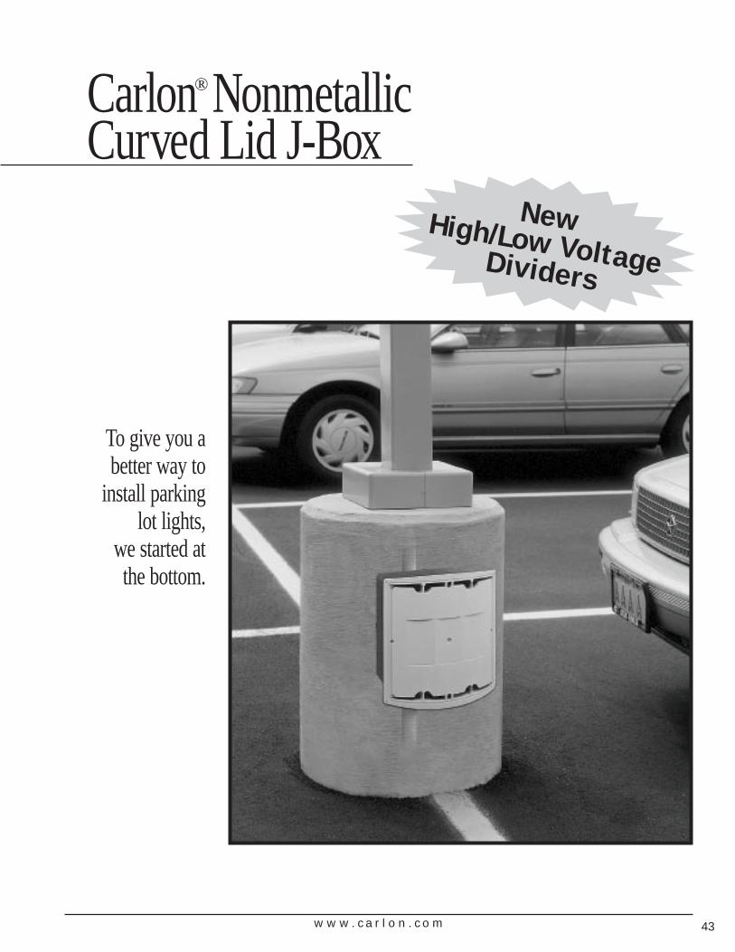
To give you a better way to
install parking lot lights,
we started at the bottom.
Carlon® NonmetallicCurved Lid J-Box
New High/Low VoltageDividers
w w w . c a r l o n . c o m44
Carlon® Nonmetallic Curved Lid J-Box
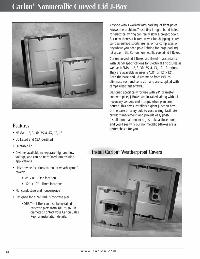
Anyone who’s worked with parking lot light polesknows the problem. Those tiny integral hand holesfor electrical wiring can really slow a project down.But now there’s a better answer for shopping centers,car dealerships, sports arenas, office complexes, oranywhere you need pole lighting for large parkinglot areas – the Carlon nonmetallic curved lid J-Boxes.
Carlon curved lid J-Boxes are listed in accordancewith UL 50 specifications for Electrical Enclosures aswell as NEMA 1, 2, 3, 3R, 3S, 4, 4X, 12, 13 ratings.They are available in sizes 8"x8" or 12"x12".Both the base and lid are made from PVC to eliminate rust and corrosion and are supplied withtamper-resistant screws.
Designed specifically for use with 24" diameter concrete piers, J-Boxes are installed, along with allnecessary conduit and fittings, when piers arepoured. This gives installers a giant junction box at the base of every pole to ease wiring, facilitatecircuit management, and provide easy post-installation maintenance. Just take a closer look,and you’ll see why our nonmetallic J-Boxes are abetter choice for you.
Features• NEMA 1, 2, 3, 3R, 3S, 4, 4X, 12, 13
• UL Listed and CSA Certified
• Paintable lid
• Dividers available to separate high and lowvoltage, and can be retrofitted into existingapplications
• Lids provide locations to mount weatherproofcovers:
▲ 8" x 8" - One location▲ 12" x 12" - Three locations
• Nonconductive and noncorrosive
• Designed for a 24" radius concrete pier
NOTE: The J-Box can also be installed inconcrete piers from 18" to 36" indiameter. Contact your Carlon SalesRep for installation details.
Install Carlon® Weatherproof Covers
w w w . c a r l o n . c o m 45
Installation and Wiring
Faster, easier wiring for greater productivity. Easy to Install
More flexibility, fewer home runs,and easier maintenance, too.
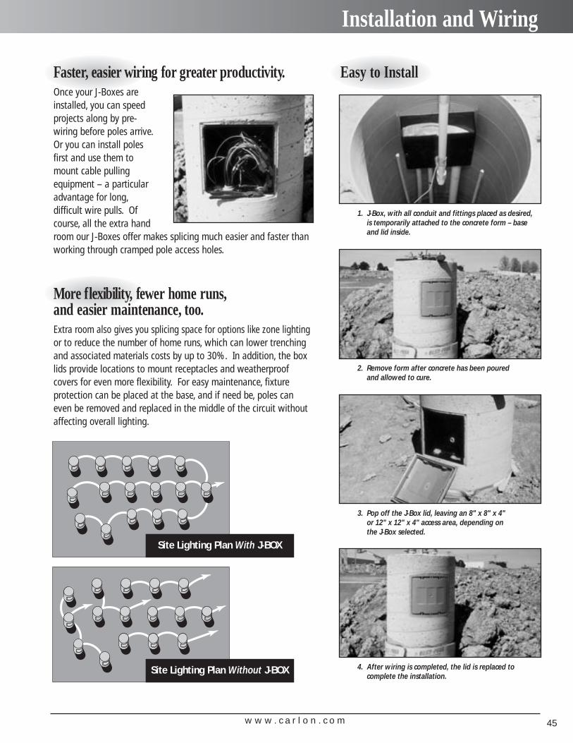
Once your J-Boxes areinstalled, you can speedprojects along by pre-wiring before poles arrive.Or you can install polesfirst and use them tomount cable pulling equipment – a particularadvantage for long,difficult wire pulls. Ofcourse, all the extra handroom our J-Boxes offer makes splicing much easier and faster thanworking through cramped pole access holes.
Extra room also gives you splicing space for options like zone lightingor to reduce the number of home runs, which can lower trenchingand associated materials costs by up to 30%. In addition, the boxlids provide locations to mount receptacles and weatherproof covers for even more flexibility. For easy maintenance, fixture protection can be placed at the base, and if need be, poles caneven be removed and replaced in the middle of the circuit withoutaffecting overall lighting.
1. J-Box, with all conduit and fittings placed as desired, is temporarily attached to the concrete form – baseand lid inside.
2. Remove form after concrete has been poured and allowed to cure.
3. Pop off the J-Box lid, leaving an 8" x 8" x 4" or 12" x 12" x 4" access area, depending on the J-Box selected.
4. After wiring is completed, the lid is replaced to complete the installation.
Site Lighting Plan Without J-BOX
Site Lighting Plan With J-BOX
w w w . c a r l o n . c o m46
Specifications & Accessories
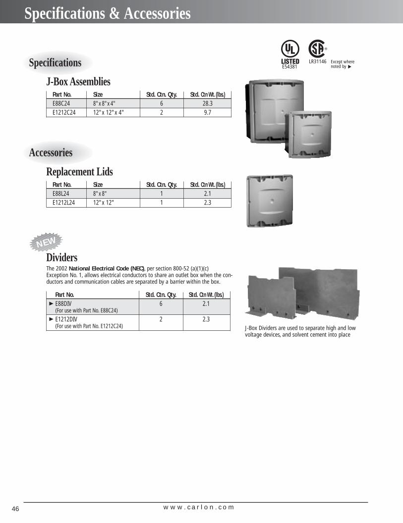
The 2002 National Electrical Code (NEC), per section 800-52 (a)(1)(c) Exception No. 1, allows electrical conductors to share an outlet box when the con-ductors and communication cables are separated by a barrier within the box.
Part No. Size Std. Ctn. Qty. Std. Ctn Wt. (lbs.)E88C24 8"x 8"x 4" 6 28.3E1212C24 12"x 12"x 4" 2 9.7
J-Box Assemblies
Part No. Size Std. Ctn. Qty. Std. Ctn Wt. (lbs.)E88L24 8"x 8" 1 2.1E1212L24 12"x 12" 1 2.3
Replacement Lids
Part No. Std. Ctn. Qty. Std. Ctn Wt. (lbs.)E88DIV 6 2.1(For use with Part No. E88C24)
E1212DIV 2 2.3(For use with Part No. E1212C24)
Dividers
J-Box Dividers are used to separate high and lowvoltage devices, and solvent cement into place
NEW
E54381LR31146Specifications
Accessories
▼▼
Except wherenoted by ▼

w w w . c a r l o n . c o m 47
InnovativeSolutions for
Outdoor Lighting
and ElectricalApplications
Carlon® Weatherproof Covers and Light Systems
w w w . c a r l o n . c o m48
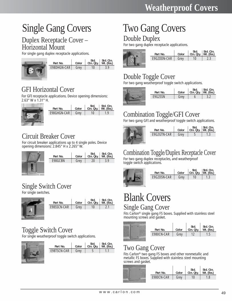
Weatherproof Covers
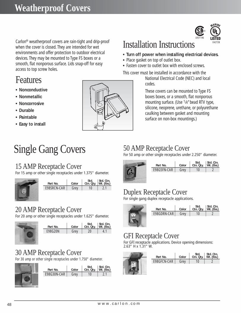
Single Gang Covers15 AMP Receptacle CoverFor 15 amp or other single receptacles under 1.375" diameter.
Std. Std. Ctn.Part No. Color Ctn. Qty. Wt. (lbs.)
E98SRCN-CAR Grey 10 2.1
30 AMP Receptacle CoverFor 30 amp or other single receptacles under 1.750" diameter.
Std. Std. Ctn.Part No. Color Ctn. Qty. Wt. (lbs.)
E98G30N-CAR Grey 10 2.1
50 AMP Receptacle CoverFor 50 amp or other single receptacles under 2.250" diameter.
Std. Std. Ctn.Part No. Color Ctn. Qty. Wt. (lbs.)
E98G5FN-CAR Grey 10 2
Duplex Receptacle CoverFor single gang duplex receptacle applications.
Std. Std. Ctn.Part No. Color Ctn. Qty. Wt. (lbs.)
E98GDRN-CAR Grey 10 2
GFI Receptacle CoverFor GFI receptacle applications. Device opening dimensions:2.63" H x 1.31" W.
Std. Std. Ctn.Part No. Color Ctn. Qty. Wt. (lbs.)
E98GFCN-CAR Grey 10 2
20 AMP Receptacle CoverFor 20 amp or other single receptacles under 1.625" diameter.
Std. Std. Ctn.Part No. Color Ctn. Qty. Wt. (lbs.)
E98G20N Grey 20 4.1
Carlon® weatherproof covers are rain-tight and drip-proofwhen the cover is closed. They are intended for wet environments and offer protection to outdoor electricaldevices. They may be mounted to Type FS boxes or asmooth, flat nonporous surface. Lids snap-off for easy access to top screw holes.
Features• Nonconductive• Nonmetallic• Noncorrosive• Durable• Paintable• Easy to install
Installation Instructions• Turn off power when installing electrical devices.• Place gasket on top of outlet box.• Fasten cover to outlet box with enclosed screws.
This cover must be installed in accordance with theNational Electrical Code (NEC) and localcodes.
These covers can be mounted to Type FSboxes boxes, or a smooth, flat nonporousmounting surface. (Use 1/4"bead RTV type,silicone, neoprene, urethane, or polyurethanecaulking between gasket and mounting surface on non-box mountings.)
E42728
LR31146
w w w . c a r l o n . c o m 49
Weatherproof Covers
Two Gang CoversDouble DuplexFor two gang duplex receptacle applications.
Std. Std. Ctn.Part No. Color Ctn. Qty. Wt. (lbs.)
E9G2DDN-CAR Grey 10 2.3
Combination Toggle/GFI CoverFor two gang GFI and weatherproof toggle switch applications.
Std. Std. Ctn.Part No. Color Ctn. Qty. Wt. (lbs.)
E9G2GTN-CAR Grey 5 1.3
Combination Toggle/Duplex Receptacle CoverFor two gang duplex receptacles, and weatherproof toggle switch applications.
Std. Std. Ctn.Part No. Color Ctn. Qty. Wt. (lbs.)
E9G2DSN-CAR Grey 10 1.3
Double Toggle CoverFor two gang weatherproof toggle switch applications.
Std. Std. Ctn.Part No. Color Ctn. Qty. Wt. (lbs.)
E9G2SSN Grey 6 3.2
Single Gang CoversDuplex Receptacle Cover –Horizontal MountFor single gang duplex receptacle applications.
Std. Std. Ctn.Part No. Color Ctn. Qty. Wt. (lbs.)
E98DHGN-CAR Grey 10 3.9
Circuit Breaker CoverFor circuit breaker applications up to 4 single poles. Deviceopening dimensions: 2.845"H x 2.265"W.
Std. Std. Ctn.Part No. Color Ctn. Qty. Wt. (lbs.)
E98GCBN Grey 20 3.9
Single Switch CoverFor single switches.
Std. Std. Ctn.Part No. Color Ctn. Qty. Wt. (lbs.)
E98SSCN-CAR Grey 10 2.1
Toggle Switch CoverFor single weatherproof toggle switch applications.
Std. Std. Ctn.Part No. Color Ctn. Qty. Wt. (lbs.)
E98TSCN-CAR Grey 5 1.1
GFI Horizontal CoverFor GFI receptacle applications. Device opening dimensions:2.63"W x 1.31"H.
Std. Std. Ctn.Part No. Color Ctn. Qty. Wt. (lbs.)
E98GHGN-CAR Grey 10 1.9
Blank CoversSingle Gang CoverFits Carlon® single gang FS boxes. Supplied with stainless steelmounting screws and gasket.
Std. Std. Ctn.Part No. Color Ctn. Qty. Wt. (lbs.)
E980CN-CAR Grey 12 1.5
Two Gang CoverFits Carlon® two gang FS boxes and other nonmetallic andmetallic FS boxes. Supplied with stainless steel mountingscrews and gasket.
Std. Std. Ctn.Part No. Color Ctn. Qty. Wt. (lbs.)
E980CN-CAR Grey 10 1.8
w w w . c a r l o n . c o m50
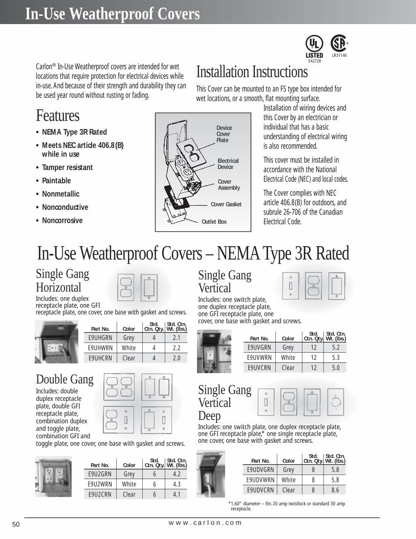
In-Use Weatherproof Covers
Carlon® In-Use Weatherproof covers are intended for wetlocations that require protection for electrical devices whilein-use. And because of their strength and durability they canbe used year round without rusting or fading.
Features• NEMA Type 3R Rated
• Meets NEC article 406.8(B) while in use
• Tamper resistant
• Paintable
• Nonmetallic
• Nonconductive
• Noncorrosive
Installation InstructionsThis Cover can be mounted to an FS type box intended forwet locations, or a smooth, flat mounting surface.
Installation of wiring devices and this Cover by an electrician or individual that has a basic understanding of electrical wiring is also recommended.
This cover must be installed in accordance with the NationalElectrical Code (NEC) and local codes.
The Cover complies with NECarticle 406.8(B) for outdoors, andsubrule 26-706 of the CanadianElectrical Code.
DeviceCoverPlate
ElectricalDevice
CoverAssembly
Cover Gasket
Outlet Box
In-Use Weatherproof Covers – NEMA Type 3R RatedSingle Gang HorizontalIncludes: one duplex receptacle plate, one GFI receptacle plate, one cover, one base with gasket and screws.
Std. Std. Ctn.Part No. Color Ctn. Qty. Wt. (lbs.)
E9UHGRN Grey 4 2.1
E9UHWRN White 4 2.2
E9UHCRN Clear 4 2.0
Double GangIncludes: double duplex receptacle plate, double GFI receptacle plate,combination duplex and toggle plate,combination GFI and toggle plate, one cover, one base with gasket and screws.
Std. Std. Ctn.Part No. Color Ctn. Qty. Wt. (lbs.)
E9U2GRN Grey 6 4.2
E9U2WRN White 6 4.3
E9U2CRN Clear 6 4.1
Single Gang VerticalIncludes: one switch plate,one duplex receptacle plate,one GFI receptacle plate, one cover, one base with gasket and screws.
Std. Std. Ctn.Part No. Color Ctn. Qty. Wt. (lbs.)
E9UVGRN Grey 12 5.2
E9UVWRN White 12 5.3
E9UVCRN Clear 12 5.0
Single Gang Vertical DeepIncludes: one switch plate, one duplex receptacle plate,one GFI receptacle plate,* one single receptacle plate,one cover, one base with gasket and screws.
Std. Std. Ctn.Part No. Color Ctn. Qty. Wt. (lbs.)
E9UDVGRN Grey 8 5.8
E9UDVWRN White 8 5.8
E9UDVCRN Clear 8 8.6
*1.60" diameter – fits 20 amp twistlock or standard 30 ampreceptacle.
E42728LR31146
w w w . c a r l o n . c o m 51
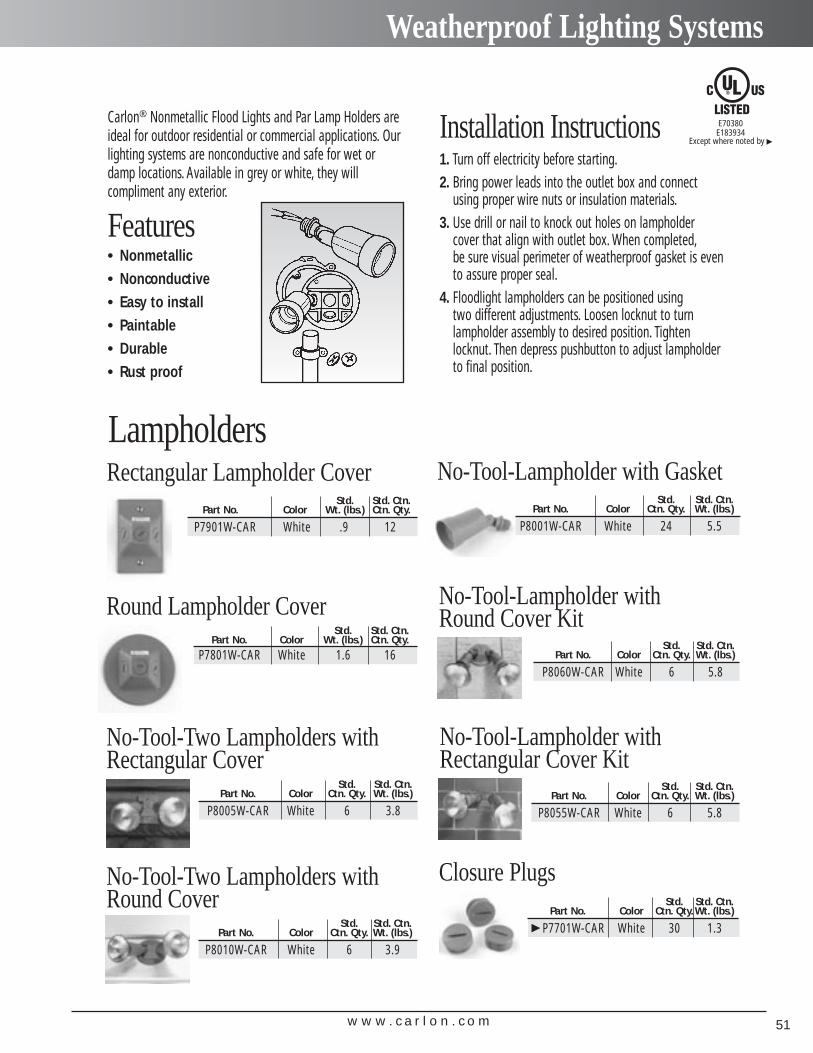
Weatherproof Lighting Systems
LampholdersRectangular Lampholder Cover
Std. Std. Ctn.Part No. Color Wt. (lbs.) Ctn. Qty.
P7901W-CAR White .9 12
Round Lampholder CoverStd. Std. Ctn.
Part No. Color Wt. (lbs.) Ctn. Qty.
P7801W-CAR White 1.6 16
Carlon® Nonmetallic Flood Lights and Par Lamp Holders areideal for outdoor residential or commercial applications. Ourlighting systems are nonconductive and safe for wet ordamp locations. Available in grey or white, they will compliment any exterior.
Features• Nonmetallic• Nonconductive• Easy to install• Paintable• Durable• Rust proof
Installation Instructions1. Turn off electricity before starting.2. Bring power leads into the outlet box and connect
using proper wire nuts or insulation materials.3. Use drill or nail to knock out holes on lampholder
cover that align with outlet box. When completed,be sure visual perimeter of weatherproof gasket is evento assure proper seal.
4. Floodlight lampholders can be positioned using two different adjustments. Loosen locknut to turn lampholder assembly to desired position. Tighten locknut. Then depress pushbutton to adjust lampholder to final position.
No-Tool-Lampholder with GasketStd. Std. Ctn.
Part No. Color Ctn. Qty. Wt. (lbs.)
P8001W-CAR White 24 5.5
No-Tool-Two Lampholders withRectangular Cover
Std. Std. Ctn.Part No. Color Ctn. Qty. Wt. (lbs.)
P8005W-CAR White 6 3.8
No-Tool-Lampholder with Round Cover Kit
Std. Std. Ctn.Part No. Color Ctn. Qty. Wt. (lbs.)
P8060W-CAR White 6 5.8
No-Tool-Lampholder withRectangular Cover Kit
Std. Std. Ctn.Part No. Color Ctn. Qty. Wt. (lbs.)
P8055W-CAR White 6 5.8
No-Tool-Two Lampholders withRound Cover
Std. Std. Ctn.Part No. Color Ctn. Qty. Wt. (lbs.)
P8010W-CAR White 6 3.9
Closure PlugsStd. Std. Ctn.
Part No. Color Ctn. Qty.Wt. (lbs.)
� P7701W-CAR White 30 1.3
E70380E183934
Except where noted by �
w w w . c a r l o n . c o m52
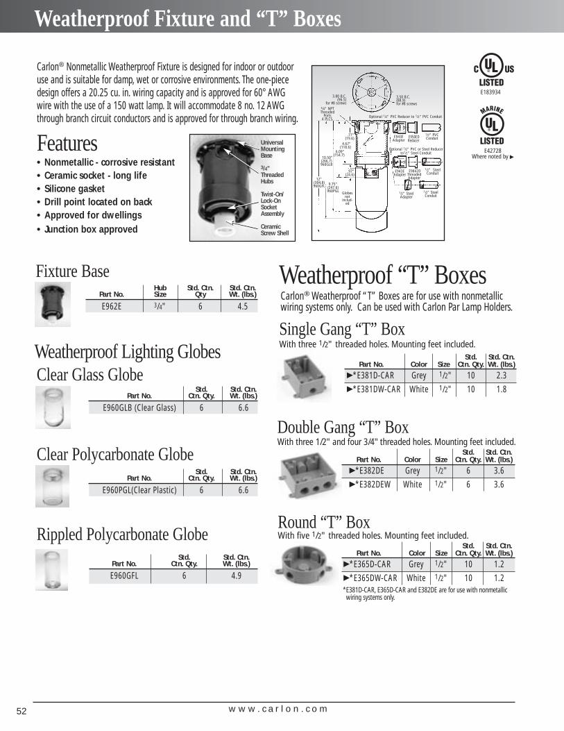
Weatherproof Fixture and “T” Boxes
Carlon® Nonmetallic Weatherproof Fixture is designed for indoor or outdooruse and is suitable for damp, wet or corrosive environments. The one-piecedesign offers a 20.25 cu. in. wiring capacity and is approved for 60° AWGwire with the use of a 150 watt lamp. It will accommodate 8 no. 12 AWGthrough branch circuit conductors and is approved for through branch wiring.
Features• Nonmetallic - corrosive resistant• Ceramic socket - long life• Silicone gasket• Drill point located on back• Approved for dwellings• Junction box approved
3.80 B.C.(96.5)
for #8 screws
E943EAdapter
3/4" NPTThreaded
Ports4 PLCS.
Optional 1/2" PVC Reducer to 1/2" PVC Conduit
Optional 1/2" PVC or Steel Reducer to1/2" Steel Conduit
E950EDReducer
E9842DThreadedAdapter
E943EAdapter
1/2" SteelAdapter
1/2" SteelConduit
1/2" SteelConduit
1/2" PVCConduit
3.50 B.C.(88.9)for #8 screws
.77"(19.6)
.97"(24.6)
10.50"(266.7)960GLB
12"(304.8)960GFL 9.75"
(247.6)960PGL Globes
notinclud-
ed
6.09"(154.7)
4.67"(118.6)
Universal Mounting Base
3/4" Threaded Hubs
Twist-On/Lock-On Socket Assembly
Ceramic Screw Shell
Weatherproof Lighting Globes
Fixture BaseHub Std. Ctn. Std. Ctn.
Part No. Size Qty Wt. (lbs.)
E962E 3/4" 6 4.5
Rippled Polycarbonate GlobeStd. Std. Ctn.
Part No. Ctn. Qty. Wt. (lbs.)
E960GFL 6 4.9
Clear Glass GlobeStd. Std. Ctn.
Part No. Ctn. Qty. Wt. (lbs.)
E960GLB (Clear Glass) 6 6.6
Std. Std. Ctn.Part No. Ctn. Qty. Wt. (lbs.)
E960PGL(Clear Plastic) 6 6.6
Clear Polycarbonate Globe
Carlon® Weatherproof “T” Boxes are for use with nonmetallicwiring systems only. Can be used with Carlon Par Lamp Holders.
Weatherproof “T” Boxes
Single Gang “T” BoxWith three 1/2" threaded holes. Mounting feet included.
Std. Std. Ctn.Part No. Color Size Ctn. Qty. Wt. (lbs.)
�*E381D-CAR Grey 1/2" 10 2.3�*E381DW-CAR White 1/2" 10 1.8
Std. Std. Ctn.Part No. Color Size Ctn. Qty. Wt. (lbs.)
�*E382DE Grey 1/2" 6 3.6�*E382DEW White 1/2" 6 3.6
Std. Std. Ctn.Part No. Color Size Ctn. Qty. Wt. (lbs.)
�*E365D-CAR Grey 1/2" 10 1.2�*E365DW-CAR White 1/2" 10 1.2
Double Gang “T” BoxWith three 1/2" and four 3/4"threaded holes. Mounting feet included.
Round “T” BoxWith five 1/2" threaded holes. Mounting feet included.
*E381D-CAR, E365D-CAR and E382DE are for use with nonmetallic wiring systems only.
E183934
E42728Where noted by �

w w w . c a r l o n . c o m 53
Tough on the job,easy on you.
Carlon® Wire Safe®
Wireway And Wiring Trough
w w w . c a r l o n . c o m54
Introduction
Easy To Cut And Assemble.Wireway and trough can be cut easily andcleanly with either a hacksaw or fine toothsaw to make field fabrication a snap. And it’sequally easy to couple components eitherwith Carlon primer and PVC cement or nonmetallic push rivets.
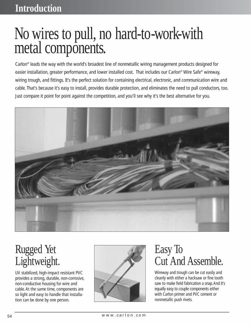
No wires to pull, no hard-to-work-withmetal components. Carlon® leads the way with the world’s broadest line of nonmetallic wiring management products designed for
easier installation, greater performance, and lower installed cost. That includes our Carlon® Wire Safe® wireway,
wiring trough, and fittings. It’s the perfect solution for containing electrical, electronic, and communication wire and
cable. That’s because it’s easy to install, provides durable protection, and eliminates the need to pull conductors, too.
Just compare it point for point against the competition, and you’ll see why it’s the best alternative for you.
Rugged Yet Lightweight.UV stabilized, high-impact resistant PVCprovides a strong, durable, non-corrosive,non-conductive housing for wire andcable. At the same time, components areso light and easy to handle that installa-tion can be done by one person.
w w w . c a r l o n . c o m 55
Introduction
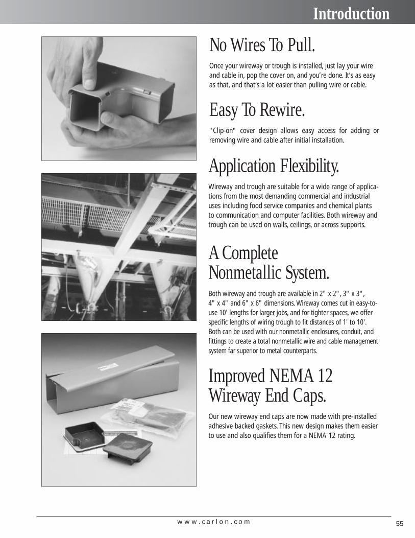
Improved NEMA 12Wireway End Caps.
No Wires To Pull.Once your wireway or trough is installed, just lay your wireand cable in, pop the cover on, and you’re done. It’s as easyas that, and that’s a lot easier than pulling wire or cable.
Easy To Rewire."Clip-on" cover design allows easy access for adding orremoving wire and cable after initial installation.
Application Flexibility.Wireway and trough are suitable for a wide range of applica-tions from the most demanding commercial and industrialuses including food service companies and chemical plantsto communication and computer facilities. Both wireway andtrough can be used on walls, ceilings, or across supports.
Our new wireway end caps are now made with pre-installedadhesive backed gaskets. This new design makes them easierto use and also qualifies them for a NEMA 12 rating.
A Complete Nonmetallic System.Both wireway and trough are available in 2" x 2", 3" x 3",4" x 4" and 6" x 6" dimensions. Wireway comes cut in easy-to-use 10' lengths for larger jobs, and for tighter spaces, we offerspecific lengths of wiring trough to fit distances of 1' to 10'.Both can be used with our nonmetallic enclosures, conduit, andfittings to create a total nonmetallic wire and cable managementsystem far superior to metal counterparts.
w w w . c a r l o n . c o m56
Carlon® Wiresafe® Wireway
Carlon® Wiresafe® WirewayOutside Std. Wt.
Part Nominal Ctn. (lbs.)No. Dimensions Length Qty. per 10'
17011 2 x 2 10' 1 4.7
17013 3 x 3 10' 1 11.2
17015 4 x 4 10' 1 11.2
17017 6 x 6 10' 1 21.4
Carlon® Wiresafe® Wiring Trough
Except wherenoted by ▼
E151021
All wiring trough is made to order and is supplied with a pair of end caps.
Part Outside Nominal Standard Wt./Lbs.Number Dimensions Carton Qty. Each
12" Trough18111 2 x 2 1 0.618113 3 x 3 1 1.018115 4 x 4 1 1.418117 6 x 6 1 3.1
24" Trough18211 2 x 2 1 1.118213 3 x 3 1 1.818215 4 x 4 1 2.618217 6 x 6 1 5.3
36" Trough18311 2 x 2 1 1.518313 3 x 3 1 2.618315 4 x 4 1 3.718317 6 x 6 1 7.4
48" Trough18411 2 x 2 1 2.018413 3 x 3 1 3.318415 4 x 4 1 4.818417 6 x 6 1 9.6
60" Trough18511 2 x 2 1 2.518513 3 x 3 1 4.118515 4 x 4 1 5.918517 6 x 6 1 11.7
72" Trough18611 2 x 2 1 2.918613 3 x 3 1 4.918615 4 x 4 1 7.118617 6 x 6 1 13.8
120" Trough18011 2 x 2 1 4.818013 3 x 3 1 8.118015 4 x 4 1 11.618017 6 x 6 1 22.4
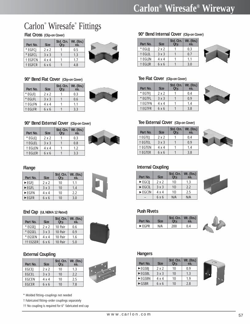
w w w . c a r l o n . c o m 57
Carlon® Wiresafe® Wireway
Carlon® Wiresafe® FittingsStd. Ctn. Wt. (lbs.)
Part No. Size Qty. ea.* EGFCJ 2 x 2 1 0.5* EGFCL 3 x 3 1 1.3† EGFCN 4 x 4 1 1.7† EGFCR 6 x 6 1 4.8
Flat Cross (Clip-on Cover)
Std. Ctn. Wt. (lbs.)Part No. Size Qty. ea.* EGLIJ 2 x 2 1 0.3† EGLIL 3 x 3 1 0.7† EGLIN 4 x 4 1 1.1† EGLIR 6 x 6 1 3.0
90° Bend Internal Cover (Clip-on Cover)
Std. Ctn. Wt. (lbs.)Part No. Size Qty. ea.
* EGLFJ 2 x 2 1 0.3* EGLFL 3 x 3 1 0.6† EGLFN 4 x 4 1 1.1† EGLFR 6 x 6 1 3.3
90° Bend Flat Cover (Clip-on Cover)
Std. Ctn. Wt. (lbs.)Part No. Size Qty. ea.* EGTFJ 2 x 2 1 0.4* EGTFL 3 x 3 1 0.9† EGTFN 4 x 4 1 1.4† EGTFR 6 x 6 1 3.8
Tee Flat Cover (Clip-on Cover)
Std. Ctn. Wt. (lbs.)Part No. Size Qty. ea.* EGLEJ 2 x 2 1 0.3† EGLEL 3 x 3 1 0.8† EGLEN 4 x 4 1 1.2† EGLER 6 x 6 1 3.3
90° Bend External Cover (Clip-on Cover)
Std. Ctn. Wt. (lbs.)Part No. Size Qty. ea.
† EGTEJ 2 x 2 1 0.4† EGTEL 3 x 3 1 0.9† EGTEN 4 x 4 1 1.4† EGTER 6 x 6 1 3.8
Tee External Cover (Clip-on Cover)
Std. Ctn. Wt. (lbs.)Part No. Size Qty. ea.
EGFJ 2 x 2 10 1.1EGFL 3 x 3 10 1.4EGFN 4 x 4 10 2.2EGFR 6 x 6 10 3.0
FlangeStd. Ctn. Wt. (lbs.)
Part No. Size Qty. ea.EGCIJ 2 x 2 1O 1.3EGCIL 3 x 3 1O 2.2EGCIN 4 x 4 1O 2.5
– 6 x 6 N/A N/A
Internal Coupling
Std. Ctn. Wt. (lbs.)Part No. Size Qty. ea.* EGSEJ 2 x 2 10 Pair 0.6* EGSEL 3 x 3 10 Pair 0.9* EGSEN 4 x 4 10 Pair 1.6†† EGSER 6 x 6 10 Pair 5.0
End Cap (UL NEMA 12 Rated)
Std. Ctn. Wt. (lbs.)Part No. Size Qty. ea.
EGPR N/A 200 0.4
Push Rivets
Std. Ctn. Wt. (lbs.)Part No. Size Qty. ea.EGCEJ 2 x 2 10 1.3EGCEL 3 x 3 10 2.2EGCEN 4 x 4 10 2.5EGCER 6 x 6 10 7.8
External CouplingStd. Ctn. Wt. (lbs.)
Part No. Size Qty. ea.EGSBJ 2 x 2 10 0.9EGSBL 3 x 3 10 1.3EGSBN 4 x 4 10 1.9GSBR 6 x 6 10 2.8
Hangers
▼▼
▼▼
▼▼
▼▼
* Molded fitting–couplings not needed
† Fabricated fitting–order couplings separately
†† No coupling is required for 6" fabricated end cap
▼▼
▼▼

w w w . c a r l o n . c o m58
Installation
Installation InstructionsDescription. Carlon Wire Safe wireway and wiring troughs are manufactured from extruded PVC. The standard color isgray. The wireway consists of a base channel that is formed to receive a “clip-on” cover. Wiring troughs include a pair ofready-to-install end caps.Cover Installation and Removal. The cover can be installed by exerting hand pressure along its front face in such amanner as to engage and clip projections on the side walls of the base channel. The cover can be removed by inserting a tool(i.e., a screwdriver shaft) into one end of the wireway enclosure and exerting pressure against the underside of the cover,which is then “peeled off” from the base.Wireway Fittings. Fittings enable the wireway to be positioned around corners and enable tees and crosses to be createdwithout detracting from the protective characteristics. Interconnecting pieces can be assembled using couplings and rivets orcement as necessary.Molded fittings do not require couplings since they fit on the exterior of the wireway. However, primer and solvent cement areneeded. See cementing instructions.Fabricated fittings do require internal or external couplings, and these must be ordered separately. To install fittings, a 9/32"diameter hole should be drilled in the wireway to match the external coupling hole. A push rivet should be used to connect thetwo pieces. To connect an internal coupling to the inside of a fitting, use Carlon Quick-Set Clear Cement.Applications. These systems are designed for use in commercial and industrial areas. They may be used for the contain-ment of electrical wiring/cables for power and lighting circuits and also communication and computer facilities. They are suit-able for mounting on the surface of walls or ceilings or suspended across suitably positioned supports. Ambient temperatures should not exceed 1400 F.
Engineering SpecificationsCode Approvals. Carlon's Wire Safe Wireway and Wiring Trough is recognized by the current National Electrical Code, Article 378, for nonmetallic wireways.It is UL Listed for electrical wiring up to 600 volts. UL File Numbers: UL E151021.Specification for Carlon Wire Safe Wireway and Wiring Trough.The wireway and wiring troughs shall be Carlon Wire Safe Wireway and Wiring Trough.The Carlon Wire Safe Wireway and Wiring Trough shall provide protection for electrical, low voltage, data and communication wiring or cables.The Carlon Wire Safe Wireway and Wiring Trough shall be listed and installed per the NEC Article 378 for nonmetallic wireways.The Carlon Wire Safe Wireway and Wiring Trough shall be manufactured from gray precision extruded Polyvinyl Chloride (PVC) meeting UL 94 V-Orequirements and shall be suitable for field painting.The Carlon Wire Safe Wireway and Wiring Trough shall include base, cover, fittings, etc.The Carlon Wire Safe Wireway and Wiring Trough shall provide all fittings required to form a complete, integrated surface raceway system.End caps shall be gasketed and shall have a NEMA Type 12 rating.The Carlon Wire Safe Wireway and Wiring Trough shall provide raceway with the following cross sectional areas:
1. 2 x 2 - 3.165 in.2 (20.4 cm2 ) 3. 4 x 4 - 13.694 in.2 (88 cm2 )2. 3 x 3 - 7.378 in.2 (47 cm2 ) 4. 6 x 6 - 31.871 in.2 (205 cm2 )
Fittings. Internal and external elbow shall be a fitting cover that snaps onto the main base. Flat elbows and flat tees shall be a fitting cover that snaps on to the main base. End caps shall be gasketed and NEMA Type 12 rated.Installation. Install in accordance with the manufacturer’s instructions, NFPA 70 and NECA standard.Install base, cover, fittings, accessories, etc., as necessary for a complete system.
Installation.1. Mark the surface upon which the wireway is to be mounted.2. Measure, run, and identify position of fittings.3. Remove cover from wireway, starting at one end, with a peeling
action (use of a screwdriver or similar lever is recommended).4. Drill mounting holes through base at 60" centers maximum. Two
rows of mounting holes should be drilled, adjacent to each wall ofthe wireway in order to evenly distribute the load.
5. The holes in the wireway should be drilled oversize to allow forexpansion. Washers should be mounted under the head of themounting device, which should not be tightened to its full extent.
6. Mount the wireway using screws or bolts.7. Affix the wireway cover by aligning it to the wireway base and
then pressing it into its engaged position, starting at one end.8. The cover should be made to overlap the base joint in order to
improve rigidity of the joint.
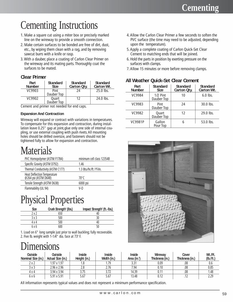
w w w . c a r l o n . c o m 59
Cementing
Cementing Instructions1. Make a square cut using a miter box or precisely marked
line on the wireway to provide a smooth connection.2. Make certain surfaces to be bonded are free of dirt, dust,
etc., by wiping them clean with a rag, and by removingsawcut burrs with a knife or rasp.
3. With a dauber, place a coating of Carlon Clear Primer onthe wireway and its mating parts. Thoroughly coat the surfaces to be mated.
4. Allow the Carlon Clear Primer a few seconds to soften thePVC surface (the time may need to be adjusted, dependingupon the temperature).
5. Apply a complete coating of Carlon Quick-Set ClearCement to matching ends that will be joined.
6. Hold the parts in position by exerting pressure on the surfaces with clamps.
7. Allow 15 minutes or more before removing clamps.
Part Standard Standard StandardNumber Size Carton Qty. Carton Wt.VC9984 1/2 Pint 10 6.0 lbs.
Dauber TopVC9983 Pint 24 30.0 lbs.
Dauber TopVC9982 Quart 12 29.0 lbs.
Dauber TopVC9981P Gallon 6 53.0 lbs.
Pour Top
PVC Homopolymer (ASTM F1784) minimum cell class 12354BSpecific Gravity (ASTM D792) 1.46Thermal Conductivity (ASTM C177) 1.3 Btu/hr./ft.2/0F/in.Heat Deflection Temperature@264 psi (ASTM D648) 700 CTensile Strength (ASTM D638) 6000 psiFlammability (UL 94) V-O
DimensionsOutside Outside Inside Inside Inside Wireway Cover Wt./Ft.
Nominal Size (in.) Actual Size (in.) Height (in.) Width (in.) Area (in.2) Thickness (in.) Thickness (in.) (lb./ft.)2 x 2 1.97 x 1.97 1.8 1.79 3.31 0.09 .08 0.63 x 3 2.96 x 2.96 2.8 2.76 7.94 0.10 .08 0.854 x 4 3.94 x 3.94 3.75 3.72 14.39 0.11 .08 1.486 x 6 5.91 x 5.91 5.67 5.67 13.48 0.12 .12 2.29
Size Crush Strength1 (lbs.) Impact Strength2 (ft.- lbs.)2 x 2 650 403 x 3 500 304 x 4 500 406 x 6 600 50
Physical Properties
1. Load on 6" long sample just prior to wall buckling; fully recoverable.2. Five lb. weight with 1-1/4" dia. face at 730 F.
All information represents typical values and does not represent a minimum performance specification.
All Weather Quick-Set Clear CementPart Standard Standard StandardNumber Size Carton Qty. Carton Wt.VC9903 Pint 24 25.0 lbs.
Dauber TopVC9902 Quart 12 24.0 lbs.
Dauber TopCement and primer not needed for end caps.
Clear Primer
Materials
Expansion And Contraction
Wireway will expand or contract with variations in temperatures.To compensate for this expansion and contraction, during instal-lation leave 0.25" gap at joint,glue only one side of internal cou-pling, or use external coupling with push rivets. All mountingholes should be drilled oversize, and fasteners should not be tightened fully to allow for expansion and contraction.
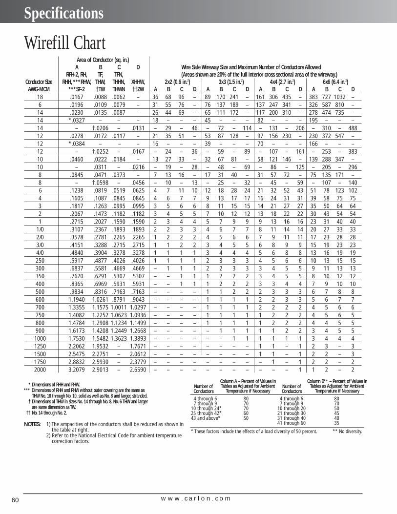
w w w . c a r l o n . c o m60
Specifications
Area of Conductor (sq. in.)A B C D Wire Safe Wireway Size and Maximum Number of Conductors Allowed
RFH-2, RH, TF, TFN, (Areas shown are 20% of the full interior cross sectional area of the wireway.)Conductor Size RHH, ***RHW, THW, THHN, XHHW, 2x2 (0.6 in.2) 3x3 (1.5 in.2) 4x4 (2.7 in.2) 6x6 (6.4 in.2)AWG-MCM ***SF-2 †TW THWN ††ZW A B C D A B C D A B C D A B C D
18 .0167 .0088 .0062 – 36 68 96 – 89 170 241 – 161 306 435 – 383 727 1032 –6 .0196 .0109 .0079 – 31 55 76 – 76 137 189 – 137 247 341 – 326 587 810 –14 .0230 .0135 .0087 – 26 44 69 – 65 111 172 – 117 200 310 – 278 474 735 –14 *.0327 – – – 18 – – – 45 – – – 82 – – – 195 – – –14 – †.0206 – .0131 – 29 – 46 – 72 – 114 – 131 – 206 – 310 – 48812 .0278 .0172 .0117 – 21 35 51 – 53 87 128 – 97 156 230 – 230 372 547 –12 *.0384 – – – 16 – – – 39 – – – 70 – – – 166 – – –12 – †.0252 – .0167 – 24 – 36 – 59 – 89 – 107 – 161 – 253 – 38310 .0460 .0222 .0184 – 13 27 33 – 32 67 81 – 58 121 146 – 139 288 347 –10 – .0311 – .0216 – 19 – 28 – 48 – 69 – 86 – 125 – 205 – 2968 .0845 .0471 .0373 – 7 13 16 – 17 31 40 – 31 57 72 – 75 135 171 –8 – †.0598 – .0456 – 10 – 13 – 25 – 32 – 45 – 59 – 107 – 1406 .1238 .0819 .0519 .0625 4 7 11 10 12 18 28 24 21 32 52 43 51 78 123 1024 .1605 .1087 .0845 .0845 4 6 7 7 9 13 17 17 16 24 31 31 39 58 75 753 .1817 .1263 .0995 .0995 3 5 6 6 8 11 15 15 14 21 27 27 35 50 64 642 .2067 .1473 .1182 .1182 3 4 5 5 7 10 12 12 13 18 22 22 30 43 54 541 .2715 .2027 .1590 .1590 2 3 4 4 5 7 9 9 9 13 16 16 23 31 40 40
1/0 .3107 .2367 .1893 .1893 2 2 3 3 4 6 7 7 8 11 14 14 20 27 33 332/0 .3578 .2781 .2265 .2265 1 2 2 2 4 5 6 6 7 9 11 11 17 23 28 283/0 .4151 .3288 .2715 .2715 1 1 2 2 3 4 5 5 6 8 9 9 15 19 23 234/0 .4840 .3904 .3278 .3278 1 1 1 1 3 4 4 4 5 6 8 8 13 16 19 19250 .5917 .4877 .4026 .4026 1 1 1 1 2 3 3 3 4 5 6 6 10 13 15 15300 .6837 .5581 .4669 .4669 – 1 1 1 2 2 3 3 3 4 5 5 9 11 13 13350 .7620 .6291 .5307 .5307 – – 1 1 1 2 2 2 3 4 5 5 8 10 12 12400 .8365 .6969 .5931 .5931 – – 1 1 1 2 2 2 3 3 4 4 7 9 10 10500 .9834 .8316 .7163 .7163 – – – – 1 1 2 2 2 3 3 3 6 7 8 8600 1.1940 1.0261 .8791 .9043 – – – – 1 1 1 1 2 2 3 3 5 6 7 7700 1.3355 1.1575 1.0011 1.0297 – – – – 1 1 1 1 2 2 2 2 4 5 6 6750 1.4082 1.2252 1.0623 1.0936 – – – – 1 1 1 1 1 2 2 2 4 5 6 5800 1.4784 1.2908 1.1234 1.1499 – – – – 1 1 1 1 1 2 2 2 4 4 5 5900 1.6173 1.4208 1.2449 1.2668 – – – – – 1 1 1 1 1 2 2 3 4 5 51000 1.7530 1.5482 1.3623 1.3893 – – – – – – 1 1 1 1 1 1 3 4 4 41250 2.2062 1.9532 – 1.7671 – – – – – – – – 1 1 – 1 2 3 – 31500 2.5475 2.2751 – 2.0612 – – – – – – – – 1 1 – 1 2 2 – 31750 2.8832 2.5930 – 2.3779 – – – – – – – – – 1 – 1 2 2 – 22000 3.2079 2.9013 – 2.6590 – – – – – – – – – – – 1 1 2 – 2
* Dimensions of RHH and RHW.*** Dimensions of RHH and RHW without outer covering are the same as
THW No. 18 through No. 10, solid as well as No. 8 and larger, stranded.† Dimensions of THW in sizes No. 14 through No. 8. No. 6 THW and larger
are same dimension as TW.†† No. 14 through No. 2.
NOTES: 1) The ampacities of the conductors shall be reduced as shown inthe table at right.
2) Refer to the National Electrical Code for ambient temperaturecorrection factors.
Number of Conductors
Number of Conductors
Column A – Percent of Values InTables as Adjusted for Ambient
Temperature if Necessary
Column B** – Percent of Values InTables as Adjusted for Ambient
Temperature if Necessary
4 through 6 80 4 through 6 807 through 9 70 7 through 9 70
10 through 24* 70 10 through 20 5025 through 42* 60 21 through 30 4543 and above* 50 31 through 40 40
41 through 60 35
* These factors include the effects of a load diversity of 50 percent. ** No diversity.
Wirefill Chart
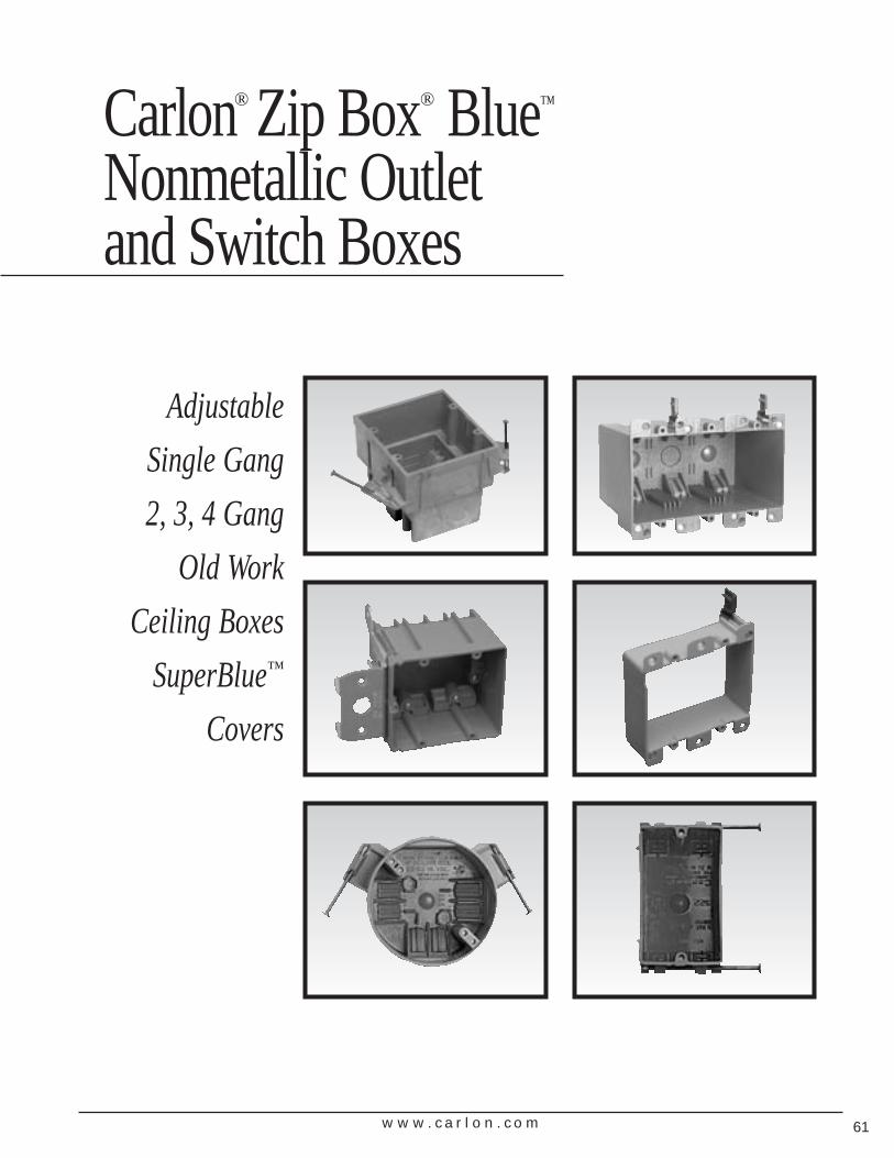
w w w . c a r l o n . c o m 61
Adjustable
Single Gang
2, 3, 4 Gang
Old Work
Ceiling Boxes
SuperBlue™
Covers
Carlon® Zip Box® Blue™
Nonmetallic Outlet and Switch Boxes
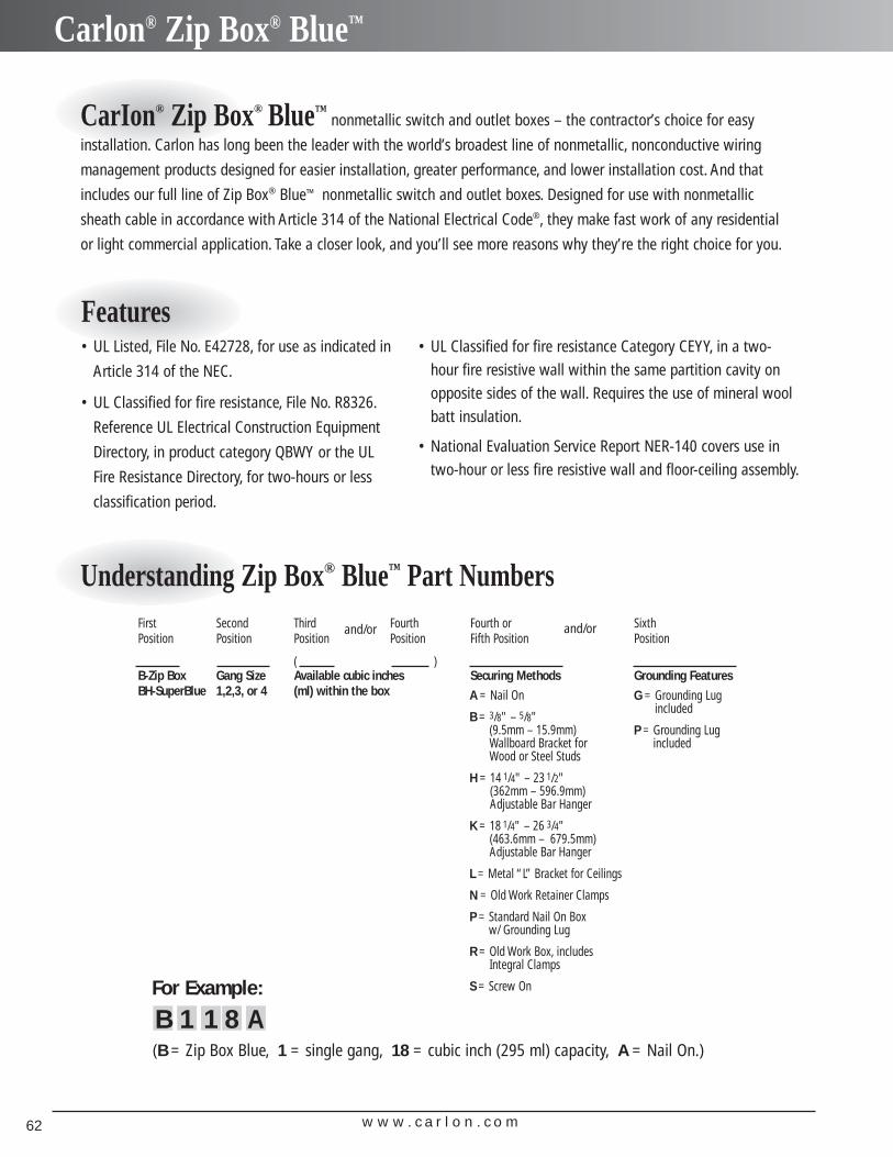
w w w . c a r l o n . c o m62
Carlon® Zip Box® Blue™
CarIon® Zip Box® Blue™nonmetallic switch and outlet boxes – the contractor’s choice for easy
installation. Carlon has long been the leader with the world’s broadest line of nonmetallic, nonconductive wiring
management products designed for easier installation, greater performance, and lower installation cost. And that
includes our full line of Zip Box® Blue™ nonmetallic switch and outlet boxes. Designed for use with nonmetallic
sheath cable in accordance with Article 314 of the National Electrical Code®, they make fast work of any residential
or light commercial application. Take a closer look, and you’ll see more reasons why they’re the right choice for you.
Features• UL Listed, File No. E42728, for use as indicated in
Article 314 of the NEC.
• UL Classified for fire resistance, File No. R8326.
Reference UL Electrical Construction Equipment
Directory, in product category QBWY or the UL
Fire Resistance Directory, for two-hours or less
classification period.
• UL Classified for fire resistance Category CEYY, in a two-hour fire resistive wall within the same partition cavity onopposite sides of the wall. Requires the use of mineral woolbatt insulation.
• National Evaluation Service Report NER-140 covers use intwo-hour or less fire resistive wall and floor-ceiling assembly.
Understanding Zip Box® Blue™ Part NumbersFirst Second Third Fourth Fourth or SixthPosition Position Position Position Fifth Position Position
( )B-Zip Box Gang Size Available cubic inches Securing Methods Grounding FeaturesBH-SuperBlue 1,2,3, or 4 (ml) within the box
and/or and/or
For Example:
B 1 1 8 A(B = Zip Box Blue, 1 = single gang, 18 = cubic inch (295 ml) capacity, A = Nail On.)
A = Nail On
B = 3/8" – 5/8" (9.5mm – 15.9mm)Wallboard Bracket for Wood or Steel Studs
H = 14 1/4" – 23 1/2" (362mm – 596.9mm)Adjustable Bar Hanger
K = 18 1/4" – 26 3/4" (463.6mm – 679.5mm)Adjustable Bar Hanger
L = Metal “L” Bracket for Ceilings
N = Old Work Retainer Clamps
P = Standard Nail On Box w/ Grounding Lug
R = Old Work Box, includes Integral Clamps
S = Screw On
G = Grounding Lugincluded
P = Grounding Lugincluded
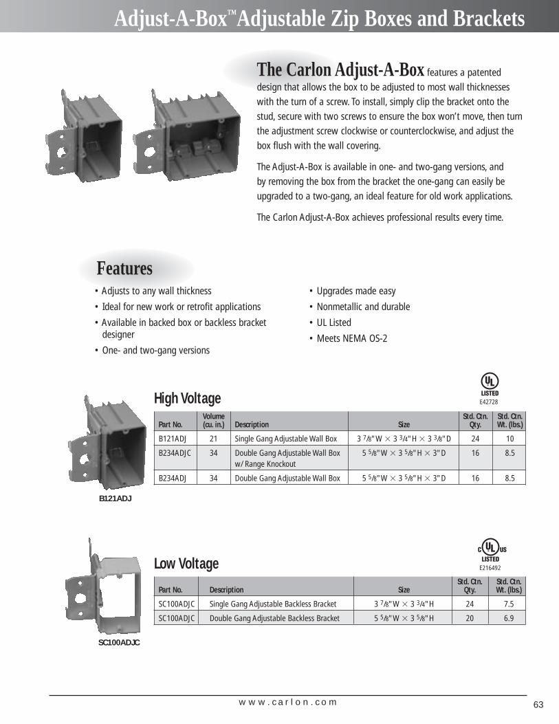
w w w . c a r l o n . c o m 63
Adjust-A-Box™Adjustable Zip Boxes and Brackets
The Carlon Adjust-A-Box features a patenteddesign that allows the box to be adjusted to most wall thicknesseswith the turn of a screw. To install, simply clip the bracket onto thestud, secure with two screws to ensure the box won’t move, then turnthe adjustment screw clockwise or counterclockwise, and adjust thebox flush with the wall covering.
The Adjust-A-Box is available in one- and two-gang versions, and by removing the box from the bracket the one-gang can easily beupgraded to a two-gang, an ideal feature for old work applications.
The Carlon Adjust-A-Box achieves professional results every time.
Features• Adjusts to any wall thickness
• Ideal for new work or retrofit applications
• Available in backed box or backless bracket designer
• One- and two-gang versions
• Upgrades made easy
• Nonmetallic and durable
• UL Listed
• Meets NEMA OS-2
High VoltageVolume Std. Ctn. Std. Ctn.
Part No. (cu. in.) Description Size Qty. Wt. (lbs.)
B121ADJ 21 Single Gang Adjustable Wall Box 3 7/8"W � 3 3/4"H � 3 3/8"D 24 10
B234ADJC 34 Double Gang Adjustable Wall Box 5 5/8"W � 3 5/8"H � 3"D 16 8.5w/ Range Knockout
B234ADJ 34 Double Gang Adjustable Wall Box 5 5/8"W � 3 5/8"H � 3"D 16 8.5
Low VoltageStd. Ctn. Std. Ctn.
Part No. Description Size Qty. Wt. (lbs.)
SC100ADJC Single Gang Adjustable Backless Bracket 3 7/8"W � 3 3/4"H 24 7.5
SC100ADJC Double Gang Adjustable Backless Bracket 5 5/8"W � 3 5/8"H 20 6.9
E42728
E216492
B121ADJ
SC100ADJC
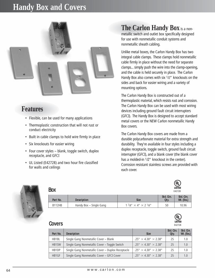
w w w . c a r l o n . c o m64
Handy Box and Covers
Features• Flexible, can be used for many applications
• Thermoplastic construction that will not rust orconduct electricity
• Built in cable clamps to hold wire firmly in place
• Six knockouts for easier wiring
• Four cover styles – blank, toggle switch, duplexreceptacle, and GFCI
• UL Listed (E42728) and two hour fire classified for walls and ceilings
The Carlon Handy Box is a non-metallic switch and outlet box specifically designedfor use with nonmetallic conduit systems and nonmetallic sheath cabling.
Unlike metal boxes, the Carlon Handy Box has twointegral cable clamps. These clamps hold nonmetalliccable firmly in place without the need for separateclamps... simply push the wire into the clamp-opening,and the cable is held securely in place. The CarlonHandy Box also comes with six 1/2" knockouts on thesides and back for easier wiring and a variety ofmounting options.
The Carlon Handy Box is constructed out of a thermoplastic material, which resists rust and corrosion.The Carlon Handy Box can be used with most wiringdevices including ground fault circuit interrupters(GFCI). The Handy Box is designed to accept standardmetal covers or the NEW Carlon nonmetallic HandyBox covers.
The Carlon Handy Box covers are made from adurable polycarbonate material for extra strength anddurability. They’re available in four styles including aduplex receptacle, toggle switch, ground fault circuitinterrupter (GFCI), and a blank cover (the blank coverhas a molded-in 1/2" knockout in the center).Corrosion resistant stainless screws are provided witheach cover.
BoxStd. Ctn. Std. Ctn.
Part No. Description Size Qty. Wt. (lbs.)
B112HB Handy Box – Single Gang 1 7/8" � 4" � 2 1/8" 50 10.96
E42728
CoversStd. Ctn. Std. Ctn.
Part No. Description Size Qty. Wt. (lbs.)
HB1BL Single Gang Nonmetallic Cover – Blank .25" � 4.30" � 2.38" 25 1.0
HB1SW Single Gang Nonmetallic Cover – Toggle Switch .25" � 4.30" � 2.38" 25 1.0
HB1DP Single Gang Nonmetallic Cover – Duplex Receptacle .25" � 4.30" � 2.38" 25 1.0
HB1GF Single Gang Nonmetallic Cover – GFCI Cover .25" � 4.30" � 2.38" 25 1.0
E42728
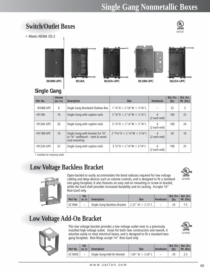
w w w . c a r l o n . c o m 65
Single Gang Nonmetallic Boxes
Switch/Outlet BoxesE42728
Volume Std. Ctn. Std. Ctn.Part No. (cu. in.) Description Size Knockouts Qty. Wt. (lbs.)
B108B-UPC 8 Single Gang Bracketed Shallow Box 1 1/4"D � 2 3/8"W � 3 5/8"L – 25 3
•B118A 18 Single Gang with captive nails 2 7/8"D � 2 1/4"W � 3 3/4"L 4 100 22(2 each end)
•B120A-UPC 20 Single Gang with captive nails 3 1/4"D � 2 1/4"W � 3 7/8"L 4 100 24(2 each end)
•B118B-UPC 18 Single Gang with bracket for 3/8" 2 15/16"D � 2 1/4"W � 3 3/4"L 4 50 10to 5/8" wallboard – steel & wood (2 each end)stud mounting
•B122A-UPC 22 Single Gang with captive nails 3 1/2"D � 2 1/4"W � 3 3/4"L 4 100 25(2 each end)
Vol. Std. Ctn. Std. Ctn.Part No. cu. in. Description Size Knockouts Qty. Wt. (lbs.)
SC100A – Single Gang Backless Bracket 2.32" W � 3.73"L – 24 7.5
Vol. Std. Ctn. Std. Ctn.Part No. cu. in. Description Size Knockouts Qty. Wt. (lbs.)
SC100SC – Single Gang Add-On Bracket 1.80" W � 3.68"L – 24 2.3
Low Voltage Backless Bracket
This low voltage bracket provides a low voltage outlet next to a previouslyinstalled high voltage outlet. Great for both new construction and rework, itattaches easily to most electrical boxes, and is designed to fit a standard two-gang faceplate. Resi-Rings accept 3/4" Resi-Gard only
E216492
E216492
B108B-UPC B118A B120A-UPC B118B-UPC B122A-UPC
Open-backed to easily accommodate the bend radiuses required for low voltagecabling and deep devices such as volume controls, and is designed to fit a standardone-gang faceplate. It also features an easy nail-on mounting or screw-in bracket,while the hard shell provides increased durability and no racking. Accepts 3/4" Resi-Gard only.
Low Voltage Add-On Bracket
• Suitable for masonry walls
Single Gang
• Meets NEMA OS-2
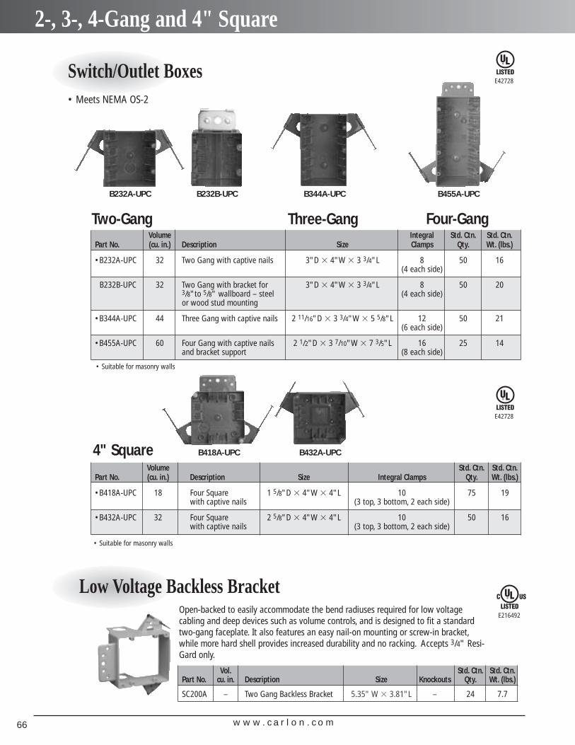
w w w . c a r l o n . c o m66
2-, 3-, 4-Gang and 4" Square
Switch/Outlet BoxesE42728
E42728
Volume Integral Std. Ctn. Std. Ctn.Part No. (cu. in.) Description Size Clamps Qty. Wt. (lbs.)
•B232A-UPC 32 Two Gang with captive nails 3"D � 4"W � 3 3/4"L 8 50 16(4 each side)
B232B-UPC 32 Two Gang with bracket for 3"D � 4"W � 3 3/4"L 8 50 203/8"to 5/8" wallboard – steel (4 each side)or wood stud mounting
•B344A-UPC 44 Three Gang with captive nails 2 11/16"D � 3 3/4"W � 5 5/8"L 12 50 21(6 each side)
•B455A-UPC 60 Four Gang with captive nails 2 1/2"D � 3 7/10"W � 7 3/5"L 16 25 14and bracket support (8 each side)
Volume Std. Ctn. Std. Ctn.Part No. (cu. in.) Description Size Integral Clamps Qty. Wt. (lbs.)
•B418A-UPC 18 Four Square 1 5/8"D � 4"W � 4"L 10 75 19with captive nails (3 top, 3 bottom, 2 each side)
•B432A-UPC 32 Four Square 2 5/8"D � 4"W � 4"L 10 50 16with captive nails (3 top, 3 bottom, 2 each side)
B232A-UPC B344A-UPC B455A-UPCB232B-UPC
B418A-UPC B432A-UPC
Low Voltage Backless Bracket E216492
Open-backed to easily accommodate the bend radiuses required for low voltagecabling and deep devices such as volume controls, and is designed to fit a standardtwo-gang faceplate. It also features an easy nail-on mounting or screw-in bracket,while more hard shell provides increased durability and no racking. Accepts 3/4" Resi-Gard only.
Two-Gang Three-Gang Four-Gang
4" Square
• Suitable for masonry walls
• Suitable for masonry walls
Vol. Std. Ctn. Std. Ctn.Part No. cu. in. Description Size Knockouts Qty. Wt. (lbs.)
SC200A – Two Gang Backless Bracket 5.35" W � 3.81"L – 24 7.7
• Meets NEMA OS-2
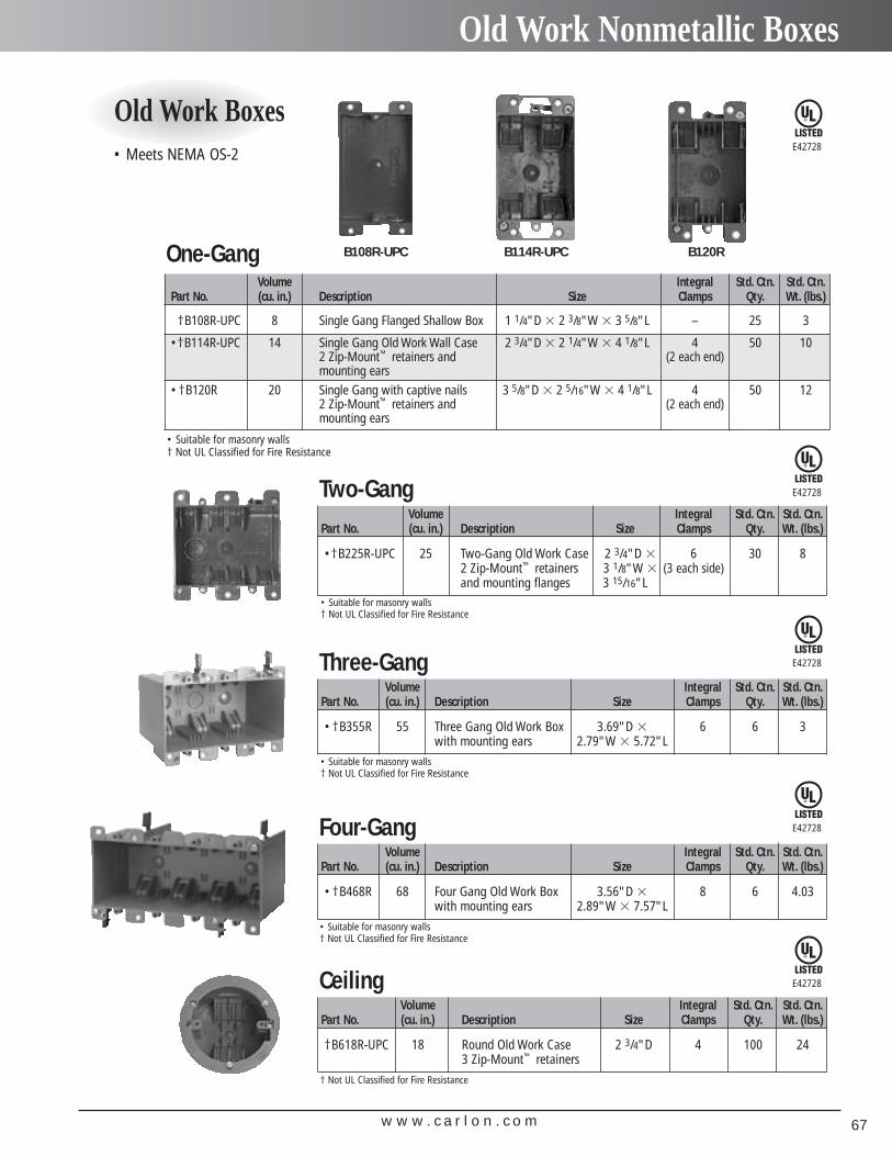
w w w . c a r l o n . c o m 67
Old Work Nonmetallic Boxes
Old Work BoxesE42728
E42728
E42728
E42728
Volume Integral Std. Ctn. Std. Ctn.Part No. (cu. in.) Description Size Clamps Qty. Wt. (lbs.)
†B108R-UPC 8 Single Gang Flanged Shallow Box 1 1/4"D � 2 3/8"W � 3 5/8"L – 25 3
•†B114R-UPC 14 Single Gang Old Work Wall Case 2 3/4"D � 2 1/4"W � 4 1/8"L 4 50 102 Zip-Mount™ retainers and (2 each end)mounting ears
•†B120R 20 Single Gang with captive nails 3 5/8"D � 2 5/16"W � 4 1/8"L 4 50 122 Zip-Mount™ retainers and (2 each end)mounting ears
B108R-UPC B114R-UPC B120R
• Suitable for masonry walls† Not UL Classified for Fire Resistance
One-Gang
Volume Integral Std. Ctn. Std. Ctn.Part No. (cu. in.) Description Size Clamps Qty. Wt. (lbs.)
•†B225R-UPC 25 Two-Gang Old Work Case 2 3/4"D � 6 30 82 Zip-Mount™ retainers 3 1/8"W � (3 each side)and mounting flanges 3 15/16"L
• Suitable for masonry walls† Not UL Classified for Fire Resistance
Two-Gang
Volume Integral Std. Ctn. Std. Ctn.Part No. (cu. in.) Description Size Clamps Qty. Wt. (lbs.)
•†B355R 55 Three Gang Old Work Box 3.69"D � 6 6 3with mounting ears 2.79"W � 5.72"L
• Suitable for masonry walls† Not UL Classified for Fire Resistance
Three-Gang
E42728
Volume Integral Std. Ctn. Std. Ctn.Part No. (cu. in.) Description Size Clamps Qty. Wt. (lbs.)
•†B468R 68 Four Gang Old Work Box 3.56"D � 8 6 4.03with mounting ears 2.89"W � 7.57"L
• Suitable for masonry walls† Not UL Classified for Fire Resistance
Four-Gang
Volume Integral Std. Ctn. Std. Ctn.Part No. (cu. in.) Description Size Clamps Qty. Wt. (lbs.)
†B618R-UPC 18 Round Old Work Case 2 3/4"D 4 100 243 Zip-Mount™ retainers
† Not UL Classified for Fire Resistance
Ceiling
• Meets NEMA OS-2
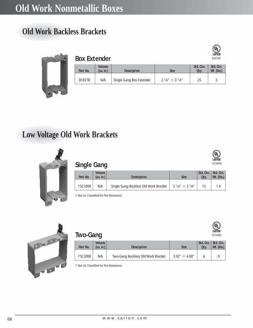
w w w . c a r l o n . c o m68
Old Work Nonmetallic Boxes
E42728
E216492
E216492
Old Work Backless Brackets
Volume Std. Ctn. Std. Ctn.Part No. (cu. in.) Description Size Qty. Wt. (lbs.)
B1EXTB N/A Single Gang Box Extender 2 1/4" � 3 1/4" 25 3
Box Extender
Low Voltage Old Work Brackets
Volume Std. Ctn. Std. Ctn.Part No. (cu. in.) Description Size Qty. Wt. (lbs.)
†SC100R N/A Single Gang Backless Old Work Bracket 2 1/4" � 3 1/4" 12 1.4
† Not UL Classified for Fire Resistance
Single Gang
Volume Std. Ctn. Std. Ctn.Part No. (cu. in.) Description Size Qty. Wt. (lbs.)
†SC200R N/A Two-Gang Backless Old Work Bracket 3.92" � 4.00" 6 .9
† Not UL Classified for Fire Resistance
Two-Gang
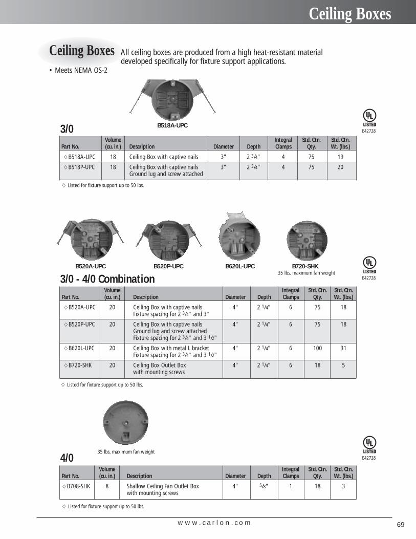
w w w . c a r l o n . c o m 69
Ceiling Boxes
Ceiling Boxes All ceiling boxes are produced from a high heat-resistant materialdeveloped specifically for fixture support applications.
E42728
E42728
E42728
Volume Integral Std. Ctn. Std. Ctn.Part No. (cu. in.) Description Diameter Depth Clamps Qty. Wt. (lbs.)
�B518A-UPC 18 Ceiling Box with captive nails 3" 2 3/4" 4 75 19
�B518P-UPC 18 Ceiling Box with captive nails 3" 2 3/4" 4 75 20Ground lug and screw attached
� Listed for fixture support up to 50 lbs.
3/0 B518A-UPC
Volume Integral Std. Ctn. Std. Ctn.Part No. (cu. in.) Description Diameter Depth Clamps Qty. Wt. (lbs.)
�B520A-UPC 20 Ceiling Box with captive nails 4" 2 1/4" 6 75 18Fixture spacing for 2 3/4" and 3"
�B520P-UPC 20 Ceiling Box with captive nails 4" 2 1/4" 6 75 18Ground lug and screw attachedFixture spacing for 2 3/4" and 3 1/2"
�B620L-UPC 20 Ceiling Box with metal L bracket 4" 2 1/4" 6 100 31Fixture spacing for 2 3/4" and 3 1/2"
�B720-SHK 20 Ceiling Box Outlet Box 4" 2 1/4" 6 18 5with mounting screws
� Listed for fixture support up to 50 lbs.
3/0 - 4/0 CombinationB520A-UPC B520P-UPC B620L-UPC B720-SHK
35 lbs. maximum fan weight
Volume Integral Std. Ctn. Std. Ctn.Part No. (cu. in.) Description Diameter Depth Clamps Qty. Wt. (lbs.)
�B708-SHK 8 Shallow Ceiling Fan Outlet Box 4" 5/8" 1 18 3with mounting screws
� Listed for fixture support up to 50 lbs.
4/0 35 lbs. maximum fan weight
• Meets NEMA OS-2
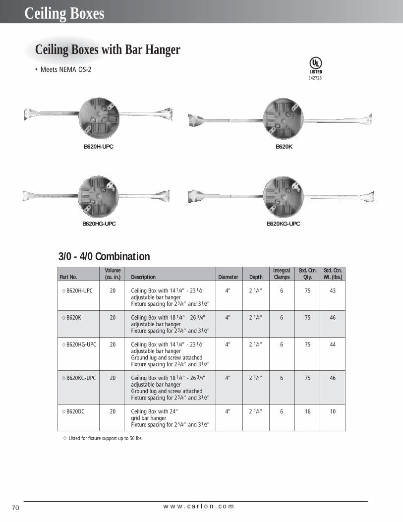
w w w . c a r l o n . c o m70
Ceiling Boxes
E42728
Ceiling Boxes with Bar Hanger
Volume Integral Std. Ctn. Std. Ctn.Part No. (cu. in.) Description Diameter Depth Clamps Qty. Wt. (lbs.)
�B620H-UPC 20 Ceiling Box with 14 1/4" - 23 1/2" 4" 2 1/4" 6 75 43adjustable bar hangerFixture spacing for 23/4" and 31/2"
�B620K 20 Ceiling Box with 18 1/4" - 26 3/4" 4" 2 1/4" 6 75 46adjustable bar hangerFixture spacing for 23/4" and 31/2"
�B620HG-UPC 20 Ceiling Box with 14 1/4" - 23 1/2" 4" 2 1/4" 6 75 44adjustable bar hangerGround lug and screw attachedFixture spacing for 23/4" and 31/2"
�B620KG-UPC 20 Ceiling Box with 18 1/4" - 26 3/4" 4" 2 1/4" 6 75 46adjustable bar hangerGround lug and screw attachedFixture spacing for 23/4" and 31/2"
�B620DC 20 Ceiling Box with 24" 4" 2 1/4" 6 16 10grid bar hangerFixture spacing for 23/4" and 31/2"
� Listed for fixture support up to 50 lbs.
3/0 - 4/0 Combination
B620H-UPC B620K
B620HG-UPC B620KG-UPC
• Meets NEMA OS-2
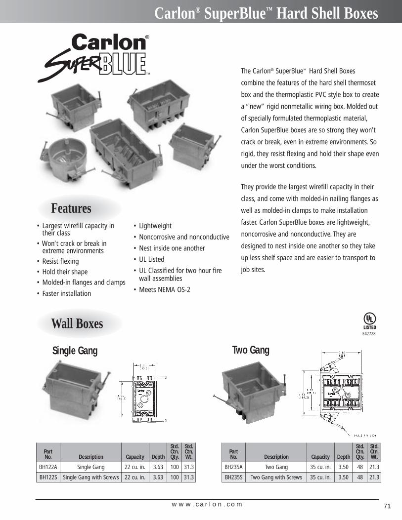
w w w . c a r l o n . c o m 71
Carlon® SuperBlue™ Hard Shell Boxes
Wall Boxes
Two GangSingle Gang
Std. Std.Part Ctn. Ctn.No. Description Capacity Depth Qty. Wt.
BH122A Single Gang 22 cu. in. 3.63 100 31.3
BH122S Single Gang with Screws 22 cu. in. 3.63 100 31.3
Std. Std.Part Ctn. Ctn.No. Description Capacity Depth Qty. Wt.
BH235A Two Gang 35 cu. in. 3.50 48 21.3
BH235S Two Gang with Screws 35 cu. in. 3.50 48 21.3
The Carlon® SuperBlue™ Hard Shell Boxes
combine the features of the hard shell thermoset
box and the thermoplastic PVC style box to create
a “new” rigid nonmetallic wiring box. Molded out
of specially formulated thermoplastic material,
Carlon SuperBlue boxes are so strong they won’t
crack or break, even in extreme environments. So
rigid, they resist flexing and hold their shape even
under the worst conditions.
They provide the largest wirefill capacity in their
class, and come with molded-in nailing flanges as
well as molded-in clamps to make installation
faster. Carlon SuperBlue boxes are lightweight,
noncorrosive and nonconductive. They are
designed to nest inside one another so they take
up less shelf space and are easier to transport to
job sites.
• Lightweight
• Noncorrosive and nonconductive
• Nest inside one another
• UL Listed
• UL Classified for two hour firewall assemblies
• Meets NEMA OS-2
E42728
Features• Largest wirefill capacity in
their class• Won’t crack or break in
extreme environments• Resist flexing• Hold their shape• Molded-in flanges and clamps
• Faster installation
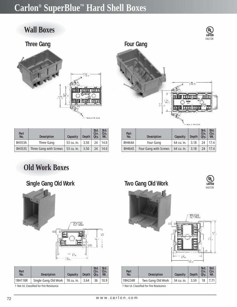
w w w . c a r l o n . c o m72
Carlon® SuperBlue™ Hard Shell Boxes
Three Gang Four Gang
Single Gang Old Work Two Gang Old Work
Wall Boxes
Old Work Boxes
E42728
E42728
Std. Std.Part Ctn. Ctn.No. Description Capacity Depth Qty. Wt.
BH353A Three Gang 53 cu. in. 3.50 24 14.0
BH353S Three Gang with Screws 53 cu. in. 3.50 24 14.0
Std. Std.Part Ctn. Ctn.No. Description Capacity Depth Qty. Wt.
BH464A Four Gang 64 cu. in. 3.18 24 17.4
BH464S Four Gang with Screws 64 cu. in. 3.18 24 17.4
Std. Std.Part Ctn. Ctn.No. Description Capacity Depth Qty. Wt.
†BH118R Single Gang Old Work 18 cu. in. 3.64 36 10.9
† Not UL Classified for Fire Resistance
Std. Std.Part Ctn. Ctn.No. Description Capacity Depth Qty. Wt.
†BH234R Two Gang Old Work 34 cu. in. 3.59 18 7.71
† Not UL Classified for Fire Resistance
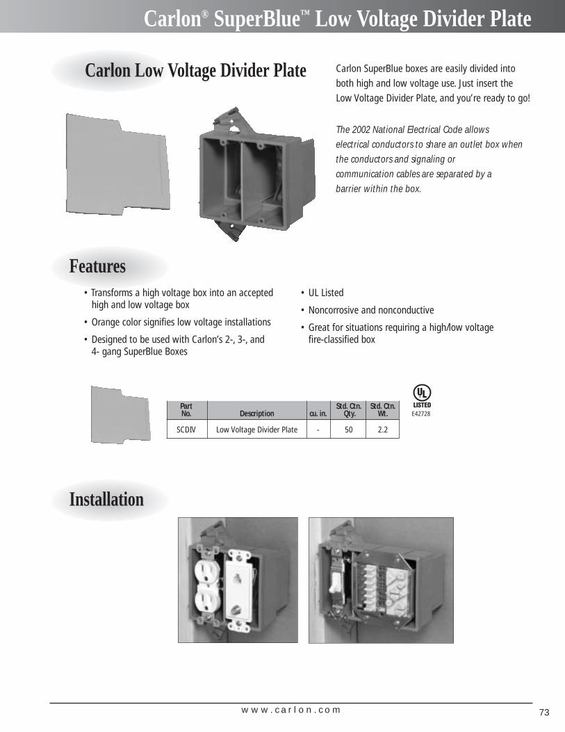
w w w . c a r l o n . c o m 73
Carlon® SuperBlue™ Low Voltage Divider Plate
Carlon Low Voltage Divider Plate Carlon SuperBlue boxes are easily divided intoboth high and low voltage use. Just insert theLow Voltage Divider Plate, and you’re ready to go!
The 2002 National Electrical Code allows electrical conductors to share an outlet box whenthe conductors and signaling or communication cables are separated by a barrier within the box.
Features
Installation
• Transforms a high voltage box into an accepted high and low voltage box
• Orange color signifies low voltage installations
• Designed to be used with Carlon’s 2-, 3-, and 4- gang SuperBlue Boxes
• UL Listed
• Noncorrosive and nonconductive
• Great for situations requiring a high/low voltage fire-classified box
Part Std. Ctn. Std. Ctn.No. Description cu. in. Qty. Wt.
SCDIV Low Voltage Divider Plate - 50 2.2
E42728
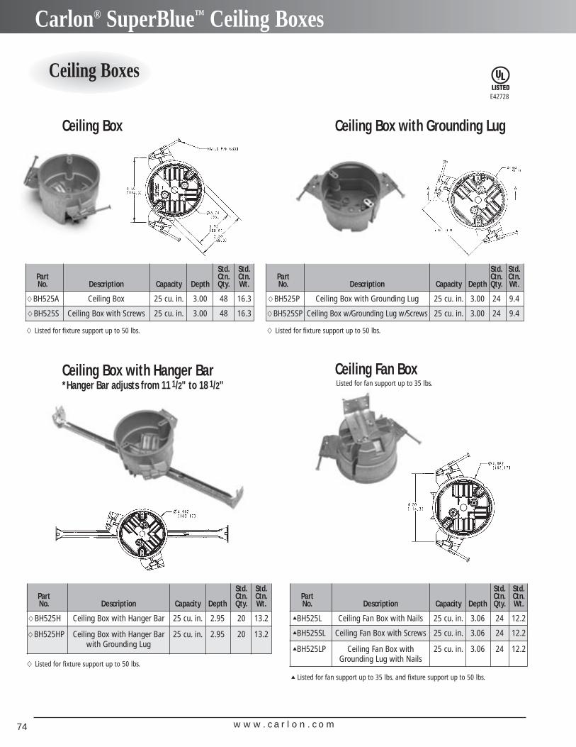
w w w . c a r l o n . c o m74
Carlon® SuperBlue™ Ceiling Boxes
Ceiling Boxes
Ceiling Box Ceiling Box with Grounding Lug
Ceiling Box with Hanger Bar*Hanger Bar adjusts from 11 1/2" to 18 1/2"
Ceiling Fan Box
Std. Std.Part Ctn. Ctn.No. Description Capacity Depth Qty. Wt.
�BH525H Ceiling Box with Hanger Bar 25 cu. in. 2.95 20 13.2
�BH525HP Ceiling Box with Hanger Bar 25 cu. in. 2.95 20 13.2with Grounding Lug
Std. Std.Part Ctn. Ctn.No. Description Capacity Depth Qty. Wt.
▲BH525L Ceiling Fan Box with Nails 25 cu. in. 3.06 24 12.2
▲BH525SL Ceiling Fan Box with Screws 25 cu. in. 3.06 24 12.2
▲BH525LP Ceiling Fan Box with 25 cu. in. 3.06 24 12.2Grounding Lug with Nails
E42728
Std. Std.Part Ctn. Ctn.No. Description Capacity Depth Qty. Wt.
�BH525A Ceiling Box 25 cu. in. 3.00 48 16.3
�BH525S Ceiling Box with Screws 25 cu. in. 3.00 48 16.3
� Listed for fixture support up to 50 lbs.
Std. Std.Part Ctn. Ctn.No. Description Capacity Depth Qty. Wt.
�BH525P Ceiling Box with Grounding Lug 25 cu. in. 3.00 24 9.4
�BH525SP Ceiling Box w/Grounding Lug w/Screws 25 cu. in. 3.00 24 9.4
� Listed for fixture support up to 50 lbs.
� Listed for fixture support up to 50 lbs.
▲ Listed for fan support up to 35 lbs. and fixture support up to 50 lbs.
Listed for fan support up to 35 lbs.
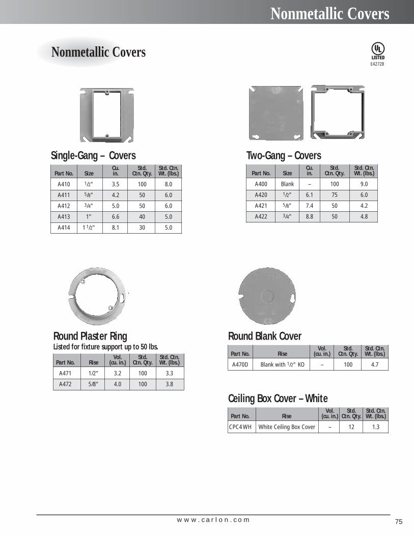
w w w . c a r l o n . c o m 75
Nonmetallic Covers
Nonmetallic Covers
Cu. Std. Std. Ctn.Part No. Size in. Ctn. Qty. Wt. (lbs.)
A410 1/2" 3.5 100 8.0
A411 5/8" 4.2 50 6.0
A412 3/4" 5.0 50 6.0
A413 1" 6.6 40 5.0
A414 1 1/2" 8.1 30 5.0
Single-Gang – CoversCu. Std. Std. Ctn.
Part No. Size in. Ctn. Qty. Wt. (lbs.)
A400 Blank – 100 9.0
A420 1/2" 6.1 75 6.0
A421 5/8" 7.4 50 4.2
A422 3/4" 8.8 50 4.8
Two-Gang – Covers
Vol. Std. Std. Ctn.Part No. Rise (cu. in.) Ctn. Qty. Wt. (lbs.)
A471 1/2" 3.2 100 3.3
A472 5/8" 4.0 100 3.8
Round Plaster RingListed for fixture support up to 50 lbs. Vol. Std. Std. Ctn.
Part No. Rise (cu. in.) Ctn. Qty. Wt. (lbs.)
A470D Blank with 1/2" KO – 100 4.7
Round Blank Cover
Vol. Std. Std. Ctn.Part No. Rise (cu. in.) Ctn. Qty. Wt. (lbs.)
CPC4 WH White Ceiling Box Cover – 12 1.3
Ceiling Box Cover – White
E42728
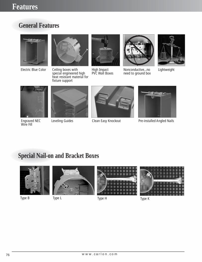
w w w . c a r l o n . c o m76
Features
Electric Blue Color Nonconductive...noneed to ground box
LightweightCeiling boxes with special engineered highheat resistant material forfixture support
High Impact PVC Wall Boxes
Engraved NECWire Fill
Leveling Guides Clean Easy Knockout Pre-installed Angled Nails
General Features
Special Nail-on and Bracket Boxes
Type B Type L Type H Type K
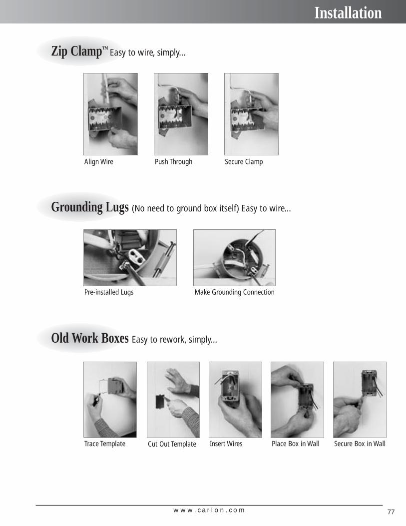
w w w . c a r l o n . c o m 77
Installation
Zip Clamp™ Easy to wire, simply...
Grounding Lugs (No need to ground box itself) Easy to wire...
Old Work Boxes Easy to rework, simply...
Align Wire Push Through Secure Clamp
Pre-installed Lugs Make Grounding Connection
Trace Template Cut Out Template Place Box in Wall Secure Box in WallInsert Wires

w w w . c a r l o n . c o m78
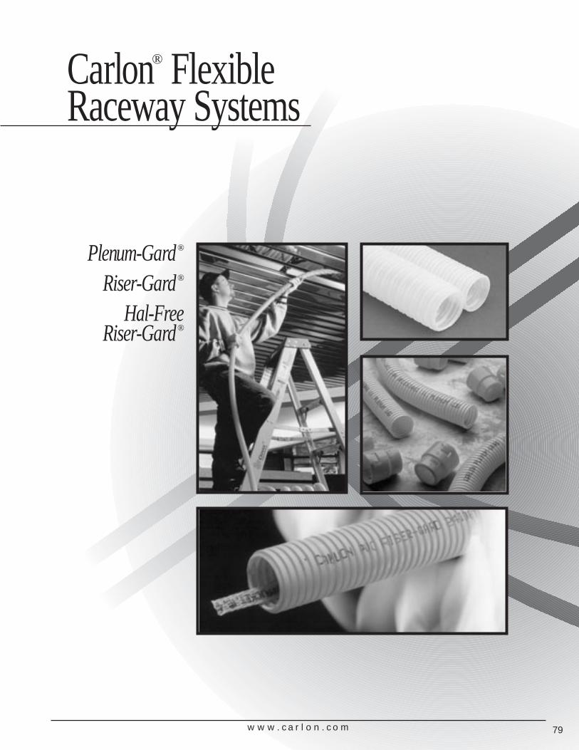
Plenum-Gard®
Riser-Gard®
Hal-FreeRiser-Gard®
Carlon® FlexibleRaceway Systems
w w w . c a r l o n . c o m 79
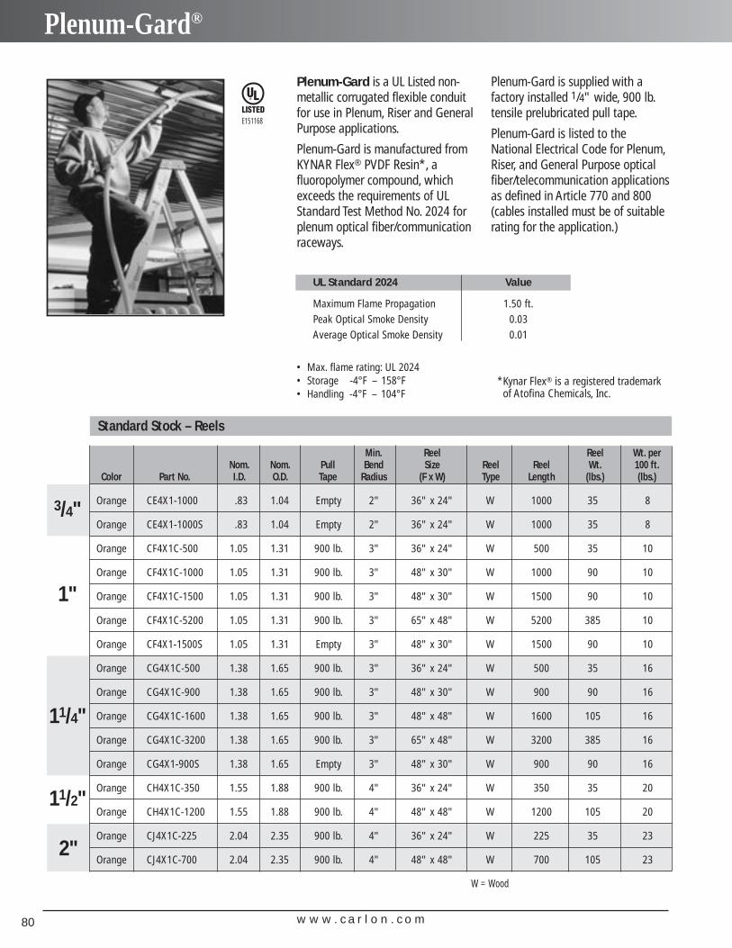
w w w . c a r l o n . c o m80
Plenum-Gard®
Plenum-Gard is a UL Listed non-metallic corrugated flexible conduitfor use in Plenum, Riser and GeneralPurpose applications.
Plenum-Gard is manufactured from KYNAR Flex® PVDF Resin*, a fluoropolymer compound, whichexceeds the requirements of ULStandard Test Method No. 2024 forplenum optical fiber/communication raceways.
Plenum-Gard is supplied with a factory installed 1/4" wide, 900 lb.tensile prelubricated pull tape.
Plenum-Gard is listed to theNational Electrical Code for Plenum,Riser, and General Purpose opticalfiber/telecommunication applications as defined in Article 770 and 800(cables installed must be of suitablerating for the application.)
UL Standard 2024 Value
Maximum Flame Propagation 1.50 ft.Peak Optical Smoke Density 0.03Average Optical Smoke Density 0.01
E151168
Min. Reel Reel Wt. perNom. Nom. Pull Bend Size Reel Reel Wt. 100 ft.
Color Part No. I.D. O.D. Tape Radius (F x W) Type Length (lbs.) (lbs.)
Orange CE4X1-1000 .83 1.04 Empty 2" 36" x 24" W 1000 35 8
Orange CE4X1-1000S .83 1.04 Empty 2" 36" x 24" W 1000 35 8
Orange CF4X1C-500 1.05 1.31 900 lb. 3" 36" x 24" W 500 35 10
Orange CF4X1C-1000 1.05 1.31 900 lb. 3" 48" x 30" W 1000 90 10
Orange CF4X1C-1500 1.05 1.31 900 lb. 3" 48" x 30" W 1500 90 10
Orange CF4X1C-5200 1.05 1.31 900 lb. 3" 65" x 48" W 5200 385 10
Orange CF4X1-1500S 1.05 1.31 Empty 3" 48" x 30" W 1500 90 10
Orange CG4X1C-500 1.38 1.65 900 lb. 3" 36" x 24" W 500 35 16
Orange CG4X1C-900 1.38 1.65 900 lb. 3" 48" x 30" W 900 90 16
Orange CG4X1C-1600 1.38 1.65 900 lb. 3" 48" x 48" W 1600 105 16
Orange CG4X1C-3200 1.38 1.65 900 lb. 3" 65" x 48" W 3200 385 16
Orange CG4X1-900S 1.38 1.65 Empty 3" 48" x 30" W 900 90 16
Orange CH4X1C-350 1.55 1.88 900 lb. 4" 36" x 24" W 350 35 20
Orange CH4X1C-1200 1.55 1.88 900 lb. 4" 48" x 48" W 1200 105 20
Orange CJ4X1C-225 2.04 2.35 900 lb. 4" 36" x 24" W 225 35 23
Orange CJ4X1C-700 2.04 2.35 900 lb. 4" 48" x 48" W 700 105 23
1"
2"
11/4"
3/4"
11/2"
Standard Stock – Reels
• Max. flame rating: UL 2024• Storage -4°F – 158°F • Handling -4°F – 104°F
*Kynar Flex® is a registered trademarkof Atofina Chemicals, Inc.
W = Wood
w w w . c a r l o n . c o m 81
Plenum-Gard®
Features: Custom Orders:• For use in Plenum areas per Articles 770
and 800.
• 3/4" through 2"
• Pull tape pre-installed in 1" through 2"
• Outside Diameters meet IPS Dimensions
• UL Listed raceway meeting UL 2024
• Footage sequentially marked
C u s t o m O r d e r s
H o w t o B u i l d a P a r t N u m b e rPosition 1 Position 2 Position 3 Position 4 Position 5 Position 6 Position 7Product Size Configuration Wall Color Pull Line Length
C = Plenum-Gard E = 3/4" 4 = Corrugated X = Standard 1 = Orange C = 900 lb. Tape ExampleF = 1" 2 = Black -1000 = FeetG = 11/4" 3 = Gray -1000S = 1000 Feet SplitH = 11/2" 4 = WhiteJ = 2" 5 = Blue
6 = Green7 = Yellow8 = Red
Min. Coil Wt. perNom. Nom. Pull Bend Length 100 ft.
Color Part No. I.D. O.D. Tape Radius (ft.) (lbs.)
Orange CE4X1-350* .83 1.04 Empty 2" 350 8
Orange CE4X1-350S* .83 1.04 Empty 2" 350 8
Orange CF4X1C-100 1.05 1.31 900 lb. 3" 100 10
Orange CF4X1C-250* 1.05 1.31 900 lb. 3" 250 10
Orange CF4X1-250S* 1.05 1.31 Empty 3" 250 10
Orange CG4X1C-200* 1.38 1.65 900 lb. 3" 200 16
Orange CG4X1-200S* 1.38 1.65 Empty 3" 200 16
Orange CH4X1C-150* 1.55 1.88 900 lb. 4" 150 20
Orange CH4X1-150S* 1.55 1.88 Empty 4" 150 20
Orange CJ4X1C-100* 2.04 2.35 900 lb. 4" 100 23
Orange CJ4X1-100S* 2.04 2.35 Empty 4" 100 23
Standard Stock – Coils
1"
2"
11/4"
3/4"
11/2"
* Overnight Shippable
• Custom Orders are not returnable• Custom lengths are available in minimum order quantities
of 1000 ft.• Custom color runs are available in minimum order quantities
of 10,000 ft.
Options:• Color: Black, Blue, Grey, Green, Red, White and Yellow• Two, three, or four way parallel• Split Duct• Custom print line
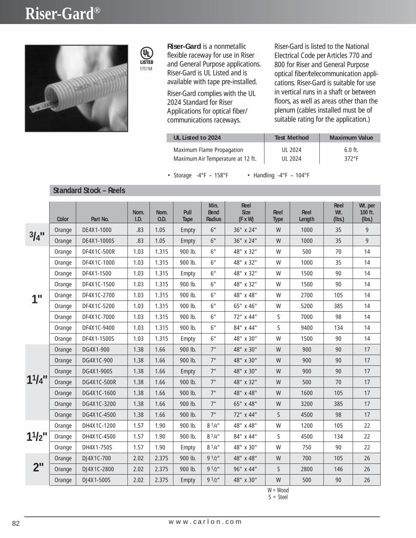
w w w . c a r l o n . c o m82
Riser-Gard®
Riser-Gard is a nonmetallic flexible raceway for use in Riserand General Purpose applications.Riser-Gard is UL Listed and is available with tape pre-installed.
Riser-Gard complies with the UL2024 Standard for RiserApplications for optical fiber/communications raceways.
UL Listed to 2024 Test Method Maximum Value
Maximum Flame Propagation UL 2024 6.0 ft.Maximum Air Temperature at 12 ft. UL 2024 372°F
E151168
Min. Reel Reel Wt. perNom. Nom. Pull Bend Size Reel Reel Wt. 100 ft.
Color Part No. I.D. O.D. Tape Radius (F x W) Type Length (lbs.) (lbs.)
Orange DE4X1-1000 .83 1.05 Empty 6" 36" x 24" W 1000 35 9
Orange DE4X1-1000S .83 1.05 Empty 6" 36" x 24" W 1000 35 9
Orange DF4X1C-500R 1.03 1.315 900 lb. 6" 48" x 32" W 500 70 14
Orange DF4X1C-1000 1.03 1.315 900 lb. 6" 48" x 32" W 1000 35 14
Orange DF4X1-1500 1.03 1.315 Empty 6" 48" x 32" W 1500 90 14
Orange DF4X1C-1500 1.03 1.315 900 lb. 6" 48" x 32" W 1500 90 14
Orange DF4X1C-2700 1.03 1.315 900 lb. 6" 48" x 48" W 2700 105 14
Orange DF4X1C-5200 1.03 1.315 900 lb. 6" 65" x 46" W 5200 385 14
Orange DF4X1C-7000 1.03 1.315 900 lb. 6" 72" x 44" S 7000 98 14
Orange DF4X1C-9400 1.03 1.315 900 lb. 6" 84" x 44" S 9400 134 14
Orange DF4X1-1500S 1.03 1.315 Empty 6" 48" x 30" W 1500 90 14
Orange DG4X1-900 1.38 1.66 900 lb. 7" 48" x 30" W 900 90 17
Orange DG4X1C-900 1.38 1.66 900 lb. 7" 48" x 30" W 900 90 17
Orange DG4X1-900S 1.38 1.66 Empty 7" 48" x 30" W 900 90 17
Orange DG4X1C-500R 1.38 1.66 900 lb. 7" 48" x 32" W 500 70 17
Orange DG4X1C-1600 1.38 1.66 900 lb. 7" 48" x 48" W 1600 105 17
Orange DG4X1C-3200 1.38 1.66 900 lb. 7" 65" x 48" W 3200 385 17
Orange DG4X1C-4500 1.38 1.66 900 lb. 7" 72" x 44" S 4500 98 17
Orange DH4X1C-1200 1.57 1.90 900 lb. 8 1/4" 48" x 48" W 1200 105 22
Orange DH4X1C-4500 1.57 1.90 900 lb. 8 1/4" 84" x 44" S 4500 134 22
Orange DH4X1-750S 1.57 1.90 Empty 8 1/4" 48" x 30" W 750 90 22
Orange DJ4X1C-700 2.02 2.375 900 lb. 9 1/2" 48" x 48" W 700 105 26
Orange DJ4X1C-2800 2.02 2.375 900 lb. 9 1/2" 96" x 44" S 2800 146 26
Orange DJ4X1-500S 2.02 2.375 Empty 9 1/2" 48" x 30" W 500 90 26
1"
2"
11/4"
3/4"
11/2"
Standard Stock – Reels
• Storage -4°F – 158°F • Handling -4°F – 104°F
W = WoodS = Steel
Riser-Gard is listed to the NationalElectrical Code per Articles 770 and800 for Riser and General Purposeoptical fiber/telecommunication appli-cations. Riser-Gard is suitable for usein vertical runs in a shaft or betweenfloors, as well as areas other than theplenum (cables installed must be ofsuitable rating for the application.)
w w w . c a r l o n . c o m 83
Riser-Gard®
Features:• For use in Riser and General
Purpose areas per Articles 770and 800 of the NEC.
• Riser-Gard is also suitable fordirect burial. Not approved forexposed applications.NOTE: UL has not evaluatedRiser-Gard for this application.
• UL Listed Raceway meetingUL 2024
• Available in sizes 3/4"through 2"
• Pull tape can be factory pre-installed in 1" through 2"
• Outside Diameters meet IPSDimensions
• Footage sequentially marked
• Sizes 3/4"– 1" are acceptablefor FT4 applications.
C u s t o m O r d e r s
H o w t o B u i l d a P a r t N u m b e rPosition 1 Position 2 Position 3 Position 4 Position 5 Position 6 Position 7Product Size Configuration Wall Color Pull Line Length
D = Riser-Gard E = 3/4" 4 = Corrugated X = Standard 1 = Orange C = 900 lb. Tape ExampleF = 1" 2 = Black -1000 = FeetG = 11/4" 3 = Gray -1000S = 1000 Feet SplitH = 11/2" 4 = WhiteJ = 2" 5 = Blue
6 = Green7 = Yellow8 = Red
Min. Coil Wt. perNom. Nom. Pull Bend Length 100 ft.
Color Part No. I.D. O.D. Tape Radius (ft.) (lbs.)
Orange DE4X1-350* .83 1.04 Empty 6" 350 9
Orange DE4X1-350S* .83 1.04 Empty 6" 350 9
Orange DF4X1-250* 1.05 1.31 Empty 6" 250 14
Orange DF4X1C-250* 1.05 1.31 900 lb. 6" 250 14
Orange DF4X1C-500 1.05 1.31 900 lb. 6" 500 14
Orange DF4X1-250S* 1.05 1.31 Empty 6" 250 14
Orange DG4X1-200 1.38 1.65 Empty 7" 200 17
Orange DG4X1C-200* 1.38 1.65 900 lb. 7" 200 17
Orange DG4X1C-500 1.38 1.65 900 lb. 7" 500 17
Orange DG4X1-200S* 1.38 1.65 Empty 7" 200 17
Orange DH4X1C-150* 1.55 1.88 900 lb. 8 1/4" 150 22
Orange DH4X1-150S* 1.55 1.88 Empty 8 1/4" 150 22
Orange DJ4X1C-100* 2.04 2.35 900 lb. 9 1/2" 100 26
Orange DJ4X1-100S* 2.04 2.35 Empty 9 1/2" 100 26
Standard Stock – Coils
1"
2"
11/4"
3/4"
11/2"
* Overnight Shippable
Custom Orders:• Custom Orders are not returnable• Custom lengths are available in minimum order
quantities of 1000 ft.• Custom color runs are available in minimum order
quantities of 10,000 ft.
Options:• Color: Black, Blue, Grey, Green, Red, White
and Yellow• Two, three, or four way parallel• Split Duct• Custom print line
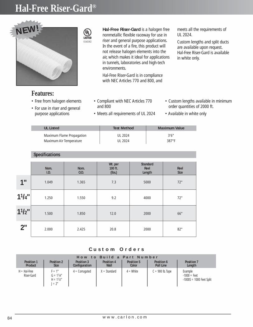
w w w . c a r l o n . c o m84
Hal-Free Riser-Gard®
meets all the requirements ofUL 2024.
Custom lengths and split ductsare available upon request.Hal-Free Riser-Gard is availablein white only.
E143102
UL Listed Test Method Maximum Value
Maximum Flame Propagation UL 2024 3'6"Maximum Air Temperature UL 2024 387°F
C u s t o m O r d e r s
H o w t o B u i l d a P a r t N u m b e rPosition 1 Position 2 Position 3 Position 4 Position 5 Position 6 Position 7Product Size Configuration Wall Color Pull Line Length
H = Hal-Free F = 1" 4 = Corrugated X = Standard 4 = White C = 900 lb. Tape ExampleRiser-Gard G = 11/4" -1000 = Feet
H = 11/2" -1000S = 1000 Feet SplitJ = 2"
Wt. per StandardNom. Nom. 100 ft. Reel ReelI.D. O.D. (lbs.) Length Size
1.049 1.365 7.3 5000 72"
1.250 1.550 9.2 4000 72"
1.500 1.850 12.0 2000 66"
2.000 2.425 20.8 2000 82"
Specifications
1"
2"
11/4"
11/2"
Features:• Free from halogen elements
• For use in riser and general purpose applications
Hal-Free Riser-Gard is a halogen freenonmetallic flexible raceway for use inriser and general purpose applications.In the event of a fire, this product willnot release halogen elements into theair, which makes it ideal for applicationsin tunnels, laboratories and high-tech environments.
Hal-Free Riser-Gard is in compliancewith NEC Articles 770 and 800, and
• Compliant with NEC Articles 770and 800
• Meets all requirements of UL 2024
• Custom lengths available in minimumorder quantities of 2000 ft.
• Available in white only
NEW!
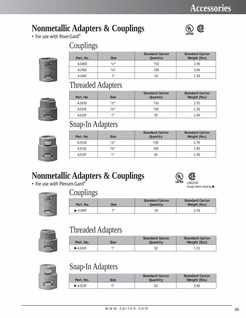
w w w . c a r l o n . c o m 85
Accessories
• For use with Riser-Gard®
Standard Carton Standard CartonPart. No. Size Quantity Weight (lbs.)
A243D 1/2" 150 2.55
A243E 3/4" 100 2.30
A243F 1" 50 2.00
Threaded Adapters
Standard Carton Standard CartonPart. No. Size Quantity Weight (lbs.)
A253D 1/2" 150 2.70
A253E 3/4" 100 2.90
A253F 1" 50 2.30
Snap-In Adapters
Nonmetallic Adapters & Couplings
• For use with Plenum-Gard®
Nonmetallic Adapters & Couplings
Standard Carton Standard CartonPart. No. Size Quantity Weight (lbs.)
A240D 1/2" 150 2.90
A240E 3/4" 100 3.00
A240F 1" 50 2.30
Couplings
Standard Carton Standard CartonPart. No. Size Quantity Weight (lbs.)
A343F 1" 50 1.55
Threaded Adapters
Standard Carton Standard CartonPart. No. Size Quantity Weight (lbs.)
A353F 1" 50 3.00
Snap-In Adapters
Standard Carton Standard CartonPart. No. Size Quantity Weight (lbs.)
A340F 1" 50 2.50
CouplingsLR92248Except where noted by
▲
▲▲
▲
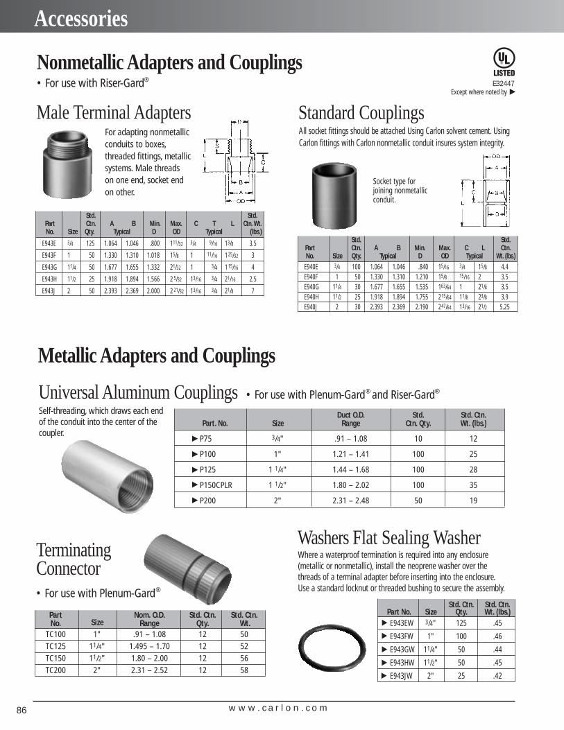
w w w . c a r l o n . c o m86
Accessories
Duct O.D. Std. Std. Ctn.Part. No. Size Range Ctn. Qty. Wt. (lbs.)
P75 3/4" .91 – 1.08 10 12
P100 1" 1.21 – 1.41 100 25
P125 1 1/4" 1.44 – 1.68 100 28
P150CPLR 1 1/2" 1.80 – 2.02 100 35
P200 2" 2.31 – 2.48 50 19
Universal Aluminum Couplings • For use with Plenum-Gard® and Riser-Gard®
Male Terminal AdaptersFor adapting nonmetallicconduits to boxes,threaded fittings, metallicsystems. Male threads on one end, socket endon other.
All socket fittings should be attached Using Carlon solvent cement. UsingCarlon fittings with Carlon nonmetallic conduit insures system integrity.
Standard Couplings
Socket type for joining nonmetallic conduit.
Where a waterproof termination is required into any enclosure(metallic or nonmetallic), install the neoprene washer over thethreads of a terminal adapter before inserting into the enclosure.Use a standard locknut or threaded bushing to secure the assembly.
Washers Flat Sealing Washer
E32447Except where noted by
▲
Nonmetallic Adapters and Couplings• For use with Riser-Gard®
Metallic Adapters and Couplings▲
▲▲
▲▲
Self-threading, which draws each endof the conduit into the center of thecoupler.
Terminating Connector• For use with Plenum-Gard®
Part Nom. O.D. Std. Ctn. Std. Ctn.No. Size Range Qty. Wt.
TC100 1" .91 – 1.08 12 50TC125 11/4" 1.495 – 1.70 12 52TC150 11/2" 1.80 – 2.00 12 56TC200 2" 2.31 – 2.52 12 58
Std. Std.Part Ctn. A B Min. Max. C T L Ctn. Wt.No. Size Qty. Typical D OD Typical (lbs.)
E943E 3/4 125 1.064 1.046 .800 111/32 3/4 9/16 13/8 3.5
E943F 1 50 1.330 1.310 1.018 15/8 1 11/16 125/32 3
E943G 11/4 50 1.677 1.655 1.332 21/32 1 3/4 115/16 4
E943H 11/2 25 1.918 1.894 1.566 2 5/32 13/16 3/4 21/16 2.5
E943J 2 50 2.393 2.369 2.000 2 21/32 13/16 3/4 21/8 7
Std. Std.Part Ctn. A B Min. Max. C L Ctn.No. Size Qty. Typical D OD Typical Wt. (lbs.)
E940E 3/4 100 1.064 1.046 .840 15/16 3/4 15/8 4.4E940F 1 50 1.330 1.310 1.210 15/8 15/16 2 3.5E940G 11/4 30 1.677 1.655 1.535 163/64 1 21/8 3.5E940H 11/2 25 1.918 1.894 1.755 215/64 11/8 23/8 3.9E940J 2 30 2.393 2.369 2.190 247/64 13/16 21/2 5.25
Std. Ctn. Std. Ctn.Part No. Size Qty. Wt. (lbs.)E943EW 3/4" 125 .45
E943FW 1" 100 .46
E943GW 11/4" 50 .44
E943HW 11/2" 50 .45
E943JW 2" 25 .42
▲▲
▲▲
▲
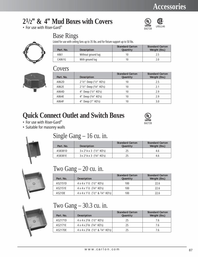
w w w . c a r l o n . c o m 87
Accessories
• For use with Riser-Gard®21/2" & 4" Mud Boxes with Covers
Standard Carton Standard CartonPart. No. Description Quantity Weight (lbs.)
A861 Without ground lug 10 2.5
CA861G With ground lug 10 2.0
Base RingsListed for use with ceiling fans up to 35 lbs. and for fixture support up to 50 lbs.
• For use with Riser-Gard®
• Suitable for masonry walls
Quick Connect Outlet and Switch Boxes
Standard Carton Standard CartonPart. No. Description Quantity Weight (lbs.)
A58381D 3 x 21/4 x 3 (1/2" KO’s) 25 4.6
A58381E 3 x 21/4 x 3 (3/4" KO’s) 25 4.6
Single Gang – 16 cu. in.
Standard Carton Standard CartonPart. No. Description Quantity Weight (lbs.)
A52151D 4 x 4 x 11/2 (1/2" KO’s) 100 22.6
A52151E 4 x 4 x 11/2 (3/4" KO’s) 100 22.6
A521DE 4 x 4 x 11/2 (1/2" & 3/4" KO’s) 100 22.6
Two Gang – 20 cu. in.
Standard Carton Standard CartonPart. No. Description Quantity Weight (lbs.)
A52171D 4 x 4 x 23/8 (1/2" KO’s) 25 7.6
A52171E 4 x 4 x 23/8 (3/4" KO’s) 25 7.6
A5217DE 4 x 4 x 23/8 (1/2" & 3/4" KO’s) 25 7.6
Two Gang – 30.3 cu. in.
Standard Carton Standard CartonPart. No. Description Quantity Weight (lbs.)
A862D 2 1/2" Deep (1/2" KO’s) 10 2.5
A862E 2 1/2" Deep (3/4" KO’s) 10 2.1
A864D 4" Deep (1/2" KO’s) 10 2.9
A864E 4" Deep (3/4" KO’s) 10 2.9
A864F 4" Deep (1" KO’s) 10 3.0
Covers
E42728LR31146
E42728
w w w . c a r l o n . c o m88
Accessories
• For use with Riser-Gard®
ENT Box with Adapters
Standard Carton Standard CartonPart. No. Description Quantity Weight (lbs.)
A5329DE 4 x 4 x 13/4 (1/2" & 3/4" KO’s) 50 14.8
Two Gang – 24.75 cu. in. ENT Box with Adapters
Standard Carton Standard CartonPart. No. Description Quantity Weight (lbs.)
A540DS For use with 1/2" Knockout 100 2.1
Box Back Wall Support
• For use with Riser-Gard®
ENT Box Extenders
Standard Carton Standard CartonPart. No. Rise Cu. in. Quantity Weight (lbs.)
A410 1/2" 3.5 100 7.7
A411 5/8" 4.2 50 4.6
A412 3/4" 5.0 50 5.1
A413 1" 6.6 40 5
A414 11/4" 8.1 30 4.4
Single Gang
Standard Carton Standard CartonPart. No. Rise Cu. in. Quantity Weight (lbs.)
A400 Blank - 100 7.7
A420 1/2" 6.1 75 5.0
A421 5/8" 7.4 50 4.2
A422 3/4" 8.8 50 4.8
Two Gang
E42728
E42728
Except where noted by
▲
▲
• For use with Riser-Gard®
Round Covers for Octagon Ceiling BoxesE42728
Standard Carton Standard CartonPart. No. Rise Cu. in. Quantity Weight (lbs.)
A471 1/2" 3.2 100 3.3
A472 3/4" 4.0 100 3.7
Round Plaster Rings• Suitable for fixture support
Standard Carton Standard CartonPart. No. Rise Cu. in. Quantity Weight (lbs.)
E460R-CAR Blank - 35 2.2
A470D Blank with 1/2" KO - 100 6.2
Round Blank Covers
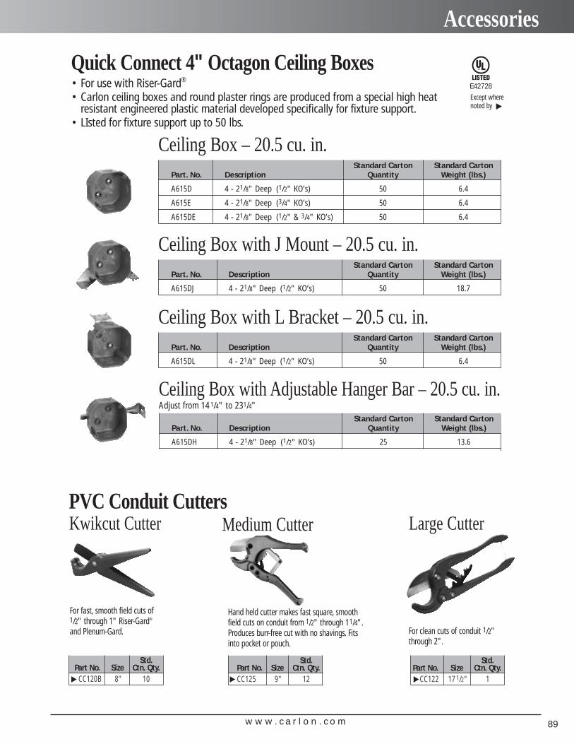
w w w . c a r l o n . c o m 89
Accessories
Std.Part No. Size Ctn. Qty.
CC120B 8" 10
Std.Part No. Size Ctn. Qty.CC125 9" 12
Std.Part No. Size Ctn. Qty.
CC122 17 1/2" 1
PVC Conduit Cutters
Hand held cutter makes fast square, smoothfield cuts on conduit from 1/2" through 11/4".Produces burr-free cut with no shavings. Fitsinto pocket or pouch.
For clean cuts of conduit 1/2"through 2".
For fast, smooth field cuts of 1/2" through 1" Riser-Gard®
and Plenum-Gard.
Kwikcut Cutter Medium Cutter Large Cutter
• For use with Riser-Gard®
• Carlon ceiling boxes and round plaster rings are produced from a special high heatresistant engineered plastic material developed specifically for fixture support.
• LIsted for fixture support up to 50 lbs.
Quick Connect 4" Octagon Ceiling Boxes
Standard Carton Standard CartonPart. No. Description Quantity Weight (lbs.)
A615D 4 - 21/8" Deep (1/2" KO’s) 50 6.4
A615E 4 - 21/8" Deep (3/4" KO’s) 50 6.4
A615DE 4 - 21/8" Deep (1/2" & 3/4" KO’s) 50 6.4
Ceiling Box – 20.5 cu. in.
Standard Carton Standard CartonPart. No. Description Quantity Weight (lbs.)
A615DJ 4 - 21/8" Deep (1/2" KO’s) 50 18.7
Ceiling Box with J Mount – 20.5 cu. in.
E42728
Standard Carton Standard CartonPart. No. Description Quantity Weight (lbs.)
A615DL 4 - 21/8" Deep (1/2" KO’s) 50 6.4
Ceiling Box with L Bracket – 20.5 cu. in.
Ceiling Box with Adjustable Hanger Bar – 20.5 cu. in.Adjust from 141/4" to 231/4"
Standard Carton Standard CartonPart. No. Description Quantity Weight (lbs.)
A615DH 4 - 21/8" Deep (1/2" KO’s) 25 13.6
Except where noted by
▲
▲ ▲ ▲
w w w . c a r l o n . c o m90
Accessories
Carlon® Cement (MSDS sheets available at www.carlon.com)*Meets ASTM D2564
Standard Grade Clear Solvent Cement with dauber*
All-Weather “Quick-Set” Clear Solvent Cement with dauber*
Low VOC Solvent Cement with dauber*
Part Std.No. Size Ctn. Qty.
VC9964 1/2 Pint 10
VC9963 Pint 24
VC9962 Quart 12
VC9961P Gallon 6
Recommended for all gradesand types of Carlon PVC conduit, duct, wireway and fittings, except Flex-Plus®
Blue™ ENT (ElectricalNonmetallic Tubing.) Up through 6" diameter.
Recommended for allgrades and types of CarlonPVC conduit, duct, wirewayand fittings, except Flex-Plus® Blue™ ENT (ElectricalNonmetallic Tubing.) Up through 6" diameter.
Recommended for allgrades and types of CarlonPVC conduit, duct, wirewayand fittings, except Flex-Plus® Blue™ ENT (ElectricalNonmetallic Tubing.) Up through 6" diameter.VOC emission of 490grams/liter per the Bay andSouth Coast test method.
Recommended pipeapplication and sizes
10˚-30˚F Not recommended30˚-50˚F 5-6 minutes50˚-70˚F 3-4 minutes70˚-90˚F 1-2 minutes
10˚-30˚F 4-5 minutes30˚-50˚F 3-4 minutes50˚-70˚F 1-2 minutes70˚-90˚F 1/2-11/2 minutes
10˚-30˚F Not recommended30˚-50˚F 5-6 minutes50˚-70˚F 3-4 minutes70˚-90˚F 1-2 minutes
2 hrs. 350 psi16 hrs. 800 psi72 hrs. 1,500 psi
2 hrs. 350 psi16 hrs. 800 psi72 hrs. 1,500 psi
2 hrs. 350 psi16 hrs. 800 psi72 hrs. 1,500 psi
Set-up time(Evaporation Rate)
Lap Shear@ 73˚F
Recommendedinstallation temperature
40˚ to 100˚F
-5˚ to 100˚F
40˚ to 100˚F
Viscosity at 75˚ asmanufactured
500-900 cps
400-700 cps
500-900 cps
Part Std.No. Size Ctn. Qty.
VC9984 1/2 Pint 10
VC9983 Pint 24
VC9982 Quart 12
VC9981P Gallon 6
Part Std.No. Size Ctn. Qty.
VC9LV4 1/2 Pint 10
VC9LV3 Pint 24
VC9LV2 Quart 12
Other ropes and tapes are available. Consult your sales service location for additional information.
Prelubricated, woven polyester tape made from low friction, high abrasion resistant yarns providing a low coefficient of friction.Tape is printed with sequential footage markings for accurate measurements.Tape
Part. No. Size Tensile Strength Reel Lengths
TL14505 1/2" 1250 lbs. 5,000 ft.
TL14510 1/2" 1250 lbs. 10,000 ft.
TL38203 5/8" 1800 lbs. 3,000 ft.
TL38265 5/8" 1800 lbs. 6,500 ft.
TL38210 5/8" 1800 lbs. 10,000 ft.
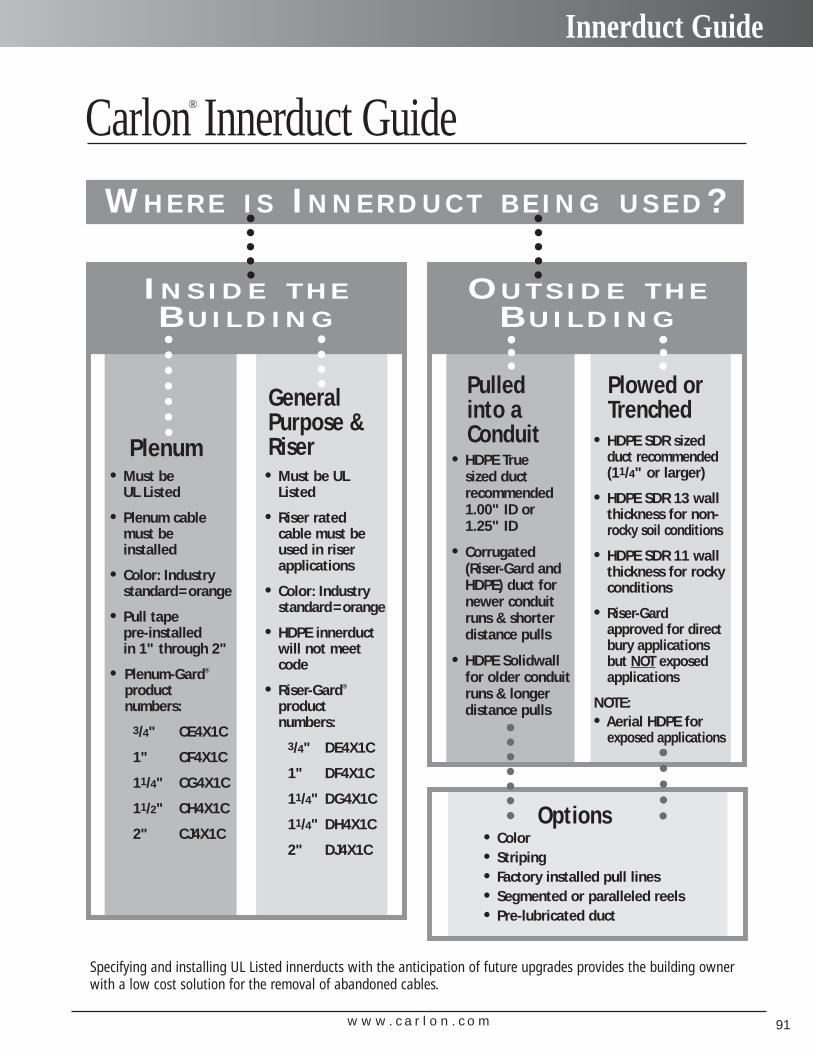
w w w . c a r l o n . c o m 91
Innerduct Guide
Carlon® Innerduct Guide
WH E R E I S IN N E R D U C T B E I N G U S E D?
Plenum
GeneralPurpose &Riser
• Must be UL Listed
• Plenum cablemust be installed
• Color: Industrystandard=orange
• Pull tape pre-installedin 1" through 2"
• Plenum-Gard®
product numbers:
3/4" CE4X1C
1" CF4X1C
11/4" CG4X1C
11/2" CH4X1C
2" CJ4X1C
IN S I D E T H EBU I L D I N G
• Must be ULListed
• Riser rated cable must beused in riserapplications
• Color: Industrystandard=orange
• HDPE innerductwill not meetcode
• Riser-Gard®
product numbers:
3/4" DE4X1C
1" DF4X1C
11/4" DG4X1C
11/4" DH4X1C
2" DJ4X1C
Pulled into aConduit
Plowed or Trenched
• HDPE True sized duct recommended1.00" ID or1.25" ID
• Corrugated(Riser-Gard andHDPE) duct fornewer conduitruns & shorter distance pulls
• HDPE Solidwallfor older conduitruns & longerdistance pulls
OU T S I D E T H EBU I L D I N G
• HDPE SDR sizedduct recommended(11/4" or larger)
• HDPE SDR 13 wallthickness for non-rocky soil conditions
• HDPE SDR 11 wallthickness for rockyconditions
• Riser-Gardapproved for directbury applicationsbut NOT exposedapplications
NOTE:• Aerial HDPE for
exposed applications
Specifying and installing UL Listed innerducts with the anticipation of future upgrades provides the building ownerwith a low cost solution for the removal of abandoned cables.
Options• Color• Striping• Factory installed pull lines• Segmented or paralleled reels• Pre-lubricated duct

w w w . c a r l o n . c o m92

Section
Carlon®
Structured Cable Management Systems
w w w . c a r l o n . c o m 93
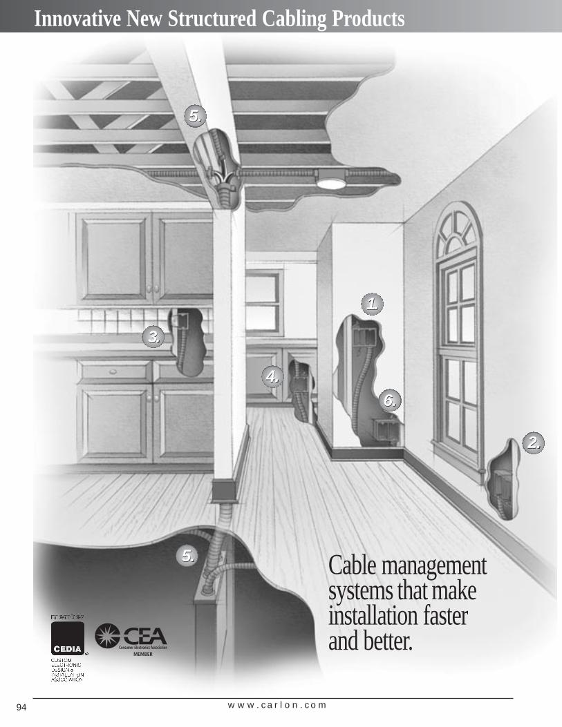
Innovative New Structured Cabling Products
Cable managementsystems that make installation faster and better.
w w w . c a r l o n . c o m94
5.5.
3.3.
5.5.
4.4.
1.1.
6.6.
2.2.
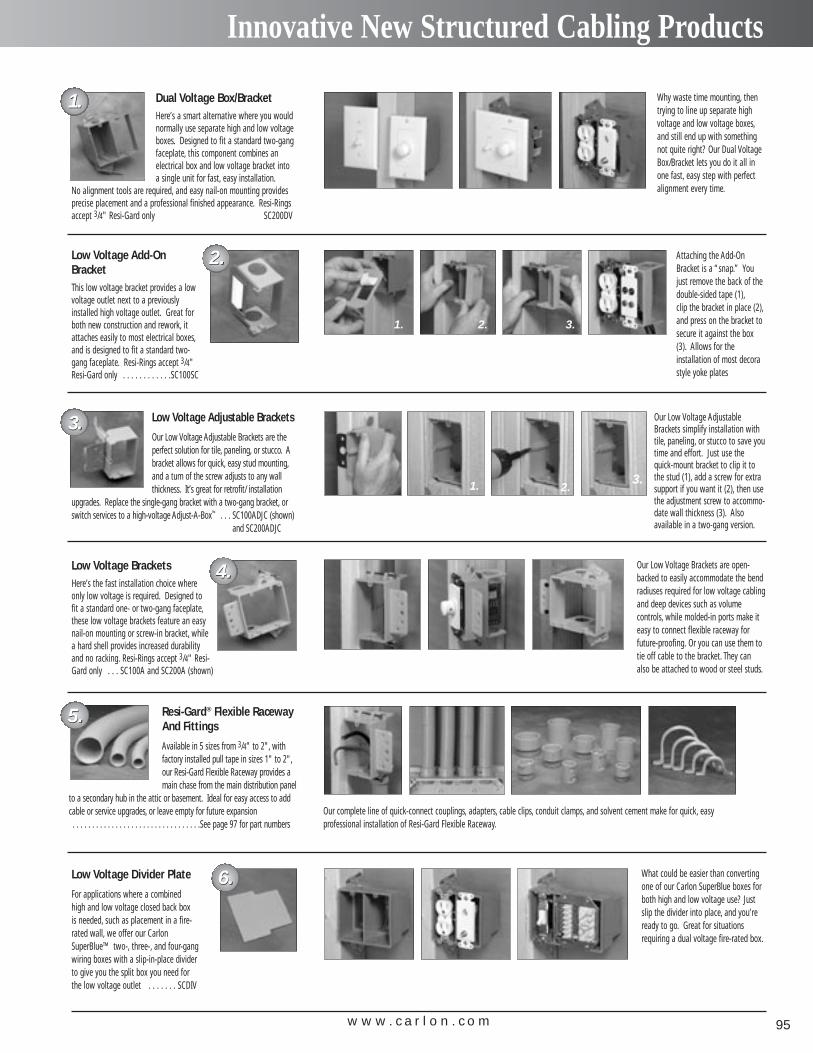
w w w . c a r l o n . c o m 95
Innovative New Structured Cabling Products
Dual Voltage Box/BracketHere’s a smart alternative where you wouldnormally use separate high and low voltageboxes. Designed to fit a standard two-gangfaceplate, this component combines an electrical box and low voltage bracket intoa single unit for fast, easy installation.
No alignment tools are required, and easy nail-on mounting providesprecise placement and a professional finished appearance. Resi-Ringsaccept 3/4" Resi-Gard only SC200DV
Low Voltage Adjustable Brackets
Our Low Voltage Adjustable Brackets are theperfect solution for tile, paneling, or stucco. Abracket allows for quick, easy stud mounting,and a turn of the screw adjusts to any wallthickness. It’s great for retrofit/ installation
upgrades. Replace the single-gang bracket with a two-gang bracket, orswitch services to a high-voltage Adjust-A-Box™ . . . SC100ADJC (shown)
and SC200ADJC
Resi-Gard® Flexible RacewayAnd Fittings
Available in 5 sizes from 3/4" to 2", withfactory installed pull tape in sizes 1" to 2",our Resi-Gard Flexible Raceway provides amain chase from the main distribution panel
to a secondary hub in the attic or basement. Ideal for easy access to addcable or service upgrades, or leave empty for future expansion . . . . . . . . . . . . . . . . . . . . . . . . . . . . . . . . .See page 97 for part numbers
Low Voltage Add-OnBracketThis low voltage bracket provides a lowvoltage outlet next to a previouslyinstalled high voltage outlet. Great forboth new construction and rework, itattaches easily to most electrical boxes,and is designed to fit a standard two-gang faceplate. Resi-Rings accept 3/4"Resi-Gard only . . . . . . . . . . . .SC100SC
Low Voltage BracketsHere’s the fast installation choice whereonly low voltage is required. Designed tofit a standard one- or two-gang faceplate,these low voltage brackets feature an easynail-on mounting or screw-in bracket, whilea hard shell provides increased durabilityand no racking. Resi-Rings accept 3/4" Resi-Gard only . . . SC100A and SC200A (shown)
Low Voltage Divider Plate
For applications where a combined high and low voltage closed back box is needed, such as placement in a fire-rated wall, we offer our CarlonSuperBlue™ two-, three-, and four-gangwiring boxes with a slip-in-place dividerto give you the split box you need forthe low voltage outlet . . . . . . . SCDIV
Why waste time mounting, thentrying to line up separate highvoltage and low voltage boxes,and still end up with somethingnot quite right? Our Dual VoltageBox/Bracket lets you do it all inone fast, easy step with perfectalignment every time.
Attaching the Add-OnBracket is a “snap.” Youjust remove the back of thedouble-sided tape (1),clip the bracket in place (2),and press on the bracket tosecure it against the box(3). Allows for the installation of most decorastyle yoke plates
Our Low Voltage Brackets are open-backed to easily accommodate the bendradiuses required for low voltage cablingand deep devices such as volume controls, while molded-in ports make iteasy to connect flexible raceway forfuture-proofing. Or you can use them totie off cable to the bracket. They canalso be attached to wood or steel studs.
What could be easier than convertingone of our Carlon SuperBlue boxes forboth high and low voltage use? Justslip the divider into place, and you’reready to go. Great for situationsrequiring a dual voltage fire-rated box.
Our Low Voltage AdjustableBrackets simplify installation withtile, paneling, or stucco to save youtime and effort. Just use thequick-mount bracket to clip it tothe stud (1), add a screw for extrasupport if you want it (2), then usethe adjustment screw to accommo-date wall thickness (3). Also available in a two-gang version.
1. 2. 3.
Our complete line of quick-connect couplings, adapters, cable clips, conduit clamps, and solvent cement make for quick, easy professional installation of Resi-Gard Flexible Raceway.
1. 2.3.
1.1.
2.2.
3.3.
4.4.
5.5.
6.6.
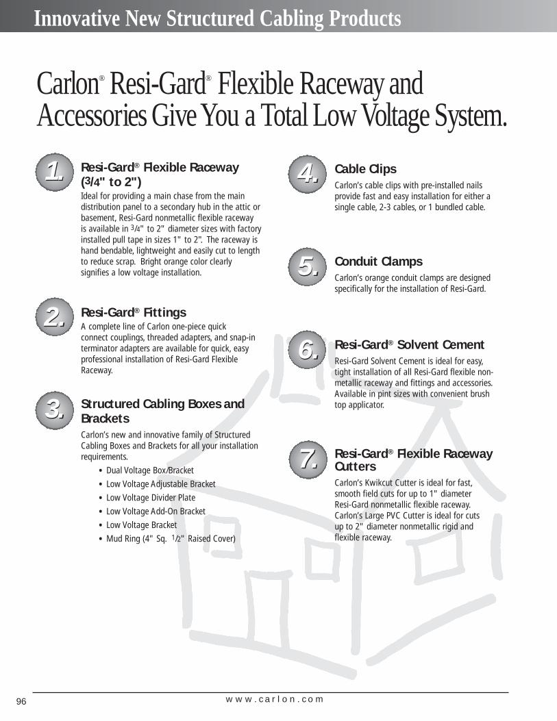
w w w . c a r l o n . c o m96
Innovative New Structured Cabling Products
1.1.
2.2.6.6.
5.5.
3.3.
4.4.
7.7.
Carlon® Resi-Gard® Flexible Raceway andAccessories GiveYou a Total Low Voltage System.
Resi-Gard® FittingsA complete line of Carlon one-piece quick connect couplings, threaded adapters, and snap-in terminator adapters are available for quick, easyprofessional installation of Resi-Gard FlexibleRaceway.
Resi-Gard® Flexible Raceway(3/4" to 2")Ideal for providing a main chase from the main distribution panel to a secondary hub in the attic orbasement, Resi-Gard nonmetallic flexible racewayis available in 3/4" to 2" diameter sizes with factoryinstalled pull tape in sizes 1" to 2". The raceway ishand bendable, lightweight and easily cut to lengthto reduce scrap. Bright orange color clearly signifies a low voltage installation.
Structured Cabling Boxes andBracketsCarlon’s new and innovative family of StructuredCabling Boxes and Brackets for all your installationrequirements.
• Dual Voltage Box/Bracket
• Low Voltage Adjustable Bracket
• Low Voltage Divider Plate
• Low Voltage Add-On Bracket
• Low Voltage Bracket
• Mud Ring (4" Sq. 1/2" Raised Cover)
Cable ClipsCarlon’s cable clips with pre-installed nails provide fast and easy installation for either asingle cable, 2-3 cables, or 1 bundled cable.
Conduit ClampsCarlon’s orange conduit clamps are designedspecifically for the installation of Resi-Gard.
Resi-Gard® Solvent Cement Resi-Gard Solvent Cement is ideal for easy,tight installation of all Resi-Gard flexible non-metallic raceway and fittings and accessories.Available in pint sizes with convenient brushtop applicator.
Resi-Gard® Flexible RacewayCuttersCarlon’s Kwikcut Cutter is ideal for fast,smooth field cuts for up to 1" diameter Resi-Gard nonmetallic flexible raceway.Carlon’s Large PVC Cutter is ideal for cuts up to 2" diameter nonmetallic rigid and flexible raceway.
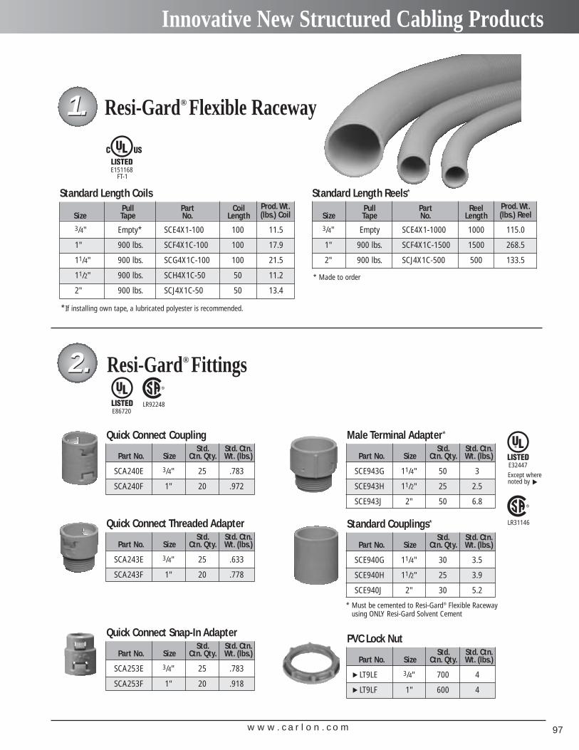
w w w . c a r l o n . c o m 97
Innovative New Structured Cabling Products
Resi-Gard® Fittings
Std. Std. Ctn.Part No. Size Ctn. Qty. Wt. (lbs.)
SCA240E 3/4" 25 .783
SCA240F 1" 20 .972
Quick Connect Coupling
Std. Std. Ctn.Part No. Size Ctn. Qty. Wt. (lbs.)
SCA243E 3/4" 25 .633
SCA243F 1" 20 .778
Quick Connect Threaded Adapter
Std. Std. Ctn.Part No. Size Ctn. Qty. Wt. (lbs.)
SCA253E 3/4" 25 .783
SCA253F 1" 20 .918
Quick Connect Snap-In Adapter
Std. Std. Ctn.Part No. Size Ctn. Qty. Wt. (lbs.)
SCE943G 11/4" 50 3
SCE943H 11/2" 25 2.5
SCE943J 2" 50 6.8
Male Terminal Adapter*
Std. Std. Ctn.Part No. Size Ctn. Qty. Wt. (lbs.)
SCE940G 11/4" 30 3.5
SCE940H 11/2" 25 3.9
SCE940J 2" 30 5.2
Standard Couplings*
Standard Length Coils
Resi-Gard® Flexible Raceway
Pull Part Coil Prod. Wt.Size Tape No. Length (lbs.) Coil
3/4" Empty* SCE4X1-100 100 11.5
1" 900 lbs. SCF4X1C-100 100 17.9
11/4" 900 lbs. SCG4X1C-100 100 21.5
11/2" 900 lbs. SCH4X1C-50 50 11.2
2" 900 lbs. SCJ4X1C-50 50 13.4
1.1.
2.2.
* Must be cemented to Resi-Gard® Flexible Raceway using ONLY Resi-Gard Solvent Cement
E86720
E32447
E151168FT-1
Standard Length Reels*
Pull Part Reel Prod. Wt.Size Tape No. Length (lbs.) Reel
3/4" Empty SCE4X1-1000 1000 115.0
1" 900 lbs. SCF4X1C-1500 1500 268.5
2" 900 lbs. SCJ4X1C-500 500 133.5
LR92248
* Made to order
Except wherenoted by ▼
LR31146
*If installing own tape, a lubricated polyester is recommended.
Std. Std. Ctn.Part No. Size Ctn. Qty. Wt. (lbs.)
LT9LE 3/4" 700 4
LT9LF 1" 600 4
PVC Lock Nut
▼▼
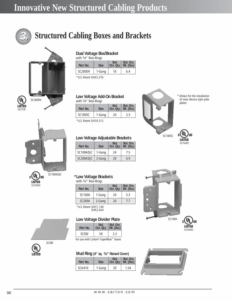
w w w . c a r l o n . c o m98
Innovative New Structured Cabling Products
Structured Cabling Boxes and Brackets
Std. Std. Ctn.Part No. Size Ctn. Qty. Wt. (lbs.)
SC100A 1-Gang 24 5.3
SC200A 2-Gang 24 7.7
*Low Voltage Bracketswith 3/4" Resi-Rings
Std. Std. Ctn.Part No. Size Ctn. Qty. Wt. (lbs.)
SC100ADJC 1-Gang 24 7.5
SC200ADJC 2-Gang 20 6.9
Low Voltage Adjustable Brackets
Std. Std. Ctn.Part No. Size Ctn. Qty. Wt. (lbs.)
SC200DV 1-Gang 16 6.4
Dual Voltage Box/Bracketwith 3/4" Resi-Rings
Std. Std. Ctn.Part No. Size Ctn. Qty. Wt. (lbs.)
SC100SC 1-Gang 24 2.3
Low Voltage Add-On Bracketwith 3/4" Resi-Rings
Std. Std. Ctn.Part No. Size Ctn. Qty. Wt. (lbs.)
SCA410 1-Gang 20 1.54
Mud Ring (4" sq. 1/2" Raised Cover)
Std. Std. Ctn.Part No. Ctn. Qty. Wt. (lbs.)
SCDIV 50 2.2
For use with Carlon® SuperBlue™ boxes
Low Voltage Divider Plate
3.3.
SC200DV
SC100ADJC
SC100A
SCDIV
SC100SC
E42728
E216492
E216492
E216492
*U.S. Patent D463,376
*U.S. Patent D459,312
*U.S. Patent D457,140D462,664
* Allows for the installationof most decora style yokeplates
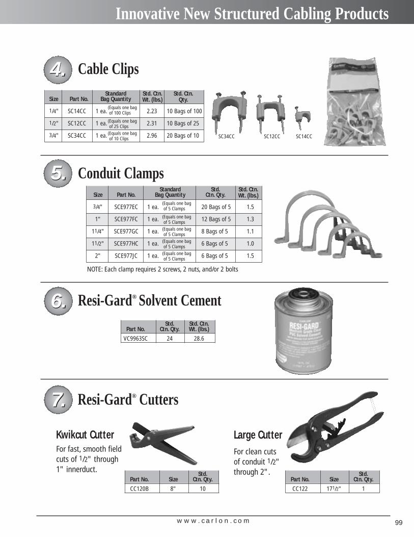
w w w . c a r l o n . c o m 99
Innovative New Structured Cabling Products
Resi-Gard® Solvent Cement Std. Std. Ctn.
Part No. Ctn. Qty. Wt. (lbs.)
VC9963SC 24 28.6
Resi-Gard® Cutters
Std.Part No. Size Ctn. Qty.
CC120B 8" 10
Std.Part No. Size Ctn. Qty.
CC122 171/2" 1
Cable ClipsStandard Std. Ctn. Std. Ctn.
Size Part No. Bag Quantity Wt. (lbs.) Qty.
1/4" SC14CC 1 ea. 2.23 10 Bags of 100
1/2" SC12CC 1 ea. 2.31 10 Bags of 25
3/4" SC34CC 1 ea. 2.96 20 Bags of 10
Conduit ClampsStandard Std. Std. Ctn.
Size Part No. Bag Quantity Ctn. Qty. Wt. (lbs.)
3/4" SCE977EC 1 ea. 20 Bags of 5 1.5
1" SCE977FC 1 ea. 12 Bags of 5 1.3
11/4" SCE977GC 1 ea. 8 Bags of 5 1.1
11/2" SCE977HC 1 ea. 6 Bags of 5 1.0
2" SCE977JC 1 ea. 6 Bags of 5 1.5
4.4.
5.5.
6.6.
7.7.
For clean cutsof conduit 1/2"through 2".
For fast, smooth fieldcuts of 1/2" through1" innerduct.
Kwikcut Cutter Large Cutter
(Equals one bag of 100 Clips
(Equals one bag of 25 Clips
(Equals one bag of 10 Clips
(Equals one bag of 5 Clamps
(Equals one bag of 5 Clamps
(Equals one bag of 5 Clamps
(Equals one bag of 5 Clamps
(Equals one bag of 5 Clamps
NOTE: Each clamp requires 2 screws, 2 nuts, and/or 2 bolts
SC34CC SC12CC SC14CC

w w w . c a r l o n . c o m100
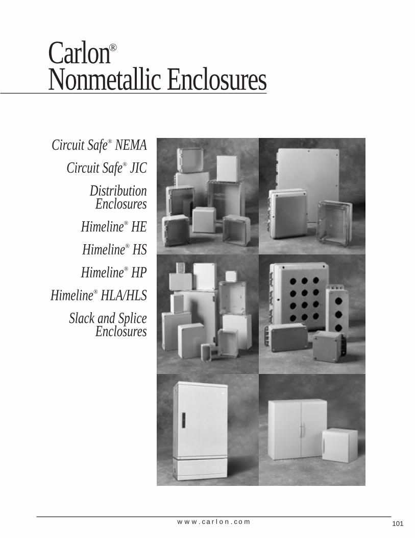
w w w . c a r l o n . c o m 101
Carlon®
Nonmetallic Enclosures
Circuit Safe® NEMA
Circuit Safe® JIC
DistributionEnclosures
Himeline® HE
Himeline® HS
Himeline® HP
Himeline® HLA/HLS
Slack and SpliceEnclosures
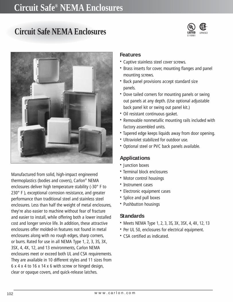
w w w . c a r l o n . c o m102
Circuit Safe® NEMA Enclosures
Circuit Safe NEMA Enclosures LR96563E110981
Manufactured from solid, high-impact engineered thermoplastics (bodies and covers), Carlon® NEMA enclosures deliver high temperature stability (-30° F to230° F ), exceptional corrosion resistance, and greaterperformance than traditional steel and stainless steelenclosures. Less than half the weight of metal enclosures,they‘re also easier to machine without fear of fractureand easier to install, while offering both a lower installedcost and longer service life. In addition, these attractiveenclosures offer molded-in features not found in metalenclosures along with no rough edges, sharp corners,or burrs. Rated for use in all NEMA Type 1, 2, 3, 3S, 3X,3SX, 4, 4X, 12, and 13 environments, Carlon NEMA enclosures meet or exceed both UL and CSA requirements.They are available in 10 different styles and 11 sizes from6 x 4 x 4 to 16 x 14 x 6 with screw or hinged design,clear or opaque covers, and quick-release latches.
Features• Captive stainless steel cover screws.• Brass inserts for cover, mounting flanges and panel
mounting screws.• Back panel provisions accept standard size
panels.• Dove tailed corners for mounting panels or swing
out panels at any depth. (Use optional adjustableback panel kit or swing out panel kit.)
• Oil resistant continuous gasket.• Removable nonmetallic mounting rails included with
factory assembled units.• Tapered edge keeps liquids away from door opening.• Ultraviolet stabilized for outdoor use.• Optional steel or PVC back panels available.
Applications• Junction boxes• Terminal block enclosures• Motor control housings• Instrument cases• Electronic equipment cases• Splice and pull boxes• Pushbutton housings
Standards• Meets NEMA Type 1, 2, 3, 3S, 3X, 3SX, 4, 4X, 12, 13• Per UL 50, enclosures for electrical equipment.• CSA certified as indicated.
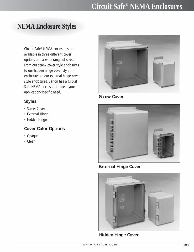
w w w . c a r l o n . c o m 103
Circuit Safe® NEMA Enclosures
NEMA Enclosure Styles
Screw Cover
Circuit Safe® NEMA enclosures areavailable in three different coveroptions and a wide range of sizes.From our screw cover style enclosuresto our hidden hinge cover style enclosures to our external hinge coverstyle enclosures, Carlon has a CircuitSafe NEMA enclosure to meet yourapplication-specific need.
Styles
• Screw Cover• External Hinge• Hidden Hinge
Cover Color Options
• Opaque• Clear
External Hinge Cover
Hidden Hinge Cover
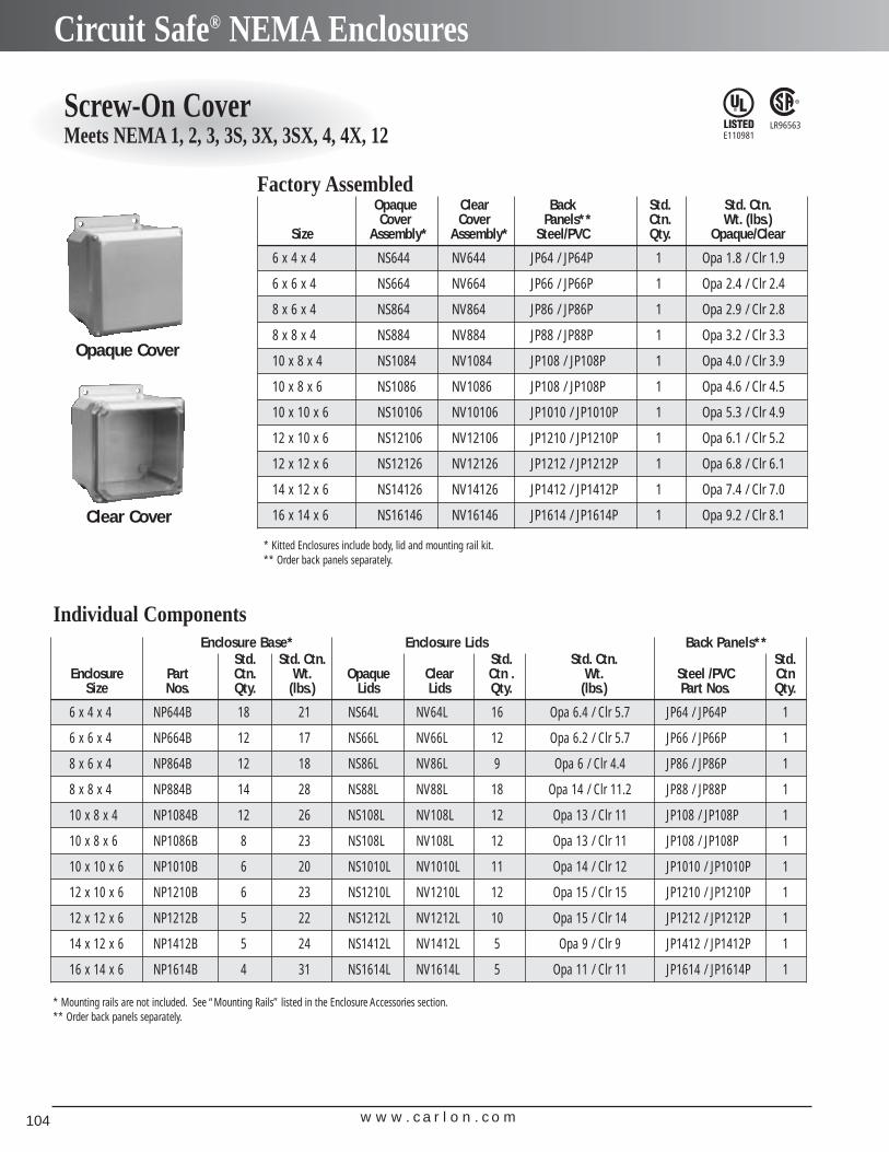
w w w . c a r l o n . c o m104
Circuit Safe® NEMA Enclosures
Screw-On CoverMeets NEMA 1, 2, 3, 3S, 3X, 3SX, 4, 4X, 12
LR96563E110981
Opaque Clear Back Std. Std. Ctn.Cover Cover Panels** Ctn. Wt. (lbs.)
Size Assembly* Assembly* Steel/PVC Qty. Opaque/Clear
6 x 4 x 4 NS644 NV644 JP64 / JP64P 1 Opa 1.8 / Clr 1.9
6 x 6 x 4 NS664 NV664 JP66 / JP66P 1 Opa 2.4 / Clr 2.4
8 x 6 x 4 NS864 NV864 JP86 / JP86P 1 Opa 2.9 / Clr 2.8
8 x 8 x 4 NS884 NV884 JP88 / JP88P 1 Opa 3.2 / Clr 3.3
10 x 8 x 4 NS1084 NV1084 JP108 / JP108P 1 Opa 4.0 / Clr 3.9
10 x 8 x 6 NS1086 NV1086 JP108 / JP108P 1 Opa 4.6 / Clr 4.5
10 x 10 x 6 NS10106 NV10106 JP1010 / JP1010P 1 Opa 5.3 / Clr 4.9
12 x 10 x 6 NS12106 NV12106 JP1210 / JP1210P 1 Opa 6.1 / Clr 5.2
12 x 12 x 6 NS12126 NV12126 JP1212 / JP1212P 1 Opa 6.8 / Clr 6.1
14 x 12 x 6 NS14126 NV14126 JP1412 / JP1412P 1 Opa 7.4 / Clr 7.0
16 x 14 x 6 NS16146 NV16146 JP1614 / JP1614P 1 Opa 9.2 / Clr 8.1
Enclosure Base* Enclosure Lids Back Panels**Std. Std. Ctn. Std. Std. Ctn. Std.
Enclosure Part Ctn. Wt. Opaque Clear Ctn . Wt. Steel /PVC CtnSize Nos. Qty. (lbs.) Lids Lids Qty. (lbs.) Part Nos. Qty.
6 x 4 x 4 NP644B 18 21 NS64L NV64L 16 Opa 6.4 / Clr 5.7 JP64 / JP64P 1
6 x 6 x 4 NP664B 12 17 NS66L NV66L 12 Opa 6.2 / Clr 5.7 JP66 / JP66P 1
8 x 6 x 4 NP864B 12 18 NS86L NV86L 9 Opa 6 / Clr 4.4 JP86 / JP86P 1
8 x 8 x 4 NP884B 14 28 NS88L NV88L 18 Opa 14 / Clr 11.2 JP88 / JP88P 1
10 x 8 x 4 NP1084B 12 26 NS108L NV108L 12 Opa 13 / Clr 11 JP108 / JP108P 1
10 x 8 x 6 NP1086B 8 23 NS108L NV108L 12 Opa 13 / Clr 11 JP108 / JP108P 1
10 x 10 x 6 NP1010B 6 20 NS1010L NV1010L 11 Opa 14 / Clr 12 JP1010 / JP1010P 1
12 x 10 x 6 NP1210B 6 23 NS1210L NV1210L 12 Opa 15 / Clr 15 JP1210 / JP1210P 1
12 x 12 x 6 NP1212B 5 22 NS1212L NV1212L 10 Opa 15 / Clr 14 JP1212 / JP1212P 1
14 x 12 x 6 NP1412B 5 24 NS1412L NV1412L 5 Opa 9 / Clr 9 JP1412 / JP1412P 1
16 x 14 x 6 NP1614B 4 31 NS1614L NV1614L 5 Opa 11 / Clr 11 JP1614 / JP1614P 1
Opaque Cover
Clear Cover
* Mounting rails are not included. See “Mounting Rails” listed in the Enclosure Accessories section.** Order back panels separately.
Factory Assembled
Individual Components
* Kitted Enclosures include body, lid and mounting rail kit.** Order back panels separately.
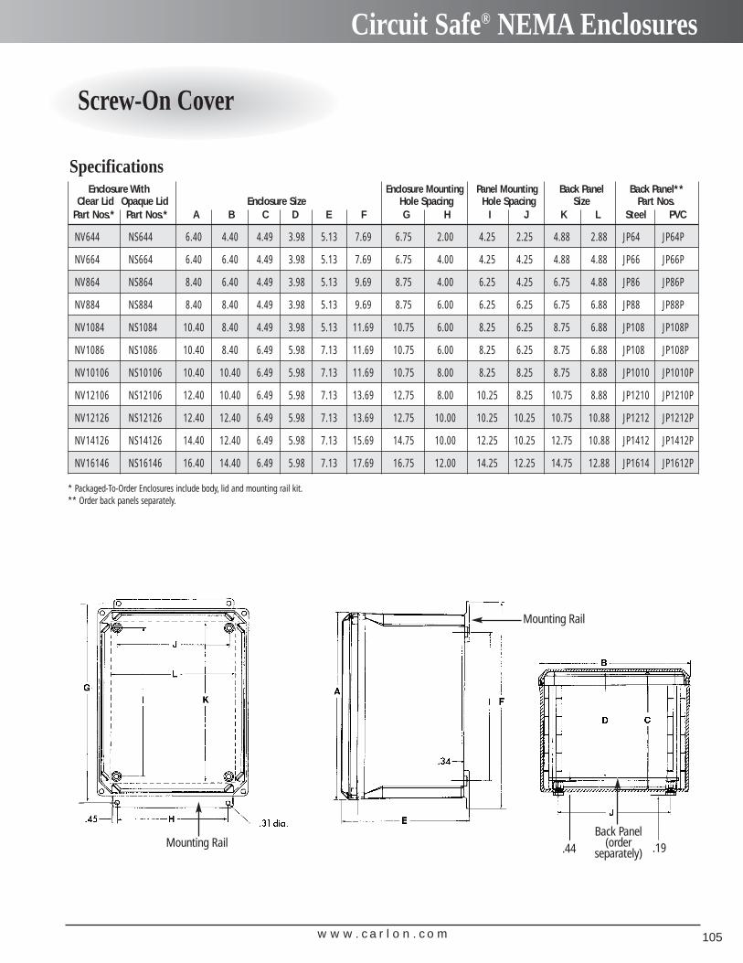
w w w . c a r l o n . c o m 105
Circuit Safe® NEMA Enclosures
Screw-On Cover
Enclosure With Enclosure Mounting Panel Mounting Back Panel Back Panel**Clear Lid Opaque Lid Enclosure Size Hole Spacing Hole Spacing Size Part Nos.
Part Nos.* Part Nos.* A B C D E F G H I J K L Steel PVC
NV644 NS644 6.40 4.40 4.49 3.98 5.13 7.69 6.75 2.00 4.25 2.25 4.88 2.88 JP64 JP64P
NV664 NS664 6.40 6.40 4.49 3.98 5.13 7.69 6.75 4.00 4.25 4.25 4.88 4.88 JP66 JP66P
NV864 NS864 8.40 6.40 4.49 3.98 5.13 9.69 8.75 4.00 6.25 4.25 6.75 4.88 JP86 JP86P
NV884 NS884 8.40 8.40 4.49 3.98 5.13 9.69 8.75 6.00 6.25 6.25 6.75 6.88 JP88 JP88P
NV1084 NS1084 10.40 8.40 4.49 3.98 5.13 11.69 10.75 6.00 8.25 6.25 8.75 6.88 JP108 JP108P
NV1086 NS1086 10.40 8.40 6.49 5.98 7.13 11.69 10.75 6.00 8.25 6.25 8.75 6.88 JP108 JP108P
NV10106 NS10106 10.40 10.40 6.49 5.98 7.13 11.69 10.75 8.00 8.25 8.25 8.75 8.88 JP1010 JP1010P
NV12106 NS12106 12.40 10.40 6.49 5.98 7.13 13.69 12.75 8.00 10.25 8.25 10.75 8.88 JP1210 JP1210P
NV12126 NS12126 12.40 12.40 6.49 5.98 7.13 13.69 12.75 10.00 10.25 10.25 10.75 10.88 JP1212 JP1212P
NV14126 NS14126 14.40 12.40 6.49 5.98 7.13 15.69 14.75 10.00 12.25 10.25 12.75 10.88 JP1412 JP1412P
NV16146 NS16146 16.40 14.40 6.49 5.98 7.13 17.69 16.75 12.00 14.25 12.25 14.75 12.88 JP1614 JP1612P
Specifications
* Packaged-To-Order Enclosures include body, lid and mounting rail kit.** Order back panels separately.
Mounting Rail
Mounting Rail
Back Panel(order
separately) .19.44
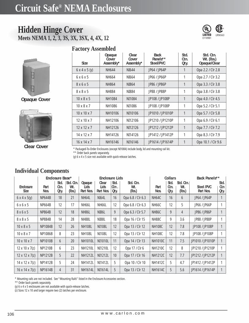
w w w . c a r l o n . c o m106
Circuit Safe® NEMA Enclosures
Hidden Hinge CoverMeets NEMA 1, 2, 3, 3S, 3X, 3SX, 4, 4X, 12
LR96563E110981
Opaque Clear Back Std. Std. Ctn.Cover Cover Panels** Ctn. Wt. (lbs.)
Size Assembly* Assembly* Steel/PVC Qty. Opaque/Clear
6 x 4 x 5 (y) NH644 NI644 JP64 / JP64P 1 Opa 2.2 / Clr 2.8
6 x 6 x 5 NH664 NI664 JP66 / JP66P 1 Opa 2.7 / Clr 3.2
8 x 6 x 5 NH864 NI864 JP86 / JP86P 1 Opa 3.3 / Clr 3.8
8 x 8 x 5 NH884 NI884 JP88 / JP88P 1 Opa 3.8 / Clr 3.8
10 x 8 x 5 NH1084 NI1084 JP108 / JP108P 1 Opa 4.0 / Clr 4.5
10 x 8 x 7 NH1086 NI1086 JP108 / JP108P 1 Opa 5.2 / Clr 5.1
10 x 10 x 7 NH10106 NI10106 JP1010 / JP1010P 1 Opa 5.7 / Clr 5.8
12 x 10 x 7 NH12106 NI12106 JP1210 / JP1210P 1 Opa 6.9 / Clr 6.1
12 x 12 x 7 NH12126 NI12126 JP1212 / JP1212P 1 Opa 7.7 / Clr 7.2
14 x 12 x 7 NH14126 NI14126 JP1412 / JP1412P 1 Opa 8.3 / Clr 7.9
16 x 14 x 7 NH16146 NI16146 JP1614 / JP1614P 1 Opa 10.1 / Clr 9.6
Enclosure Base* Enclosure Lids Collars Back Panels**Std. Std. Ctn. Opaque Clear Std. Std. Ctn. Std. Std. Ctn. Std.
Enclosure Part Ctn. Wt. Lids Lids Ctn . Wt. Part Ctn. Wt. Steel /PVC CtnSize Nos. Qty. (lbs.) Part Nos. Part Nos. Qty. (lbs.) Nos. Qty. (lbs.) Part Nos. Qty.
6 x 4 x 5(y) NP644B 18 21 NH64L NI64L 16 Opa 6.8 / Clr 6.3 NH64C 16 6 JP64 / JP64P 1
6 x 6 x 5 NP664B 12 17 NH66L NH66L 12 Opa 6.8 / Clr 6.3 NH66C 12 5 JP66 / JP66P 1
8 x 6 x 5 NP864B 12 18 NH86L NI86L 9 Opa 6.3 / Clr 5.7 NH86C 9 4 JP86 / JP86P 1
8 x 8 x 5 NP884B 14 28 NH88L NI88L 18 Opa 16 / Clr 15 NH88C 9 3.6 JP88 / JP88P 1
10 x 8 x 5 NP1084B 12 26 NH108L NI108L 12 Opa 13 / Clr 12 NH108C 12 7.8 JP108 / JP108P 1
10 x 8 x 7 NP1086B 8 23 NH108L NI108L 12 Opa 13 / Clr 12 NH108C 12 7.8 JP108 / JP108P 1
10 x 10 x 7 NP1010B 6 20 NH1010L NI1010L 11 Opa 14 / Clr 13 NH1010C 11 7.5 JP1010 / JP1010P 1
12 x 10 x 7(z) NP1210B 6 23 NH1210L NI1210L 12 Opa 17 / Clr 6 NH1210C 12 8 JP1210 / JP1210P 1
12 x 12 x 7(z) NP1212B 5 22 NH1212L NI1212L 10 Opa 17 / Clr 16 NH1212C 12 7.7 JP1212 / JP1212P 1
14 x 12 x 7(z) NP1412B 5 24 NH1412L NI1412L 5 Opa 10 / Clr 10 NH1412C 5 4.7 JP1412 / JP1412P 1
16 x 14 x 7(z) NP1614B 4 31 NH1614L NI1614L 5 Opa 13 / Clr 12 NH1614C 5 5.6 JP1614 / JP1614P 1
Opaque Cover
Clear Cover
* Mounting rails are not included. See “Mounting Rails” listed in the Enclosure Accessories section.** Order back panels separately.(y) 6 x 4 x 5 enclosures are not available with quick-release latches.(z) Sizes 12 x 10 and larger require two (2) latches per enclosure.
Factory Assembled
Individual Components
* Packaged-To-Order Enclosures (except NI1084) include body, lid and mounting rail kit.** Order back panels separately.(y) 6 x 4 x 5 size not available with quick-release latches.
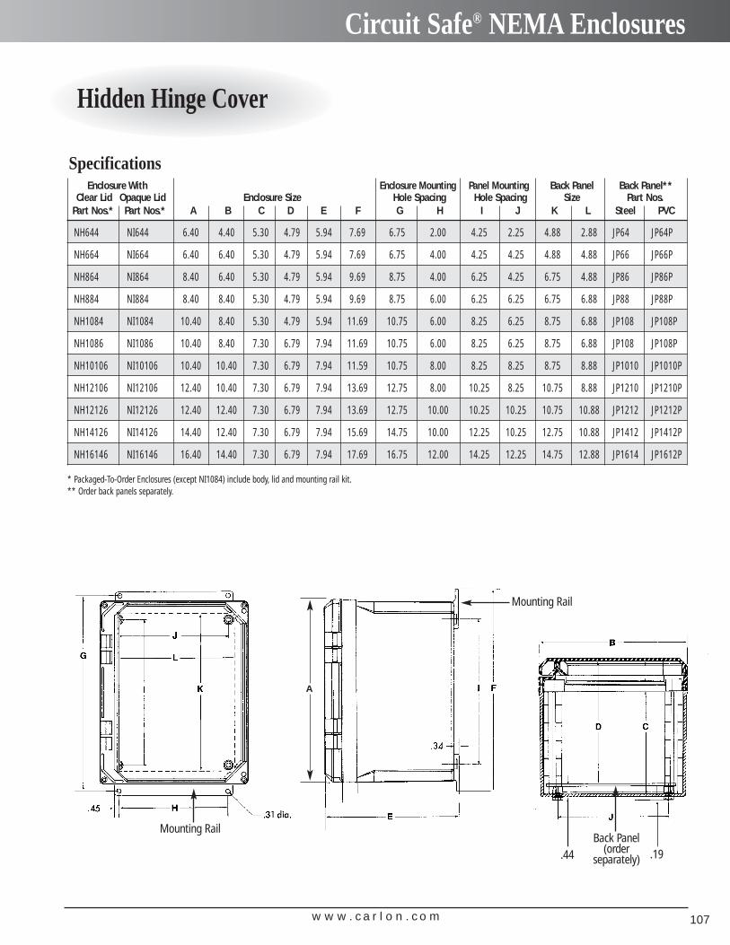
w w w . c a r l o n . c o m 107
Circuit Safe® NEMA Enclosures
Hidden Hinge Cover
Enclosure With Enclosure Mounting Panel Mounting Back Panel Back Panel**Clear Lid Opaque Lid Enclosure Size Hole Spacing Hole Spacing Size Part Nos.
Part Nos.* Part Nos.* A B C D E F G H I J K L Steel PVC
NH644 NI644 6.40 4.40 5.30 4.79 5.94 7.69 6.75 2.00 4.25 2.25 4.88 2.88 JP64 JP64P
NH664 NI664 6.40 6.40 5.30 4.79 5.94 7.69 6.75 4.00 4.25 4.25 4.88 4.88 JP66 JP66P
NH864 NI864 8.40 6.40 5.30 4.79 5.94 9.69 8.75 4.00 6.25 4.25 6.75 4.88 JP86 JP86P
NH884 NI884 8.40 8.40 5.30 4.79 5.94 9.69 8.75 6.00 6.25 6.25 6.75 6.88 JP88 JP88P
NH1084 NI1084 10.40 8.40 5.30 4.79 5.94 11.69 10.75 6.00 8.25 6.25 8.75 6.88 JP108 JP108P
NH1086 NI1086 10.40 8.40 7.30 6.79 7.94 11.69 10.75 6.00 8.25 6.25 8.75 6.88 JP108 JP108P
NH10106 NI10106 10.40 10.40 7.30 6.79 7.94 11.59 10.75 8.00 8.25 8.25 8.75 8.88 JP1010 JP1010P
NH12106 NI12106 12.40 10.40 7.30 6.79 7.94 13.69 12.75 8.00 10.25 8.25 10.75 8.88 JP1210 JP1210P
NH12126 NI12126 12.40 12.40 7.30 6.79 7.94 13.69 12.75 10.00 10.25 10.25 10.75 10.88 JP1212 JP1212P
NH14126 NI14126 14.40 12.40 7.30 6.79 7.94 15.69 14.75 10.00 12.25 10.25 12.75 10.88 JP1412 JP1412P
NH16146 NI16146 16.40 14.40 7.30 6.79 7.94 17.69 16.75 12.00 14.25 12.25 14.75 12.88 JP1614 JP1612P
Specifications
* Packaged-To-Order Enclosures (except NI1084) include body, lid and mounting rail kit.** Order back panels separately.
Mounting Rail
A
Back Panel(order
separately) .19.44
Mounting Rail
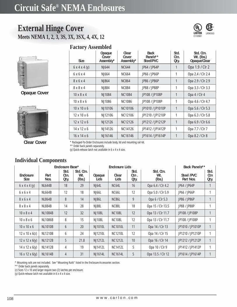
w w w . c a r l o n . c o m108
Circuit Safe® NEMA Enclosures
External Hinge CoverMeets NEMA 1, 2, 3, 3S, 3X, 3SX, 4, 4X, 12
LR96563E110981
Opaque Clear Back Std. Std. Ctn.Cover Cover Panels** Ctn. Wt. (lbs.)
Size Assembly* Assembly* Steel/PVC Qty. Opaque/Clear
6 x 4 x 4 (y) NJ644 NC644 JP64 / JP64P 1 Opa 1.9 / Clr 2
6 x 6 x 4 NJ664 NC664 JP66 / JP66P 1 Opa 2.4 / Clr 2.4
8 x 6 x 4 NJ864 NC864 JP86 / JP86P 1 Opa 2.9 / Clr 2.9
8 x 8 x 4 NJ884 NC884 JP88 / JP88P 1 Opa 3.3 / Clr 3.3
10 x 8 x 4 NJ1084 NC1084 JP108 / JP108P 1 Opa 4 / Clr 4
10 x 8 x 6 NJ1086 NC1086 JP108 / JP108P 1 Opa 4.6 / Clr 4.7
10 x 10 x 6 NJ10106 NC10106 JP1010 / JP1010P 1 Opa 5.6 / Clr 5.3
12 x 10 x 6 NJ12106 NC12106 JP1210 / JP1210P 1 Opa 6.3 / Clr 5.8
12 x 12 x 6 NJ12126 NC12126 JP1212 / JP1212P 1 Opa 6.9 / Clr 6.6
14 x 12 x 6 NJ14126 NC14126 JP1412 / JP1412P 1 Opa 7.7 / Clr 7
16 x 14 x 6 NJ16146 NC16146 JP1614 / JP1614P 1 Opa 8.2 / Clr 8
Enclosure Base* Enclosure Lids Back Panels**Std. Std. Ctn. Std. Std. Ctn. Std.
Enclosure Part Ctn. Wt. Opaque Clear Ctn . Wt. Steel /PVC CtnSize Nos. Qty. (lbs.) Lids Lids Qty. (lbs.) Part Nos. Qty.
6 x 4 x 4 (y) NL644B 18 29 NJ64L NC64L 16 Opa 6.4 / Clr 4.2 JP64 / JP64P 1
6 x 6 x 4 NL664B 12 18 NJ66L NC66L 12 Opa 5.0 / Clr 5.9 JP66 / JP66P 1
8 x 6 x 4 NL864B 8 14 NJ86L NC86L 9 Opa 6 / Clr 5.3 JP86 / JP86P 1
8 x 8 x 4 NL884B 14 28 NJ88L NC88L 18 Opa 15 / Clr 13.5 JP88 / JP88P 1
10 x 8 x 4 NL1084B 12 32 NJ108L NC108L 12 Opa 13 / Clr 11.7 JP108 / JP108P 1
10 x 8 x 6 NL1086B 8 15 NJ108L NC108L 12 Opa 13 / Clr 11.7 JP108 / JP108P 1
10 x 10 x 6 NL1010B 6 20 NJ1010L NC1010L 11 Opa 14 / Clr 13 JP1010 / JP1010P 1
12 x 10 x 6(z) NL1210B 6 24 NJ1210L NC1210L 12 Opa 14 / Clr 15 JP1210 / JP1210P 1
12 x 12 x 6(y) NL1212B 5 21.8 NJ1212L NC1212L 10 Opa 16 / Clr 14 JP1212 / JP1212P 1
14 x 12 x 6(y) NL1412B 4 19 NJ1412L NC1412L 5 Opa 10 / Clr 9 JP1412 / JP1412P 1
16 x 12 x 6(y) NL1614B 4 31 NJ1614L NC1614L 5 Opa 13.5 / Clr 12 JP1614 / JP1614P 1
Opaque Cover
Clear Cover
* Mounting rails are not included. See “Mounting Rails” listed in the Enclosure Accessories section.** Order back panels separately.(z) Sizes 12 x 10 and larger require two (2) latches per enclosure.(y) Quick-release latch not available in 6 x 4 x 4 size.
Factory Assembled
Individual Components
* Packaged-To-Order Enclosures include body, lid and mounting rail kit.** Order back panels separately.(y) Quick-release latch not available in 6 x 4 x 4 size.
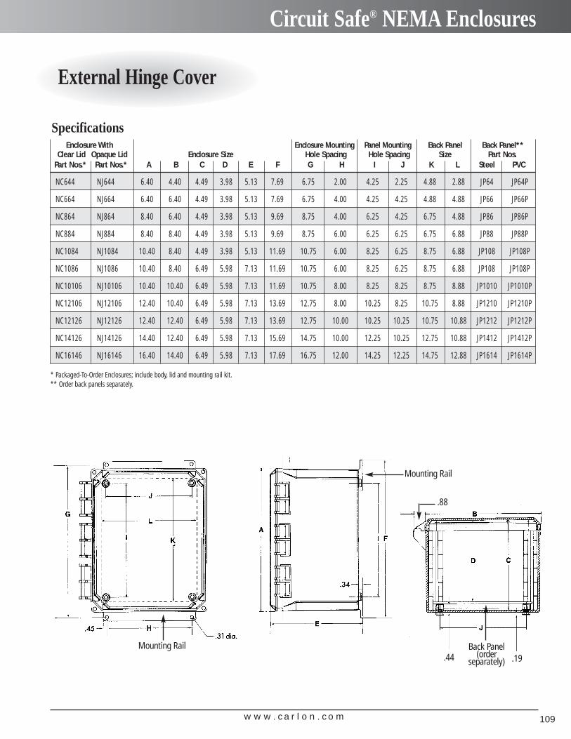
w w w . c a r l o n . c o m 109
Circuit Safe® NEMA Enclosures
External Hinge Cover
Enclosure With Enclosure Mounting Panel Mounting Back Panel Back Panel**Clear Lid Opaque Lid Enclosure Size Hole Spacing Hole Spacing Size Part Nos.
Part Nos.* Part Nos.* A B C D E F G H I J K L Steel PVC
NC644 NJ644 6.40 4.40 4.49 3.98 5.13 7.69 6.75 2.00 4.25 2.25 4.88 2.88 JP64 JP64P
NC664 NJ664 6.40 6.40 4.49 3.98 5.13 7.69 6.75 4.00 4.25 4.25 4.88 4.88 JP66 JP66P
NC864 NJ864 8.40 6.40 4.49 3.98 5.13 9.69 8.75 4.00 6.25 4.25 6.75 4.88 JP86 JP86P
NC884 NJ884 8.40 8.40 4.49 3.98 5.13 9.69 8.75 6.00 6.25 6.25 6.75 6.88 JP88 JP88P
NC1084 NJ1084 10.40 8.40 4.49 3.98 5.13 11.69 10.75 6.00 8.25 6.25 8.75 6.88 JP108 JP108P
NC1086 NJ1086 10.40 8.40 6.49 5.98 7.13 11.69 10.75 6.00 8.25 6.25 8.75 6.88 JP108 JP108P
NC10106 NJ10106 10.40 10.40 6.49 5.98 7.13 11.69 10.75 8.00 8.25 8.25 8.75 8.88 JP1010 JP1010P
NC12106 NJ12106 12.40 10.40 6.49 5.98 7.13 13.69 12.75 8.00 10.25 8.25 10.75 8.88 JP1210 JP1210P
NC12126 NJ12126 12.40 12.40 6.49 5.98 7.13 13.69 12.75 10.00 10.25 10.25 10.75 10.88 JP1212 JP1212P
NC14126 NJ14126 14.40 12.40 6.49 5.98 7.13 15.69 14.75 10.00 12.25 10.25 12.75 10.88 JP1412 JP1412P
NC16146 NJ16146 16.40 14.40 6.49 5.98 7.13 17.69 16.75 12.00 14.25 12.25 14.75 12.88 JP1614 JP1614P
Specifications
Mounting Rail
Mounting Rail
Back Panel(order
separately) .19.44
* Packaged-To-Order Enclosures; include body, lid and mounting rail kit.** Order back panels separately.
.88
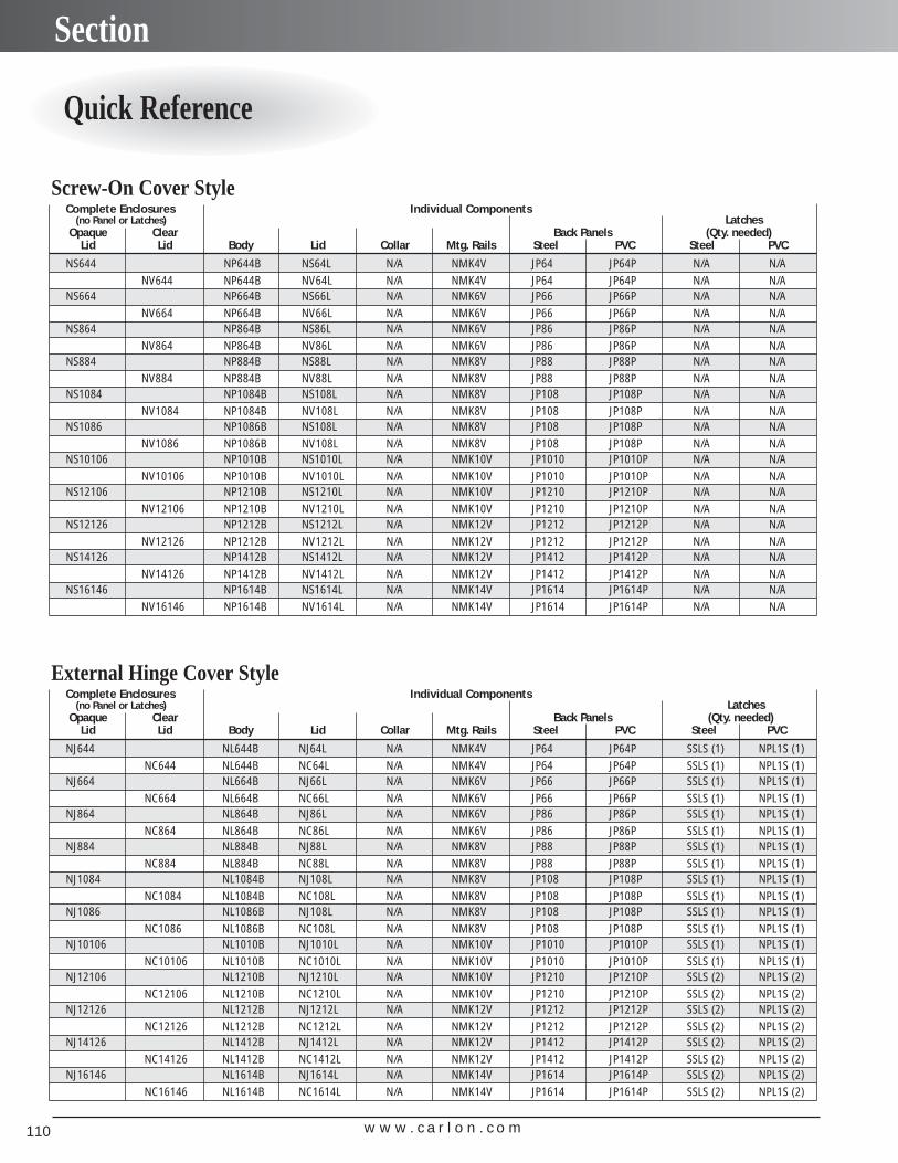
w w w . c a r l o n . c o m110
Section
Quick Reference
Complete Enclosures Individual Components (no Panel or Latches) Latches
Opaque Clear Back Panels (Qty. needed)Lid Lid Body Lid Collar Mtg. Rails Steel PVC Steel PVC
NS644 NP644B NS64L N/A NMK4V JP64 JP64P N/A N/ANV644 NP644B NV64L N/A NMK4V JP64 JP64P N/A N/A
NS664 NP664B NS66L N/A NMK6V JP66 JP66P N/A N/ANV664 NP664B NV66L N/A NMK6V JP66 JP66P N/A N/A
NS864 NP864B NS86L N/A NMK6V JP86 JP86P N/A N/ANV864 NP864B NV86L N/A NMK6V JP86 JP86P N/A N/A
NS884 NP884B NS88L N/A NMK8V JP88 JP88P N/A N/ANV884 NP884B NV88L N/A NMK8V JP88 JP88P N/A N/A
NS1084 NP1084B NS108L N/A NMK8V JP108 JP108P N/A N/ANV1084 NP1084B NV108L N/A NMK8V JP108 JP108P N/A N/A
NS1086 NP1086B NS108L N/A NMK8V JP108 JP108P N/A N/ANV1086 NP1086B NV108L N/A NMK8V JP108 JP108P N/A N/A
NS10106 NP1010B NS1010L N/A NMK10V JP1010 JP1010P N/A N/ANV10106 NP1010B NV1010L N/A NMK10V JP1010 JP1010P N/A N/A
NS12106 NP1210B NS1210L N/A NMK10V JP1210 JP1210P N/A N/ANV12106 NP1210B NV1210L N/A NMK10V JP1210 JP1210P N/A N/A
NS12126 NP1212B NS1212L N/A NMK12V JP1212 JP1212P N/A N/ANV12126 NP1212B NV1212L N/A NMK12V JP1212 JP1212P N/A N/A
NS14126 NP1412B NS1412L N/A NMK12V JP1412 JP1412P N/A N/ANV14126 NP1412B NV1412L N/A NMK12V JP1412 JP1412P N/A N/A
NS16146 NP1614B NS1614L N/A NMK14V JP1614 JP1614P N/A N/ANV16146 NP1614B NV1614L N/A NMK14V JP1614 JP1614P N/A N/A
Screw-On Cover Style
Complete Enclosures Individual Components (no Panel or Latches) Latches
Opaque Clear Back Panels (Qty. needed)Lid Lid Body Lid Collar Mtg. Rails Steel PVC Steel PVC
NJ644 NL644B NJ64L N/A NMK4V JP64 JP64P SSLS (1) NPL1S (1)NC644 NL644B NC64L N/A NMK4V JP64 JP64P SSLS (1) NPL1S (1)
NJ664 NL664B NJ66L N/A NMK6V JP66 JP66P SSLS (1) NPL1S (1)NC664 NL664B NC66L N/A NMK6V JP66 JP66P SSLS (1) NPL1S (1)
NJ864 NL864B NJ86L N/A NMK6V JP86 JP86P SSLS (1) NPL1S (1)NC864 NL864B NC86L N/A NMK6V JP86 JP86P SSLS (1) NPL1S (1)
NJ884 NL884B NJ88L N/A NMK8V JP88 JP88P SSLS (1) NPL1S (1)NC884 NL884B NC88L N/A NMK8V JP88 JP88P SSLS (1) NPL1S (1)
NJ1084 NL1084B NJ108L N/A NMK8V JP108 JP108P SSLS (1) NPL1S (1)NC1084 NL1084B NC108L N/A NMK8V JP108 JP108P SSLS (1) NPL1S (1)
NJ1086 NL1086B NJ108L N/A NMK8V JP108 JP108P SSLS (1) NPL1S (1)NC1086 NL1086B NC108L N/A NMK8V JP108 JP108P SSLS (1) NPL1S (1)
NJ10106 NL1010B NJ1010L N/A NMK10V JP1010 JP1010P SSLS (1) NPL1S (1)NC10106 NL1010B NC1010L N/A NMK10V JP1010 JP1010P SSLS (1) NPL1S (1)
NJ12106 NL1210B NJ1210L N/A NMK10V JP1210 JP1210P SSLS (2) NPL1S (2)NC12106 NL1210B NC1210L N/A NMK10V JP1210 JP1210P SSLS (2) NPL1S (2)
NJ12126 NL1212B NJ1212L N/A NMK12V JP1212 JP1212P SSLS (2) NPL1S (2)NC12126 NL1212B NC1212L N/A NMK12V JP1212 JP1212P SSLS (2) NPL1S (2)
NJ14126 NL1412B NJ1412L N/A NMK12V JP1412 JP1412P SSLS (2) NPL1S (2)NC14126 NL1412B NC1412L N/A NMK12V JP1412 JP1412P SSLS (2) NPL1S (2)
NJ16146 NL1614B NJ1614L N/A NMK14V JP1614 JP1614P SSLS (2) NPL1S (2)NC16146 NL1614B NC1614L N/A NMK14V JP1614 JP1614P SSLS (2) NPL1S (2)
External Hinge Cover Style
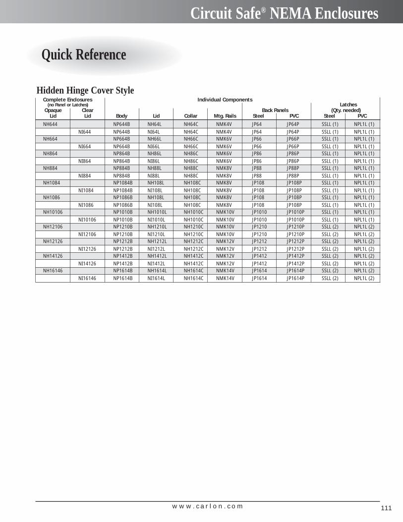
w w w . c a r l o n . c o m 111
Circuit Safe® NEMA Enclosures
Quick Reference
Complete Enclosures Individual Components (no Panel or Latches) Latches
Opaque Clear Back Panels (Qty. needed)Lid Lid Body Lid Collar Mtg. Rails Steel PVC Steel PVC
NH644 NP644B NH64L NH64C NMK4V JP64 JP64P SSLL (1) NPL1L (1)NI644 NP644B NI64L NH64C NMK4V JP64 JP64P SSLL (1) NPL1L (1)
NH664 NP664B NH66L NH66C NMK6V JP66 JP66P SSLL (1) NPL1L (1)NI664 NP664B NI66L NH66C NMK6V JP66 JP66P SSLL (1) NPL1L (1)
NH864 NP864B NH86L NH86C NMK6V JP86 JP86P SSLL (1) NPL1L (1)NI864 NP864B NI86L NH86C NMK6V JP86 JP86P SSLL (1) NPL1L (1)
NH884 NP884B NH88L NH88C NMK8V JP88 JP88P SSLL (1) NPL1L (1)NI884 NP884B NI88L NH88C NMK8V JP88 JP88P SSLL (1) NPL1L (1)
NH1084 NP1084B NH108L NH108C NMK8V JP108 JP108P SSLL (1) NPL1L (1)NI1084 NP1084B NI108L NH108C NMK8V JP108 JP108P SSLL (1) NPL1L (1)
NH1086 NP1086B NH108L NH108C NMK8V JP108 JP108P SSLL (1) NPL1L (1)NI1086 NP1086B NI108L NH108C NMK8V JP108 JP108P SSLL (1) NPL1L (1)
NH10106 NP1010B NH1010L NH1010C NMK10V JP1010 JP1010P SSLL (1) NPL1L (1)NI10106 NP1010B NI1010L NH1010C NMK10V JP1010 JP1010P SSLL (1) NPL1L (1)
NH12106 NP1210B NH1210L NH1210C NMK10V JP1210 JP1210P SSLL (2) NPL1L (2)NI12106 NP1210B NI1210L NH1210C NMK10V JP1210 JP1210P SSLL (2) NPL1L (2)
NH12126 NP1212B NH1212L NH1212C NMK12V JP1212 JP1212P SSLL (2) NPL1L (2)NI12126 NP1212B NI1212L NH1212C NMK12V JP1212 JP1212P SSLL (2) NPL1L (2)
NH14126 NP1412B NH1412L NH1412C NMK12V JP1412 JP1412P SSLL (2) NPL1L (2)NI14126 NP1412B NI1412L NH1412C NMK12V JP1412 JP1412P SSLL (2) NPL1L (2)
NH16146 NP1614B NH1614L NH1614C NMK14V JP1614 JP1614P SSLL (2) NPL1L (2)NI16146 NP1614B NI1614L NH1614C NMK14V JP1614 JP1614P SSLL (2) NPL1L (2)
Hidden Hinge Cover Style
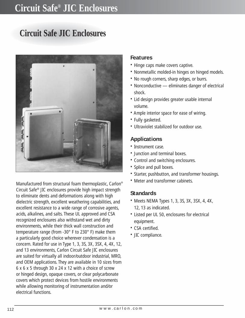
w w w . c a r l o n . c o m112
Circuit Safe® JIC Enclosures
Circuit Safe JIC Enclosures
Manufactured from structural foam thermoplastic, Carlon®
Circuit Safe® JIC enclosures provide high impact strengthto eliminate dents and deformations along with highdielectric strength, excellent weathering capabilities, andexcellent resistance to a wide range of corrosive agents,acids, alkalines, and salts. These UL approved and CSArecognized enclosures also withstand wet and dirty environments, while their thick wall construction and temperature range (from -30° F to 230° F) make them a particularly good choice wherever condensation is a concern. Rated for use in Type 1, 3, 3S, 3X, 3SX, 4, 4X, 12,and 13 environments, Carlon Circuit Safe JIC enclosuresare suited for virtually all indoor/outdoor industrial, MRO,and OEM applications. They are available in 10 sizes from 6 x 6 x 5 through 30 x 24 x 12 with a choice of screw or hinged design, opaque covers, or clear polycarbonate covers which protect devices from hostile environmentswhile allowing monitoring of instrumentation and/or electrical functions.
Features• Hinge caps make covers captive.• Nonmetallic molded-in hinges on hinged models.• No rough corners, sharp edges, or burrs.• Nonconductive — eliminates danger of electrical
shock.• Lid design provides greater usable internal
volume.• Ample interior space for ease of wiring.• Fully gasketed.• Ultraviolet stabilized for outdoor use.
Applications• Instrument case.• Junction and terminal boxes.• Control and switching enclosures.• Splice and pull boxes.• Starter, pushbutton, and transformer housings.• Meter and transformer cabinets.
Standards• Meets NEMA Types 1, 3, 3S, 3X, 3SX, 4, 4X,
12, 13 as indicated.• Listed per UL 50, enclosures for electrical
equipment.• CSA certified.• JIC compliance.
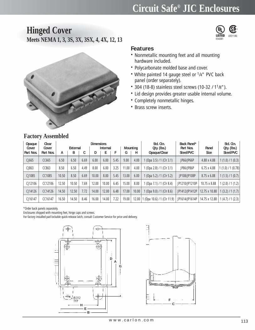
w w w . c a r l o n . c o m 113
Circuit Safe® JIC Enclosures
Hinged CoverMeets NEMA 1, 3, 3S, 3X, 3SX, 4, 4X, 12, 13
Opaque Clear Dimensions Std. Ctn. Back Panel* Std. Ctn.Cover Cover External Internal Mounting Qty. (lbs.) Part Nos. Panel Qty. (lbs.)
Part Nos. Part Nos. A B C D E F G H Opaque/Clear Steel/PVC Size Steel/PVC
CJ665 CC665 6.50 6.50 6.69 6.00 6.00 5.45 9.00 4.00 1 (Opa 3.5) / 1 (Clr 3.1) JP66/JP66P 4.88 x 4.88 1 (1.0) / 1 (0.3)
CJ863 CC863 8.50 6.50 4.49 8.00 6.00 3.25 11.00 4.00 1 (Opa 2.8) / 1 (Clr 3.1) JP86/JP86P 6.75 x 4.88 1 (1.0) / 1 (0.78)
CJ1085 CC1085 10.50 8.50 6.69 10.00 8.00 5.45 13.00 6.00 1 (Opa 5.2) / 1 (Clr 5.2) JP108/JP108P 8.75 x 6.88 1 (1.5) / 1 (0.7)
CJ12106 CC12106 12.50 10.50 7.69 12.00 10.00 6.45 15.00 8.00 1 (Opa 7.1) / 1 (Clr 8.4) JP1210/JP1210P 10.75 x 8.88 1 (2.0) / 1 (1.2)
CJ14126 CC14126 14.50 12.50 7.72 14.00 12.00 6.48 17.00 10.00 1 (Opa 9.0) / 1 (Clr 8.6) JP1412/JP1412P 12.75 x 10.88 1 (3.2) / 1 (1.7)
CJ16147 CC16147 16.50 14.50 8.46 16.00 14.00 7.22 19.00 12.00 1 (Opa 10.6) / 1 (Clr 11.9) JP1614/JP1614P 14.75 x 12.88 1 (4.7) / 1 (2.3)
Factory Assembled
*Order back panels separately.Enclosures shipped with mounting feet, hinge caps and screws.For factory installed pad lockable quick-release latch, consult Customer Service for price and delivery.
DA
G
HE
B
O.312TYP F
C
Features• Nonmetallic mounting feet and all mounting
hardware included.• Polycarbonate molded base and cover.• White painted 14 gauge steel or 1/4" PVC back
panel (order separately).• 304 (18-8) stainless steel screws (10-32 / 11/8").• Lid design provides greater usable internal volume.• Completely nonmetallic hinges.• Brass screw inserts.
LR31146E54381
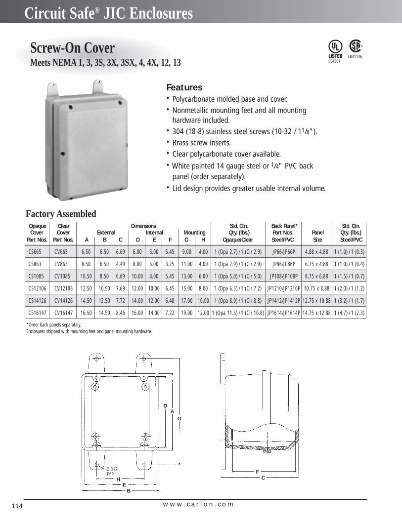
w w w . c a r l o n . c o m114
Circuit Safe® JIC Enclosures
Screw-On CoverMeets NEMA 1, 3, 3S, 3X, 3SX, 4, 4X, 12, 13
Opaque Clear Dimensions Std. Ctn. Back Panel* Std. Ctn.Cover Cover External Internal Mounting Qty. (lbs.) Part Nos. Panel Qty. (lbs.)
Part Nos. Part Nos. A B C D E F G H Opaque/Clear Steel/PVC Size Steel/PVC
CS665 CV665 6.50 6.50 6.69 6.00 6.00 5.45 9.00 4.00 1 (Opa 2.7) / 1 (Clr 2.9) JP66/JP66P 4.88 x 4.88 1 (1.0) / 1 (0.3)
CS863 CV863 8.50 6.50 4.49 8.00 6.00 3.25 11.00 4.00 1 (Opa 2.9) / 1 (Clr 2.9) JP86/JP86P 6.75 x 4.88 1 (1.0) / 1 (0.4)
CS1085 CV1085 10.50 8.50 6.69 10.00 8.00 5.45 13.00 6.00 1 (Opa 5.0) / 1 (Clr 5.0) JP108/JP108P 8.75 x 6.88 1 (1.5) / 1 (0.7)
CS12106 CV12106 12.50 10.50 7.69 12.00 10.00 6.45 15.00 8.00 1 (Opa 6.5) / 1 (Clr 7.2) JP1210/JP1210P 10.75 x 8.88 1 (2.0) / 1 (1.2)
CS14126 CV14126 14.50 12.50 7.72 14.00 12.00 6.48 17.00 10.00 1 (Opa 8.0) / 1 (Clr 8.8) JP1412/JP1412P 12.75 x 10.88 1 (3.2) / 1 (1.7)
CS16147 CV16147 16.50 14.50 8.46 16.00 14.00 7.22 19.00 12.00 1 (Opa 11.5) / 1 (Clr 10.8) JP1614/JP1614P 14.75 x 12.88 1 (4.7) / 1 (2.3)
Factory Assembled
*Order back panels separately.Enclosures shipped with mounting feet and panel mounting hardware.
Features• Polycarbonate molded base and cover.• Nonmetallic mounting feet and all mounting
hardware included.• 304 (18-8) stainless steel screws (10-32 / 11/8").• Brass screw inserts.• Clear polycarbonate cover available.• White painted 14 gauge steel or 1/4" PVC back
panel (order separately).• Lid design provides greater usable internal volume.
LR31146E54381
DA
G
HE
B
O.312TYP F
C
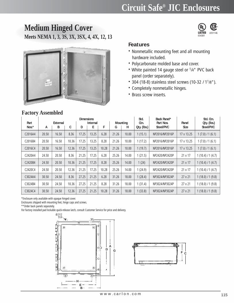
w w w . c a r l o n . c o m 115
Circuit Safe® JIC Enclosures
Medium Hinged CoverMeets NEMA 1, 3, 3S, 3X, 3SX, 4, 4X, 12, 13
Dimensions Std. Back Panel* Std. Ctn.Part External Internal Mounting Ctn. Part Nos. Panel Qty. (lbs.) Nos.* A B C D E F G H Qty. (lbs.) Steel/PVC Size Steel/PVC
C2016A4 20.50 16.50 8.36 17.25 13.25 6.28 21.26 10.00 1 (15.1) NP2016/NP2016P 17 x 13.25 1 (7.0) / 1 (6.1)
C2016B4 20.50 16.50 10.36 17.25 13.25 8.28 21.26 10.00 1 (17.2) NP2016/NP2016P 17 x 13.25 1 (7.0) / 1 (6.1)
C2016C4 20.50 16.50 12.36 17.25 13.25 10.28 21.26 10.00 1 (19.7) NP2016/NP2016P 17 x 13.25 1 (7.0) / 1 (6.1)
C2420A4 24.50 20.50 8.36 21.25 17.25 6.28 25.26 14.00 1 (21.5) NP2420/NP2420P 21 x 17 1 (10.4) / 1 (4.7)
C2420B4 24.50 20.50 10.36 21.25 17.25 8.28 25.26 14.00 1 (24) NP2420/NP2420P 21 x 17 1 (10.4) / 1 (4.7)
C2420C4 24.50 20.50 12.36 21.25 17.25 10.28 25.26 14.00 1 (24.9) NP2420/NP2420P 21 x 17 1 (10.4) / 1 (4.7)
C3024A4 30.50 24.50 8.36 27.25 21.25 6.28 31.26 18.00 1 (28.4) NP3024/NP3024P 27 x 21 1 (18.0) / 1 (9.8)
C3024B4 30.50 24.50 10.36 27.25 21.25 8.28 31.26 18.00 1 (31.4) NP3024/NP3024P 27 x 21 1 (18.0) / 1 (9.8)
C3024C4 30.50 24.50 12.36 27.25 21.25 10.28 31.26 18.00 1 (33.8) NP3024/NP3024P 27 x 21 1 (18.0) / 1 (9.8)
Factory Assembled
*Enclosure only available with opaque hinged cover.Enclosures shipped with mounting feet, hinge caps and screws.**Order back panels separately.For factory installed pad lockable quick-release latch, consult Customer Service for price and delivery.
Features• Nonmetallic mounting feet and all mounting
hardware included.• Polycarbonate molded base and cover.• White painted 14 gauge steel or 1/4" PVC back
panel (order separately).• 304 (18-8) stainless steel screws (10-32 / 11/8").• Completely nonmetallic hinges.• Brass screw inserts.
LR31146E54381
DA
G
O.312TYP
F C
H
BE
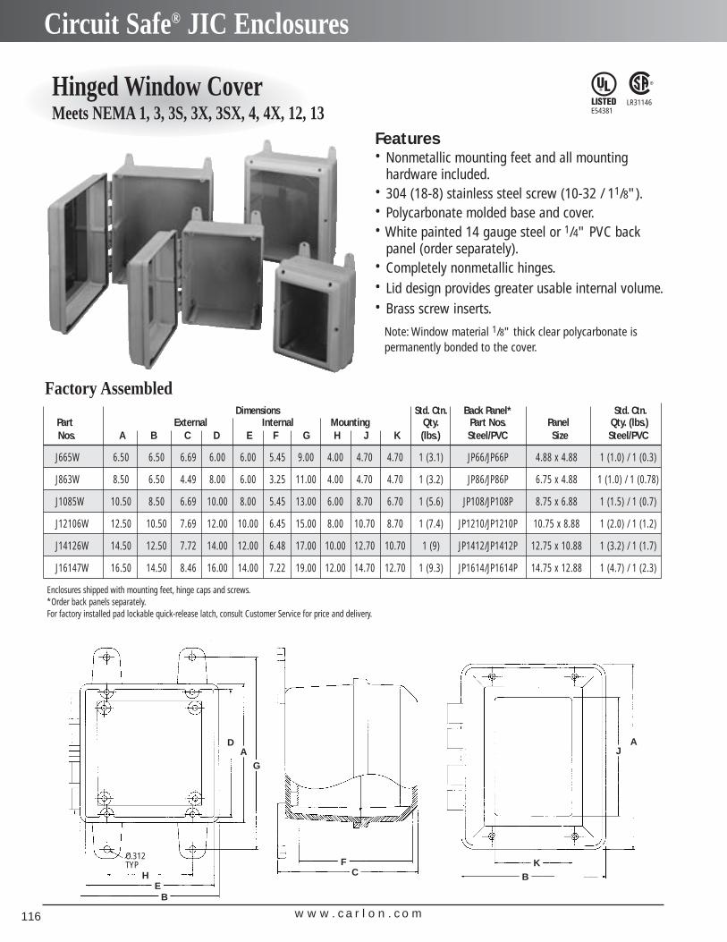
w w w . c a r l o n . c o m116
Circuit Safe® JIC Enclosures
Hinged Window CoverMeets NEMA 1, 3, 3S, 3X, 3SX, 4, 4X, 12, 13
Features• Nonmetallic mounting feet and all mounting
hardware included.• 304 (18-8) stainless steel screw (10-32 / 11/8").• Polycarbonate molded base and cover.• White painted 14 gauge steel or 1/4" PVC back
panel (order separately).• Completely nonmetallic hinges.• Lid design provides greater usable internal volume.• Brass screw inserts.
Note: Window material 1/8" thick clear polycarbonate is permanently bonded to the cover.
LR31146E54381
Dimensions Std. Ctn. Back Panel* Std. Ctn.Part External Internal Mounting Qty. Part Nos. Panel Qty. (lbs.) Nos. A B C D E F G H J K (lbs.) Steel/PVC Size Steel/PVC
J665W 6.50 6.50 6.69 6.00 6.00 5.45 9.00 4.00 4.70 4.70 1 (3.1) JP66/JP66P 4.88 x 4.88 1 (1.0) / 1 (0.3)
J863W 8.50 6.50 4.49 8.00 6.00 3.25 11.00 4.00 4.70 4.70 1 (3.2) JP86/JP86P 6.75 x 4.88 1 (1.0) / 1 (0.78)
J1085W 10.50 8.50 6.69 10.00 8.00 5.45 13.00 6.00 8.70 6.70 1 (5.6) JP108/JP108P 8.75 x 6.88 1 (1.5) / 1 (0.7)
J12106W 12.50 10.50 7.69 12.00 10.00 6.45 15.00 8.00 10.70 8.70 1 (7.4) JP1210/JP1210P 10.75 x 8.88 1 (2.0) / 1 (1.2)
J14126W 14.50 12.50 7.72 14.00 12.00 6.48 17.00 10.00 12.70 10.70 1 (9) JP1412/JP1412P 12.75 x 10.88 1 (3.2) / 1 (1.7)
J16147W 16.50 14.50 8.46 16.00 14.00 7.22 19.00 12.00 14.70 12.70 1 (9.3) JP1614/JP1614P 14.75 x 12.88 1 (4.7) / 1 (2.3)
Factory Assembled
Enclosures shipped with mounting feet, hinge caps and screws.*Order back panels separately.For factory installed pad lockable quick-release latch, consult Customer Service for price and delivery.
DA
G
HE
B
FC
O.312TYP
JA
KB
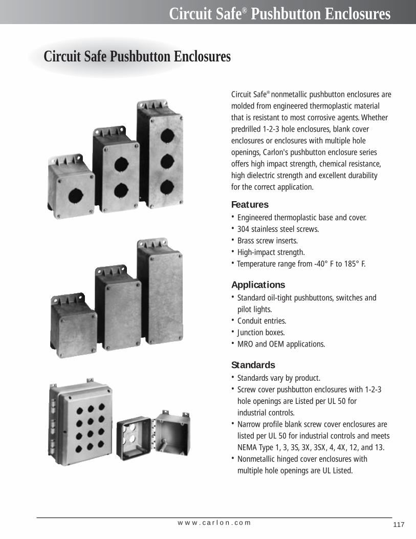
w w w . c a r l o n . c o m 117
Circuit Safe® Pushbutton Enclosures
Circuit Safe Pushbutton Enclosures
Circuit Safe® nonmetallic pushbutton enclosures aremolded from engineered thermoplastic materialthat is resistant to most corrosive agents. Whetherpredrilled 1-2-3 hole enclosures, blank cover enclosures or enclosures with multiple hole openings, Carlon's pushbutton enclosure seriesoffers high impact strength, chemical resistance,high dielectric strength and excellent durability for the correct application.
Features• Engineered thermoplastic base and cover.• 304 stainless steel screws.• Brass screw inserts.• High-impact strength.• Temperature range from -40° F to 185° F.
Applications• Standard oil-tight pushbuttons, switches and
pilot lights.• Conduit entries.• Junction boxes.• MRO and OEM applications.
Standards• Standards vary by product.• Screw cover pushbutton enclosures with 1-2-3
hole openings are Listed per UL 50 for industrial controls.
• Narrow profile blank screw cover enclosures arelisted per UL 50 for industrial controls and meetsNEMA Type 1, 3, 3S, 3X, 3SX, 4, 4X, 12, and 13.
• Nonmetallic hinged cover enclosures with multiple hole openings are UL Listed.
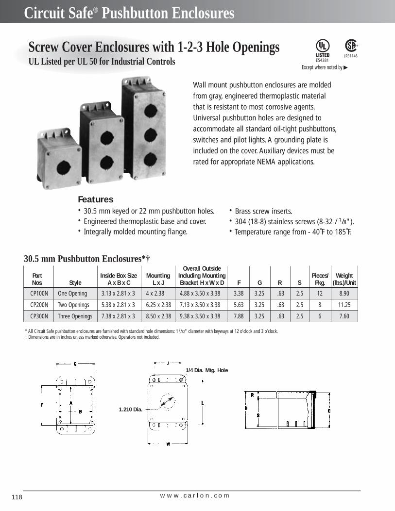
w w w . c a r l o n . c o m118
Circuit Safe® Pushbutton Enclosures
Screw Cover Enclosures with 1-2-3 Hole Openings UL Listed per UL 50 for Industrial Controls
30.5 mm Pushbutton Enclosures*†
LR31146
Features• 30.5 mm keyed or 22 mm pushbutton holes.• Engineered thermoplastic base and cover.• Integrally molded mounting flange.
Overall OutsidePart Inside Box Size Mounting Including Mounting Pieces/ WeightNos. Style A x B x C L x J Bracket H x W x D F G R S Pkg. (lbs.)/Unit
CP100N One Opening 3.13 x 2.81 x 3 4 x 2.38 4.88 x 3.50 x 3.38 3.38 3.25 .63 2.5 12 8.90
CP200N Two Openings 5.38 x 2.81 x 3 6.25 x 2.38 7.13 x 3.50 x 3.38 5.63 3.25 .63 2.5 8 11.25
CP300N Three Openings 7.38 x 2.81 x 3 8.50 x 2.38 9.38 x 3.50 x 3.38 7.88 3.25 .63 2.5 6 7.60
Wall mount pushbutton enclosures are molded from gray, engineered thermoplastic materialthat is resistant to most corrosive agents.Universal pushbutton holes are designed toaccommodate all standard oil-tight pushbuttons,switches and pilot lights. A grounding plate isincluded on the cover. Auxiliary devices must berated for appropriate NEMA applications.
• Brass screw inserts.• 304 (18-8) stainless screws (8-32 / 3/8").• Temperature range from - 40˚F to 185˚F.
E54381
Except where noted by �
1.210 Dia.
1/4 Dia. Mtg. Hole
* All Circuit Safe pushbutton enclosures are furnished with standard hole dimensions: 17/32" diameter with keyways at 12 o’clock and 3 o’clock.† Dimensions are in inches unless marked otherwise. Operators not included.
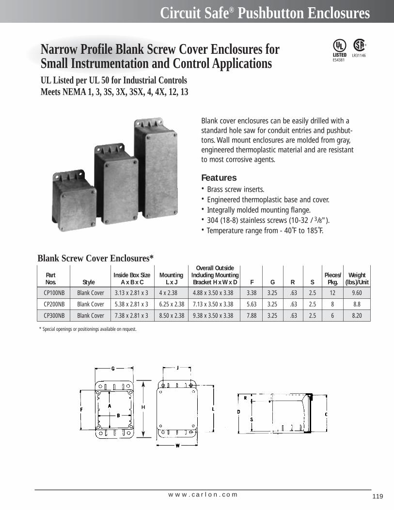
w w w . c a r l o n . c o m 119
Circuit Safe® Pushbutton Enclosures
Narrow Profile Blank Screw Cover Enclosures forSmall Instrumentation and Control ApplicationsUL Listed per UL 50 for Industrial ControlsMeets NEMA 1, 3, 3S, 3X, 3SX, 4, 4X, 12, 13
LR31146E54381
Blank cover enclosures can be easily drilled with astandard hole saw for conduit entries and pushbut-tons. Wall mount enclosures are molded from gray,engineered thermoplastic material and are resistantto most corrosive agents.
Features• Brass screw inserts.• Engineered thermoplastic base and cover.• Integrally molded mounting flange.• 304 (18-8) stainless screws (10-32 / 3/8").• Temperature range from - 40˚F to 185˚F.
Blank Screw Cover Enclosures*Overall Outside
Part Inside Box Size Mounting Including Mounting Pieces/ WeightNos. Style A x B x C L x J Bracket H x W x D F G R S Pkg. (lbs.)/Unit
CP100NB Blank Cover 3.13 x 2.81 x 3 4 x 2.38 4.88 x 3.50 x 3.38 3.38 3.25 .63 2.5 12 9.60
CP200NB Blank Cover 5.38 x 2.81 x 3 6.25 x 2.38 7.13 x 3.50 x 3.38 5.63 3.25 .63 2.5 8 8.8
CP300NB Blank Cover 7.38 x 2.81 x 3 8.50 x 2.38 9.38 x 3.50 x 3.38 7.88 3.25 .63 2.5 6 8.20
* Special openings or positionings available on request.
H
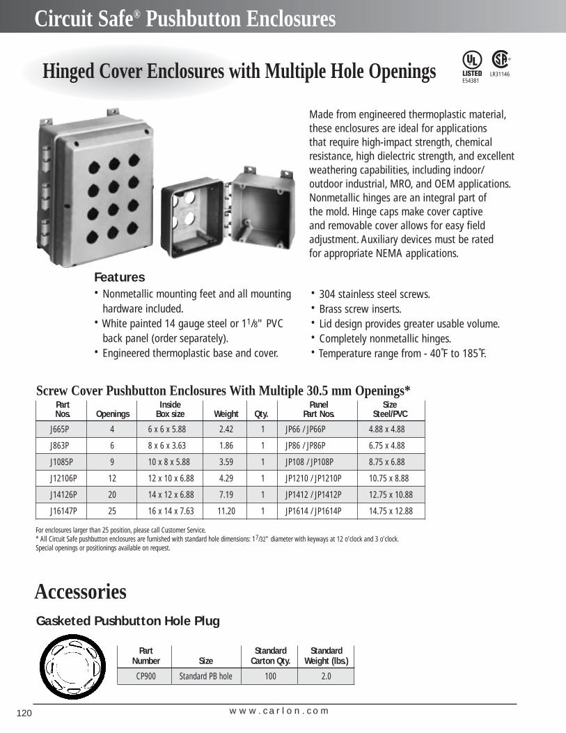
w w w . c a r l o n . c o m120
Circuit Safe® Pushbutton Enclosures
Hinged Cover Enclosures with Multiple Hole Openings
Screw Cover Pushbutton Enclosures With Multiple 30.5 mm Openings*
LR31146E54381
Features• Nonmetallic mounting feet and all mounting
hardware included.• White painted 14 gauge steel or 11/8" PVC
back panel (order separately).• Engineered thermoplastic base and cover.
Part Inside Panel SizeNos. Openings Box size Weight Qty. Part Nos. Steel/PVC
J665P 4 6 x 6 x 5.88 2.42 1 JP66 / JP66P 4.88 x 4.88
J863P 6 8 x 6 x 3.63 1.86 1 JP86 / JP86P 6.75 x 4.88
J1085P 9 10 x 8 x 5.88 3.59 1 JP108 / JP108P 8.75 x 6.88
J12106P 12 12 x 10 x 6.88 4.29 1 JP1210 / JP1210P 10.75 x 8.88
J14126P 20 14 x 12 x 6.88 7.19 1 JP1412 / JP1412P 12.75 x 10.88
J16147P 25 16 x 14 x 7.63 11.20 1 JP1614 / JP1614P 14.75 x 12.88
For enclosures larger than 25 position, please call Customer Service.* All Circuit Safe pushbutton enclosures are furnished with standard hole dimensions: 17/32" diameter with keyways at 12 o’clock and 3 o’clock.Special openings or positionings available on request.
Gasketed Pushbutton Hole Plug
Part Standard Standard Number Size Carton Qty. Weight (lbs.)
CP900 Standard PB hole 100 2.0
Accessories
Made from engineered thermoplastic material,these enclosures are ideal for applications that require high-impact strength, chemicalresistance, high dielectric strength, and excellentweathering capabilities, including indoor/outdoor industrial, MRO, and OEM applications.Nonmetallic hinges are an integral part of the mold. Hinge caps make cover captive and removable cover allows for easy field adjustment. Auxiliary devices must be rated for appropriate NEMA applications.
• 304 stainless steel screws.• Brass screw inserts.• Lid design provides greater usable volume.• Completely nonmetallic hinges.• Temperature range from - 40˚F to 185˚F.
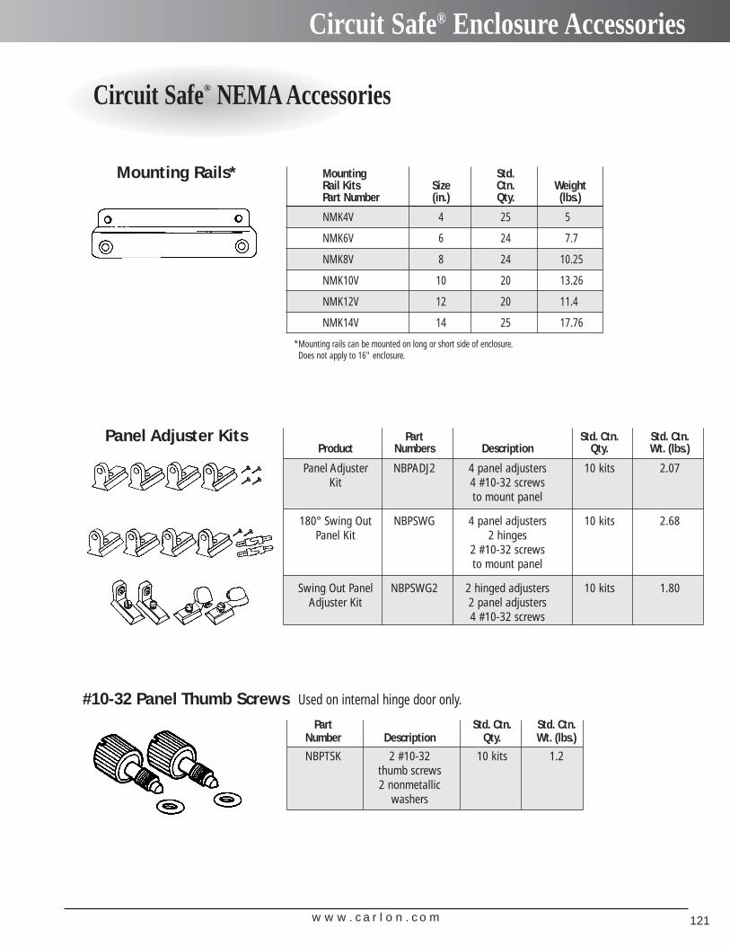
w w w . c a r l o n . c o m 121
Circuit Safe® Enclosure Accessories
Circuit Safe® NEMA Accessories
Part Std. Ctn. Std. Ctn.Product Numbers Description Qty. Wt. (lbs.)
Panel Adjuster NBPADJ2 4 panel adjusters 10 kits 2.07Kit 4 #10-32 screws
to mount panel
180° Swing Out NBPSWG 4 panel adjusters 10 kits 2.68Panel Kit 2 hinges
2 #10-32 screwsto mount panel
Swing Out Panel NBPSWG2 2 hinged adjusters 10 kits 1.80Adjuster Kit 2 panel adjusters
4 #10-32 screws
Panel Adjuster Kits
Mounting Rails*
*Mounting rails can be mounted on long or short side of enclosure.Does not apply to 16" enclosure.
#10-32 Panel Thumb Screws Used on internal hinge door only.
Part Std. Ctn. Std. Ctn.Number Description Qty. Wt. (lbs.)
NBPTSK 2 #10-32 10 kits 1.2thumb screws2 nonmetallic
washers
Mounting Std.Rail Kits Size Ctn. WeightPart Number (in.) Qty. (lbs.)
NMK4V 4 25 5
NMK6V 6 24 7.7
NMK8V 8 24 10.25
NMK10V 10 20 13.26
NMK12V 12 20 11.4
NMK14V 14 25 17.76
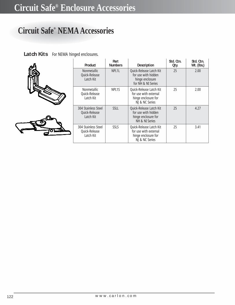
w w w . c a r l o n . c o m122
Circuit Safe® Enclosure Accessories
Circuit Safe® NEMA Accessories
Part Std. Ctn. Std. Ctn.Product Numbers Description Qty. Wt. (lbs.)
Nonmetallic NPL1L Quick-Release Latch Kit 25 2.00Quick-Release for use with hidden
Latch Kit hinge enclosurefor NH & NI Series
Nonmetallic NPL1S Quick-Release Latch Kit 25 2.00Quick-Release for use with external
Latch Kit hinge enclosure forNJ & NC Series
304 Stainless Steel SSLL Quick-Release Latch Kit 25 4.27Quick-Release for use with hidden
Latch Kit hinge enclosure forNH & NI Series
304 Stainless Steel SSLS Quick-Release Latch Kit 25 3.41Quick-Release for use with external
Latch Kit hinge enclosure forNJ & NC Series
Latch Kits For NEMA hinged enclosures.
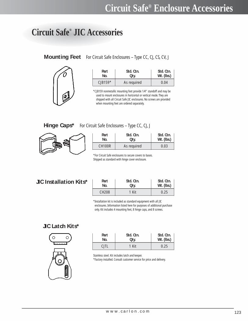
w w w . c a r l o n . c o m 123
Circuit Safe® Enclosure Accessories
Circuit Safe® JIC Accessories
Mounting Feet For Circuit Safe Enclosures – Type CC, CJ, CS, CV, J
Part Std. Ctn. Std. Ctn.No. Qty. Wt. (lbs.)
CJB159* As required 0.04
*CJB159 nonmetallic mounting feet provide 1/4" standoff and may beused to mount enclosures in horizontal or vertical mode. They areshipped with all Circuit Safe JIC enclosures. No screws are providedwhen mounting feet are ordered separately.
Hinge Caps* For Circuit Safe Enclosures – Type CC, CJ, J
Part Std. Ctn. Std. Ctn.No. Qty. Wt. (lbs.)
CH100R As required 0.03
*For Circuit Safe enclosures to secure covers to bases.Shipped as standard with hinge cover enclosure.
JIC Installation Kits* Part Std. Ctn. Std. Ctn.No. Qty. Wt. (lbs.)
CH208 1 Kit 0.25
*Installation kit is included as standard equipment with all JIC enclosures. Information listed here for purposes of additional purchaseonly. Kit includes 4 mounting feet, 8 hinge caps, and 8 screws.
JIC Latch Kits*Part Std. Ctn. Std. Ctn.No. Qty. Wt. (lbs.)
CJTL 1 Kit 0.25
Stainless steel. Kit includes latch and keeper.*Factory installed. Consult customer service for price and delivery.
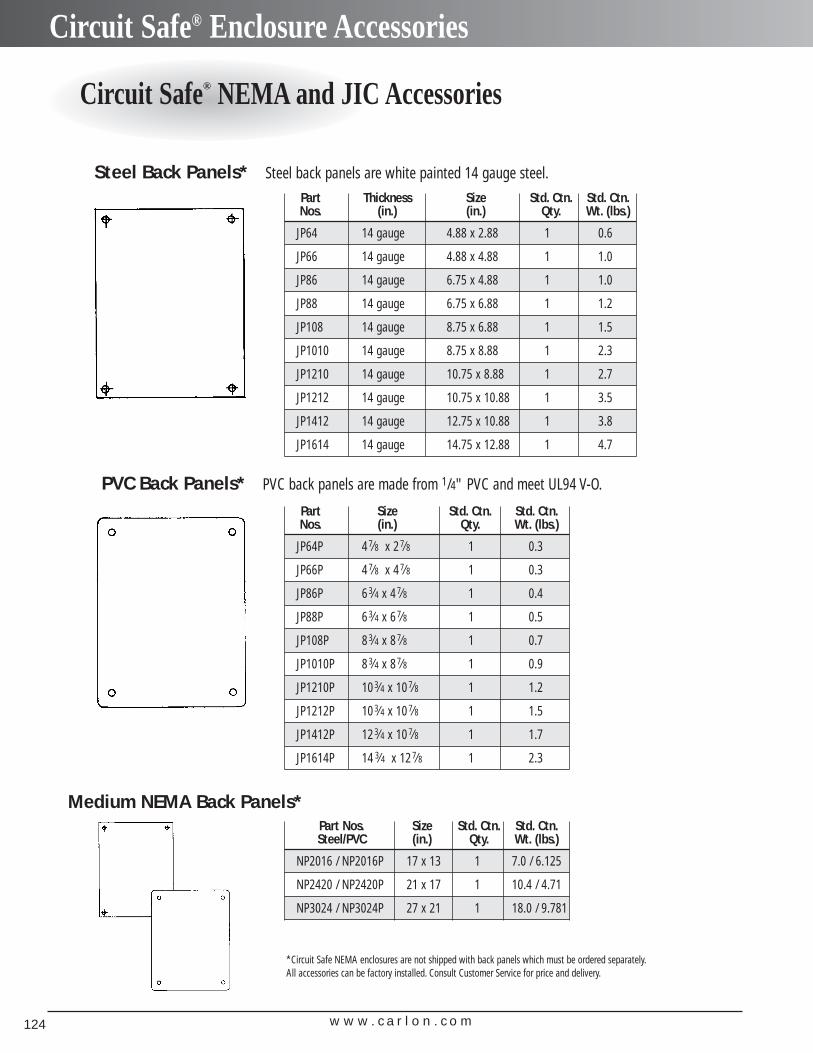
w w w . c a r l o n . c o m124
Circuit Safe® Enclosure Accessories
Circuit Safe® NEMA and JIC Accessories
Steel Back Panels* Steel back panels are white painted 14 gauge steel.
Part Thickness Size Std. Ctn. Std. Ctn.Nos. (in.) (in.) Qty. Wt. (lbs.)
JP64 14 gauge 4.88 x 2.88 1 0.6
JP66 14 gauge 4.88 x 4.88 1 1.0
JP86 14 gauge 6.75 x 4.88 1 1.0
JP88 14 gauge 6.75 x 6.88 1 1.2
JP108 14 gauge 8.75 x 6.88 1 1.5
JP1010 14 gauge 8.75 x 8.88 1 2.3
JP1210 14 gauge 10.75 x 8.88 1 2.7
JP1212 14 gauge 10.75 x 10.88 1 3.5
JP1412 14 gauge 12.75 x 10.88 1 3.8
JP1614 14 gauge 14.75 x 12.88 1 4.7
PVC Back Panels* PVC back panels are made from 1/4" PVC and meet UL94 V-O.
Part Size Std. Ctn. Std. Ctn.Nos. (in.) Qty. Wt. (lbs.)
JP64P 47⁄8 x 27⁄8 1 0.3
JP66P 47⁄8 x 47⁄8 1 0.3
JP86P 63⁄4 x 47⁄8 1 0.4
JP88P 63⁄4 x 67⁄8 1 0.5
JP108P 83⁄4 x 87⁄8 1 0.7
JP1010P 83⁄4 x 87⁄8 1 0.9
JP1210P 103⁄4 x 10⁷⁄8 1 1.2
JP1212P 103⁄4 x 10⁷⁄8 1 1.5
JP1412P 123⁄4 x 10⁷⁄8 1 1.7
JP1614P 14 3⁄4 x 127⁄8 1 2.3
Medium NEMA Back Panels*Part Nos. Size Std. Ctn. Std. Ctn.Steel/PVC (in.) Qty. Wt. (lbs.)
NP2016 / NP2016P 17 x 13 1 7.0 / 6.125
NP2420 / NP2420P 21 x 17 1 10.4 / 4.71
NP3024 / NP3024P 27 x 21 1 18.0 / 9.781
*Circuit Safe NEMA enclosures are not shipped with back panels which must be ordered separately.All accessories can be factory installed. Consult Customer Service for price and delivery.
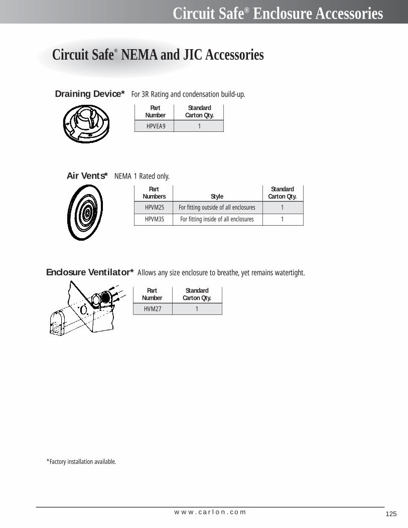
w w w . c a r l o n . c o m 125
Circuit Safe® Enclosure Accessories
Circuit Safe® NEMA and JIC Accessories
Draining Device* For 3R Rating and condensation build-up.
Air Vents* NEMA 1 Rated only.
Enclosure Ventilator* Allows any size enclosure to breathe, yet remains watertight.
Part Standard Number Carton Qty.
HPVEA9 1
Part Standard Number Carton Qty.
HVM27 1
Part Standard Numbers Style Carton Qty.
HPVM25 For fitting outside of all enclosures 1
HPVM35 For fitting inside of all enclosures 1
*Factory installation available.
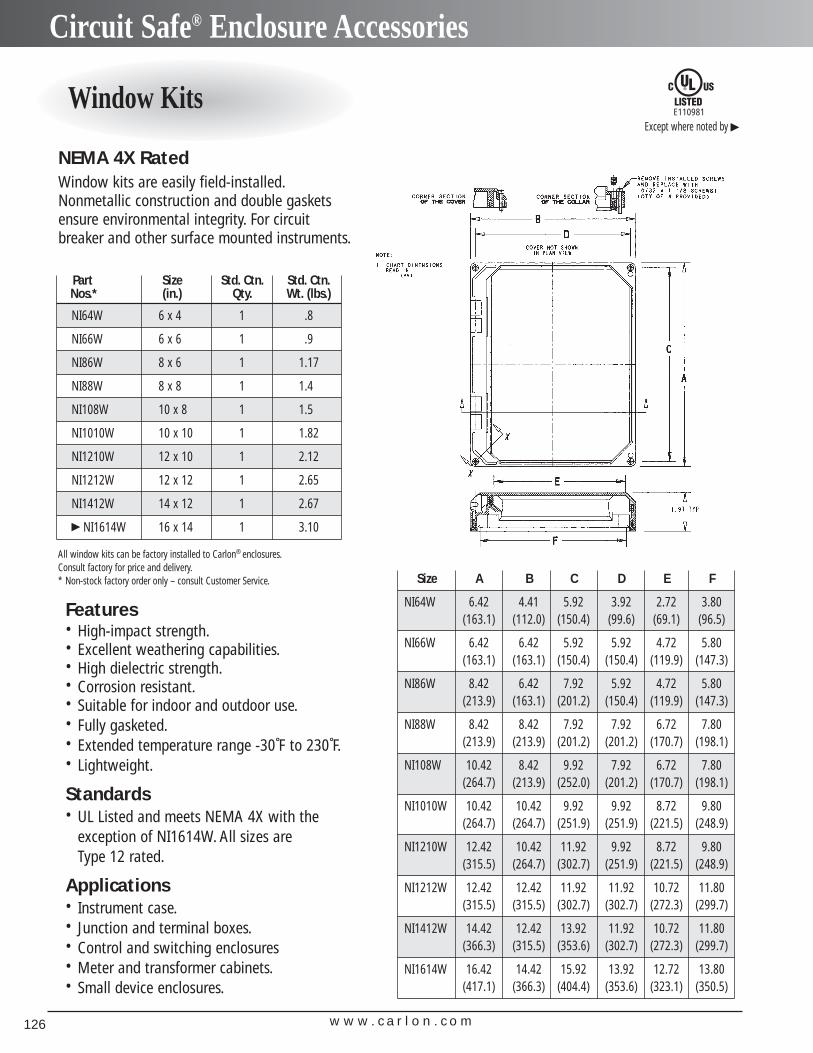
w w w . c a r l o n . c o m126
Circuit Safe® Enclosure Accessories
Window Kits
NEMA 4X RatedWindow kits are easily field-installed.Nonmetallic construction and double gaskets ensure environmental integrity. For circuitbreaker and other surface mounted instruments.
E110981
Except where noted by �
Features• High-impact strength.• Excellent weathering capabilities.• High dielectric strength.• Corrosion resistant.• Suitable for indoor and outdoor use.• Fully gasketed.• Extended temperature range -30˚F to 230˚F.• Lightweight.
Standards• UL Listed and meets NEMA 4X with the
exception of NI1614W. All sizes are Type 12 rated.
Applications• Instrument case.• Junction and terminal boxes.• Control and switching enclosures• Meter and transformer cabinets.• Small device enclosures.
Part Size Std. Ctn. Std. Ctn.Nos.* (in.) Qty. Wt. (lbs.)
NI64W 6 x 4 1 .8
NI66W 6 x 6 1 .9
NI86W 8 x 6 1 1.17
NI88W 8 x 8 1 1.4
NI108W 10 x 8 1 1.5
NI1010W 10 x 10 1 1.82
NI1210W 12 x 10 1 2.12
NI1212W 12 x 12 1 2.65
NI1412W 14 x 12 1 2.67
� NI1614W 16 x 14 1 3.10
All window kits can be factory installed to Carlon® enclosures.Consult factory for price and delivery.* Non-stock factory order only – consult Customer Service. Size A B C D E F
NI64W 6.42 4.41 5.92 3.92 2.72 3.80(163.1) (112.0) (150.4) (99.6) (69.1) (96.5)
NI66W 6.42 6.42 5.92 5.92 4.72 5.80(163.1) (163.1) (150.4) (150.4) (119.9) (147.3)
NI86W 8.42 6.42 7.92 5.92 4.72 5.80(213.9) (163.1) (201.2) (150.4) (119.9) (147.3)
NI88W 8.42 8.42 7.92 7.92 6.72 7.80(213.9) (213.9) (201.2) (201.2) (170.7) (198.1)
NI108W 10.42 8.42 9.92 7.92 6.72 7.80(264.7) (213.9) (252.0) (201.2) (170.7) (198.1)
NI1010W 10.42 10.42 9.92 9.92 8.72 9.80(264.7) (264.7) (251.9) (251.9) (221.5) (248.9)
NI1210W 12.42 10.42 11.92 9.92 8.72 9.80(315.5) (264.7) (302.7) (251.9) (221.5) (248.9)
NI1212W 12.42 12.42 11.92 11.92 10.72 11.80(315.5) (315.5) (302.7) (302.7) (272.3) (299.7)
NI1412W 14.42 12.42 13.92 11.92 10.72 11.80(366.3) (315.5) (353.6) (302.7) (272.3) (299.7)
NI1614W 16.42 14.42 15.92 13.92 12.72 13.80(417.1) (366.3) (404.4) (353.6) (323.1) (350.5)
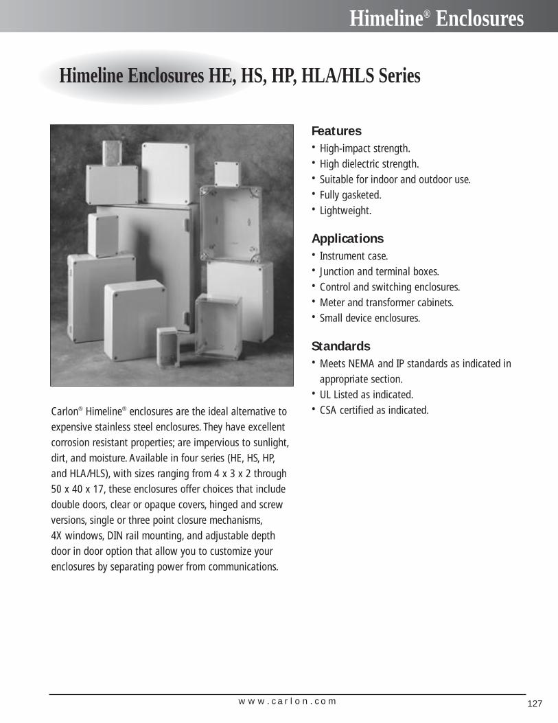
w w w . c a r l o n . c o m 127
Himeline® Enclosures
Himeline Enclosures HE, HS, HP, HLA/HLS Series
Carlon® Himeline® enclosures are the ideal alternative to expensive stainless steel enclosures. They have excellent corrosion resistant properties; are impervious to sunlight,dirt, and moisture. Available in four series (HE, HS, HP,and HLA/HLS), with sizes ranging from 4 x 3 x 2 through 50 x 40 x 17, these enclosures offer choices that includedouble doors, clear or opaque covers, hinged and screwversions, single or three point closure mechanisms,4X windows, DIN rail mounting, and adjustable depthdoor in door option that allow you to customize yourenclosures by separating power from communications.
Features• High-impact strength.• High dielectric strength.• Suitable for indoor and outdoor use.• Fully gasketed.• Lightweight.
Applications• Instrument case.• Junction and terminal boxes.• Control and switching enclosures.• Meter and transformer cabinets.• Small device enclosures.
Standards• Meets NEMA and IP standards as indicated in
appropriate section.• UL Listed as indicated.• CSA certified as indicated.
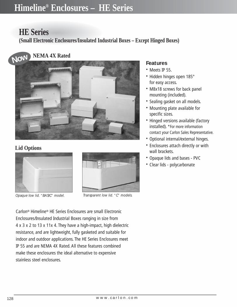
w w w . c a r l o n . c o m128
Himeline® Enclosures – HE Series
HE Series (Small Electronic Enclosures/Insulated Industrial Boxes – Except Hinged Boxes)
Lid Options
Features• Meets IP 55.• Hidden hinges open 185°
for easy access.• M8x18 screws for back panel
mounting (included).• Sealing gasket on all models.• Mounting plate available for
specific sizes.• Hinged versions available (factory
installed). *For more information contact your Carlon Sales Representative.
• Optional internal/external hinges.• Enclosures attach directly or with
wall brackets.• Opaque lids and bases - PVC• Clear lids - polycarbonate
Opaque low lid. “BASIC” model. Transparent low lid. “C” models.
NEMA 4X RatedNow
Carlon® Himeline® HE Series Enclosures are small Electronic
Enclosures/Insulated Industrial Boxes ranging in size from
4 x 3 x 2 to 13 x 11x 4. They have a high-impact, high dielectric
resistance, and are lightweight, fully gasketed and suitable for
indoor and outdoor applications. The HE Series Enclosures meet
IP 55 and are NEMA 4X Rated. All these features combined
make these enclosures the ideal alternative to expensive
stainless steel enclosures.
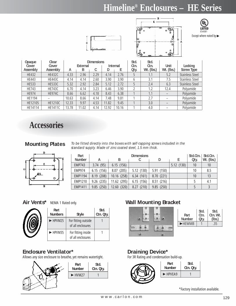
w w w . c a r l o n . c o m 129
Himeline® Enclosures – HE Series
E54381
Except where noted by �
Opaque Clear Dimensions Std. Std.Cover Cover External Internal Ctn. Ctn. Unit Locking
Assembly Assembly A B C D E Qty. Wt. (lbs.) Wt. (lbs.) Screw TypeHE432 HE432C 4.33 2.96 2.29 4.14 2.76 5 1.1 5.2 Stainless SteelHE443 HE443C 4.14 4.14 2.60 3.90 3.90 6 3.1 7.5 Stainless SteelHE533 HE533C 5.32 2.92 2.84 5.12 2.72 5 2.4 6.3 Stainless SteelHE743 HE743C 6.70 4.14 3.23 6.46 3.90 2 1.2 12.4 PolyamideHE974 HE974C 8.66 6.62 4.18 8.43 6.38 1 1.1 – PolyamideHE1194 – 10.63 8.66 4.14 7.48 9.81 1 2.7 – PolyamideHE12105 HE1210C 12.33 9.97 4.53 11.82 9.45 1 3.0 – PolyamideHE14114 HE1411C 13.78 11.02 4.14 12.92 10.16 1 4.0 – Polyamide
Wall Mounting Bracket
Mounting Plates To be fitted directly into the boxes with self-tapping screws included in the standard supply. Made of zinc coated steel, 1.5 mm thick.
Std. Std.Part Ctn. Ctn. Wt.
Number Qty. (lbs.)�HEWMB 1 .35
Part Dimensions Std.Ctn. Std.Ctn.Number A B C D E Qty. Wt. (lbs.)EMP743 3.74 (95) 6.15 (156) 5.12 (130) 10 10EMP974 6.15 (156) 8.07 (205) 5.12 (130) 5.91 (150) 10 8.5EMP1194 8.19 (208) 10.16 (258) 6.34 (161) 8.70 (221) 10 13EMP1210 9.26 (235) 11.62 (295) 6.15 (156) 8.51 (216) 5 4.1EMP1411 9.85 (250) 12.60 (320) 8.27 (210) 9.85 (250) 5 3
Draining Device* For 3R Rating and condensation build-up.
Air Vents* NEMA 1 Rated only.
Enclosure Ventilator* Allows any size enclosure to breathe, yet remains watertight.
*Factory installation available.
Part Std.Number Ctn. Qty.
� HVM27 1
Part Std.Number Ctn. Qty.
� HPVEA9 1
Part Std.Numbers Style Ctn. Qty.
� HPVM25 For fitting outside 1of all enclosures
� HPVM35 For fitting inside 1of all enclosures
Accessories
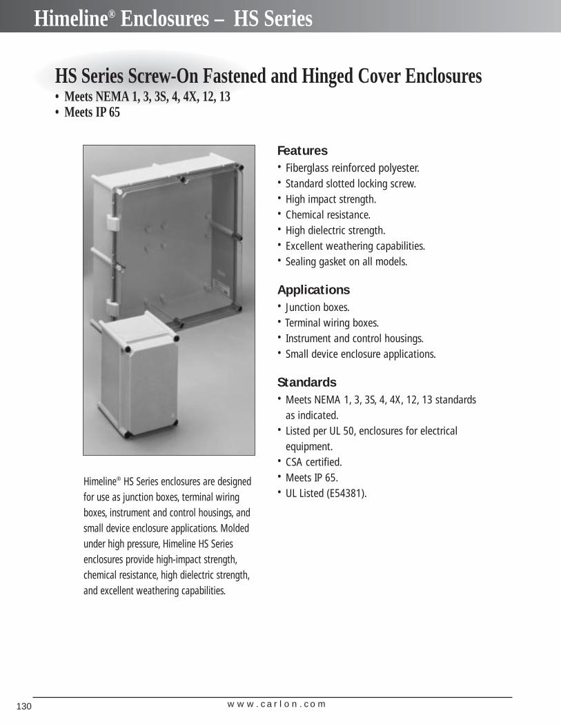
w w w . c a r l o n . c o m130
Himeline® Enclosures – HS Series
HS Series Screw-On Fastened and Hinged Cover Enclosures• Meets NEMA 1, 3, 3S, 4, 4X, 12, 13• Meets IP 65
Himeline® HS Series enclosures are designedfor use as junction boxes, terminal wiringboxes, instrument and control housings, andsmall device enclosure applications. Moldedunder high pressure, Himeline HS Seriesenclosures provide high-impact strength,chemical resistance, high dielectric strength,and excellent weathering capabilities.
Features• Fiberglass reinforced polyester.• Standard slotted locking screw.• High impact strength.• Chemical resistance.• High dielectric strength.• Excellent weathering capabilities.• Sealing gasket on all models.
Applications• Junction boxes.• Terminal wiring boxes.• Instrument and control housings.• Small device enclosure applications.
Standards• Meets NEMA 1, 3, 3S, 4, 4X, 12, 13 standards
as indicated.• Listed per UL 50, enclosures for electrical
equipment.• CSA certified.• Meets IP 65.• UL Listed (E54381).
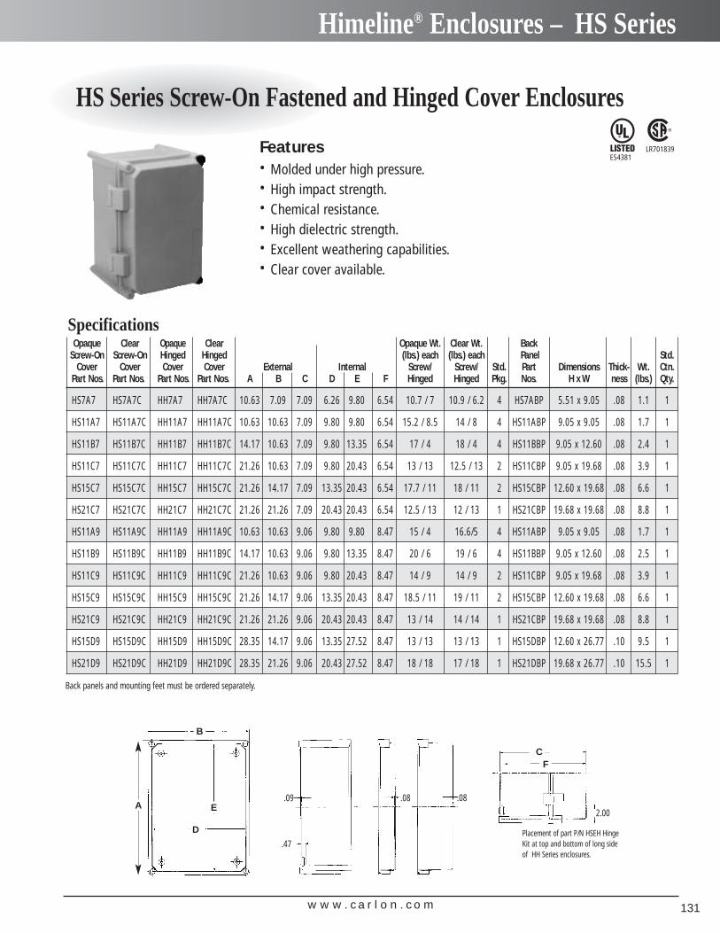
w w w . c a r l o n . c o m 131
Himeline® Enclosures – HS Series
HS Series Screw-On Fastened and Hinged Cover Enclosures
Opaque Clear Opaque Clear Opaque Wt. Clear Wt. BackScrew-On Screw-On Hinged Hinged (lbs.) each (lbs.) each Panel Std.
Cover Cover Cover Cover External Internal Screw/ Screw/ Std. Part Dimensions Thick- Wt. Ctn.Part Nos. Part Nos. Part Nos. Part Nos. A B C D E F Hinged Hinged Pkg. Nos. H x W ness (lbs.) Qty.
HS7A7 HS7A7C HH7A7 HH7A7C 10.63 7.09 7.09 6.26 9.80 6.54 10.7 / 7 10.9 / 6.2 4 HS7ABP 5.51 x 9.05 .08 1.1 1
HS11A7 HS11A7C HH11A7 HH11A7C 10.63 10.63 7.09 9.80 9.80 6.54 15.2 / 8.5 14 / 8 4 HS11ABP 9.05 x 9.05 .08 1.7 1
HS11B7 HS11B7C HH11B7 HH11B7C 14.17 10.63 7.09 9.80 13.35 6.54 17 / 4 18 / 4 4 HS11BBP 9.05 x 12.60 .08 2.4 1
HS11C7 HS11C7C HH11C7 HH11C7C 21.26 10.63 7.09 9.80 20.43 6.54 13 / 13 12.5 / 13 2 HS11CBP 9.05 x 19.68 .08 3.9 1
HS15C7 HS15C7C HH15C7 HH15C7C 21.26 14.17 7.09 13.35 20.43 6.54 17.7 / 11 18 / 11 2 HS15CBP 12.60 x 19.68 .08 6.6 1
HS21C7 HS21C7C HH21C7 HH21C7C 21.26 21.26 7.09 20.43 20.43 6.54 12.5 / 13 12 / 13 1 HS21CBP 19.68 x 19.68 .08 8.8 1
HS11A9 HS11A9C HH11A9 HH11A9C 10.63 10.63 9.06 9.80 9.80 8.47 15 / 4 16.6/5 4 HS11ABP 9.05 x 9.05 .08 1.7 1
HS11B9 HS11B9C HH11B9 HH11B9C 14.17 10.63 9.06 9.80 13.35 8.47 20 / 6 19 / 6 4 HS11BBP 9.05 x 12.60 .08 2.5 1
HS11C9 HS11C9C HH11C9 HH11C9C 21.26 10.63 9.06 9.80 20.43 8.47 14 / 9 14 / 9 2 HS11CBP 9.05 x 19.68 .08 3.9 1
HS15C9 HS15C9C HH15C9 HH15C9C 21.26 14.17 9.06 13.35 20.43 8.47 18.5 / 11 19 / 11 2 HS15CBP 12.60 x 19.68 .08 6.6 1
HS21C9 HS21C9C HH21C9 HH21C9C 21.26 21.26 9.06 20.43 20.43 8.47 13 / 14 14 / 14 1 HS21CBP 19.68 x 19.68 .08 8.8 1
HS15D9 HS15D9C HH15D9 HH15D9C 28.35 14.17 9.06 13.35 27.52 8.47 13 / 13 13 / 13 1 HS15DBP 12.60 x 26.77 .10 9.5 1
HS21D9 HS21D9C HH21D9 HH21D9C 28.35 21.26 9.06 20.43 27.52 8.47 18 / 18 17 / 18 1 HS21DBP 19.68 x 26.77 .10 15.5 1
Specifications
Features• Molded under high pressure.• High impact strength.• Chemical resistance.• High dielectric strength.• Excellent weathering capabilities.• Clear cover available.
B
D
E
CF
Placement of part P/N HSEH HingeKit at top and bottom of long sideof HH Series enclosures.
2.00
.08.08.09
.47
A
LR701839E54381
Back panels and mounting feet must be ordered separately.
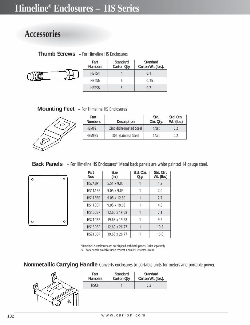
w w w . c a r l o n . c o m132
Himeline® Enclosures – HS Series
Accessories
Thumb Screws – For Himeline HS Enclosures
Part Standard Standard Numbers Carton Qty. Carton Wt. (lbs.).
HSTS4 4 0.1
HSTS6 6 0.15
HSTS8 8 0.2
Nonmetallic Carrying Handle Converts enclosures to portable units for meters and portable power.
Part Standard Standard Numbers Carton Qty. Carton Wt. (lbs.).
HSCH 1 0.2
Mounting Feet – For Himeline HS Enclosures
Part Std. Std. Ctn.Numbers Description Ctn. Qty. Wt. (lbs.)
HSMFZ Zinc dichromated Steel 4/set 0.2
HSMFSS 304 Stainless Steel 4/set 0.2
Back Panels – For Himeline HS Enclosures* Metal back panels are white painted 14 gauge steel.
Part Size Std. Ctn. Std. Ctn.Nos. (in.) Qty. Wt. (lbs.)
HS7ABP 5.51 x 9.05 1 1.2
HS11ABP 9.05 x 9.05 1 2.0
HS11BBP 9.05 x 12.60 1 2.7
HS11CBP 9.05 x 19.68 1 4.3
HS15CBP 12.60 x 19.68 1 7.1
HS21CBP 19.68 x 19.68 1 9.6
HS15DBP 12.60 x 26.77 1 10.2
HS21DBP 19.68 x 26.77 1 16.6
*Himeline HS enclosures are not shipped with back panels. Order separately.PVC back panels available upon request. Consult Customer Service.
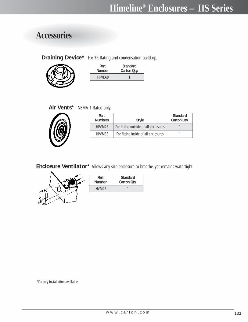
w w w . c a r l o n . c o m 133
Himeline® Enclosures – HS Series
Accessories
Draining Device* For 3R Rating and condensation build-up.
Air Vents* NEMA 1 Rated only.
Enclosure Ventilator* Allows any size enclosure to breathe, yet remains watertight.
Part Standard Number Carton Qty.
HPVEA9 1
Part Standard Number Carton Qty.
HVM27 1
Part Standard Numbers Style Carton Qty.
HPVM25 For fitting outside of all enclosures 1
HPVM35 For fitting inside of all enclosures 1
*Factory installation available.
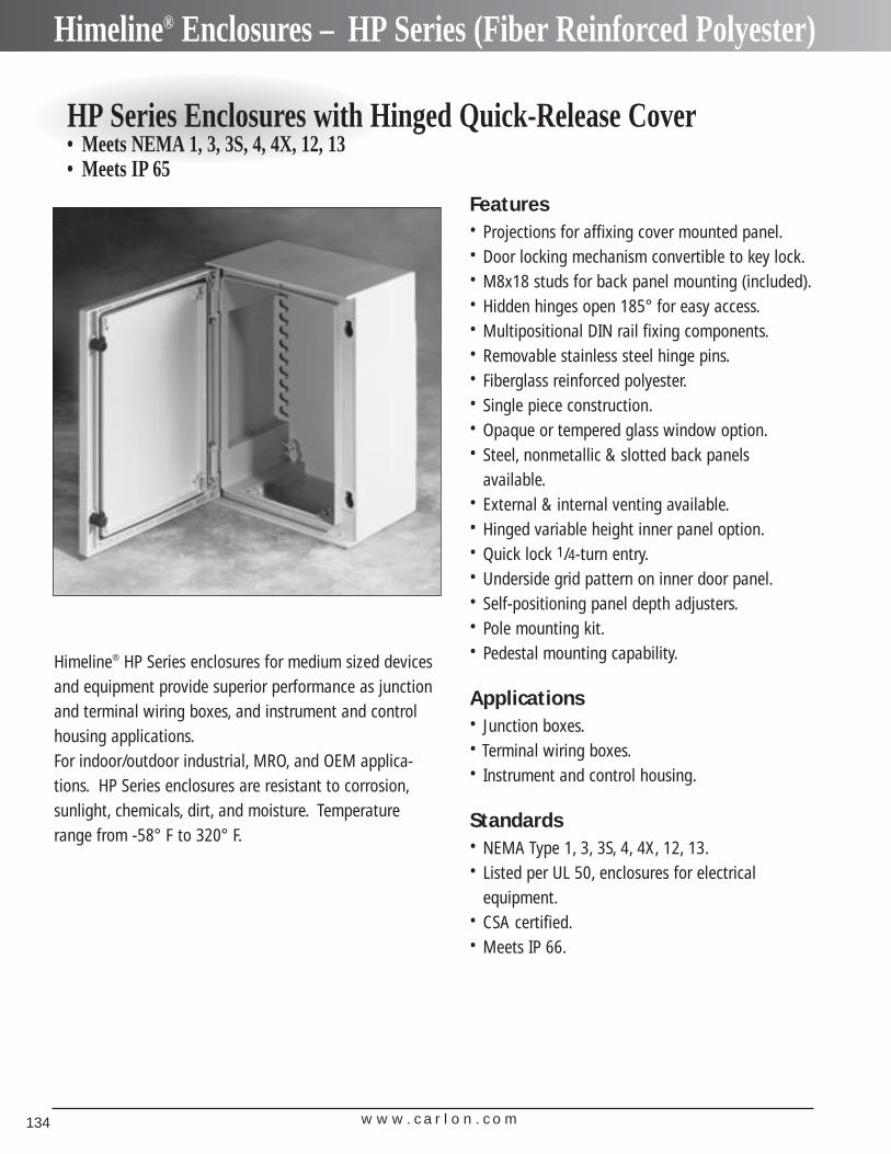
w w w . c a r l o n . c o m134
Himeline® Enclosures – HP Series (Fiber Reinforced Polyester)
HP Series Enclosures with Hinged Quick-Release Cover• Meets NEMA 1, 3, 3S, 4, 4X, 12, 13• Meets IP 65
Himeline® HP Series enclosures for medium sized devicesand equipment provide superior performance as junctionand terminal wiring boxes, and instrument and controlhousing applications.For indoor/outdoor industrial, MRO, and OEM applica-tions. HP Series enclosures are resistant to corrosion,sunlight, chemicals, dirt, and moisture. Temperaturerange from -58° F to 320° F.
Features• Projections for affixing cover mounted panel.• Door locking mechanism convertible to key lock.• M8x18 studs for back panel mounting (included).• Hidden hinges open 185° for easy access.• Multipositional DIN rail fixing components.• Removable stainless steel hinge pins.• Fiberglass reinforced polyester.• Single piece construction.• Opaque or tempered glass window option.• Steel, nonmetallic & slotted back panels
available.• External & internal venting available.• Hinged variable height inner panel option.• Quick lock 1/4-turn entry.• Underside grid pattern on inner door panel.• Self-positioning panel depth adjusters.• Pole mounting kit.• Pedestal mounting capability.
Applications• Junction boxes.• Terminal wiring boxes.• Instrument and control housing.
Standards• NEMA Type 1, 3, 3S, 4, 4X, 12, 13.• Listed per UL 50, enclosures for electrical
equipment.• CSA certified.• Meets IP 66.
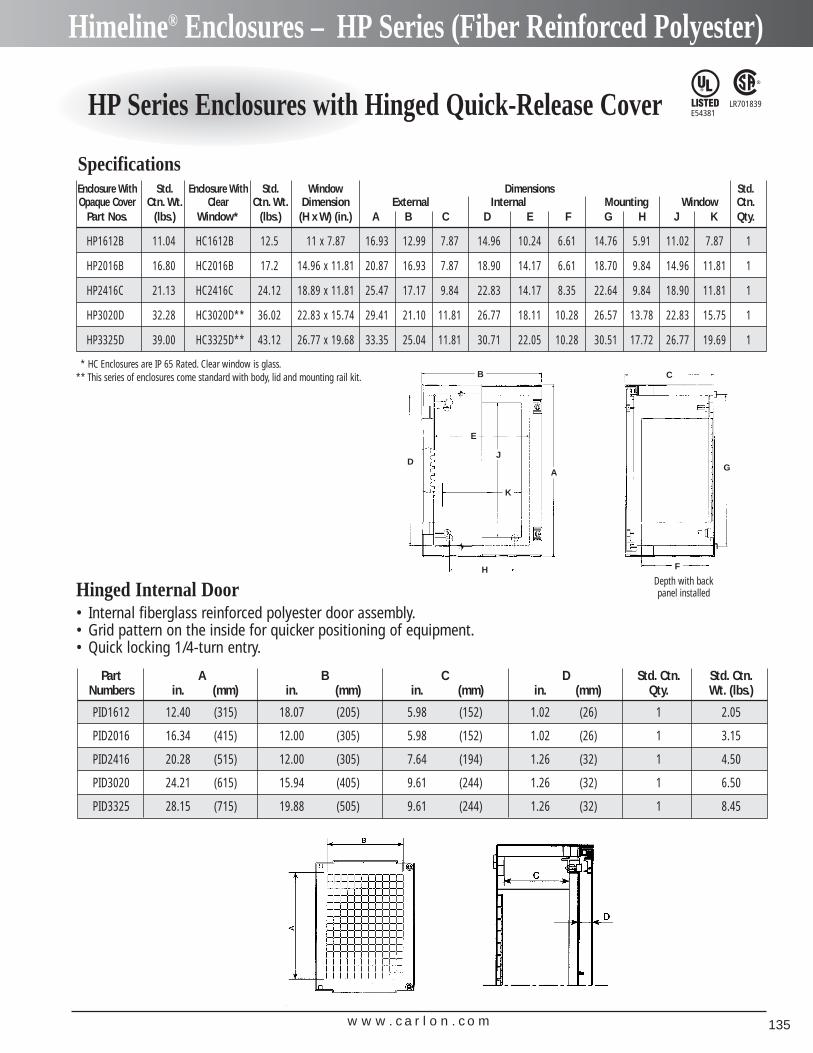
w w w . c a r l o n . c o m 135
Himeline® Enclosures – HP Series (Fiber Reinforced Polyester)
HP Series Enclosures with Hinged Quick-Release Cover LR701839E54381
Enclosure With Std. Enclosure With Std. Window Dimensions Std.Opaque Cover Ctn. Wt. Clear Ctn. Wt. Dimension External Internal Mounting Window Ctn.
Part Nos. (lbs.) Window* (lbs.) (H x W) (in.) A B C D E F G H J K Qty.
HP1612B 11.04 HC1612B 12.5 11 x 7.87 16.93 12.99 7.87 14.96 10.24 6.61 14.76 5.91 11.02 7.87 1
HP2016B 16.80 HC2016B 17.2 14.96 x 11.81 20.87 16.93 7.87 18.90 14.17 6.61 18.70 9.84 14.96 11.81 1
HP2416C 21.13 HC2416C 24.12 18.89 x 11.81 25.47 17.17 9.84 22.83 14.17 8.35 22.64 9.84 18.90 11.81 1
HP3020D 32.28 HC3020D** 36.02 22.83 x 15.74 29.41 21.10 11.81 26.77 18.11 10.28 26.57 13.78 22.83 15.75 1
HP3325D 39.00 HC3325D** 43.12 26.77 x 19.68 33.35 25.04 11.81 30.71 22.05 10.28 30.51 17.72 26.77 19.69 1
Specifications
* HC Enclosures are IP 65 Rated. Clear window is glass.** This series of enclosures come standard with body, lid and mounting rail kit.
• Internal fiberglass reinforced polyester door assembly.• Grid pattern on the inside for quicker positioning of equipment.• Quick locking 1/4-turn entry.
Hinged Internal Door
C
G
F
A
H
B
E
J
K
D
Depth with back panel installed
Part A B C D Std. Ctn. Std. Ctn.Numbers in. (mm) in. (mm) in. (mm) in. (mm) Qty. Wt. (lbs.)
PID1612 12.40 (315) 18.07 (205) 5.98 (152) 1.02 (26) 1 2.05
PID2016 16.34 (415) 12.00 (305) 5.98 (152) 1.02 (26) 1 3.15
PID2416 20.28 (515) 12.00 (305) 7.64 (194) 1.26 (32) 1 4.50
PID3020 24.21 (615) 15.94 (405) 9.61 (244) 1.26 (32) 1 6.50
PID3325 28.15 (715) 19.88 (505) 9.61 (244) 1.26 (32) 1 8.45
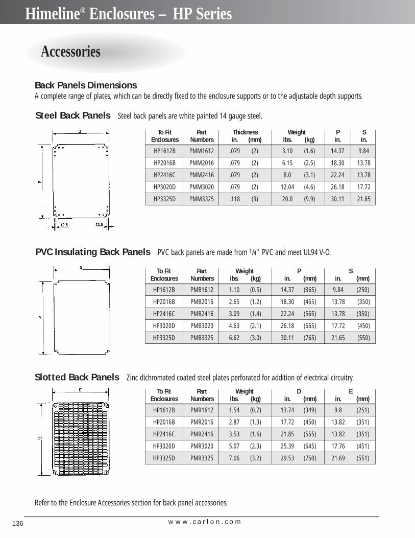
w w w . c a r l o n . c o m136
Himeline® Enclosures – HP Series
Accessories
Steel Back Panels Steel back panels are white painted 14 gauge steel.
To Fit Part Thickness Weight P SEnclosures Numbers in. (mm) lbs. (kg) in. in.
HP1612B PMM1612 .079 (2) 3.10 (1.6) 14.37 9.84
HP2016B PMM2016 .079 (2) 6.15 (2.5) 18.30 13.78
HP2416C PMM2416 .079 (2) 8.0 (3.1) 22.24 13.78
HP3020D PMM3020 .079 (2) 12.04 (4.6) 26.18 17.72
HP3325D PMM3325 .118 (3) 20.0 (9.9) 30.11 21.65
To Fit Part Weight P SEnclosures Numbers lbs. (kg) in. (mm) in. (mm)
HP1612B PMB1612 1.10 (0.5) 14.37 (365) 9.84 (250)
HP2016B PMB2016 2.65 (1.2) 18.30 (465) 13.78 (350)
HP2416C PMB2416 3.09 (1.4) 22.24 (565) 13.78 (350)
HP3020D PMB3020 4.63 (2.1) 26.18 (665) 17.72 (450)
HP3325D PMB3325 6.62 (3.0) 30.11 (765) 21.65 (550)
To Fit Part Weight D EEnclosures Numbers lbs. (kg) in. (mm) in. (mm)
HP1612B PMR1612 1.54 (0.7) 13.74 (349) 9.8 (251)
HP2016B PMR2016 2.87 (1.3) 17.72 (450) 13.82 (351)
HP2416C PMR2416 3.53 (1.6) 21.85 (555) 13.82 (351)
HP3020D PMR3020 5.07 (2.3) 25.39 (645) 17.76 (451)
HP3325D PMR3325 7.06 (3.2) 29.53 (750) 21.69 (551)
PVC Insulating Back Panels PVC back panels are made from 1/4" PVC and meet UL94 V-O.
Slotted Back Panels Zinc dichromated coated steel plates perforated for addition of electrical circuitry.
Refer to the Enclosure Accessories section for back panel accessories.
Back Panels DimensionsA complete range of plates, which can be directly fixed to the enclosure supports or to the adjustable depth supports.
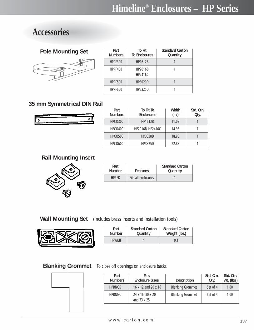
w w w . c a r l o n . c o m 137
Himeline® Enclosures – HP Series
Accessories
Blanking Grommet To close off openings on enclosure backs.
35 mm Symmetrical DIN Rail
Rail Mounting Insert
Wall Mounting Set (includes brass inserts and installation tools)
Pole Mounting Set Part To Fit Standard CartonNumbers To Enclosures Quantity
HPPF300 HP1612B 1
HPPF400 HP2016B 1HP2416C
HPPF500 HP3020D 1
HPPF600 HP3325D 1
Part Standard CartonNumber Features Quantity
HPRFK Fits all enclosures 1
Part Standard Carton Standard CartonNumber Quantity Weight (lbs.)
HPWMF 4 0.1
Part To Fit To Width Std. Ctn.Numbers Enclosures (in.) Qty.
HPCO300 HP1612B 11.02 1
HPCO400 HP2016B, HP2416C 14.96 1
HPCO500 HP3020D 18.90 1
HPCO600 HP3325D 22.83 1
Part Fits Std. Ctn. Std. Ctn.Numbers Enclosure Sizes Description Qty. Wt. (lbs.)
HPBNGB 16 x 12 and 20 x 16 Blanking Grommet Set of 4 1.00
HPBNGC 24 x 16, 30 x 20 Blanking Grommet Set of 4 1.00and 33 x 25
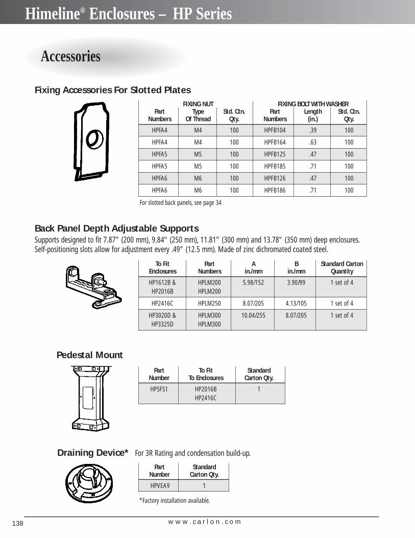
w w w . c a r l o n . c o m138
Himeline® Enclosures – HP Series
Accessories
Draining Device* For 3R Rating and condensation build-up.
Part Standard Number Carton Qty.
HPVEA9 1
Part To Fit StandardNumber To Enclosures Carton Qty.
HPSFS1 HP2016B 1HP2416C
To Fit Part A B Standard CartonEnclosures Numbers in./mm in./mm Quantity
HP1612B & HPLM200 5.98/152 3.90/99 1 set of 4HP2016B HPLM200
HP2416C HPLM250 8.07/205 4.13/105 1 set of 4
HP3020D & HPLM300 10.04/255 8.07/205 1 set of 4HP3325D HPLM300
FIXING NUT FIXING BOLT WITH WASHERPart Type Std. Ctn. Part Length Std. Ctn.
Numbers Of Thread Qty. Numbers (in.) Qty.
HPFA4 M4 100 HPFB104 .39 100
HPFA4 M4 100 HPFB164 .63 100
HPFA5 M5 100 HPFB125 .47 100
HPFA5 M5 100 HPFB185 .71 100
HPFA6 M6 100 HPFB126 .47 100
HPFA6 M6 100 HPFB186 .71 100
*Factory installation available.
Fixing Accessories For Slotted Plates
For slotted back panels, see page 34
Back Panel Depth Adjustable SupportsSupports designed to fit 7.87" (200 mm), 9.84" (250 mm), 11.81" (300 mm) and 13.78" (350 mm) deep enclosures.Self-positioning slots allow for adjustment every .49" (12.5 mm). Made of zinc dichromated coated steel.
Pedestal Mount
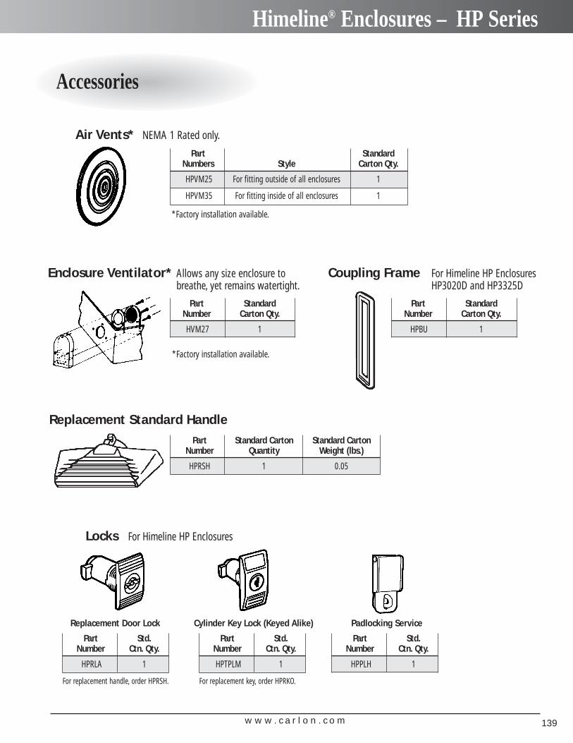
w w w . c a r l o n . c o m 139
Himeline® Enclosures – HP Series
Accessories
Air Vents* NEMA 1 Rated only.
Enclosure Ventilator* Allows any size enclosure tobreathe, yet remains watertight.
Part Standard Number Carton Qty.
HVM27 1
Part Standard Numbers Style Carton Qty.
HPVM25 For fitting outside of all enclosures 1
HPVM35 For fitting inside of all enclosures 1
Locks For Himeline HP Enclosures
Replacement Door Lock Cylinder Key Lock (Keyed Alike) Padlocking Service
Replacement Standard Handle
Part Standard Number Carton Qty.
HPBU 1
Coupling Frame For Himeline HP EnclosuresHP3020D and HP3325D
Part Std.Number Ctn. Qty.
HPRLA 1
For replacement handle, order HPRSH.
Part Std.Number Ctn. Qty.
HPTPLM 1
For replacement key, order HPRKO.
Part Std.Number Ctn. Qty.
HPPLH 1
Part Standard Carton Standard CartonNumber Quantity Weight (lbs.)
HPRSH 1 0.05
*Factory installation available.
*Factory installation available.
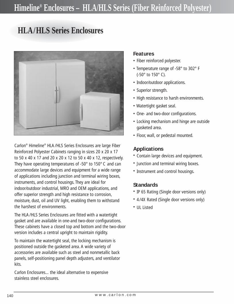
w w w . c a r l o n . c o m140
Himeline® Enclosures – HLA/HLS Series (Fiber Reinforced Polyester)
HLA/HLS Series Enclosures
Carlon® Himeline® HLA/HLS Series Enclosures are large FiberReinforced Polyester Cabinets ranging in sizes 20 x 20 x 17 to 50 x 40 x 17 and 20 x 20 x 12 to 50 x 40 x 12, respectively.They have operating temperatures of -50° to 150° C and canaccommodate large devices and equipment for a wide range of applications including junction and terminal wiring boxes,instruments, and control housings. They are ideal forindoor/outdoor industrial, MRO and OEM applications, andoffer superior strength and high resistance to corrosion,moisture, dust, oil and UV light, enabling them to withstand the harshest of environments.
The HLA/HLS Series Enclosures are fitted with a watertight gasket and are available in one-and two-door configurations.These cabinets have a closed top and bottom and the two-door version includes a central upright to maintain rigidity.
To maintain the watertight seal, the locking mechanism is positioned outside the gasketed area. A wide variety of accessories are available such as steel and nonmetallic backpanels, self-positioning panel depth adjusters, and ventilatorkits.
Carlon Enclosures…the ideal alternative to expensive stainless steel enclosures.
Features• Fiber reinforced polyester.
• Temperature range of -58° to 302° F (-50° to 150° C).
• Indoor/outdoor applications.
• Superior strength.
• High resistance to harsh environments.
• Watertight gasket seal.
• One- and two-door configurations.
• Locking mechanism and hinge are outsidegasketed area.
• Floor, wall, or pedestal mounted.
Applications• Contain large devices and equipment.
• Junction and terminal wiring boxes.
• Instrument and control housings.
Standards• IP 65 Rating (Single door versions only)
• 4/4X Rated (Single door versions only)
• UL Listed
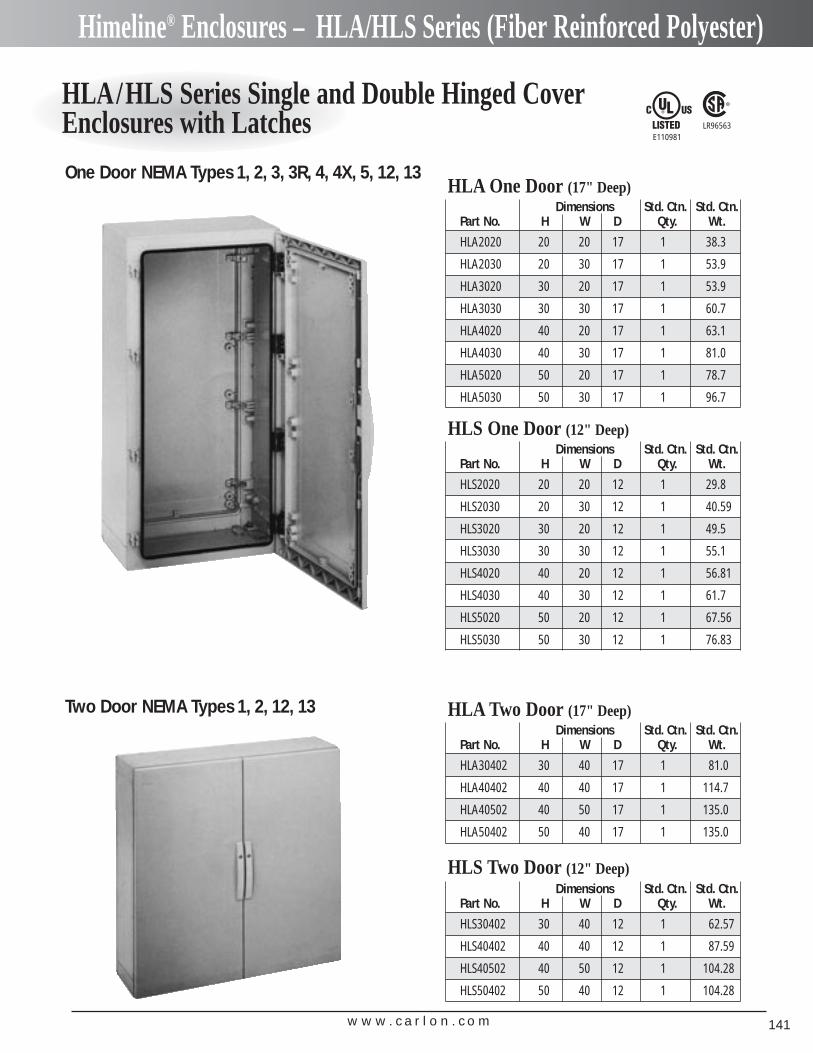
w w w . c a r l o n . c o m 141
Himeline® Enclosures – HLA/HLS Series (Fiber Reinforced Polyester)
HLA/HLS Series Single and Double Hinged CoverEnclosures with Latches LR96563
E110981
One Door NEMA Types 1, 2, 3, 3R, 4, 4X, 5, 12, 13
Two Door NEMA Types 1, 2, 12, 13
Dimensions Std. Ctn. Std. Ctn.Part No. H W D Qty. Wt.
HLA2020 20 20 17 1 38.3
HLA2030 20 30 17 1 53.9
HLA3020 30 20 17 1 53.9
HLA3030 30 30 17 1 60.7
HLA4020 40 20 17 1 63.1
HLA4030 40 30 17 1 81.0
HLA5020 50 20 17 1 78.7
HLA5030 50 30 17 1 96.7
HLA One Door (17" Deep)
Dimensions Std. Ctn. Std. Ctn.Part No. H W D Qty. Wt.
HLS2020 20 20 12 1 29.8
HLS2030 20 30 12 1 40.59
HLS3020 30 20 12 1 49.5
HLS3030 30 30 12 1 55.1
HLS4020 40 20 12 1 56.81
HLS4030 40 30 12 1 61.7
HLS5020 50 20 12 1 67.56
HLS5030 50 30 12 1 76.83
HLS One Door (12" Deep)
Dimensions Std. Ctn. Std. Ctn.Part No. H W D Qty. Wt.
HLA30402 30 40 17 1 81.0
HLA40402 40 40 17 1 114.7
HLA40502 40 50 17 1 135.0
HLA50402 50 40 17 1 135.0
HLA Two Door (17" Deep)
Dimensions Std. Ctn. Std. Ctn.Part No. H W D Qty. Wt.
HLS30402 30 40 12 1 62.57
HLS40402 40 40 12 1 87.59
HLS40502 40 50 12 1 104.28
HLS50402 50 40 12 1 104.28
HLS Two Door (12" Deep)
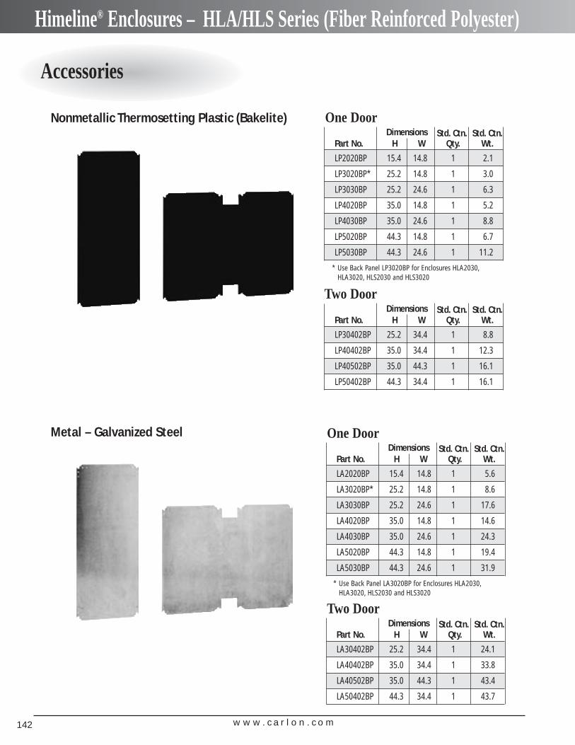
w w w . c a r l o n . c o m142
Himeline® Enclosures – HLA/HLS Series (Fiber Reinforced Polyester)
Accessories
Dimensions Std. Ctn. Std. Ctn.Part No. H W Qty. Wt.
LP2020BP 15.4 14.8 1 2.1
LP3020BP* 25.2 14.8 1 3.0
LP3030BP 25.2 24.6 1 6.3
LP4020BP 35.0 14.8 1 5.2
LP4030BP 35.0 24.6 1 8.8
LP5020BP 44.3 14.8 1 6.7
LP5030BP 44.3 24.6 1 11.2
Nonmetallic Thermosetting Plastic (Bakelite)
Metal – Galvanized Steel
One Door
Dimensions Std. Ctn. Std. Ctn.Part No. H W Qty. Wt.
LP30402BP 25.2 34.4 1 8.8
LP40402BP 35.0 34.4 1 12.3
LP40502BP 35.0 44.3 1 16.1
LP50402BP 44.3 34.4 1 16.1
Two Door
* Use Back Panel LP3020BP for Enclosures HLA2030,HLA3020, HLS2030 and HLS3020
Dimensions Std. Ctn. Std. Ctn.Part No. H W Qty. Wt.
LA2020BP 15.4 14.8 1 5.6
LA3020BP* 25.2 14.8 1 8.6
LA3030BP 25.2 24.6 1 17.6
LA4020BP 35.0 14.8 1 14.6
LA4030BP 35.0 24.6 1 24.3
LA5020BP 44.3 14.8 1 19.4
LA5030BP 44.3 24.6 1 31.9
One Door
Dimensions Std. Ctn. Std. Ctn.Part No. H W Qty. Wt.
LA30402BP 25.2 34.4 1 24.1
LA40402BP 35.0 34.4 1 33.8
LA40502BP 35.0 44.3 1 43.4
LA50402BP 44.3 34.4 1 43.7
Two Door
* Use Back Panel LA3020BP for Enclosures HLA2030,HLA3020, HLS2030 and HLS3020
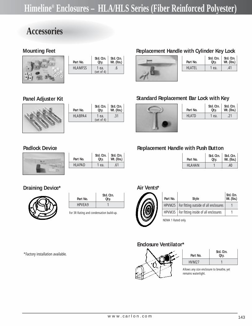
w w w . c a r l o n . c o m 143
Himeline® Enclosures – HLA/HLS Series (Fiber Reinforced Polyester)
Accessories
Std. Ctn. Std. Ctn.Part No. Qty. Wt. (lbs.)
HLAMFSS 1 ea. .6(set of 4)
Std. Ctn. Std. Ctn.Part No. Qty. Wt. (lbs.)
HLATEL 1 ea. .41
Std. Ctn. Std. Ctn.Part No. Qty. Wt. (lbs.)
HLABPA4 1 ea. .31(set of 4)
Mounting Feet Replacement Handle with Cylinder Key Lock
Std. Ctn. Std. Ctn.Part No. Qty. Wt. (lbs.)
HLATD 1 ea. .21
Standard Replacement Bar Lock with KeyPanel Adjuster Kit
Std. Ctn. Std. Ctn.Part No. Qty. Wt. (lbs.)
HLAPAD 1 ea. .61
Padlock Device
Std. Ctn.Part No. Qty.
HPVEA9 1
Draining Device*
Std. Ctn. Std. Ctn.Part No. Qty. Wt. (lbs.)
HLAHAN 1 .40
For 3R Rating and condensation build-up.
*Factory installation available.
Std. Ctn.Part No. Style Wt. (lbs.)
HPVM25 For fitting outside of all enclosures 1
HPVM35 For fitting inside of all enclosures 1
Std. Ctn.Part No. Qty.
HVM27 1
Enclosure Ventilator*
Allows any size enclosure to breathe, yetremains watertight.
Air Vents*
NEMA 1 Rated only.
Replacement Handle with Push Button
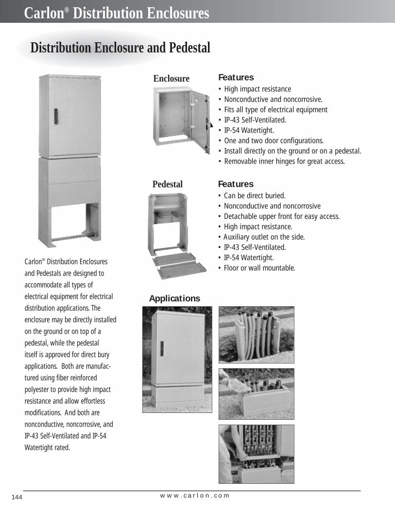
w w w . c a r l o n . c o m144
Carlon® Distribution Enclosures
Distribution Enclosure and Pedestal
Carlon® Distribution Enclosures
and Pedestals are designed to
accommodate all types of
electrical equipment for electrical
distribution applications. The
enclosure may be directly installed
on the ground or on top of a
pedestal, while the pedestal
itself is approved for direct bury
applications. Both are manufac-
tured using fiber reinforced
polyester to provide high impact
resistance and allow effortless
modifications. And both are
nonconductive, noncorrosive, and
IP-43 Self-Ventilated and IP-54
Watertight rated.
Features• High impact resistance• Nonconductive and noncorrosive.• Fits all type of electrical equipment• IP-43 Self-Ventilated.• IP-54 Watertight.• One and two door configurations.• Install directly on the ground or on a pedestal.• Removable inner hinges for great access.
Features• Can be direct buried.• Nonconductive and noncorrosive• Detachable upper front for easy access.• High impact resistance.• Auxiliary outlet on the side.• IP-43 Self-Ventilated.• IP-54 Watertight.• Floor or wall mountable.
Enclosure
Pedestal
Applications
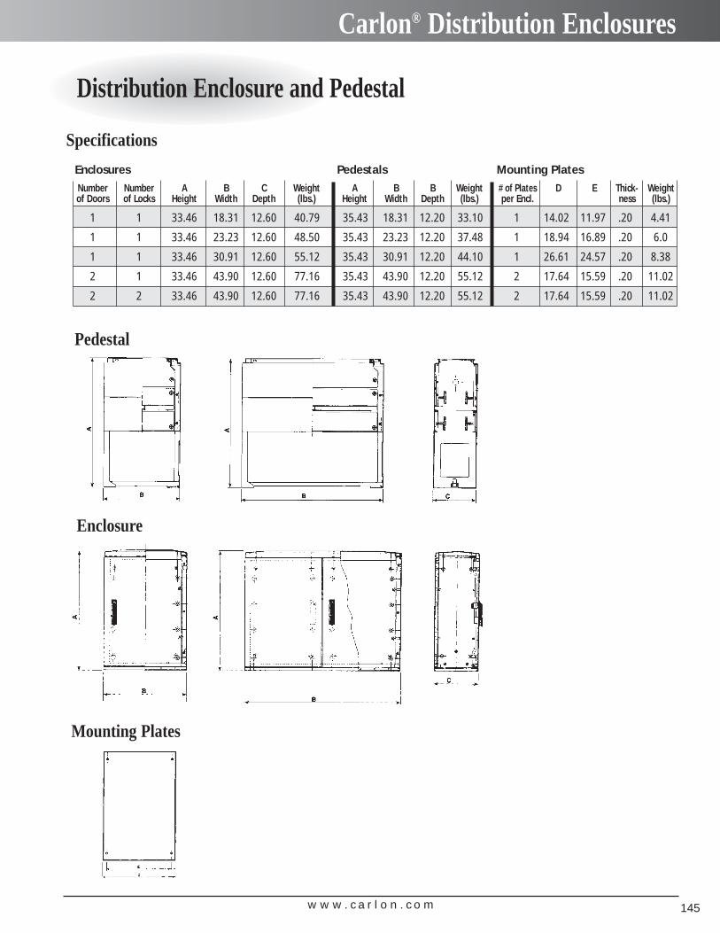
w w w . c a r l o n . c o m 145
Carlon® Distribution Enclosures
Distribution Enclosure and Pedestal
Number Number A B C Weight A B B Weight # of Plates D E Thick- Weightof Doors of Locks Height Width Depth (lbs.) Height Width Depth (lbs.) per Encl. ness (lbs.)
1 1 33.46 18.31 12.60 40.79 35.43 18.31 12.20 33.10 1 14.02 11.97 .20 4.41
1 1 33.46 23.23 12.60 48.50 35.43 23.23 12.20 37.48 1 18.94 16.89 .20 6.0
1 1 33.46 30.91 12.60 55.12 35.43 30.91 12.20 44.10 1 26.61 24.57 .20 8.38
2 1 33.46 43.90 12.60 77.16 35.43 43.90 12.20 55.12 2 17.64 15.59 .20 11.02
2 2 33.46 43.90 12.60 77.16 35.43 43.90 12.20 55.12 2 17.64 15.59 .20 11.02
Enclosures Pedestals Mounting Plates
Specifications
Pedestal
Enclosure
Mounting Plates
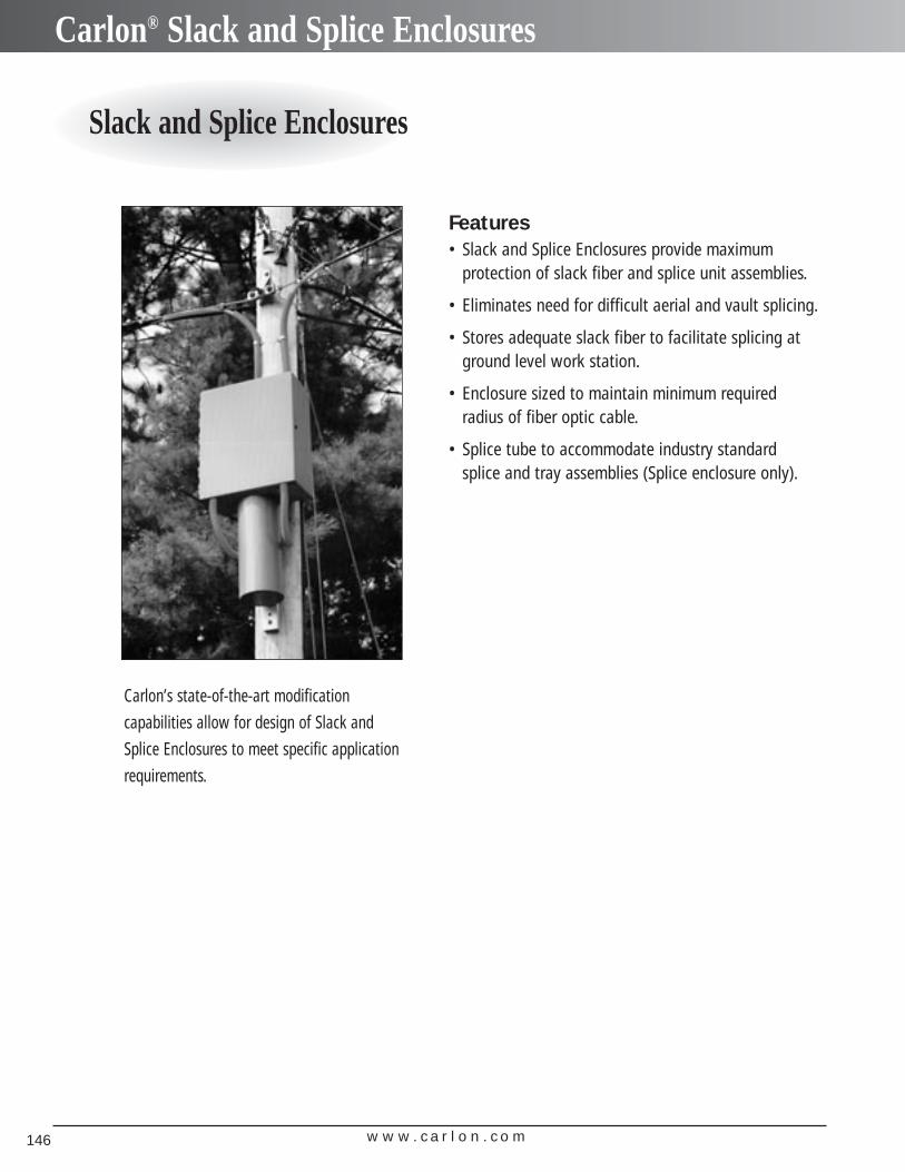
w w w . c a r l o n . c o m146
Carlon® Slack and Splice Enclosures
Slack and Splice Enclosures
Carlon’s state-of-the-art modification
capabilities allow for design of Slack and
Splice Enclosures to meet specific application
requirements.
Features• Slack and Splice Enclosures provide maximum
protection of slack fiber and splice unit assemblies.
• Eliminates need for difficult aerial and vault splicing.
• Stores adequate slack fiber to facilitate splicing atground level work station.
• Enclosure sized to maintain minimum requiredradius of fiber optic cable.
• Splice tube to accommodate industry standardsplice and tray assemblies (Splice enclosure only).
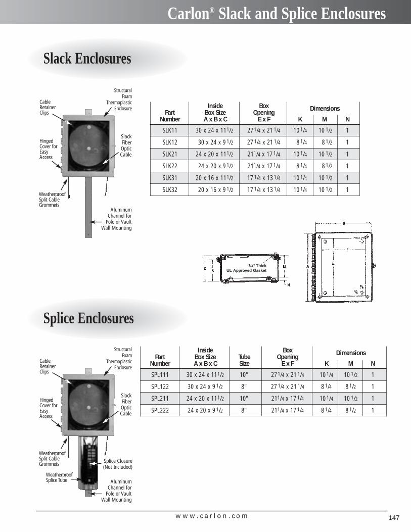
w w w . c a r l o n . c o m 147
Carlon® Slack and Splice Enclosures
Slack Enclosures
Splice Enclosures
Inside Box DimensionsPart Box Size Opening
Number A x B x C E x F K M N
SLK11 30 x 24 x 111/2 27 1/4 x 21 1/4 10 1/4 10 1/2 1
SLK12 30 x 24 x 9 1/2 27 1/4 x 21 1/4 8 1/4 8 1/2 1
SLK21 24 x 20 x 111/2 211/4 x 17 1/4 10 1/4 10 1/2 1
SLK22 24 x 20 x 9 1/2 211/4 x 17 1/4 8 1/4 8 1/2 1
SLK31 20 x 16 x 111/2 17 1/4 x 13 1/4 10 1/4 10 1/2 1
SLK32 20 x 16 x 9 1/2 17 1/4 x 13 1/4 10 1/4 10 1/2 1
Inside Box DimensionsPart Box Size Tube Opening
Number A x B x C Size E x F K M N
SPL111 30 x 24 x 111/2 10" 27 1/4 x 21 1/4 10 1/4 10 1/2 1
SPL122 30 x 24 x 9 1/2 8" 27 1/4 x 21 1/4 8 1/4 8 1/2 1
SPL211 24 x 20 x 111/2 10" 211/4 x 17 1/4 10 1/4 10 1/2 1
SPL222 24 x 20 x 9 1/2 8" 211/4 x 17 1/4 8 1/4 8 1/2 1
1/4" Thick UL Approved Gasket
Structural Foam
ThermoplasticEnclosure
SlackFiberOpticCable
WeatherproofSplit CableGrommets
HingedCover forEasy Access
Cable RetainerClips
WeatherproofSplice Tube
Splice Closure(Not Included)
AluminumChannel for
Pole or VaultWall Mounting
Structural Foam
ThermoplasticEnclosure
SlackFiberOpticCable
WeatherproofSplit CableGrommets
HingedCover forEasy Access
Cable RetainerClips
AluminumChannel for
Pole or VaultWall Mounting
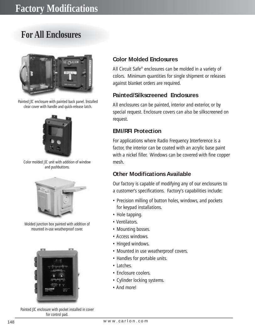
w w w . c a r l o n . c o m148
Factory Modifications
For All Enclosures
Color Molded Enclosures
All Circuit Safe® enclosures can be molded in a variety of colors. Minimum quantities for single shipment or releasesagainst blanket orders are required.
Painted/Silkscreened Enclosures
All enclosures can be painted, interior and exterior, or by special request. Enclosure covers can also be silkscreened onrequest.
EMI/RFI Protection
For applications where Radio Frequency Interference is a factor, the interior can be coated with an acrylic base paintwith a nickel filler. Windows can be covered with fine coppermesh.
Other Modifications Available
Our factory is capable of modifying any of our enclosures to a customer’s specifications. Factory’s capabilities include:
• Precision milling of button holes, windows, and pockets for keypad installations.
• Hole tapping.• Ventilators.• Mounting bosses.• Access windows.• Hinged windows.• Mounted in use weatherproof covers.• Handles for portable units.• Latches.• Enclosure coolers.• Cylinder locking systems.• And more!
Painted JIC enclosure with painted back panel. Installedclear cover with handle and quick-release latch.
Molded junction box painted with addition of mounted in-use weatherproof cover.
Painted JIC enclosure with pocket installed in cover for control pad.
Color molded JIC unit with addition of window and pushbuttons.
w w w . c a r l o n . c o m 149
General Information
NEMA Types – Definitions Pertaining to Nonhazardous Locations
Enclosures for Electrical EquipmentAn enclosure is a surrounding case constructed to provide protection from accidental contact with the enclosed equipment and to provide protection to the enclosed equipment from specified environmental conditions. A brief description of the more common types of enclosures used by the electrical industry follows.
Type 1 Enclosure: Intended for indoor use primarily to provide protection against contact with enclosedequipment and a degree of protection against falling dirt.
Type 2 Enclosure: Intended for indoor use primarily to provide a degree of protection against limitedamounts of falling water and dirt.
Type 3 Enclosure: Intended for outdoor use primarily to provide a degree of protection against wind-blown dust, rain, sleet and external ice formation.
Type 3R Enclosure: Intended for outdoor use primarily to provide a degree of protection against fallingrain, sleet and external ice formation.
Type 3S Enclosure: Intended for outdoor use primarily to provide a degree of protection against wind-blown dust, rain, and sleet, and to provide for operation of external mechanismwhen ice laden.
Type 3X Enclosure: Intended for outdoor use primarily to provide a degree of protection against wind-blown dust, rain, sleet, external ice formation, and corrosion.
Type 3SX Enclosure: Intended for outdoor use primarily to provide a degree of protection against wind-blown dust, rain, sleet, and corrosion,and to provide for operation of externalmechanism when ice laden.
Type 4 Enclosure: Intended for indoor or outdoor use primarily to provide a degree of protection againstwind-blown dust and rain, splashing water and hose-directed water.
Type 4X Enclosure: Intended for indoor or outdoor use primarily to provide a degree of protection againstcorrosion, wind-blown dust and rain, splashing water and hose-directed water.
Type 6 Enclosure: Intended for indoor or outdoor use primarily to avoid a degree of protection againstcontact with enclosed equipment, falling dirt, hose-directed water, entry of water during occasional temporary submersion at a limited depth and external ice formation.
Type 6P Enclosure: Intended for indoor or outdoor use primarily to provide a degree of protection againstcontact with enclosed equipment, falling dirt, hose-directed water, entry of water during prolonged submersion at a limited depth and external ice formation.
Type 12 Enclosure: Intended for indoor use primarily to provide a degree of protection against dust,falling dirt and dripping noncorrosive liquids.
Type 13 Enclosure: Intended for indoor use primarily to provide a degree of protection against dust,spraying of water, oil and noncorrosive coolant.
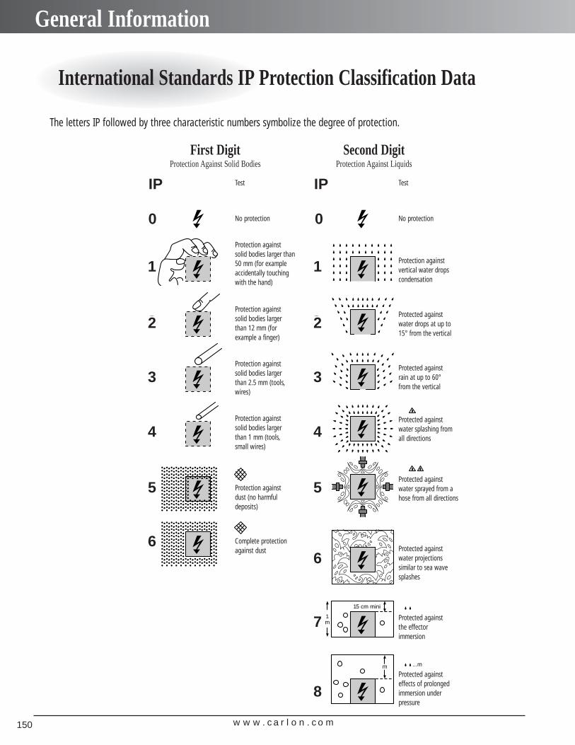
w w w . c a r l o n . c o m150
General Information
International Standards IP Protection Classification Data
The letters IP followed by three characteristic numbers symbolize the degree of protection.
1
2
3
4
5
6
0
Protected againstsolid bodies largerthan 50 mm (forexample acciden-tally touching with the hand)
No protection
Protected againstsolid bodies largerthan 12 mm (forexample a finger)
Protected againstsolid bodies largerthan 2.5 mm (tools,wires)
Protected againstsolid bodies largerthan 1 mm (fine tools, small wires)
Protected againstdust (no harmfuldeposits)
Complete protectionagainst dust
1
2
3
4
5
6
7
0
Protected againstvertical water drop(condensation)
No protection
Protected againstwater drops at up 15° from the vertic
Protected againstrain at up to 60° from the vertical
Protected againstwater splashing frall directions
Protected againstwater sprayed froma hose from alldirections
Protected againstwater projectionssimilar to sea wavsplashes
Protected againsteffects of prolongeimmersion underpressure
Protected againstthe effect ofimmersion
15 cm mini
1m
8
...mm
First DigitProtection Against Solid Bodies
Second DigitProtection Against Liquids
TestTest
No protection No protection
Protection againstvertical water dropscondensation
Protected againstwater drops at up to 15° from the vertical
Protected againstwater splashing fromall directions
Protected againstwater sprayed from ahose from all directions
Protected againstwater projections similar to sea wavesplashes
Protected against the effector immersion
Protected against effects of prolonged immersion under pressure
Protected againstrain at up to 60°from the vertical
Protection againstsolid bodies larger than50 mm (for exampleaccidentally touchingwith the hand)
Protection againstsolid bodies larger than 12 mm (for example a finger)
Protection againstsolid bodies larger than 2.5 mm (tools,wires)
Protection againstsolid bodies larger than 1 mm (tools,small wires)
Protection againstdust (no harmful deposits)
Complete protectionagainst dust
IP IP
0 0
1
2
3
4
5
6
1
2
3
4
5
6
7
8
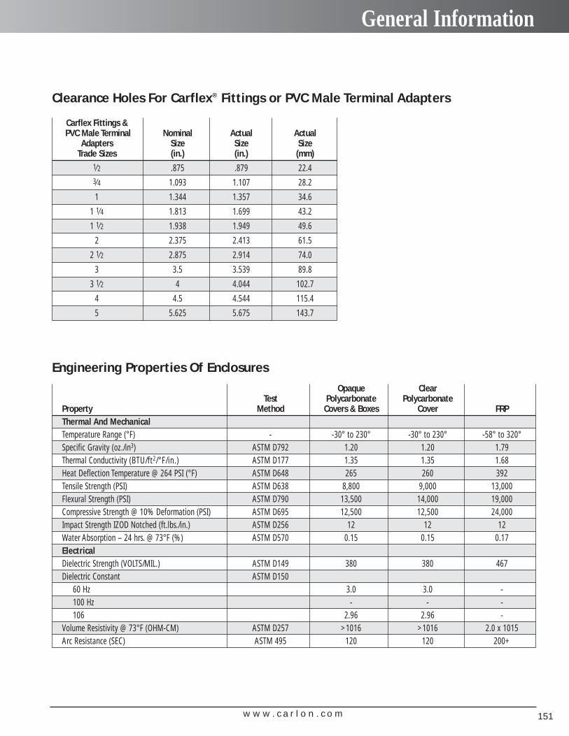
w w w . c a r l o n . c o m 151
General Information
Clearance Holes For Carflex® Fittings or PVC Male Terminal Adapters
Engineering Properties Of Enclosures
Carflex Fittings &PVC Male Terminal Nominal Actual Actual
Adapters Size Size SizeTrade Sizes (in.) (in.) (mm)
1⁄2 .875 .879 22.43⁄4 1.093 1.107 28.2
1 1.344 1.357 34.6
1 1⁄4 1.813 1.699 43.2
1 1⁄2 1.938 1.949 49.6
2 2.375 2.413 61.5
2 1⁄2 2.875 2.914 74.0
3 3.5 3.539 89.8
3 1⁄2 4 4.044 102.7
4 4.5 4.544 115.4
5 5.625 5.675 143.7
Opaque ClearTest Polycarbonate Polycarbonate
Property Method Covers & Boxes Cover FRPThermal And MechanicalTemperature Range (°F) - -30° to 230° -30° to 230° -58° to 320°Specific Gravity (oz./in3) ASTM D792 1.20 1.20 1.79Thermal Conductivity (BTU/ft2/°F/in.) ASTM D177 1.35 1.35 1.68Heat Deflection Temperature @ 264 PSI (°F) ASTM D648 265 260 392Tensile Strength (PSI) ASTM D638 8,800 9,000 13,000Flexural Strength (PSI) ASTM D790 13,500 14,000 19,000Compressive Strength @ 10% Deformation (PSI) ASTM D695 12,500 12,500 24,000Impact Strength IZOD Notched (ft.lbs./in.) ASTM D256 12 12 12Water Absorption – 24 hrs. @ 73°F (%) ASTM D570 0.15 0.15 0.17ElectricalDielectric Strength (VOLTS/MIL.) ASTM D149 380 380 467Dielectric Constant ASTM D150
60 Hz 3.0 3.0 -100 Hz - - -106 2.96 2.96 -
Volume Resistivity @ 73°F (OHM-CM) ASTM D257 >1016 >1016 2.0 x 10¹⁵Arc Resistance (SEC) ASTM 495 120 120 200+

w w w . c a r l o n . c o m152
General Information
Chemical Resistance DataEnvironmental Resistance Table: E–Excellent, G–Good, L–Limited, U–UnsatisfactoryThese environmental resistance ratings are based upon tests where the specimens were placed in complete submergence in the reagent listed. Inmany applications the Circuit Safe® and Himeline® boxes can be used in process areas where these chemicals are manufactured or used becauseworker safety requirements dictate that any air presence or splashing be at a very low level. Most electrical controls are located in areas suitable forworker access. If there are any questions for specific suitability in a given environment, prototype samples should be tested under actual conditions.
Chemical FRPPolycarbonate Fiberglass
ReinforcedPolyester
Acetaldehyde U -Acetate Solvents-Crude U -Acetate Solvents-Pure U -Acetic Acid 0-20% G EAcetic Acid 20-30% G EAcetic Acid 30-60% L EAcetic Acid 80% U EAcetic Acid-Glacial U EAcetic Acid Vapors L -Acetic Anhydride U EAcetone U UAllyl Alcohol 96% L -Allyl Chloride U UAlum L -AIuminum Chloride L EAluminum Fluoride E -Aluminum Hydroxide E -Aluminum Oxychloride E -Aluminum Nitrate E -Aluminum Sulfate E EAmmonia-Dry Gas U LAmmonia-Liquid U LAmmonium Bifluoride E -Ammonium Carbonate U LAmmonium Chloride L EAmmonium Hydroxide 25% U LAmmonium Metaphosphate E -Ammonium Nitrate E LAmmonium Persulfate E -Ammonium Phosphate-Neutral G EAmmonium Sulfate E EAmmonium Sulfide E EAmyl Acetate U LAmyl Alcohol L LAmyl Chloride U UAniline U UAniline Chlorohydrate U -Aniline Hydrochloride U -Antimony Trichloride E E
Barium Carbonate E EBarium Chloride E EBarium Hydroxide L UBarium Sulfate E EBarium Sulfide E EBenzaldehyde U UBenzene U LBenzene Sulfonic Acid 10% U EBenzol U -Bismuth Carbonate E -Bleach -12 57% Active CL 2/3 L -Borax L -Boric Acid E EBrine E -Bromic Acid U -Bromine-Liquid U UBromine-Water L -
Chemical FRPPolycarbonate Fiberglass
ReinforcedPolyester
Butane L -Butonal-Primary G -Butonal-Secondary G -Butyl Acetate U UButyl Alcohol G EButyl Phenol U -
Calcium Bisulfite G -Calcium Carbonate E ECalcium Chlorate G ECalcium Chloride E ECalcium Hydroxide U UCalcium Hypochlorite L LCalcium Nitrate E ECalcium Sulfate G ECarbon Bisulfide U LCarbon Dioxide Gas-Wet E -Carbon Dioxide E -Aqueous Solution E ECarbon Tetrachloride U EChlorine Water G EChlorobenzene U UChromic Acid 10% E ECitric Acid (5%) E ECresol U UCresylic Acid 5% U -Cyclohexanol U -Cyclohexanone U -
Demineralized Water E EDextrin E -Dextrose E -Dimethylamine U UDioctylphthalate U EDisodium Phosphate - -
Ethers U LEthyl Acetate U LEthyl Acrylate U -Ethyl Alcohol G GEthyl Chloride U LEthyl Ether U UEthylene Bromide U -Ethylene Chlorohydrin U EEthylene Dichloride U UEthylene Glycol E E
Ferric Chloride E EFerric Nitrate L EFerric Sulfate G EFerrous Chloride G EFerrous Sulfate E EFormaldehyde (37%) E EFormic Acid (45%) G LFreon L -Furfural U LGasoline-Sour U -Gasoline-Refined U EGlucose E E

w w w . c a r l o n . c o m 153
General Information
Chemical Resistance DataEnvironmental Resistance Table: E–Excellent, G–Good, L–Limited, U–UnsatisfactoryThese environmental resistance ratings are based upon tests where the specimens were placed in complete submergence in the reagent listed. Inmany applications the Circuit Safe® and Himeline® boxes can be used in process areas where these chemicals are manufactured or used becauseworker safety requirements dictate that any air presence or splashing be at a very low level. Most electrical controls are located in areas suitable forworker access. If there are any questions for specific suitability in a given environment, prototype samples should be tested under actual conditions.
Chemical FRPPolycarbonate Fiberglass
ReinforcedPolyester
Glycerine (Glycerol) E EGlycol G -
Heptane G EHexane G UHexanol Tertiary L -Hydrochloric Acid 0-25% G EHydrochloric Acid 25-40% U LHydrofluoric Acid 10% G EHydrofluoric Acid 48% U -Hydrogen Peroxide 30% U EHydrogen Peroxide 50% U EHydrogen Peroxide 90% U -Hydroquinone E -
Kerosene G E
Lactic Acid 28% E ELauryl Chloride G E
Magnesium Carbonate E EMagnesium Chloride E EMagnesium Hydroxide G GMagnesium Nitrate E -Magnesium Sulfate G EMethyl Alcohol G LMethyl Chloride U UMethyl Ethyl Ketone U EMethylene Chloride U UMineral Oils G -
Naphtha U ENitric Acid 20% E GNitrobenzene U L
Oleic Acid L EOxalic Acid (10%) G E
Phenol U LPhenylhydrazine U -Phosphoric Acid 0-25% L LPhosphoric Acid 25-50% U UPhosphoric Acid 50-85% U UPhosphoric Pentoxide G -Photographic Chemicals G -Potassium Bicarbonate E -Potassium Bichromate G -Potassium Borate E -Potassium Bromate E -Potassium Carbonate E LPotassium Chloride E EPotassium Chromate E EPotassium Cyanide E -Potassium Dichromate E -Potassium Ferricyanide E EPotassium Ferrocyanide E EPotassium Fluoride E -Potassium Hydroxide U LPotassium Nitrate E EPotassium Perborate L -
Chemical FRPPolycarbonate Fiberglass
ReinforcedPolyester
Potassium Permanganate 10% E EPotassium Persulfate E -Potassium Sulfate - EPropane G -Propyl Alcohol E EPropylene Dichloride U -
Sodium Acetate E ESodium Bicarbonate E ESodium Bisulfate E -Sodium Bisulfite E -Sodium Bromide E ESodium Chlorate E ESodium Chloride G ESodium Dichromate E ESodium Ferricyanide E ESodium Ferrocyanide E ESodium Fluoride E -Sodium Hydroxide U USodium Hypochlorite 12.5% U LSodium Nitrate E USodium Nitrite E ESodium Phosphate-Acid L ESodium Sulfate E ESodium Sulfide U USodium Sulfite E ESodium Thiosulfate (Hypo) L -Sulfur E ESulfur Dioxide-Gas Dry - -Sulfur Dioxide-Gas Wet U ESulfur Dioxide-Liquid U -Sulfuric Acid 0-10% E ESulfuric Acid 10-75% L U
Tartaric Acid E ETetrahydrofurane U LTitanium Tetrachloride G -Toluol or Toluene U -Tributyl Phosphate U -Trichloroethylene U UTricresylphosphate U -Triethanolamine U LTriethylamine U -Trimethyl Propane U -Trisodium Phosphate L -Turpentine U E
Urea G L
Vinegar G E
Whiskey L -Wines L -
Xylene or Xylol U E
Zinc Chloride U EZinc Chromate U -Zinc Nitrate L -Zinc Sulfate - E

w w w . c a r l o n . c o m154
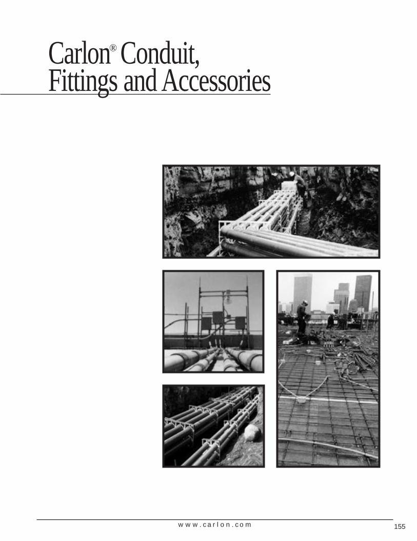
w w w . c a r l o n . c o m 155
Carlon® Conduit, Fittings and Accessories
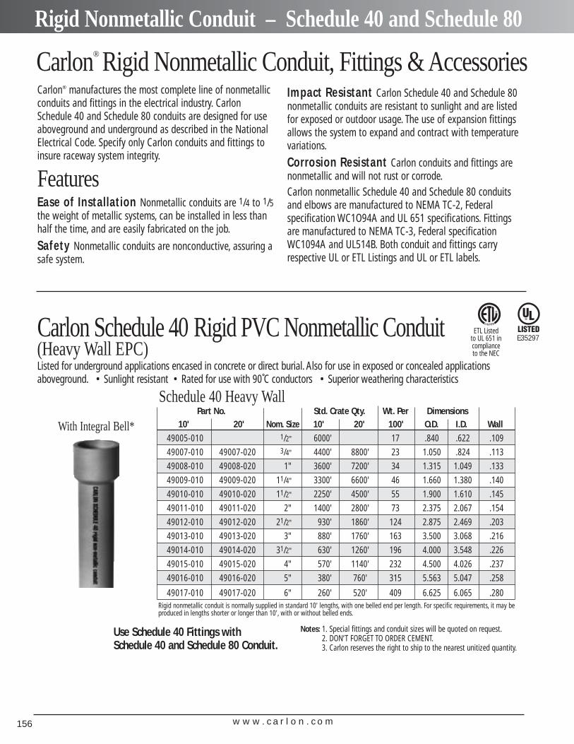
w w w . c a r l o n . c o m156
Rigid Nonmetallic Conduit – Schedule 40 and Schedule 80
Carlon® Rigid Nonmetallic Conduit, Fittings & AccessoriesCarlon® manufactures the most complete line of nonmetallicconduits and fittings in the electrical industry. CarlonSchedule 40 and Schedule 80 conduits are designed for useaboveground and underground as described in the NationalElectrical Code. Specify only Carlon conduits and fittings toinsure raceway system integrity.
FeaturesEase of Installation Nonmetallic conduits are 1/4 to 1/5the weight of metallic systems, can be installed in less thanhalf the time, and are easily fabricated on the job.
Safety Nonmetallic conduits are nonconductive, assuring asafe system.
Impact Resistant Carlon Schedule 40 and Schedule 80nonmetallic conduits are resistant to sunlight and are listedfor exposed or outdoor usage. The use of expansion fittingsallows the system to expand and contract with temperaturevariations.
Corrosion Resistant Carlon conduits and fittings arenonmetallic and will not rust or corrode.Carlon nonmetallic Schedule 40 and Schedule 80 conduitsand elbows are manufactured to NEMA TC-2, Federal specification WC1O94A and UL 651 specifications. Fittingsare manufactured to NEMA TC-3, Federal specificationWC1094A and UL514B. Both conduit and fittings carryrespective UL or ETL Listings and UL or ETL labels.
Part No. Std. Crate Qty. Wt. Per Dimensions10' 20' Nom. Size 10' 20' 100' O.D. I.D. Wall
49005-010 1/2" 6000' 17 .840 .622 .109
49007-010 49007-020 3/4" 4400' 8800' 23 1.050 .824 .113
49008-010 49008-020 1" 3600' 7200' 34 1.315 1.049 .133
49009-010 49009-020 11/4" 3300' 6600' 46 1.660 1.380 .140
49010-010 49010-020 11/2" 2250' 4500' 55 1.900 1.610 .145
49011-010 49011-020 2" 1400' 2800' 73 2.375 2.067 .154
49012-010 49012-020 21/2" 930' 1860' 124 2.875 2.469 .203
49013-010 49013-020 3" 880' 1760' 163 3.500 3.068 .216
49014-010 49014-020 31/2" 630' 1260' 196 4.000 3.548 .226
49015-010 49015-020 4" 570' 1140' 232 4.500 4.026 .237
49016-010 49016-020 5" 380' 760' 315 5.563 5.047 .258
49017-010 49017-020 6" 260' 520' 409 6.625 6.065 .280
With Integral Bell*
Carlon Schedule 40 Rigid PVC Nonmetallic Conduit(Heavy Wall EPC) Listed for underground applications encased in concrete or direct burial. Also for use in exposed or concealed applications aboveground. • Sunlight resistant • Rated for use with 90˚C conductors • Superior weathering characteristics
Schedule 40 Heavy Wall
Rigid nonmetallic conduit is normally supplied in standard 10' lengths, with one belled end per length. For specific requirements, it may beproduced in lengths shorter or longer than 10', with or without belled ends.
E35297ETL Listed
to UL 651 in complianceto the NEC
Use Schedule 40 Fittings with Schedule 40 and Schedule 80 Conduit.
Notes: 1. Special fittings and conduit sizes will be quoted on request.2. DON’T FORGET TO ORDER CEMENT.3. Carlon reserves the right to ship to the nearest unitized quantity.
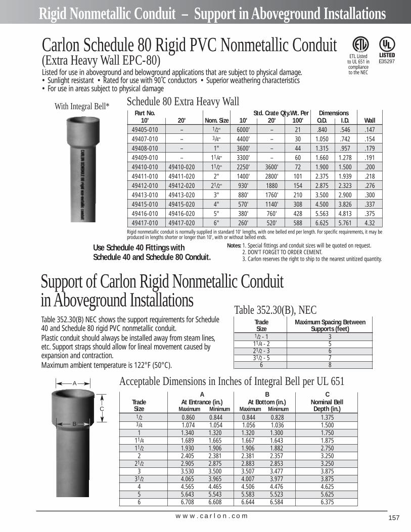
w w w . c a r l o n . c o m 157
Rigid Nonmetallic Conduit – Support in Aboveground Installations
Part No. Std. Crate Qty.Wt. Per Dimensions10' 20' Nom. Size 10' 20' 100' O.D. I.D. Wall
49405-010 – 1/2" 6000' – 21 .840 .546 .14749407-010 – 3/4" 4400' – 30 1.050 .742 .15449408-010 – 1" 3600' – 44 1.315 .957 .17949409-010 – 11/4" 3300' – 60 1.660 1.278 .19149410-010 49410-020 11/2" 2250' 3600' 72 1.900 1.500 .20049411-010 49411-020 2" 1400' 2800' 101 2.375 1.939 .21849412-010 49412-020 21/2" 930' 1880 154 2.875 2.323 .27649413-010 49413-020 3" 880' 1760' 210 3.500 2.900 .30049415-010 49415-020 4" 570' 1140' 308 4.500 3.826 .33749416-010 49416-020 5" 380' 760' 428 5.563 4.813 .37549417-010 49417-020 6" 260' 520' 588 6.625 5.761 4.32
With Integral Bell*
Use Schedule 40 Fittings with Schedule 40 and Schedule 80 Conduit.
Notes: 1. Special fittings and conduit sizes will be quoted on request.2. DON’T FORGET TO ORDER CEMENT.3. Carlon reserves the right to ship to the nearest unitized quantity.
Carlon Schedule 80 Rigid PVC Nonmetallic Conduit(Extra Heavy Wall EPC-80)Listed for use in aboveground and belowground applications that are subject to physical damage.• Sunlight resistant • Rated for use with 90˚C conductors • Superior weathering characteristics• For use in areas subject to physical damage
Schedule 80 Extra Heavy Wall
Rigid nonmetallic conduit is normally supplied in standard 10' lengths, with one belled end per length. For specific requirements, it may beproduced in lengths shorter or longer than 10', with or without belled ends.
Support of Carlon Rigid Nonmetallic Conduit in Aboveground InstallationsTable 352.30(B) NEC shows the support requirements for Schedule40 and Schedule 80 rigid PVC nonmetallic conduit.Plastic conduit should always be installed away from steam lines,etc. Support straps should allow for lineal movement caused byexpansion and contraction.Maximum ambient temperature is 122°F (50°C).
Table 352.30(B), NECTrade Maximum Spacing BetweenSize Supports (feet)
1/2 - 1 311/4 - 2 521/2 - 3 631/2 - 5 7
6 8
Acceptable Dimensions in Inches of Integral Bell per UL 651A B C
Trade At Entrance (in.) At Bottom (in.) Nominal BellSize Maximum Minimum Maximum Minimum Depth (in.)1/2 0.860 0.844 0.844 0.828 1.3753/4 1.074 1.054 1.056 1.036 1.5001 1.340 1.320 1.320 1.300 1.750
11/4 1.689 1.665 1.667 1.643 1.87511/2 1.930 1.906 1.906 1.882 2.750
2 2.405 2.381 2.381 2.357 3.25021/2 2.905 2.875 2.883 2.853 3.250
3 3.530 3.500 3.507 3.477 3.87531/2 4.065 3.965 4.007 3.977 3.875
4 4.565 4.465 4.506 4.476 4.6255 5.643 5.543 5.583 5.523 5.6256 6.708 6.608 6.644 6.584 6.375
A
B
C
E35297ETL Listed
to UL 651 in complianceto the NEC
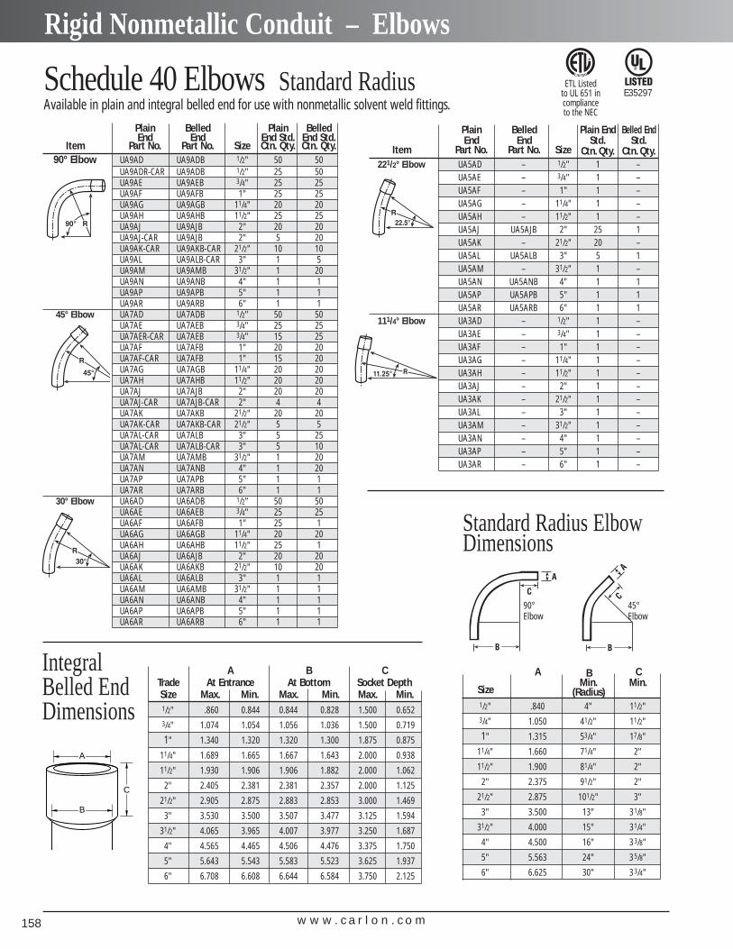
w w w . c a r l o n . c o m158
Rigid Nonmetallic Conduit – Elbows
Plain Belled Plain BelledEnd End End Std. End Std.
Item Part No. Part No. Size Ctn. Qty. Ctn. Qty.90° Elbow UA9AD UA9ADB 1/2" 50 50
UA9ADR-CAR UA9ADB 1/2" 25 50UA9AE UA9AEB 3/4" 25 25UA9AF UA9AFB 1" 25 25UA9AG UA9AGB 11/4" 20 20UA9AH UA9AHB 11/2" 25 25UA9AJ UA9AJB 2" 20 20UA9AJ-CAR UA9AJB 2" 5 20UA9AK-CAR UA9AKB-CAR 21/2" 10 10UA9AL UA9ALB-CAR 3" 1 5UA9AM UA9AMB 31/2" 1 20UA9AN UA9ANB 4" 1 1UA9AP UA9APB 5" 1 1UA9AR UA9ARB 6" 1 1
45° Elbow UA7AD UA7ADB 1/2" 50 50UA7AE UA7AEB 3/4" 25 25UA7AER-CAR UA7AEB 3/4" 15 25UA7AF UA7AFB 1" 20 20UA7AF-CAR UA7AFB 1" 15 20UA7AG UA7AGB 11/4" 20 20UA7AH UA7AHB 11/2" 20 20UA7AJ UA7AJB 2" 20 20UA7AJ-CAR UA7AJB-CAR 2" 4 4UA7AK UA7AKB 21/2" 20 20UA7AK-CAR UA7AKB-CAR 21/2" 5 5UA7AL-CAR UA7ALB 3" 5 25UA7AL-CAR UA7ALB-CAR 3" 5 10UA7AM UA7AMB 31/2" 1 20UA7AN UA7ANB 4" 1 20UA7AP UA7APB 5" 1 1UA7AR UA7ARB 6" 1 1
30° Elbow UA6AD UA6ADB 1/2" 50 50UA6AE UA6AEB 3/4" 25 25UA6AF UA6AFB 1" 25 1UA6AG UA6AGB 11/4" 20 20UA6AH UA6AHB 11/2" 25 1UA6AJ UA6AJB 2" 20 20UA6AK UA6AKB 21/2" 10 20UA6AL UA6ALB 3" 1 1UA6AM UA6AMB 31/2" 1 1UA6AN UA6ANB 4" 1 1UA6AP UA6APB 5" 1 1UA6AR UA6ARB 6" 1 1
Schedule 40 Elbows Standard Radius Available in plain and integral belled end for use with nonmetallic solvent weld fittings.
Plain Belled Plain End Belled EndEnd End Std. Std.
Item Part No. Part No. Size Ctn. Qty. Ctn. Qty.221/2° Elbow UA5AD – 1/2" 1 –
UA5AE – 3/4" 1 –UA5AF – 1" 1 –UA5AG – 11/4" 1 –UA5AH – 11/2" 1 –UA5AJ UA5AJB 2" 25 1UA5AK – 21/2" 20 –UA5AL UA5ALB 3" 5 1UA5AM – 31/2" 1 –UA5AN UA5ANB 4" 1 1UA5AP UA5APB 5" 1 1UA5AR UA5ARB 6" 1 1
111/4° Elbow UA3AD – 1/2" 1 –UA3AE – 3/4" 1 –UA3AF – 1" 1 –UA3AG – 11/4" 1 –UA3AH – 11/2" 1 –UA3AJ – 2" 1 –UA3AK – 21/2" 1 –UA3AL – 3" 1 –UA3AM – 31/2" 1 –UA3AN – 4" 1 –UA3AP – 5" 1 –UA3AR – 6" 1 –
A B CMin. Min.
Size (Radius)1/2" .840 4" 11/2"3/4" 1.050 41/2" 11/2"
1" 1.315 53/4" 17/8"
11/4" 1.660 71/4" 2"
11/2" 1.900 81/4" 2"
2" 2.375 91/2" 2"
21/2" 2.875 101/2" 3"
3" 3.500 13" 31/8"
31/2" 4.000 15" 31/4"
4" 4.500 16" 33/8"
5" 5.563 24" 35/8"
6" 6.625 30" 33/4"
A B CTrade At Entrance At Bottom Socket DepthSize Max. Min. Max. Min. Max. Min.1/2" .860 0.844 0.844 0.828 1.500 0.6523/4" 1.074 1.054 1.056 1.036 1.500 0.719
1" 1.340 1.320 1.320 1.300 1.875 0.875
11/4" 1.689 1.665 1.667 1.643 2.000 0.938
11/2" 1.930 1.906 1.906 1.882 2.000 1.062
2" 2.405 2.381 2.381 2.357 2.000 1.125
21/2" 2.905 2.875 2.883 2.853 3.000 1.469
3" 3.530 3.500 3.507 3.477 3.125 1.594
31/2" 4.065 3.965 4.007 3.977 3.250 1.687
4" 4.565 4.465 4.506 4.476 3.375 1.750
5" 5.643 5.543 5.583 5.523 3.625 1.937
6" 6.708 6.608 6.644 6.584 3.750 2.125
Standard Radius Elbow Dimensions
A
C
B
IntegralBelled EndDimensions
90°Elbow
45°Elbow
E35297ETL Listed
to UL 651 in complianceto the NEC
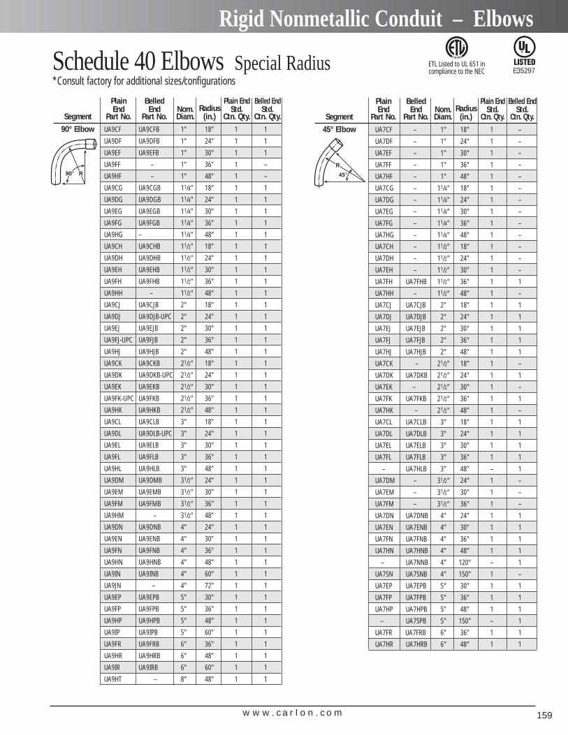
w w w . c a r l o n . c o m 159
Rigid Nonmetallic Conduit – Elbows
Schedule 40 Elbows Special Radius *Consult factory for additional sizes/configurations
Plain Belled Plain End Belled EndEnd End Nom. Radius Std. Std.
Segment Part No. Part No. Diam. (in.) Ctn. Qty. Ctn. Qty.
90° Elbow UA9CF UA9CFB 1" 18" 1 1
UA9DF UA9DFB 1" 24" 1 1
UA9EF UA9EFB 1" 30" 1 1
UA9FF – 1" 36" 1 –
UA9HF – 1" 48" 1 –
UA9CG UA9CGB 11/4" 18" 1 1
UA9DG UA9DGB 11/4" 24" 1 1
UA9EG UA9EGB 11/4" 30" 1 1
UA9FG UA9FGB 11/4" 36" 1 1
UA9HG – 11/4" 48" 1 1
UA9CH UA9CHB 11/2" 18" 1 1
UA9DH UA9DHB 11/2" 24" 1 1
UA9EH UA9EHB 11/2" 30" 1 1
UA9FH UA9FHB 11/2" 36" 1 1
UA9HH – 11/2" 48" 1 1
UA9CJ UA9CJB 2" 18" 1 1
UA9DJ UA9DJB-UPC 2" 24" 1 1
UA9EJ UA9EJB 2" 30" 1 1
UA9FJ-UPC UA9FJB 2" 36" 1 1
UA9HJ UA9HJB 2" 48" 1 1
UA9CK UA9CKB 21/2" 18" 1 1
UA9DK UA9DKB-UPC 21/2" 24" 1 1
UA9EK UA9EKB 21/2" 30" 1 1
UA9FK-UPC UA9FKB 21/2" 36" 1 1
UA9HK UA9HKB 21/2" 48" 1 1
UA9CL UA9CLB 3" 18" 1 1
UA9DL UA9DLB-UPC 3" 24" 1 1
UA9EL UA9ELB 3" 30" 1 1
UA9FL UA9FLB 3" 36" 1 1
UA9HL UA9HLB 3" 48" 1 1
UA9DM UA9DMB 31/2" 24" 1 1
UA9EM UA9EMB 31/2" 30" 1 1
UA9FM UA9FMB 31/2" 36" 1 1
UA9HM – 31/2" 48" 1 1
UA9DN UA9DNB 4" 24" 1 1
UA9EN UA9ENB 4" 30" 1 1
UA9FN UA9FNB 4" 36" 1 1
UA9HN UA9HNB 4" 48" 1 1
UA9IN UA9INB 4" 60" 1 1
UA9JN – 4" 72" 1 1
UA9EP UA9EPB 5" 30" 1 1
UA9FP UA9FPB 5" 36" 1 1
UA9HP UA9HPB 5" 48" 1 1
UA9IP UA9IPB 5" 60" 1 1
UA9FR UA9FRB 6" 36" 1 1
UA9HR UA9HRB 6" 48" 1 1
UA9IR UA9IRB 6" 60" 1 1
UA9HT – 8" 48" 1 1
Plain Belled Plain End Belled EndEnd End Nom. Radius Std. Std.
Segment Part No. Part No. Diam. (in.) Ctn. Qty. Ctn. Qty.
45° Elbow UA7CF – 1" 18" 1 –
UA7DF – 1" 24" 1 –
UA7EF – 1" 30" 1 –
UA7FF – 1" 36" 1 –
UA7HF – 1" 48" 1 –
UA7CG – 11/4" 18" 1 –
UA7DG – 11/4" 24" 1 –
UA7EG – 11/4" 30" 1 –
UA7FG – 11/4" 36" 1 –
UA7HG – 11/4" 48" 1 –
UA7CH – 11/2" 18" 1 –
UA7DH – 11/2" 24" 1 –
UA7EH – 11/2" 30" 1 –
UA7FH UA7FHB 11/2" 36" 1 1
UA7HH – 11/2" 48" 1 –
UA7CJ UA7CJB 2" 18" 1 1
UA7DJ UA7DJB 2" 24" 1 1
UA7EJ UA7EJB 2" 30" 1 1
UA7FJ UA7FJB 2" 36" 1 1
UA7HJ UA7HJB 2" 48" 1 1
UA7CK – 21/2" 18" 1 –
UA7DK UA7DKB 21/2" 24" 1 1
UA7EK – 21/2" 30" 1 –
UA7FK UA7FKB 21/2" 36" 1 1
UA7HK – 21/2" 48" 1 –
UA7CL UA7CLB 3" 18" 1 1
UA7DL UA7DLB 3" 24" 1 1
UA7EL UA7ELB 3" 30" 1 1
UA7FL UA7FLB 3" 36" 1 1
– UA7HLB 3" 48" – 1
UA7DM – 31/2" 24" 1 –
UA7EM – 31/2" 30" 1 –
UA7FM – 31/2" 36" 1 –
UA7DN UA7DNB 4" 24" 1 1
UA7EN UA7ENB 4" 30" 1 1
UA7FN UA7FNB 4" 36" 1 1
UA7HN UA7HNB 4" 48" 1 1
– UA7NNB 4" 120" – 1
UA7SN UA7SNB 4" 150" 1 –
UA7EP UA7EPB 5" 30" 1 1
UA7FP UA7FPB 5" 36" 1 1
UA7HP UA7HPB 5" 48" 1 1
– UA7SPB 5" 150" – 1
UA7FR UA7FRB 6" 36" 1 1
UA7HR UA7HRB 6" 48" 1 1
E35297ETL Listed to UL 651 in compliance to the NEC
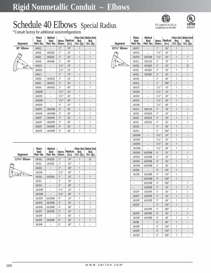
w w w . c a r l o n . c o m160
Rigid Nonmetallic Conduit – Elbows
Schedule 40 Elbows Special Radius *Consult factory for additional sizes/configurations
Plain Belled Plain End Belled EndEnd End Nom. Radius Std. Std.
Segment Part No. Part No. Diam. (in.) Ctn. Qty. Ctn. Qty.
30° Elbow UA6CJ – 2" 18" 1 –
UA6DJ UA6DJB 2" 24" 1 1
UA6FJ UA6FJB 2" 36" 1 1
UA6HJ UA6HJB 2" 48" 1 1
UA6CK – 21/2" 18" 1 –
UA6DK – 21/2" 24" 1 –
UA6CL – 3" 18" 1 –
UA6DL UA6DLB 3" 24" 1 1
UA6FL UA6FLB 3" 36" 1 1
UA6HL UA6HLB 3" 48" 1 1
UA6DM – 31/2" 24" 1 –
UA6FM – 31/2" 36" 1 –
UA6HM – 31/2" 48" 1 –
UA6DN – 4" 24" 1 –
UA6FN UA6FNB 4" 36" 1 1
UA6HN UA6HNB 4" 48" 1 1
UA6FP UA6FPB 5" 36" 1 1
UA6HP UA6HPB 5" 48" 1 1
UA6FR UA6FRB 6" 36" 1 1
UA6HR UA6HRB 6" 48" 1 1
Plain Belled Plain End Belled EndEnd End Nom. Radius Std. Std.
Segment Part No. Part No. Diam. (in.) Ctn. Qty. Ctn. Qty.
111/4° Elbow UA3DJ UA3DJB 2" 24" 1 25
UA3FJ UA3FJB 2" 36" 1 1
UA3HJ – 2" 48" 1 –
UA3HK – 21/2" 48" 1 –
UA3DL UA3DLB 3" 24" 1 1
UA3FL – 3" 36" 1 –
UA3HL – 3" 48" 1 –
UA3DM – 31/2" 24" 1 –
UA3HM – 31/2" 48" 1 –
UA3DN UA3DNB 4" 24" 1 1
UA3FN UA3FNB 4" 36" 1 1
UA3HN UA3HNB 4" 48" 1 1
UA3FP UA3FPB 5" 36" 1 1
UA3HP – 5" 48" 1 –
UA3FR UA3FRB 6" 36" 1 1
UA3HR – 6" 48" 1 –
Plain Belled Plain End Belled EndEnd End Nom. Radius Std. Std.
Segment Part No. Part No. Diam. (in.) Ctn. Qty. Ctn. Qty.
221/2° Elbow UA5FF – 1" 36" 1 –
UA5FG – 11/4" 36" 1 –
UA5FH UA5FHB 11/2" 36" 1 1
UA5CJ UA5CJB 2" 18" 1 1
UA5DJ UA5DJB 2" 24" 1 25
UA5EJ UA5EJB 2" 30" 1 1
UA5FJ UA5FJB 2" 36" 1 1
UA5HJ – 2" 48" 1 –
UA5VJ – 2" 300" 1 –
UA5CK – 21/2" 18" 1 –
UA5DK – 21/2" 24" 1 –
UA5EK – 21/2" 30" 1 –
UA5FK – 21/2" 36" 1 –
UA5HK – 21/2" 48" 1 –
UA5CL UA5CLB 3" 18" 1 1
UA5DL UA5DLB 3" 24" 1 1
UA5EL UA5ELB 3" 30" 1 1
UA5FL UA5FLB 3" 36" 1 1
UA5HL – 3" 48" 1 –
UA5VL – 3" 300" 1 –
UA5DM – 31/2" 24" 1 –
UA5EM – 31/2" 30" 1 –
UA5FM – 31/2" 36" 1 –
UA5HM – 31/2" 48" 1 –
UA5DN UA5DNB 4" 24" 1 1
UA5EN UA5ENB 4" 30" 1 1
UA5FN UA5FNB 4" 36" 1 1
UA5HN UA5HNB 4" 48" 1
UA5IN – 4" 60" 1
UA5SN UA5SNB 4" 150" 1
– UA5UNB 4" 240" 1
– UA5VNB 4" 300" – 1
– UA5DPB 5" 24" 1 1
UA5EP UA5EPB 5" 30" 1 1
UA5FP UA5FPB 5" 36" 1 1
UA5HP UA5HPB 5" 48" 1 1
UA5SP – 5" 150" 1 –
– UA5VPB 5" 300" – 1
UA5FR UA5FRB 6" 36" 1 1
UA5HR UA5HRB 6" 48" 1 1
UA5IR – 6" 60" 1 –
UA5RR – 6" 144" 1 –
UA5SR – 6" 150" 1 –
UA5VR – 6" 300" 1 –
E35297ETL Listed to UL 651 in compliance to the NEC
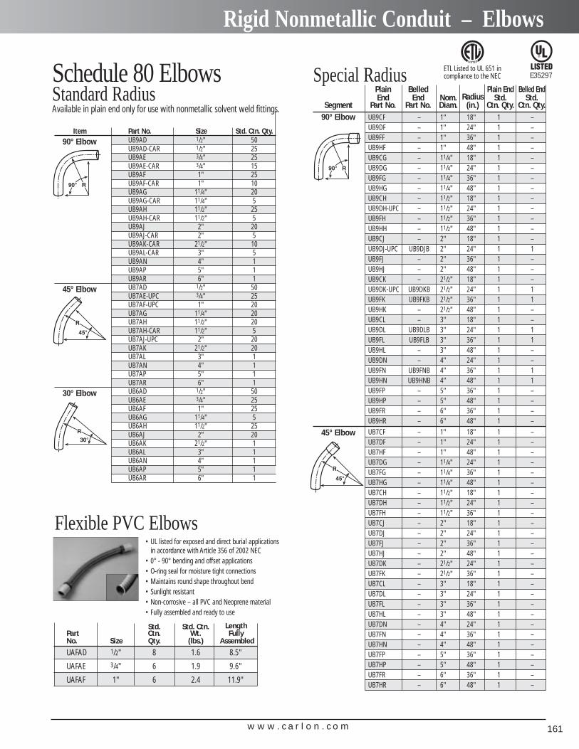
w w w . c a r l o n . c o m 161
Rigid Nonmetallic Conduit – Elbows
Schedule 80 ElbowsStandard RadiusAvailable in plain end only for use with nonmetallic solvent weld fittings.
Special RadiusPlain Belled Plain End Belled EndEnd End Nom. Radius Std. Std.
Segment Part No. Part No. Diam. (in.) Ctn. Qty. Ctn. Qty.90° Elbow UB9CF – 1" 18" 1 –
UB9DF – 1" 24" 1 –UB9FF – 1" 36" 1 –UB9HF – 1" 48" 1 –UB9CG – 11/4" 18" 1 –UB9DG – 11/4" 24" 1 –UB9FG – 11/4" 36" 1 –UB9HG – 11/4" 48" 1 –UB9CH – 11/2" 18" 1 –UB9DH-UPC – 11/2" 24" 1 –UB9FH – 11/2" 36" 1 –UB9HH – 11/2" 48" 1 –UB9CJ – 2" 18" 1 –UB9DJ-UPC UB9DJB 2" 24" 1 1UB9FJ – 2" 36" 1 –UB9HJ – 2" 48" 1 –UB9CK – 21/2" 18" 1 –UB9DK-UPC UB9DKB 21/2" 24" 1 1UB9FK UB9FKB 21/2" 36" 1 1UB9HK – 21/2" 48" 1 –UB9CL – 3" 18" 1 –UB9DL UB9DLB 3" 24" 1 1UB9FL UB9FLB 3" 36" 1 1UB9HL – 3" 48" 1 –UB9DN – 4" 24" 1 –UB9FN UB9FNB 4" 36" 1 1UB9HN UB9HNB 4" 48" 1 1UB9FP – 5" 36" 1 –UB9HP – 5" 48" 1 –UB9FR – 6" 36" 1 –UB9HR – 6" 48" 1 –
45° Elbow UB7CF – 1" 18" 1 –UB7DF – 1" 24" 1 –UB7HF – 1" 48" 1 –UB7DG – 11/4" 24" 1 –UB7FG – 11/4" 36" 1 –UB7HG – 11/4" 48" 1 –UB7CH – 11/2" 18" 1 –UB7DH – 11/2" 24" 1 –UB7FH – 11/2" 36" 1 –UB7CJ – 2" 18" 1 –UB7DJ – 2" 24" 1 –UB7FJ – 2" 36" 1 –UB7HJ – 2" 48" 1 –UB7DK – 21/2" 24" 1 –UB7FK – 21/2" 36" 1 –UB7CL – 3" 18" 1 –UB7DL – 3" 24" 1 –UB7FL – 3" 36" 1 –UB7HL – 3" 48" 1 –UB7DN – 4" 24" 1 –UB7FN – 4" 36" 1 –UB7HN – 4" 48" 1 –UB7FP – 5" 36" 1 –UB7HP – 5" 48" 1 –UB7FR – 6" 36" 1 –UB7HR – 6" 48" 1 –
Item Part No. Size Std. Ctn. Qty.90° Elbow UB9AD 1/2" 50
UB9AD-CAR 1/2" 25UB9AE 3/4" 25UB9AE-CAR 3/4" 15UB9AF 1" 25UB9AF-CAR 1" 10UB9AG 11/4" 20UB9AG-CAR 11/4" 5UB9AH 11/2" 25UB9AH-CAR 11/2" 5UB9AJ 2" 20UB9AJ-CAR 2" 5UB9AK-CAR 21/2" 10UB9AL-CAR 3" 5UB9AN 4" 1UB9AP 5" 1UB9AR 6" 1
45° Elbow UB7AD 1/2" 50UB7AE-UPC 3/4" 25UB7AF-UPC 1" 20UB7AG 11/4" 20UB7AH 11/2" 20UB7AH-CAR 11/2" 5UB7AJ-UPC 2" 20UB7AK 21/2" 20UB7AL 3" 1UB7AN 4" 1UB7AP 5" 1UB7AR 6" 1
30° Elbow UB6AD 1/2" 50UB6AE 3/4" 25UB6AF 1" 25UB6AG 11/4" 5UB6AH 11/2" 25UB6AJ 2" 20UB6AK 21/2" 1UB6AL 3" 1UB6AN 4" 1UB6AP 5" 1UB6AR 6" 1
Flexible PVC Elbows
Std. Std. Ctn. LengthPart Ctn. Wt. FullyNo. Size Qty. (lbs.) Assembled
UAFAD 1/2" 8 1.6 8.5"
UAFAE 3/4" 6 1.9 9.6"
UAFAF 1" 6 2.4 11.9"
▲
• UL listed for exposed and direct burial applicationsin accordance with Article 356 of 2002 NEC
• 0° - 90° bending and offset applications• O-ring seal for moisture tight connections• Maintains round shape throughout bend• Sunlight resistant• Non-corrosive – all PVC and Neoprene material• Fully assembled and ready to use
E35297ETL Listed to UL 651 in compliance to the NEC
w w w . c a r l o n . c o m162
Rigid Nonmetallic Conduit – Couplings
Std.Part Ctn. A B C LNo. Size Qty. Typical I.D. O.D. Typical
E940D 1/2 150 .852 .836 .728 17/64 11/16 11/2
E940E 3/4 100 1.064 1.046 .840 15/16 3/4 15/8
E940F 1 50 1.330 1.310 1.210 15/8 15/16 2
E940G 11/4 30 1.677 1.655 1.535 163/64 1 21/8
E940H 11/2 25 1.918 1.894 1.755 215/64 11/8 23/8
E940J 2 30 2.393 2.369 2.190 247/64 13/16 21/2
E940K 21/2 20 2.890 2.868 2.688 35/16 133/64 33/16
E940K-CAR 21/2 4 2.890 2.868 2.688 35/16 133/64 33/16
E940L 3 25 3.515 3.492 3.375 331/32 13/4 313/32
E940L-CAR 3 5 3.515 3.492 3.375 331/32 13/4 313/32
E940M 31/2 20 4.015 3.992 3.780 49/16 13/4 35/8
E940N 4 15 4.515 4.491 4.265 53/32 125/32 33/4
E940N-CAR 4 5 4.515 4.491 4.265 53/32 125/32 33/4
E940P 5 8 5.593 5.553 5.097 61/4 15/16 41/16
E940R 6 5 6.658 6.614 6.115 71/2 23/16 45/8
All socket fittings should be attached Using Carlon solvent cement. Using Carlon fittings with Carlon nonmetallic conduit insures system integrity.
Standard Couplings
Socket type for joining nonmetallic conduit.
Special Long Line Couplings Std. Std. Ctn.
Part No. Size Ctn. Qty. Wt. (lbs.)E941H 11/2 40 9E941J 2 25 8E941K 21/2 15 8E941L 3 15 14E941N 4 10 15E941PF 5 4 12E941RF 6 5 21
▲
Long LineCouplings
Couplings E32447
Except where noted by
▲
Short Expansion Couplings (Expands to a maximum of 2") Std.
Part No. Size Ctn. Qty.
E955D 1/2 40E955E 3/4 40E955F 1 25E955G 11/4 15E955H 11/2 10E955J 2 6
E33447
E32447
Expansion Couplings (For Use with Schedule 40 and Schedule 80)E945 series expansion couplings are designed to compensate for length changes due to temperature variations in exposedconduit runs.
Standard Expansion Couplings (Expands to a maximum of 6")
Lay LengthsStd. Stop to Stop Stop to Stop
Part No. Size Ctn. Qty. Total Closed Total OpenE945D 1/2 50 121/4 18 5/8E945E 3/4 50 121/4 18 5/8E945F 1 45 123/4 19 1/8E945G 11/4 30 123/4 19 1/8E945H 11/2 25 123/4 19 1/8E945J 2 15 131/2 19 7/8E945K 21/2 10 14 20 3/8
E945KX 21/2 10 14 63/100 20 81/100(with male adapter)
E945KXL 21/2 10 24 36(special 12 trav)
E945L 3 10 161/2 23 E945LX 3 10 15 9/10 221/3(with male adapter)
E945M 31/2 5 161/2 23E945N 4 5 171/2 24E945P 5 3 181/2 24 1/2E945R 6 2 201/2 261/2
w w w . c a r l o n . c o m 163
Rigid Nonmetallic Conduit – Adapters
Part Std. A B Min. Max. C S LNo. Size Ctn. Qty. Typical D OD Typical
E943D 1/2 150 .852 .836 .597 11/8 5/8 9/16 15/16
E943E 3/4 125 1.064 1.046 .800 111/32 3/4 9/16 13/8E943F 1 50 1.330 1.310 1.018 15/8 1 11/16 125/32
E943G 11/4 50 1.677 1.655 1.332 21/32 1 3/4 115/16
E943H 11/2 25 1.918 1.894 1.566 2 5/32 13/16 3/4 21/16
E943J 2 50 2.393 2.369 2.000 2 21/32 13/16 3/4 21/8E943K 21/2 25 2.890 2.868 2.376 3 5/16 13/4 7/8 27/8E943K-CAR 21/2 5 2.890 2.868 2.376 3 5/16 13/4 7/8 27/8E943L 3 45 3.515 3.492 2.954 4 115/16 7/8 31/16
E943L-CAR 3 5 3.515 3.492 2.954 4 115/16 7/8 31/16
E943M 31/2 30 4.015 3.992 3.440 41/2 27/16 17/8 37/16
E943N 4 20 4.515 4.491 3.940 53/32 23/8 7/8 31/2E943N-CAR 4 20 4.515 4.491 3.940 53/32 23/8 7/8 31/2E943P 5 5 5.593 5.553 4.815 61/4 21/3 1 315/16
E943R 6 10 6.658 6.614 5.860 71/2 23/8 1 33/8
Male Terminal AdaptersFor adapting nonmetallicconduits to boxes, threadedfittings, metallic systems.Male threads on one end,socket end on other.
Part Std. A B Min. Max. C T LNo. Size Ctn. Qty. Typical D OD TypicalE942D 1/2 150 .852 .836 .620 17/64 11/16 3/4 19/16
E942E 3/4 100 1.064 1.046 .822 15/16 13/16 3/4 15/8E942F 1 50 1.330 1.310 1.046 15/8 15/16 7/8 115/16
E942G 11/4 30 1.677 1.655 1.377 163/64 1 7/8 2E942H 11/2 25 1.918 1.894 1.607 25/32 11/8 7/8 27/32
E942J 2 30 2.393 2.369 2.064 247/64 13/16 1 25/16
E942K 21/2 20 2.890 2.868 2.450 311/32 15/8 11/8 215/16
E942K-CAR 21/2 4 2.890 2.868 2.450 311/32 15/8 11/8 215/16
E942L 3 25 3.515 3.492 3.000 331/32 13/4 11/8 31/16
E942L-CAR 3 3 3.515 3.492 3.000 331/32 13/4 11/8 31/16
E942M 31/2 20 4.015 3.992 3.500 41/2 17/8 11/8 31/4E942N 4 15 4.515 4.491 4.000 51/64 2 11/8 313/64
E942N-CAR 4 7 4.515 4.491 4.000 51/64 2 11/8 313/64
E942NX* 4 6E942P 5 8 5.593 5.553 5.047 61/4 115/16 11/16 33/16
E942R 6 6 6.658 6.614 6.055 71/4 21/8 11/16 33/8E942RX* 6 6 (Cal l for information)
Female Adapters
For adapting nonmetallicconduits to threaded fittings, metallic systems.Female threads on one end,socket end on other.
* Long Line Adapter
Adapters
(Cal l for information)
Special Schedule 40 Swedge Couplings*Consult factory for additional sizes
Std. Std. Ctn.Part No. Size Ctn. Qty. Wt. (lbs.)
E442K 21/2 20 13E442R 6 6 27E442T 8 2 17
▲▲
▲
RisersSchedule 40
Part A B C Thread Std. Std. Ctn.No. Size (Length) (Min.) Size Ctn. Qty. Wt. (lbs.)
E954HX 11/2 80.00 1.567 .950 11/2"NPT 1 3.8
E954J 2 60.00 2.024 .825 2"NPT 1 3.7
E954JX 2 80.00 2.024 .825 2"NPT 1 5.0
E954K 21/2 60.00 2.418 .812 21/2"NPSC 1 6.0
E954KX 21/2 80.00 2.418 .812 21/2"NPSC 1 8.4
E954L 3 60.00 3.012 .798 3"NPSC 1 8.7
E954LX 3 80.00 3.012 .798 3"NPSC 1 11.0
Std. Std. Ctn.Part No. Size Ctn. Qty. Wt. (lbs.)
E948H 11/2 25 6E948J 2 25 5E948K 21/2 25 16E948L 3 25 13E948N 4 10 8E948P 5 14 33E948R 6 6 16E948JR 2" (6" long) 15 8E948JS 2" (Sch. 40 Split Duct) 25 6E948L12 3" (12" long) 1 1E948L6 3" (6" long) 15 15E948LS 3" (Sch. 40 Split Duct) 25 17E948N12 4" (12" long) 10 28E948N7 4" (7" long) 15 25E948NS 4" (Sch. 40 Split Duct) 10 15E948PS 5" (Sch. 40 Split Duct) 1 2E948R10 6" (10" long) 6 25E948RS 6" (Sch. 40 Split Duct) 1 2
Special Long Line Couplings —
Sleeve Couplings
Couplings
Sleeve Coupling (For Repair Work)No Internal Stop
▲▲
▲▲
▲▲
▲▲
▲▲
▲▲
▲▲
▲▲
▲▲
E32447Except where noted by
▲
w w w . c a r l o n . c o m164
Rigid Nonmetallic Conduit – Special Application Fittings & Accessories
Part Std. Ctn. L A CNo. Size Qty. Typical Typical Typical
E950ED 3/4" x 1/2" 100 15/32 13/64 11/32
E950FD-CAR 1" x 1/2" 25 111/32 3/16 57/64
E950FE 1" x 3/4" 100 111/32 3/16 11/64
E950GE-CAR 11/4" x 3/4" 10 115/32 3/16 11/64
E950GF 11/4" x 1" 50 115/32 3/16 19/64
E950HF-CAR 11/2" x 1" 10 119/32 3/16 19/64
E950HG-CAR 11/2" x 11/4" 10 119/32 3/16 117/64
E950JG-CAR 2" x 11/4" 10 13/4 7/32 117/64
E950JH-CAR 2" x 11/2" 10 13/4 7/32 125/64
E950KJ-CAR 21/2" x 2" 10 25/32 3/8 127/64
E950LJ-CAR 3" x 2" 10 21/8 1/4 17/8E950LK 3" x 21/2" 25 115/16 1/4 111/16
E950NL 4" x 3" 25 23/4 5/16 115/16
Reducer BushingsFor connecting different sizesof conduit. Bell x Spigot.
Reducer PlugsStd. Std. Ctn.
Part No. Size Ctn. Qty. Wt. (lbs.)E971C 3/4" x 1/2" 100 2
E971D 1" x 3/4" 100 3
PlugsStd. Std. Ctn.
Part No. Size Ctn. Qty. Wt. (lbs.)P258H 11/2" 50 2
P258K 21/2" 25 1.5
▲▲
▲▲
Plugs with Pull TabsStd. Std. Ctn.
Part No. Size Ctn. Qty. Wt. (lbs.)P258JT 2 60 3
P258LT 3 30 3
P258NT 4 48 8
P258PT 5 30 6
P258RT 6 30 9
▲▲
▲▲
▲
Reducers
Plugs
E32447Except where noted by
▲
Part Std. Ctn. Min OD Max CM LNo. Size Qty. D Typical X Typical
E996D 1/2 100 .662 .840 17/64 23/32 27/32
E996E 3/4 100 .824 1.050 121/64 25/32 29/32
E996F 1 100 1.049 1.315 15/8 61/64 13/32
E996G 11/4 50 1.380 1.660 131/32 11/16 11/4E996H 11/2 50 1.610 1.900 213/64 13/16 13/8E996J 2 25 2.067 2.375 229/32 11/4 17/16
E996K-CAR 21/2 10 2.469 2.875 37/16 17/8 115/16
E996L 3 20 3.068 3.500 41/8 2 2 1/16
E996L-CAR 3 5 3.068 3.500 41/8 2 2 1/16
E996N 4 10 4.026 4.500 51/8 21/2 21/4
Box Adapters for Enclosures Adapts nonmetallic
conduit to all electricalenclosures by insertingadapter through knockoutand cementing into Carloncouplings.
Threaded AdaptersStd.
Part No. Size Ctn. Qty.
E9842D 1 1/2 25
E9842E 2 3/4 25
1 Fits 3/4" sockets 2 Fits 1" sockets
▲
Fabricated ReducersStd. Std. Ctn.
Part No. Size Ctn. Qty. Wt. (lbs.)E952KJ 21/2" x 2" 48 28
E952LJ 3" x 2" 36 21
E952LK 3" x 21/2" 36 31
E952NL 4" x 3" 15 23
E952NM 4" x 31/2" 15 25
E952PN 5" x 4" 12 26
E952RP 6" x 5" 10 31
▲▲
▲▲
▲▲
▲
Fabricated Reducers
(Male x Male)
Reducers Adapters
w w w . c a r l o n . c o m 165
Rigid Nonmetallic Conduit – Special Application Fittings & Accessories
End Bells
Offset Std.Std. Ctn. Qty.
Part No. Size Ctn. Qty. Wt. (lbs.)
E994DR-CAR 1/2 25 3
E994ER-CAR 3/4 15 2
E994F 1 50 12
▲▲
▲
EndBells
Std. Std.Ctn. Ctn.
Part No. Size Qty. Wt. (lbs.)E997F 1 50 1E997F-CAR 1 15 1E997G 11/4 35 1E997G-CAR 11/4 15 1E997H 11/2 30 1E997H-CAR 11/2 10 1E997J 2 40 1E997J-CAR 2 10 1E997K 21/2 30 2E997K-CAR 21/2 10 2E997L 3 50 2E997L-CAR 3 10 2E997M 31/2 40 10E997N 4 30 11E997P 5 15 10E997R 6 10 7.4E997T 8 3 14.55
▲▲
▲▲
▲▲
▲▲
▲▲
▲▲
▲▲
▲▲
▲
Part Std. Std.No. Size Ctn. Qty. Wt. (lbs.)
E949J5 2" x 5" 50 10E949J6 2" x 6" 25 12E949JN 2" x 4" 25 7E949JX 2" x 8" 12 7E949LR 3" x 6" 20 21E949N5 4" x 5" 20 2E949NR 4" x 6" 15 21E949R5 6" x 5" 12 27E949RX 6" x 8" 6 17
Fabricated End BellsSchedule 40
Meter OffsetStd.
Part No. Size Ctn. Qty. Offset A
E995G 11/4 15 0.758 4.230
E995J 2 8 0.684 4.270
▲▲
Offsets E32447Except where noted by
▲CapsService Entrance Caps
Std.Ctn. Number of Openings
Part No. Size Qty. 4 3 2 1E998E-CAR 3/4 5 – .430 – –E998F-CAR 1 5 .555 – – –E998G-CAR 11/4 5 – .752 .584 .435E998H-CAR 11/2 5 – .995 .745 .529E998J 2 5 – .995 .745 .529E998K-UPC 21/2 2 1.275
1.750E998L 3 2 1.142 1.759 – –E998N 4 2 1.142 1.759 – –
▲▲
▲
End CapsStd. Std.Ctn. Ctn.
Part No. Size Color Qty. Wt. (lbs.)E958D 1/2 Grey 100 3
E958E 3/4 Grey 100 4
E958F 1 Grey 75 5
E958G 11/4 Grey 40 4
E958H 11/2 Grey 30 4
E958J 2 Grey 25 5
E958K 21/2 White 10 4
E958L 3 White 10 5
E958N 4 White 5 17
E958P 5 White 5 11
E958R 6 White 5 13▲
▲▲
▲▲
▲▲
▲▲
▲▲
PVC Riser CapsStd. Std.Ctn. Ctn.
Part No. Size Qty. Wt. (lbs.)E935J 2 25 9
E935L 3 25 18
E935N 4 25 18
E935P 5 25 35
E935R 6 10 13
▲▲
▲▲
▲
Note: Made in Canada
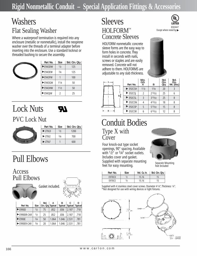
w w w . c a r l o n . c o m166
Rigid Nonmetallic Conduit – Special Application Fittings & Accessories
Flat Sealing Washer
Part No. Size Std. Ctn. Qty.
E943DW 1/2 125
E943EW 3/4 125
E943FW 1 100
E943GW 11/4 50
E943HW 11/2 50
E943JW 2 25
▲▲
▲▲
Part No. Size Std. Ctn. Qty.
LT9LD 1/2 1200
LT9LE 3/4 700
LT9LF 1 600
▲▲
▲▲
▲
PVC Lock Nut
HOLFORM nonmetallic concretesleeve forms are the easy way toform holes in concrete. Theyinstall in seconds with nails,screws or staples and are easilyremoved. Concrete will notadhere to them. HOLFORMS areadjustable to any slab thickness.
Where a waterproof termination is required into anyenclosure (metallic or nonmetallic), install the neoprenewasher over the threads of a terminal adapter beforeinserting into the enclosure. Use a standard locknut orthreaded bushing to secure the assembly.
Std. A B C DPart No. Size Ctn. Qty. Typical Typical Typical Typical
E990D 1/2 75 .852 .836 2.187 .718
E990DR-CAR 1/2 25 .852 .836 2.187 .718
E990E 3/4 50 1.064 1.046 2.531 .781
E990ER-CAR 3/4 20 1.064 1.046 2.531 .781
▲▲
▲▲
Gasket included.
HOLFORM™
Concrete Sleeves
Min. Std. Std.O.D. Ctn. Ctn.
Part No. A B Qty. Wt. (lbs.)
E92CSH 11/2 13/4 20 3
E92CSJ 2 213/32 25 6
E92CSL 3 313/32 25 8
E92CSN 4 413/32 18 8
E92CSP 5 513/32 15 8
E92CSR 6 613/32 12 8
▲▲
▲▲
▲▲
Access Pull Elbows
Pull Elbows
SleevesWashers
Lock Nuts
E32447Except where noted by
▲
Conduit Bodies
Part No. Size Vol. Cu. In. Std. Ctn. Qty.E970CD 1/2 15.16 15E970CE 3/4 15.16 15
Type X withCoverFour knock-out type socket openings, 90° spacing. Availablewith 1/2” or 3/4” socket outlets.Includes cover and gasket.Supplied with separate mountingfeet for easy mounting.
Separate Mounting Feet Included
Supplied with 4 stainless steel cover screws. Diameter 41/8", Thickness 1/4".*Not designed for use with wiring devices or light fixtures.
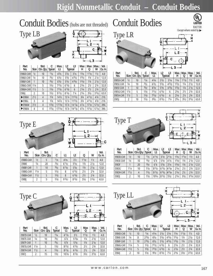
w w w . c a r l o n . c o m 167
Rigid Nonmetallic Conduit – Conduit Bodies
Part Std. C Max. L2 L3 Max Max Max. Vol.No. Size Ctn. Qty. Typical L1 Typical H Q W Cu. In.
E986D-CAR 1/2 10 11/16 45/16 37/32 31/16 15/16 111/32 11/2 4.0E986E-CAR 3/4 10 29/32 69/32 59/32 425/32 125/32 13/4 21/32 12.0E986F-CAR 1 10 29/32 69/32 59/32 425/32 125/32 13/4 21/32 12.0E986G-CAR 11/4 5 13/32 731/32 613/32 6 25/16 21/2 23/4 32.0E986H-CAR 11/2 5 13/32 731/32 613/32 6 25/16 21/2 23/4 32.0E986J 2 10 15/32 931/32 813/32 71/4 29/16 35/32 315/32 63.0
E986K 21/2 4 15/8 147/8 131/4 1131/32 33/4 411/32 4 5/8 210.E986L 3 4 15/8 147/8 131/4 1131/32 33/4 411/32 4 5/8 210.E986M 31/2 4 125/32 1723/32 157/8 1417/64 47/16 511/32 521/32 390.E986N 4 4 125/32 1723/32 157/8 1417/64 47/16 511/32 521/32 390.
Conduit Bodies (hubs are not threaded)
Type LB
Part Std. Vol.No. Size Ctn. Qty. C L1 L2 Q W Cu. In.
E988D-CAR 1/2 5 11/16 45/16 31/2 111/32 11/2 4.0E988E 3/4 20 29/32 611/32 59/32 13/4 21/32 12.0E988F-CAR 1 10 29/32 611/32 59/32 13/4 21/32 12.0E988G-CAR 11/4 5 13/32 8 613/32 21/2 23/4 32.0E988H-CAR 11/2 5 13/32 8 613/32 21/2 23/4 32.0E988J 2 5 15/32 915/32 813/32 35/32 315/32 63.0
Type E
Part Std. C Max. L2 Max Max. Vol.No. Size Ctn. Qty. Typical L1 Typical Q W Cu. In.
E987D-CAR 1/2 10 11/16 411/16 31/2 111/32 11/2 4.0E987E-CAR 3/4 10 29/32 67/8 532/64 13/4 21/32 12.0E987F-CAR 1 10 29/32 67/8 59/32 13/4 21/32 12.0E987G-CAR 11/4 5 13/32 821/32 613/32 21/2 23/4 32.0E987H-CAR 11/2 4 13/32 821/32 613/32 21/2 23/4 32.0E987J 2 15 15/32 105/16 813/32 35/32 315/32 63.0
Type C
Conduit Bodies
Part Std. C Max. L2 L3 Max. Max. Max. Vol.No. Size Ctn. Qty. Typical L1 Typical H Q W Cu. In.
E985D-CAR 1/2 10 11/16 45/16 37/32 31/16 15/16 111/32 11/2 4.0E985E-CAR 3/4 10 29/32 69/32 59/32 425/32 125/32 13/4 21/32 12.0E985F-CAR 1 10 29/32 69/32 59/32 425/32 125/32 13/4 21/32 12.0E985G-CAR 11/4 5 13/32 731/32 613/32 6 25/16 21/2 23/4 32.0E985H-CAR 11/2 5 13/32 731/32 613/32 6 25/16 21/2 23/4 32.0E985J 2 10 15/32 99/32 813/32 71/4 29/16 35/32 315/32 63.0
Type LR
Part Std. C Max. L2 L3 Max Max Max. Vol.No. Size Ctn.Qty. Typical L1 Typical H Q W Cu. In.
E983D-CAR 1/2 10 11/16 411/16 37/32 211/32 15/16 111/32 11/2 4.0E983E-CAR 3/4 10 29/32 67/8 59/32 47/16 125/32 13/4 21/32 12.0E983F 1 20 29/32 67/8 59/32 37/16 125/32 13/4 21/32 12.0E983G 11/4 10 13/32 821/32 613/32 421/64 25/16 21/2 23/4 32.0E983H-CAR 11/2 4 13/32 821/32 613/32 421/64 25/16 21/2 23/4 32.0E983J 2 10 15/32 105/16 813/32 55/32 29/16 35/32 315/16 63.0
Type T
Part Std. C Max. L2 L3 Max Max Max. Vol.No. Size Ctn. Qty. Typical L1 Typical H Q W Cu. In.
E984D-CAR 1/2 10 11/16 45/16 37/32 31/16 15/16 111/32 11/2 4.0E984E-CAR 3/4 8 229/32 69/32 59/32 425/32 125/32 13/4 21/32 12.0E984F-CAR 1 10 229/32 69/32 59/32 425/32 125/32 13/4 21/32 12.0E984G-CAR 11/4 5 13/32 731/32 613/32 6 25/16 21/2 23/4 32.0E984H-CAR 11/2 5 13/32 731/32 613/32 6 25/16 21/2 23/4 32.0E984J 2 10 15/32 99/32 813/32 71/4 29/16 35/32 315/32 63.0
Type LL▲
▲▲
▲
E42728Except where noted by
▲
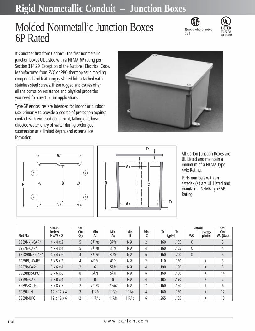
w w w . c a r l o n . c o m168
Rigid Nonmetallic Conduit – Junction Boxes
Molded Nonmetallic Junction Boxes6P RatedIt’s another first from Carlon® - the first nonmetallic junction boxes UL Listed with a NEMA 6P rating perSection 314.29, Exception of the National Electrical Code.Manufactured from PVC or PPO thermoplastic moldingcompound and featuring gasketed lids attached withstainless steel screws, these rugged enclosures offer all the corrosion resistance and physical properties you need for direct burial applications.
Type 6P enclosures are intended for indoor or outdooruse, primarily to provide a degree of protection againstcontact with enclosed equipment, falling dirt, hose-directed water, entry of water during prolonged submersion at a limited depth, and external ice formation.
All Carlon Junction Boxes areUL Listed and maintain a minimum of a NEMA Type4/4x Rating.
Parts numbers with an asterisk (*) are UL Listed andmaintain a NEMA Type 6PRating.
E42728E110981
Except where notedby †
Size in Std. Material Std.Inches Ctn. Min Min. Min. Min. Ta Tc Thermo- Ctn.
Part No. H x W x D Qty. AT AB B C PVC plastic Wt. (Lbs.)
E989NNJ-CAR* 4 x 4 x 2 5 311/16 35/8 N/A 2 .160 .155 X 3
E987N-CAR* 4 x 4 x 4 5 311/16 31/2 N/A 4 .160 .155 X 4
†E989NNR-CAR* 4 x 4 x 6 4 311/16 33/8 N/A 6 .160 .200 X 5
E989PPJ-CAR* 5 x 5 x 2 4 411/16 41/2 N/A 2 .110 .150 X 3
E987R-CAR* 6 x 6 x 4 2 6 55/8 N/A 4 .190 .190 X 3
E989RRR-UPC* 6 x 6 x 6 8 55/8 53/8 N/A 6 .160 .150 X 14
E989N-CAR 8 x 8 x 4 1 8 8 N/A 4 .185 .190 X 2
E989SSX-UPC 8 x 8 x 7 2 721/32 75/16 N/A 7 .160 .150 X 6
E989UUN 12 x 12 x 4 3 115/8 111/2 111/8 4 .160 .150 X 12
E989R-UPC 12 x 12 x 6 2 1115/16 117/8 117/16 6 .265 .185 X 10
Typical
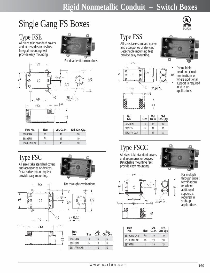
w w w . c a r l o n . c o m 169
Rigid Nonmetallic Conduit – Switch Boxes
Type FSE
Single Gang FS Boxes
Part No. Size Vol. Cu. In. Std. Ctn. Qty.E980DFN 1/2 19 10
E980EFN 3/4 19 10
E980FFN-CAR 1 19 10
All sizes take standard coversand accessories or devices.Integral mounting feet provide easy mounting.
For dead-end terminations.
Type FSCAll sizes take standard coversand accessories or devices.Detachable mounting feet provide easy mounting.
For through terminations.
Part Vol. Std.No. Size Cu. In. Ctn. Qty.
E981DFN 1/2 19 15
E981EFN 3/4 19 15
E981FFN-CAR 1 19 10
E42728
Type FSSAll sizes take standard coversand accessories or devices.Detachable mounting feet provide easy mounting.
For multiple dead-end circuitterminations or where additional support is requiredin stub-up applications.
Type FSCCAll sizes take standard coversand accessories or devices.Detachable mounting feet provide easy mounting.
For multiplethrough circuitterminations or where additional support isrequired in stub-up applications.
Part Vol. Std.No. Size Cu. In. Ctn. Qty.
E979DFN-CAR 1/2 19 10
E979EFN-CAR 3/4 19 10
E979FFN 1 19 15
Part Vol. Std.No. Size Cu. In. Ctn. Qty.
E982DFN 1/2 19 10
E982EFN 3/4 19 10
E982FFN-CAR 1 19 8
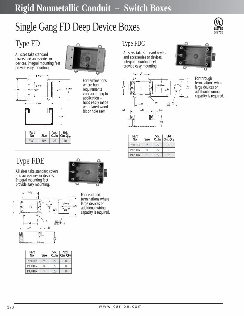
w w w . c a r l o n . c o m170
Rigid Nonmetallic Conduit – Switch Boxes
Single Gang FD Deep Device BoxesType FDAll sizes take standard covers and accessories ordevices. Integral mounting feetprovide easy mounting.
For terminationswhere hubrequirementsvary according toapplication –hubs easily madewith flared woodbit or hole saw.
Part Vol. Std.No. Size Cu. In. Ctn.Qty.
E9801 N/A 25 10
For dead-end terminations wherelarge devices or additional wiringcapacity is required.
Type FDEAll sizes take standard coversand accessories or devices.Integral mounting feet provide easy mounting.
Part Vol. Std.No. Size Cu. In. Ctn. Qty.
E9801DN 1/2 25 10
E9801EN 3/4 25 10
E9801FN 1 25 10
Part Vol. Std.No. Size Cu. In. Ctn. Qty.
E9811DN 1/2 25 10
E9811EN 3/4 25 10
E9811FN 1 25 10
Type FDCAll sizes take standard coversand accessories or devices.Integral mounting feet provide easy mounting.
For through terminations wherelarge devices or additional wiring capacity is required.
E42728
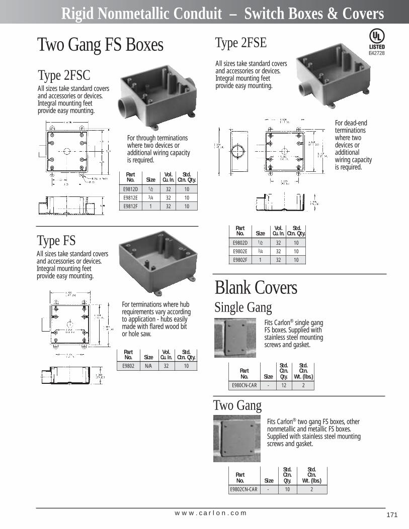
w w w . c a r l o n . c o m 171
Rigid Nonmetallic Conduit – Switch Boxes & Covers
Two Gang FS Boxes
Type 2FSC
Part Vol. Std.No. Size Cu. In. Ctn. Qty.
E9812D 1/2 32 10
E9812E 3/4 32 10
E9812F 1 32 10
All sizes take standard coversand accessories or devices.Integral mounting feet provide easy mounting.
For through terminationswhere two devices or additional wiring capacity is required.
Type FS
Part Vol. Std.No. Size Cu. In. Ctn. Qty.
E9802 N/A 32 10
All sizes take standard coversand accessories or devices.Integral mounting feet provide easy mounting.
For terminations where hubrequirements vary accordingto application - hubs easilymade with flared wood bit or hole saw.
Type 2FSE
Part Vol. Std.No. Size Cu. In. Ctn. Qty.
E9802D 1/2 32 10
E9802E 3/4 32 10
E9802F 1 32 10
All sizes take standard coversand accessories or devices.Integral mounting feet provide easy mounting.
For dead-end terminationswhere twodevices or additional wiring capacity is required.
Blank Covers
Std. Std.Part Ctn. Ctn.No. Size Qty. Wt. (lbs.)
E980CN-CAR - 12 2
Fits Carlon® single gang FS boxes. Supplied with stainless steel mounting screws and gasket.
Single Gang
Std. Std.Part Ctn. Ctn.No. Size Qty. Wt. (lbs.)
E9802CN-CAR - 10 2
Fits Carlon® two gang FS boxes, othernonmetallic and metallic FS boxes.Supplied with stainless steel mountingscrews and gasket.
Two Gang
E42728
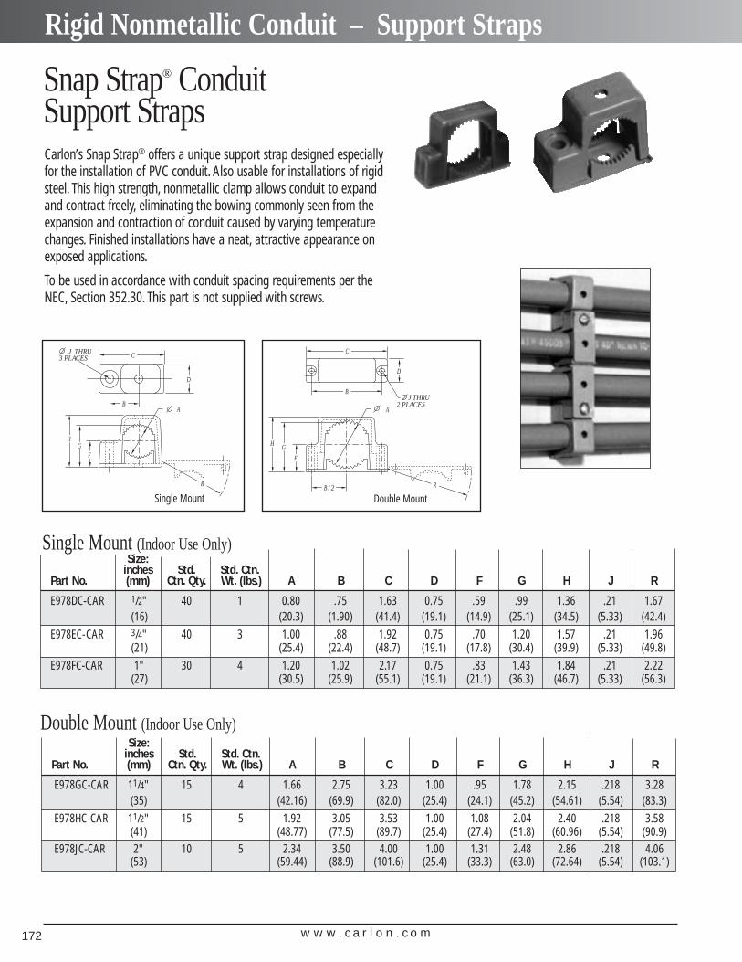
w w w . c a r l o n . c o m172
Rigid Nonmetallic Conduit – Support Straps
H G
F
A
D
C
B
B / 2 R
2 PLACESJ THRU
Size:inches Std. Std. Ctn.
Part No. (mm) Ctn. Qty. Wt. (lbs.) A B C D F G H J R
E978DC-CAR 1/2" 40 1 0.80 .75 1.63 0.75 .59 .99 1.36 .21 1.67(16) (20.3) (1.90) (41.4) (19.1) (14.9) (25.1) (34.5) (5.33) (42.4)
E978EC-CAR 3/4" 40 3 1.00 .88 1.92 0.75 .70 1.20 1.57 .21 1.96(21) (25.4) (22.4) (48.7) (19.1) (17.8) (30.4) (39.9) (5.33) (49.8)
E978FC-CAR 1" 30 4 1.20 1.02 2.17 0.75 .83 1.43 1.84 .21 2.22(27) (30.5) (25.9) (55.1) (19.1) (21.1) (36.3) (46.7) (5.33) (56.3)
Single Mount (Indoor Use Only)
Single Mount Double Mount
FG
H
A
R
D
B
CJ THRU3 PLACES
Snap Strap® Conduit Support StrapsCarlon’s Snap Strap® offers a unique support strap designed especiallyfor the installation of PVC conduit. Also usable for installations of rigidsteel. This high strength, nonmetallic clamp allows conduit to expand and contract freely, eliminating the bowing commonly seen from theexpansion and contraction of conduit caused by varying temperaturechanges. Finished installations have a neat, attractive appearance onexposed applications.
To be used in accordance with conduit spacing requirements per theNEC, Section 352.30. This part is not supplied with screws.
Size:inches Std. Std. Ctn.
Part No. (mm) Ctn. Qty. Wt. (lbs.) A B C D F G H J R
E978GC-CAR 11/4" 15 4 1.66 2.75 3.23 1.00 .95 1.78 2.15 .218 3.28(35) (42.16) (69.9) (82.0) (25.4) (24.1) (45.2) (54.61) (5.54) (83.3)
E978HC-CAR 11/2" 15 5 1.92 3.05 3.53 1.00 1.08 2.04 2.40 .218 3.58(41) (48.77) (77.5) (89.7) (25.4) (27.4) (51.8) (60.96) (5.54) (90.9)
E978JC-CAR 2" 10 5 2.34 3.50 4.00 1.00 1.31 2.48 2.86 .218 4.06(53) (59.44) (88.9) (101.6) (25.4) (33.3) (63.0) (72.64) (5.54) (103.1)
Double Mount (Indoor Use Only)
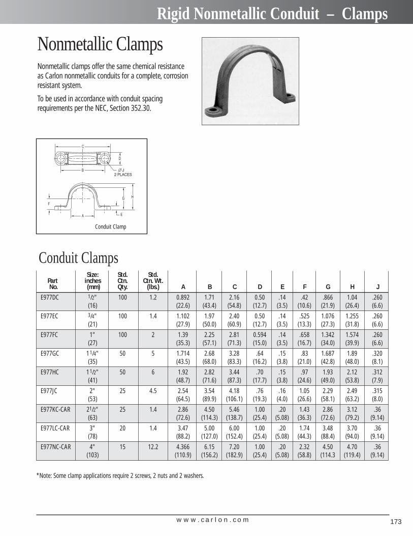
w w w . c a r l o n . c o m 173
Rigid Nonmetallic Conduit – Clamps
Conduit Clamps
Conduit Clamp
Size: Std. Std.Part inches Ctn. Ctn. Wt.No. (mm) Qty. (lbs.) A B C D E F G H J
E977DC 1/2" 100 1.2 0.892 1.71 2.16 0.50 .14 .42 .866 1.04 .260(16) (22.6) (43.4) (54.8) (12.7) (3.5) (10.6) (21.9) (26.4) (6.6)
E977EC 3/4" 100 1.4 1.102 1.97 2.40 0.50 .14 .525 1.076 1.255 .260(21) (27.9) (50.0) (60.9) (12.7) (3.5) (13.3) (27.3) (31.8) (6.6)
E977FC 1" 100 2 1.39 2.25 2.81 0.594 .14 .658 1.342 1.574 .260(27) (35.3) (57.1) (71.3) (15.0) (3.5) (16.7) (34.0) (39.9) (6.6)
E977GC 11/4" 50 5 1.714 2.68 3.28 .64 .15 .83 1.687 1.89 .320(35) (43.5) (68.0) (83.3) (16.2) (3.8) (21.0) (42.8) (48.0) (8.1)
E977HC 11/2" 50 6 1.92 2.82 3.44 .70 .15 .97 1.93 2.12 .312(41) (48.7) (71.6) (87.3) (17.7) (3.8) (24.6) (49.0) (53.8) (7.9)
E977JC 2" 25 4.5 2.54 3.54 4.18 .76 .16 1.05 2.29 2.49 .315(53) (64.5) (89.9) (106.1) (19.3) (4.0) (26.6) (58.1) (63.2) (8.0)
E977KC-CAR 21/2" 25 1.4 2.86 4.50 5.46 1.00 .20 1.43 2.86 3.12 .36(63) (72.6) (114.3) (138.7) (25.4) (5.08) (36.3) (72.6) (79.2) (9.14)
E977LC-CAR 3" 20 1.4 3.47 5.00 6.00 1.00 .20 1.74 3.48 3.70 .36(78) (88.2) (127.0) (152.4) (25.4) (5.08) (44.3) (88.4) (94.0) (9.14)
E977NC-CAR 4" 15 12.2 4.366 6.15 7.20 1.00 .20 2.32 4.50 4.70 .36(103) (110.9) (156.2) (182.9) (25.4) (5.08) (58.8) (114.3 (119.4) (9.14)
Nonmetallic ClampsNonmetallic clamps offer the same chemical resistance as Carlon nonmetallic conduits for a complete, corrosionresistant system.
To be used in accordance with conduit spacing requirements per the NEC, Section 352.30.
*Note: Some clamp applications require 2 screws, 2 nuts and 2 washers.
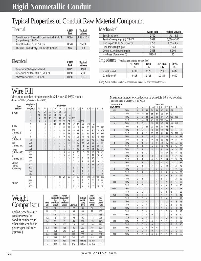
w w w . c a r l o n . c o m174
Rigid Nonmetallic Conduit
Typical Properties of Conduit Raw Material Compound
Wire Fill
ConductorType Size Trade Size
Letters AWG, MCM 1/2 3/4 1 11/4 11/2 2 21/2 3 31/2 4 41/4 5 6 814 13 24 39 69 94 15412 10 18 29 51 79 114 16410 6 11 18 32 44 73 194 1608 3 5 9 19 22 36 51 71 106 1366 1 4 6 11 15 26 37 57 76 98 125 1544 1 2 4 7 9 16 22 35 47 60 75 94 137 2363 1 1 3 6 8 13 19 29 39 51 64 90 116 2012 1 1 3 5 7 11 16 25 33 43 54 67 97 1691 1 1 3 5 9 12 18 25 32 49 59 72 125
1/0 1 1 3 4 7 10 15 21 27 33 42 61 1052/0 1 1 2 3 6 8 13 17 22 28 35 51 883/0 1 1 1 3 5 7 11 14 18 23 29 42 734/0 1 1 1 2 4 6 9 12 15 19 24 35 61250 1 1 1 3 4 7 10 12 16 20 28 49300 1 1 1 3 4 6 8 11 13 17 24 42350 1 1 1 2 3 5 7 9 12 15 21 37400 1 1 1 3 5 6 8 10 13 19 33500 1 1 1 2 4 5 7 9 11 16 27600 1 1 1 1 3 4 5 7 9 13 22700 1 1 1 3 4 5 6 8 11 19750 1 1 1 2 3 4 6 7 11 19
6 1 3 5 9 13 21 30 47 63 81 102 128 185 320600 1 1 1 1 3 4 5 7 9 13 22700 1 1 1 3 4 5 6 7 11 19750 1 1 1 2 3 4 6 7 10 18
Thermal ASTM Typical Test Values
Co-efficient of Thermal Expansion-inch/inch/°F D696 3.38 x 10⁻⁵
(properties @ 73.4°F)Heat Distortion °F at 264 psi D648 160°FThermal Conductivity BTU (hr.) (ft.) (°F/in.) N/A 1.3
Electrical ASTM Typical Test Values
Dielectrical Strength volts/mil D149 1100Dielectric Constant 60 CPS @ 30°C D150 4.00Power Factor 60 CPS @ 30°C D150 1.93
MechanicalASTM Test Typical Values
Specific Gravity D792 1.43 - 1.6Tensile Strength (psi) @ 73.4°F D638 5,000-6,500Izod Impact ft lbs./in. of notch D256 0.65 - 1.5Flexural Strength (psi) D790 12,500Compressive Strength (psi) D695 9,000Hardness (Durometer D) D2240 85
Impedance (Volts lost per ampere per 100 feet)3� 90% 80% 1� 90% 80%
P.F. P.F. P.F. P.F.
Steel Conduit .0118 .0123 .0136 .0142
Schedule 40® .0105 .0106 .0121 .0122
Using 250 KCmil Cu. conductor. comparable values for other conductor sizes.
THWN
THHN
FEP (14 thru 2)
FEPB (14 thru 8)
PFA (14 thru 4/0)
PFAH (14 thru 4/0)
Z (14 thru 4/0)
XHHW(4 thru500MCM)
XHHW
Maximum number of conductors in Schedule 80 PVC conduit (Based on Table 1, Chapter 9 of the NEC)Conductor Size Trade SizeAWG, MCM 1/2 3/4 1 11/4 11/2 2 21/2 3 4 5
# 14 THW 4 8 13 24 34 57 82 128THHN 10 19 33 58 81 135 194 0
12 THW 3 6 11 20 28 47 67 105 183THHN 8 14 24 43 60 100 144 0
10 THW 3 5 9 16 22 37 54 85 148THHN 5 9 15 27 38 64 92 143
8 THW 1 2 4 8 11 19 28 44 77 121THHN 1 4 7 13 18 31 45 70 123 195
6 THW 1 1 3 6 8 14 20 32 56 88THHN 1 3 5 9 13 22 32 50 88 140
4 THW 0 1 2 4 6 10 15 24 42 66THHN 1 1 3 6 8 13 20 31 54 86
3 THW 0 1 1 4 5 9 13 20 36 57THHN 1 1 2 5 7 11 17 26 46 73
2 THW 0 1 1 3 4 8 11 17 31 49THHN 1 1 1 4 5 9 14 22 38 61
1 THW 0 1 1 1 3 5 8 13 22 35THHN 0 1 1 3 4 7 10 16 28 45
0 THW 0 0 1 1 2 4 7 11 19 30THHN 0 1 1 2 3 6 8 13 24 38
00 THW 0 0 1 1 1 4 6 9 16 26THHN 0 1 1 1 3 5 7 11 20 32
000 THW 0 0 1 1 1 3 5 8 14 22THHN 0 0 1 1 2 4 6 9 16 26
0000 THW 0 0 1 1 1 3 4 6 11 18THHN 0 0 1 1 1 3 5 8 14 22
250 THW 0 0 0 1 1 1 3 5 9 14THHN 0 0 0 1 1 2 4 6 11 18
300 ThW 0 0 0 1 1 1 3 4 8 13THHN 0 0 0 1 1 1 3 5 9 15
350 THW 0 0 0 1 1 1 2 4 7 11THHN 0 0 0 1 1 1 3 4 8 13
400 THW 0 0 0 0 1 1 1 3 6 10THHN 0 0 0 1 1 1 2 4 7 12
500 THW 0 0 0 0 1 1 1 3 5 8THHN 0 0 0 0 1 1 1 3 6 10
600 THW 0 0 0 0 0 1 1 1 4 7THHN 0 0 0 0 1 1 1 3 5 8
700 THW 0 0 0 0 0 1 1 1 3 6
Carlon Carlon Inter-Schedule 40® Schedule 80® Electrical mediate Rigid
Rigid Rigid Metallic Metal MetalNom. Nonmetallic Nonmetallic Tubing Conduit ConduitSize Conduit Conduit Aluminum (EMT) (IMC) (RMC)1/2 18 22 27 30 57 793/4 23 29 36 46 78 1051 35 43 53 66 112 153
11/4 48 60 70 96 114 20111/2 57 72 86 112 176 2462 76 100 116 142 230 334
21/2 125 153 183 230 393 5273 164 212 239 270 483 690
31/2 198 288 350 561 8314 234 310 340 400 625 9825 317 431 465 Not Made Not Made 13446 412 592 612 Not Made Not Made 1770
WeightComparisonCarlon Schedule 40®
rigid nonmetallic conduit compared toother rigid conduit inpounds per 100 feet(approx.)
Maximum number of conductors in Schedule 40 PVC conduit (Based on Table 1, Chapter 9 of the NEC)
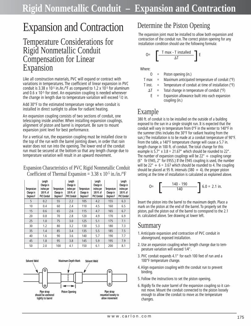
w w w . c a r l o n . c o m 175
Rigid Nonmetallic Conduit – Expansion and Contraction
Temperature Considerations forRigid Nonmetallic ConduitCompensation for LinearExpansion
Expansion and Contraction
Like all construction materials, PVC will expand or contract with variations in temperatures. The coefficient of linear expansion in PVCconduit is 3.38 x 10⁻⁵ in./in./°F as compared to 1.2 x 10⁻⁵ for aluminumand 0.6 x 10⁻⁵ for steel. An expansion coupling is needed wheneverthe change in length due to temperature variation will exceed 1/2 in.
Add 30°F to the estimated temperature range when conduit isinstalled in direct sunlight to allow for radiant heating.
An expansion coupling consists of two sections of conduit, one telescoping inside another. When installing expansion couplings,alignment of piston and barrel is important. Be sure to mount expansion joint level for best performance.
For a vertical run, the expansion coupling must be installed close tothe top of the run with the barrel jointing down, in order that rainwater does not run into the opening. The lower end of the conduit run must be secured at the bottom so that any length change due totemperature variation will result in an upward movement.
Expansion Characteristics of PVC Rigid Nonmetallic ConduitCoefficient of Thermal Expansion = 3.38 x 10⁻⁵ in./in./°F
Length Length Length Length Change in Change in Change in Change in
Temperature inches per Temperature inches per Temperature inches per Temperature inches perChange in 100 Ft. of Change in 100 Ft. of Change in 100 Ft. of Change in 100 Ft. ofDegrees F PVC Conduit Degrees F PVC Conduit Degrees F PVC Conduit Degrees F PVC Conduit
5 0.2 55 2.2 105 4.2 155 6.3
10 0.4 60 2.4 110 4.5 160 6.5
15 0.6 65 2.6 115 4.7 165 6.7
20 0.8 70 2.8 120 4.9 170 6.9
25 1.0 75 3.0 125 5.1 175 7.1
30 1.2 80 3.2 130 5.3 180 7.3
35 1.4 85 3.4 135 5.5 185 7.5
40 1.6 90 3.6 140 5.7 190 7.7
45 1.8 95 3.8 145 5.9 195 7.9
50 2.0 100 4.1 150 6.1 200 8.1
The expansion joint must be installed to allow both expansion andcontraction of the conduit run. The correct piston opening for anyinstallation condition should use the following formula:
Determine the Piston Opening
O= ET max - T installed�T[ ]
Where:O = Piston opening (in.)
T max = Maximum anticipated temperature of conduit (°F)T inst. = Temperature of conduit at time of installation (°F)
�T = Total change in temperature of conduit (°F)E = Expansion allowance built into each expansion
coupling (in.)
380 ft. of conduit is to be installed on the outside of a buildingexposed to the sun in a single straight run. It is expected that theconduit will vary in temperature from 0°F in the winter to 140°F inthe summer (this includes the 30°F for radiant heating from thesun.) The installation is to be made at a conduit temperature of 90°F.From the table, a 140°F temperature change will cause a 5.7 in.length change in 100 ft. of conduit. The total change for this example is 5.7" x 3.8 = 21.67" which should be rounded to 22".The number of expansion couplings will be 22"� coupling range(6" fir E945, 2" for E955.) If the E945 coupling is used, the numberwill be 22"� 6 = 3.67 which should be rounded to 4. The couplingshould be placed at 95 ft. intervals (380 � 4). the proper piston setting at the time of installation is calculated as explained above.
Example
O= 6.0 = 2.1 in.140 - 190140[ ]
Insert the piston into the barrel to the maximum depth. Place amark on the piston at the end of the barrel. To properly set thepiston, pull the piston out of the barrel to correspond to the 2.1in. calculated above. See drawing at lower left.
Summary1. Anticipate expansion and contraction of PVC conduit in
aboveground, exposed installation.
2. Use an expansion coupling when length change due to tem-perature variation will exceed 1/4".
3. PVC conduit expands 4.1" for each 100 feet of run and a100°F temperature change.
4. Align expansion coupling with the conduit run to preventbinding.
5. Follow the instructions to set the piston opening.
6. Rigidly fix the outer barrel of the expansion coupling so it can-not move. Mount the conduit connected to the piston looselyenough to allow the conduit to move as the temperaturechanges.
Solvent Weld Solvent WeldMaximum Depth Mark
Piston OpeningPipe strap should be anchored
tightly to barrel
Pipe strap mounted loosely to
allow movement
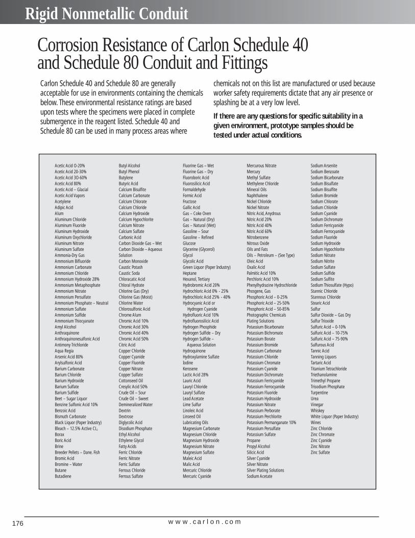
w w w . c a r l o n . c o m176
Rigid Nonmetallic Conduit
Corrosion Resistance of Carlon Schedule 40 and Schedule 80 Conduit and FittingsCarlon Schedule 40 and Schedule 80 are generally acceptable for use in environments containing the chemicalsbelow. These environmental resistance ratings are basedupon tests where the specimens were placed in completesubmergence in the reagent listed. Schedule 40 andSchedule 80 can be used in many process areas where
chemicals not on this list are manufactured or used becauseworker safety requirements dictate that any air presence orsplashing be at a very low level.
If there are any questions for specific suitability in agiven environment, prototype samples should be tested under actual conditions.
Acetic Acid O-20%Acetic Acid 20-30%Acetic Acid 3O-60%Acetic Acid 80%Acetic Acid – GlacialAcetic Acid VaporsAcetyleneAdipic AcidAlumAluminum ChlorideAluminum FluorideAluminum HydroxideAluminum OxychlorideAluminum NitrateAluminum SulfateAmmonia-Dry GasAmmonium BifluorideAmmonium CarbonateAmmonium ChlorideAmmonium Hydroxide 28%Ammonium MetaphosphateAmmonium NitrateAmmonium PersulfateAmmonium Phosphate – NeutralAmmonium SulfateAmmonium SulfideAmmonium ThiocyanateAmyl AlcoholAnthraquinoneAnthraquinonesulfonic AcidAntimony TrichlorideAqua RegiaArsenic Acid 80%Arylsulfonic AcidBarium CarbonateBarium ChlorideBarium HydroxideBarium SulfateBarium SulfideBeet – Sugar LiquorBenzine Sulfonic Acid 10%Benzoic AcidBismuth CarbonateBlack Liquor (Paper Industry)Bleach – 12.5% Active CL2
BoraxBoric AcidBrineBreeder Pellets – Dane. FishBromic AcidBromine – WaterButaneButadiene
Butyl AlcoholButyl PhenolButyleneButyric AcidCalcium BisulfiteCalcium CarbonateCalcium ChlorateCalcium ChlorideCalcium HydroxideCalcium HypochloriteCalcium NitrateCalcium SulfateCarbonic AcidCarbon Dioxide Gas – WetCarbon Dioxide – AqueousSolutionCarbon MonoxideCaustic PotashCaustic SodaChloracatic AcidChloral HydrateChlorine Gas (Dry)Chlorine Gas (Moist)Chlorine WaterChlorosulfonic AcidChrome AlumChromic Acid 10%Chromic Acid 30%Chromic Acid 40%Chromic Acid 50%Citric AcidCopper ChlorideCopper CyanideCopper FluorideCopper NitrateCopper SulfateCottonseed OilCresylic Acid 50%Crude Oil – SourCrude Oil – SweetDemineralized WaterDextrinDextroseDiglycolic AcidDisodium PhosphateEthyl AlcoholEthylene GlycolFatty AcidsFerric ChlorideFerric NitrateFerric SulfateFerrous ChlorideFerrous Sulfate
Fluorine Gas – WetFluorine Gas – DryFluoroboric AcidFluorosilicic AcidFormaldehydeFormic AcidFructoseGallic AcidGas – Coke OvenGas – Natural (Dry)Gas – Natural (Wet)Gasoline – SourGasoline – RefinedGlucoseGlycerine (Glycerol)GlycolGlycolic AcidGreen Liquor (Paper Industry)HeptaneHexanol, TertiaryHydrobromic Acid 20%Hydrochloric Acid 0% - 25%Hydrochloric Acid 25% - 40%Hydrocyanic Acid or
Hydrogen CyanideHydrofluoric Acid 10%Hydrofluorosilicic AcidHydrogen PhosphideHydrogen Sulfide – DryHydrogen Sulfide –
Aqueous SolutionHydroquinoneHydroxylamine SulfateIodineKeroseneLactic Acid 28%Lauric AcidLauryl ChlorideLauryl SulfateLead AcetateLime SulfurLinoleic AcidLinseed OilLubricating OilsMagnesium CarbonateMagnesium ChlorideMagnesium HydroxideMagnesium NitrateMagnesium SulfateMaleic AcidMalic AcidMercuric ChlorideMercuric Cyanide
Mercurous NitrateMercuryMethyl SulfateMethylene ChlorideMineral OilsNaphthaleneNickel ChlorideNickel NitrateNitric Acid, AnydrousNitric Acid 20%Nitric Acid 40%Nitric Acid 60%NitrobenzeneNitrous OxideOils and FatsOils – Petroleum – (See Type)Oleic AcidOxalic AcidPalmitic Acid 10%Perchloric Acid 10%Phenylhydrazine HydrochloridePhosgene, GasPhosphoric Acid – 0-25%Phosphoric Acid – 25-50%Phosphoric Acid – 50-85%Photographic ChemicalsPlating SolutionsPotassium BicarbonatePotassium BichromatePotassium BoratePotassium BromidePotassium CarbonatePotassium ChloridePotassium ChromatePotassium CyanidePotassium DichromatePotassium FerricyanidePotassium FerrocyanidePotassium FluoridePotassium HydroxidePotassium NitratePotassium PerboratePotassium PerchloritePotassium Permanganate 10%Potassium PersulfatePotassium SulfatePropanePropyl AlcoholSilicic AcidSilver CyanideSilver NitrateSilver Plating SolutionsSodium Acetate
Sodium ArseniteSodium BenzoateSodium BicarbonateSodium BisulfateSodium BisulfiteSodium BromideSodium ChlorateSodium ChlorideSodium CyanideSodium DichromateSodium FerricyanideSodium FerrocyanideSodium FluorideSodium HydroxideSodium HypochloriteSodium NitrateSodium NitriteSodium SulfateSodium SulfideSodium SulfiteSodium Thiosulfate (Hypo)Stannic ChlorideStannous ChlorideStearic AcidSulfurSulfur Dioxide – Gas DrySulfur TrioxideSulfuric Acid – 0-10%Sulfuric Acid – 10-75%Sulfuric Acid – 75-90%Sulfurous AcidTannic AcidTanning LiquorsTartaric AcidTitanium TetrachlorideTriethanolamineTrimethyl PropaneTrisodium PhosphateTurpentineUreaVinegarWhiskeyWhite Liquor (Paper Industry)WinesZinc ChlorideZinc ChromateZinc CyanideZinc NitrateZinc Sulfate
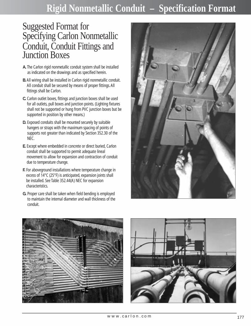
w w w . c a r l o n . c o m 177
Rigid Nonmetallic Conduit – Specification Format
A. The Carlon rigid nonmetallic conduit system shall be installed as indicated on the drawings and as specified herein.
B. All wiring shall be installed in Carlon rigid nonmetallic conduit.All conduit shall be secured by means of proper fittings. All fittings shall be Carlon.
C. Carlon outlet boxes, fittings and junction boxes shall be usedfor all outlets, pull boxes and junction points. (Lighting fixturesshall not be supported or hung from PVC junction boxes but besupported in position by other means.)
D. Exposed conduits shall be mounted securely by suitable hangers or straps with the maximum spacing of points of supports not greater than indicated by Section 352.30 of theNEC.
E. Except where embedded in concrete or direct buried, Carlonconduit shall be supported to permit adequate lineal movement to allow for expansion and contraction of conduitdue to temperature change.
F. For aboveground installations where temperature change inexcess of 14°C (25°F) is anticipated, expansion joints shall be installed. See Table 352.44(A) NEC for expansion characteristics.
G. Proper care shall be taken when field bending is employed to maintain the internal diameter and wall thickness of theconduit.
Suggested Format forSpecifying Carlon NonmetallicConduit, Conduit Fittings andJunction Boxes
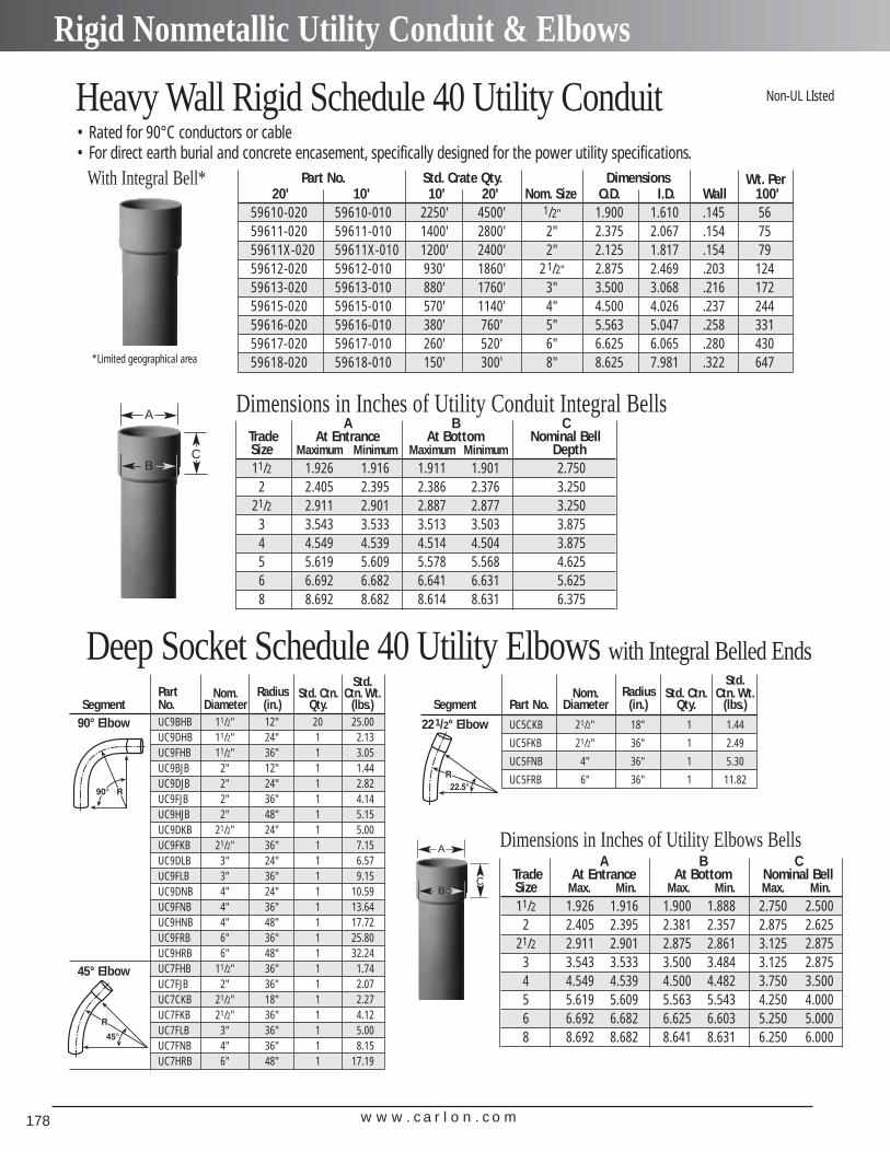
w w w . c a r l o n . c o m178
Rigid Nonmetallic Utility Conduit & Elbows
Part No. Std. Crate Qty. Dimensions Wt. Per20' 10' 10' 20' Nom. Size O.D. I.D. Wall 100'
59610-020 59610-010 2250' 4500' 1/2" 1.900 1.610 .145 5659611-020 59611-010 1400' 2800' 2" 2.375 2.067 .154 7559611X-020 59611X-010 1200' 2400' 2" 2.125 1.817 .154 7959612-020 59612-010 930' 1860' 21/2" 2.875 2.469 .203 12459613-020 59613-010 880' 1760' 3" 3.500 3.068 .216 17259615-020 59615-010 570' 1140' 4" 4.500 4.026 .237 24459616-020 59616-010 380' 760' 5" 5.563 5.047 .258 33159617-020 59617-010 260' 520' 6" 6.625 6.065 .280 43059618-020 59618-010 150' 300' 8" 8.625 7.981 .322 647
Heavy Wall Rigid Schedule 40 Utility Conduit• Rated for 90°C conductors or cable• For direct earth burial and concrete encasement, specifically designed for the power utility specifications.
With Integral Bell*
*Limited geographical area
A B CTrade At Entrance At Bottom Nominal BellSize Maximum Minimum Maximum Minimum Depth11/2 1.926 1.916 1.911 1.901 2.750
2 2.405 2.395 2.386 2.376 3.25021/2 2.911 2.901 2.887 2.877 3.250
3 3.543 3.533 3.513 3.503 3.8754 4.549 4.539 4.514 4.504 3.8755 5.619 5.609 5.578 5.568 4.6256 6.692 6.682 6.641 6.631 5.6258 8.692 8.682 8.614 8.631 6.375
Non-UL LIsted
Deep Socket Schedule 40 Utility Elbows with Integral Belled Ends
Dimensions in Inches of Utility Conduit Integral Bells
Std.Part Nom. Radius Std. Ctn. Ctn. Wt.
Segment No. Diameter (in.) Qty. (lbs.)90° Elbow UC9BHB 11/2" 12" 20 25.00
UC9DHB 11/2" 24" 1 2.13UC9FHB 11/2" 36" 1 3.05UC9BJB 2" 12" 1 1.44UC9DJB 2" 24" 1 2.82UC9FJB 2" 36" 1 4.14UC9HJB 2" 48" 1 5.15UC9DKB 21/2" 24" 1 5.00UC9FKB 21/2" 36" 1 7.15UC9DLB 3" 24" 1 6.57UC9FLB 3" 36" 1 9.15UC9DNB 4" 24" 1 10.59UC9FNB 4" 36" 1 13.64UC9HNB 4" 48" 1 17.72UC9FRB 6" 36" 1 25.80UC9HRB 6" 48" 1 32.24
45° Elbow UC7FHB 11/2" 36" 1 1.74UC7FJB 2" 36" 1 2.07UC7CKB 21/2" 18" 1 2.27UC7FKB 21/2" 36" 1 4.12UC7FLB 3" 36" 1 5.00UC7FNB 4" 36" 1 8.15UC7HRB 6" 48" 1 17.19
Std.Nom. Radius Std. Ctn. Ctn. Wt.
Segment Part No. Diameter (in.) Qty. (lbs.)
221/2° Elbow UC5CKB 21/2" 18" 1 1.44
UC5FKB 21/2" 36" 1 2.49
UC5FNB 4" 36" 1 5.30
UC5FRB 6" 36" 1 11.82
A
BC
A B CTrade At Entrance At Bottom Nominal BellSize Max. Min. Max. Min. Max. Min.11/2 1.926 1.916 1.900 1.888 2.750 2.500
2 2.405 2.395 2.381 2.357 2.875 2.62521/2 2.911 2.901 2.875 2.861 3.125 2.875
3 3.543 3.533 3.500 3.484 3.125 2.8754 4.549 4.539 4.500 4.482 3.750 3.5005 5.619 5.609 5.563 5.543 4.250 4.0006 6.692 6.682 6.625 6.603 5.250 5.0008 8.692 8.682 8.641 8.631 6.250 6.000
Dimensions in Inches of Utility Elbows BellsA
BC
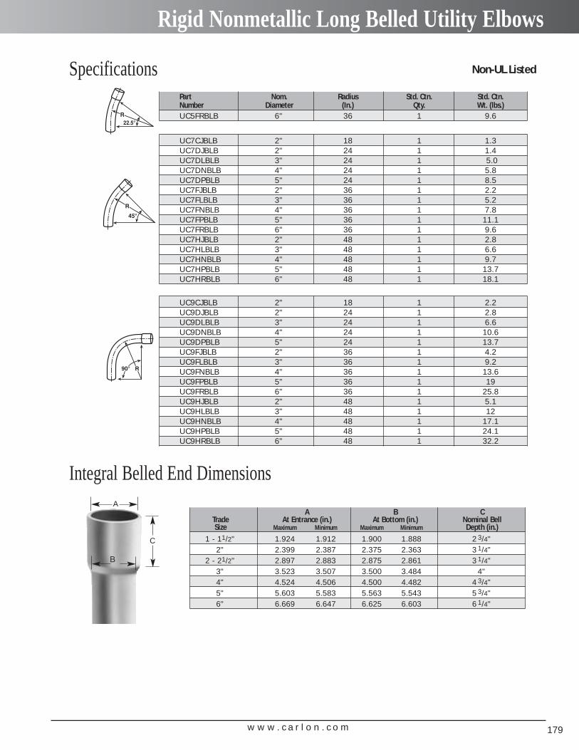
w w w . c a r l o n . c o m 179
Rigid Nonmetallic Long Belled Utility Elbows
SpecificationsPart Nom. Radius Std. Ctn. Std. Ctn.Number Diameter (In.) Qty. Wt. (lbs.)UC5FRBLB 6" 36 1 9.6
UC7CJBLB 2" 18 1 1.3UC7DJBLB 2" 24 1 1.4UC7DLBLB 3" 24 1 5.0 UC7DNBLB 4" 24 1 5.8UC7DPBLB 5" 24 1 8.5UC7FJBLB 2" 36 1 2.2UC7FLBLB 3" 36 1 5.2UC7FNBLB 4" 36 1 7.8UC7FPBLB 5" 36 1 11.1UC7FRBLB 6" 36 1 9.6UC7HJBLB 2" 48 1 2.8UC7HLBLB 3" 48 1 6.6UC7HNBLB 4" 48 1 9.7UC7HPBLB 5" 48 1 13.7UC7HRBLB 6" 48 1 18.1
UC9CJBLB 2" 18 1 2.2UC9DJBLB 2" 24 1 2.8UC9DLBLB 3" 24 1 6.6UC9DNBLB 4" 24 1 10.6UC9DPBLB 5" 24 1 13.7UC9FJBLB 2" 36 1 4.2UC9FLBLB 3" 36 1 9.2UC9FNBLB 4" 36 1 13.6UC9FPBLB 5" 36 1 19UC9FRBLB 6" 36 1 25.8UC9HJBLB 2" 48 1 5.1UC9HLBLB 3" 48 1 12UC9HNBLB 4" 48 1 17.1UC9HPBLB 5" 48 1 24.1UC9HRBLB 6" 48 1 32.2
A B CTrade At Entrance (in.) At Bottom (in.) Nominal BellSize Maximum Minimum Maximum Minimum Depth (in.)
1 - 11/2" 1.924 1.912 1.900 1.888 2 3/4"2" 2.399 2.387 2.375 2.363 3 1/4"
2 - 21/2" 2.897 2.883 2.875 2.861 3 1/4"3" 3.523 3.507 3.500 3.484 4"4" 4.524 4.506 4.500 4.482 4 3/4"5" 5.603 5.583 5.563 5.543 5 3/4"6" 6.669 6.647 6.625 6.603 6 1/4"
A
B
C
Non-UL Listed
Integral Belled End Dimensions
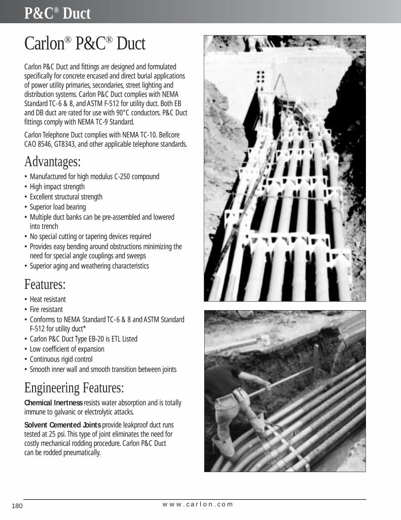
w w w . c a r l o n . c o m180
P&C® Duct
Carlon® P&C® DuctCarlon P&C Duct and fittings are designed and formulatedspecifically for concrete encased and direct burial applicationsof power utility primaries, secondaries, street lighting and distribution systems. Carlon P&C Duct complies with NEMAStandard TC-6 & 8, and ASTM F-512 for utility duct. Both EBand DB duct are rated for use with 90°C conductors. P&C Ductfittings comply with NEMA TC-9 Standard.
Carlon Telephone Duct complies with NEMA TC-10. BellcoreCAO 8546, GT8343, and other applicable telephone standards.
Advantages:• Manufactured for high modulus C-250 compound• High impact strength• Excellent structural strength• Superior load bearing• Multiple duct banks can be pre-assembled and lowered
into trench• No special cutting or tapering devices required• Provides easy bending around obstructions minimizing the
need for special angle couplings and sweeps• Superior aging and weathering characteristics
Features:• Heat resistant• Fire resistant• Conforms to NEMA Standard TC-6 & 8 and ASTM Standard
F-512 for utility duct*• Carlon P&C Duct Type EB-20 is ETL Listed• Low coefficient of expansion• Continuous rigid control• Smooth inner wall and smooth transition between joints
Engineering Features:Chemical Inertness resists water absorption and is totallyimmune to galvanic or electrolytic attacks.
Solvent Cemented Joints provide leakproof duct runs tested at 25 psi. This type of joint eliminates the need for costly mechanical rodding procedure. Carlon P&C Duct can be rodded pneumatically.
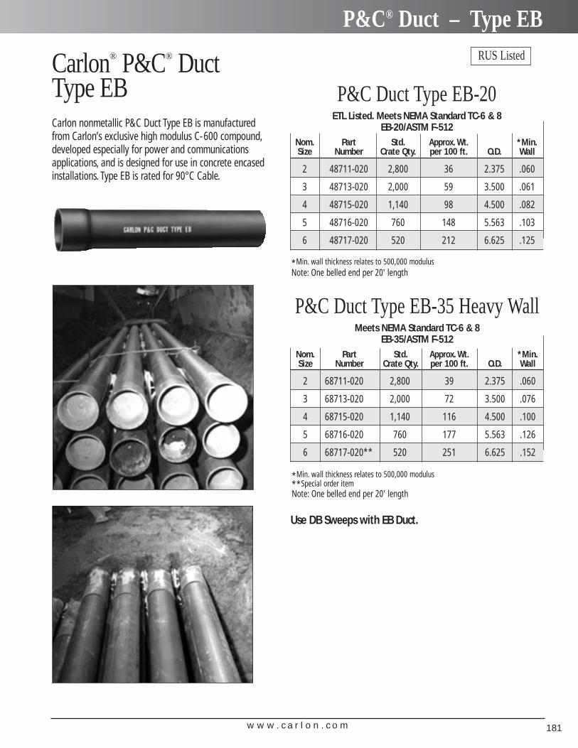
w w w . c a r l o n . c o m 181
P&C® Duct – Type EBRUS ListedCarlon® P&C® Duct
Type EBCarlon nonmetallic P&C Duct Type EB is manufacturedfrom Carlon’s exclusive high modulus C-600 compound,developed especially for power and communicationsapplications, and is designed for use in concrete encasedinstallations. Type EB is rated for 90°C Cable.
P&C Duct Type EB-20 ETL Listed. Meets NEMA Standard TC-6 & 8
EB-20/ASTM F-512Nom. Part Std. Approx. Wt. *Min.Size Number Crate Qty. per 100 ft. O.D. Wall
2 48711-020 2,800 36 2.375 .060
3 48713-020 2,000 59 3.500 .061
4 48715-020 1,140 98 4.500 .082
5 48716-020 760 148 5.563 .103
6 48717-020 520 212 6.625 .125
P&C Duct Type EB-35 Heavy Wall Meets NEMA Standard TC-6 & 8
EB-35/ASTM F-512Nom. Part Std. Approx. Wt. *Min.Size Number Crate Qty. per 100 ft. O.D. Wall
2 68711-020 2,800 39 2.375 .060
3 68713-020 2,000 72 3.500 .076
4 68715-020 1,140 116 4.500 .100
5 68716-020 760 177 5.563 .126
6 68717-020** 520 251 6.625 .152
*Min. wall thickness relates to 500,000 modulus**Special order itemNote: One belled end per 20' length
*Min. wall thickness relates to 500,000 modulusNote: One belled end per 20' length
Use DB Sweeps with EB Duct.
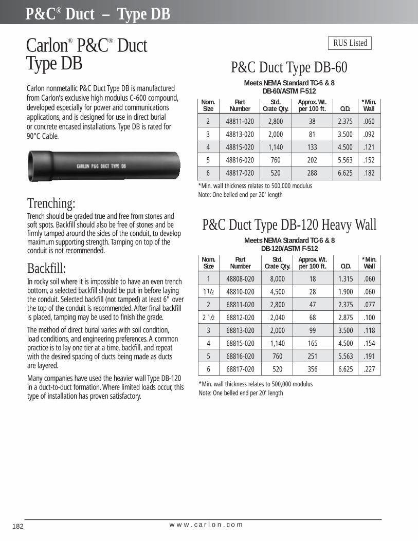
w w w . c a r l o n . c o m182
P&C® Duct – Type DB
Trenching:Trench should be graded true and free from stones andsoft spots. Backfill should also be free of stones and befirmly tamped around the sides of the conduit, to developmaximum supporting strength. Tamping on top of the conduit is not recommended.
Backfill:In rocky soil where it is impossible to have an even trench bottom, a selected backfill should be put in before layingthe conduit. Selected backfill (not tamped) at least 6" overthe top of the conduit is recommended. After final backfillis placed, tamping may be used to finish the grade.
The method of direct burial varies with soil condition,load conditions, and engineering preferences. A commonpractice is to lay one tier at a time, backfill, and repeatwith the desired spacing of ducts being made as ducts are layered.
Many companies have used the heavier wall Type DB-120in a duct-to-duct formation. Where limited loads occur, thistype of installation has proven satisfactory.
Carlon® P&C® Duct Type DBCarlon nonmetallic P&C Duct Type DB is manufacturedfrom Carlon’s exclusive high modulus C-600 compound,developed especially for power and communicationsapplications, and is designed for use in direct burial or concrete encased installations. Type DB is rated for90°C Cable.
RUS Listed
P&C Duct Type DB-60 Meets NEMA Standard TC-6 & 8
DB-60/ASTM F-512Nom. Part Std. Approx. Wt. *Min.Size Number Crate Qty. per 100 ft. O.D. Wall
2 48811-020 2,800 38 2.375 .060
3 48813-020 2,000 81 3.500 .092
4 48815-020 1,140 133 4.500 .121
5 48816-020 760 202 5.563 .152
6 48817-020 520 288 6.625 .182
P&C Duct Type DB-120 Heavy Wall Meets NEMA Standard TC-6 & 8
DB-120/ASTM F-512Nom. Part Std. Approx. Wt. *Min.Size Number Crate Qty. per 100 ft. O.D. Wall
1 48808-020 8,000 18 1.315 .060
11/2 48810-020 4,500 28 1.900 .060
2 68811-020 2,800 47 2.375 .077
2 1/2 68812-020 2,040 68 2.875 .100
3 68813-020 2,000 99 3.500 .118
4 68815-020 1,140 165 4.500 .154
5 68816-020 760 251 5.563 .191
6 68817-020 520 356 6.625 .227
*Min. wall thickness relates to 500,000 modulusNote: One belled end per 20' length
*Min. wall thickness relates to 500,000 modulusNote: One belled end per 20' length
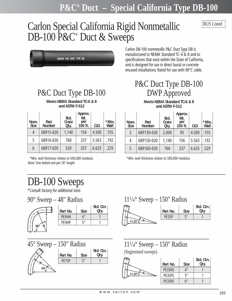
w w w . c a r l o n . c o m 183
P&C® Duct – Special California Type DB-100
Carlon Special California Rigid Nonmetallic DB-100 P&C® Duct & Sweeps
Carlon DB-100 nonmetallic P&C Duct Type DB is manufactured to NEMA Standard TC-6 & 8 and tospecifications that exist within the State of California,and is designed for use in direct burial or concreteencased installations. Rated for use with 90°C cable.
Std. Ctn.Part No. Size Qty.PE9HN 4" 1PE9HP 5" 1
90° Sweep – 48" Radius
Std. Ctn.Part No. Size Qty.
PE7SP 5" 1
Std. Ctn.Part No. Size Qty.
PE3SP 5" 1
45° Sweep – 150" Radius
111/4° Sweep – 150" Radius
Std. Ctn.Part No. Size Qty.PE3SNS 4" 1PE3SPS 5" 1PE3SRS 6" 1
111/4° Sweep – 150" Radius (Segmented sweeps)
P&C Duct Type DB-100 Meets NEMA Standard TC-6 & 8
and ASTM F-512
Approx.Std. Wt.
Nom. Part Crate per *Min.Size Number Qty. 100 ft. O.D. Wall
4 68915-020 1,140 154 4.500 .155
5 68916-020 760 237 5.563 .192
6 68917-020 520 337 6.625 .229
P&C Duct Type DB-100DWP Approved
Meets NEMA Standard TC-6 & 8 and ASTM F-512
Approx.Std. Wt.
Nom. Part Crate per *Min.Size Number Qty. 100 ft. O.D. Wall
3 68913D-020 2,000 95 4.500 .155
4 68915D-020 1,140 156 5.563 .192
5 68916D-020 760 237 6.625 .229
*Min. wall thickness relates to 500,000 modulusNote: One belled end per 20' length
*Min. wall thickness relates to 500,000 modulus
RUS Listed
DB-100 Sweeps*Consult factory for additional sizes
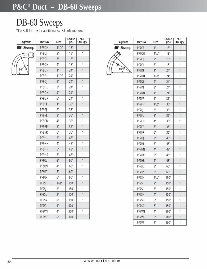
w w w . c a r l o n . c o m184
P&C® Duct – DB-60 Sweeps
DB-60 Sweeps*Consult factory for additional sizes/configurations
Radius Std.Segment Part No. Size (in.) Ctn. Qty.
90° Sweep PF9CH 11/2" 18" 1
PF9CJ 2" 18" 1
PF9CL 3" 18" 1
PF9CN 4" 18" 1
PF9DF 1" 24" 1
PF9DH 11/2" 24" 1
PF9DJ 2" 24" 1
PF9DL 3" 24" 1
PF9DN 4" 24" 1
PF9DP 5" 24" 1
PF9FF 1" 36" 1
PF9FJ 2" 36" 1
PF9FL 3" 36" 1
PF9FN 4" 36" 1
PF9FP 5" 36" 1
PF9FR 6" 36" 1
PF9HL 3" 48" 1
PF9HN 4" 48" 1
PF9HP 5" 48" 1
PF9HR 6" 48" 1
PF9IL 3" 60" 1
PF9IN 4" 60" 1
PF9IP 5" 60" 1
PF9IR 6" 60" 1
PF9SH 11/2" 150" 1
PF9SJ 2" 150" 1
PF9SL 3" 150" 1
PF9SR 6" 150" 1
PF9VL 3" 300" 1
PF9VN 4" 300" 1
PF9VP 5" 300" 1
Radius Std.Segment Part No. Size (in.) Ctn. Qty.
45° Sweep PF7CF 1" 18" 1
PF7CH 11/2" 18" 1
PF7CJ 2" 18" 1
PF7CL 3" 18" 1
PF7DF 1" 24" 1
PF7DH 11/2" 24" 1
PF7DJ 2" 24" 1
PF7DL 3" 24" 1
PF7DN 4" 24" 1
PF7FF 1" 36" 1
PF7FH 11/2" 36" 1
PF7FJ 2" 36" 1
PF7FL 3" 36" 1
PF7FN 4" 36" 1
PF7FP 5" 36" 1
PF7FR 6" 36" 1
PF7HJ 2" 48" 1
PF7HL 3" 48" 1
PF7HN 4" 48" 1
PF7HP 5" 48" 1
PF7HR 6" 48" 1
PF7IL 3" 60" 1
PF7IP 5" 60" 1
PF7SH 11/2" 150" 1
PF7SJ 2" 150" 1
PF7SL 3" 150" 1
PF7SN 4" 150" 1
PF7SP 5" 150" 1
PF7SR 6" 150" 1
PF7VN 4" 300" 1
PF7VP 5" 300" 1
PF7VR 6" 300" 1
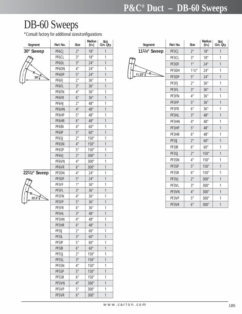
w w w . c a r l o n . c o m 185
P&C® Duct – DB-60 Sweeps
DB-60 Sweeps*Consult factory for additional sizes/configurations
Radius Std.Segment Part No. Size (in.) Ctn. Qty.
30° Sweep PF6CJ 2" 18" 1PF6CL 3" 18" 1PF6DL 3" 24" 1PF6DN 4" 24" 1PF6DP 5" 24" 1PF6FJ 2" 36" 1PF6FL 3" 36" 1PF6FN 4" 36" 1PF6FR 6" 36" 1PF6HJ 2" 48" 1PF6HN 4" 48" 1PF6HP 5" 48" 1PF6HR 6" 48" 1PF6IN 4" 60" 1PF6IP 5" 60" 1PF6SJ 2" 150" 1PF6SN 4" 150" 1PF6SP 5" 150" 1PF6VJ 2" 300" 1PF6VN 4" 300" 1PF6VR 6" 300" 1
221/2° Sweep PF5DN 4" 24" 1PF5DP 5" 24" 1PF5FF 1" 36" 1PF5FL 3" 36" 1PF5FN 4" 36" 1PF5FP 5" 36" 1PF5FR 6" 36" 1PF5HL 3" 48" 1PF5HN 4" 48" 1PF5HR 6" 48" 1PF5IJ 2" 60" 1PF5IL 3" 60" 1PF5IP 5" 60" 1PF5IR 6" 60" 1PF5SJ 2" 150" 1PF5SL 3" 150" 1PF5SN 4" 150" 1PF5SP 5" 150" 1PF5SR 6" 150" 1PF5VN 4" 300" 1PF5VP 5" 300" 1PF5VR 6" 300" 1
Radius Std.Segment Part No. Size (in.) Ctn. Qty.
111/4° Sweep PF3CJ 2" 18" 1
PF3CL 3" 18" 1
PF3DF 1" 24" 1
PF3DH 11/2" 24" 1
PF3DP 5" 24" 1
PF3FJ 2" 36" 1
PF3FL 3" 36" 1
PF3FN 4" 36" 1
PF3FP 5" 36" 1
PF3FR 6" 36" 1
PF3HL 3" 48" 1
PF3HN 4" 48" 1
PF3HP 5" 48" 1
PF3HR 6" 48" 1
PF3IJ 2" 60" 1
PF3IR 6" 60" 1
PF3SJ 2" 150" 1
PF3SN 4" 150" 1
PF3SP 5" 150" 1
PF3SR 6" 150" 1
PF3VJ 2" 300" 1
PF3VL 3" 300" 1
PF3VN 4" 300" 1
PF3VP 5" 300" 1
PF3VR 6" 300" 1
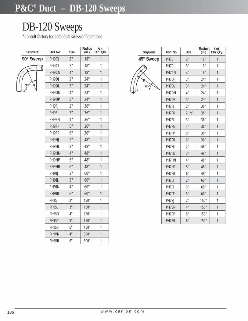
w w w . c a r l o n . c o m186
P&C® Duct – DB-120 Sweeps
DB-120 Sweeps*Consult factory for additional sizes/configurations
Radius Std.Segment Part No. Size (in.) Ctn. Qty.
90° Sweep PH9CJ 2" 18" 1
PH9CL 3" 18" 1
PH9CN 4" 18" 1
PH9DJ 2" 24" 1
PH9DL 3" 24" 1
PH9DN 4" 24" 1
PH9DP 5" 24" 1
PH9FJ 2" 36" 1
PH9FL 3" 36" 1
PH9FN 4" 36" 1
PH9FP 5" 36" 1
PH9FR 6" 36" 1
PH9HJ 2" 48" 1
PH9HL 3" 48" 1
PH9HN 4" 48" 1
PH9HP 5" 48" 1
PH9HR 6" 48" 1
PH9IJ 2" 60" 1
PH9IL 3" 60" 1
PH9IN 4" 60" 1
PH9IR 6" 60" 1
PH9SJ 2" 150" 1
PH9SL 3" 150" 1
PH9SN 4" 150" 1
PH9SP 5" 150" 1
PH9SR 6" 150" 1
PH9VN 4" 300" 1
PH9VR 6" 300" 1
Radius Std.Segment Part No. Size (in.) Ctn. Qty.
45° Sweep PH7CJ 2" 18" 1
PH7CL 3" 18" 1
PH7CN 4" 18" 1
PH7DJ 2" 24" 1
PH7DL 3" 24" 1
PH7DN 4" 24" 1
PH7DP 5" 24" 1
PH7FJ 2" 36" 1
PH7FK 2 1/2" 36" 1
PH7FL 3" 36" 1
PH7FN 4" 36" 1
PH7FP 5" 36" 1
PH7FR 6" 36" 1
PH7HJ 2" 48" 1
PH7HL 3" 48" 1
PH7HN 4" 48" 1
PH7HP 5" 48" 1
PH7HR 6" 48" 1
PH7IJ 2" 60" 1
PH7IL 3" 60" 1
PH7IP 5" 60" 1
PH7SJ 2" 150" 1
PH7SN 4" 150" 1
PH7SP 5" 150" 1
PH7SR 6" 150" 1
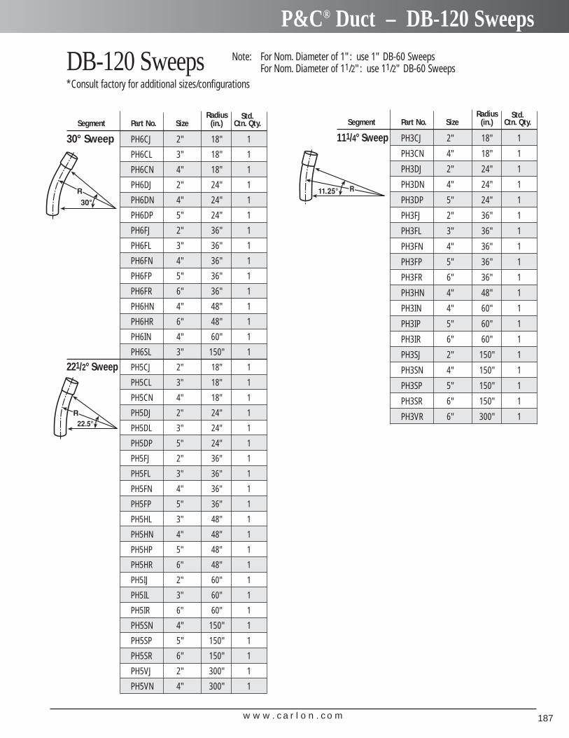
w w w . c a r l o n . c o m 187
P&C® Duct – DB-120 Sweeps
Radius Std.Segment Part No. Size (in.) Ctn. Qty.
30° Sweep PH6CJ 2" 18" 1
PH6CL 3" 18" 1
PH6CN 4" 18" 1
PH6DJ 2" 24" 1
PH6DN 4" 24" 1
PH6DP 5" 24" 1
PH6FJ 2" 36" 1
PH6FL 3" 36" 1
PH6FN 4" 36" 1
PH6FP 5" 36" 1
PH6FR 6" 36" 1
PH6HN 4" 48" 1
PH6HR 6" 48" 1
PH6IN 4" 60" 1
PH6SL 3" 150" 1
221/2° Sweep PH5CJ 2" 18" 1
PH5CL 3" 18" 1
PH5CN 4" 18" 1
PH5DJ 2" 24" 1
PH5DL 3" 24" 1
PH5DP 5" 24" 1
PH5FJ 2" 36" 1
PH5FL 3" 36" 1
PH5FN 4" 36" 1
PH5FP 5" 36" 1
PH5HL 3" 48" 1
PH5HN 4" 48" 1
PH5HP 5" 48" 1
PH5HR 6" 48" 1
PH5IJ 2" 60" 1
PH5IL 3" 60" 1
PH5IR 6" 60" 1
PH5SN 4" 150" 1
PH5SP 5" 150" 1
PH5SR 6" 150" 1
PH5VJ 2" 300" 1
PH5VN 4" 300" 1
DB-120 Sweeps*Consult factory for additional sizes/configurations
Note: For Nom. Diameter of 1": use 1" DB-60 SweepsFor Nom. Diameter of 11/2": use 11/2" DB-60 Sweeps
Radius Std.Segment Part No. Size (in.) Ctn. Qty.
111/4° Sweep PH3CJ 2" 18" 1
PH3CN 4" 18" 1
PH3DJ 2" 24" 1
PH3DN 4" 24" 1
PH3DP 5" 24" 1
PH3FJ 2" 36" 1
PH3FL 3" 36" 1
PH3FN 4" 36" 1
PH3FP 5" 36" 1
PH3FR 6" 36" 1
PH3HN 4" 48" 1
PH3IN 4" 60" 1
PH3IP 5" 60" 1
PH3IR 6" 60" 1
PH3SJ 2" 150" 1
PH3SN 4" 150" 1
PH3SP 5" 150" 1
PH3SR 6" 150" 1
PH3VR 6" 300" 1
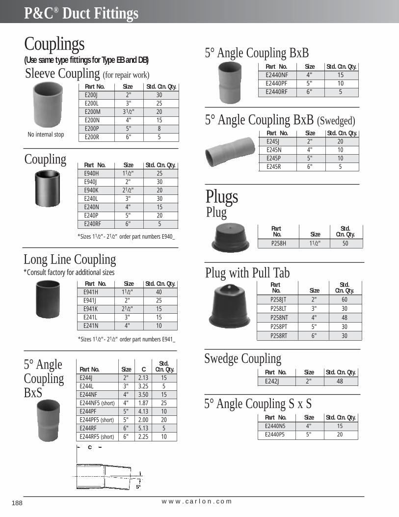
w w w . c a r l o n . c o m188
P&C® Duct Fittings
Part No. Size Std. Ctn. Qty.E940H 11/2" 25E940J 2" 30E940K 21/2" 20E240L 3" 30E240N 4" 15E240P 5" 20E240RF 6" 5
Part No. Size Std. Ctn. Qty.E941H 11/2" 40E941J 2" 25E941K 21/2" 15E241L 3" 15E241N 4" 10
Long Line Coupling*Consult factory for additional sizes
Part No. Size Std. Ctn. Qty.E200J 2" 30E200L 3" 25E200M 31/2" 20E200N 4" 15E200P 5" 8E200R 6" 5
Couplings (Use same type fittings for Type EB and DB)
Part No. Size Std. Ctn. Qty.E2440NF 4" 15E2440PF 5" 10E2440RF 6" 5
5° Angle Coupling BxB
Std.Part No. Size C Ctn. Qty.E244J 2" 2.13 15E244L 3" 3.25 5E244NF 4" 3.50 15E244NF5 (short) 4" 1.87 25E244PF 5" 4.13 10E244PF5 (short) 5" 2.00 20E244RF 6" 5.13 5E244RF5 (short) 6" 2.25 10
5° Angle CouplingBxS
Part Std.No. Size Ctn. Qty.
P258H 11/2" 50
Plug
Part Std.No. Size Ctn. Qty.
P258JT 2" 60P258LT 3" 30P258NT 4" 48P258PT 5" 30P258RT 6" 30
Plug with Pull Tab
Part No. Size Std. Ctn. Qty.E245J 2" 20E245N 4" 10E245P 5" 10E245R 6" 5
5° Angle Coupling BxB (Swedged)
Plugs
Coupling
Sleeve Coupling (for repair work)
No internal stop
Part No. Size Std. Ctn. Qty.E242J 2" 48
Swedge Coupling
Part No. Size Std. Ctn. Qty.E2440N5 4" 15E2440P5 5" 20
5° Angle Coupling S x S
*Sizes 11/2"- 21/2" order part numbers E940_
*Sizes 11/2"- 21/2" order part numbers E941_
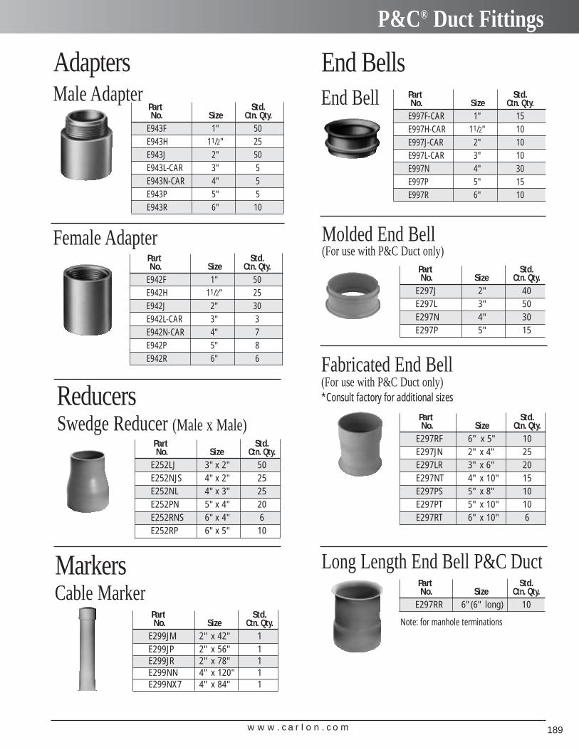
w w w . c a r l o n . c o m 189
P&C® Duct Fittings
Part Std.No. Size Ctn. Qty.
E943F 1" 50E943H 11/2" 25E943J 2" 50E943L-CAR 3" 5E943N-CAR 4" 5E943P 5" 5E943R 6" 10
Male Adapter
Part Std.No. Size Ctn. Qty.
E942F 1" 50E942H 11/2" 25E942J 2" 30E942L-CAR 3" 3E942N-CAR 4" 7E942P 5" 8E942R 6" 6
Female Adapter
Part Std.No. Size Ctn. Qty.
E997F-CAR 1" 15E997H-CAR 11/2" 10E997J-CAR 2" 10E997L-CAR 3" 10E997N 4" 30E997P 5" 15E997R 6" 10
End Bell
Part Std.No. Size Ctn. Qty.
E297J 2" 40E297L 3" 50E297N 4" 30E297P 5" 15
Molded End Bell (For use with P&C Duct only)
Part Std.No. Size Ctn. Qty.
E297RF 6" x 5" 10E297JN 2" x 4" 25E297LR 3" x 6" 20E297NT 4" x 10" 15E297PS 5" x 8" 10E297PT 5" x 10" 10E297RT 6" x 10" 6
Fabricated End Bell (For use with P&C Duct only)*Consult factory for additional sizes
Part Std.No. Size Ctn. Qty.
E252LJ 3"x 2" 50E252NJS 4"x 2" 25E252NL 4"x 3" 25E252PN 5"x 4" 20E252RNS 6"x 4" 6E252RP 6"x 5" 10
Swedge Reducer (Male x Male)
Part Std.No. Size Ctn. Qty.
E297RR 6"(6" long) 10
Long Length End Bell P&C Duct
Part Std.No. Size Ctn. Qty.
E299JM 2" x 42" 1E299JP 2" x 56" 1E299JR 2" x 78" 1E299NN 4" x 120" 1E299NX7 4" x 84" 1
Cable Marker
Adapters
Reducers
End Bells
Markers
Note: for manhole terminations
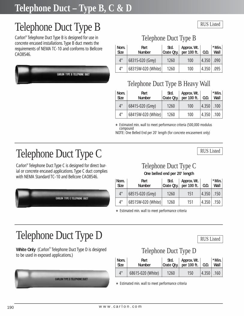
w w w . c a r l o n . c o m190
Telephone Duct – Type B, C & D
Telephone Duct Type BCarlon® Telephone Duct Type B is designed for use in concrete encased installations. Type B duct meets therequirements of NEMA TC-10 and conforms to BellcoreCAO8546.
Telephone Duct Type BNom. Part Std. Approx. Wt. *Min.Size Number Crate Qty. per 100 ft. O.D. Wall
4" 68315-020 (Grey) 1260 100 4.350 .090
4" 68315W-020 (White) 1260 100 4.350 .095
RUS Listed
Telephone Duct Type DNom. Part Std. Approx. Wt. *Min.Size Number Crate Qty. per 100 ft. O.D. Wall
4" 68615-020 (White) 1260 150 4.350 .160
Telephone Duct Type B Heavy WallNom. Part Std. Approx. Wt. *Min.Size Number Crate Qty. per 100 ft. O.D. Wall
4" 68415-020 (Grey) 1260 100 4.350 .100
4" 68415W-020 (White) 1260 100 4.350 .100
* Estimated min. wall to meet performance criteria (500,000 modulus compound
NOTE: One Belled End per 20' length (for concrete encasement only)
Telephone Duct Type CCarlon® Telephone Duct Type C is designed for direct bur-ial or concrete encased applications. Type C duct complieswith NEMA Standard TC-10 and Bellcore CAO8546.
RUS Listed
Telephone Duct Type COne belled end per 20' length
Nom. Part Std. Approx. Wt. *Min.Size Number Crate Qty. per 100 ft. O.D. Wall
4" 68515-020 (Grey) 1260 151 4.350 .150
4" 68515W-020 (White) 1260 151 4.350 .150
* Estimated min. wall to meet performance criteria
Telephone Duct Type DWhite Only (Carlon® Telephone Duct Type D is designedto be used in exposed applications.)
RUS Listed
* Estimated min. wall to meet performance criteria
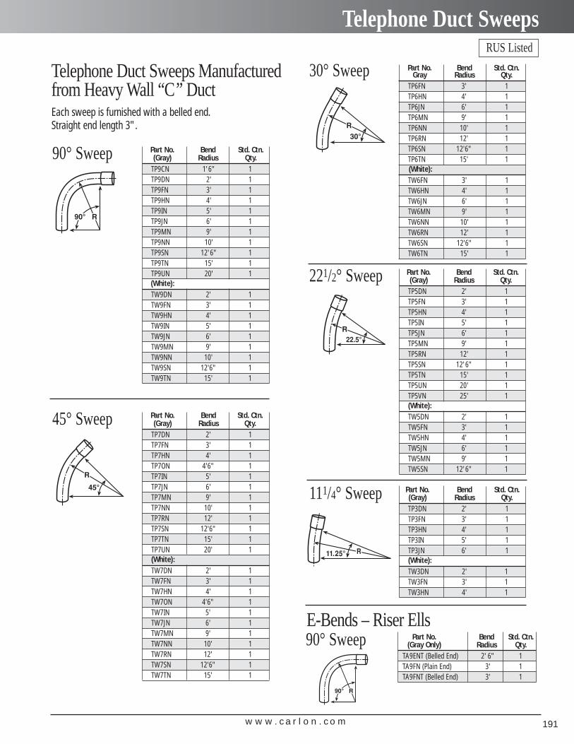
w w w . c a r l o n . c o m 191
Telephone Duct Sweeps
Telephone Duct Sweeps Manufacturedfrom Heavy Wall “C” DuctEach sweep is furnished with a belled end.Straight end length 3".
E-Bends – Riser Ells
Part No. Bend Std. Ctn.(Gray) Radius Qty.
TP9CN 1'6" 1TP9DN 2' 1TP9FN 3' 1TP9HN 4' 1TP9IN 5' 1TP9JN 6' 1TP9MN 9' 1TP9NN 10' 1TP9SN 12'6" 1TP9TN 15' 1TP9UN 20' 1(White):TW9DN 2' 1TW9FN 3' 1TW9HN 4' 1TW9IN 5' 1TW9JN 6' 1TW9MN 9' 1TW9NN 10' 1TW9SN 12'6" 1TW9TN 15' 1
90° Sweep
Part No. Bend Std. Ctn.(Gray) Radius Qty.TP5DN 2' 1TP5FN 3' 1TP5HN 4' 1TP5IN 5' 1TP5JN 6' 1TP5MN 9' 1TP5RN 12' 1TP5SN 12'6" 1TP5TN 15' 1TP5UN 20' 1TP5VN 25' 1(White):TW5DN 2' 1TW5FN 3' 1TW5HN 4' 1TW5JN 6' 1TW5MN 9' 1TW5SN 12'6" 1
221/2° Sweep
Part No. Bend Std. Ctn.Gray Radius Qty.
TP6FN 3' 1TP6HN 4' 1TP6JN 6' 1TP6MN 9' 1TP6NN 10' 1TP6RN 12' 1TP6SN 12'6" 1TP6TN 15' 1(White):TW6FN 3' 1TW6HN 4' 1TW6JN 6' 1TW6MN 9' 1TW6NN 10' 1TW6RN 12' 1TW6SN 12'6" 1TW6TN 15' 1
30° Sweep
Part No. Bend Std. Ctn.(Gray) Radius Qty.TP3DN 2' 1TP3FN 3' 1TP3HN 4' 1TP3IN 5' 1TP3JN 6' 1(White):TW3DN 2' 1TW3FN 3' 1TW3HN 4' 1
111/4° Sweep
Part No. Bend Std. Ctn.(Gray Only) Radius Qty.
TA9ENT (Belled End) 2' 6" 1TA9FN (Plain End) 3' 1TA9FNT (Belled End) 3' 1
90° Sweep
Part No. Bend Std. Ctn.(Gray) Radius Qty.
TP7DN 2' 1TP7FN 3' 1TP7HN 4' 1TP7ON 4'6" 1TP7IN 5' 1TP7JN 6' 1TP7MN 9' 1TP7NN 10' 1TP7RN 12' 1TP7SN 12'6" 1TP7TN 15' 1TP7UN 20' 1(White):TW7DN 2' 1TW7FN 3' 1TW7HN 4' 1TW7ON 4'6" 1TW7IN 5' 1TW7JN 6' 1TW7MN 9' 1TW7NN 10' 1TW7RN 12' 1TW7SN 12'6" 1TW7TN 15' 1
45° Sweep
RUS Listed
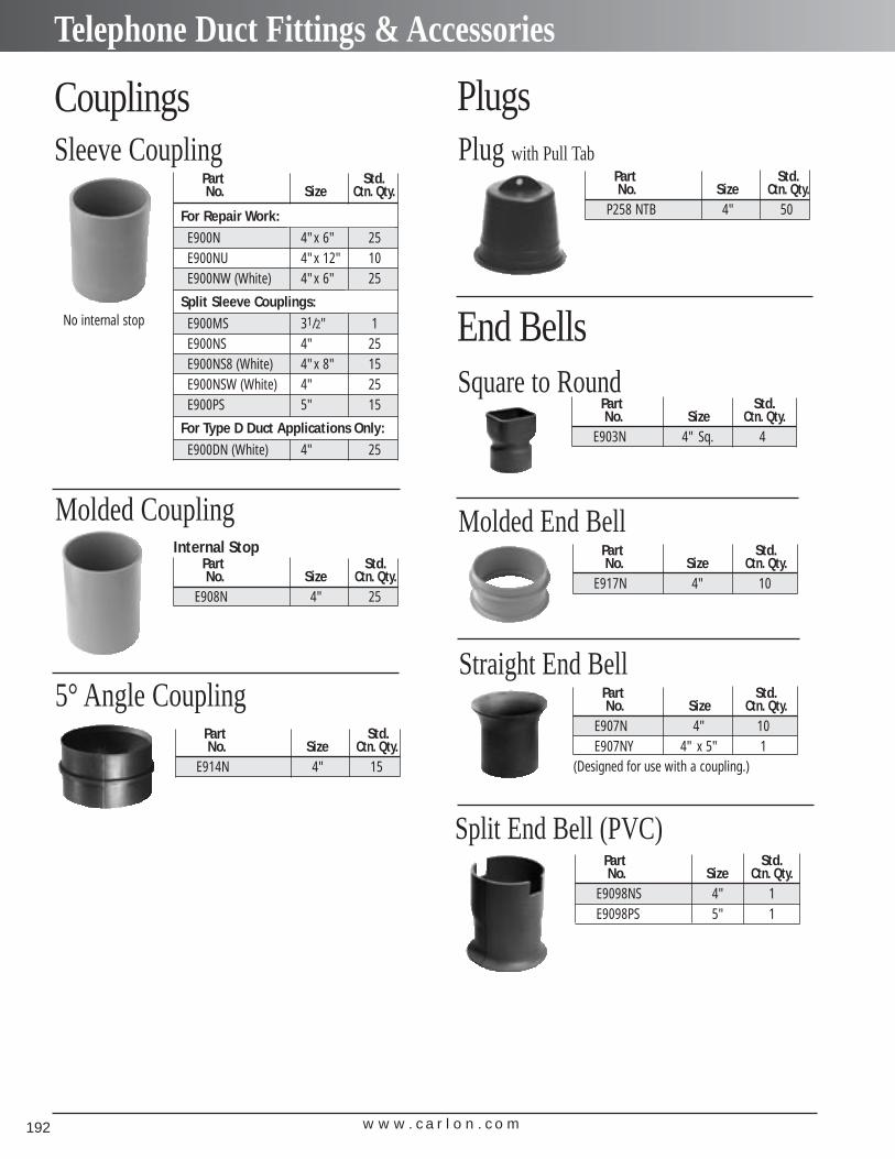
w w w . c a r l o n . c o m192
Telephone Duct Fittings & Accessories
Internal StopPart Std.No. Size Ctn. Qty.
E908N 4" 25
Molded Coupling
Part Std.No. Size Ctn. Qty.
E914N 4" 15
5° Angle Coupling
Part Std.No. Size Ctn. Qty.
For Repair Work:E900N 4"x 6" 25E900NU 4"x 12" 10E900NW (White) 4"x 6" 25
Split Sleeve Couplings:E900MS 31/2" 1E900NS 4" 25E900NS8 (White) 4"x 8" 15E900NSW (White) 4" 25E900PS 5" 15
For Type D Duct Applications Only:E900DN (White) 4" 25
Part Std.No. Size Ctn. Qty.
P258 NTB 4" 50
Plug with Pull Tab
Part Std.No. Size Ctn. Qty.
E903N 4" Sq. 4
Square to Round
Part Std.No. Size Ctn. Qty.
E917N 4" 10
Molded End Bell
Part Std.No. Size Ctn. Qty.
E907N 4" 10E907NY 4" x 5" 1
Straight End Bell
Plugs
End Bells
Couplings
Part Std.No. Size Ctn. Qty.
E9098NS 4" 1E9098PS 5" 1
Split End Bell (PVC)
(Designed for use with a coupling.)
Sleeve Coupling
No internal stop
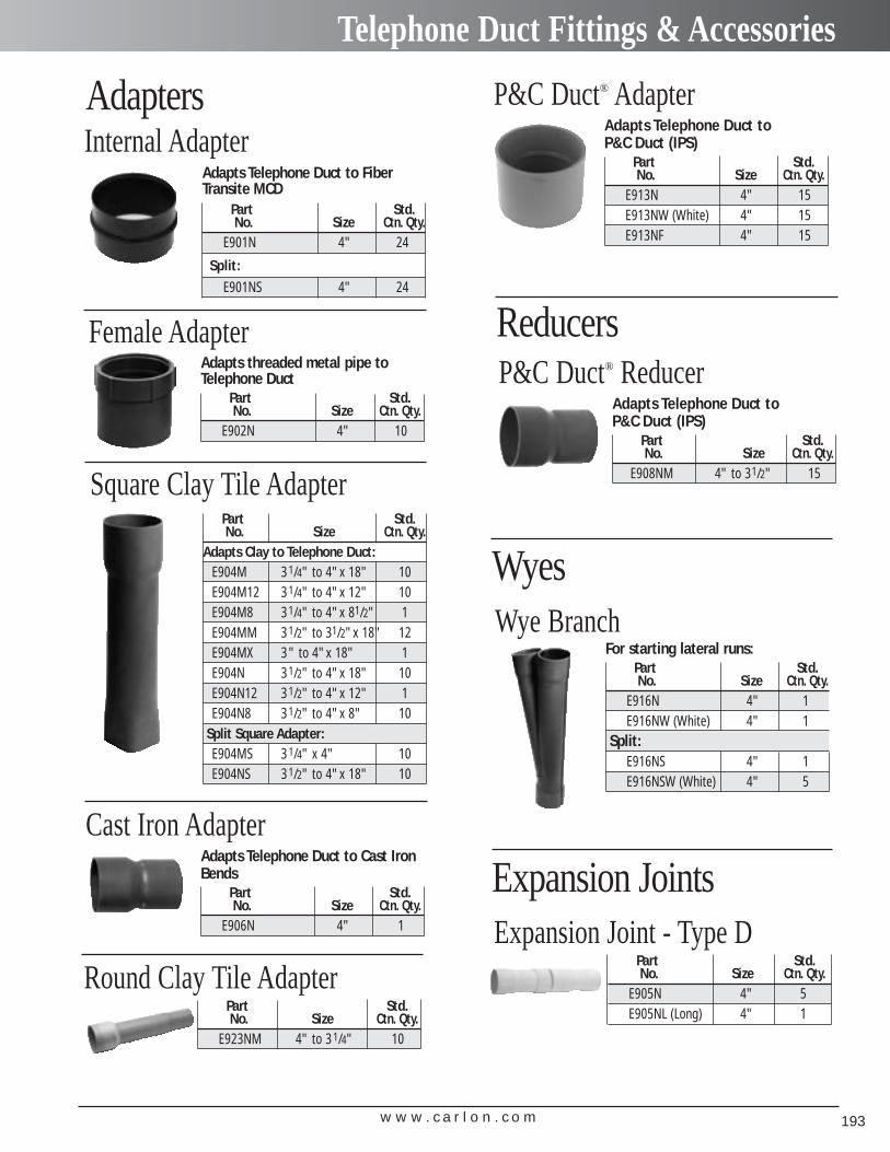
w w w . c a r l o n . c o m 193
Telephone Duct Fittings & Accessories
Adapts Telephone Duct to FiberTransite MCD
Part Std.No. Size Ctn. Qty.
E901N 4" 24
Split:E901NS 4" 24
Internal Adapter
Adapts threaded metal pipe toTelephone Duct
Part Std.No. Size Ctn. Qty.
E902N 4" 10
Female Adapter
Adapts Telephone Duct to Cast IronBends
Part Std.No. Size Ctn. Qty.
E906N 4" 1
Cast Iron Adapter
Adapts Telephone Duct to P&C Duct (IPS)
Part Std.No. Size Ctn. Qty.
E908NM 4" to 31/2" 15
P&C Duct® Reducer
Square Clay Tile Adapter
Adapts Telephone Duct to P&C Duct (IPS)
Part Std.No. Size Ctn. Qty.
E913N 4" 15E913NW (White) 4" 15E913NF 4" 15
P&C Duct® Adapter
For starting lateral runs:Part Std.No. Size Ctn. Qty.
E916N 4" 1E916NW (White) 4" 1
Split:E916NS 4" 1E916NSW (White) 4" 5
Wye Branch
Part Std.No. Size Ctn. Qty.
E923NM 4" to 31/4" 10
Round Clay Tile AdapterPart Std.No. Size Ctn. Qty.
E905N 4" 5E905NL (Long) 4" 1
Expansion Joint - Type D
Reducers
Adapters
Wyes
Expansion Joints
Part Std.No. Size Ctn. Qty.
Adapts Clay to Telephone Duct:E904M 31/4" to 4"x 18" 10E904M12 31/4" to 4"x 12" 10E904M8 31/4" to 4"x 81/2" 1E904MM 31/2" to 31/2"x 18" 12E904MX 3" to 4"x 18" 1E904N 31/2" to 4"x 18" 10E904N12 31/2" to 4"x 12" 1E904N8 31/2" to 4"x 8" 10
Split Square Adapter:E904MS 31/4" x 4" 10E904NS 31/2" to 4"x 18" 10
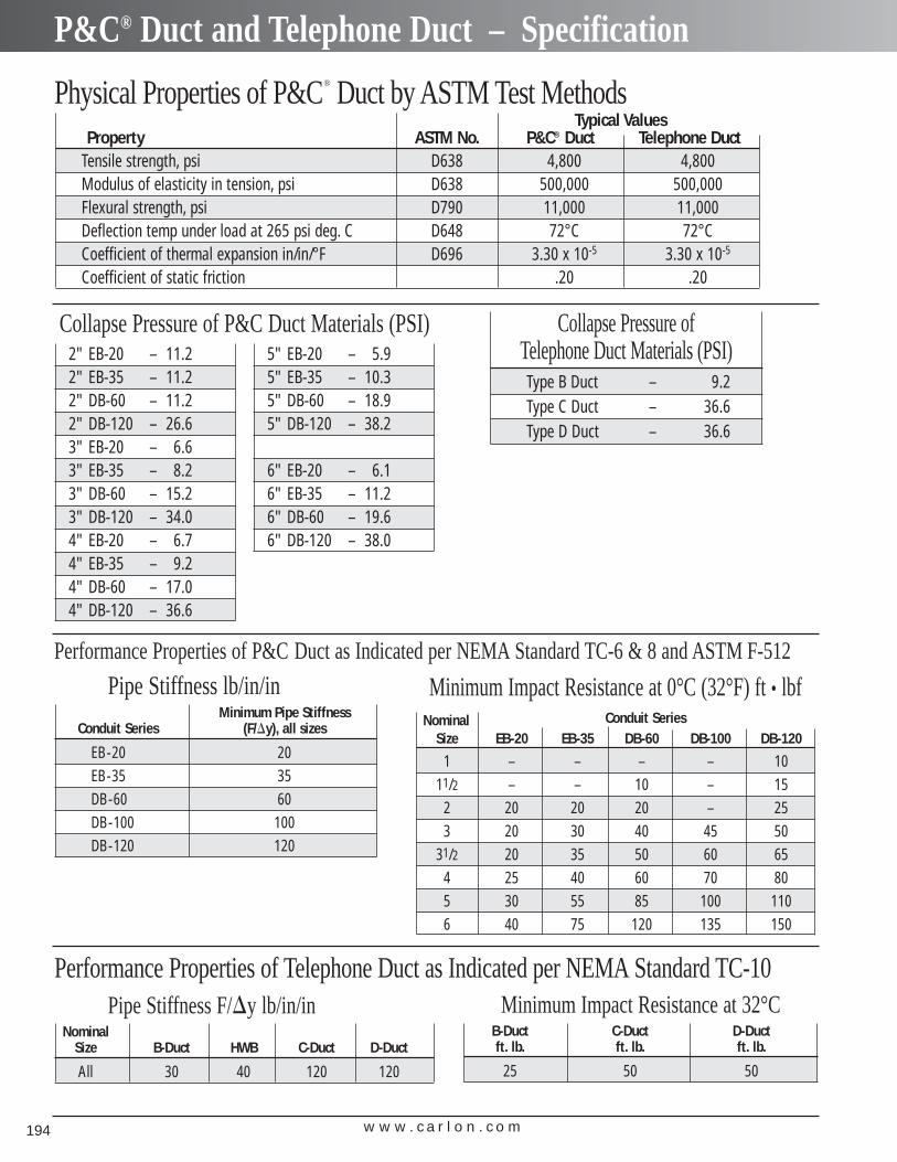
w w w . c a r l o n . c o m194
P&C® Duct and Telephone Duct – Specification
Physical Properties of P&C® Duct by ASTM Test MethodsTypical Values
Property ASTM No. P&C® Duct Telephone DuctTensile strength, psi D638 4,800 4,800Modulus of elasticity in tension, psi D638 500,000 500,000Flexural strength, psi D790 11,000 11,000Deflection temp under load at 265 psi deg. C D648 72°C 72°CCoefficient of thermal expansion in/in/°F D696 3.30 x 10⁻⁵ 3.30 x 10⁻⁵
Coefficient of static friction .20 .20
Minimum Impact Resistance at 0°C (32°F) ft • lbfNominal Conduit Series
Size EB-20 EB-35 DB-60 DB-100 DB-120
1 – – – – 1011/2 – – 10 – 15
2 20 20 20 – 253 20 30 40 45 50
31/2 20 35 50 60 654 25 40 60 70 805 30 55 85 100 1106 40 75 120 135 150
Performance Properties of P&C Duct as Indicated per NEMA Standard TC-6 & 8 and ASTM F-512
Pipe Stiffness lb/in/inMinimum Pipe Stiffness
Conduit Series (F/�y), all sizes
EB-20 20EB-35 35DB-60 60DB-100 100DB-120 120
Minimum Impact Resistance at 32°CB-Duct C-Duct D-Ductft. lb. ft. lb. ft. lb.
25 50 50
Performance Properties of Telephone Duct as Indicated per NEMA Standard TC-10Pipe Stiffness F/�y lb/in/in
NominalSize B-Duct HWB C-Duct D-Duct
All 30 40 120 120
Collapse Pressure of Telephone Duct Materials (PSI)Type B Duct – 9.2Type C Duct – 36.6Type D Duct – 36.6
2" EB-20 – 11.22" EB-35 – 11.22" DB-60 – 11.22" DB-120 – 26.63" EB-20 – 6.63" EB-35 – 8.23" DB-60 – 15.23" DB-120 – 34.04" EB-20 – 6.74" EB-35 – 9.24" DB-60 – 17.04" DB-120 – 36.6
5" EB-20 – 5.95" EB-35 – 10.35" DB-60 – 18.95" DB-120 – 38.2
6" EB-20 – 6.16" EB-35 – 11.26" DB-60 – 19.66" DB-120 – 38.0
Collapse Pressure of P&C Duct Materials (PSI)
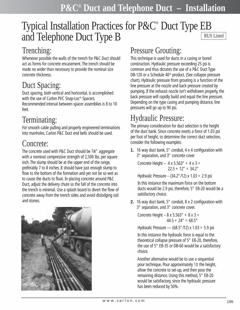
w w w . c a r l o n . c o m 195
P&C® Duct and Telephone Duct – Installation
Typical Installation Practices for P&C® Duct Type EBand Telephone Duct Type BTrenching:Whenever possible the walls of the trench for P&C Duct shouldact as forms for concrete encasement. The trench should bemade no wider than necessary to provide the nominal sizeconcrete thickness.
Duct Spacing:Duct spacing, both vertical and horizontal, is accomplishedwith the use of Carlon PVC Snap-Loc® Spacers.Recommended interval between spacer assemblies is 8 to 10feet.
Terminating:For smooth cable pulling and properly engineered terminationsinto manholes, Carlon P&C Duct end bells should be used.
Concrete:The concrete used with P&C Duct should be 3/8" aggregatewith a nominal compressive strength of 2,500 lbs. per squareinch. The slump should be at the upper end of the range,preferably 7 to 8 inches. It should have just enough slump toflow to the bottom of the formation and yet not be so wet asto cause the ducts to float. In placing concrete around P&CDuct, adjust the delivery chute so the fall of the concrete intothe trench is minimal. Use a splash board to divert the flow ofconcrete away from the trench sides and avoid dislodging soiland stones.
Pressure Grouting:This technique is used for ducts in a casing or bored construction. Hydraulic pressure exceeding 25 psi is common and thus dictates the use of a P&C Duct Type DB-120 or a Schedule 40® product. (See collapse pressurechart). Hydraulic pressure from grouting is a function of theline pressure at the nozzle and back pressure created bypumping. If the exhaust nozzle isn’t withdrawn properly, theback pressure will rapidly build and equal the line pressure.Depending on the type casing and pumping distance, linepressures will go up to 90 psi.
Hydraulic Pressure:The primary consideration for duct selection is the height of the duct bank. Since concrete exerts a force of 1.03 psiper foot of height, to determine the correct duct selection,consider the following examples:
1. 16 way duct bank, 5" conduit, 4 x 4 configuration with3" separation, and 3" concrete cover
Concrete Height – 4 x 5.563" + 4 x 3 =22.5 + 12" = 34.2"
Hydraulic Pressure – (34.2"/12) x 1.03 = 2.9 psi
In this instance the maximum force on the bottomducts would be 2.9 psi, therefore, 5" EB-20 would be a satisfactory choice.
2. 16 way duct bank, 5" conduit, 8 x 2 configuration with3" separation, and 3" concrete cover.
Concrete Height – 8 x 5.563" + 8 x 3 =44.5 + 24" = 68.5"
Hydraulic Pressure — (68.5"/12) x 1.03 = 5.9 psi
In this instance the hydraulic force is equal to the theoretical collapse pressure of 5" EB-20, therefore,the use of 5" EB-35 or DB-60 would be a satisfactorychoice.
Another alternative would be to use a sequential pour technique. Pour approximately 1/2 the height,allow the concrete to set-up, and then pour the remaining distance. Using this method, 5" EB-20 would be satisfactory, since the hydraulic pressure has been reduced by 50%.
RUS Listed
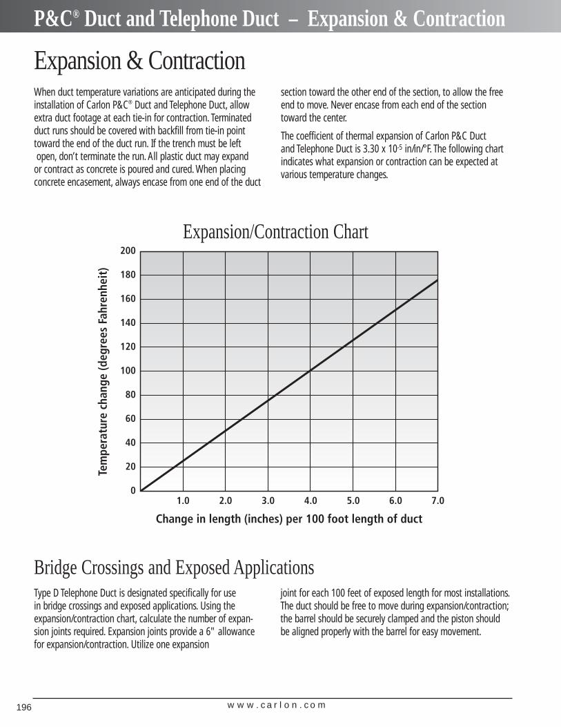
w w w . c a r l o n . c o m196
P&C® Duct and Telephone Duct – Expansion & Contraction
Expansion & ContractionWhen duct temperature variations are anticipated during theinstallation of Carlon P&C® Duct and Telephone Duct, allowextra duct footage at each tie-in for contraction. Terminatedduct runs should be covered with backfill from tie-in pointtoward the end of the duct run. If the trench must be leftopen, don’t terminate the run. All plastic duct may expand
or contract as concrete is poured and cured. When placing concrete encasement, always encase from one end of the duct
section toward the other end of the section, to allow the freeend to move. Never encase from each end of the sectiontoward the center.
The coefficient of thermal expansion of Carlon P&C Duct and Telephone Duct is 3.30 x 10⁻⁵ in/in/°F. The following chartindicates what expansion or contraction can be expected atvarious temperature changes.
Type D Telephone Duct is designated specifically for use in bridge crossings and exposed applications. Using the expansion/contraction chart, calculate the number of expan-sion joints required. Expansion joints provide a 6" allowancefor expansion/contraction. Utilize one expansion
joint for each 100 feet of exposed length for most installations.The duct should be free to move during expansion/contraction;the barrel should be securely clamped and the piston shouldbe aligned properly with the barrel for easy movement.
Bridge Crossings and Exposed Applications
Expansion/Contraction Chart
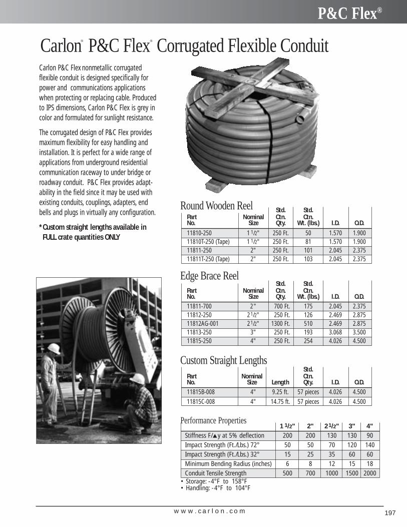
w w w . c a r l o n . c o m 197
P&C Flex®
Carlon® P&C Flex® Corrugated Flexible ConduitCarlon P&C Flex nonmetallic corrugated flexible conduit is designed specifically forpower and communications applicationswhen protecting or replacing cable. Producedto IPS dimensions, Carlon P&C Flex is grey incolor and formulated for sunlight resistance.
The corrugated design of P&C Flex providesmaximum flexibility for easy handling andinstallation. It is perfect for a wide range ofapplications from underground residential communication raceway to under bridge orroadway conduit. P&C Flex provides adapt-ability in the field since it may be used withexisting conduits, couplings, adapters, endbells and plugs in virtually any configuration.
*Custom straight lengths available in FULL crate quantities ONLY
Performance Properties1 1/2" 2" 21/2" 3" 4"
Stiffness F/▲y at 5% deflection 200 200 130 130 90Impact Strength (Ft./Lbs.) 72° 50 50 70 120 140Impact Strength (Ft./Lbs.) 32° 15 25 35 60 60Minimum Bending Radius (inches) 6 8 12 15 18Conduit Tensile Strength 500 700 1000 1500 2000
• Storage: -4°F to 158°F• Handling: -4°F to 104°F
Round Wooden Reel
Edge Brace ReelStd. Std.
Part Nominal Ctn. Ctn.No. Size Qty. Wt. (lbs.) I.D. O.D.11811-700 2" 700 Ft. 175 2.045 2.37511812-250 21/2" 250 Ft. 126 2.469 2.87511812AG-001 21/2" 1300 Ft. 510 2.469 2.87511813-250 3" 250 Ft. 193 3.068 3.50011815-250 4" 250 Ft. 254 4.026 4.500
Std. Std.Part Nominal Ctn. Ctn.No. Size Qty. Wt. (lbs.) I.D. O.D.
11810-250 1 1/2" 250 Ft. 50 1.570 1.90011810T-250 (Tape) 1 1/2" 250 Ft. 81 1.570 1.90011811-250 2" 250 Ft. 101 2.045 2.37511811T-250 (Tape) 2" 250 Ft. 103 2.045 2.375
Custom Straight LengthsStd.
Part Nominal Ctn.No. Size Length Qty. I.D. O.D.11815B-008 4" 9.25 ft. 57 pieces 4.026 4.50011815C-008 4" 14.75 ft. 57 pieces 4.026 4.500
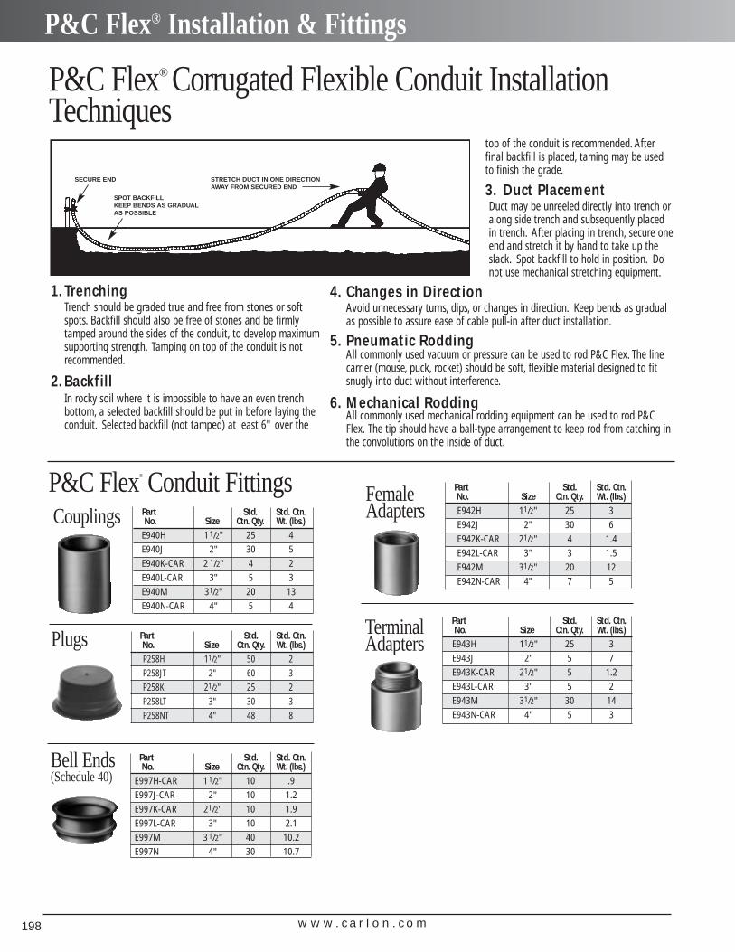
w w w . c a r l o n . c o m198
P&C Flex® Installation & Fittings
Part Std. Std. Ctn.No. Size Ctn. Qty. Wt. (lbs.)
E940H 11/2" 25 4E940J 2" 30 5E940K-CAR 2 1/2" 4 2E940L-CAR 3" 5 3E940M 31/2" 20 13E940N-CAR 4" 5 4
Couplings
Part Std. Std. Ctn.No. Size Ctn. Qty. Wt. (lbs.)P258H 11/2" 50 2P258JT 2" 60 3P258K 21/2" 25 2P258LT 3" 30 3P258NT 4" 48 8
Plugs
1.TrenchingTrench should be graded true and free from stones or softspots. Backfill should also be free of stones and be firmlytamped around the sides of the conduit, to develop maximumsupporting strength. Tamping on top of the conduit is not recommended.
2.Backfill In rocky soil where it is impossible to have an even trenchbottom, a selected backfill should be put in before laying theconduit. Selected backfill (not tamped) at least 6" over the
top of the conduit is recommended. Afterfinal backfill is placed, taming may be usedto finish the grade.
3. Duct Placement Duct may be unreeled directly into trench oralong side trench and subsequently placedin trench. After placing in trench, secure oneend and stretch it by hand to take up theslack. Spot backfill to hold in position. Donot use mechanical stretching equipment.
4. Changes in Direction Avoid unnecessary turns, dips, or changes in direction. Keep bends as gradualas possible to assure ease of cable pull-in after duct installation.
5. Pneumatic Rodding All commonly used vacuum or pressure can be used to rod P&C Flex. The linecarrier (mouse, puck, rocket) should be soft, flexible material designed to fitsnugly into duct without interference.
6. Mechanical Rodding All commonly used mechanical rodding equipment can be used to rod P&CFlex. The tip should have a ball-type arrangement to keep rod from catching inthe convolutions on the inside of duct.
P&C Flex® Conduit Fittings
Part Std. Std. Ctn.No. Size Ctn. Qty. Wt. (lbs.)
E997H-CAR 11/2" 10 .9E997J-CAR 2" 10 1.2E997K-CAR 21/2" 10 1.9E997L-CAR 3" 10 2.1E997M 31/2" 40 10.2E997N 4" 30 10.7
Bell Ends(Schedule 40)
Part Std. Std. Ctn.No. Size Ctn. Qty. Wt. (lbs.)E942H 11/2" 25 3E942J 2" 30 6E942K-CAR 21/2" 4 1.4E942L-CAR 3" 3 1.5E942M 31/2" 20 12E942N-CAR 4" 7 5
FemaleAdapters
Part Std. Std. Ctn.No. Size Ctn. Qty. Wt. (lbs.)E943H 11/2" 25 3E943J 2" 5 7E943K-CAR 21/2" 5 1.2E943L-CAR 3" 5 2E943M 31/2" 30 14E943N-CAR 4" 5 3
TerminalAdapters
P&C Flex® Corrugated Flexible Conduit InstallationTechniques
STRETCH DUCT IN ONE DIRECTIONAWAY FROM SECURED END
SPOT BACKFILLKEEP BENDS AS GRADUALAS POSSIBLE
SECURE END
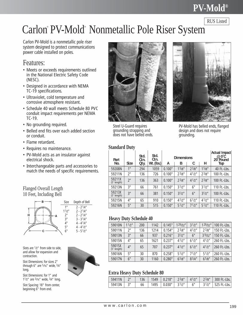
w w w . c a r l o n . c o m 199
PV-Mold®
Carlon® PV-Mold® Nonmetallic Pole Riser SystemRUS Listed
Carlon PV-Mold is a nonmetallic pole risersystem designed to protect communicationspower cable installed on poles.
Features:• Meets or exceeds requirements outlined
in the National Electric Safety Code(NESC).
• Designed in accordance with NEMA TC-19 specifications.
• Ultraviolet, cold temperature and corrosive atmosphere resistant.
• Schedule 40 wall meets Schedule 80 PVCconduit impact requirements per NEMATC-19.
• No grounding required.• Belled end fits over each added section
or conduit.• Flame retardant.• Requires no maintenance.• PV-Mold acts as an insulator against
electrical shock.• Interchangeable parts and accessories to
match the needs of specific requirements.
Steel U-Guard requiresgrounding strapping anddoes not have belled ends.
PV-Mold has belled ends, flangeddesign and does not requiregrounding.
Flanged Overall Length10 Feet, Including Bell
Size Depth of Bell1" 2 - 21/4"
11/2" 2 - 21/4"2" 2 - 21/4"3" 3 - 31/4"4" 4 - 41/4"5" 4 - 41/2"6" 5 - 51/2"
Slots are 1/2" from side to side,and allow for expansion andcontraction.
Slot Dimensions: for sizes 2"through 6" are 5/16" wide, 3/4"long.
Slot Dimensions: for 1" and11/2" are 3/16" wide, 3/4" long.
Slot Spacing: 18" from center,beginning 6" from end.
Actual ImpactStd. Std. @ 0˚C
Part Ctn. Ctn. Dimensions 20 Pound No. Size Qty. Wt. (lbs.) A B C H Tup
59208N 1" 294 1059 0.100" 15/8" 23/8" 15/8" 40 Ft.-Lbs.59211N 2" 136 726 0.100" 23/8" 41/2" 23/8" 100 Ft.-Lbs.59211X 2" 136 363 0.100" 23/8" 41/2" 23/8" 100 Ft.-Lbs.(5' length)
59213N 3" 66 761 0.150" 31/2" 6" 31/2" 110 Ft.-Lbs.59213X 3" 66 381 0.150" 31/2" 6" 31/2" 100 Ft.-Lbs.(5' length)
59215N 4" 65 910 0.150" 41/2" 61/2" 41/2" 110 Ft.-Lbs.59216N 5" 30 515 0.150" 51/2" 71/2" 51/2" 110 Ft.-Lbs.
Standard Duty
59411N 2" 136 1549 0.218" 23/8" 41/2" 23/8" 300 Ft.-Lbs.59413N 3" 66 1495 0.030" 31/2" 6" 31/2" 525 Ft.-Lbs.
Extra Heavy Duty Schedule 80
59010N 11/2" 200 1142 0.145" 129/32" 31/2" 129/32" 100 Ft.-Lbs.59011N 2" 136 1214 0.154" 2 3/8" 41/2" 2 3/8" 150 Ft.-Lbs.59013N 3" 66 937 0.216" 31/2" 6" 3 9/32" 150 Ft.-Lbs.59015N 4" 65 1621 0.237" 41/2" 61/2" 41/2" 260 Ft.-Lbs.59015X 4" 65 707 0.237" 41/2" 61/2" 41/2" 260 Ft.-Lbs.(5' length)
59016N 5" 30 870 0.258" 51/2" 71/2" 51/2" 260 Ft.-Lbs.59017N 6" 30 1160 0.280" 65/8" 83/4" 65/8" 260 Ft.-Lbs.
Heavy Duty Schedule 40
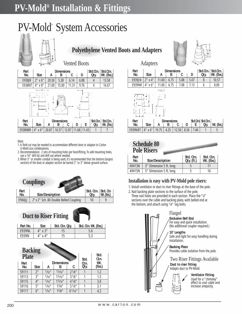
w w w . c a r l o n . c o m200
PV-Mold® Installation & Fittings
PV-Mold® System Accessories
Polyethylene Vented Boots and Adapters
Installation is easy with PV-Mold pole risers:1. Install ventilator or duct to riser fittings at the base of the pole.2. Nail backing plate sections to the surface of the pole.
Three nail holes are provided in each section. Place the “U”sections over the cable and backing plate, with belled end atthe bottom, and attach using 1/4" lag bolts.
FlangedExclusive Bell EndFor easy and quick installation.(No additional coupler required.)
10' LengthsSafe and light for easy handling during installation.
Backing PlateProvides cable isolation from the pole.
Two Riser Fittings AvailableDuct to riser fittingAdapts duct to PV-Mold.
Ventilator FittingUsed for a “chimney”effect to cool cable and increase ampacity.
Part No. Size Std. Ctn. Qty. Std. Ctn. Wt. (lbs.)E939NL 4" x 3" 15 5.6E939N 4" x 4" 15 5.3
Duct to Riser Fitting
Part Std. Ctn. Std. Ctn No. Size/Description Qty. Wt. (lbs.)
E966JJ 2"x 2" Sch. 80 Double Belled Coupling 10 9
Couplings
Std.Std. Ctn.
Part Dimensions Ctn. Wt.No. Size A B C Qty. (lbs.)
59111 2" 1/16" 13/16" 21/8" 1 1.259113 3" 1/16" 15/16" 31/8" 1 1.559115 4" 1/16" 15/16" 41/8" 1 3.059116 5" 1/16" 13/4" 51/4" 1 3.159117 6" 1/16" 15/8" 61/16" 1 4.2
BackingPlate
Part Std. Ctn. Std. Ctn.No. Size/Description Qty. (ft.) Wt. (lbs.)
49413N 3" Dimension 5 ft. long 5 1149415N 5" Dimension 5 ft. long 5 16
Schedule 80Pole Risers
Part Dimensions Std.Ctn. Std.Ctn.No. Size A B C D Qty. Wt. (lbs.)
E939JN 2" x 4" 11.00 6.75 5.88 5.07 8 10.57E939NR 4" x 6" 11.00 6.75 7.08 7.13 6 8.00
Adapters
Part Dimensions Std.Ctn. Std.Ctn.No. Size A B C D E Qty. Wt. (lbs.)
E939NRT 4" x 6" 19.75 4.25 12.50 8.50 7.40 1 5
Part Dimensions Std.Ctn. Std.Ctn.No. Size A B C D E Qty. Wt. (lbs.)
E938NRR 4" x 6" 20.87 16.57 12.87 11.68 11.43 1 7
Part Dimensions Std.Ctn. Std.Ctn.No. Size A B C D Qty. Wt. (lbs.)
E938JR 2" x 6" 20.50 5.38 6.14 6.88 4 13.58E938NT 4" x 8" 21.00 15.00 11.31 9.76 4 16.67
Vented Boots
Note:1. A field cut may be needed to accommodate different boot or adapter to Carlon
U-Mold size combinations.2. Recommendation: 2 sets of mounting holes per boot/fitting. To add mounting holes,
use a 3/8" drill bit and drill out where needed.3. When 3" or smaller conduit is being used, it’s recommended that the bottom (largest
section) of the boot or adapter section be buried 2" to 3" below ground surface.
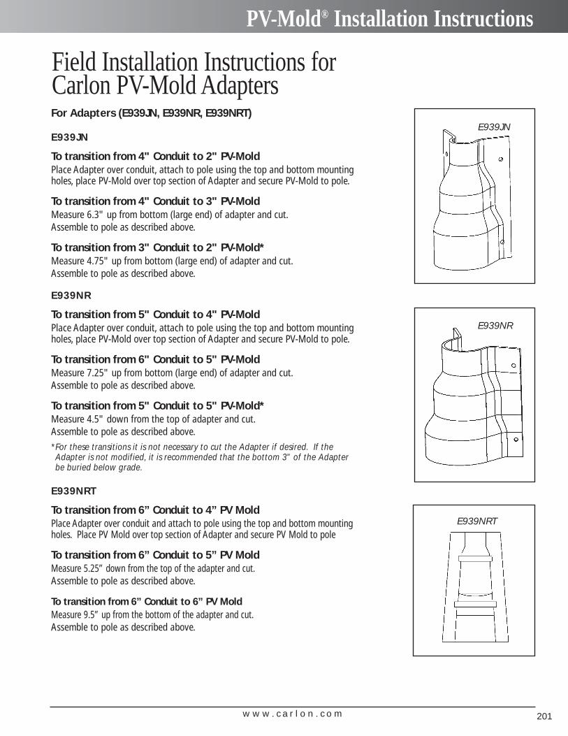
w w w . c a r l o n . c o m 201
PV-Mold® Installation Instructions
For Adapters (E939JN, E939NR, E939NRT)
E939JN
To transition from 4" Conduit to 2" PV-MoldPlace Adapter over conduit, attach to pole using the top and bottom mountingholes, place PV-Mold over top section of Adapter and secure PV-Mold to pole.
To transition from 4" Conduit to 3" PV-MoldMeasure 6.3" up from bottom (large end) of adapter and cut.Assemble to pole as described above.
To transition from 3" Conduit to 2" PV-Mold*Measure 4.75" up from bottom (large end) of adapter and cut.Assemble to pole as described above.
E939NR
To transition from 5" Conduit to 4" PV-MoldPlace Adapter over conduit, attach to pole using the top and bottom mountingholes, place PV-Mold over top section of Adapter and secure PV-Mold to pole.
To transition from 6" Conduit to 5" PV-MoldMeasure 7.25" up from bottom (large end) of adapter and cut.Assemble to pole as described above.
To transition from 5" Conduit to 5" PV-Mold*Measure 4.5" down from the top of adapter and cut.Assemble to pole as described above.*For these transitions it is not necessary to cut the Adapter if desired. If theAdapter is not modified, it is recommended that the bottom 3" of the Adapterbe buried below grade.
E939NRT
To transition from 6” Conduit to 4” PV MoldPlace Adapter over conduit and attach to pole using the top and bottom mountingholes. Place PV Mold over top section of Adapter and secure PV Mold to pole
To transition from 6” Conduit to 5” PV MoldMeasure 5.25” down from the top of the adapter and cut.Assemble to pole as described above.
To transition from 6” Conduit to 6” PV MoldMeasure 9.5” up from the bottom of the adapter and cut.Assemble to pole as described above.
E939JN
E939NR
Field Installation Instructions forCarlon PV-Mold Adapters
E939NRT
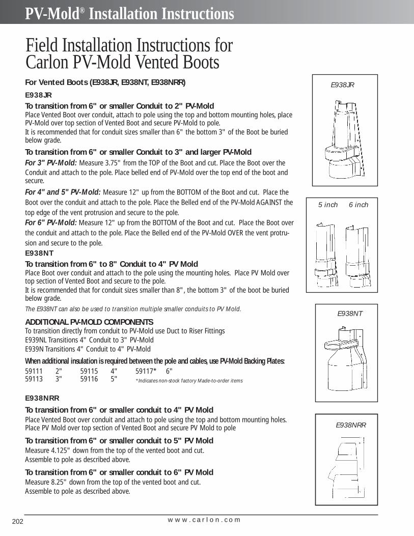
w w w . c a r l o n . c o m202
PV-Mold® Installation Instructions
For Vented Boots (E938JR, E938NT, E938NRR)
E938JRTo transition from 6" or smaller Conduit to 2" PV-MoldPlace Vented Boot over conduit, attach to pole using the top and bottom mounting holes, placePV-Mold over top section of Vented Boot and secure PV-Mold to pole.It is recommended that for conduit sizes smaller than 6" the bottom 3" of the Boot be buriedbelow grade.
To transition from 6" or smaller Conduit to 3" and larger PV-MoldFor 3" PV-Mold: Measure 3.75" from the TOP of the Boot and cut. Place the Boot over theConduit and attach to the pole. Place belled end of PV-Mold over the top end of the boot andsecure.
For 4" and 5" PV-Mold: Measure 12" up from the BOTTOM of the Boot and cut. Place theBoot over the conduit and attach to the pole. Place the Belled end of the PV-Mold AGAINST thetop edge of the vent protrusion and secure to the pole.For 6" PV-Mold: Measure 12" up from the BOTTOM of the Boot and cut. Place the Boot overthe conduit and attach to the pole. Place the Belled end of the PV-Mold OVER the vent protru-sion and secure to the pole.E938NTTo transition from 6" to 8" Conduit to 4" PV MoldPlace Boot over conduit and attach to the pole using the mounting holes. Place PV Mold overtop section of Vented Boot and secure to the pole.It is recommended that for conduit sizes smaller than 8", the bottom 3" of the boot be buriedbelow grade.The E938NT can also be used to transition multiple smaller conduits to PV Mold.
ADDITIONAL PV-MOLD COMPONENTSTo transition directly from conduit to PV-Mold use Duct to Riser FittingsE939NL Transitions 4" Conduit to 3" PV-MoldE939N Transitions 4" Conduit to 4" PV-Mold
When additional insulation is required between the pole and cables, use PV-Mold Backing Plates:
E938JR
E938NT
59111 2"59113 3"
59115 4"59116 5"
59117* 6"*Indicates non-stock factory Made-to-order items
5 inch 6 inch
Field Installation Instructions forCarlon PV-Mold Vented Boots
E938NRR
E938NRR
To transition from 6" or smaller conduit to 4" PV MoldPlace Vented Boot over conduit and attach to pole using the top and bottom mounting holes.Place PV Mold over top section of Vented Boot and secure PV Mold to pole
To transition from 6" or smaller conduit to 5" PV MoldMeasure 4.125" down from the top of the vented boot and cut.Assemble to pole as described above.
To transition from 6" or smaller conduit to 6" PV MoldMeasure 8.25" down from the top of the vented boot and cut.Assemble to pole as described above.
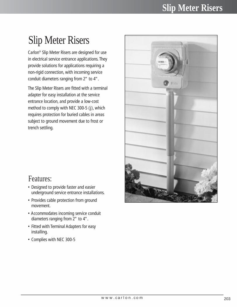
w w w . c a r l o n . c o m 203
Slip Meter Risers
Carlon® Slip Meter Risers are designed for usein electrical service entrance applications. Theyprovide solutions for applications requiring anon-rigid connection, with incoming serviceconduit diameters ranging from 2" to 4".
The Slip Meter Risers are fitted with a terminaladapter for easy installation at the serviceentrance location, and provide a low-costmethod to comply with NEC 300-5 (j), whichrequires protection for buried cables in areassubject to ground movement due to frost ortrench settling.
• Designed to provide faster and easier underground service entrance installations.
• Provides cable protection from ground movement.
• Accommodates incoming service conduit diameters ranging from 2" to 4".
• Fitted with Terminal Adapters for easyinstalling.
• Complies with NEC 300-5
Features:
Slip Meter Risers
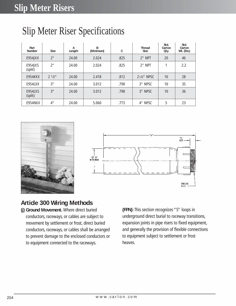
w w w . c a r l o n . c o m204
Slip Meter Risers
Std. Std.Part A B Thread Carton Carton
Number Size Length (Minimum) C Size Qty. Wt. (lbs.)
E954JXX 2" 24.00 2.024 .825 2" NPT 20 46
E954JXS 2" 24.00 2.024 .825 2" NPT 1 2.2(split)
E954KXX 2 1/2" 24.00 2.418 .812 21/2" NPSC 10 28
E954LXX 3" 24.00 3.012 .798 3" NPSC 10 35
E954LXS 3" 24.00 3.012 .798 3" NPSC 10 36(split)
E954NXX 4" 24.00 5.060 .773 4" NPSC 5 23
Article 300 Wiring Methods(j) Ground Movement. Where direct buried
conductors, raceways, or cables are subject tomovement by settlement or frost, direct buriedconductors, raceways, or cables shall be arrangedto prevent damage to the enclosed conductors orto equipment connected to the raceways.
(FPN): This section recognizes “S” loops in underground direct burial to raceway transitions,expansion joints in pipe risers to fixed equipment,and generally the provision of flexible connectionsto equipment subject to settlement or frostheaves.
Slip Meter Riser Specifications
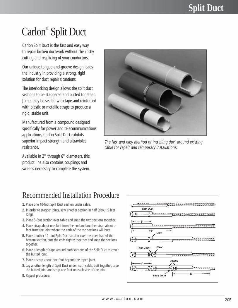
w w w . c a r l o n . c o m 205
Split Duct
Carlon Split Duct is the fast and easy way to repair broken ductwork without the costlycutting and resplicing of your conductors.
Our unique tongue-and-groove design leadsthe industry in providing a strong, rigid solution for duct repair situations.
The interlocking design allows the split ductsections to be staggered and butted together.Joints may be sealed with tape and reinforcedwith plastic or metallic straps to produce arigid, stable unit.
Manufactured from a compound designedspecifically for power and telecommunicationsapplications, Carlon Split Duct exhibits superior impact strength and ultraviolet resistance.
Available in 2" through 6" diameters, thisproduct line also contains couplings andsweeps necessary to complete the system.
Carlon® Split Duct
The fast and easy method of installing duct around existingcable for repair and temporary installations.
Recommended Installation Procedure1. Place one 10-foot Split Duct section under cable.2. In order to stagger joints, saw another section in half (about 5 feet
long).3. Place 5-foot sectIon over cable and snap the two sections together.4. Place strap about one foot from the end and another strap about a
foot from the joint where the ends of the top sections will butt.5. Place another 10-foot Split Duct section over the open half of the
bottom section, butt the ends tightly together and snap the sectionstogether.
6. Place a length of tape around both sections of the Split Duct to coverthe butted joint.
7. Place a strap about one foot beyond the taped joint.8. Lay another length of Split Duct underneath cable, butt together, tape
the butted joint and strap one foot on each side of the joint.9. Repeat procedure.
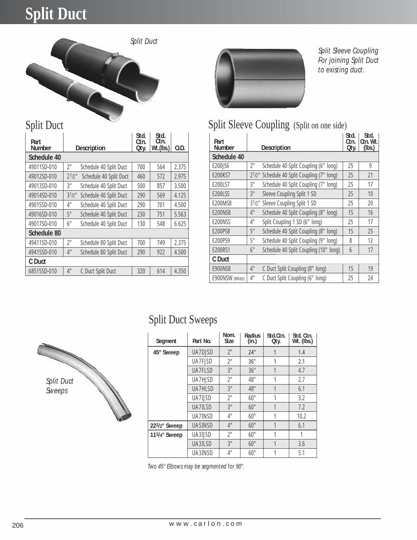
w w w . c a r l o n . c o m206
Split Duct
Split Duct
Split Sleeve Coupling For joining Split Ductto existing duct.
Split DuctSweeps
Split Duct
Std. Std.Part Ctn. Ctn.Number Description Qty. Wt.(lbs.) O.D.
Schedule 4049011SD-010 2" Schedule 40 Split Duct 700 564 2.37549012SD-010 21/2" Schedule 40 Split Duct 460 572 2.97549013SD-010 3" Schedule 40 Split Duct 500 857 3.50049014SD-010 31/2" Schedule 40 Split Duct 290 569 4.12549015SD-010 4" Schedule 40 Split Duct 290 701 4.50049016SD-010 5" Schedule 40 Split Duct 230 751 5.56349017SD-010 6" Schedule 40 Split Duct 130 548 6.625Schedule 8049411SD-010 2" Schedule 80 Split Duct 700 749 2.37549415SD-010 4" Schedule 80 Split Duct 290 922 4.500C Duct68515SD-010 4" C Duct Split Duct 320 614 4.350
Split Sleeve Coupling (Split on one side)
Split Duct Sweeps
Two 45° Elbows may be segmented for 90°.
Nom. Radius Std.Ctn. Std. Ctn.Segment Part No. Size (in.) Qty. Wt. (lbs.)
45° Sweep UA7DJSD 2" 24" 1 1.4
UA7FJSD 2" 36" 1 2.1
UA7FLSD 3" 36" 1 4.7UA7HJSD 2" 48" 1 2.7UA7HLSD 3" 48" 1 6.1UA7IJSD 2" 60" 1 3.2UA7ILSD 3" 60" 1 7.2UA7INSD 4" 60" 1 10.2
221/2° Sweep UA5INSD 4" 60" 1 6.1111/4° Sweep UA3IJSD 2" 60" 1 1
UA3ILSD 3" 60" 1 3.6UA3INSD 4" 60" 1 5.1
Std. Std.Part Ctn. Ctn. Wt.Number Description Qty. (lbs.)
Schedule 40 and 80E200JS6 2" Schedule 40 Split Coupling (6" long) 25 9E200KS7 21/2" Schedule 40 Split Coupling (7" long) 25 21E200LS7 3" Schedule 40 Split Coupling (7" long) 25 17E200LSS 3" Sleeve Coupling Split 1 SD 25 10E200MS8 31/2" Sleeve Coupling Split 1 SD 25 20E200NS8 4" Schedule 40 Split Coupling (8" long) 15 16E200NSS 4" Split Coupling 1 SD (6" long) 25 17E200PS8 5" Schedule 40 Split Coupling (8" long) 15 25E200PS9 5" Schedule 40 Split Coupling (9" long) 8 12E200RS1 6" Schedule 40 Split Coupling (10" long) 6 17C DuctE900NS8 4" C Duct Split Coupling (8" long) 15 19E900NSW (White) 4" C Duct Split Coupling (6" long) 25 24
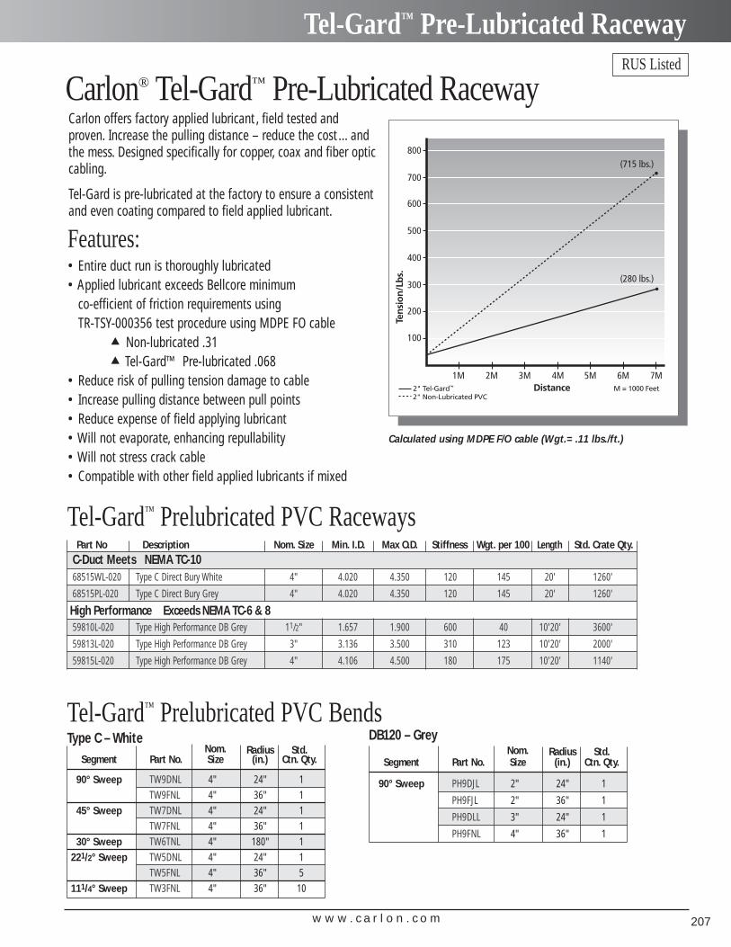
w w w . c a r l o n . c o m 207
Tel-Gard™ Pre-Lubricated Raceway
Carlon® Tel-Gard™ Pre-Lubricated RacewayCarlon offers factory applied lubricant , field tested andproven. Increase the pulling distance – reduce the cost ... andthe mess. Designed specifically for copper, coax and fiber opticcabling.
Tel-Gard is pre-lubricated at the factory to ensure a consistentand even coating compared to field applied lubricant.
Features:• Entire duct run is thoroughly lubricated• Applied lubricant exceeds Bellcore minimum
co-efficient of friction requirements using TR-TSY-000356 test procedure using MDPE FO cable
▲ Non-lubricated .31▲ Tel-Gard™ Pre-lubricated .068
• Reduce risk of pulling tension damage to cable• Increase pulling distance between pull points• Reduce expense of field applying lubricant• Will not evaporate, enhancing repullability• Will not stress crack cable• Compatible with other field applied lubricants if mixed
Calculated using MDPE F/O cable (Wgt.= .11 lbs./ft.)
Tel-Gard™ Prelubricated PVC Raceways
Tel-Gard™ Prelubricated PVC Bends Type C – White
Nom. Radius Std.Segment Part No. Size (in.) Ctn. Qty.
90° Sweep TW9DNL 4" 24" 1TW9FNL 4" 36" 1
45° Sweep TW7DNL 4" 24" 1TW7FNL 4" 36" 1
30° Sweep TW6TNL 4" 180" 1221/2° Sweep TW5DNL 4" 24" 1
TW5FNL 4" 36" 5111/4° Sweep TW3FNL 4" 36" 10
Nom. Radius Std.Segment Part No. Size (in.) Ctn. Qty.
90° Sweep PH9DJL 2" 24" 1
PH9FJL 2" 36" 1
PH9DLL 3" 24" 1
PH9FNL 4" 36" 1
DB120 – Grey
RUS Listed
Part No Description Nom. Size Min. I.D. Max O.D. Stiffness Wgt. per 100 Length Std. Crate Qty.C-Duct Meets NEMA TC-1068515WL-020 Type C Direct Bury White 4" 4.020 4.350 120 145 20' 1260'
68515PL-020 Type C Direct Bury Grey 4" 4.020 4.350 120 145 20' 1260'
59810L-020 Type High Performance DB Grey 11/2" 1.657 1.900 600 40 10'20' 3600'
59813L-020 Type High Performance DB Grey 3" 3.136 3.500 310 123 10'20' 2000'
59815L-020 Type High Performance DB Grey 4" 4.106 4.500 180 175 10'20' 1140'
High Performance Exceeds NEMA TC-6 & 8
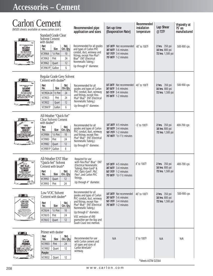
w w w . c a r l o n . c o m208
Accessories – Cement
Carlon® CementStandard Grade Clear Solvent Cement with dauber
Regular Grade Grey SolventCement with dauber*
All-Weather “Quick-Set”Clear Solvent Cement with dauber*
All-Weather ENT Blue “Quick-Set” SolventCement with brush*
Low VOC SolventCement with dauber*
Primer with dauber
Part Std.No. Size Ctn. Qty.
VC9964 1/2 Pint 10
VC9963 Pint 24
VC9962 Quart 12
VC9961P Gallon 6
Part Std.No. Size Ctn.Qty.
VC9924-24 1/2 Pint 24
VC9923 Pint 24
VC9922 Quart 12
VC9941P Gallon 6
Part Std.No. Size Ctn. Qty.
VC9984 1/2 Pint 10
VC9983 Pint 24
VC9982 Quart 12
VC9981P Gallon 6
Part Std.No. Size Ctn. Qty.
VC9992 Quart 12
VC9993 Pint 24
*Meets ASTM D2564
Recommended for all gradesand types of Carlon PVC conduit, duct, wireway and fittings, except Flex-Plus®
Blue™ ENT (ElectricalNonmetallic Tubing.) Up through 6" diameter.
Recommended for allgrades and types of CarlonPVC conduit, duct, wirewayand fittings, except Flex-Plus® Blue™ ENT (ElectricalNonmetallic Tubing.) Up through 6" diameter.
Recommended for allgrades and types of CarlonPVC conduit, duct, wirewayand fittings, except Flex-Plus® Blue™ ENT (ElectricalNonmetallic Tubing.) Up through 6" diameter.
Recommended for allgrades and types of CarlonPVC conduit, duct, wirewayand fittings, except Flex-Plus® Blue™ ENT (ElectricalNonmetallic Tubing.) Up through 6" diameter.VOC emission of 490grams/liter per the Bay andSouth Coast test method.
Required for use with Flex-Plus® Blue™ ENT(Electrical NonmetallicTubing), Riser-Gard® &PVC Optic-Gard®, P&CFlex®, and Carlon PVC fittings.Up through 4" diameter.
Recommended for usewith Carlon cement andall types and sizes ofCarlon WireSafe™
wireway.
Recommended pipeapplication and sizes
10˚-30˚F Not recommended30˚-50˚F 5-6 minutes50˚-70˚F 3-4 minutes70˚-90˚F 1-2 minutes
10˚-30˚F Not recommended30˚-50˚F 5-6 minutes50˚-70˚F 3-4 minutes70˚-90˚F 1-2 minutes
10˚-30˚F 4-5 minutes30˚-50˚F 3-4 minutes50˚-70˚F 1-2 minutes70˚-90˚F 1/2-11/2 minutes
10˚-30˚F 4-5 minutes30˚-50˚F 3-4 minutes50˚-70˚F 1-2 minutes70˚-90˚F 1/2-11/2 minutes
10˚-30˚F Not recommended30˚-50˚F 5-6 minutes50˚-70˚F 3-4 minutes70˚-90˚F 1-2 minutes
N/A
2 hrs. 350 psi16 hrs. 800 psi72 hrs. 1,500 psi
2 hrs. 350 psi16 hrs. 800 psi72 hrs. 1,500 psi
2 hrs. 350 psi16 hrs. 800 psi72 hrs. 1,500 psi
2 hrs. 350 psi16 hrs. 800 psi72 hrs. 1,500 psi
2 hrs. 350 psi16 hrs. 800 psi72 hrs. 1,500 psi
N/A
Set-up time(Evaporation Rate)
5˚ to 100˚F N/A
Lap Shear@ 73˚F
Part Std.No. Size Ctn. Qty.
VC9LV4 1/2 Pint 10
VC9LV3 Pint 24
VC9LV2 Quart 12
Recommendedinstallation temperature
40˚ to 100˚F
40˚ to 100˚F
-5˚ to 100˚F
4˚ to 100˚F
40˚ to 100˚F
Viscosity at 75˚ asmanufactured
500-900 cps
500-900 cps
400-700 cps
400-700 cps
500-900 cps
(MSDS sheets available at www.carlon.com )
Part Std.No. Size Ctn. Qty.
VC9903 Pint 24
VC9902 Quart 12Purple:
VC9932 Quart 12
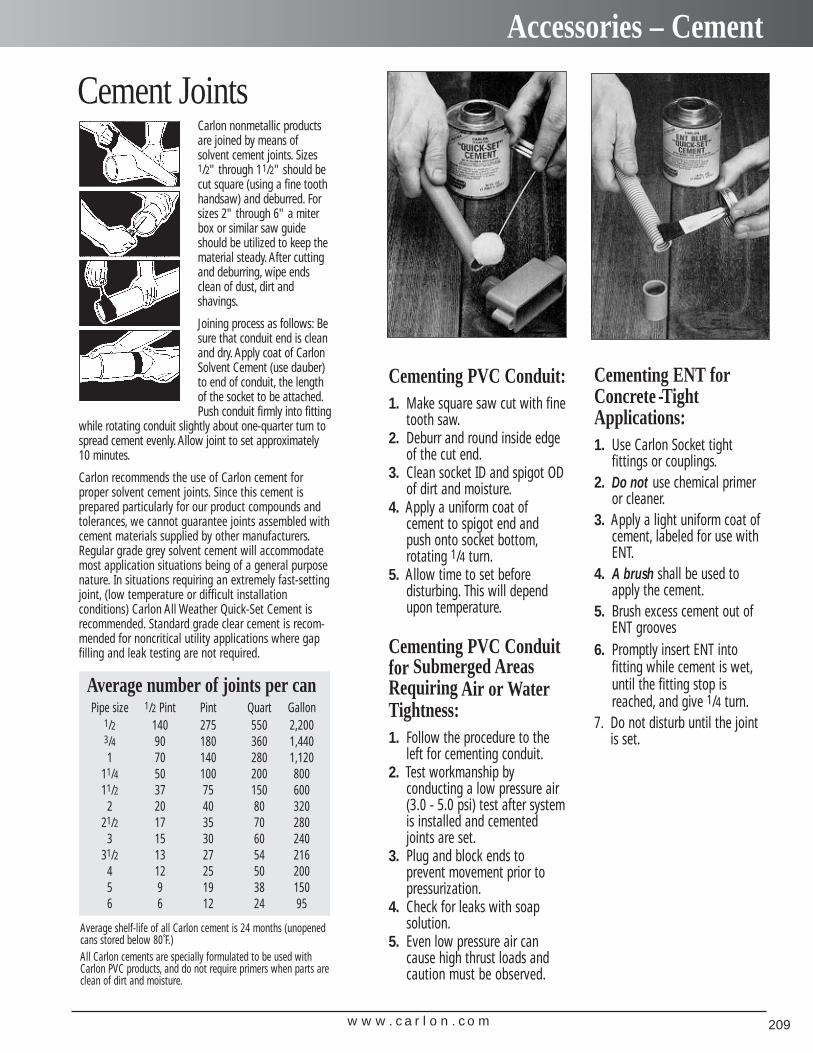
w w w . c a r l o n . c o m 209
Accessories – Cement
Average number of joints per canPipe size 1/2 Pint Pint Quart Gallon
1/2 140 275 550 2,2003/4 90 180 360 1,4401 70 140 280 1,120
11/4 50 100 200 80011/2 37 75 150 600
2 20 40 80 32021/2 17 35 70 280
3 15 30 60 24031/2 13 27 54 216
4 12 25 50 2005 9 19 38 1506 6 12 24 95
Average shelf-life of all Carlon cement is 24 months (unopenedcans stored below 80˚F.)All Carlon cements are specially formulated to be used withCarlon PVC products, and do not require primers when parts areclean of dirt and moisture.
Cementing PVC Conduit:1. Make square saw cut with fine
tooth saw.2. Deburr and round inside edge
of the cut end.3. Clean socket ID and spigot OD
of dirt and moisture.4. Apply a uniform coat of
cement to spigot end andpush onto socket bottom,rotating 1/4 turn.
5. Allow time to set before disturbing. This will depend upon temperature.
Cementing PVC Conduitfor Submerged AreasRequiring Air or WaterTightness:1. Follow the procedure to the
left for cementing conduit.2. Test workmanship by
conducting a low pressure air(3.0 - 5.0 psi) test after systemis installed and cementedjoints are set.
3. Plug and block ends to prevent movement prior topressurization.
4. Check for leaks with soap solution.
5. Even low pressure air cancause high thrust loads andcaution must be observed.
Cementing ENT forConcrete -TightApplications:1. Use Carlon Socket tight
fittings or couplings.2. Do not use chemical primer
or cleaner.3. Apply a light uniform coat of
cement, labeled for use withENT.
4. A brush shall be used toapply the cement.
5. Brush excess cement out ofENT grooves
6. Promptly insert ENT into fitting while cement is wet,until the fitting stop isreached, and give 1/4 turn.
7. Do not disturb until the jointis set.
Cement JointsCarlon nonmetallic productsare joined by means of solvent cement joints. Sizes1/2" through 11/2" should becut square (using a fine toothhandsaw) and deburred. Forsizes 2" through 6" a miterbox or similar saw guideshould be utilized to keep thematerial steady. After cuttingand deburring, wipe endsclean of dust, dirt and shavings.
Joining process as follows: Besure that conduit end is cleanand dry. Apply coat of CarlonSolvent Cement (use dauber)to end of conduit, the lengthof the socket to be attached.Push conduit firmly into fitting
while rotating conduit slightly about one-quarter turn tospread cement evenly. Allow joint to set approximately 10 minutes.
Carlon recommends the use of Carlon cement for proper solvent cement joints. Since this cement is prepared particularly for our product compounds andtolerances, we cannot guarantee joints assembled withcement materials supplied by other manufacturers.Regular grade grey solvent cement will accommodatemost application situations being of a general purposenature. In situations requiring an extremely fast-settingjoint, (low temperature or difficult installation conditions) Carlon All Weather Quick-Set Cement is recommended. Standard grade clear cement is recom-mended for noncritical utility applications where gapfilling and leak testing are not required.
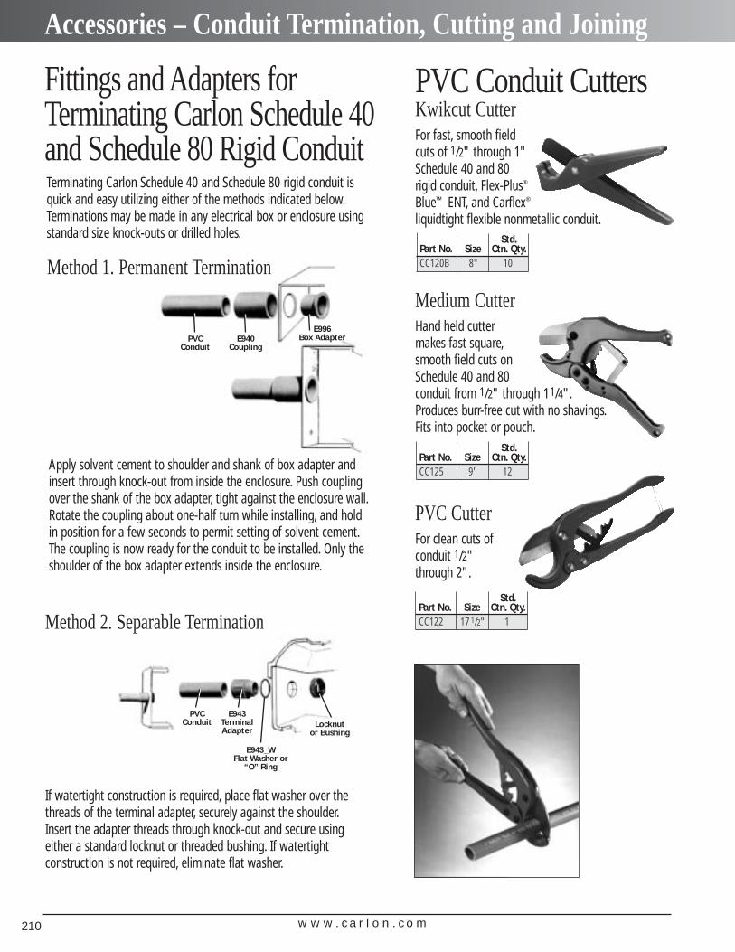
w w w . c a r l o n . c o m210
Accessories – Conduit Termination, Cutting and Joining
Fittings and Adapters forTerminating Carlon Schedule 40and Schedule 80 Rigid ConduitTerminating Carlon Schedule 40 and Schedule 80 rigid conduit isquick and easy utilizing either of the methods indicated below.Terminations may be made in any electrical box or enclosure usingstandard size knock-outs or drilled holes.
Method 2. Separable Termination
PVC Conduit CuttersKwikcut CutterFor fast, smooth field cuts of 1/2" through 1" Schedule 40 and 80 rigid conduit, Flex-Plus®
Blue™ ENT, and Carflex®
liquidtight flexible nonmetallic conduit.
Medium CutterHand held cutter makes fast square,smooth field cuts on Schedule 40 and 80 conduit from 1/2" through 11/4".Produces burr-free cut with no shavings.Fits into pocket or pouch.
PVC CutterFor clean cuts of conduit 1/2" through 2".
PVC Conduit
E940Coupling
E996Box Adapter
PVCConduit
E943TerminalAdapter
E943_WFlat Washer or
“O” Ring
Locknutor Bushing
Apply solvent cement to shoulder and shank of box adapter andinsert through knock-out from inside the enclosure. Push couplingover the shank of the box adapter, tight against the enclosure wall.Rotate the coupling about one-half turn while installing, and holdin position for a few seconds to permit setting of solvent cement.The coupling is now ready for the conduit to be installed. Only theshoulder of the box adapter extends inside the enclosure.
Method 1. Permanent Termination
If watertight construction is required, place flat washer over thethreads of the terminal adapter, securely against the shoulder.Insert the adapter threads through knock-out and secure usingeither a standard locknut or threaded bushing. If watertight construction is not required, eliminate flat washer.
Std.Part No. Size Ctn. Qty.CC120B 8" 10
Std.Part No. Size Ctn. Qty.CC125 9" 12
Std.Part No. Size Ctn. Qty.CC122 17 1/2" 1
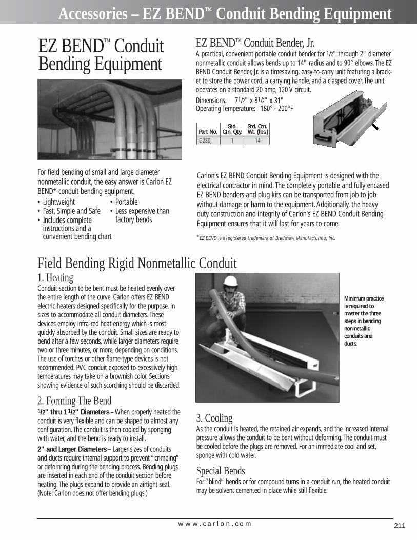
w w w . c a r l o n . c o m 211
Accessories – EZ BEND™ Conduit Bending Equipment
EZ BEND™ ConduitBending Equipment
For field bending of small and large diameter nonmetallic conduit, the easy answer is Carlon EZBEND* conduit bending equipment.• Lightweight • Portable• Fast, Simple and Safe • Less expensive than• Includes complete factory bends
instructions and a convenient bending chart
Field Bending Rigid Nonmetallic Conduit1. HeatingConduit section to be bent must be heated evenly overthe entire length of the curve. Carlon offers EZ BENDelectric heaters designed specifically for the purpose, insizes to accommodate all conduit diameters. Thesedevices employ infra-red heat energy which is mostquickly absorbed by the conduit. Small sizes are ready tobend after a few seconds, while larger diameters requiretwo or three minutes, or more, depending on conditions.The use of torches or other flame-type devices is not recommended. PVC conduit exposed to excessively hightemperatures may take on a brownish color. Sectionsshowing evidence of such scorching should be discarded.
2. Forming The Bend1/2" thru 11/2" Diameters – When properly heated theconduit is very flexible and can be shaped to almost anyconfiguration. The conduit is then cooled by spongingwith water, and the bend is ready to install.2" and Larger Diameters – Larger sizes of conduitsand ducts require internal support to prevent “crimping”or deforming during the bending process. Bending plugsare inserted in each end of the conduit section beforeheating. The plugs expand to provide an airtight seal.(Note: Carlon does not offer bending plugs.)
Minimum practiceis required tomaster the threesteps in bendingnonmetallic conduits andducts.
EZ BEND™ Conduit Bender, Jr.A practical, convenient portable conduit bender for 1/2" through 2" diameternonmetallic conduit allows bends up to 14" radius and to 90° elbows. The EZBEND Conduit Bender, Jr. is a timesaving, easy-to-carry unit featuring a brack-et to store the power cord, a carrying handle, and a clasped cover. The unitoperates on a standard 20 amp, 120 V circuit.Dimensions: 71/2" x 81/2" x 31"Operating Temperature: 180° - 200°F
*EZ BEND is a registered trademark of Bradshaw Manufacturing, Inc.
Std. Std. Ctn.Part No. Ctn. Qty. Wt. (lbs.)G280J 1 14
Carlon’s EZ BEND Conduit Bending Equipment is designed with theelectrical contractor in mind. The completely portable and fully encasedEZ BEND benders and plug kits can be transported from job to job without damage or harm to the equipment. Additionally, the heavyduty construction and integrity of Carlon’s EZ BEND Conduit BendingEquipment ensures that it will last for years to come.
3. CoolingAs the conduit is heated, the retained air expands, and the increased internalpressure allows the conduit to be bent without deforming. The conduit mustbe cooled before the plugs are removed. For an immediate cool and set,sponge with cold water.
Special BendsFor “blind” bends or for compound turns in a conduit run, the heated conduitmay be solvent cemented in place while still flexible.
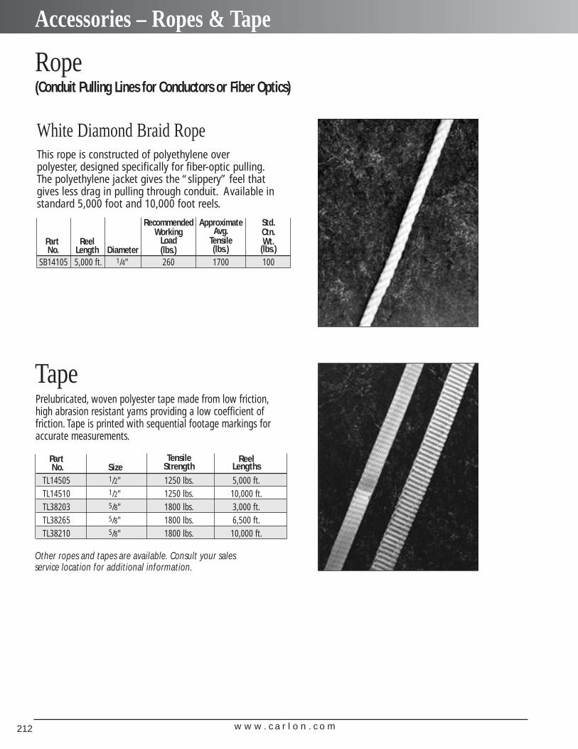
w w w . c a r l o n . c o m212
Accessories – Ropes & Tape
Rope(Conduit Pulling Lines for Conductors or Fiber Optics)
TapePrelubricated, woven polyester tape made from low friction,high abrasion resistant yarns providing a low coefficient of friction. Tape is printed with sequential footage markings foraccurate measurements.
Part Tensile ReelNo. Size Strength Lengths
TL14505 1/2" 1250 lbs. 5,000 ft.TL14510 1/2" 1250 lbs. 10,000 ft.TL38203 5/8" 1800 lbs. 3,000 ft.TL38265 5/8" 1800 lbs. 6,500 ft.TL38210 5/8" 1800 lbs. 10,000 ft.
This rope is constructed of polyethylene over polyester, designed specifically for fiber-optic pulling.The polyethylene jacket gives the “slippery” feel thatgives less drag in pulling through conduit. Available in standard 5,000 foot and 10,000 foot reels.
White Diamond Braid Rope
Recommended Approximate Std.Working Avg. Ctn.
Part Reel Load Tensile Wt.No. Length Diameter (lbs.) (lbs.) (lbs.)
SB14105 5,000 ft. 1/4" 260 1700 100
Other ropes and tapes are available. Consult your sales service location for additional information.
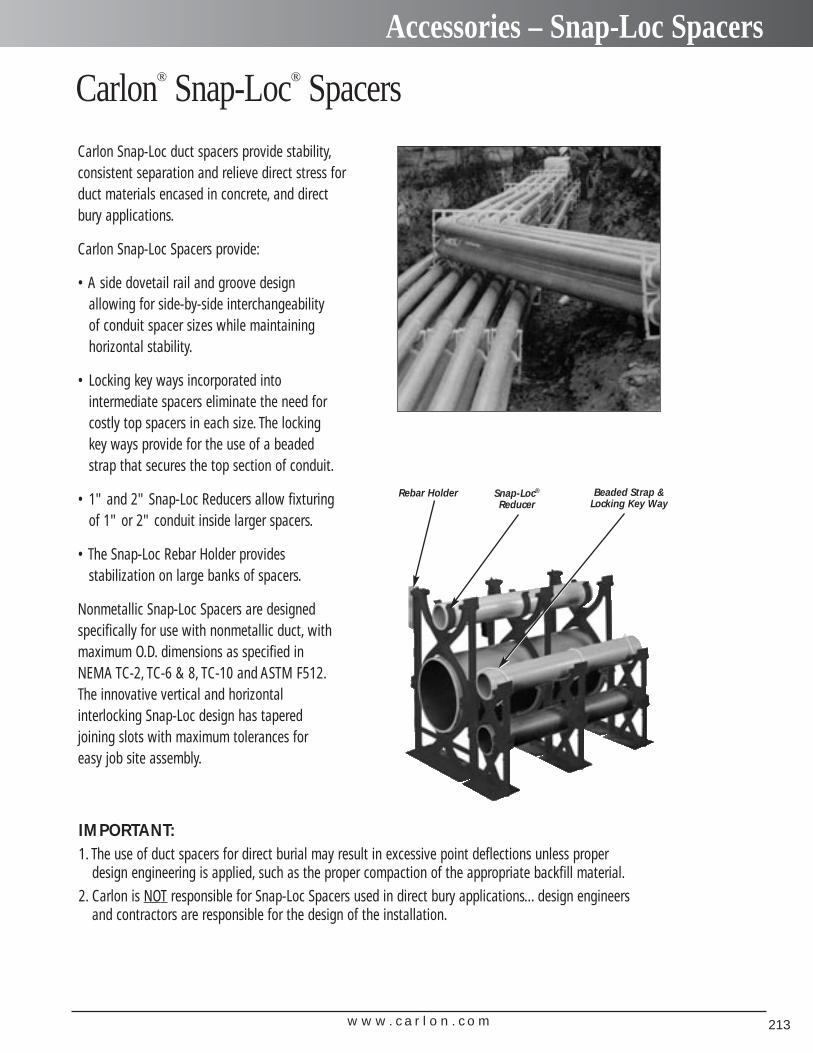
w w w . c a r l o n . c o m 213
Accessories – Snap-Loc Spacers
Carlon Snap-Loc duct spacers provide stability,consistent separation and relieve direct stress forduct materials encased in concrete, and directbury applications.
Carlon Snap-Loc Spacers provide:
• A side dovetail rail and groove design allowing for side-by-side interchangeability of conduit spacer sizes while maintaining horizontal stability.
• Locking key ways incorporated into intermediate spacers eliminate the need forcostly top spacers in each size. The locking key ways provide for the use of a beaded strap that secures the top section of conduit.
• 1" and 2" Snap-Loc Reducers allow fixturing of 1" or 2" conduit inside larger spacers.
• The Snap-Loc Rebar Holder provides stabilization on large banks of spacers.
Nonmetallic Snap-Loc Spacers are designed specifically for use with nonmetallic duct, with maximum O.D. dimensions as specified in NEMA TC-2, TC-6 & 8, TC-10 and ASTM F512.The innovative vertical and horizontal interlocking Snap-Loc design has tapered joining slots with maximum tolerances for easy job site assembly.
Carlon® Snap-Loc® Spacers
Rebar Holder Snap-Loc®
ReducerBeaded Strap &
Locking Key Way
IMPORTANT:1. The use of duct spacers for direct burial may result in excessive point deflections unless proper
design engineering is applied, such as the proper compaction of the appropriate backfill material.2. Carlon is NOT responsible for Snap-Loc Spacers used in direct bury applications... design engineers
and contractors are responsible for the design of the installation.
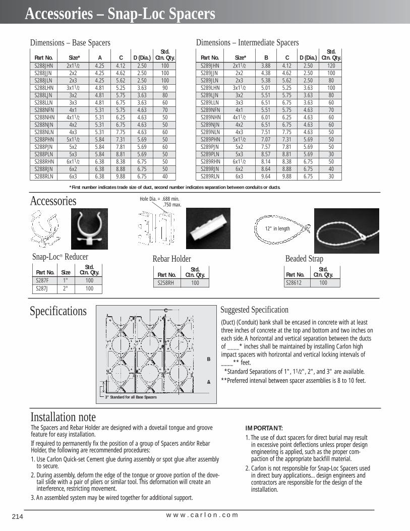
w w w . c a r l o n . c o m214
Accessories – Snap-Loc Spacers
Specifications
Dimensions – Base SpacersStd.
Part No. Size* A C D (Dia.) Ctn. Qty.S288JHN 2x11/2 4.25 4.12 2.50 100S288JJN 2x2 4.25 4.62 2.50 100S288JLN 2x3 4.25 5.62 2.50 100S288LHN 3x11/2 4.81 5.25 3.63 90S288LJN 3x2 4.81 5.75 3.63 80S288LLN 3x3 4.81 6.75 3.63 60S288NFN 4x1 5.31 5.75 4.63 70S288NHN 4x11/2 5.31 6.25 4.63 50S288NJN 4x2 5.31 6.75 4.63 50S288NLN 4x3 5.31 7.75 4.63 60S288PHN 5x11/2 5.84 7.31 5.69 50S288PJN 5x2 5.84 7.81 5.69 60S288PLN 5x3 5.84 8.81 5.69 50S288RHN 6x11/2 6.38 8.38 6.75 50S288RJN 6x2 6.38 8.88 6.75 50S288RLN 6x3 6.38 9.88 6.75 40
Dimensions – Intermediate SpacersStd.
Part No. Size* B C D (Dia.) Ctn. Qty.S289JHN 2x11/2 3.88 4.12 2.50 120S289JJN 2x2 4.38 4.62 2.50 100S289JLN 2x3 5.38 5.62 2.50 80S289LHN 3x11/2 5.01 5.25 3.63 100S289LJN 3x2 5.51 5.75 3.63 80S289LLN 3x3 6.51 6.75 3.63 60S289NFN 4x1 5.51 5.75 4.63 70S289NHN 4x11/2 6.01 6.25 4.63 60S289NJN 4x2 6.51 6.75 4.63 60S289NLN 4x3 7.51 7.75 4.63 50S289PHN 5x11/2 7.07 7.31 5.69 50S289PJN 5x2 7.57 7.81 5.69 50S289PLN 5x3 8.57 8.81 5.69 30S289RHN 6x11/2 8.14 8.38 6.75 50S289RJN 6x2 8.64 8.88 6.75 40S289RLN 6x3 9.64 9.88 6.75 30
B
C
A
Suggested Specification(Duct) (Conduit) bank shall be encased in concrete with at leastthree inches of concrete at the top and bottom and two inches oneach side. A horizontal and vertical separation between the ductsof ____* inches shall be maintained by installing Carlon highimpact spacers with horizontal and vertical locking intervals of____** feet.
*Standard Separations of 1", 11/2", 2", and 3" are available.**Preferred interval between spacer assemblies is 8 to 10 feet.
3" Standard for all Base Spacers
*First number indicates trade size of duct, second number indicates separation between conduits or ducts.
Accessories
Std.Part No. Size Ctn. Qty.S287F 1" 100S287J 2" 100
The Spacers and Rebar Holder are designed with a dovetail tongue and groovefeature for easy installation.If required to permanently fix the position of a group of Spacers and/or RebarHolder, the following are recommended procedures:1. Use Carlon Quick-set Cement glue during assembly or spot glue after assembly
to secure.2. During assembly, deform the edge of the tongue or groove portion of the dove-
tail slide with a pair of pliers or similar tool. This deformation will create aninterference, restricting movement.
3. An assembled system may be wired together for additional support.
Installation note
Snap-Loc® ReducerStd.
Part No. Ctn. Qty.S258RH 100
Rebar HolderStd.
Part No. Ctn. Qty.S28612 100
Beaded Strap
12" in length
Hole Dia. = .688 min..750 max.
IMPORTANT:1. The use of duct spacers for direct burial may result
in excessive point deflections unless proper designengineering is applied, such as the proper com-paction of the appropriate backfill material.
2. Carlon is not responsible for Snap-Loc Spacers usedin direct bury applications... design engineers andcontractors are responsible for the design of theinstallation.
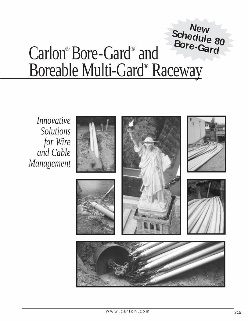
w w w . c a r l o n . c o m 215
InnovativeSolutions for Wire
and CableManagement
New Schedule 80 Bore-GardCarlon® Bore-Gard® and Boreable Multi-Gard® Raceway
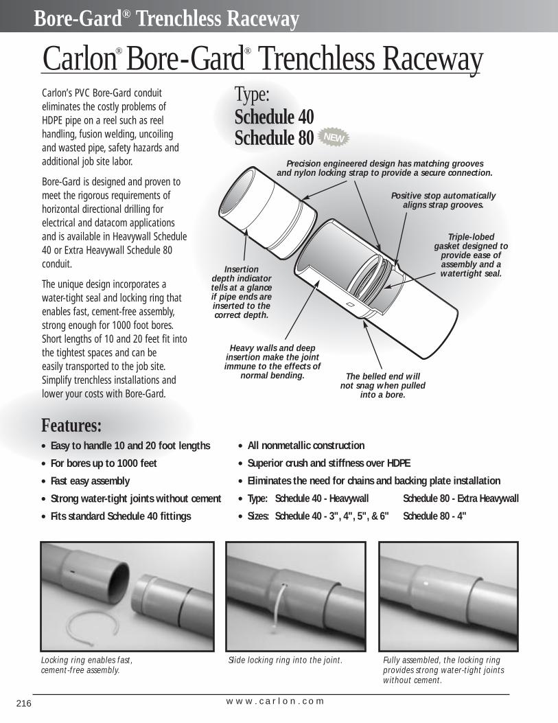
w w w . c a r l o n . c o m216
Bore-Gard® Trenchless Raceway
Locking ring enables fast,cement-free assembly.
Slide locking ring into the joint.
Carlon’s PVC Bore-Gard conduit eliminates the costly problems ofHDPE pipe on a reel such as reel handling, fusion welding, uncoilingand wasted pipe, safety hazards andadditional job site labor.
Bore-Gard is designed and proven tomeet the rigorous requirements ofhorizontal directional drilling for electrical and datacom applicationsand is available in Heavywall Schedule40 or Extra Heavywall Schedule 80conduit.
The unique design incorporates awater-tight seal and locking ring thatenables fast, cement-free assembly,strong enough for 1000 foot bores.Short lengths of 10 and 20 feet fit intothe tightest spaces and can be easily transported to the job site.Simplify trenchless installations andlower your costs with Bore-Gard.
Features:• Easy to handle 10 and 20 foot lengths
• For bores up to 1000 feet
• Fast easy assembly
• Strong water-tight joints without cement
• Fits standard Schedule 40 fittings
Fully assembled, the locking ringprovides strong water-tight jointswithout cement.
Carlon® Bore-Gard® Trenchless Raceway
Insertion depth indicator tells at a glance if pipe ends areinserted to the correct depth.
The belled end will not snag when pulled
into a bore.
Heavy walls and deep insertion make the joint immune to the effects of
normal bending.
Precision engineered design has matching grooves and nylon locking strap to provide a secure connection.
Triple-lobed gasket designed to
provide ease of assembly and a watertight seal.
Positive stop automatically aligns strap grooves.
• All nonmetallic construction
• Superior crush and stiffness over HDPE
• Eliminates the need for chains and backing plate installation
• Type: Schedule 40 - Heavywall Schedule 80 - Extra Heavywall
• Sizes: Schedule 40 - 3", 4", 5", & 6" Schedule 80 - 4"
Type:Schedule 40 Schedule 80 NEW
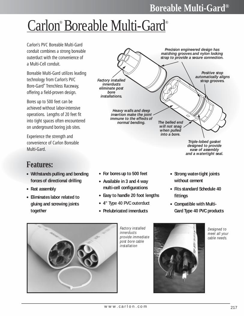
w w w . c a r l o n . c o m 217
Boreable Multi-Gard®
Carlon’s PVC Boreable Multi-Gardconduit combines a strong boreableouterduct with the convenience of a Multi-Cell conduit.
Boreable Multi-Gard utilizes leadingtechnology from Carlon’s PVC Bore-Gard® Trenchless Raceway,offering a field-proven design.
Bores up to 500 feet can beachieved without labor-intensiveoperations. Lengths of 20 feet fitinto tight spaces often encounteredon underground boring job sites.
Experience the strength and convenience of Carlon Boreable Multi-Gard.
The belled endwill not snagwhen pulledinto a bore.
Heavy walls and deep insertion make the joint immune to the effects of
normal bending.
Precision engineered design has matching grooves and nylon lockingstrap to provide a secure connection.
Triple-lobed gasketdesigned to provide
ease of assembly and a watertight seal.
Positive stop automatically aligns
strap grooves.Factory installedinnerducts
eliminate postbore
installations.
Factory installedinnerducts provide immediatepost bore cableinstallation
Carlon® Boreable Multi-Gard®
Features:• Withstands pulling and bending
forces of directional drilling
• Fast assembly
• Eliminates labor related to gluing and screwing jointstogether
• For bores up to 500 feet
• Available in 3 and 4 way multi-cell configurations
• Easy to handle 20 foot lengths
• 4" Type 40 PVC outerduct
• Prelubricated innerducts
Designed tomeet all yourcable needs.
• Strong water-tight jointswithout cement
• Fits standard Schedule 40 fittings
• Compatible with Multi-Gard Type 40 PVC products
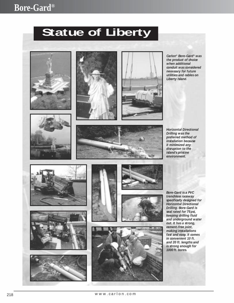
w w w . c a r l o n . c o m218
Bore-Gard®
Statue of Liberty
Carlon® Bore-Gard® wasthe product of choicewhen additional conduit was considerednecessary for futureutilities and cables onLiberty Island.
Horizontal DirectionalDrilling was the preferred method ofinstallation because it minimized any disruption to theisland’s pristine environment.
Bore-Gard is a PVCtrenchless racewayspecifically designed forHorizontal DirectionalDrilling. Bore-Gard isseal rated for 75psi,keeping drilling fluidand underground waterout. It has a strong,cement-free joint, making installationsfast and easy. It comesin convenient 10 ft. and 20 ft. lengths andis strong enough for1000 ft. bores.
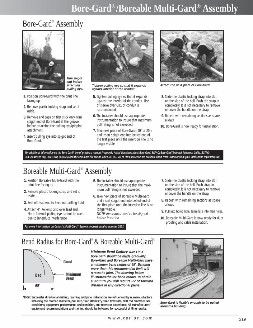
w w w . c a r l o n . c o m 219
Bore-Gard®/Boreable Multi-Gard® Assembly
Minimum Bend Radius: Turns in a bore path should be made gradually.Bore-Gard and Boreable Multi-Gard havea minimum bend radius of 65'. Bendingmore than this recommended limit willstress the joint. The drawing below illustrates the 65' bend radius. To obtaina 90° turn you will require 65' of forwarddistance in any directional plane.
Note: Successful directional drilling, reaming and pipe installation are influenced by numerous factorsincluding the reamed diameter, pull rate, fluid chemistry, fluid flow rate, drill rod diameter, soilconditions, equipment performance and condition, and operator experience. All manufacturers’equipment recommendations and training should be followed for successful drilling results.
Bore-Gard® Assembly
Boreable Multi-Gard® Assembly
Bend Radius for Bore-Gard® & Boreable Multi-Gard®
1. Position Boreable Multi-Gard with theprint line facing up.
2. Remove plastic locking strap and set itaside.
3. Seal off lead end to keep out drilling fluid.
4. Attach 4" Kellems Grip over lead end.Note: Internal pulling eye cannot be useddue to innerduct interference.
5. The installer should use appropriateinstrumentation to insure that the maxi-mum pull rating is not exceeded.
6. Take next piece of Boreable Multi-Gardand insert spigot end into belled end ofthe first piece until the insertion line is nolonger visible.NOTE: Innerducts need to be alignedbefore insertion
7. Slide the plastic locking strap into slot on the side of the bell. Push strap in completely. It is not necessary to remove or cover the handle on the strap.
8. Repeat with remaining sections as spaceallows.
9. Pull into bored hole. Terminate into man holes.
10. Boreable Multi-Gard is now ready for ductproofing and cable installation.
For more information on Carlon’s Multi-Gard® System, request catalog number 2B21.
8. Slide the plastic locking strap into slot on the side of the bell. Push the strap incompletely. It is not necessary to removeor cover the handle on the strap.
9. Repeat with remaining sections as spaceallows.
10. Bore-Gard is now ready for installation.
1. Position Bore-Gard with the print line facing up.
2. Remove plastic locking strap and set itaside.
3. Remove end caps on first stick only, trimspigot end of Bore-Gard at the groovebefore attaching the pulling eye/grippingattachment.
4. Insert pulling eye into spigot end of Bore-Gard.
5. Tighten pulling eye so that it expandsagainst the interior of the conduit. Use of sleeve over O.D. of conduit is recommended.
6. The installer should use appropriate instrumentation to insure that maximumpull rating is not exceeded.
7. Take next piece of Bore-Gard (10' or 20') and insert spigot end into belled end ofthe first piece until the insertion line is nolonger visible.
For additional information on the Bore-Gard® line of products, request Frequently Asked Questions about Bore-Gard, BGFAQ; Bore-Gard Technical Reference Guide, BGTRG; Ten Reasons to Buy Bore-Gard, BG10REA and the Bore-Gard six minute Video, BGVID. All of these materials are available direct from Carlon or from your local Carlon representative.
Tighten pulling eye so that it expandsagainst interior of the conduit.
Trim spigotend beforeattachingpulling eye.
Bore-Gard is flexible enough to be pulledaround a building.
Attach the next piece of Bore-Gard.
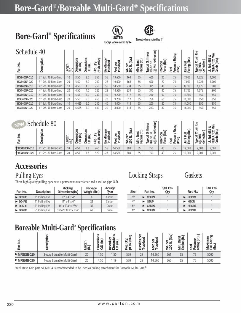
w w w . c a r l o n . c o m220
Bore-Gard®/Boreable Multi-Gard® Specifications
BG340SP-010 3" Sch. 40 Bore-Gard 10 3.50 3.0 350 56 19,600 164 65 600 20 75 7,000 1,225 1,000BG340SP-020 3" Sch. 40 Bore-Gard 20 3.50 3.0 700 28 19,600 164 65 600 20 75 7,000 1,225 1,000BG440SP-010 4" Sch. 40 Bore-Gard 10 4.50 4.0 260 56 14,560 234 65 375 40 75 8,700 1,075 900BG440SP-020 4" Sch. 40 Bore-Gard 20 4.50 4.0 520 28 14,560 234 65 375 40 75 8,700 1,075 900BG540SP-010 5" Sch. 40 Bore-Gard 10 5.56 5.0 230 40 9,200 317 65 250 60 75 11,300 950 850BG540SP-020 5" Sch. 40 Bore-Gard 20 5.56 5.0 460 20 9,200 317 65 250 60 75 11,300 950 850BG640SP-010 6" Sch. 40 Bore-Gard 10 6.625 6.0 200 40 8,000 418 65 200 80 75 14,000 950 850BG640SP-020 6" Sch. 40 Bore-Gard 20 6.625 6.0 400 20 8,000 418 65 200. 80 75 14,000 950 850
Part
No.
Bore-Gard® SpecificationsDe
scrip
tion
Leng
th(ft
.)
Dim
ensio
nsO.
D.(in
.)
Dim
ensio
nsI.D
.(in
.)
Pkg.
Qty.
(ft./b
undl
e)
Bund
les p
erTr
uckl
oad
Feet
per
Truc
kloa
d
Wt.
per
100
ft.(lb
s.)
Min
.Ben
dRa
dius
(ft.)
Inse
rtio
nFo
rce
(lbs.)
Typi
cal S
tiffn
ess
lbs./
in./i
n.(@
5%
def
lect
ion)
Join
t Pul
lRa
ting
(lbs.)
Seal
Pr
essu
re R
ating
(P.S.I
.)
Typi
cal C
rush
lbs.
(@ 3
0%
defle
ctio
n)
UL S
td.6
51 &
NEM
A TC
2 M
in.
Crus
h (lb
s.)
MFSS3B-020 3-way Boreable Multi-Gard 20 4.50 1.50 520 28 14,560 561 65 75 5000
MFSS4B-020 4-way Boreable Multi-Gard 20 4.50 1.19 520 28 14,560 565 65 75 5000
Part
No.
Steel Mesh Grip part no. MAG4 is recommended to be used as pulling attachment for Boreable Multi-Gard®.
Desc
riptio
n
Leng
th(ft
.)
Dim
ensi
ons
O.D.
(in.)
Inne
rduc
tDi
men
sion
sI.D
.(in
.)
Pkg.
Qty.
(ft./b
undl
e)
Bund
les
per
Truc
kloa
d
Feet
per
Truc
kloa
d
Wt.
per
100
ft.(
lbs.)
Min
.Ben
dRa
dius
(ft.)
Max
imum
Pull
Ratin
g(lb
s.)
Seal
Pr
essu
reRa
ting
(P.S.I
.)
Except where noted byExcept where noted by †
�
BG3PE 3" Pulling Eye 10"x 4"x 4" 8 CartonBG4PE 4" Pulling Eye 17"x 6"x 6" 26 CartonBG5PE 5" Pulling Eye 16"x 73/4"x 73/4" 37 CrateBG6PE 6" Pulling Eye 191/2"x 81/4"x 81/4" 63 Crate
Part No.
Pulling Eyes These high-quality pulling eyes have a permanent outer sleeve and a seal on pipe O.D.
DescriptionPackage
Dimensions (in.)Package
Weight (lbs.)Package
Type
�
�
�
�
�
�
Accessories
Schedule 40
BG480SP-010 4" Sch. 80 Bore-Gard 10 4.50 3.8 260 56 14,560 308 65 750 40 75 12,000 2,000 2,000
BG480SP-020 4" Sch. 80 Bore-Gard 20 4.50 3.8 520 28 14,560 308 65 750 40 75 12,000 2,000 2,000
Part
No.
Desc
riptio
n
Leng
th(ft
.)
Dim
ensio
nsO.
D.(in
.)
Dim
ensio
nsI.D
.(in
.)
Pkg.
Qty.
(ft./b
undl
e)
Bund
les p
erTr
uckl
oad
Feet
per
Truc
kloa
d
Wt.
per
100
ft.(lb
s.)
Min
.Ben
dRa
dius
(ft.)
Inse
rtio
nFo
rce
(lbs.)
Typi
cal S
tiffn
ess
lbs./
in./i
n.(@
5%
def
lect
ion)
Join
t Pul
lRa
ting
(lbs.)
Seal
Pr
essu
re R
ating
(P.S.I
.)
Typi
cal C
rush
lbs.
(@ 3
0%
defle
ctio
n)
UL S
td.6
51 &
NEM
A TC
2 M
in.
Crus
h (lb
s.)
Schedule 80
Boreable Multi-Gard® Specifications
3" GSUP3 1 HBOR3 14" GSUP 1 HBOR 15" GSUP5 1 HBOR5 16" GSUP6 1 HBOR6 1
Size Part No.Std. Ctn.
Qty. Part No.Std. Ctn.
Qty.�
�
�
�
�
�
�
�
Locking Straps Gaskets
††
NEW
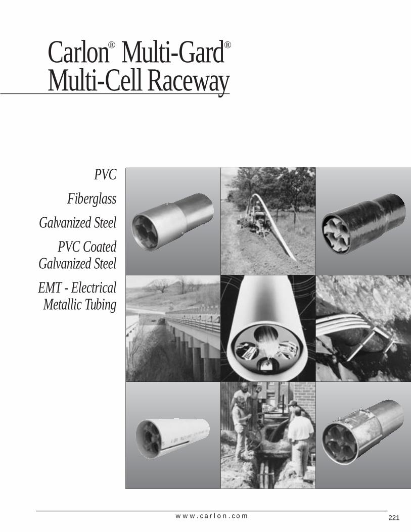
Carlon® Multi-Gard®
Multi-Cell Raceway
PVC
Fiberglass
Galvanized Steel
PVC CoatedGalvanized Steel
EMT - ElectricalMetallic Tubing
w w w . c a r l o n . c o m 221
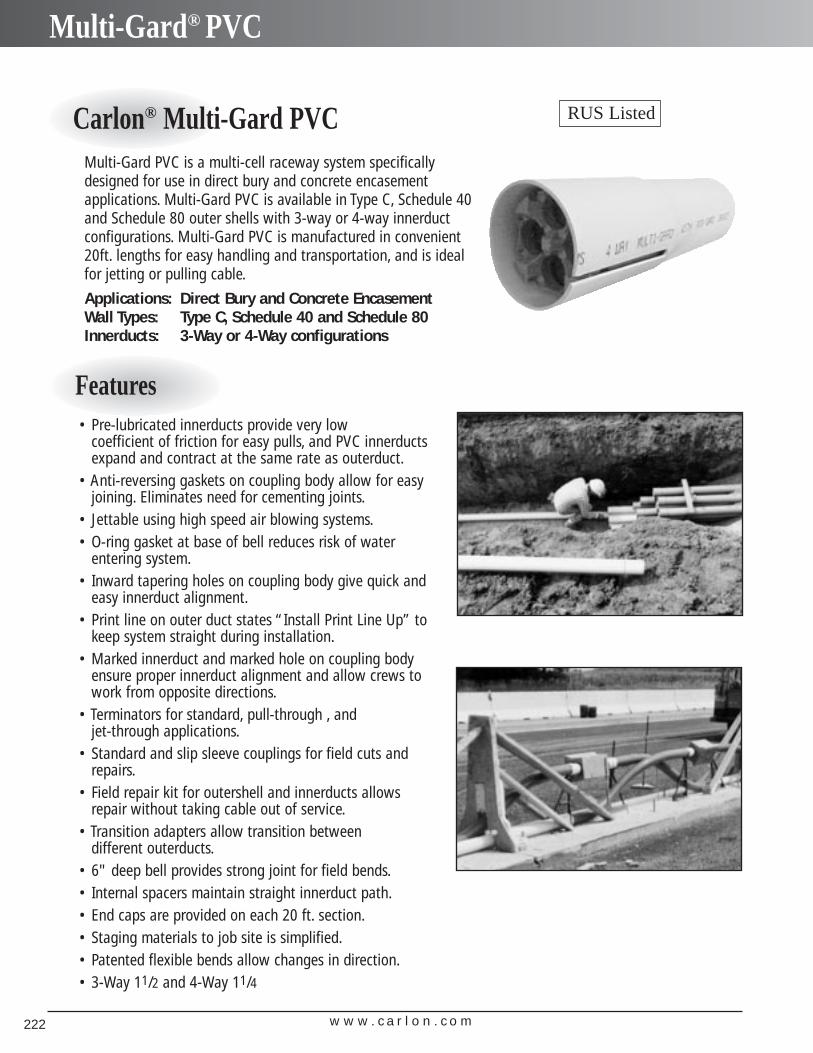
w w w . c a r l o n . c o m222
Multi-Gard® PVC
Carlon® Multi-Gard PVC
Features
Multi-Gard PVC is a multi-cell raceway system specificallydesigned for use in direct bury and concrete encasement applications. Multi-Gard PVC is available in Type C, Schedule 40and Schedule 80 outer shells with 3-way or 4-way innerduct configurations. Multi-Gard PVC is manufactured in convenient20ft. lengths for easy handling and transportation, and is idealfor jetting or pulling cable.
Applications: Direct Bury and Concrete EncasementWall Types: Type C, Schedule 40 and Schedule 80Innerducts: 3-Way or 4-Way configurations
RUS Listed
• Pre-lubricated innerducts provide very low coefficient of friction for easy pulls, and PVC innerductsexpand and contract at the same rate as outerduct.
• Anti-reversing gaskets on coupling body allow for easyjoining. Eliminates need for cementing joints.
• Jettable using high speed air blowing systems.• O-ring gasket at base of bell reduces risk of water
entering system.• Inward tapering holes on coupling body give quick and
easy innerduct alignment.• Print line on outer duct states “Install Print Line Up” to
keep system straight during installation.• Marked innerduct and marked hole on coupling body
ensure proper innerduct alignment and allow crews towork from opposite directions.
• Terminators for standard, pull-through , and jet-through applications.
• Standard and slip sleeve couplings for field cuts andrepairs.
• Field repair kit for outershell and innerducts allowsrepair without taking cable out of service.
• Transition adapters allow transition between different outerducts.
• 6" deep bell provides strong joint for field bends.• Internal spacers maintain straight innerduct path.• End caps are provided on each 20 ft. section.• Staging materials to job site is simplified.• Patented flexible bends allow changes in direction.• 3-Way 11/2 and 4-Way 11/4
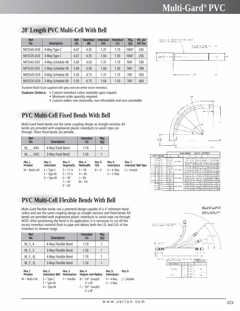
w w w . c a r l o n . c o m 223
Multi-Gard® PVC
20' Length PVC Multi-Cell With BellPart Bell Outerduct Innerduct Innerduct Pkg. Wt. perNo. Description (A) (B) O.D. I.D. Qty. 100 lbs.
MXSS4S-020 4-Way Type C 4.67 4.35 1.31 1.19 1060' 245
MXSS3S-020 3-Way Type C 4.67 4.35 1.66 1.50 1060' 256
MFSS4S-020 4-Way Schedule 40 5.00 4.50 1.31 1.19 960' 338
MFSS3S-020 3-Way Schedule 40 5.00 4.50 1.66 1.50 960' 348
MDSS4S-020 4-Way Schedule 80 5.50 4.75 1.31 1.19 760' 450
MDSS3S-020 3-Way Schedule 80 5.50 4.75 1.66 1.50 760' 460
Standard Multi-Gard supplied with grey and one white tracer innerduct.
Custom Orders: * Custom innerduct colors available upon request* Minimum order quantity required* Custom orders non-returnable, non-refundable and non-cancelable
PVC Multi-Cell Fixed Bends With Bell
Part Innerduct Pkg.No. Description I.D. Qty.
M_ _ _ N4S 4-Way Fixed Bend 1.19 1
M_ _ _ N3S 3-Way Fixed Bend 1.50 1
Pos. 1 Pos. 2 Pos. 3 Pos. 4 Pos. 5 Pos. 6 Pos. 7Product Outerduct Degree(A) Radius(R) O.D. Innerducts Innerduct Wall Type
M = Multi-Cell X = Type C 3 = 111/4 F = 3ft. N = 4" 4 = 4 -Way S = SmoothF = Type 40 5 = 221/2 H = 4ft. 3 = 3-WayD = Type 80 6 = 30˚ J = 6ft.
7 = 45˚ M = 9ft.9 = 90˚
Multi-Gard fixed bends use the same coupling design as straight sections. Allbends are provided with engineered plastic innerducts to avoid rope cut-through. These fixed bends are jettable.
PVC Multi-Cell Flexible Bends With Bell
Part Innerduct Pkg.No. Description I.D. Qty.
M_F_4 4-Way Flexible Bend 1.19 1
M_F_3 3-Way Flexible Bend 1.50 1
M_F_4J 4-Way Flexible Bend 1.19 1
M_F_3J 3-Way Flexible Bend 1.50 1
Pos. 1 Pos. 2 Pos. 3 Pos. 4 Pos. 5 Pos. 6Product Outerduct Bell Description Degree and Radius Innerducts
M = Multi-Cell X = Type C F = Flexible B = 126" (Length) 4 = 4-Way J = JettableF = Type 40 4' x 90˚ 3 = 3-WayD = Type 80 C = 192" (Length)
6' x 90˚
Multi-Gard flexible bends use a patented design capable of a 4' minimum bendradius and use the same coupling design as straight sections and fixed bends. Allbends are provided with engineered plastic innerducts to avoid rope cut-through.NOTE: After positioning the bend in its application, it is necessary to cut off theexcess innerduct material flush to pipe and deburr both the I.D. and O.D. of theinnerduct to remove snags.
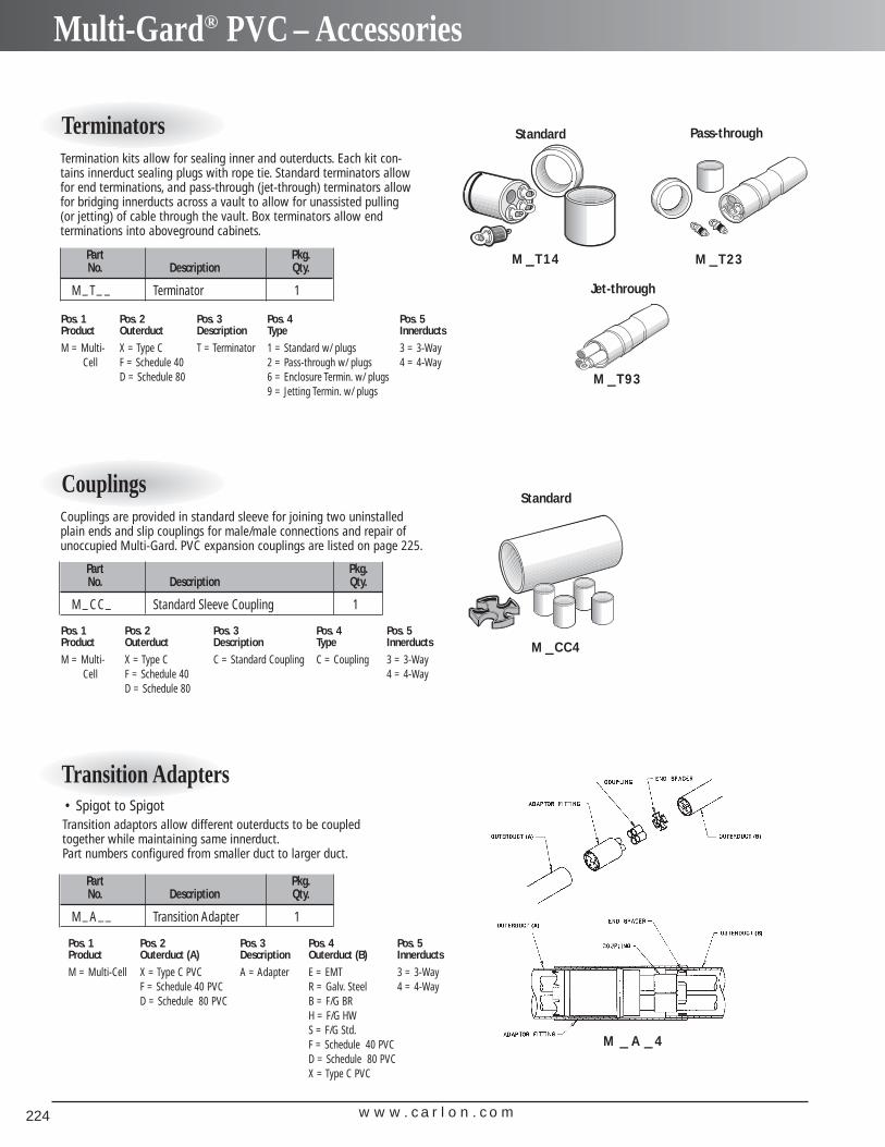
w w w . c a r l o n . c o m224
Multi-Gard® PVC – Accessories
Terminators
Part Pkg.No. Description Qty.
M_T_ _ Terminator 1
Pos. 1 Pos. 2 Pos. 3 Pos. 4 Pos. 5Product Outerduct Description Type Innerducts
M = Multi- X = Type C T = Terminator 1 = Standard w/ plugs 3 = 3-WayCell F = Schedule 40 2 = Pass-through w/ plugs 4 = 4-Way
D = Schedule 80 6 = Enclosure Termin. w/ plugs9 = Jetting Termin. w/ plugs
Termination kits allow for sealing inner and outerducts. Each kit con-tains innerduct sealing plugs with rope tie. Standard terminators allowfor end terminations, and pass-through (jet-through) terminators allowfor bridging innerducts across a vault to allow for unassisted pulling(or jetting) of cable through the vault. Box terminators allow end terminations into aboveground cabinets.
Transition Adapters
Part Pkg.No. Description Qty.
M_A__ Transition Adapter 1
Pos. 1 Pos. 2 Pos. 3 Pos. 4 Pos. 5Product Outerduct (A) Description Outerduct (B) Innerducts
M = Multi-Cell X = Type C PVC A = Adapter E = EMT 3 = 3-WayF = Schedule 40 PVC R = Galv. Steel 4 = 4-WayD = Schedule 80 PVC B = F/G BR
H = F/G HWS = F/G Std.F = Schedule 40 PVCD = Schedule 80 PVCX = Type C PVC
Transition adaptors allow different outerducts to be coupled together while maintaining same innerduct.Part numbers configured from smaller duct to larger duct.
Standard
Standard
Pass-through
M T14– M T23–
M CC4–
M A 4– –
Jet-through
M T93–
Couplings
Part Pkg.No. Description Qty.
M_CC_ Standard Sleeve Coupling 1
Pos. 1 Pos. 2 Pos. 3 Pos. 4 Pos. 5Product Outerduct Description Type Innerducts
M = Multi- X = Type C C = Standard Coupling C = Coupling 3 = 3-WayCell F = Schedule 40 4 = 4-Way
D = Schedule 80
Couplings are provided in standard sleeve for joining two uninstalled plain ends and slip couplings for male/male connections and repair ofunoccupied Multi-Gard. PVC expansion couplings are listed on page 225.
• Spigot to Spigot
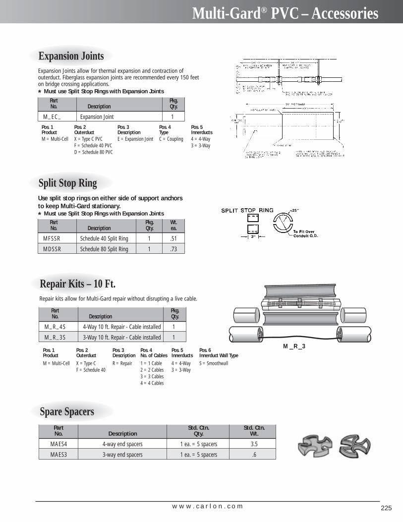
w w w . c a r l o n . c o m 225
Multi-Gard® PVC – Accessories
Repair Kits – 10 Ft.
Part Pkg.No. Description Qty.
M_R_4S 4-Way 10 ft. Repair - Cable installed 1
M_R_3S 3-Way 10 ft. Repair - Cable installed 1
Repair kits allow for Multi-Gard repair without disrupting a live cable.
M R 3– –
Expansion Joints
Part Pkg.No. Description Qty.
M_EC_ Expansion Joint 1
Pos. 1 Pos. 2 Pos. 3 Pos. 4 Pos. 5Product Outerduct Description Type InnerductsM = Multi-Cell X = Type C PVC E = Expansion Joint C = Coupling 4 = 4-Way
F = Schedule 40 PVC 3 = 3-WayD = Schedule 80 PVC
Expansion Joints allow for thermal expansion and contraction of outerduct. Fiberglass expansion joints are recommended every 150 feet on bridge crossing applications.
* Must use Split Stop Rings with Expansion Joints
Split Stop Ring
Part Pkg. Wt.No. Description Qty. ea.
MFSSR Schedule 40 Split Ring 1 .51
MDSSR Schedule 80 Split Ring 1 .73
Use split stop rings on either side of support anchors to keep Multi-Gard stationary.* Must use Split Stop Rings with Expansion Joints
Pos. 1 Pos. 2 Pos. 3 Pos. 4 Pos. 5 Pos. 6Product Outerduct Description No. of Cables Innerducts Innerduct Wall Type
M = Multi-Cell X = Type C R = Repair 1 = 1 Cable 4 = 4-Way S = SmoothwallF = Schedule 40 2 = 2 Cables 3 = 3-Way
3 = 3 Cables4 = 4 Cables
Spare SpacersPart Std. Ctn. Std. Ctn.No. Description Qty. Wt.
MAES4 4-way end spacers 1 ea. = 5 spacers 3.5
MAES3 3-way end spacers 1 ea. = 5 spacers .6
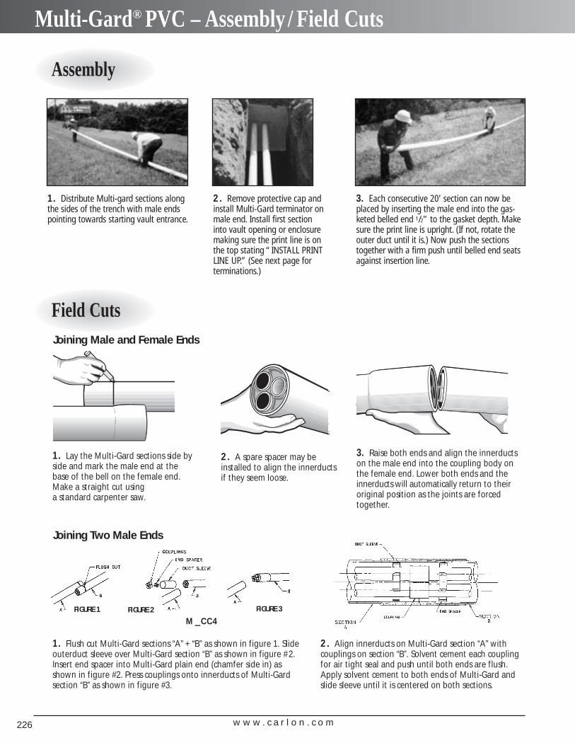
w w w . c a r l o n . c o m226
Multi-Gard® PVC – Assembly / Field Cuts
Assembly
Field Cuts
1. Distribute Multi-gard sections alongthe sides of the trench with male endspointing towards starting vault entrance.
2. Remove protective cap andinstall Multi-Gard terminator onmale end. Install first section into vault opening or enclosure making sure the print line is onthe top stating “INSTALL PRINTLINE UP.” (See next page for terminations.)
2. A spare spacer may beinstalled to align the innerductsif they seem loose.
2. Align innerducts on Multi-Gard section “A” with couplings on section “B”. Solvent cement each couplingfor air tight seal and push until both ends are flush.Apply solvent cement to both ends of Multi-Gard andslide sleeve until it is centered on both sections.
3. Each consecutive 20' section can now beplaced by inserting the male end into the gas-keted belled end 1/2" to the gasket depth. Makesure the print line is upright. (If not, rotate theouter duct until it is.) Now push the sectionstogether with a firm push until belled end seatsagainst insertion line.
3. Raise both ends and align the innerductson the male end into the coupling body onthe female end. Lower both ends and theinnerducts will automatically return to theiroriginal position as the joints are forcedtogether.
Joining Male and Female Ends
Joining Two Male Ends
1. Lay the Multi-Gard sections side byside and mark the male end at thebase of the bell on the female end.Make a straight cut using a standard carpenter saw.
1. Flush cut Multi-Gard sections “A” + “B” as shown in figure 1. Slideouterduct sleeve over Multi-Gard section “B” as shown in figure #2.Insert end spacer into Multi-Gard plain end (chamfer side in) asshown in figure #2. Press couplings onto innerducts of Multi-Gard section “B” as shown in figure #3.
FIGURE 1 FIGURE 2 FIGURE 3
M CC4–
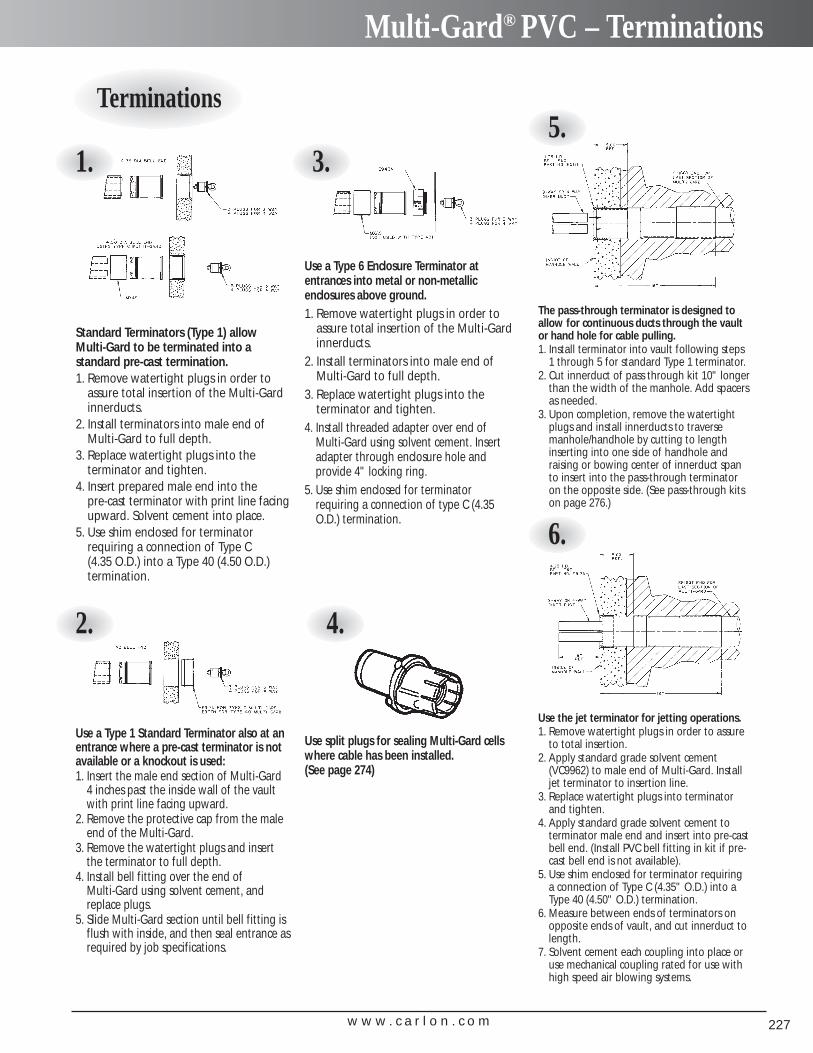
w w w . c a r l o n . c o m 227
Multi-Gard® PVC – Terminations
Standard Terminators (Type 1) allow Multi-Gard to be terminated into a standard pre-cast termination.1. Remove watertight plugs in order to
assure total insertion of the Multi-Gardinnerducts.
2. Install terminators into male end ofMulti-Gard to full depth.
3. Replace watertight plugs into the terminator and tighten.
4. Insert prepared male end into the pre-cast terminator with print line facingupward. Solvent cement into place.
5. Use shim enclosed for terminator requiring a connection of Type C (4.35 O.D.) into a Type 40 (4.50 O.D.) termination.
Use a Type 6 Enclosure Terminator atentrances into metal or non-metallic enclosures above ground.1. Remove watertight plugs in order to
assure total insertion of the Multi-Gardinnerducts.
2. Install terminators into male end ofMulti-Gard to full depth.
3. Replace watertight plugs into the terminator and tighten.
4. Install threaded adapter over end of Multi-Gard using solvent cement. Insertadapter through enclosure hole and provide 4" locking ring.
5. Use shim enclosed for terminator requiring a connection of type C (4.35O.D.) termination.
The pass-through terminator is designed toallow for continuous ducts through the vault or hand hole for cable pulling.1. Install terminator into vault following steps
1 through 5 for standard Type 1 terminator.2. Cut innerduct of pass through kit 10" longer
than the width of the manhole. Add spacersas needed.
3. Upon completion, remove the watertightplugs and install innerducts to traverse manhole/handhole by cutting to lengthinserting into one side of handhole and raising or bowing center of innerduct spanto insert into the pass-through terminator on the opposite side. (See pass-through kitson page 276.)
Use a Type 1 Standard Terminator also at anentrance where a pre-cast terminator is notavailable or a knockout is used:1. Insert the male end section of Multi-Gard
4 inches past the inside wall of the vaultwith print line facing upward.
2. Remove the protective cap from the maleend of the Multi-Gard.
3. Remove the watertight plugs and insertthe terminator to full depth.
4. Install bell fitting over the end of Multi-Gard using solvent cement, andreplace plugs.
5. Slide Multi-Gard section until bell fitting isflush with inside, and then seal entrance asrequired by job specifications.
Use the jet terminator for jetting operations.1. Remove watertight plugs in order to assure
to total insertion.2. Apply standard grade solvent cement
(VC9962) to male end of Multi-Gard. Installjet terminator to insertion line.
3. Replace watertight plugs into terminator and tighten.
4. Apply standard grade solvent cement to terminator male end and insert into pre-castbell end. (Install PVC bell fitting in kit if pre-cast bell end is not available).
5. Use shim enclosed for terminator requiring a connection of Type C (4.35" O.D.) into aType 40 (4.50" O.D.) termination.
6. Measure between ends of terminators onopposite ends of vault, and cut innerduct tolength.
7. Solvent cement each coupling into place oruse mechanical coupling rated for use withhigh speed air blowing systems.
Use split plugs for sealing Multi-Gard cellswhere cable has been installed. (See page 274)
Terminations
1. 3.5.
4.2.
6.
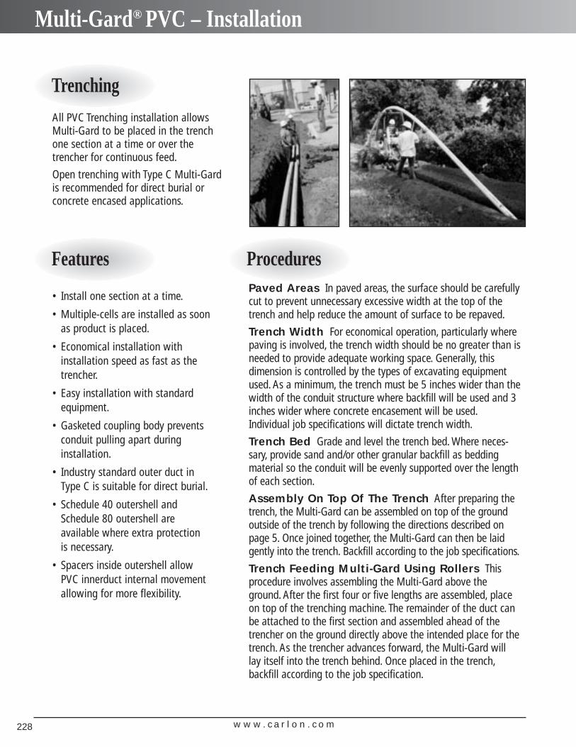
w w w . c a r l o n . c o m228
Multi-Gard® PVC – Installation
All PVC Trenching installation allowsMulti-Gard to be placed in the trenchone section at a time or over thetrencher for continuous feed.
Open trenching with Type C Multi-Gardis recommended for direct burial orconcrete encased applications.
• Install one section at a time.
• Multiple-cells are installed as soonas product is placed.
• Economical installation with installation speed as fast as thetrencher.
• Easy installation with standardequipment.
• Gasketed coupling body prevents conduit pulling apart during installation.
• Industry standard outer duct inType C is suitable for direct burial.
• Schedule 40 outershell andSchedule 80 outershell are available where extra protection is necessary.
• Spacers inside outershell allow PVC innerduct internal movement allowing for more flexibility.
Paved Areas In paved areas, the surface should be carefullycut to prevent unnecessary excessive width at the top of thetrench and help reduce the amount of surface to be repaved.
Trench Width For economical operation, particularly wherepaving is involved, the trench width should be no greater than isneeded to provide adequate working space. Generally, thisdimension is controlled by the types of excavating equipmentused. As a minimum, the trench must be 5 inches wider than thewidth of the conduit structure where backfill will be used and 3inches wider where concrete encasement will be used.Individual job specifications will dictate trench width.
Trench Bed Grade and level the trench bed. Where neces-sary, provide sand and/or other granular backfill as beddingmaterial so the conduit will be evenly supported over the lengthof each section.
Assembly On Top Of The Trench After preparing thetrench, the Multi-Gard can be assembled on top of the groundoutside of the trench by following the directions described onpage 5. Once joined together, the Multi-Gard can then be laidgently into the trench. Backfill according to the job specifications.
Trench Feeding Multi-Gard Using Rollers Thisprocedure involves assembling the Multi-Gard above theground. After the first four or five lengths are assembled, placeon top of the trenching machine. The remainder of the duct canbe attached to the first section and assembled ahead of thetrencher on the ground directly above the intended place for thetrench. As the trencher advances forward, the Multi-Gard willlay itself into the trench behind. Once placed in the trench,backfill according to the job specification.
Trenching
Features Procedures
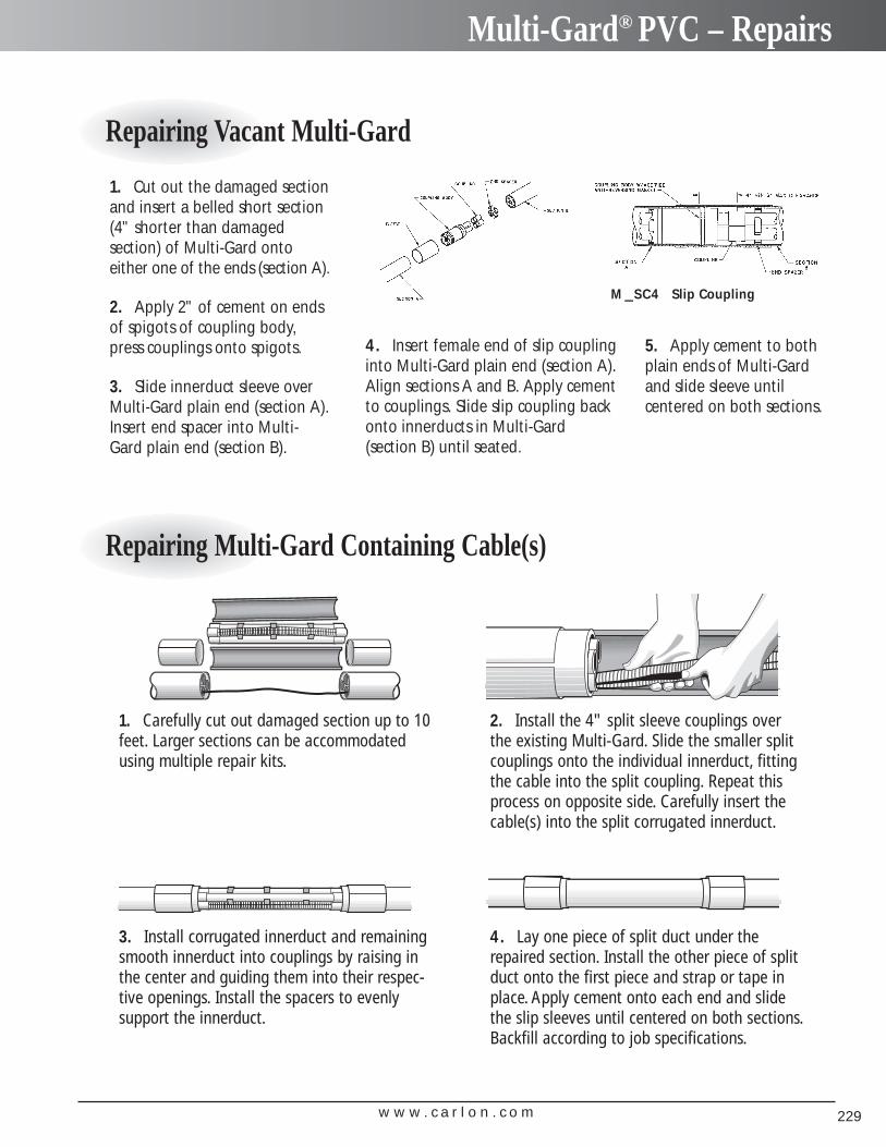
w w w . c a r l o n . c o m 229
Multi-Gard® PVC – Repairs
Repairing Vacant Multi-Gard
Repairing Multi-Gard Containing Cable(s)
1. Cut out the damaged sectionand insert a belled short section(4" shorter than damaged section) of Multi-Gard ontoeither one of the ends (section A).
2. Apply 2" of cement on ends of spigots of coupling body, press couplings onto spigots.
3. Slide innerduct sleeve over Multi-Gard plain end (section A).Insert end spacer into Multi-Gard plain end (section B).
1. Carefully cut out damaged section up to 10feet. Larger sections can be accommodatedusing multiple repair kits.
3. Install corrugated innerduct and remainingsmooth innerduct into couplings by raising inthe center and guiding them into their respec-tive openings. Install the spacers to evenly support the innerduct.
4. Lay one piece of split duct under therepaired section. Install the other piece of splitduct onto the first piece and strap or tape inplace. Apply cement onto each end and slidethe slip sleeves until centered on both sections.Backfill according to job specifications.
2. Install the 4" split sleeve couplings overthe existing Multi-Gard. Slide the smaller splitcouplings onto the individual innerduct, fittingthe cable into the split coupling. Repeat thisprocess on opposite side. Carefully insert thecable(s) into the split corrugated innerduct.
4. Insert female end of slip couplinginto Multi-Gard plain end (section A).Align sections A and B. Apply cementto couplings. Slide slip coupling backonto innerducts in Multi-Gard (section B) until seated.
5. Apply cement to bothplain ends of Multi-Gardand slide sleeve until centered on both sections.
M SC4– Slip Coupling
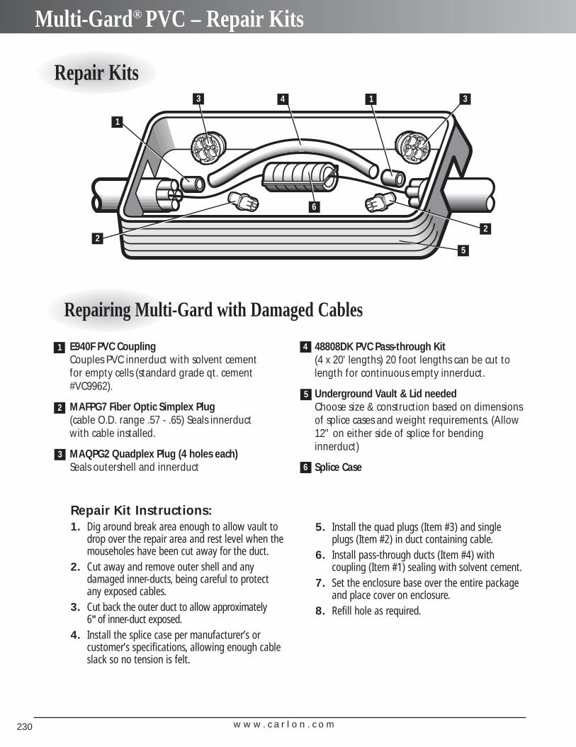
w w w . c a r l o n . c o m230
Multi-Gard® PVC – Repair Kits
Repair Kits
Repairing Multi-Gard with Damaged Cables
E940F PVC Coupling Couples PVC innerduct with solvent cementfor empty cells (standard grade qt. cement#VC9962).
MAFPG7 Fiber Optic Simplex Plug (cable O.D. range .57 - .65) Seals innerductwith cable installed.
MAQPG2 Quadplex Plug (4 holes each) Seals outershell and innerduct
1
2
3
4
5
Repair Kit Instructions:1. Dig around break area enough to allow vault to
drop over the repair area and rest level when themouseholes have been cut away for the duct.
2. Cut away and remove outer shell and any damaged inner-ducts, being careful to protect any exposed cables.
3. Cut back the outer duct to allow approximately 6"of inner-duct exposed.
4. Install the splice case per manufacturer’s or customer’s specifications, allowing enough cableslack so no tension is felt.
2
1
3 4 1 3
2
5
6
6
48808DK PVC Pass-through Kit(4 x 20' lengths) 20 foot lengths can be cut tolength for continuous empty innerduct.
Underground Vault & Lid neededChoose size & construction based on dimensionsof splice cases and weight requirements. (Allow12" on either side of splice for bendinginnerduct)
Splice Case
5. Install the quad plugs (Item #3) and singleplugs (Item #2) in duct containing cable.
6. Install pass-through ducts (Item #4) with coupling (Item #1) sealing with solvent cement.
7. Set the enclosure base over the entire packageand place cover on enclosure.
8. Refill hole as required.
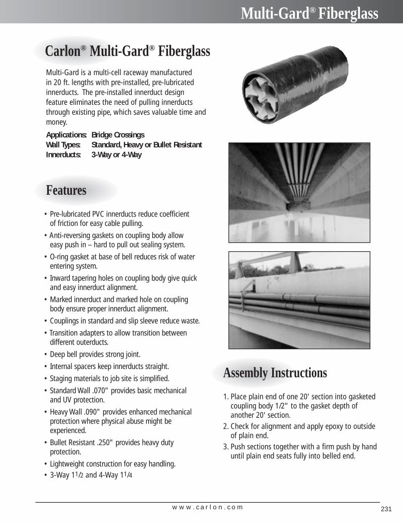
w w w . c a r l o n . c o m 231
Multi-Gard® Fiberglass
Multi-Gard is a multi-cell raceway manufactured in 20 ft. lengths with pre-installed, pre-lubricatedinnerducts. The pre-installed innerduct design feature eliminates the need of pulling innerductsthrough existing pipe, which saves valuable time andmoney.
Applications: Bridge CrossingsWall Types: Standard, Heavy or Bullet ResistantInnerducts: 3-Way or 4-Way
• Pre-lubricated PVC innerducts reduce coefficient of friction for easy cable pulling.
• Anti-reversing gaskets on coupling body allow easy push in – hard to pull out sealing system.
• O-ring gasket at base of bell reduces risk of waterentering system.
• Inward tapering holes on coupling body give quickand easy innerduct alignment.
• Marked innerduct and marked hole on couplingbody ensure proper innerduct alignment.
• Couplings in standard and slip sleeve reduce waste.
• Transition adapters to allow transition between different outerducts.
• Deep bell provides strong joint.
• Internal spacers keep innerducts straight.
• Staging materials to job site is simplified.
• Standard Wall .070" provides basic mechanical and UV protection.
• Heavy Wall .090" provides enhanced mechanicalprotection where physical abuse might be experienced.
• Bullet Resistant .250" provides heavy duty protection.
• Lightweight construction for easy handling.• 3-Way 11/2 and 4-Way 11/4
Carlon® Multi-Gard® Fiberglass
Features
1. Place plain end of one 20' section into gasketedcoupling body 1/2" to the gasket depth ofanother 20' section.
2. Check for alignment and apply epoxy to outsideof plain end.
3. Push sections together with a firm push by handuntil plain end seats fully into belled end.
Assembly Instructions
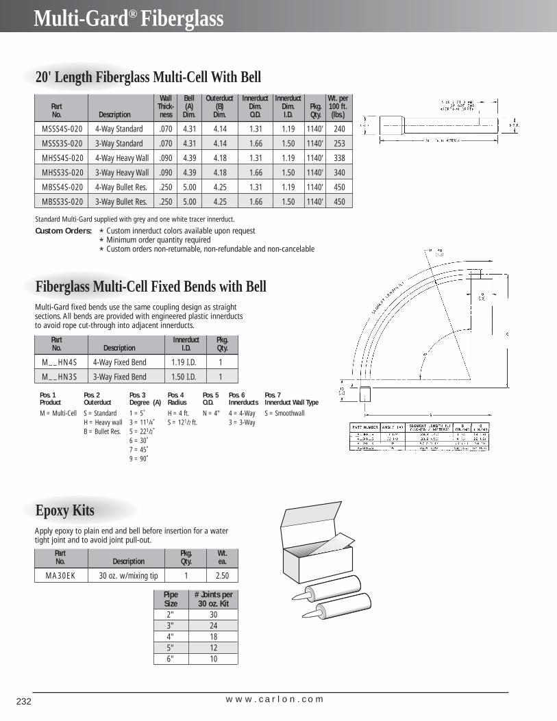
w w w . c a r l o n . c o m232
Multi-Gard® Fiberglass
20' Length Fiberglass Multi-Cell With BellWall Bell Outerduct Innerduct Innerduct Wt. per
Part Thick- (A) (B) Dim. Dim. Pkg. 100 ft.No. Description ness Dim. Dim. O.D. I.D. Qty. (lbs.)
MSSS4S-020 4-Way Standard .070 4.31 4.14 1.31 1.19 1140' 240
MSSS3S-020 3-Way Standard .070 4.31 4.14 1.66 1.50 1140' 253
MHSS4S-020 4-Way Heavy Wall .090 4.39 4.18 1.31 1.19 1140' 338
MHSS3S-020 3-Way Heavy Wall .090 4.39 4.18 1.66 1.50 1140' 340
MBSS4S-020 4-Way Bullet Res. .250 5.00 4.25 1.31 1.19 1140' 450
MBSS3S-020 3-Way Bullet Res. .250 5.00 4.25 1.66 1.50 1140' 450
Standard Multi-Gard supplied with grey and one white tracer innerduct.
Custom Orders: * Custom innerduct colors available upon request* Minimum order quantity required* Custom orders non-returnable, non-refundable and non-cancelable
Fiberglass Multi-Cell Fixed Bends with Bell
Part Innerduct Pkg.No. Description I.D. Qty.
M__HN4S 4-Way Fixed Bend 1.19 I.D. 1
M__HN3S 3-Way Fixed Bend 1.50 I.D. 1
Pos. 1 Pos. 2 Pos. 3 Pos. 4 Pos. 5 Pos. 6 Pos. 7Product Outerduct Degree (A) Radius O.D. Innerducts Innerduct Wall Type
M = Multi-Cell S = Standard 1 = 5˚ H = 4 ft. N = 4" 4 = 4-Way S = SmoothwallH = Heavy wall 3 = 111/4˚ S = 121/2 ft. 3 = 3-WayB = Bullet Res. 5 = 221/2˚
6 = 30˚7 = 45˚9 = 90˚
Multi-Gard fixed bends use the same coupling design as straightsections. All bends are provided with engineered plastic innerductsto avoid rope cut-through into adjacent innerducts.
Epoxy Kits
Part Pkg. Wt.No. Description Qty. ea.
MA30EK 30 oz. w/mixing tip 1 2.50
Apply epoxy to plain end and bell before insertion for a watertight joint and to avoid joint pull-out.
Pipe # Joints perSize 30 oz. Kit2" 303" 244" 185" 126" 10
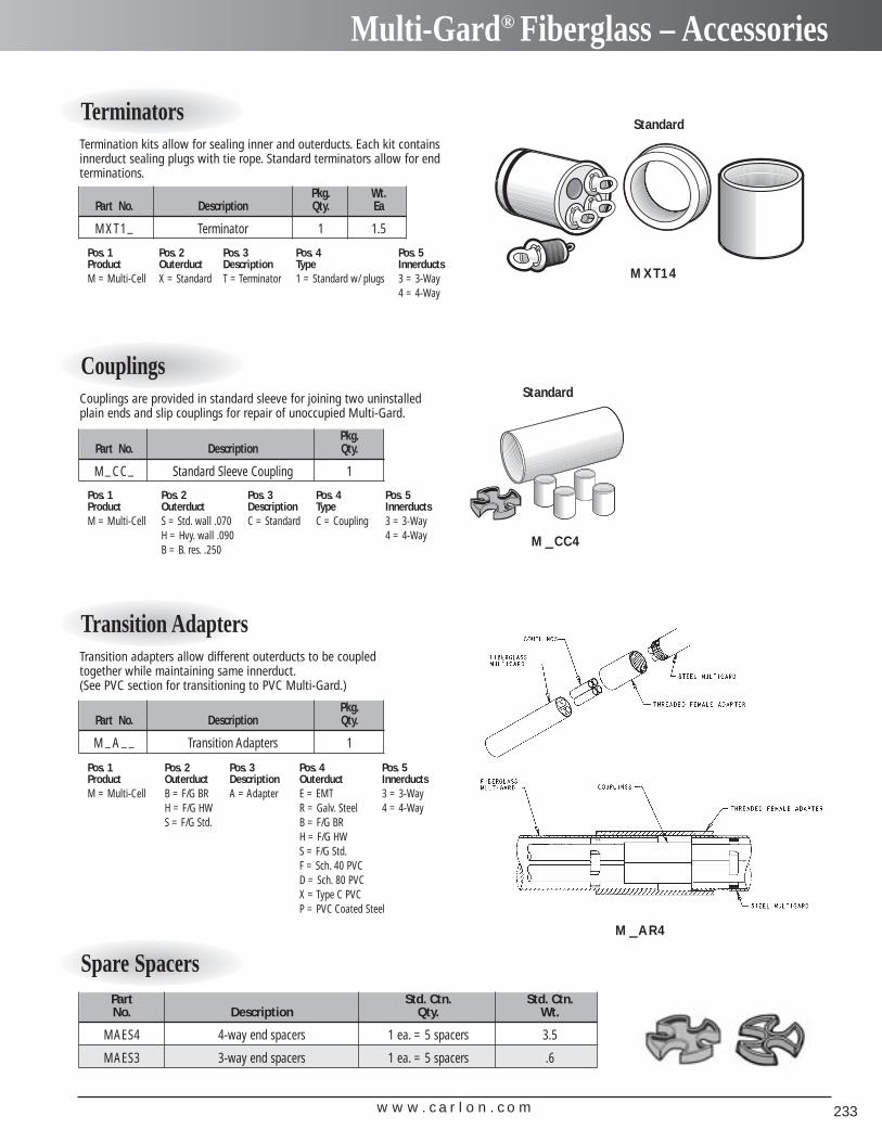
w w w . c a r l o n . c o m 233
Multi-Gard® Fiberglass – Accessories
Standard
Standard
MXT14
M CC4–
M AR4–
Terminators
Pkg. Wt.Part No. Description Qty. Ea
MXT1_ Terminator 1 1.5
Pos. 1 Pos. 2 Pos. 3 Pos. 4 Pos. 5Product Outerduct Description Type InnerductsM = Multi-Cell X = Standard T = Terminator 1 = Standard w/ plugs 3 = 3-Way
4 = 4-Way
Termination kits allow for sealing inner and outerducts. Each kit containsinnerduct sealing plugs with tie rope. Standard terminators allow for endterminations.
Couplings
Pkg.Part No. Description Qty.
M_CC_ Standard Sleeve Coupling 1
Pos. 1 Pos. 2 Pos. 3 Pos. 4 Pos. 5Product Outerduct Description Type InnerductsM = Multi-Cell S = Std. wall .070 C = Standard C = Coupling 3 = 3-Way
H = Hvy. wall .090 4 = 4-WayB = B. res. .250
Couplings are provided in standard sleeve for joining two uninstalledplain ends and slip couplings for repair of unoccupied Multi-Gard.
Transition Adapters
Pkg.Part No. Description Qty.
M _A __ Transition Adapters 1
Pos. 1 Pos. 2 Pos. 3 Pos. 4 Pos. 5Product Outerduct Description Outerduct InnerductsM = Multi-Cell B = F/G BR A = Adapter E = EMT 3 = 3-Way
H = F/G HW R = Galv. Steel 4 = 4-WayS = F/G Std. B = F/G BR
H = F/G HWS = F/G Std.F = Sch. 40 PVCD = Sch. 80 PVCX = Type C PVCP = PVC Coated Steel
Transition adapters allow different outerducts to be coupledtogether while maintaining same innerduct.(See PVC section for transitioning to PVC Multi-Gard.)
Spare SpacersPart Std. Ctn. Std. Ctn.No. Description Qty. Wt.
MAES4 4-way end spacers 1 ea. = 5 spacers 3.5
MAES3 3-way end spacers 1 ea. = 5 spacers .6
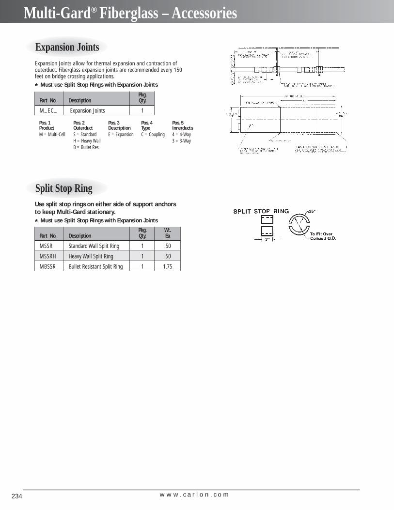
w w w . c a r l o n . c o m234
Multi-Gard® Fiberglass – Accessories
Split Stop Ring
Pkg. Wt.Part No. Description Qty. Ea
MSSR Standard Wall Split Ring 1 .50
MSSRH Heavy Wall Split Ring 1 .50
MBSSR Bullet Resistant Split Ring 1 1.75
Use split stop rings on either side of support anchors to keep Multi-Gard stationary.
* Must use Split Stop Rings with Expansion Joints
Expansion Joints
Pkg.Part No. Description Qty.
M_EC_ Expansion Joints 1
Expansion Joints allow for thermal expansion and contraction ofouterduct. Fiberglass expansion joints are recommended every 150feet on bridge crossing applications.
* Must use Split Stop Rings with Expansion Joints
Pos. 1 Pos. 2 Pos. 3 Pos. 4 Pos. 5Product Outerduct Description Type InnerductsM = Multi-Cell S = Standard E = Expansion C = Coupling 4 = 4-Way
H = Heavy Wall 3 = 3-WayB = Bullet Res.

w w w . c a r l o n . c o m 235
Multi-Gard® Galvanized Steel
Multi-Gard Galvanized Steel is a multiple celledraceway system designed for bridge applicationsand other areas requiring heavy duty protection.Multi-Gard is manufactured in 10 ft. lengths withpre-installed, pre-lubricated, smoothwallinnerducts.
Applications: Bridge applications and areasrequiring extra protection
Innerducts: 3-Way or 4-Way
• Pre-lubricated PVC innerducts for very low co-efficient of friction and lay straight for long pulls.
• Pre-installed reverse spin coupling allows couplingMulti-Gard together without turning pipe.
• 3 set screws keep coupling from backing off,before and after installation.
• Standard sweeps and terminators.
• Patented flexible bend.
• Conforms to NEC 96 Article 300-22 for installationof communication cables inside buildings.
• All bends have “cut-through” resistant innerducts inbends to avoid rope cutting into adjacent occupiedinnerduct.
• Accessories such as pull line and line blowing kitsavailable.
• Gasketed coupling body and PVC innerducts are designed to handle jetting equipment or lineblowing.
• 3-Way 11/2 and 4-Way 11/4
Carlon® Multi-Gard® Galvanized Steel
Features
1. Remove cap and loosen set screws on coupling.Spin back to allow for insertion.
2. Insert male into female end and spin coupling forward to bottom out.
3. Check for alignment of marked innerduct andmarked hole.
4. Tighten set screws.
Assembly Instructions
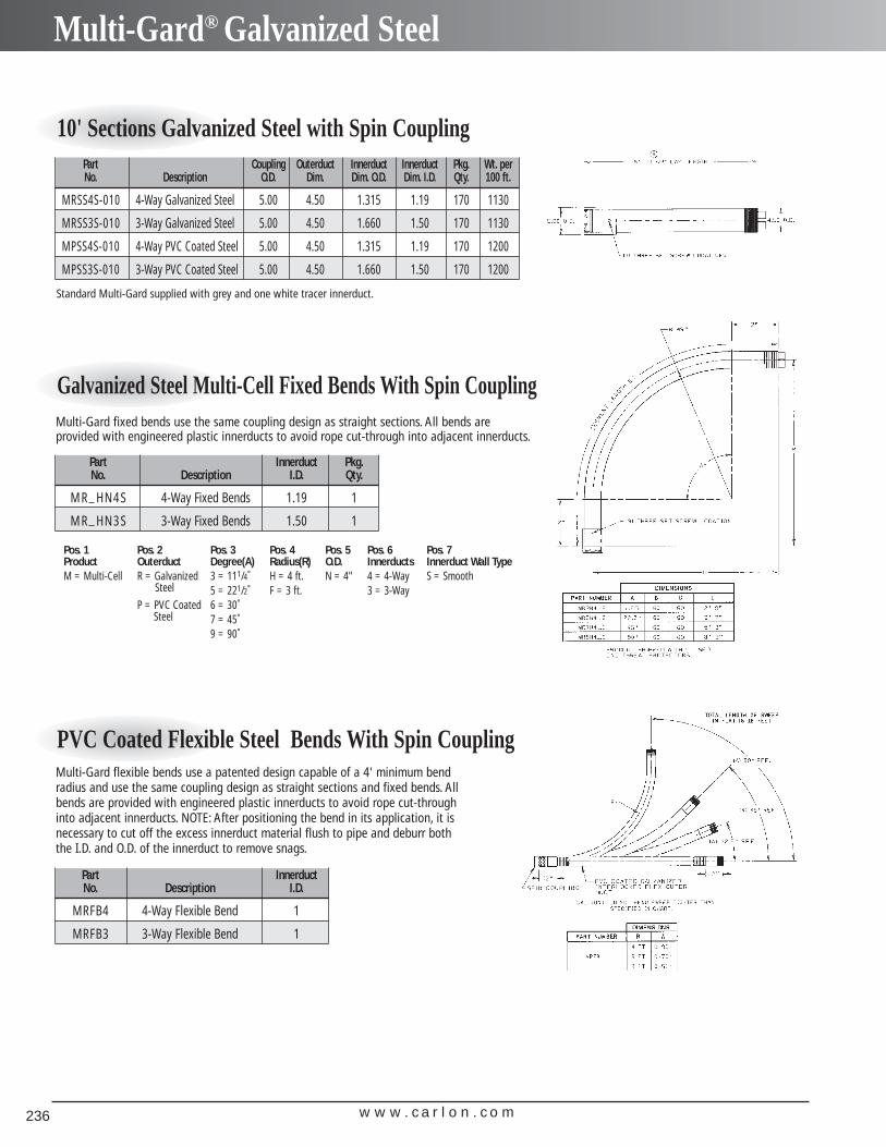
w w w . c a r l o n . c o m236
Multi-Gard® Galvanized Steel
10' Sections Galvanized Steel with Spin CouplingPart Coupling Outerduct Innerduct Innerduct Pkg. Wt. perNo. Description O.D. Dim. Dim. O.D. Dim. I.D. Qty. 100 ft.
MRSS4S-010 4-Way Galvanized Steel 5.00 4.50 1.315 1.19 170 1130
MRSS3S-010 3-Way Galvanized Steel 5.00 4.50 1.660 1.50 170 1130
MPSS4S-010 4-Way PVC Coated Steel 5.00 4.50 1.315 1.19 170 1200
MPSS3S-010 3-Way PVC Coated Steel 5.00 4.50 1.660 1.50 170 1200
Standard Multi-Gard supplied with grey and one white tracer innerduct.
Galvanized Steel Multi-Cell Fixed Bends With Spin Coupling
Part Innerduct Pkg.No. Description I.D. Qty.
MR_HN4S 4-Way Fixed Bends 1.19 1
MR_HN3S 3-Way Fixed Bends 1.50 1
Pos. 1 Pos. 2 Pos. 3 Pos. 4 Pos. 5 Pos. 6 Pos. 7Product Outerduct Degree(A) Radius(R) O.D. Innerducts Innerduct Wall TypeM = Multi-Cell R = Galvanized 3 = 111/4˚ H = 4 ft. N = 4" 4 = 4-Way S = Smooth
Steel 5 = 221/2˚ F = 3 ft. 3 = 3-WayP = PVC Coated 6 = 30˚
Steel 7 = 45˚9 = 90˚
Multi-Gard fixed bends use the same coupling design as straight sections. All bends are provided with engineered plastic innerducts to avoid rope cut-through into adjacent innerducts.
PVC Coated Flexible Steel Bends With Spin Coupling
Part InnerductNo. Description I.D.
MRFB4 4-Way Flexible Bend 1
MRFB3 3-Way Flexible Bend 1
Multi-Gard flexible bends use a patented design capable of a 4' minimum bendradius and use the same coupling design as straight sections and fixed bends. Allbends are provided with engineered plastic innerducts to avoid rope cut-throughinto adjacent innerducts. NOTE: After positioning the bend in its application, it isnecessary to cut off the excess innerduct material flush to pipe and deburr boththe I.D. and O.D. of the innerduct to remove snags.
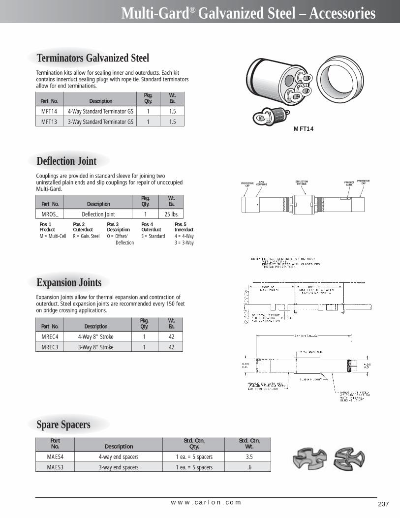
w w w . c a r l o n . c o m 237
Multi-Gard® Galvanized Steel – Accessories
MFT14
Terminators Galvanized Steel
Pkg. Wt.Part No. Description Qty. Ea.
MFT14 4-Way Standard Terminator GS 1 1.5
MFT13 3-Way Standard Terminator GS 1 1.5
Termination kits allow for sealing inner and outerducts. Each kit contains innerduct sealing plugs with rope tie. Standard terminatorsallow for end terminations.
Deflection Joint
Pkg. Wt.Part No. Description Qty. Ea.
MROS_ Deflection Joint 1 25 lbs.
Pos. 1 Pos. 2 Pos. 3 Pos. 4 Pos. 5Product Outerduct Description Outerduct InnerductM = Multi-Cell R = Galv. Steel O = Offset/ S = Standard 4 = 4-Way
Deflection 3 = 3-Way
Couplings are provided in standard sleeve for joining two uninstalled plain ends and slip couplings for repair of unoccupiedMulti-Gard.
Expansion Joints
Pkg. Wt.Part No. Description Qty. Ea.
MREC4 4-Way 8" Stroke 1 42
MREC3 3-Way 8" Stroke 1 42
Expansion Joints allow for thermal expansion and contraction ofouterduct. Steel expansion joints are recommended every 150 feeton bridge crossing applications.
Spare SpacersPart Std. Ctn. Std. Ctn.No. Description Qty. Wt.
MAES4 4-way end spacers 1 ea. = 5 spacers 3.5
MAES3 3-way end spacers 1 ea. = 5 spacers .6
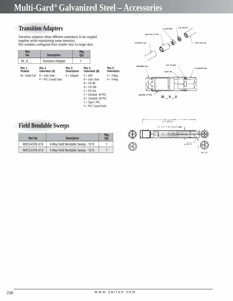
w w w . c a r l o n . c o m238
Multi-Gard® Galvanized Steel – Accessories
Transition Adapters
Part Pkg.No. Description Qty.
M_A__ Transition Adapter 1
Pos. 1 Pos. 2 Pos. 3 Pos. 4 Pos. 5Product Outerduct (A) Description Outerduct (B) Innerducts
M = Multi-Cell R = Galv. Steel A = Adapter E = EMT 3 = 3-WayP = PVC Coated Steel R = Galv. Steel 4 = 4-Way
B = F/G BRH = F/G HWS = F/G Std.F = Schedule 40 PVCD = Schedule 80 PVCC = Type C PVCP = PVC Coated Steel
Transition adaptors allow different outerducts to be coupledtogether while maintaining same innerduct.Part numbers configured from smaller duct to larger duct.
Field Bendable Sweeps
M A 4– –
Pkg.Part No. Description Qty.
MRSS4SFB-010 4-Way Field Bendable Sweep - 10 ft. 1
MRSS3SFB-010 3-Way Field Bendable Sweep - 10 ft. 1
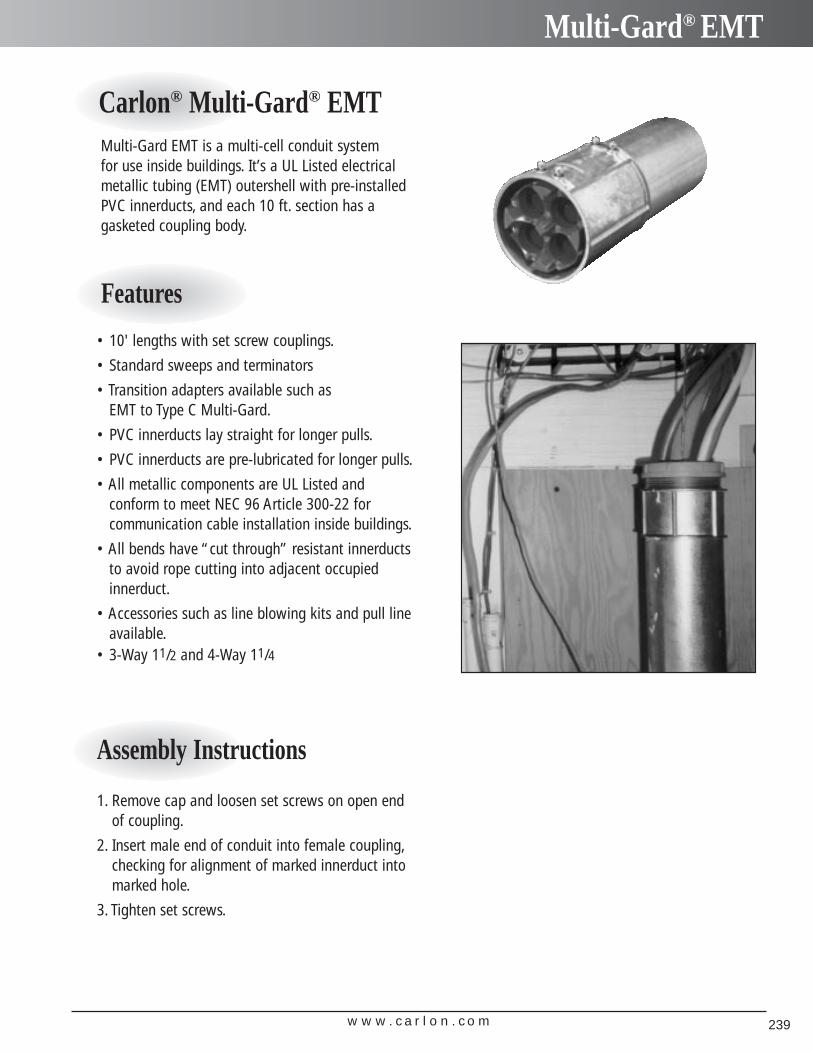
w w w . c a r l o n . c o m 239
Multi-Gard® EMT
Multi-Gard EMT is a multi-cell conduit system for use inside buildings. It’s a UL Listed electricalmetallic tubing (EMT) outershell with pre-installed PVC innerducts, and each 10 ft. section has a gasketed coupling body.
• 10' lengths with set screw couplings.
• Standard sweeps and terminators
• Transition adapters available such as EMT to Type C Multi-Gard.
• PVC innerducts lay straight for longer pulls.
• PVC innerducts are pre-lubricated for longer pulls.
• All metallic components are UL Listed and conform to meet NEC 96 Article 300-22 for communication cable installation inside buildings.
• All bends have “cut through” resistant innerductsto avoid rope cutting into adjacent occupiedinnerduct.
• Accessories such as line blowing kits and pull lineavailable.
• 3-Way 11/2 and 4-Way 11/4
Carlon® Multi-Gard® EMT
Features
1. Remove cap and loosen set screws on open endof coupling.
2. Insert male end of conduit into female coupling,checking for alignment of marked innerduct intomarked hole.
3. Tighten set screws.
Assembly Instructions
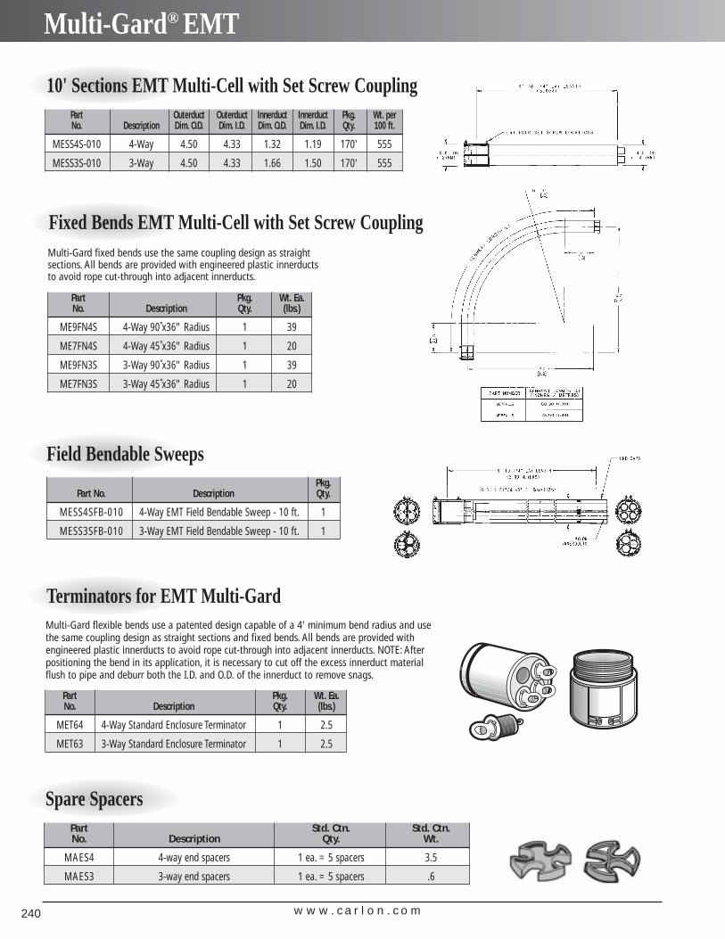
w w w . c a r l o n . c o m240
Multi-Gard® EMT
10' Sections EMT Multi-Cell with Set Screw CouplingPart Outerduct Outerduct Innerduct Innerduct Pkg. Wt. perNo. Description Dim. O.D. Dim. I.D. Dim. O.D. Dim. I.D. Qty. 100 ft.
MESS4S-010 4-Way 4.50 4.33 1.32 1.19 170' 555
MESS3S-010 3-Way 4.50 4.33 1.66 1.50 170' 555
Fixed Bends EMT Multi-Cell with Set Screw Coupling
Part Pkg. Wt. Ea.No. Description Qty. (lbs.)
ME9FN4S 4-Way 90˚x36" Radius 1 39
ME7FN4S 4-Way 45˚x36" Radius 1 20
ME9FN3S 3-Way 90˚x36" Radius 1 39
ME7FN3S 3-Way 45˚x36" Radius 1 20
Multi-Gard fixed bends use the same coupling design as straightsections. All bends are provided with engineered plastic innerductsto avoid rope cut-through into adjacent innerducts.
Terminators for EMT Multi-Gard
Part Pkg. Wt. Ea.No. Description Qty. (lbs.)
MET64 4-Way Standard Enclosure Terminator 1 2.5
MET63 3-Way Standard Enclosure Terminator 1 2.5
Multi-Gard flexible bends use a patented design capable of a 4' minimum bend radius and usethe same coupling design as straight sections and fixed bends. All bends are provided withengineered plastic innerducts to avoid rope cut-through into adjacent innerducts. NOTE: Afterpositioning the bend in its application, it is necessary to cut off the excess innerduct materialflush to pipe and deburr both the I.D. and O.D. of the innerduct to remove snags.
Field Bendable SweepsPkg.
Part No. Description Qty.
MESS4SFB-010 4-Way EMT Field Bendable Sweep - 10 ft. 1
MESS3SFB-010 3-Way EMT Field Bendable Sweep - 10 ft. 1
Spare SpacersPart Std. Ctn. Std. Ctn.No. Description Qty. Wt.
MAES4 4-way end spacers 1 ea. = 5 spacers 3.5
MAES3 3-way end spacers 1 ea. = 5 spacers .6
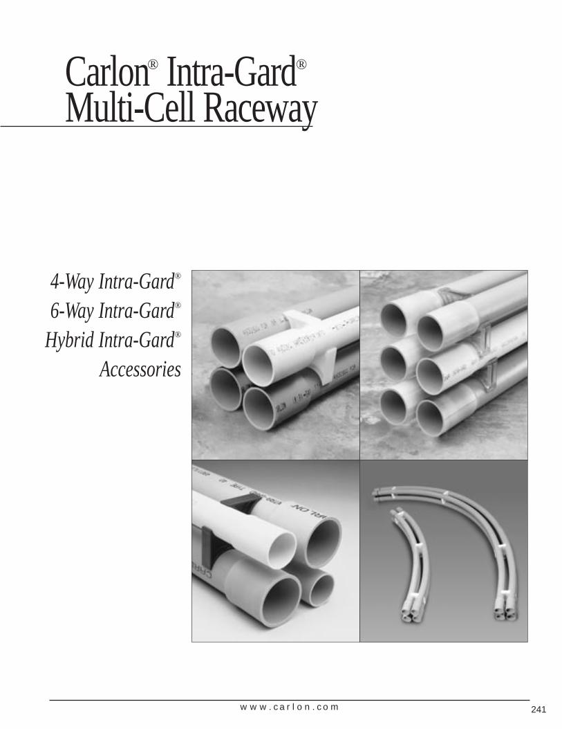
w w w . c a r l o n . c o m 241
Carlon® Intra-Gard®
Multi-Cell Raceway
4-Way Intra-Gard®
6-Way Intra-Gard®
Hybrid Intra-Gard®
Accessories
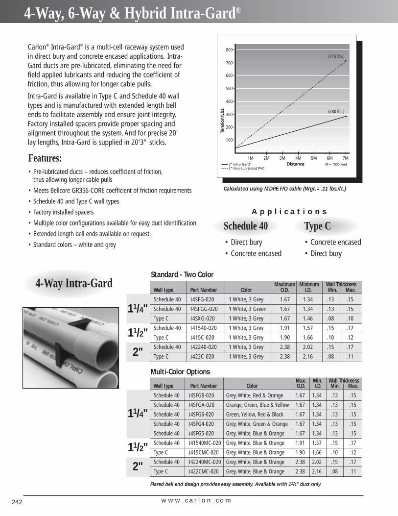
w w w . c a r l o n . c o m242
4-Way, 6-Way & Hybrid Intra-Gard®
Carlon® Intra-Gard® is a multi-cell raceway system usedin direct bury and concrete encased applications. Intra-Gard ducts are pre-lubricated, eliminating the need forfield applied lubricants and reducing the coefficient offriction, thus allowing for longer cable pulls.
Intra-Gard is available in Type C and Schedule 40 walltypes and is manufactured with extended length bellends to facilitate assembly and ensure joint integrity.Factory installed spacers provide proper spacing andalignment throughout the system. And for precise 20'lay lengths, Intra-Gard is supplied in 20'3" sticks.
Schedule 40• Direct bury• Concrete encased
Type C• Concrete encased• Direct bury
A p p l i c a t i o n s
Features:• Pre-lubricated ducts – reduces coefficient of friction,
thus allowing longer cable pulls
• Meets Bellcore GR356-CORE coefficient of friction requirements
• Schedule 40 and Type C wall types
• Factory installed spacers
• Multiple color configurations available for easy duct identification
• Extended length bell ends available on request
• Standard colors – white and grey
4-Way Intra-Gard Maximum Minimum Wall ThicknessWall type Part Number Color O.D. I.D. Min. Max.
Schedule 40 I4SFG-020 1 White, 3 Grey 1.67 1.34 .13 .15
Schedule 40 I4SFGG-020 1 White, 3 Green 1.67 1.34 .13 .15
Type C I4SXG-020 1 White, 3 Grey 1.67 1.46 .08 .10
Schedule 40 I41540-020 1 White, 3 Grey 1.91 1.57 .15 .17
Type C I415C-020 1 White, 3 Grey 1.90 1.66 .10 .12
Schedule 40 I42240-020 1 White, 3 Grey 2.38 2.02 .15 .17
Type C I422C-020 1 White, 3 Grey 2.38 2.16 .08 .11
11/4"
11/2"
2"
Standard - Two Color
Max. Min. Wall ThicknessWall type Part Number Color O.D. I.D. Min. Max.
Schedule 40 I4SFGB-020 Grey, White, Red & Orange 1.67 1.34 .13 .15
Schedule 40 I4SFGA-020 Orange, Green, Blue & Yellow 1.67 1.34 .13 .15
Schedule 40 I4SFG6-020 Green, Yellow, Red & Black 1.67 1.34 .13 .15
Schedule 40 I4SFG4-020 Grey, White, Green & Orange 1.67 1.34 .13 .15
Schedule 40 I4SFG5-020 Grey, White, Blue & Orange 1.67 1.34 .13 .15
Schedule 40 I41540MC-020 Grey, White, Blue & Orange 1.91 1.57 .15 .17
Type C I415CMC-020 Grey, White, Blue & Orange 1.90 1.66 .10 .12
Schedule 40 I42240MC-020 Grey, White, Blue & Orange 2.38 2.02 .15 .17
Type C I422CMC-020 Grey, White, Blue & Orange 2.38 2.16 .08 .11
11/4"
11/2"
2"
Multi-Color Options
Calculated using MDPE F/O cable (Wgt.= .11 lbs./ft.)
Flared bell end design provides easy assembly. Available with 11/4" duct only.
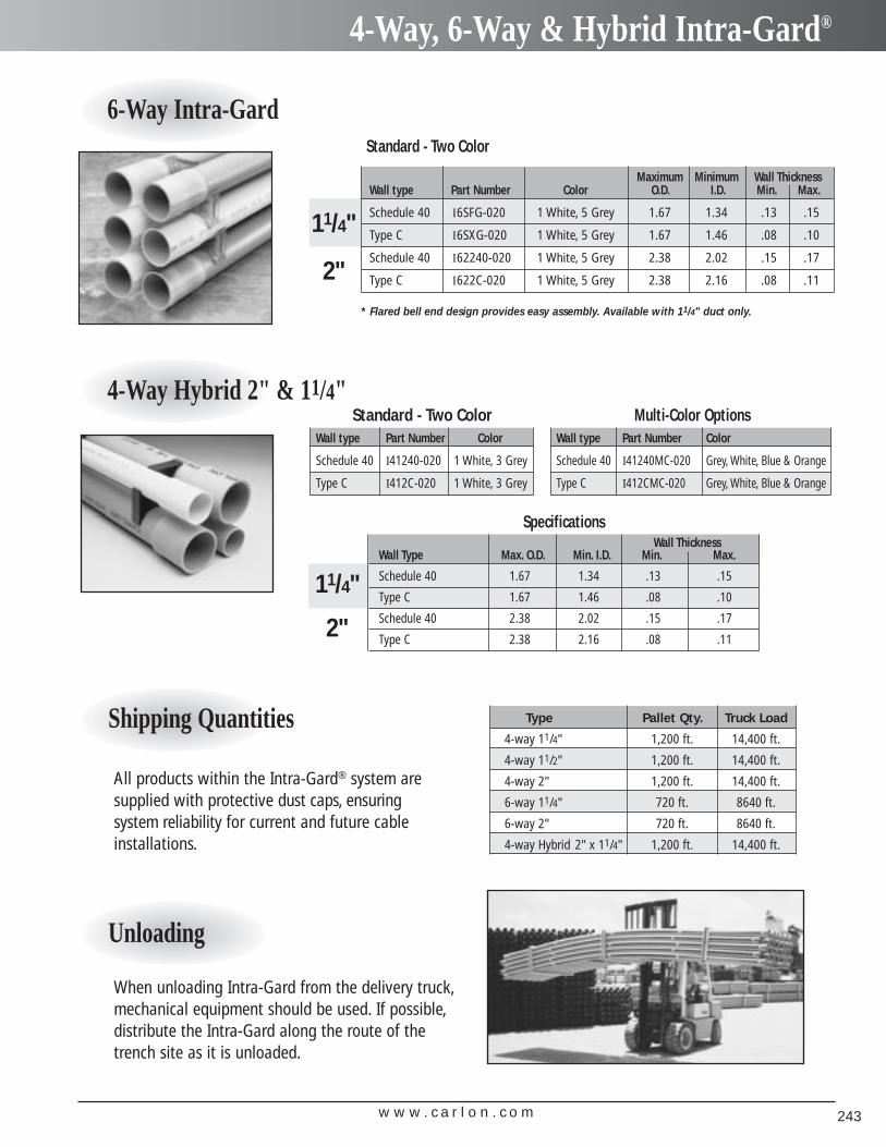
w w w . c a r l o n . c o m 243
4-Way, 6-Way & Hybrid Intra-Gard®
6-Way Intra-Gard
Maximum Minimum Wall ThicknessWall type Part Number Color O.D. I.D. Min. Max.
Schedule 40 I6SFG-020 1 White, 5 Grey 1.67 1.34 .13 .15
Type C I6SXG-020 1 White, 5 Grey 1.67 1.46 .08 .10
Schedule 40 I62240-020 1 White, 5 Grey 2.38 2.02 .15 .17
Type C I622C-020 1 White, 5 Grey 2.38 2.16 .08 .11
11/4"
2"
4-Way Hybrid 2" & 11/4"
Wall type Part Number Color
Schedule 40 I41240-020 1 White, 3 Grey
Type C I412C-020 1 White, 3 Grey
Standard - Two ColorWall type Part Number Color
Schedule 40 I41240MC-020 Grey, White, Blue & Orange
Type C I412CMC-020 Grey, White, Blue & Orange
Multi-Color Options
Wall ThicknessWall Type Max. O.D. Min. I.D. Min. Max.
Schedule 40 1.67 1.34 .13 .15
Type C 1.67 1.46 .08 .10
Schedule 40 2.38 2.02 .15 .17
Type C 2.38 2.16 .08 .11
11/4"
2"
Specifications
* Flared bell end design provides easy assembly. Available with 11/4" duct only.
Standard - Two Color
Unloading
When unloading Intra-Gard from the delivery truck,mechanical equipment should be used. If possible,distribute the Intra-Gard along the route of thetrench site as it is unloaded.
Shipping Quantities
All products within the Intra-Gard® system aresupplied with protective dust caps, ensuringsystem reliability for current and future cableinstallations.
Type Pallet Qty. Truck Load
4-way 11/4" 1,200 ft. 14,400 ft.
4-way 11/2" 1,200 ft. 14,400 ft.
4-way 2" 1,200 ft. 14,400 ft.
6-way 11/4" 720 ft. 8640 ft.
6-way 2" 720 ft. 8640 ft.
4-way Hybrid 2" x 11/4" 1,200 ft. 14,400 ft.
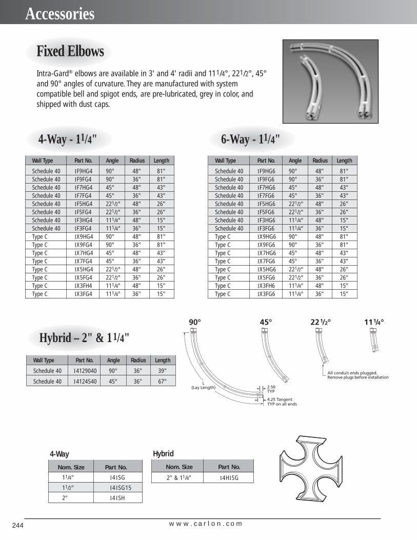
w w w . c a r l o n . c o m244
Accessories
Fixed Elbows Intra-Gard® elbows are available in 3' and 4' radii and 111/4°, 221/2°, 45°and 90° angles of curvature. They are manufactured with system compatible bell and spigot ends, are pre-lubricated, grey in color, andshipped with dust caps.
4-Way - 11/4"
Hybrid – 2" & 11/4"
6-Way - 11/4"
4-Way
Nom. Size Part No.
11/4" I4 ISG
11/2" I4 ISG15
2" I4 ISH
Hybrid
Nom. Size Part No.
2" & 11/4" I4HISG
Wall Type Part No. Angle Radius Length
Schedule 40 IF9HG4 90° 48" 81"Schedule 40 IF9FG4 90° 36" 81"Schedule 40 IF7HG4 45° 48" 43"Schedule 40 IF7FG4 45° 36" 43"Schedule 40 IF5HG4 221/2° 48" 26"Schedule 40 IF5FG4 221/2° 36" 26"Schedule 40 IF3HG4 111/4° 48" 15"Schedule 40 IF3FG4 111/4° 36" 15"Type C IX9HG4 90° 48" 81"Type C IX9FG4 90° 36" 81"Type C IX7HG4 45° 48" 43"Type C IX7FG4 45° 36" 43"Type C IX5HG4 221/2° 48" 26"Type C IX5FG4 221/2° 36" 26"Type C IX3FH4 111/4° 48" 15"Type C IX3FG4 111/4° 36" 15"
Wall Type Part No. Angle Radius Length
Schedule 40 IF9HG6 90° 48" 81"Schedule 40 IF9FG6 90° 36" 81"Schedule 40 IF7HG6 45° 48" 43"Schedule 40 IF7FG6 45° 36" 43"Schedule 40 IF5HG6 221/2° 48" 26"Schedule 40 IF5FG6 221/2° 36" 26"Schedule 40 IF3HG6 111/4° 48" 15"Schedule 40 IF3FG6 111/4° 36" 15"Type C IX9HG6 90° 48" 81"Type C IX9FG6 90° 36" 81"Type C IX7HG6 45° 48" 43"Type C IX7FG6 45° 36" 43"Type C IX5HG6 221/2° 48" 26"Type C IX5FG6 221/2° 36" 26"Type C IX3FH6 111/4° 48" 15"Type C IX3FG6 111/4° 36" 15"
Wall Type Part No. Angle Radius Length
Schedule 40 I4129040 90° 36" 39"
Schedule 40 I4124540 45° 36" 67"
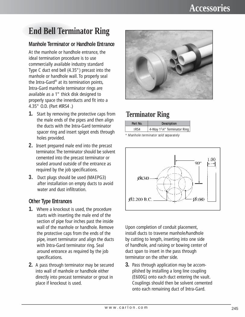
w w w . c a r l o n . c o m 245
Accessories
End Bell Terminator RingManhole Terminator or Handhole EntranceAt the manhole or handhole entrance, theideal termination procedure is to use commercially available industry standard Type C duct end bell (4.35") precast into themanhole or handhole wall. To properly seal the Intra-Gard® at its termination points,Intra-Gard manhole terminator rings are available as a 1" thick disk designed to properly space the innerducts and fit into a4.35" O.D. (Part #IRS4 .)
1. Start by removing the protective caps fromthe male ends of the pipes and then alignthe ducts with the Intra-Gard terminatorspacer ring and insert spigot ends throughholes provided.
2. Insert prepared male end into the precastterminator. The terminator should be solventcemented into the precast terminator orsealed around outside of the entrance asrequired by the job specifications.
3. Duct plugs should be used (MAEPG3)after installation on empty ducts to avoidwater and dust infiltration.
Other Type Entrances1. Where a knockout is used, the procedure
starts with inserting the male end of thesection of pipe four inches past the insidewall of the manhole or handhole. Removethe protective caps from the ends of thepipe, insert terminator and align the ductswith Intra-Gard terminator ring. Seal around entrance as required by the job specifications.
2. A pass through terminator may be securedinto wall of manhole or handhole eitherdirectly into precast terminator or grout inplace if knockout is used.
Upon completion of conduit placement,install ducts to traverse manhole/handhole by cutting to length, inserting into one side of handhole, and raising or bowing center of duct span to insert in the pass through terminator on the other side.
3. Pass through application may be accom-plished by installing a long line coupling(E600G) onto each duct entering the vault.Couplings should then be solvent cementedonto each remaining duct of Intra-Gard.
Part No. Description
IRS4 4-Way 11/4" Terminator Ring
* Manhole terminator sold separately
Terminator Ring
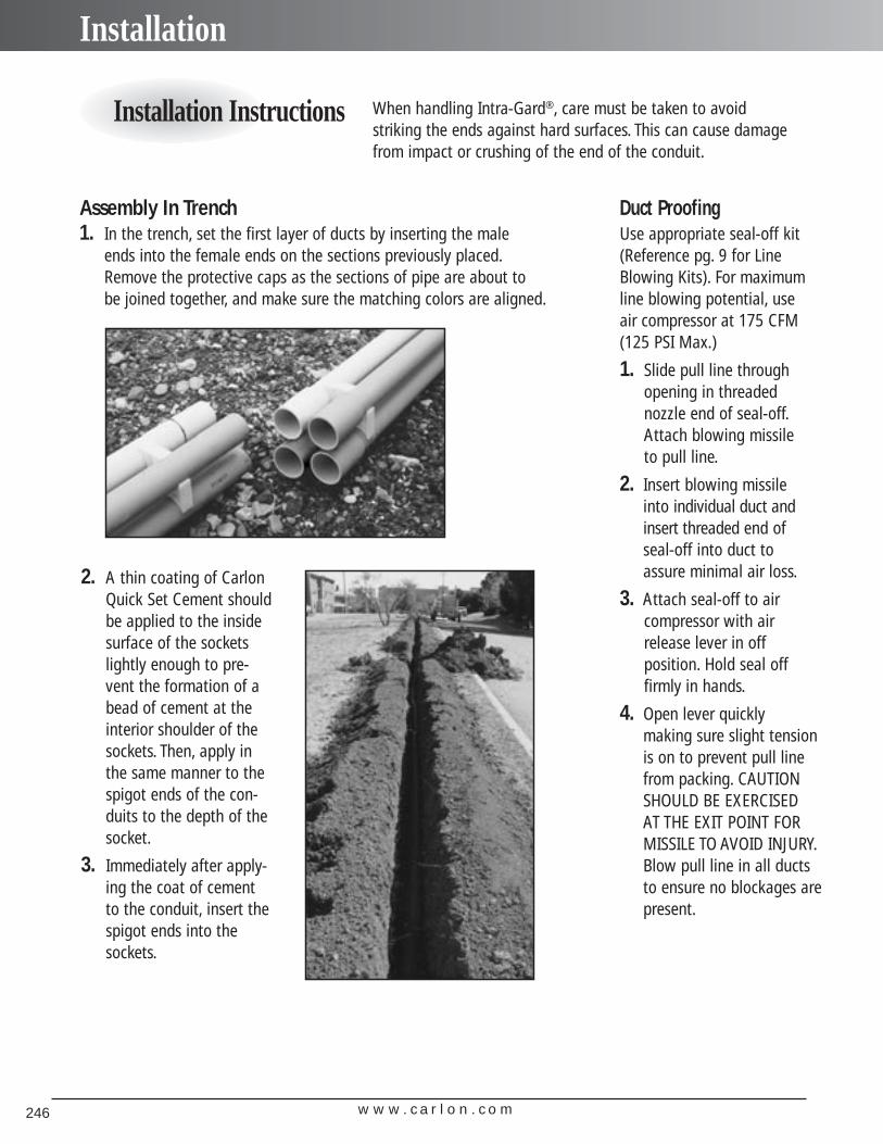
w w w . c a r l o n . c o m246
Installation
Duct ProofingUse appropriate seal-off kit(Reference pg. 9 for LineBlowing Kits). For maximumline blowing potential, use air compressor at 175 CFM(125 PSI Max.)
1. Slide pull line throughopening in threaded nozzle end of seal-off.Attach blowing missile to pull line.
2. Insert blowing missile into individual duct andinsert threaded end of seal-off into duct to assure minimal air loss.
3. Attach seal-off to air compressor with airrelease lever in off position. Hold seal off firmly in hands.
4. Open lever quickly making sure slight tensionis on to prevent pull linefrom packing. CAUTIONSHOULD BE EXERCISED AT THE EXIT POINT FORMISSILE TO AVOID INJURY.Blow pull line in all ductsto ensure no blockages arepresent.
Installation Instructions When handling Intra-Gard®, care must be taken to avoid striking the ends against hard surfaces. This can cause damagefrom impact or crushing of the end of the conduit.
Assembly In Trench1. In the trench, set the first layer of ducts by inserting the male
ends into the female ends on the sections previously placed.Remove the protective caps as the sections of pipe are about to be joined together, and make sure the matching colors are aligned.
2. A thin coating of CarlonQuick Set Cement shouldbe applied to the insidesurface of the socketslightly enough to pre-vent the formation of abead of cement at theinterior shoulder of thesockets. Then, apply inthe same manner to thespigot ends of the con-duits to the depth of thesocket.
3. Immediately after apply-ing the coat of cementto the conduit, insert thespigot ends into thesockets.
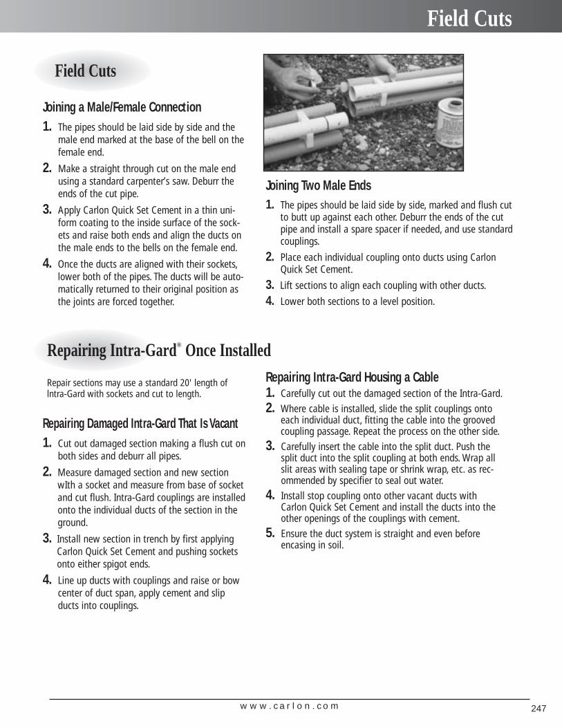
w w w . c a r l o n . c o m 247
Field Cuts
Joining a Male/Female Connection1. The pipes should be laid side by side and the
male end marked at the base of the bell on thefemale end.
2. Make a straight through cut on the male endusing a standard carpenter’s saw. Deburr theends of the cut pipe.
3. Apply Carlon Quick Set Cement in a thin uni-form coating to the inside surface of the sock-ets and raise both ends and align the ducts onthe male ends to the bells on the female end.
4. Once the ducts are aligned with their sockets,lower both of the pipes. The ducts will be auto-matically returned to their original position asthe joints are forced together.
Field Cuts
Repairing Damaged Intra-Gard That Is Vacant1. Cut out damaged section making a flush cut on
both sides and deburr all pipes.
2. Measure damaged section and new sectionwIth a socket and measure from base of socketand cut flush. Intra-Gard couplings are installedonto the individual ducts of the section in theground.
3. Install new section in trench by first applyingCarlon Quick Set Cement and pushing socketsonto either spigot ends.
4. Line up ducts with couplings and raise or bowcenter of duct span, apply cement and slipducts into couplings.
Repairing Intra-Gard® Once Installed
Joining Two Male Ends1. The pipes should be laid side by side, marked and flush cut
to butt up against each other. Deburr the ends of the cutpipe and install a spare spacer if needed, and use standardcouplings.
2. Place each individual coupling onto ducts using CarlonQuick Set Cement.
3. Lift sections to align each coupling with other ducts.
4. Lower both sections to a level position.
Repair sections may use a standard 20' length oflntra-Gard with sockets and cut to length.
Repairing Intra-Gard Housing a Cable1. Carefully cut out the damaged section of the Intra-Gard.
2. Where cable is installed, slide the split couplings ontoeach individual duct, fitting the cable into the groovedcoupling passage. Repeat the process on the other side.
3. Carefully insert the cable into the split duct. Push thesplit duct into the split coupling at both ends. Wrap allslit areas with sealing tape or shrink wrap, etc. as rec-ommended by specifier to seal out water.
4. Install stop coupling onto other vacant ducts withCarlon Quick Set Cement and install the ducts into theother openings of the couplings with cement.
5. Ensure the duct system is straight and even beforeencasing in soil.
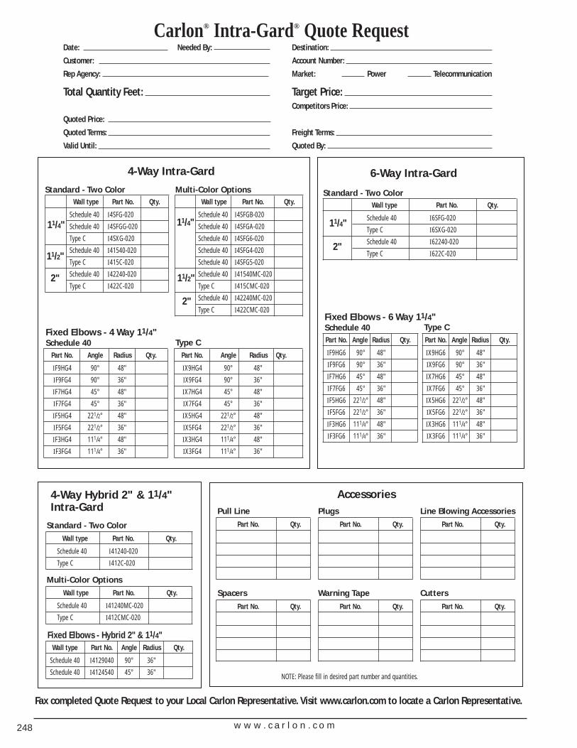
Carlon® Intra-Gard® Quote RequestDate: Needed By: Destination:
Customer: Account Number:
Rep Agency: Market: Power Telecommunication
Total Quantity Feet: Target Price:Competitors Price:
Quoted Price:
Quoted Terms: Freight Terms:
Valid Until: Quoted By:
4-Way Intra-Gard
Wall type Part No. Qty.
Schedule 40 I4SFG-020
Schedule 40 I4SFGG-020
Type C I4SXG-020
Schedule 40 I41540-020
Type C I415C-020
Schedule 40 I42240-020
Type C I422C-020
11/4"
11/2"
2"
Standard - Two Color
6-Way Intra-Gard
Wall type Part No. Qty.
Schedule 40 I6SFG-020
Type C I6SXG-020
Schedule 40 I62240-020
Type C I622C-020
11/4"
2"
Standard - Two ColorWall type Part No. Qty.
Schedule 40 I4SFGB-020
Schedule 40 I4SFGA-020
Schedule 40 I4SFG6-020
Schedule 40 I4SFG4-020
Schedule 40 I4SFG5-020
Schedule 40 I41540MC-020
Type C I415CMC-020
Schedule 40 I42240MC-020
Type C I422CMC-020
11/4"
11/2"
2"
Multi-Color Options
Accessories
Part No. Angle Radius Qty.
IF9HG4 90° 48"
IF9FG4 90° 36"
IF7HG4 45° 48"
IF7FG4 45° 36"
IF5HG4 221/2° 48"
IF5FG4 221/2° 36"
IF3HG4 111/4° 48"
IF3FG4 111/4° 36"
Part No. Angle Radius Qty.
IX9HG4 90° 48"
IX9FG4 90° 36"
IX7HG4 45° 48"
IX7FG4 45° 36"
IX5HG4 221/2° 48"
IX5FG4 221/2° 36"
IX3HG4 111/4° 48"
IX3FG4 111/4° 36"
Fixed Elbows - 4 Way 11/4"Schedule 40
Wall type Part No. Angle Radius Qty.
Schedule 40 I4129040 90° 36"
Schedule 40 I4124540 45° 36"
Fixed Elbows - Hybrid 2" & 11/4"
4-Way Hybrid 2" & 11/4"Intra-Gard
Wall type Part No. Qty.
Schedule 40 I41240-020
Type C I412C-020
Standard - Two Color
Pull Line
Spacers
Part No. Qty. Part No. Qty. Part No. Qty.
Part No. Qty. Part No. Qty. Part No. Qty.
Plugs
Warning Tape
Line Blowing Accessories
CuttersWall type Part No. Qty.
Schedule 40 I41240MC-020
Type C I412CMC-020
Multi-Color Options
NOTE: Please fill in desired part number and quantities.
Type C Part No. Angle Radius Qty.
IF9HG6 90° 48"
IF9FG6 90° 36"
IF7HG6 45° 48"
IF7FG6 45° 36"
IF5HG6 221/2° 48"
IF5FG6 221/2° 36"
IF3HG6 111/4° 48"
IF3FG6 111/4° 36"
Fixed Elbows - 6 Way 11/4"Schedule 40
Part No. Angle Radius Qty.
IX9HG6 90° 48"
IX9FG6 90° 36"
IX7HG6 45° 48"
IX7FG6 45° 36"
IX5HG6 221/2° 48"
IX5FG6 221/2° 36"
IX3HG6 111/4° 48"
IX3FG6 111/4° 36"
Type C
Fax completed Quote Request to your Local Carlon Representative. Visit www.carlon.com to locate a Carlon Representative.
w w w . c a r l o n . c o m248
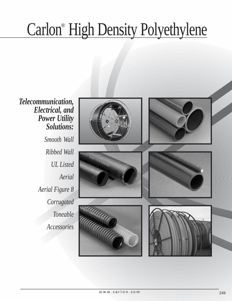
Telecommunication, Electrical, and
Power UtilitySolutions:
Smooth Wall
Ribbed Wall
UL Listed
Aerial
Aerial Figure 8
Corrugated
Toneable
Accessories
Carlon® High Density Polyethylene
w w w . c a r l o n . c o m 249
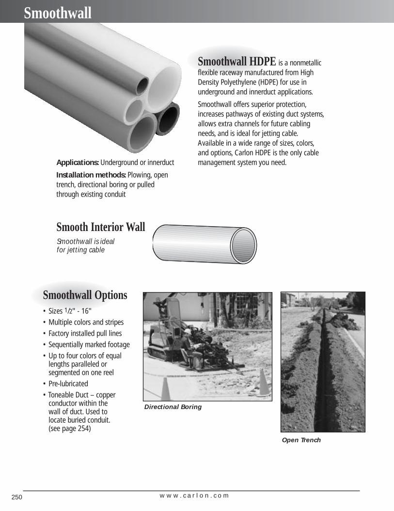
w w w . c a r l o n . c o m250
Smoothwall
Smooth Interior Wall
Applications: Underground or innerduct
Installation methods: Plowing, opentrench, directional boring or pulledthrough existing conduit
Smoothwall HDPE is a nonmetallicflexible raceway manufactured from HighDensity Polyethylene (HDPE) for use inunderground and innerduct applications.
Smoothwall offers superior protection,increases pathways of existing duct systems,allows extra channels for future cablingneeds, and is ideal for jetting cable.Available in a wide range of sizes, colors,and options, Carlon HDPE is the only cablemanagement system you need.
Smoothwall Options• Sizes 1/2" - 16"• Multiple colors and stripes• Factory installed pull lines• Sequentially marked footage• Up to four colors of equal
lengths paralleled or segmented on one reel
• Pre-lubricated• Toneable Duct – copper
conductor within the wall of duct. Used to locate buried conduit.(see page 254)
Smoothwall is ideal for jetting cable
Open Trench
Directional Boring
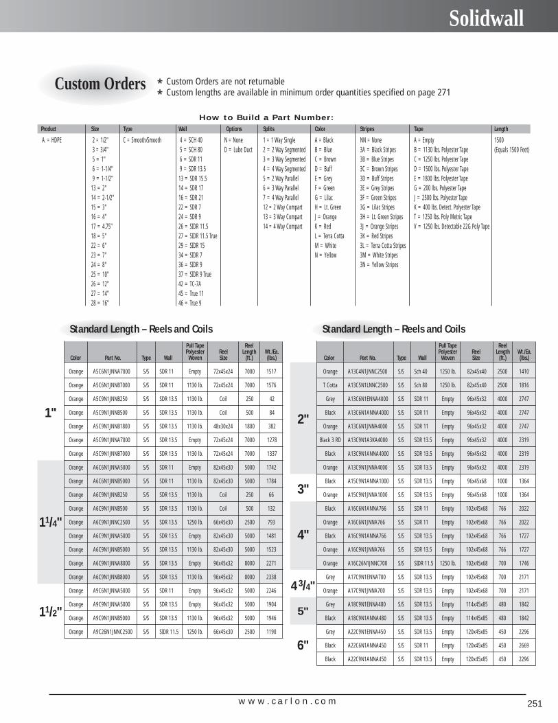
w w w . c a r l o n . c o m 251
Solidwall
How to Build a Part Number:Product Size Type Wall Options Splits Color Stripes Tape Length
A = HDPE 2 = 1/2" C = Smooth/Smooth 4 = SCH 40 N = None 1 = 1 Way Single A = Black NN = None A = Empty 15003 = 3/4" 5 = SCH 80 D = Lube Duct 2 = 2 Way Segmented B = Blue 3A = Black Stripes B = 1130 lbs. Polyester Tape (Equals 1500 Feet)5 = 1" 6 = SDR 11 3 = 3 Way Segmented C = Brown 3B = Blue Stripes C = 1250 lbs. Polyester Tape6 = 1-1/4" 9 = SDR 13.5 4 = 4 Way Segmented D = Buff 3C = Brown Stripes D = 1500 lbs. Polyester Tape9 = 1-1/2" 13 = SDR 15.5 5 = 2 Way Parallel E = Grey 3D = Buff Stripes E = 1800 lbs. Polyester Tape
13 = 2" 14 = SDR 17 6 = 3 Way Parallel F = Green 3E = Grey Stripes G = 200 lbs. Polyester Tape14 = 2-1/2" 16 = SDR 21 7 = 4 Way Parallel G = Lilac 3F = Green Stripes J = 2500 lbs. Polyester Tape15 = 3" 22 = SDR 7 12 = 2 Way Compart H = Lt. Green 3G = Lilac Stripes K = 400 lbs. Detect. Polyester Tape16 = 4" 24 = SDR 9 13 = 3 Way Compart J = Orange 3H = Lt. Green Stripes T = 1250 lbs. Poly Metric Tape17 = 4.75" 26 = SIDR 11.5 14 = 4 Way Compart K = Red 3J = Orange Stripes V = 1250 lbs. Detectable 22G Poly Tape18 = 5" 27 = SIDR 11.5 True L = Terra Cotta 3K = Red Stripes22 = 6" 29 = SIDR 15 M = White 3L = Terra Cotta Stripes23 = 7" 34 = SIDR 7 N = Yellow 3M = White Stripes24 = 8" 36 = SIDR 9 3N = Yellow Stripes25 = 10" 37 = SIDR 9 True26 = 12" 42 = TC-7A27 = 14" 45 = True 1128 = 16" 46 = True 9
Standard Length – Reels and CoilsPull Tape ReelPolyester Reel Length Wt./Ea.
Color Part No. Type Wall Woven Size (ft.) (lbs.)
Orange A5C6N1JNNA7000 S/S SDR 11 Empty 72x45x24 7000 1517
Orange A5C6N1JNNB7000 S/S SDR 11 1130 lb. 72x45x24 7000 1576
Orange A5C9N1JNNB250 S/S SDR 13.5 1130 lb. Coil 250 42
Orange A5C9N1JNNB500 S/S SDR 13.5 1130 lb. Coil 500 84
Orange A5C9N1JNNB1800 S/S SDR 13.5 1130 lb. 48x30x24 1800 382
Orange A5C9N1JNNA7000 S/S SDR 13.5 Empty 72x45x24 7000 1278
Orange A5C9N1JNNB7000 S/S SDR 13.5 1130 lb. 72x45x24 7000 1337
Orange A6C6N1JNNA5000 S/S SDR 11 Empty 82x45x30 5000 1742
Orange A6C6N1JNNB5000 S/S SDR 11 1130 lb. 82x45x30 5000 1784
Orange A6C9N1JNNB250 S/S SDR 13.5 1130 lb. Coil 250 66
Orange A6C9N1JNNB500 S/S SDR 13.5 1130 lb. Coil 500 132
Orange A6C9N1JNNC2500 S/S SDR 13.5 1250 lb. 66x45x30 2500 793
Orange A6C9N1JNNA5000 S/S SDR 13.5 Empty 82x45x30 5000 1481
Orange A6C9N1JNNB5000 S/S SDR 13.5 1130 lb. 82x45x30 5000 1523
Orange A6C9N1JNNA8000 S/S SDR 13.5 Empty 96x45x32 8000 2271
Orange A6C9N1JNNB8000 S/S SDR 13.5 1130 lb. 96x45x32 8000 2338
Orange A9C6N1JNNA5000 S/S SDR 11 Empty 96x45x32 5000 2246
Orange A9C9N1JNNA5000 S/S SDR 13.5 Empty 96x45x32 5000 1904
Orange A9C9N1JNNB5000 S/S SDR 13.5 1130 lb. 96x45x32 5000 1946
Orange A9C26N1JNNC2500 S/S SIDR 11.5 1250 lb. 66x45x30 2500 1190
1"
11/4"
11/2"
Standard Length – Reels and CoilsPull Tape ReelPolyester Reel Length Wt./Ea.
Color Part No. Type Wall Woven Size (ft.) (lbs.)
Orange A13C4N1JNNC2500 S/S Sch 40 1250 lb. 82x45x40 2500 1410
T Cotta A13C5N1LNNC2500 S/S Sch 80 1250 lb. 82x45x40 2500 1816
Grey A13C6N1ENNA4000 S/S SDR 11 Empty 96x45x32 4000 2747
Black A13C6N1ANNA4000 S/S SDR 11 Empty 96x45x32 4000 2747
Orange A13C6N1JNNA4000 S/S SDR 11 Empty 96x45x32 4000 2747
Black 3 RD A13C9N1A3KA4000 S/S SDR 13.5 Empty 96x45x32 4000 2319
Black A13C9N1ANNA4000 S/S SDR 13.5 Empty 96x45x32 4000 2319
Orange A13C9N1JNNA4000 S/S SDR 13.5 Empty 96x45x32 4000 2319
Black A15C9N1ANNA1000 S/S SDR 13.5 Empty 96x45x68 1000 1364
Orange A15C9N1JNNA1000 S/S SDR 13.5 Empty 96x45x68 1000 1364
Black A16C6N1ANNA766 S/S SDR 11 Empty 102x45x68 766 2022
Orange A16C6N1JNNA766 S/S SDR 11 Empty 102x45x68 766 2022
Black A16C9N1ANNA766 S/S SDR 13.5 Empty 102x45x68 766 1727
Orange A16C9N1JNNA766 S/S SDR 13.5 Empty 102x45x68 766 1727
Orange A16C26N1JNNC700 S/S SIDR 11.5 1250 lb. 102x45x68 700 1746
Grey A17C9N1ENNA700 S/S SDR 13.5 Empty 102x45x68 700 2171
Orange A17C9N1JNNA700 S/S SDR 13.5 Empty 102x45x68 700 2171
Grey A18C9N1ENNA480 S/S SDR 13.5 Empty 114x45x85 480 1842
Black A18C9N1ANNA480 S/S SDR 13.5 Empty 114x45x85 480 1842
Grey A22C9N1ENNA450 S/S SDR 13.5 Empty 120x45x85 450 2296
Black A22C6N1ANNA450 S/S SDR 11 Empty 120x45x85 450 2669
Black A22C9N1ANNA450 S/S SDR 13.5 Empty 120x45x85 450 2296
2"
3"
4"
4 3/4"
5"
6"
* Custom Orders are not returnable
* Custom lengths are available in minimum order quantities specified on page 271Custom Orders
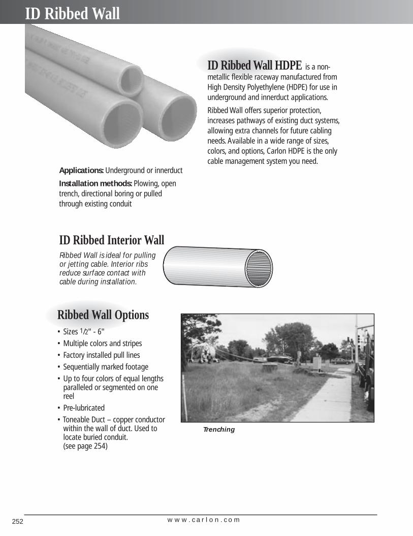
ID Ribbed Interior Wall
Applications: Underground or innerduct
Installation methods: Plowing, opentrench, directional boring or pulledthrough existing conduit
ID Ribbed Wall HDPE is a non-metallic flexible raceway manufactured fromHigh Density Polyethylene (HDPE) for use inunderground and innerduct applications.
Ribbed Wall offers superior protection,increases pathways of existing duct systems,allowing extra channels for future cablingneeds. Available in a wide range of sizes,colors, and options, Carlon HDPE is the onlycable management system you need.
Ribbed Wall Options• Sizes 1/2" - 6"• Multiple colors and stripes• Factory installed pull lines• Sequentially marked footage• Up to four colors of equal lengths
paralleled or segmented on onereel
• Pre-lubricated• Toneable Duct – copper conductor
within the wall of duct. Used tolocate buried conduit.(see page 254)
Ribbed Wall is ideal for pullingor jetting cable. Interior ribsreduce surface contact withcable during installation.
Trenching
w w w . c a r l o n . c o m252
ID Ribbed Wall
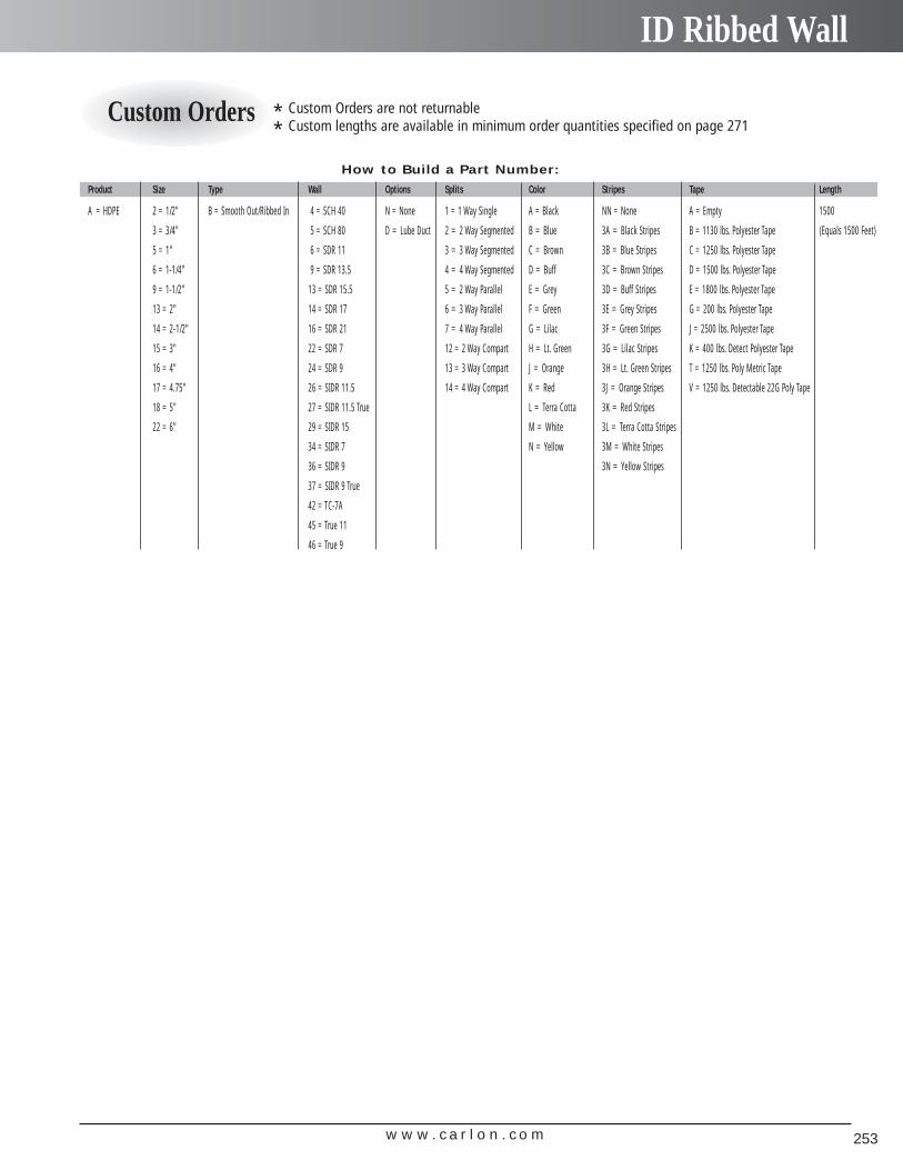
w w w . c a r l o n . c o m 253
ID Ribbed Wall
How to Build a Part Number:
Product Size Type Wall Options Splits Color Stripes Tape Length
A = HDPE 2 = 1/2" B = Smooth Out/Ribbed In 4 = SCH 40 N = None 1 = 1 Way Single A = Black NN = None A = Empty 1500
3 = 3/4" 5 = SCH 80 D = Lube Duct 2 = 2 Way Segmented B = Blue 3A = Black Stripes B = 1130 lbs. Polyester Tape (Equals 1500 Feet)
5 = 1" 6 = SDR 11 3 = 3 Way Segmented C = Brown 3B = Blue Stripes C = 1250 lbs. Polyester Tape
6 = 1-1/4" 9 = SDR 13.5 4 = 4 Way Segmented D = Buff 3C = Brown Stripes D = 1500 lbs. Polyester Tape
9 = 1-1/2" 13 = SDR 15.5 5 = 2 Way Parallel E = Grey 3D = Buff Stripes E = 1800 lbs. Polyester Tape
13 = 2" 14 = SDR 17 6 = 3 Way Parallel F = Green 3E = Grey Stripes G = 200 lbs. Polyester Tape
14 = 2-1/2" 16 = SDR 21 7 = 4 Way Parallel G = Lilac 3F = Green Stripes J = 2500 lbs. Polyester Tape
15 = 3" 22 = SDR 7 12 = 2 Way Compart H = Lt. Green 3G = Lilac Stripes K = 400 lbs. Detect Polyester Tape
16 = 4" 24 = SDR 9 13 = 3 Way Compart J = Orange 3H = Lt. Green Stripes T = 1250 lbs. Poly Metric Tape
17 = 4.75" 26 = SIDR 11.5 14 = 4 Way Compart K = Red 3J = Orange Stripes V = 1250 lbs. Detectable 22G Poly Tape
18 = 5" 27 = SIDR 11.5 True L = Terra Cotta 3K = Red Stripes
22 = 6" 29 = SIDR 15 M = White 3L = Terra Cotta Stripes
34 = SIDR 7 N = Yellow 3M = White Stripes
36 = SIDR 9 3N = Yellow Stripes
37 = SIDR 9 True
42 = TC-7A
45 = True 11
46 = True 9
* Custom Orders are not returnable
* Custom lengths are available in minimum order quantities specified on page 271Custom Orders

w w w . c a r l o n . c o m254
Toneable
Toneable HDPE Duct incorporates apatented design using bare solid copper conductorwire within the duct wall underneath a LDPE orHDPE stripe providing easy access to the conductorwire for grounding and coupling applications.
Allows detectability and toning isolation of emptyduct structures as well as ducts with dielectric fiberinstallations using conventional transmission,receiving, and locating equipment.
Standard metal and nonmetallic coupling methods allow conduit detectability and non-metallic toneable pressure couplings allow detection/toning isolation of conduit.
Complete system of conduit and couplings provides the solution to finding buried occupied or non-occupied conduits.
Toneable Options• Industry standard conduit sizes 1"– 2"• Solid bare copper tone wire• Use Conventional locating devices • Tone wire easily accessible for coupling
and grounding• Standard/compression couplings available
(page 269)• Allows isolation tone and/or detection• Suitable for direct bury, bore, trench
applications• Single color stripe option
Open Trench
Application: Underground
Installation methods: Direct bury,directional boring, or trench
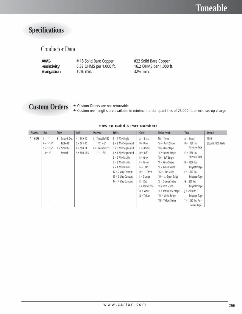
w w w . c a r l o n . c o m 255
Toneable
AWG # 18 Solid Bare Copper #22 Solid Bare CopperResistivity 6.39 OHMS per 1,000 ft. 16.2 OHMS per 1,000 ft.Elongation 10% min. 32% min.
How to Build a Part Number:
Product Size Type Wall Options Splits Color Stripe (one) Tape Length
A = HDPE 5 = 1" B = Smooth Out/ 4 = SCH 40 J = Toneable/18G 1 = 1 Way Single A = Black NN = None A = Empty 1500
6 = 1-1/4" Ribbed In 5 = SCH 80 1 1/2" – 2" 2 = 2 Way Segmented B = Blue 1A = Black Stripe B = 1130 lbs. (Equals 1500 Feet)
9 = 1-1/2" C = Smooth/ 6 = SDR 11 G = Toneable/22G 3 = 3 Way Segmented C = Brown 1B = Blue Stripe Polyester Tape
13 = 2" Smooth 9 = SDR 13.5 1" – 1 1/4" 4 = 4 Way Segmented D = Buff 1C = Brown Stripe C = 1250 lbs.
5 = 2 Way Parallel E = Grey 1D = Buff Stripe Polyester Tape
6 = 3 Way Parallel F = Green 1E = Grey Stripe D = 1500 lbs.
7 = 4 Way Parallel G = Lilac 1F = Green Stripe Polyester Tape
12 = 2 Way Compart H = Lt. Green 1G = Lilac Stripe E = 1800 lbs.
13 = 3 Way Compart J = Orange 1H = Lt. Green Stripe Polyester Tape
14 = 4 Way Compart K = Red 1J = Orange Stripe G = 200 lbs.
L = Terra Cotta 1K = Red Stripe Polyester Tape
M = White 1L = Terra Cotta Stripe J = 2500 lbs.
N = Yellow 1M = White Stripe Polyester Tape
1N = Yellow Stripe T = 1250 lbs. Poly
Metric Tape
Conductor Data
Specifications
* Custom Orders are not returnable
* Custom reel lengths are available in minimum order quantities of 25,000 ft. or min. set up chargeCustom Orders
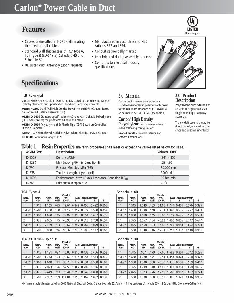
w w w . c a r l o n . c o m256
Carlon® Power Cable in Duct
• Cables preinstalled in HDPE - eliminatingthe need to pull cables.
• Standard wall thicknesses of TC7 Type A,TC7 Type B (SDR 13.5), Schedule 40 andSchedule 80
• UL Listed duct assembly (upon request)
ConduitNom. Nom. Nom. Min. Wt/ Max Cable Diameter*Size OD ID Wall 100 Ft. 1 2 3 4
1" 1.315 1.165 .075 12.64 0.842 0.456 0.422 0.366
1-1/4" 1.660 1.460 .100 21.19 1.057 0.572 0.530 0.459
1-1/2" 1.900 1.670 .115 27.89 1.210 0.654 0.607 0.526
2" 2.375 2.085 .145 43.93 1.512 0.818 0.758 0.657
2-1/2" 2.875 2.469 .203 73.69 1.792 0.969 0.899 0.778
3" 3.500 3.068 .216 96.37 2.228 1.205 1.117 0.968
TC7 Type AConduit
Nom. Nom. Nom. Min. Wt/ Max Cable Diameter*Size OD ID Wall 100 Ft. 1 2 3 4
1" 1.315 1.049 .133 21.68 0.749 0.405 0.376 0.325
1-1/4" 1.660 1.380 .140 29.31 0.990 0.535 0.497 0.430
1-1/2" 1.900 1.610 .145 35.00 1.158 0.626 0.581 0.503
2" 2.375 2.067 .154 46.92 1.490 0.806 0.747 0.647
2-1/2" 2.875 2.469 .203 74.00 1.783 0.964 0.894 0.774
3" 3.500 3.040 .216 97.31 2.213 1.197 1.110 0.961
ConduitNom. Nom. Nom. Min. Wt/ Max Cable Diameter*Size OD ID Wall 100 Ft. 1 2 3 4
1" 1.315 1.121 .097 16.05 0.810 0.438 0.406 0.352
1-1/4" 1.660 1.414 .123 25.68 1.024 0.554 0.513 0.445
1-1/2" 1.900 1.618 .141 33.70 1.172 0.634 0.588 0.509
2" 2.375 2.023 .176 52.58 1.467 0.793 0.736 0.637
2-1/2" 2.875 2.449 .213 76.41 1.755 0.949 0.880 0.762
3" 3.500 2.982 .259 114.04 2.158 1.167 1.082 0.937
ConduitNom. Nom. Nom. Min. Wt/ Max Cable Diameter*Size OD ID Wall 100 Ft. 1 2 3 4
1" 1.315 .957 .179 27.66 0.682 0.369 0.342 0.296
1-1/4" 1.660 1.278 .191 38.11 0.914 0.494 0.459 0.397
1-1/2" 1.900 1.500 .200 46.30 1.075 0.581 0.539 0.467
2" 2.375 1.939 .218 64.08 1.393 0.753 0.699 0.605
2-1/2" 2.875 2.323 .276 97.59 1.668 0.902 0.837 0.724
3" 3.500 2.900 .300 130.92 2.085 1.128 1.046 0.906
Schedule 40
TC7 SDR 13.5 Type B Schedule 80
3.0 ProductDescriptionPolyethylene duct extruded as coilable tubing for use as asingle or multiple racewayassembly.
The conduit assembly may bedirect buried, encased in con-crete and used as innerducts.
2.0 MaterialCarlon duct is manufactured from a suitable thermoplastic polymer conformingto the minimum standard of PE334470E/Cas defined in ASTM D3350. (see table 1)
Carlon® High DensityPolyethylene duct is manufacturedin the following configuration:
Smoothwall – Smooth Interior andSmooth Exterior wall.
1.0 GeneralCarlon HDPE Power Cable In Duct is manufactured to the following variousindustry standards and specifications for dimensional requirements.
ASTM F 2160 Solid Wall High Density Polyethylene (HDPE) Conduit Basedon Controlled Outside Diameter (OD).
ASTM D 3485 Standard specification for Smoothwall Coilable Polyethylene(PE) Conduit (duct) for preassembled wire and cable.
ASTM D 3035 Polyethylene (PE) Plastic Pipe (SDR) Based on ControlledOutside Diameter.
NEMA TC-7 Smooth Wall Coilable Polyethylene Electrical Plastic Conduit.
UL 651B Continuous length HDPE
Table 1 – Resin Properties The resin properties shall meet or exceed the values listed below for HDPE.ASTM Test Description Values HDPE
D-1505 Density g/CM3 .941 - .955
D-1238 Melt Index, g/10 min Condition E .05 - .50
D-790 Flexural Modulus, MPa (PSI) 80,000 min.
D-638 Tensile strength at yield (psi) 3000 min.
D-1693 Environmental Stress Crack Resistance Condition B,F10 96 hrs. min.
D-746 Brittleness Temperature -75˚C
*Maximum cable diameter based on 2002 National Electrical Code, Chapter 9 Article 352 Table 4 - fill percentages of: 1 Cable 53%; 2 Cables 31%; 3 or more Cables 40%.
• Manufactured in accordance to NECArticles 352 and 354.
• Conduit sequentially marked• Prelubricated during assembly process• Conforms to electrical industry
specifications
Upon RequestFeatures
Specifications
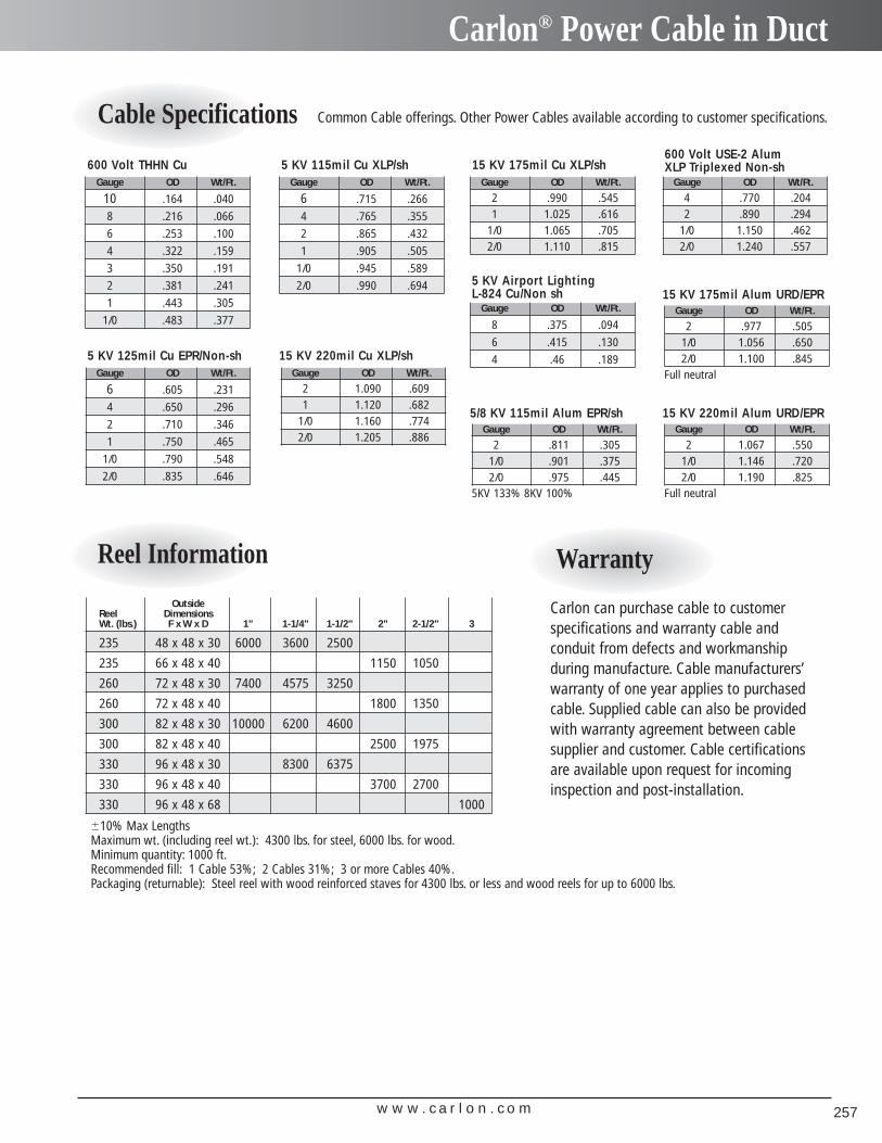
w w w . c a r l o n . c o m 257
Carlon® Power Cable in Duct
Cable Specifications
Reel Information Warranty
Gauge OD Wt/Ft.
10 .164 .040
8 .216 .066
6 .253 .100
4 .322 .159
3 .350 .191
2 .381 .241
1 .443 .305
1/0 .483 .377
600 Volt THHN CuGauge OD Wt/Ft.
6 .715 .266
4 .765 .355
2 .865 .432
1 .905 .505
1/0 .945 .589
2/0 .990 .694
5 KV 115mil Cu XLP/sh
Gauge OD Wt/Ft.
6 .605 .231
4 .650 .296
2 .710 .346
1 .750 .465
1/0 .790 .548
2/0 .835 .646
5 KV 125mil Cu EPR/Non-sh
Gauge OD Wt/Ft.
2 .990 .5451 1.025 .616
1/0 1.065 .7052/0 1.110 .815
15 KV 175mil Cu XLP/shGauge OD Wt/Ft.
4 .770 .2042 .890 .294
1/0 1.150 .4622/0 1.240 .557
Gauge OD Wt/Ft.
2 1.090 .6091 1.120 .682
1/0 1.160 .7742/0 1.205 .886
15 KV 220mil Cu XLP/sh
Gauge OD Wt/Ft.
2 1.067 .5501/0 1.146 .7202/0 1.190 .825
Full neutral
15 KV 220mil Alum URD/EPR
Gauge OD Wt/Ft.
2 .977 .5051/0 1.056 .6502/0 1.100 .845
Full neutral
15 KV 175mil Alum URD/EPR
Gauge OD Wt/Ft.
2 .811 .3051/0 .901 .3752/0 .975 .445
5KV 133% 8KV 100%
5/8 KV 115mil Alum EPR/sh
Gauge OD Wt/Ft.
8 .375 .094
6 .415 .130
4 .46 .189
OutsideReel DimensionsWt. (lbs.) F x W x D 1" 1-1/4" 1-1/2" 2" 2-1/2" 3
235 48 x 48 x 30 6000 3600 2500
235 66 x 48 x 40 1150 1050
260 72 x 48 x 30 7400 4575 3250
260 72 x 48 x 40 1800 1350
300 82 x 48 x 30 10000 6200 4600
300 82 x 48 x 40 2500 1975
330 96 x 48 x 30 8300 6375
330 96 x 48 x 40 3700 2700
330 96 x 48 x 68 1000
�10% Max LengthsMaximum wt. (including reel wt.): 4300 lbs. for steel, 6000 lbs. for wood.Minimum quantity: 1000 ft.Recommended fill: 1 Cable 53%; 2 Cables 31%; 3 or more Cables 40%.Packaging (returnable): Steel reel with wood reinforced staves for 4300 lbs. or less and wood reels for up to 6000 lbs.
Common Cable offerings. Other Power Cables available according to customer specifications.
Carlon can purchase cable to customer specifications and warranty cable and conduit from defects and workmanship during manufacture. Cable manufacturers’warranty of one year applies to purchasedcable. Supplied cable can also be providedwith warranty agreement between cablesupplier and customer. Cable certificationsare available upon request for incominginspection and post-installation.
5 KV Airport Lighting L-824 Cu/Non sh
600 Volt USE-2 AlumXLP Triplexed Non-sh
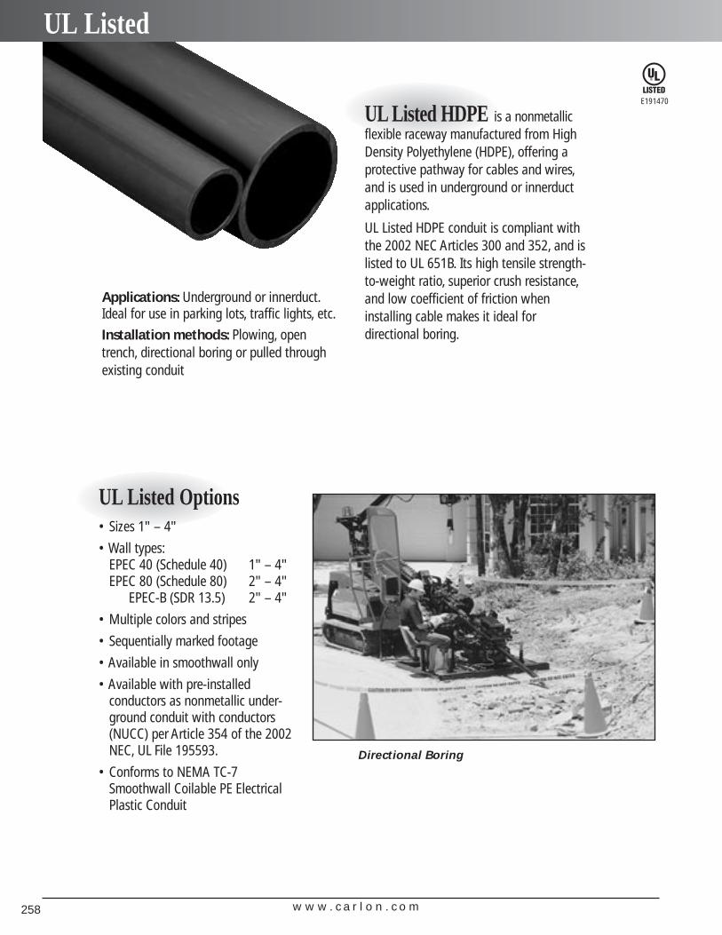
Applications: Underground or innerduct.Ideal for use in parking lots, traffic lights, etc.
Installation methods: Plowing, opentrench, directional boring or pulled throughexisting conduit
UL Listed HDPE is a nonmetallicflexible raceway manufactured from HighDensity Polyethylene (HDPE), offering a protective pathway for cables and wires,and is used in underground or innerductapplications.
UL Listed HDPE conduit is compliant withthe 2002 NEC Articles 300 and 352, and islisted to UL 651B. Its high tensile strength-to-weight ratio, superior crush resistance,and low coefficient of friction wheninstalling cable makes it ideal for directional boring.
UL Listed Options• Sizes 1" – 4"
• Wall types:EPEC 40 (Schedule 40) 1" – 4"EPEC 80 (Schedule 80) 2" – 4"
EPEC-B (SDR 13.5) 2" – 4"
• Multiple colors and stripes
• Sequentially marked footage
• Available in smoothwall only
• Available with pre-installed conductors as nonmetallic under-ground conduit with conductors(NUCC) per Article 354 of the 2002NEC, UL File 195593.
• Conforms to NEMA TC-7Smoothwall Coilable PE ElectricalPlastic Conduit
E191470
Directional Boring
w w w . c a r l o n . c o m258
UL Listed
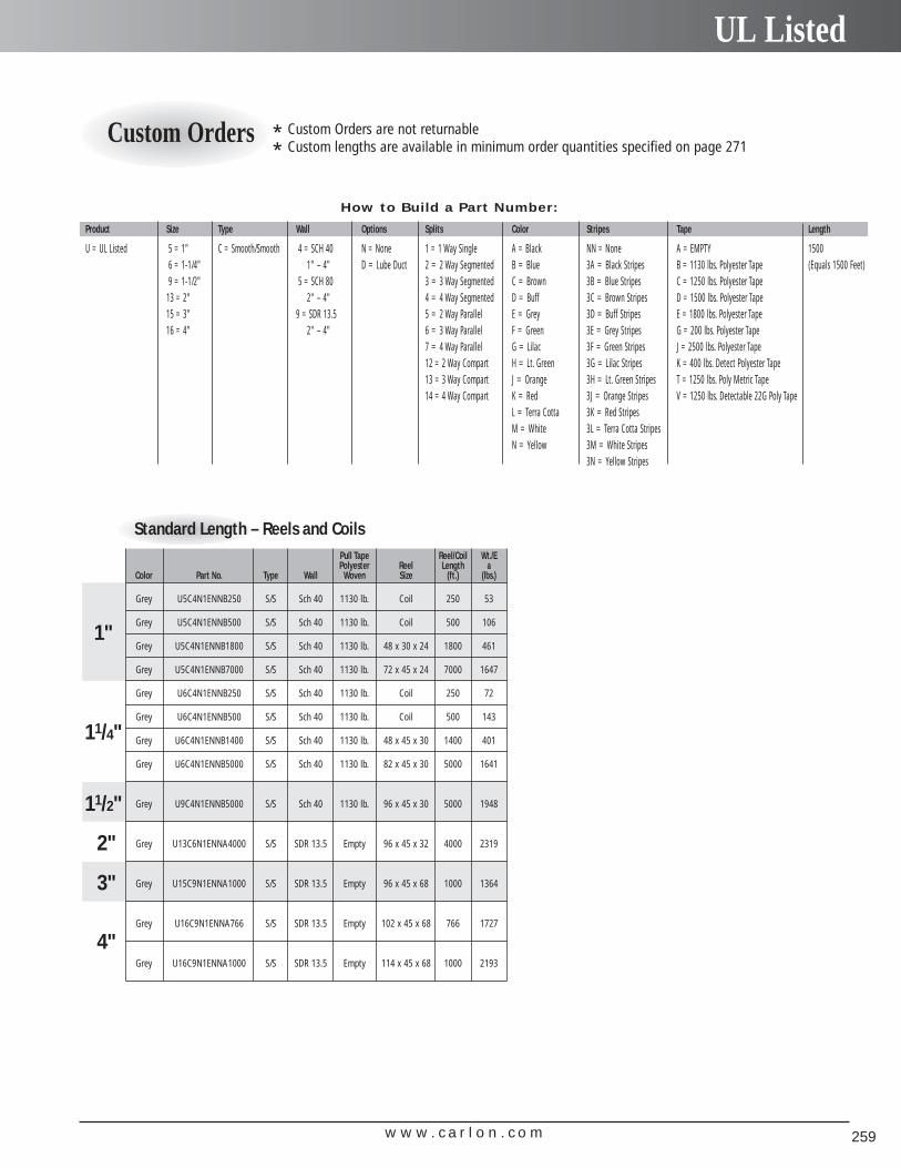
w w w . c a r l o n . c o m 259
UL Listed
How to Build a Part Number:
Product Size Type Wall Options Splits Color Stripes Tape Length
U = UL Listed 5 = 1" C = Smooth/Smooth 4 = SCH 40 N = None 1 = 1 Way Single A = Black NN = None A = EMPTY 15006 = 1-1/4" 1" – 4" D = Lube Duct 2 = 2 Way Segmented B = Blue 3A = Black Stripes B = 1130 lbs. Polyester Tape (Equals 1500 Feet)9 = 1-1/2" 5 = SCH 80 3 = 3 Way Segmented C = Brown 3B = Blue Stripes C = 1250 lbs. Polyester Tape
13 = 2" 2" – 4" 4 = 4 Way Segmented D = Buff 3C = Brown Stripes D = 1500 lbs. Polyester Tape15 = 3" 9 = SDR 13.5 5 = 2 Way Parallel E = Grey 3D = Buff Stripes E = 1800 lbs. Polyester Tape16 = 4" 2" – 4" 6 = 3 Way Parallel F = Green 3E = Grey Stripes G = 200 lbs. Polyester Tape
7 = 4 Way Parallel G = Lilac 3F = Green Stripes J = 2500 lbs. Polyester Tape12 = 2 Way Compart H = Lt. Green 3G = Lilac Stripes K = 400 lbs. Detect Polyester Tape13 = 3 Way Compart J = Orange 3H = Lt. Green Stripes T = 1250 lbs. Poly Metric Tape14 = 4 Way Compart K = Red 3J = Orange Stripes V = 1250 lbs. Detectable 22G Poly Tape
L = Terra Cotta 3K = Red StripesM = White 3L = Terra Cotta StripesN = Yellow 3M = White Stripes
3N = Yellow Stripes
* Custom Orders are not returnable
* Custom lengths are available in minimum order quantities specified on page 271Custom Orders
Standard Length – Reels and CoilsPull Tape Reel/Coil Wt./EPolyester Reel Length a
Color Part No. Type Wall Woven Size (ft.) (lbs.)
Grey U5C4N1ENNB250 S/S Sch 40 1130 lb. Coil 250 53
Grey U5C4N1ENNB500 S/S Sch 40 1130 lb. Coil 500 106
Grey U5C4N1ENNB1800 S/S Sch 40 1130 lb. 48 x 30 x 24 1800 461
Grey U5C4N1ENNB7000 S/S Sch 40 1130 lb. 72 x 45 x 24 7000 1647
Grey U6C4N1ENNB250 S/S Sch 40 1130 lb. Coil 250 72
Grey U6C4N1ENNB500 S/S Sch 40 1130 lb. Coil 500 143
Grey U6C4N1ENNB1400 S/S Sch 40 1130 lb. 48 x 45 x 30 1400 401
Grey U6C4N1ENNB5000 S/S Sch 40 1130 lb. 82 x 45 x 30 5000 1641
Grey U9C4N1ENNB5000 S/S Sch 40 1130 lb. 96 x 45 x 30 5000 1948
Grey U13C6N1ENNA4000 S/S SDR 13.5 Empty 96 x 45 x 32 4000 2319
Grey U15C9N1ENNA1000 S/S SDR 13.5 Empty 96 x 45 x 68 1000 1364
Grey U16C9N1ENNA766 S/S SDR 13.5 Empty 102 x 45 x 68 766 1727
Grey U16C9N1ENNA1000 S/S SDR 13.5 Empty 114 x 45 x 68 1000 2193
2"
3"
4"
1"
11/4"
11/2"
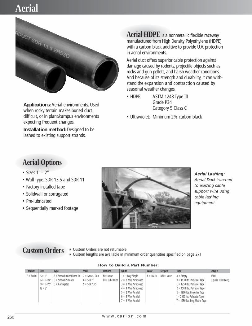
w w w . c a r l o n . c o m260
Aerial
Aerial HDPE is a nonmetallic flexible racewaymanufactured from High Density Polyethylene (HDPE)with a carbon black additive to provide U.V. protectionin aerial environments.
Aerial duct offers superior cable protection againstdamage caused by rodents, projectile objects such asrocks and gun pellets, and harsh weather conditions.And because of its strength and durability, it can with-stand the expansion and contraction caused by seasonal weather changes.
• HDPE: ASTM 1248 Type III Grade P34Category 5 Class C
• Ultraviolet: Minimum 2% carbon black
Applications: Aerial environments. Usedwhen rocky terrain makes buried duct difficult, or in plant/campus environmentsexpecting frequent changes.
Installation method: Designed to belashed to existing support strands.
Aerial Options• Sizes 1"– 2"• Wall Type: SDR 13.5 and SDR 11• Factory installed tape• Solidwall or corrugated• Pre-lubricated• Sequentially marked footage
Aerial Lashing:Aerial Duct is lashedto existing cable support wire usingcable lashing equipment.
How to Build a Part Number:
Product Size Type Wall Options Splits Color Stripes Tape Length
E = Aerial 5 = 1" B = Smooth Out/Ribbed In 2 = None - Corr N = None 1 = 1 Way Single A = Black NN = None A = Empty 15006 = 1-1/4" C = Smooth/Smooth 6 = SDR 11 D = Lube Duct 2 = 2 Way Partitioned B = 1130 lbs. Polyester Tape (Equals 1500 Feet)9 = 1-1/2" D = Corrugated 9 = SDR 13.5 3 = 3 Way Partitioned C = 1250 lbs. Polyester Tape
13 = 2" 4 = 4 Way Partitioned D = 1500 lbs. Polyester Tape5 = 2 Way Parallel E = 1800 lbs. Polyester Tape6 = 3 Way Parallel J = 2500 lbs. Polyester Tape7 = 4 Way Parallel T = 1250 lbs. Poly Metric Tape
* Custom Orders are not returnable
* Custom lengths are available in minimum order quantities specified on page 271Custom Orders
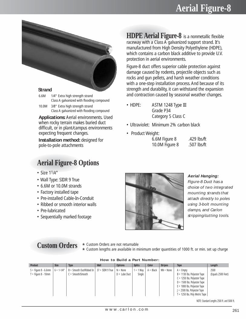
w w w . c a r l o n . c o m 261
Aerial Figure-8
6.6M 1/4" Extra high strength strandClass A galvanized with flooding compound
10.0M 3/8" Extra high strength strandClass A galvanized with flooding compound
Applications: Aerial environments. Usedwhen rocky terrain makes buried duct difficult, or in plant/campus environmentsexpecting frequent changes.Installation method: designed for pole-to-pole attachments
Strand
HDPE Aerial Figure-8 is a nonmetallic flexibleraceway with a Class A galvanized support strand. It’smanufactured from High Density Polyethylene (HDPE),which contains a carbon black additive to provide U.V.protection in aerial environments.
Figure-8 duct offers superior cable protection againstdamage caused by rodents, projectile objects such asrocks and gun pellets, and harsh weather conditionswith a one-step installation process. And because of itsstrength and durability, it can withstand the expansionand contraction caused by seasonal weather changes.
• HDPE: ASTM 1248 Type III Grade P34Category 5 Class C
• Ultraviolet: Minimum 2% carbon black
• Product Weight:6.6M Figure 8 .429 lbs/ft10.0M Figure 8 .507 lbs/ft
Aerial Figure-8 Options• Size 11/4"• Wall Type: SIDR 9 True• 6.6M or 10.0M strands• Factory installed tape• Pre-installed Cable-In-Conduit• Ribbed or smooth interior walls• Pre-lubricated• Sequentially marked footage
Aerial Hanging:Figure-8 Duct has achoice of two integratedmounting strands thatattach directly to polesusing 3-bolt mountingclamps, and Carlon stripping/cutting tools.
How to Build a Part Number:
Product Size Type Wall Options Splits Color Stripes Tape Length
S = Figure 8 - 6.6mm 6 = 1-1/4" B = Smooth Out/Ribbed In 37 = SIDR 9 True N = None 1 = 1 Way A = Black NN = None A = Empty 2500T = Figure 8 - 10mm C = Smooth/Smooth D = Lube Duct Single B = 1130 lbs. Polyester Tape (Equals 2500 Feet)
C = 1250 lbs. Polyester TapeD = 1500 lbs. Polyester TapeE = 1800 lbs. Polyester TapeJ = 2500 lbs. Polyester TapeT = 1250 lbs. Poly Metric Tape
* Custom Orders are not returnable
* Custom lengths are available in minimum order quantities of 1000 ft. or min. set up chargeCustom Orders
NOTE: Standard Lengths 2500 ft. and 5000 ft.
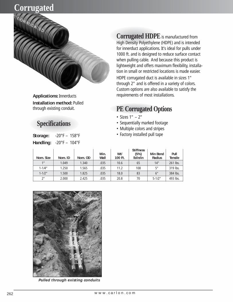
StiffnessMin. Wt/ (5%) Min Bend Pull
Nom. Size Nom. ID Nom. OD Wall 100 Ft. lb/in/in Radius Tensile
1" 1.049 1.340 .035 10.6 65 14" 261 lbs.
1-1/4" 1.250 1.565 .035 11.2 108 5" 319 lbs.
1-1/2" 1.500 1.825 .035 18.0 83 6" 384 lbs.
2" 2.000 2.425 .035 20.8 70 5-1/2" 493 lbs.
Specifications
Applications: Innerducts
Installation method: Pulled through existing conduit.
Storage: -20°F – 158°F
Handling: -20°F – 104°F
Corrugated HDPE is manufactured fromHigh Density Polyethylene (HDPE) and is intendedfor innerduct applications. It’s ideal for pulls under1000 ft. and is designed to reduce surface contactwhen pulling cable. And because this product islightweight and offers maximum flexibility, installa-tion in small or restricted locations is made easier.HDPE corrugated duct is available in sizes 1"through 2" and is offered in a variety of colors.Custom options are also available to satisfy therequirements of most installations.
PE Corrugated Options
Pulled through existing conduits
w w w . c a r l o n . c o m262
Corrugated
• Sizes 1" – 2"• Sequentially marked footage• Multiple colors and stripes• Factory installed pull tape
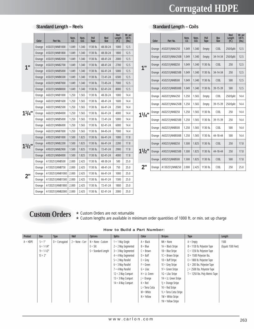
w w w . c a r l o n . c o m 263
Corrugated HDPE
Standard Length – Reels
Reel Wt. perNom. Nom. Pull Reel Length 100 ft.
Color Part No. I.D. O.D. Tape Size (ft.) (lbs.)
Orange A5D2S1JNNB1000 1.049 1.340 1130 lb. 48-30-24 1000 12.5
Orange A5D2S1JNNB1800 1.049 1.340 1130 lb. 48-30-24 1800 12.5
Orange A5D2S1JNNB2000 1.049 1.340 1130 lb. 48-41-24 2000 12.5
Orange A5D2S1JNNB2700 1.049 1.340 1130 lb. 48-41-24 2700 12.5
Orange A5D2S1JNNB5000 1.049 1.340 1130 lb. 66-41-24 5000 12.5
Orange A5D2S1JNNB6500 1.049 1.340 1130 lb. 72-41-24 6500 12.5
Orange A5D2S1JNNB7000 1.049 1.340 1130 lb. 72-45-24 7000 12.5
Orange A5D2S1JNNB8000 1.049 1.340 1130 lb. 82-41-24 8000 12.5
Orange A6D2S1JNNB1000 1.250 1.565 1130 lb. 48-30-24 1000 14.4
Orange A6D2S1JNNB1600 1.250 1.565 1130 lb. 48-41-24 1600 14.4
Orange A6D2S1JNNB2500 1.250 1.565 1130 lb. 66-41-24 2500 14.4
Orange A6D2S1JNNB4000 1.250 1.565 1130 lb. 66-41-24 4000 14.4
Orange A6D2S1JNNB5000 1.250 1.565 1130 lb. 72-41-24 5000 14.4
Orange A6D2S1JNNB6000 1.250 1.565 1130 lb. 82-41-24 6000 14.4
Orange A6D2S1JNNB7000 1.250 1.565 1130 lb. 84-45-24 7000 14.4
Orange A9D2S1JNNB1000 1.500 1.825 1130 lb. 66-41-24 1000 17.8
Orange A9D2S1JNNB2200 1.500 1.825 1130 lb. 66-41-24 2200 17.8
Orange A9D2S1JNNB2900 1.500 1.825 1130 lb. 72-41-24 2900 17.8
Orange A9D2S1JNNB4000 1.500 1.825 1130 lb. 82-41-24 4000 17.8
Orange A13D2S1JNNB500 2.000 2.425 1130 lb. 48-30-24 500 25.0
Orange A13D2S1JNNB750 2.000 2.425 1130 lb. 48-41-24 750 25.0
Orange A13D2S1JNNB1000 2.000 2.425 1130 lb. 66-41-24 1000 25.0
Orange A13D2S1JNNB1500 2.000 2.425 1130 lb. 66-41-24 1500 25.0
Orange A13D2S1JNNB1800 2.000 2.425 1130 lb. 72-41-24 1800 25.0
Orange A13D2S1JNNB2000 2.000 2.425 1130 lb. 82-41-24 2000 25.0
1"
2"
11/4"
11/2"
Standard Length – Coils
Reel Wt. perNom. Nom. Pull Box Length 100 ft.
Color Part No. I.D. O.D. Tape Size (ft.) (lbs.)
Orange A5D2E1JNNA250 1.049 1.340 Empty COIL 250/Split 12.5
Orange A5D2E1JNNA250B 1.049 1.340 Empty 34-14-34 250/Split 12.5
Orange A5D2S1JNNB250 1.049 1.340 1130 lb. COIL 250 12.5
Orange A5D2S1JNNB250B 1.049 1.340 1130 lb. 34-14-34 250 12.5
Orange A5D2S1JNNB500 1.049 1.340 1130 lb. COIL 500 12.5
Orange A5D2S1JNNB500B 1.049 1.340 1130 lb. 39-15-39 500 12.5
Orange A6D2E1JNNA250 1.250 1.565 Empty COIL 250/Split 14.4
Orange A6D2E1JNNA250B 1.250 1.565 Empty 39-15-39 250/Split 14.4
Orange A6D2S1JNNB250 1.250 1.565 1130 lb. COIL 250 14.4
Orange A6D2S1JNNB250B 1.250 1.565 1130 lb. 39-15-39 250 14.4
Orange A6D2S1JNNB500 1.250 1.565 1130 lb. COIL 500 14.4
Orange A6D2S1JNNB500B 1.250 1.565 1130 lb. 44-18-44 500 14.4
Orange A9D2S1JNNB250 1.500 1.825 1130 lb. COIL 250 17.8
Orange A9D2S1JNNB250B 1.500 1.825 1130 lb. 44-18-44 250 17.8
Orange A9D2S1JNNB500 1.500 1.825 1130 lb. COIL 500 17.8
Orange A13D2S1JNNB250 2.000 2.425 1130 lb. COIL 250 25.0
1"
2"
11/4"
11/2"
* Custom Orders are not returnable
* Custom lengths are available in minimum order quantities of 1000 ft. or min. set up charge
How to Build a Part Number:
Product Size Type Wall Options Splits Color Stripes Tape Length
A = HDPE 5 = 1" D = Corrugated 2 = None - Corr N = None - Custom 1 = 1 Way Single A = Black NN = None A = Empty 15006 = 1-1/4" E = Slit 2 = 2 Way Segmented B = Blue 1A = Black Stripe B = 1130 lb. Polyester Tape (Equals 1500 Feet)9 = 1-1/2" S = Standard Length 3 = 3 Way Segmented C = Brown 1B = Blue Stripe C = 1250 lb. Polyester Tape
13 = 2" 4 = 4 Way Segmented D = Buff 1C = Brown Stripe D = 1500 Polyester lbs.5 = 2 Way Parallel E = Grey 1D = Buff Stripe E = 1800 lb. Polyester Tape6 = 3 Way Parallel F = Green 1E = Grey Stripe G = 200 lbs. Polyester Tape7 = 4 Way Parallel G = Lilac 1F = Green Stripe J = 2500 lbs. Polyester Tape12 = 2 Way Compart H = Lt. Green 1G = Lilac Stripe T = 1250 lbs. Poly Metric Tape13 = 3 Way Compart J = Orange 1H = Lt. Green Stripe14 = 4 Way Compart K = Red 1J = Orange Stripe
L = Terra Cotta 1K = Red StripeM = White 1L = Terra Cotta StripeN = Yellow 1M = White Stripe
1N = Yellow Stripe
Custom Orders
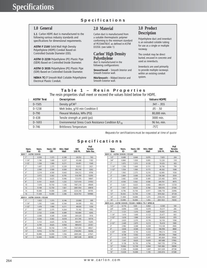
w w w . c a r l o n . c o m264
Specifications
3.0 Product DescriptionPolyethylene duct and innerductis an extruded coilable tubingfor use as a single or multipleraceway.
The conduit may be directburied, encased in concrete andused as innerducts.
Innerducts are used primarily to provide multiple racewayswithin an existing conduit system.
S p e c i f i c a t i o n s
2.0 MaterialCarlon duct is manufactured from a suitable thermoplastic polymerconforming to the minimum standardof PE334470E/C as defined in ASTMD3350. (see table 1)
Carlon® High DensityPolyethyleneduct is manufactured in the following configurations:
Smoothwall – Smooth Interior andSmooth Exterior wall.
Rib/Smooth – Ribbed Interior andSmooth Exterior wall.
1.0 General1.1 Carlon HDPE duct is manufactured to thefollowing various industry standards and specifications for dimensional requirements.
ASTM F 2160 Solid Wall High DensityPolyethylene (HDPE) Conduit Based onControlled Outside Diameter (OD).
ASTM D 2239 Polyethylene (PE) Plastic Pipe(SIDR) Based on Controlled Inside Diameter.
ASTM D 3035 Polyethylene (PE) Plastic Pipe(SDR) Based on Controlled Outside Diameter.
NEMA TC-7 Smooth Wall Coilable PolyethyleneElectrical Plastic Conduit.
T a b l e 1 – R e s i n P r o p e r t i e sThe resin properties shall meet or exceed the values listed below for HDPE.
ASTM Test Description Values HDPE
D-1505 Density g/CM3 .941 - .955
D-1238 Melt Index, g/10 min Condition E .05 - .50
D-790 Flexural Modulus, MPa (PSI) 80,000 min.
D-638 Tensile strength at yield (psi) 3000 min.
D-1693 Environmental Stress Crack Resistance Condition B,F10 96 hrs. min.
D-746 Brittleness Temperature -75˚C
S p e c i f i c a t i o n sPull
Nom. Nom. Nom. OD Min. Wall Wt/ TensileSize ID OD Wall 100 Ft. Safe lbs.
SDR 7 - ASTM D3035
1" 0.939 1.315 0.188 28.552 743
1-1/4" 1.186 1.660 0.237 45.448 1183
1-1/2' 1.358 1.900 0.271 59.491 1549
2" 1.697 2.375 0.339 93.012 2421
3" 2.500 3.500 0.500 202.140 5262
4" 3.214 4.500 0.643 334.212 8700
5" 3.972 5.562 0.795 510.709 13295
6" 4.733 6.625 0.946 723.976 18847
8" 6.161 8.625 1.232 1227.418 31953
10 7.678 10.750 1.536 1907.218 49649
12 9.108 12.750 1.821 2681.954 69818
14 10.000 14.000 2.000 3234.240 84195
16 11.428 16.000 2.286 4224.753 109980
SDR 9 - ASTM D3035 / F2160
1" 1.023 1.315 0.146 23.000 599
1-1/4" 1.292 1.660 0.184 36.599 953
1-1/2" 1.478 1.900 0.211 48.026 1250
2" 1.847 2.375 0.264 75.102 1955
3" 2.722 3.500 0.389 163.084 4245
4" 3.500 4.500 0.500 269.520 7016
5" 4.326 5.562 0.618 411.745 10719
6" 5.153 6.625 0.736 584.091 15205
8" 6.709 8.625 0.958 989.810 25767
10" 8.362 10.750 1.194 1537.593 40027
12" 9.916 12.750 1.417 2164.092 56336
14" 10.888 14.000 1.556 2609.340 67927
16" 12.444 16.000 1.778 3407.638 88709
PullNom. Nom. Nom. OD Min. Wall Wt/ TensileSize ID OD Wall 100 Ft. Safe lbs.
SDR 11 - ASTM D3035 / F2160
1/2" 0.688 0.840 0.076 7.825 204
3/4" 0.860 1.050 0.095 12.226 318
1" 1.075 1.315 0.120 19.325 503
1-1/4" 1.358 1.660 0.151 30.706 799
1-1/2" 1.554 1.900 0.173 40.262 1048
2" 1.943 2.375 0.216 62.845 1636
3" 2.864 3.500 0.318 136.360 3550
4" 3.682 4.500 0.409 225.483 5870
5" 4.550 5.562 0.506 344.761 8975
6" 5.421 6.625 0.602 488.619 12720
8" 7.057 8.625 0.784 828.416 21566
10" 8.796 10.750 0.977 1286.718 33496
12" 10.432 12.750 1.159 1810.362 47128
14" 11.454 14.000 1.273 2183.310 56837
16" 13.090 16.000 1.455 2851.923 74242
SDR 13.5 - ASTM D3035 / F2160 / NEMA TC-7 EPEC-B
1/2" 0.716 0.84 0.062 6.500 169
3/4" 0.894 1.050 0.078 10.217 266
1" 1.121 1.315 0.097 15.921 414
1-1/4" 1.414 1.660 0.123 25.477 663
1-1/2" 1.618 1.900 0.141 33.423 870
2" 2.023 2.375 0.176 52.155 1358
2-1/2" 2.449 2.875 0.213 76.410 1989
3" 2.982 3.500 0.259 113.120 2945
4" 3.834 4.500 0.333 186.994 4868
4-3/4" 4.084 4.750 0.333 198.213 5160
5" 4.738 5.562 0.412 285.934 7444
6" 5.643 6.625 0.491 405.869 10566
8" 7.347 8.625 0.639 687.688 17902
10" 9.158 10.750 0.796 1067.755 27796
12" 10.862 12.750 0.944 1501.882 39098
14" 11.926 14.000 1.037 1811.529 47158
16" 13.630 16.000 1.185 2365.816 61588
Requests for certifications must be requested at time of quote
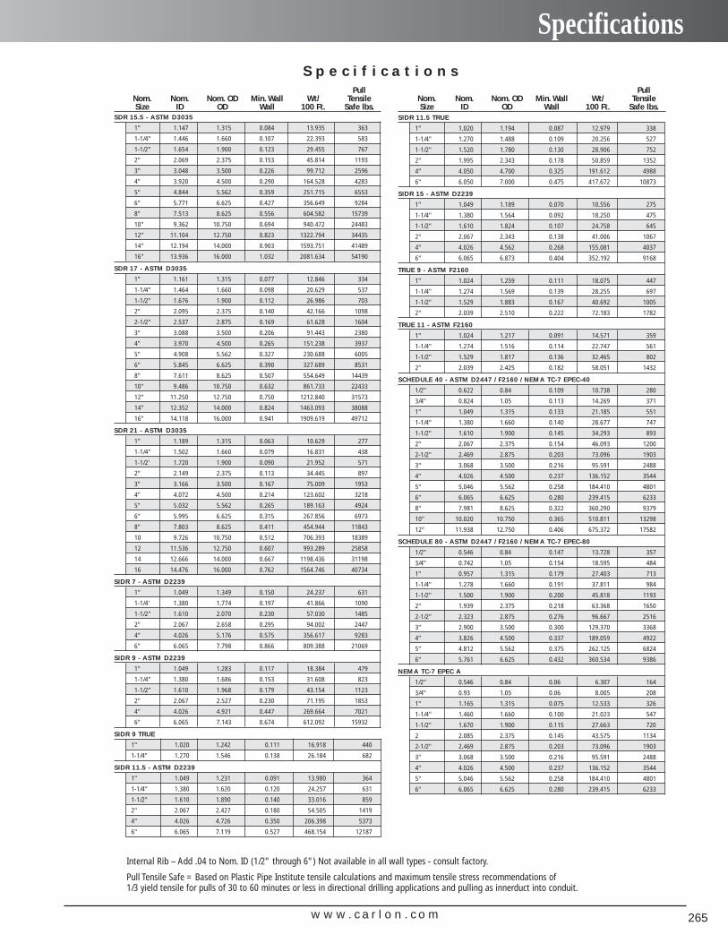
w w w . c a r l o n . c o m 265
SpecificationsS p e c i f i c a t i o n s
PullNom. Nom. Nom. OD Min. Wall Wt/ TensileSize ID OD Wall 100 Ft. Safe lbs.
PullNom. Nom. Nom. OD Min. Wall Wt/ TensileSize ID OD Wall 100 Ft. Safe lbs.
SIDR 11.5 TRUE
1" 1.020 1.194 0.087 12.979 338
1-1/4" 1.270 1.488 0.109 20.256 527
1-1/2" 1.520 1.780 0.130 28.906 752
2" 1.995 2.343 0.178 50.859 1352
4" 4.050 4.700 0.325 191.612 4988
6" 6.050 7.000 0.475 417.672 10873
SIDR 15 - ASTM D2239
1" 1.049 1.189 0.070 10.556 275
1-1/4" 1.380 1.564 0.092 18.250 475
1-1/2" 1.610 1.824 0.107 24.758 645
2" 2.067 2.343 0.138 41.006 1067
4" 4.026 4.562 0.268 155.081 4037
6" 6.065 6.873 0.404 352.192 9168
TRUE 9 - ASTM F2160
1" 1.024 1.259 0.111 18.075 447
1-1/4" 1.274 1.569 0.139 28.255 697
1-1/2" 1.529 1.883 0.167 40.692 1005
2" 2.039 2.510 0.222 72.183 1782
TRUE 11 - ASTM F2160
1" 1.024 1.217 0.091 14.571 359
1-1/4" 1.274 1.516 0.114 22.747 561
1-1/2" 1.529 1.817 0.136 32.465 802
2" 2.039 2.425 0.182 58.051 1432
SCHEDULE 40 - ASTM D2447 / F2160 / NEMA TC-7 EPEC-40
1/2" 0.622 0.84 0.109 10.738 280
3/4" 0.824 1.05 0.113 14.269 371
1" 1.049 1.315 0.133 21.185 551
1-1/4" 1.380 1.660 0.140 28.677 747
1-1/2" 1.610 1.900 0.145 34.293 893
2" 2.067 2.375 0.154 46.093 1200
2-1/2" 2.469 2.875 0.203 73.096 1903
3" 3.068 3.500 0.216 95.591 2488
4" 4.026 4.500 0.237 136.152 3544
5" 5.046 5.562 0.258 184.410 4801
6" 6.065 6.625 0.280 239.415 6233
8" 7.981 8.625 0.322 360.290 9379
10" 10.020 10.750 0.365 510.811 13298
12" 11.938 12.750 0.406 675.372 17582
SCHEDULE 80 - ASTM D2447 / F2160 / NEMA TC-7 EPEC-80
1/2" 0.546 0.84 0.147 13.728 357
3/4" 0.742 1.05 0.154 18.595 484
1" 0.957 1.315 0.179 27.403 713
1-1/4" 1.278 1.660 0.191 37.811 984
1-1/2" 1.500 1.900 0.200 45.818 1193
2" 1.939 2.375 0.218 63.368 1650
2-1/2" 2.323 2.875 0.276 96.667 2516
3" 2.900 3.500 0.300 129.370 3368
4" 3.826 4.500 0.337 189.059 4922
5" 4.812 5.562 0.375 262.125 6824
6" 5.761 6.625 0.432 360.534 9386
NEMA TC-7 EPEC A
1/2" 0.546 0.84 0.06 6.307 164
3/4" 0.93 1.05 0.06 8.005 208
1" 1.165 1.315 0.075 12.533 326
1-1/4" 1.460 1.660 0.100 21.023 547
1-1/2" 1.670 1.900 0.115 27.663 720
2 2.085 2.375 0.145 43.575 1134
2-1/2" 2.469 2.875 0.203 73.096 1903
3" 3.068 3.500 0.216 95.591 2488
4" 4.026 4.500 0.237 136.152 3544
5" 5.046 5.562 0.258 184.410 4801
6" 6.065 6.625 0.280 239.415 6233
SDR 15.5 - ASTM D3035
1" 1.147 1.315 0.084 13.935 363
1-1/4" 1.446 1.660 0.107 22.393 583
1-1/2" 1.654 1.900 0.123 29.455 767
2" 2.069 2.375 0.153 45.814 1193
3" 3.048 3.500 0.226 99.712 2596
4" 3.920 4.500 0.290 164.528 4283
5" 4.844 5.562 0.359 251.715 6553
6" 5.771 6.625 0.427 356.649 9284
8" 7.513 8.625 0.556 604.582 15739
10" 9.362 10.750 0.694 940.472 24483
12" 11.104 12.750 0.823 1322.794 34435
14" 12.194 14.000 0.903 1593.751 41489
16" 13.936 16.000 1.032 2081.634 54190
SDR 17 - ASTM D3035
1" 1.161 1.315 0.077 12.846 334
1-1/4" 1.464 1.660 0.098 20.629 537
1-1/2" 1.676 1.900 0.112 26.986 703
2" 2.095 2.375 0.140 42.166 1098
2-1/2" 2.537 2.875 0.169 61.628 1604
3" 3.088 3.500 0.206 91.443 2380
4" 3.970 4.500 0.265 151.238 3937
5" 4.908 5.562 0.327 230.688 6005
6" 5.845 6.625 0.390 327.689 8531
8" 7.611 8.625 0.507 554.649 14439
10" 9.486 10.750 0.632 861.733 22433
12" 11.250 12.750 0.750 1212.840 31573
14" 12.352 14.000 0.824 1463.093 38088
16" 14.118 16.000 0.941 1909.619 49712
SDR 21 - ASTM D3035
1" 1.189 1.315 0.063 10.629 277
1-1/4" 1.502 1.660 0.079 16.831 438
1-1/2' 1.720 1.900 0.090 21.952 571
2" 2.149 2.375 0.113 34.445 897
3" 3.166 3.500 0.167 75.009 1953
4" 4.072 4.500 0.214 123.602 3218
5" 5.032 5.562 0.265 189.163 4924
6" 5.995 6.625 0.315 267.856 6973
8" 7.803 8.625 0.411 454.944 11843
10 9.726 10.750 0.512 706.393 18389
12 11.536 12.750 0.607 993.289 25858
14 12.666 14.000 0.667 1198.436 31198
16 14.476 16.000 0.762 1564.746 40734
SIDR 7 - ASTM D2239
1" 1.049 1.349 0.150 24.237 631
1-1/4' 1.380 1.774 0.197 41.866 1090
1-1/2" 1.610 2.070 0.230 57.030 1485
2" 2.067 2.658 0.295 94.002 2447
4" 4.026 5.176 0.575 356.617 9283
6" 6.065 7.798 0.866 809.388 21069
SIDR 9 - ASTM D2239
1" 1.049 1.283 0.117 18.384 479
1-1/4" 1.380 1.686 0.153 31.608 823
1-1/2" 1.610 1.968 0.179 43.154 1123
2" 2.067 2.527 0.230 71.195 1853
4" 4.026 4.921 0.447 269.664 7021
6" 6.065 7.143 0.674 612.092 15932
SIDR 9 TRUE
1" 1.020 1.242 0.111 16.918 440
1-1/4" 1.270 1.546 0.138 26.184 682
SIDR 11.5 - ASTM D2239
1" 1.049 1.231 0.091 13.980 364
1-1/4" 1.380 1.620 0.120 24.257 631
1-1/2" 1.610 1.890 0.140 33.016 859
2" 2.067 2.427 0.180 54.505 1419
4" 4.026 4.726 0.350 206.398 5373
6" 6.065 7.119 0.527 468.154 12187
Internal Rib – Add .04 to Nom. ID (1/2" through 6") Not available in all wall types - consult factory.
Pull Tensile Safe = Based on Plastic Pipe Institute tensile calculations and maximum tensile stress recommendations of 1/3 yield tensile for pulls of 30 to 60 minutes or less in directional drilling applications and pulling as innerduct into conduit.
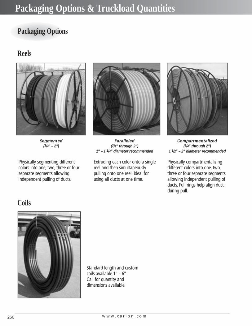
w w w . c a r l o n . c o m266
Packaging Options & Truckload Quantities
Compartmentalized(3/4" through 2")
1 1/2" – 2" diameter recommended
Paralleled(3/4" through 2")
1" – 1 1/4" diameter recommended
Segmented(3/4" – 2")
Packaging Options
Physically segmenting different colors into one, two, three or fourseparate segments allowing independent pulling of ducts.
Physically compartmentalizingdifferent colors into one, two,three or four separate segmentsallowing independent pulling ofducts. Full rings help align duct during pull.
Extruding each color onto a singlereel and then simultaneouslypulling onto one reel. Ideal forusing all ducts at one time.
Standard length and custom coils available 1" - 6".Call for quantity and dimensions available.
Reels
Coils
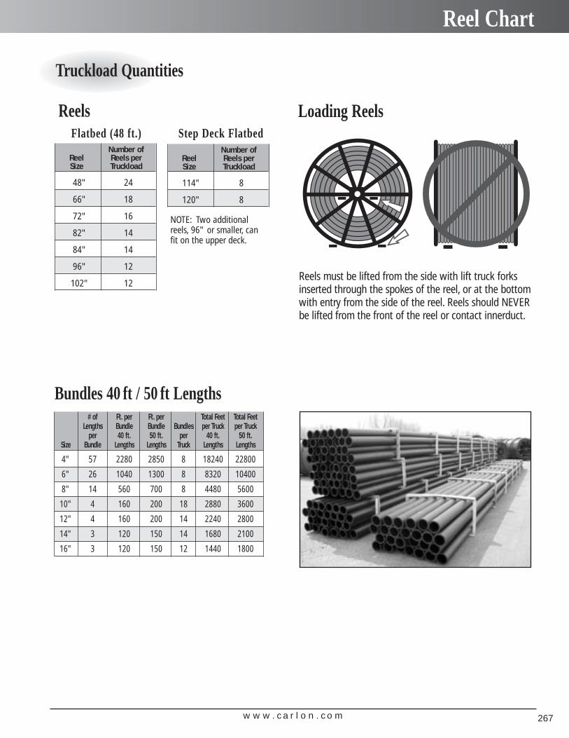
w w w . c a r l o n . c o m 267
Reel Chart
Flatbed (48 ft.) Step Deck Flatbed
NOTE: Two additionalreels, 96" or smaller, canfit on the upper deck.
Number of Reel Reels per Size Truckload
48" 24
66" 18
72" 16
82" 14
84" 14
96" 12
102" 12
Number of Reel Reels per Size Truckload
114" 8
120" 8
Truckload Quantities
# of Ft. per Ft. per Total Feet Total FeetLengths Bundle Bundle Bundles per Truck per Truck
per 40 ft. 50 ft. per 40 ft. 50 ft.Size Bundle Lengths Lengths Truck Lengths Lengths
4" 57 2280 2850 8 18240 22800
6" 26 1040 1300 8 8320 10400
8" 14 560 700 8 4480 5600
10" 4 160 200 18 2880 3600
12" 4 160 200 14 2240 2800
14" 3 120 150 14 1680 2100
16" 3 120 150 12 1440 1800
Reels
Bundles 40 ft / 50 ft Lengths
Reels must be lifted from the side with lift truck forksinserted through the spokes of the reel, or at the bottomwith entry from the side of the reel. Reels should NEVERbe lifted from the front of the reel or contact innerduct.
Loading Reels
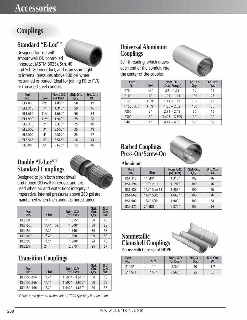
w w w . c a r l o n . c o m268
Accessories
Couplings
Universal AluminumCouplingsSelf-threading, which drawseach end of the conduit intothe center of the coupler.
Double “E-Loc”®
Standard CouplingsDesigned to join both smoothwall and ribbed OD wall innerduct and are used when air and water-tight integrity is imperative. Internal pressures above 200 psi aremaintained when the conduit is unrestrained.
Barbed CouplingsPress-On/Screw-On
Standard “E-Loc”®
Designed for use with smoothwall OD controlled innerduct (ASTM 3035), Sch. 40and Sch. 80 innerduct, and is pressure tightto internal pressures above 200 psi whenrestrained or buried. Ideal for joining PE to PVCor threaded steel conduit.
NonmetallicClamshell CouplingsFor use with Corrugated HDPE
Part Nom. O.D. Std. Ctn. Std. Ctn.No. Size (of Duct) Qty. Wt.E144F 1" 1.34" 30 1.7
E144GT 11/4" 1.565" 25 2
Part Nom. O.D. Std. Ctn. Std. Ctn.No. Size (of Duct) Qty. Wt.
BS1.315 1" SDR 1.315" 100 16
BS1.194 1" True 11 1.194" 100 16
BS1.488 11/4" True 11 1.488" 100 16
BS1.660 11/4" SDR 1.660" 100 16
BS1.900 11/2" SDR 1.900" 100 24
BS2.375 2" SDR 2.375" 100 34
Aluminum
Part Nom. O.D. Std. Ctn. Std. Ctn.No. Size (Duct Range) Qty. Wt.
P75 3/4" .91 – 1.08 10 12P100 1" 1.21 – 1.41 100 25P125 1 1/4" 1.44 – 1.68 100 28P150CPLR 1 1/2" 1.80 – 2.02 100 35P200 2" 2.31 – 2.48 50 19P300 3" 3.495 – 3.505 12 10P400 4" 4.41 – 4.65 12 12
Part Nom. O.D. Std. Ctn. Std. Ctn.No. Size (of Duct) Qty. Wt.
EL1.050 3/4" 1.050" 50 19EL1.315 1" 1.315" 50 46EL1.660 11/4" 1.660" 50 34EL1.900 11/2" 1.900" 25 28EL2.375 2" 2.375" 25 40EL3.500 3" 3.500" 25 48EL4.500 4" 4.500" 25 67EL5.563 5" 5.563" 16 44EL6.00 6" 6.625" 12 40
“E-Loc” is a registered trademark of ETCO Specialty Products, Inc.
Transition CouplingsStd. Std.
Part Nom. O.D. Ctn. Ctn.No. Size (of Duct) Qty. Wt.
DEL150-154 11/4" 1.500" - 1.540" 50 58DEL150-166 11/4" 1.500" - 1.660" 50 58DEL154-166 11/4" 1.540" - 1.660" 50 58
Std. Std.Part Nom. O.D. Ctn. Ctn.No. Size (of Duct) Qty. Wt.
DEL131 1" 1.315" 50 63DEL150 11/4" True 1.500" 50 58DEL154 11/4" 1.540" 50 58DEL166 11/4" 1.660" 50 53DEL190 11/2" 1.900" 24 43DEL237 2" 2.375" 25 57
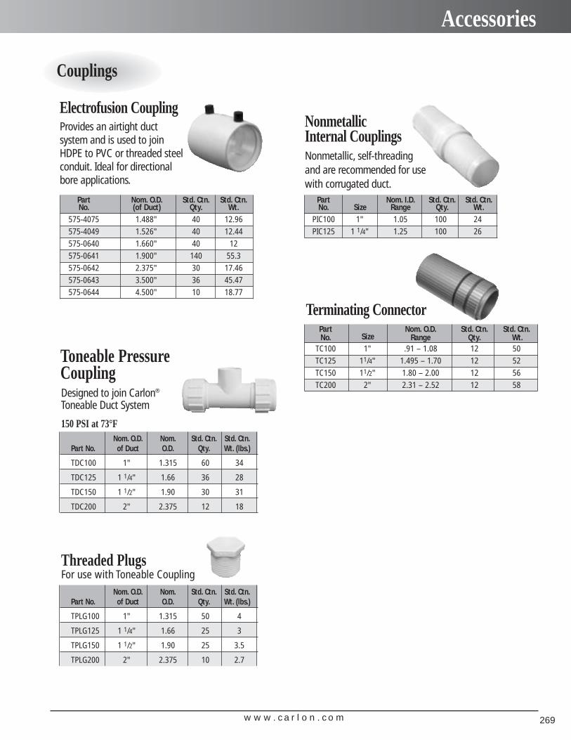
w w w . c a r l o n . c o m 269
Accessories
Couplings
Terminating Connector
Electrofusion CouplingProvides an airtight duct system and is used to joinHDPE to PVC or threaded steelconduit. Ideal for directionalbore applications.
Nonmetallic Internal CouplingsNonmetallic, self-threading and are recommended for usewith corrugated duct.
Part Nom. I.D. Std. Ctn. Std. Ctn.No. Size Range Qty. Wt.
PIC100 1" 1.05 100 24PIC125 1 1/4" 1.25 100 26
Part Nom. O.D. Std. Ctn. Std. Ctn.No. (of Duct) Qty. Wt.
575-4075 1.488" 40 12.96575-4049 1.526" 40 12.44575-0640 1.660" 40 12575-0641 1.900" 140 55.3575-0642 2.375" 30 17.46575-0643 3.500" 36 45.47575-0644 4.500" 10 18.77
Part Nom. O.D. Std. Ctn. Std. Ctn.No. Size Range Qty. Wt.
TC100 1" .91 – 1.08 12 50TC125 11/4" 1.495 – 1.70 12 52TC150 11/2" 1.80 – 2.00 12 56TC200 2" 2.31 – 2.52 12 58
Toneable PressureCoupling
Nom. O.D. Nom. Std. Ctn. Std. Ctn.Part No. of Duct O.D. Qty. Wt. (lbs.)
TDC100 1" 1.315 60 34
TDC125 1 1/4" 1.66 36 28
TDC150 1 1/2" 1.90 30 31
TDC200 2" 2.375 12 18
Designed to join Carlon®
Toneable Duct System
150 PSI at 73°F
Nom. O.D. Nom. Std. Ctn. Std. Ctn.Part No. of Duct O.D. Qty. Wt. (lbs.)
TPLG100 1" 1.315 50 4
TPLG125 1 1/4" 1.66 25 3
TPLG150 1 1/2" 1.90 25 3.5
TPLG200 2" 2.375 10 2.7
Threaded Plugs For use with Toneable Coupling
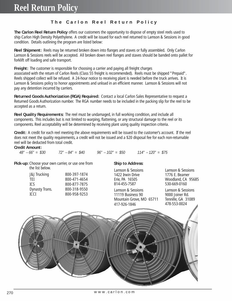
w w w . c a r l o n . c o m270
Reel Return Policy
The Carlon Reel Return Policy offers our customers the opportunity to dispose of empty steel reels used to ship Carlon High Density Polyethylene. A credit will be issued for each reel returned to Lamson & Sessions in goodcondition. Details outlining the program are listed below:
Reel Shipment: Reels may be returned broken down into flanges and staves or fully assembled. Only CarlonLamson & Sessions reels will be accepted. All broken down reel flanges and staves should be banded onto pallet forforklift off loading and safe transport.
Freight: The customer is responsible for choosing a carrier and paying all freight charges associated with the return of Carlon Reels (Class 55 freight is recommended). Reels must be shipped "Prepaid".Reels shipped collect will be refused. A 24-hour notice to receiving plant is needed before the truck arrives. It isLamson & Sessions policy to honor appointments and unload in an efficient manner. Lamson & Sessions will notpay any detention incurred by carriers.
Returned Goods Authorization (RGA) Required: Contact a local Carlon Sales Representative to request aReturned Goods Authorization number. The RGA number needs to be included in the packing slip for the reel to beaccepted as a return.
Reel Quality Requirements: The reel must be undamaged, in full working condition, and include all components. This includes but is not limited to warping, flattening, or any structural damage to the reel or its components. Reel acceptability will be determined by receiving plant using quality inspection criteria.
Credit: A credit for each reel meeting the above requirements will be issued to the customer’s account. If the reeldoes not meet the quality requirements, a credit will not be issued and a $20 disposal fee for each non-returnablereel will be deducted from total credit.Credit Amount:
48" – 66" = $30 72" – 84" = $40 96" – 102" = $50 114" – 120" = $75
T h e C a r l o n R e e l R e t u r n P o l i c y
J&J Trucking 800-397-1874TEI 800-471-4654ICS 800-877-7875Dynasty Trans. 800-318-9550ICCI 800-958-9253
Pick-up: Choose your own carrier, or use one fromthe list below. Lamson & Sessions
1422 Irwin DriveErie, PA 16505814-455-7587
Lamson & Sessions11119 Business 90Mountain Grove, MO 65711417-926-1846
Lamson & Sessions1776 E. BeamerWoodland, CA 95685530-669-0160
Lamson & Sessions9000 Joiner Rd.Tennille, GA 31089478-553-0024
Ship to Address:
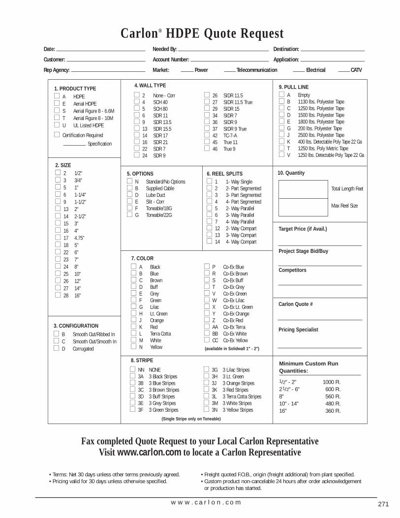
w w w . c a r l o n . c o m 271
Carlon® HDPE Quote RequestDate: Needed By: Destination:
Customer: Account Number: Application:
Rep Agency: Market: Power Telecommunication Electrical CATV
Minimum Custom RunQuantities:
1/2" - 2" 1000 Ft.21/2" - 6" 600 Ft.8" 560 Ft.10" - 14" 480 Ft.16" 360 Ft.
Fax completed Quote Request to your Local Carlon Representative Visit www.carlon.com to locate a Carlon Representative
1. PRODUCT TYPE� A HDPE� E Aerial HDPE� S Aerial Figure 8 - 6.6M� T Aerial Figure 8 - 10M� U UL Listed HDPE
� Certification RequiredSpecification
� NN NONE� 3A 3 Black Stripes� 3B 3 Blue Stripes� 3C 3 Brown Stripes� 3D 3 Buff Stripes� 3E 3 Grey Stripes� 3F 3 Green Stripes
� 3G 3 Lilac Stripes� 3H 3 Lt. Green� 3J 3 Orange Stripes� 3K 3 Red Stripes� 3L 3 Terra Cotta Stripes� 3M 3 White Stripes� 3N 3 Yellow Stripes
9. PULL LINE� A Empty� B 1130 lbs. Polyester Tape� C 1250 lbs. Polyester Tape� D 1500 lbs. Polyester Tape� E 1800 lbs. Polyester Tape� G 200 lbs. Polyester Tape� J 2500 lbs. Polyester Tape� K 400 lbs. Detectable Poly Tape 22 Ga� T 1250 lbs. Poly Metric Tape� V 1250 lbs. Detectable Poly Tape 22 Ga
10. Quantity
Total Length Feet
Max Reel Size
Carlon Quote #
Pricing Specialist
5. OPTIONS� N Standard/No Options� B Supplied Cable� D Lube Duct� E Slit - Corr� F Toneable/18G� G Toneable/22G
� A Black� B Blue� C Brown� D Buff� E Grey� F Green� G Lilac� H Lt. Green� J Orange� K Red� L Terra Cotta� M White� N Yellow
� P Co-Ex Blue� R Co-Ex Brown� S Co-Ex Buff� T Co-Ex Grey� V Co-Ex Green� W Co-Ex Lilac� X Co-Ex Lt. Green� Y Co-Ex Orange� Z Co-Ex Red� AA Co-Ex Terra� BB Co-Ex White� CC Co-Ex Yellow
6. REEL SPLITS� 1 1- Way Single� 2 2- Part Segmented� 3 3- Part Segmented� 4 4- Part Segmented� 5 2- Way Parallel� 6 3- Way Parallel� 7 4- Way Parallel� 12 2- Way Compart� 13 3- Way Compart� 14 4- Way Compart
� 2 None - Corr� 4 SCH 40� 5 SCH 80� 6 SDR 11� 9 SDR 13.5� 13 SDR 15.5� 14 SDR 17� 16 SDR 21� 22 SDR 7� 24 SDR 9
� 26 SIDR 11.5� 27 SIDR 11.5 True� 29 SIDR 15� 34 SIDR 7� 36 SIDR 9� 37 SIDR 9 True� 42 TC-7-A� 45 True 11� 46 True 9
3. CONFIGURATION
� B Smooth Out/Ribbed In� C Smooth Out/Smooth In� D Corrugated
2. SIZE� 2 1/2"� 3 3/4"� 5 1"� 6 1-1/4"� 9 1-1/2"� 13 2"� 14 2-1/2"� 15 3"� 16 4"� 17 4.75"� 18 5"� 22 6"� 23 7"� 24 8"� 25 10"� 26 12"� 27 14"� 28 16"
Target Price (if Avail.)
Project Stage Bid/Buy
Competitors
• Terms: Net 30 days unless other terms previously agreed. • Freight quoted F.O.B., origin (freight additional) from plant specified.• Pricing valid for 30 days unless otherwise specified. • Custom product non-cancelable 24 hours after order acknowledgement
or production has started.
4. WALL TYPE
(available in Solidwall 1" - 2")
7. COLOR
8. STRIPE
(Single Stripe only on Toneable)

w w w . c a r l o n . c o m272
w w w . c a r l o n . c o m 273
Carlon® Cable and Installation Accessories
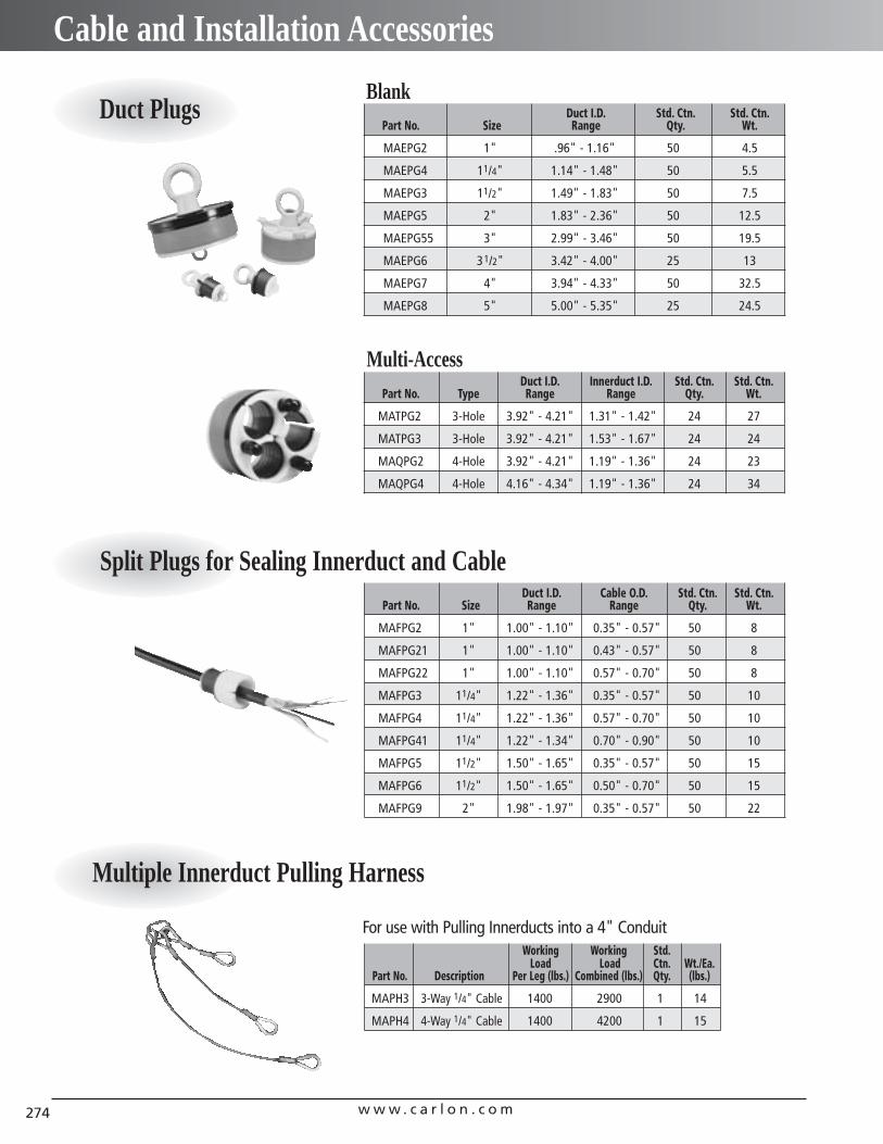
w w w . c a r l o n . c o m274
Cable and Installation Accessories
Duct Plugs
Split Plugs for Sealing Innerduct and Cable Duct I.D. Cable O.D. Std. Ctn. Std. Ctn.
Part No. Size Range Range Qty. Wt.
MAFPG2 1" 1.00" - 1.10" 0.35" - 0.57" 50 8
MAFPG21 1" 1.00" - 1.10" 0.43" - 0.57" 50 8
MAFPG22 1" 1.00" - 1.10" 0.57" - 0.70" 50 8
MAFPG3 11/4" 1.22" - 1.36" 0.35" - 0.57" 50 10
MAFPG4 11/4" 1.22" - 1.36" 0.57" - 0.70" 50 10
MAFPG41 11/4" 1.22" - 1.34" 0.70" - 0.90" 50 10
MAFPG5 11/2" 1.50" - 1.65" 0.35" - 0.57" 50 15
MAFPG6 11/2" 1.50" - 1.65" 0.50" - 0.70" 50 15
MAFPG9 2" 1.98" - 1.97" 0.35" - 0.57" 50 22
Multiple Innerduct Pulling Harness
Working Working Std.Load Load Ctn. Wt./Ea.
Part No. Description Per Leg (lbs.) Combined (lbs.) Qty. (lbs.)
MAPH3 3-Way 1/4" Cable 1400 2900 1 14
MAPH4 4-Way 1/4" Cable 1400 4200 1 15
Duct I.D. Innerduct I.D. Std. Ctn. Std. Ctn.Part No. Type Range Range Qty. Wt.
MATPG2 3-Hole 3.92" - 4.21" 1.31" - 1.42" 24 27
MATPG3 3-Hole 3.92" - 4.21" 1.53" - 1.67" 24 24
MAQPG2 4-Hole 3.92" - 4.21" 1.19" - 1.36" 24 23
MAQPG4 4-Hole 4.16" - 4.34" 1.19" - 1.36" 24 34
Multi-Access
Duct I.D. Std. Ctn. Std. Ctn.Part No. Size Range Qty. Wt.
MAEPG2 1" .96" - 1.16" 50 4.5
MAEPG4 11/4" 1.14" - 1.48" 50 5.5
MAEPG3 11/2" 1.49" - 1.83" 50 7.5
MAEPG5 2" 1.83" - 2.36" 50 12.5
MAEPG55 3" 2.99" - 3.46" 50 19.5
MAEPG6 31/2" 3.42" - 4.00" 25 13
MAEPG7 4" 3.94" - 4.33" 50 32.5
MAEPG8 5" 5.00" - 5.35" 25 24.5
Blank
For use with Pulling Innerducts into a 4" Conduit
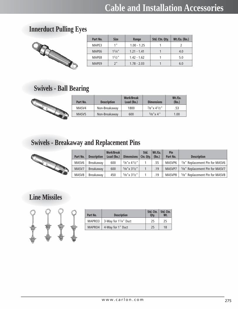
w w w . c a r l o n . c o m 275
Cable and Installation Accessories
Innerduct Pulling Eyes
Swivels - Ball BearingWork/Break Wt./Ea.
Part No. Description Load (lbs.) Dimensions (lbs.)
MASV4 Non-Breakaway 1800 7/8"x 41/2" .53
MASV5 Non-Breakaway 600 5/8"x 4" 1.00
Work/Break Std. Wt./Ea. PinPart No. Description Load (lbs.) Dimensions Ctn. Qty. (lbs.) Part No. Description
MASV6 Breakaway 600 7/8"x 41/2" 1 .55 MASVP6 7/8" Replacement Pin for MASV6
MASV7 Breakaway 600 5/8"x 31/2" 1 .19 MASVP7 5/8" Replacement Pin for MASV7
MASV8 Breakaway 450 5/8"x 31/2" 1 .19 MASVP8 5/8" Replacement Pin for MASV8
Swivels - Breakaway and Replacement Pins
Part No. Size Range Std. Ctn. Qty. Wt./Ea. (lbs.)
MAPE3 1" 1.00 - 1.25 1 2
MAPE6 11/4" 1.21 - 1.41 1 4.0
MAPE8 11/2" 1.42 - 1.62 1 5.0
MAPE9 2" 1.78 - 2.03 1 6.0
Line Missiles
Std. Ctn. Std. Ctn.Part No. Description Qty. Wt.
MAPRO3 3-Way for 11/4" Duct 25 25
MAPRO4 4-Way for 1" Duct 25 18
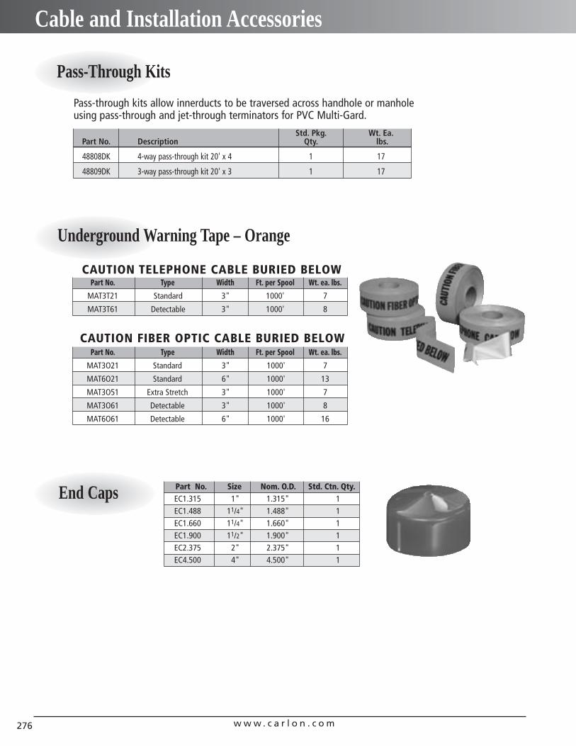
w w w . c a r l o n . c o m276
Cable and Installation Accessories
End Caps Part No. Size Nom. O.D. Std. Ctn. Qty.EC1.315 1" 1.315" 1EC1.488 11/4" 1.488" 1EC1.660 11/4" 1.660" 1EC1.900 11/2" 1.900" 1EC2.375 2" 2.375" 1EC4.500 4" 4.500" 1
Underground Warning Tape – Orange
Part No. Type Width Ft. per Spool Wt. ea. lbs.
MAT3T21 Standard 3" 1000' 7
MAT3T61 Detectable 3" 1000' 8
CAUTION TELEPHONE CABLE BURIED BELOW
Part No. Type Width Ft. per Spool Wt. ea. lbs.
MAT3O21 Standard 3" 1000' 7
MAT6O21 Standard 6" 1000' 13
MAT3O51 Extra Stretch 3" 1000' 7
MAT3O61 Detectable 3" 1000' 8
MAT6O61 Detectable 6" 1000' 16
CAUTION FIBER OPTIC CABLE BURIED BELOW
Std. Pkg. Wt. Ea.Part No. Description Qty. lbs.
48808DK 4-way pass-through kit 20' x 4 1 17
48809DK 3-way pass-through kit 20' x 3 1 17
Pass-through kits allow innerducts to be traversed across handhole or manholeusing pass-through and jet-through terminators for PVC Multi-Gard.
Pass-Through Kits
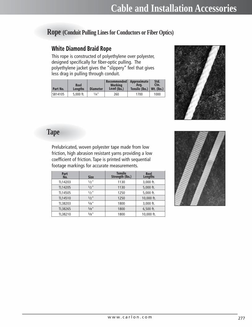
w w w . c a r l o n . c o m 277
Cable and Installation Accessories
Rope (Conduit Pulling Lines for Conductors or Fiber Optics)
Tape
Prelubricated, woven polyester tape made from low friction, high abrasion resistant yarns providing a lowcoefficient of friction. Tape is printed with sequentialfootage markings for accurate measurements.
Part Tensile ReelNo. Size Strength (lbs.) Lengths
TL14203 1/2" 1130 3,000 ft.TL14205 1/2" 1130 5,000 ft.TL14505 1/2" 1250 5,000 ft.TL14510 1/2" 1250 10,000 ft.TL38203 5/8" 1800 3,000 ft.TL38265 5/8" 1800 6,500 ft.TL38210 5/8" 1800 10,000 ft.
This rope is constructed of polyethylene over polyester,designed specifically for fiber-optic pulling. The polyethylene jacket gives the “slippery” feel that givesless drag in pulling through conduit.
White Diamond Braid Rope
Recommended Approximate Std.Reel Working Avg. Ctn.
Part No. Lengths Diameter Load (lbs.) Tensile (lbs.) Wt. (lbs.)SB14105 5,000 ft. 1/4" 260 1700 1000
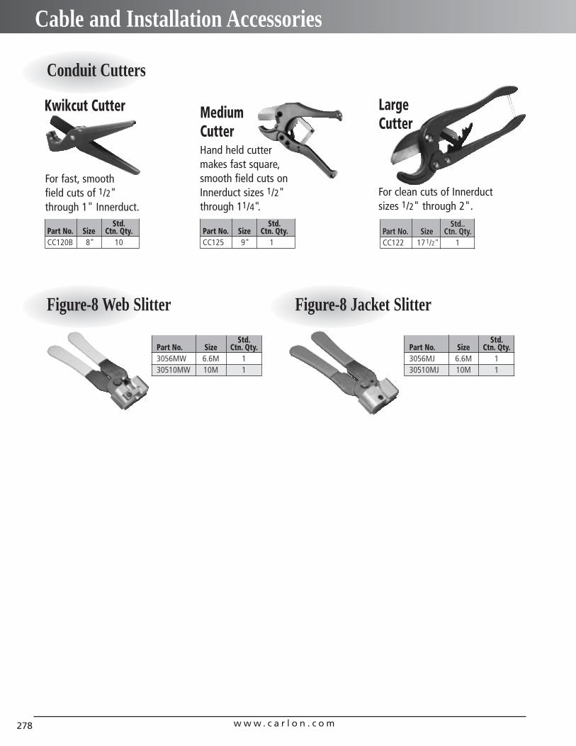
w w w . c a r l o n . c o m278
Cable and Installation Accessories
Std.Part No. Size Ctn. Qty.CC120B 8" 10
Std.Part No. Size Ctn. Qty.3056MW 6.6M 130510MW 10M 1
Std.Part No. Size Ctn. Qty.CC125 9" 1
Std..Part No. Size Ctn. Qty.CC122 17 1/2" 1
Hand held cutter makes fast square,smooth field cuts on Innerduct sizes 1/2" through 11/4".
For clean cuts of Innerductsizes 1/2" through 2".
For fast, smooth field cuts of 1/2" through 1" Innerduct.
Kwikcut Cutter MediumCutter
LargeCutter
Conduit Cutters
Figure-8 Web Slitter
Std.Part No. Size Ctn. Qty.3056MJ 6.6M 130510MJ 10M 1
Figure-8 Jacket Slitter

w w w . c a r l o n . c o m 279
Notes

w w w . c a r l o n . c o m280
Notes

w w w . c a r l o n . c o m 281
Notes
LIMITED WARRANTY/DEFECTIVE PRODUCTS/SHORT COUNTS
Carlon warrants to its distributors that its products conform to all product specifications contained in the contract of sale and, using Carlon product specifications as a standard, are free from defects in material and manufacture as of the date they are shipped by Carlon. This warranty covers Carlondistributors only.
IF A DISTRIBUTOR BELIEVES THAT IT HAS DISCOVERED A DEFECT IN MATERIAL OR MANUFACTURE INANY PRODUCT COVERED BY THIS WARRANTY OR IF THE DISTRIBUTOR DISCOVERS A SHORT COUNTIN ANY SHIPMENT, THE DISTRIBUTOR MUST NOTIFY CARLON, IN WRITING, WITHIN SIXTY (60) DAYSOF RECEIPT OF THE GOODS TO WHICH THE CLAIM RELATES, OR IN ANY EVENT WITHIN SEVENTY (70)DAYS OF THE DATE THAT THE GOODS WERE SHIPPED BY Carlon. Carlon will provide replacementgoods to meet any short count for which it receives timely notice, but may require verification of anysuch claim. Defective goods should be shipped to Carlon, freight prepaid, and be in accordance withCarlon defective goods policy which requires prior approval by an authorized Carlon Manager. Carlonliability for breach of this warranty shall be limited to replacement of any goods that Carlon finds tobe defective with an equivalent amount of goods, or at Carlon sole option, refund of the purchaseprice. Claims that are not made within the warranty period (i.e., within seventy (70) days of shipment)shall be deemed waived.
CARLON SHALL NOT BE LIABLE FOR ANY INCIDENTAL OR CONSEQUENTIAL DAMAGES CAUSED BY BREACH OF THIS WARRANTY. THIS EXCLUSION APPLIES WHETHER SUCH DAMAGES ARE SOUGHTBASED ON BREACH OF WARRANTY BREACH OF CONTRACT, NEGLIGENCE, STRICT LIABILITY IN TORTOR ANY OTHER LEGAL THEORY. THIS WARRANTY DOES NOT APPLY TO CLAIMS FOR PERSONALINJURY BY A THIRD PARTY. THIS WARRANTY DOES NOT COVER DAMAGE IN SHIPMENT. CLAIMS FORDAMAGE IN SHIPMENT SHOULD BE MADE TO THE CARRIER IN ACCORDANCE WITH THE TERMS OFTHE SHIPPING AGREEMENTS.
THIS WARRANTY IS IN LIEU OF ALL OTHER WARRANTIES, WHETHER EXPRESS, IMPLIED, OR ORAL,INCLUDING THE IMPLIED WARRANTY OF MERCHANTABILITY, ANY IMPLIED WARRANTY OF FITNESSFOR A PARTICULAR PURPOSE, AND ANY IMPLIED WARRANTIES OTHERWISE ARISING FROM ACOURSE OF DEALING OR TRADE.
Inside Sales:Region Phone Fax
NORTHEAST (610) 759-6760 (610) 759-9138SOUTHEAST (800) 3CARLON (216) 766-6444CENTRAL (800) 3CARLON (216) 766-6444WEST (916) 666-1681 (530) 669-0173
CARLON 50M SP 07/03© Lamson & Sessions 2003
In USA, contact:25701 Science Park Drive ❚ Cleveland, Ohio 44122 1-800-3-CARLON (1-800-322-7566) ❚ In Ohio, (216) 464-3400Fax: (216) 766-6444TDD/Hearing Impaired Access (216) 831-5918www.carlon.com
In Canada, contact:c/o Multimodal Logistics 415 Traders Boulevard EastMississauga, Ontario ❚ Canada L4Z 1P2(905) 755-1262 ❚ (888) 269-9902Fax: (905) 755-1265 ❚ (888) 229-8622