Embed Size (px)
Citation preview

23240 C hagrin Bl vd Suite 405 Cleveland, OH 44122 216- 464- 3400 www.primeconduit.com
PV-MOLD®
Nonmetallic Pole Riser System
Standard Duty
Heavy Duty Schedule 40
Extra Heavy Duty Schedule 80
Vented Boots
Adapters
Couplings
Backing Plates

23240 C hagrin Bl vd Suite 405 Cleveland, OH 44122 216- 464- 3400 www.primeconduit.com 2
PV Mold® Nonmetallic Pole Riser System
Prime Conduit PV-Mold is a nonmetallic pole riser system designed to protect communications power cable installed on poles.
Features:
Designed in accordance with NEMA TC-19
specifications. Ultraviolet, cold temperature and corrosive
atmosphere resistant. Schedule 40 wall meets Schedule 80 PVC conduit
impact requirements per NEMA TC-19. No grounding required.
Belled end fits over each added section or conduit. Requires no maintenance.
PV-Mold acts as an insulator against electrical shock. Interchangeable parts and accessories to match the
needs of specific requirements. Flanged overall length, including bell is 10 Feet.
Standard Duty
Part Number
Size Std. Qty.
Std. Qty. W t. (lbs.)
A B C H Depth of
Bell (min.) Impact @ 0C 20 lb.
Tup (ft.-lbs.) Impact @ 23C 20 lb.
Tup (ft.-lbs.)
59208N 1" 175 635 0.100" 1-5/16" 2-3/8" 1-5/16" 2" 40 150
59211N 2" 100 540 0.100" 2-3/8" 4-1/2" 2-3/8" 2" 100 190
59213N 3" 40 465 0.150" 3-1/2" 6" 3-1/2" 3" 110 220
59215N 4" 35 495 0.150" 4-1/2" 6-1/2" 4-1/2" 4" 110 220
59216N 5" 35 605 0.150" 5-1/2" 7-1/2" 5-1/2" 4" 110 220
Heavy Duty Schedule 40
Part Number
Size Std. Qty.
Std. Qty. W t. (lbs.)
A B C H Depth of
Bell (min.) Impact @ 0C 20 lb.
Tup (ft.-lbs.)
Impact @ 23C
20 lb. Tup (ft.-lbs.)
59010N 1-1/2" 165 950 0.145" 1-29/32" 3-1/2" 1-29/32" 2" 100 300
59011N 2" 100 815 0.154" 2-3/8" 4-1/2" 2-3/8" 2" 150 300
59013N 3" 40 660 0.216" 3-1/2" 6" 3-1/2" 3" 150 525
59015N 4" 35 765 0.237" 4-1/2" 6-1/2" 4-1/2" 4" 260 525
59016N 5" 35 1020 0.258" 5-1/2" 7-1/2" 5-1/2" 4" 260 525
59017N 6" 15 585 0.280" 6-5/8" 8-3/4" 6-5/8" 5" 260 525
Extra Heavy Duty Schedule 80
Part Number Size
Std. Qty.
Std. Qty. W t. (lbs.) A B C H
Depth of Bell (min.)
Impact @ 0C 75 lb. Tup (ft.-lbs.)
59411N 2" 100 1145 0.218" 2-3/8" 4-1/2" 2-3/8" 2" 150
59413N 3" 40 910 0.300" 3-1/2" 6" 3-1/2" 3" 260
Steel U-Guard required
grounding, strapping, and does not have
belled ends.
PV-Mold has belled ends,
flanged design, and does
not require grounding.
Mounting hole slots are ¾” length x 5/16” width. There are 7 mounting holes, per side, per 10 f oot length.

23240 C hagrin Bl vd Suite 405 Cleveland, OH 44122 216- 464- 3400 www.primeconduit.com 3
PV Mold® Boots, Adapters, and Fittings
Polyethylene Vented Boots and Adapters
1. A field cut may be needed to accommodate different boot or adapter to Prime Conduit PV-Mold size combinations.
2. Recommendation: 2 sets of mounting holes per boot/fitting. To add mounting holes, use a 3/8" dril l bit an d drill out where needed.
3. When 3" or smaller conduit is being used, it’s recommended that the bottom (largest section) of the boot or adapter section be buried 2" to 3" below ground surface.
Vented Boots Part
Number Size Std. Qty.
Std. Qty. W t. (lbs.)
E938JR 2” x 6” 4 13.5
E938NT 4” x 8” 4 21.0
E938NRR 4” x 6” 6 26.4
E938PRR 5” x 6” 6 23.2
Adapters Part
Number Size Std. Qty.
Std. Qty. W t. (lbs.)
E939JN 2” x 4” 8 10.0
E939NR 4” x 6” 6 11.7
E939NRT 4’ x 6” 3 14.0
Duct to Riser Fitting Part
Number Size Std. Qty.
Std. Qty. W t. (lbs.)
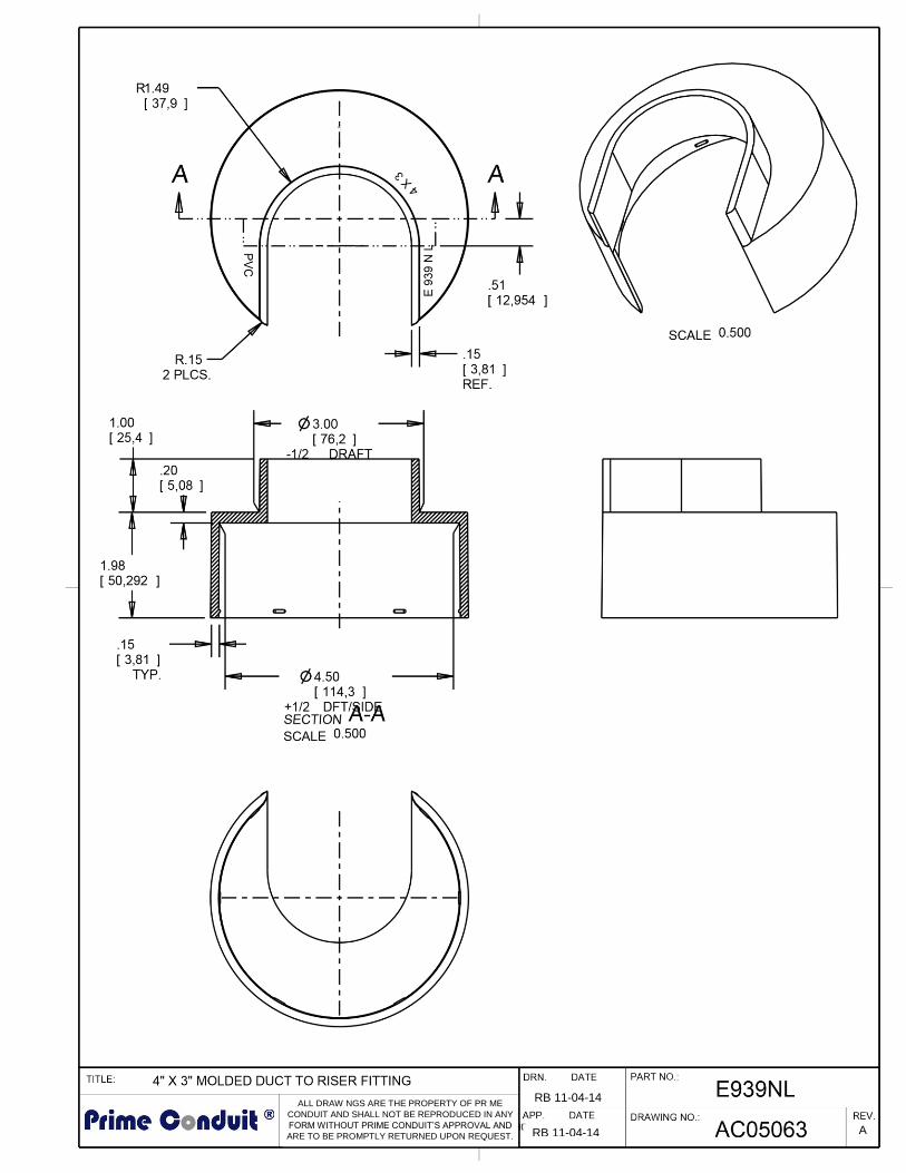
E939NL 4” x 3” 15 5.6
C-Style Backing Plate – 10’ Long Part
Number Size Std. Qty.
Std. Ctn. W t. (lbs.)
59111P 2” 1 1.4
59113P 3” 1 1.5
59115P 4” 1 3.0
59116P 5” 1 3.1
59117P 6” 1 4.2
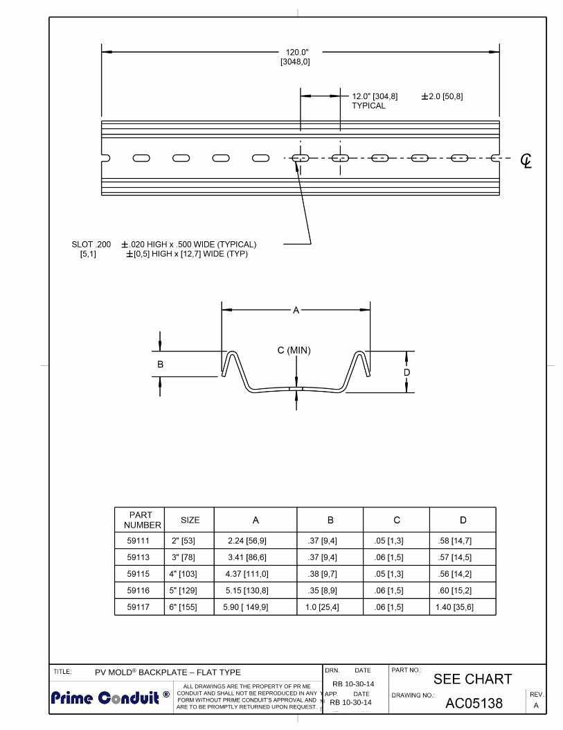
Flat-Style Backing Plate – 10’ Long Part
Number Size Std. Qty.
Std. Ctn. W t. (lbs.)
59111 2” 1 1.4
59113 3” 1 2.0
59115 4” 1 3.0
59116 5” 1 3.7
59117 6” 1 4.1
E939JN E939NR E939NRT
E938PRR E938NRR E938NT E938JR

23240 C hagrin Bl vd Suite 405 Cleveland, OH 44122 216- 464- 3400 www.primeconduit.com 4
PV Mold® Installation Instructions
Installation is easy with PV-Mold Pole Risers: 1. Install ventilator or duct to riser fittings at the
base of the pole.
2. Nail backing plate sections to the surface of the pole. Three nail holes are provided in each
section. Place the “U” sections over the cable and backing plate, with belled end at the bottom, and
attach using 1/4" lag bolts.
PV-Mold Adapters
E939JN To transition from 4" Conduit to 2" PV-Mold: Place Adapter ov er conduit, attach to pole using the top and bottom mounting holes, place PV-Mold ov er
top section of Adapter and secure PV-Mold to pole.
To transition from 4" Conduit to 3" PV-Mold: Measure 6.3" up f rom bottom (large end) of adapter and cut. Assemble to pole as described above.
To transition from 3" Conduit to 2" PV-Mold*: Measure 4.75" up f rom bottom (large end) of adapter and cut. Assemble to pole as described above.
E939NR To transition from 5" Conduit to 4" PV-Mold: Place Adapter ov er conduit, attach to pole using the top and bottom mounting holes, place PV-Mold ov er top section of Adapter and secure PV-Mold to pole.
To transition from 6" Conduit to 5" PV-Mold: Measure 7.25" up f rom bottom (large end) of adapter and cut. Assemble to pole as described above.
To transition from 5" Conduit to 5" PV-Mold* Measure 4.5" down f rom the top of adapter and cut. Assemble to pole as described above. *For these transitions it is not necessary to cut the Adapter if desired. If the Adapter is not modified, it is recommended that the bottom 3" of the Adapter be buried below grade.
E939NRT To transition from 6" Conduit to 4" PV-Mold: Place Adapter ov er conduit and attach to pole using the top and bottom mounting holes. Place PV-Mold
ov er top section of Adapter and secure PV-Mold to pole.
To transition from 6" Conduit to 5" PV-Mold: Measure 5.25" down f rom the top of the adapter and cut. Assemble to pole as described above.
To transition from 6" Conduit to 6" PV-Mold: Measure 9.5" up f rom the bottom of the adapter and cut. Assemble to pole as described above.
Flanged
Exclusiv e Bell End For easy and quick installation.
(No additional coupler required.)
10' Lengths Safe and light for easy handling during
installation.
Backing Plate Provides cable isolation from the pole.
Duct to riser fitting Adapts duct to PV-Mold.
Ventilator Fitting Used for a “chimney” effect to cool cable and increase ampacity
Did you know…
PV Mold does not have a fire rating or
classification. It is not permitted to be used inside of a building.
PV Mold is not UL or ETL listed. PV Mold meets and/or exceeds the requirements of NEMA TC-19.
23240 Chagrin Blvd Suite 405 Cleveland, OH 44122 216-464-3400 www.primeconduit.com © 2017 Prime Conduit, Inc. 5
PV Mold® Installation Instructions
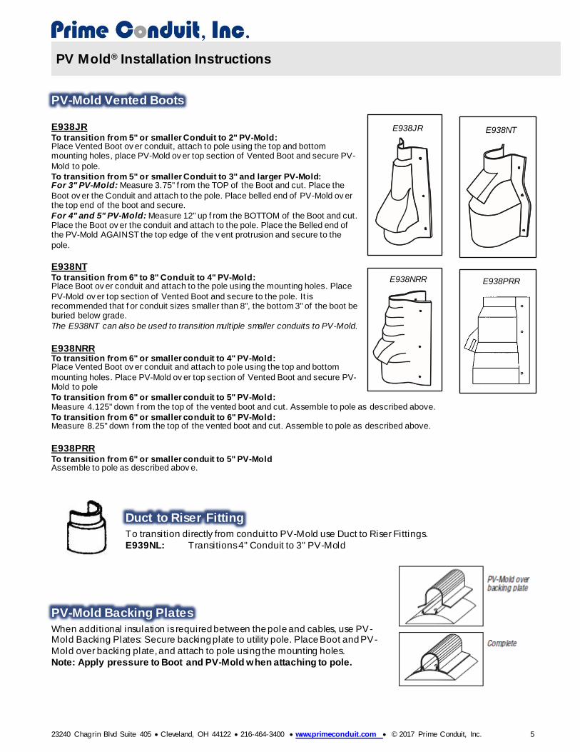
PV-Mold Vented Boots
E938JR To transition from 5" or smaller Conduit to 2" PV-Mold: Place Vented Boot ov er conduit, attach to pole using the top and bottom mounting holes, place PV-Mold ov er top section of Vented Boot and secure PV-
Mold to pole.
To transition from 5" or smaller Conduit to 3" and larger PV-Mold: For 3" PV-Mold: Measure 3.75" f rom the TOP of the Boot and cut. Place the
Boot ov er the Conduit and attach to the pole. Place belled end of PV-Mold ov er the top end of the boot and secure.
For 4" and 5" PV-Mold: Measure 12" up f rom the BOTTOM of the Boot and cut. Place the Boot ov er the conduit and attach to the pole. Place the Belled end of the PV-Mold AGAINST the top edge of the v ent protrusion and secure to the
pole.
E938NT To transition from 6" to 8" Conduit to 4" PV-Mold: Place Boot ov er conduit and attach to the pole using the mounting holes. Place
PV-Mold ov er top section of Vented Boot and secure to the pole. It is recommended that f or conduit sizes smaller than 8", the bottom 3" of the boot be buried below grade.
The E938NT can also be used to transition multiple smaller conduits to PV-Mold.
E938NRR To transition from 6" or smaller conduit to 4" PV-Mold: Place Vented Boot ov er conduit and attach to pole using the top and bottom
mounting holes. Place PV-Mold ov er top section of Vented Boot and secure PV-Mold to pole
To transition from 6" or smaller conduit to 5" PV-Mold: Measure 4.125" down f rom the top of the vented boot and cut. Assemble to pole as described above.
To transition from 6" or smaller conduit to 6" PV-Mold: Measure 8.25" down f rom the top of the vented boot and cut. Assemble to pole as described above. E938PRR To transition from 6" or smaller conduit to 5" PV-Mold Assemble to pole as described abov e.
Duct to Riser Fitting
To transition directly from conduit to PV-Mold use Duct to Riser Fittings.
E939NL: Transitions 4" Conduit to 3" PV-Mold
PV-Mold Backing Plates
When additional insulation is required between the pole and cables, use PV-Mold Backing Plates: Secure backing plate to utility pole. Place Boot and PV-
Mold over backing plate, and attach to pole using the mounting holes.
Note: Apply pressure to Boot and PV-Mold when attaching to pole.
E938JR
E938NRR E938PRR
E938NT

4 [61]
SEE CHARTS
AC04614 B
PV MOLD (POLE RISERS)(R)
RB 11-04-2014
RB 11-04-2014

RB 10-30-2014
RB 10-30-2014
See ChartAC04153 D
PV-MOLD VENTED BOOT(R)

RB 10-30-2014
RB 10-30-2014
E938NRRAC04392 B
PV MOLD VENTED BOOT - 6 INCH(R)

ALL DRAWINGS ARE THE PROPERTY OF PRIME
CONDUIT AND SHALL NOT BE REPRODUCED N ANY
FORM WITHOUT PR ME CONDUIT’S APPROVAL AND
ARE TO BE PROMPTLY RETURNED UPON REQUEST.
RB 10-30-14
RB 10-30-14 A

ALL DRAW NGS ARE THE PROPERTY OF PR ME CONDUIT
AND SHALL NOT BE REPRODUCED N ANY FORM
WITHOUT PRIME CONDUIT’S APPROVAL AND ARE TO BE
PROMPTLY RETURNED UPON REQUEST. C
RB 10-30-14
RB 10-30-14
PV-Mold® Adapter

ALL DRAWINGS ARE THE PROPERTY OF PR ME CONDUIT
AND SHALL NOT BE REPRODUCED IN ANY FORM
WITHOUT PR ME CONDUIT’S APPROVAL AND ARE TO BE
PROMPTLY RETURNED UPON REQUEST.
RB 10-30-14
RB 10-30-14 A
3” TO 6” PV MOLD® BOOT
ALL DRAW NGS ARE THE PROPERTY OF PR ME
CONDUIT AND SHALL NOT BE REPRODUCED IN ANY
FORM WITHOUT PRIME CONDUIT’S APPROVAL AND
ARE TO BE PROMPTLY RETURNED UPON REQUEST.
RB 11-04-14
RB 11-04-14 A

RB 10-30-2014
RB 10-30-2014
SEE CHARTAC05137 A
PV MOLD BACKPLATE C - TYPE(R)
ALL DRAWINGS ARE THE PROPERTY OF PR ME
CONDUIT AND SHALL NOT BE REPRODUCED IN ANY
FORM WITHOUT PRIME CONDUIT’S APPROVAL AND
ARE TO BE PROMPTLY RETURNED UPON REQUEST.
RB 10-30-14
RB 10-30-14 A
PV MOLD® BACKPLATE – FLAT TYPE