Embed Size (px)
Citation preview
Carbon storage capacity analysis through the integrated reservoir modelling on Caswell Fan, Upper Campanian,
Browse Basin, Australia
Liuqi Wang, Rick Causebrook & Chris Consoli
Geoscience Australia
CO2 Geological Storage and Technology
Summer School of CAGSSanya City, Hainan Island, PRC
Aug 21st – Aug 25th 2010
Objective
Static Reservoir Modelling
Upscaling of Static Reservoir Model
Initial Reservoir Condition
Fluid Property and Relative Permeability
Injectivity Analysis
Simulation result and analysis
Summary
Outline
1 Objective
To assess the characterized and practical CO2 storage
capacity of Caswell Fan, Upper Campanian, Browse Basin,
through static and dynamic reservoir modelling
Stage 1:
Characterized CO2 Storage Capacity Assessment through Static Reservoir Modelling Using GOCADTM
Stage 2:
Practical CO2 Storage Capacity Analysis through Dynamic Reservoir Simulation Using CMG-GEMTM
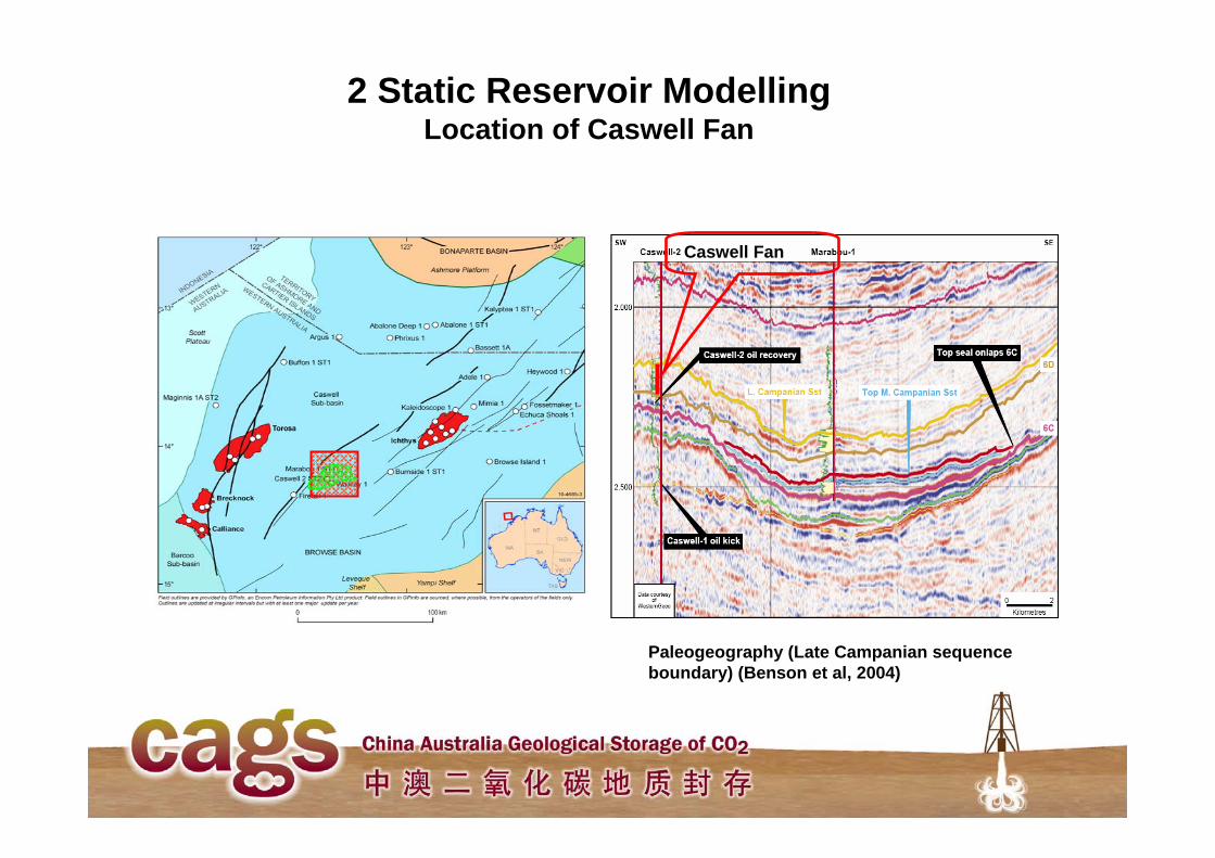
2 Static Reservoir ModellingLocation of Caswell Fan
Paleogeography (Late Campanian sequence boundary) (Benson et al, 2004)
Caswell Fan
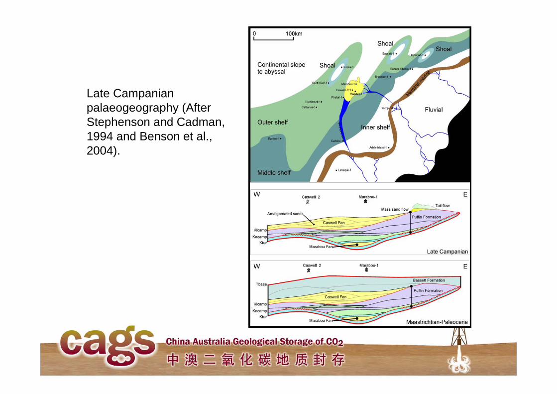
Late Campanianpalaeogeography (After Stephenson and Cadman, 1994 and Benson et al., 2004).

2 Static Reservoir ModellingWorkflow
Characterized CO2 Storage Capacity Potential
Basin Geology
Well Log InterpretationSeismic InterpretationSedimentology &
Sequence Stratigraphy
Velocity Modelling & Time-Depth
Conversion3D Grid
Construction
Reservoir Heterogeneity &
Upscaling
Reservoir Modelling
Pore Volume
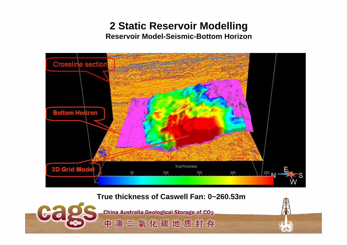
True thickness of Caswell Fan: 0~260.53m
2 Static Reservoir ModellingReservoir Model-Seismic-Bottom Horizon
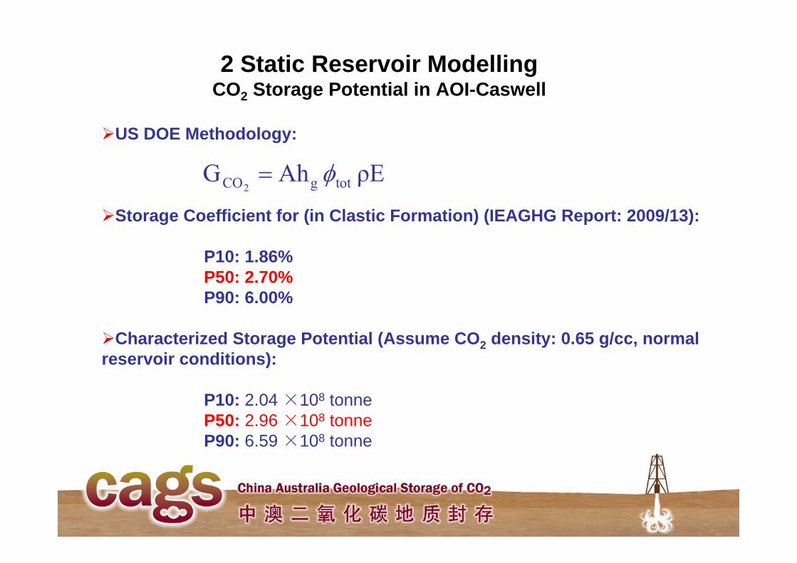
2 Static Reservoir ModellingCO2 Storage Potential in AOI-Caswell
US DOE Methodology:
Storage Coefficient for (in Clastic Formation) (IEAGHG Report: 2009/13):
P10: 1.86%P50: 2.70%P90: 6.00%
Characterized Storage Potential (Assume CO2 density: 0.65 g/cc, normal reservoir conditions):
P10: 2.04 ×10⁸ tonneP50: 2.96 ×10⁸ tonneP90: 6.59 ×10⁸ tonne
ρEAhG totgCO2
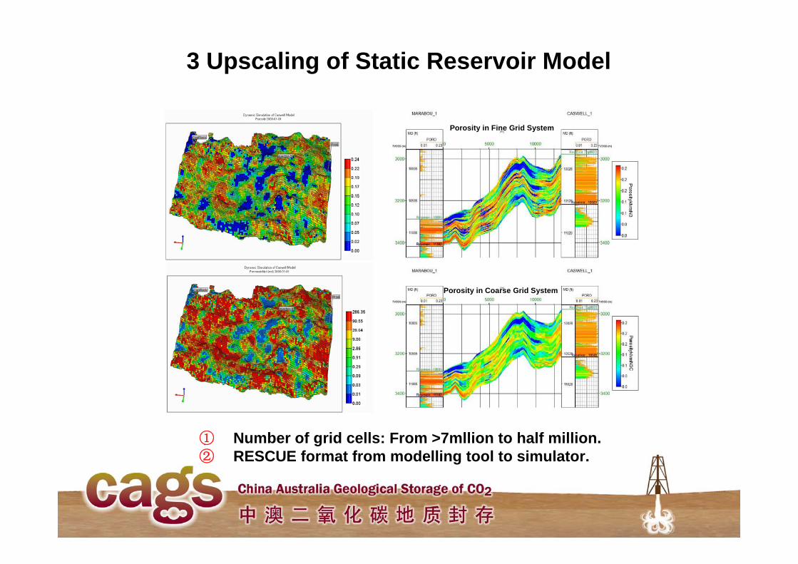
3 Upscaling of Static Reservoir Model
① Number of grid cells: From >7mllion to half million.② RESCUE format from modelling tool to simulator.
Porosity in Fine Grid System
Porosity in Coarse Grid System
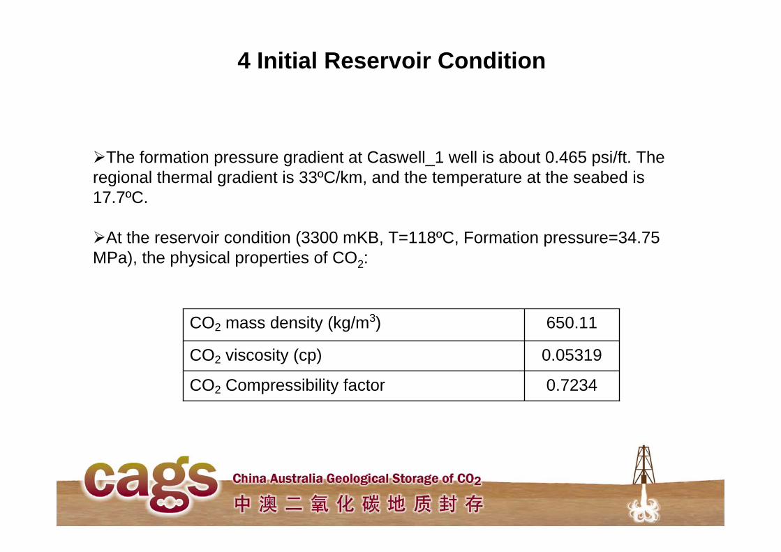
4 Initial Reservoir Condition
The formation pressure gradient at Caswell_1 well is about 0.465 psi/ft. The regional thermal gradient is 33ºC/km, and the temperature at the seabed is 17.7ºC.
At the reservoir condition (3300 mKB, T=118ºC, Formation pressure=34.75 MPa), the physical properties of CO2:
0.7234CO2 Compressibility factor
0.05319CO2 viscosity (cp)
650.11CO2 mass density (kg/m3)
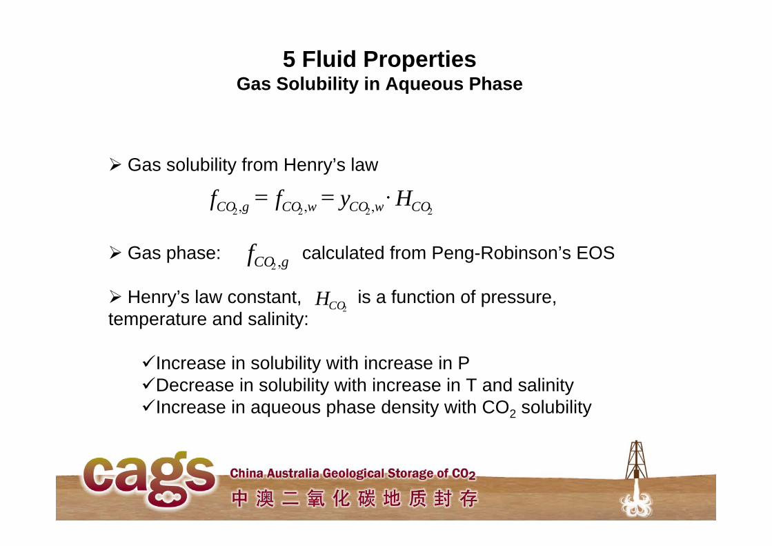
5 Fluid PropertiesGas Solubility in Aqueous Phase
Gas solubility from Henry’s law
Gas phase: calculated from Peng-Robinson’s EOS
Henry’s law constant, is a function of pressure, temperature and salinity:
Increase in solubility with increase in P Decrease in solubility with increase in T and salinityIncrease in aqueous phase density with CO2 solubility
2222 ,,, COwCOwCOgCO Hyff
gCOf ,2
2COH
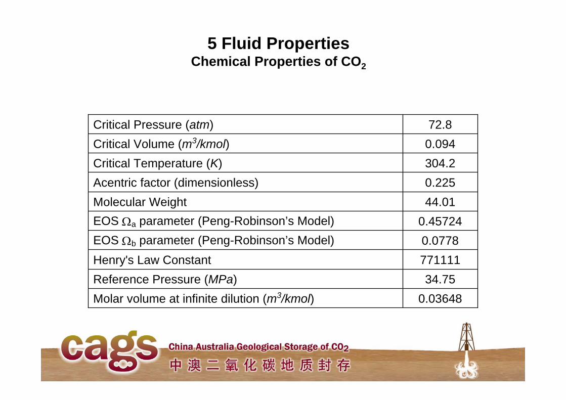
5 Fluid PropertiesChemical Properties of CO2
0.03648Molar volume at infinite dilution (m3/kmol)34.75Reference Pressure (MPa)
771111Henry's Law Constant0.0778EOS b parameter (Peng-Robinson’s Model) 0.45724EOS a parameter (Peng-Robinson’s Model)
44.01Molecular Weight0.225Acentric factor (dimensionless)304.2Critical Temperature (K)0.094Critical Volume (m3/kmol)72.8Critical Pressure (atm)
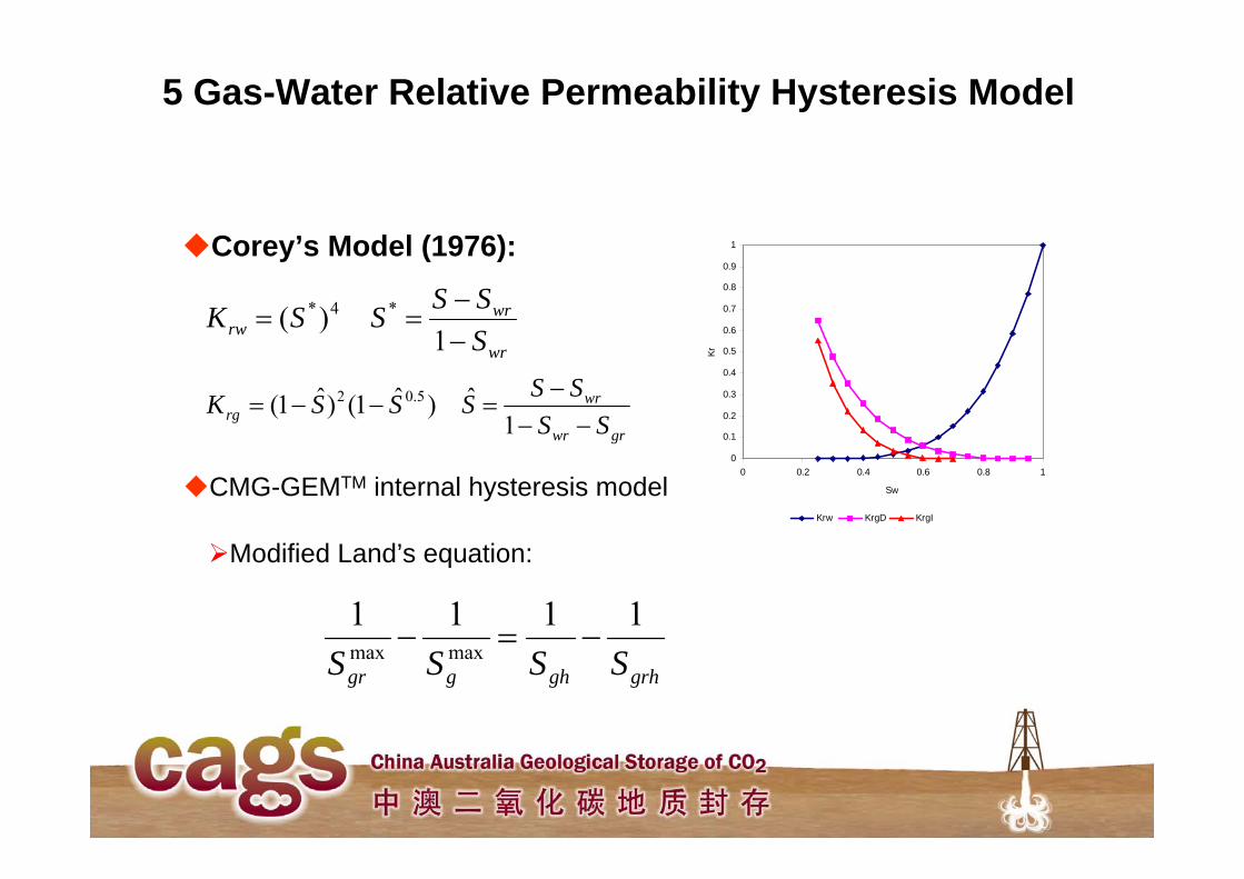
Corey’s Model (1976):
5 Gas-Water Relative Permeability Hysteresis Model
wr
wrrw S
SSSSK
1
)( *4*
grwr
wrrg SS
SSSSSK
1ˆ)ˆ1()ˆ1( 5.02
0
0.1
0.2
0.3
0.4
0.5
0.6
0.7
0.8
0.9
1
0 0.2 0.4 0.6 0.8 1
Sw
Kr
Krw KrgD KrgI
CMG-GEMTM internal hysteresis model
grhghggr SSSS1111
maxmax
Modified Land’s equation:
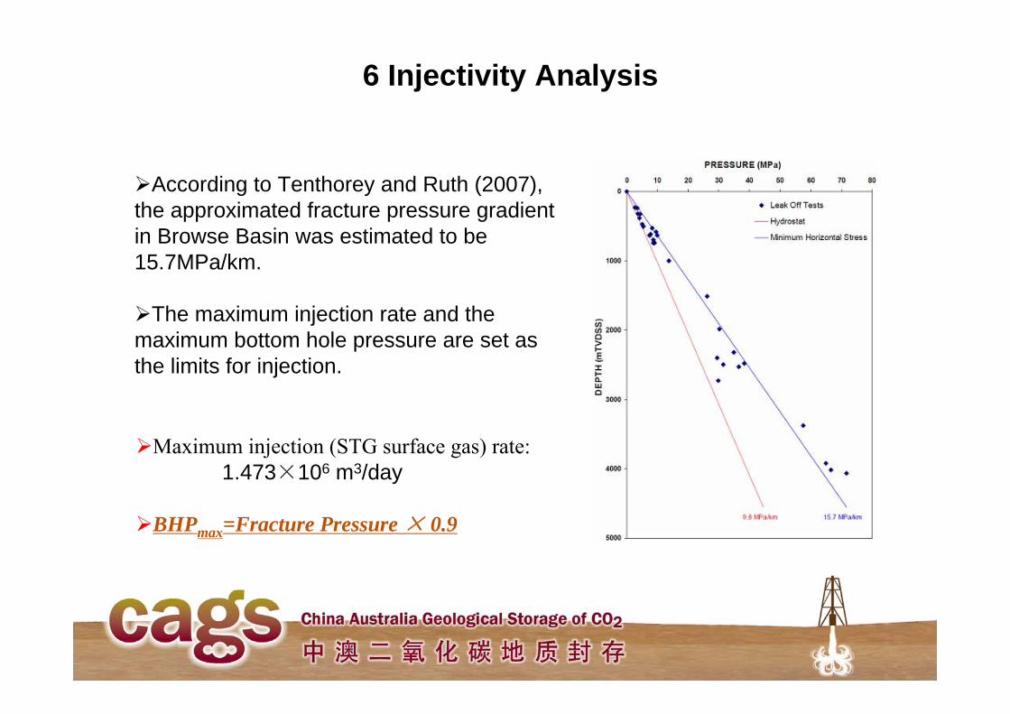
6 Injectivity Analysis
Maximum injection (STG surface gas) rate:1.473×10⁶ m3/day
BHPmax=Fracture Pressure × 0.9
According to Tenthorey and Ruth (2007), the approximated fracture pressure gradient in Browse Basin was estimated to be 15.7MPa/km.
The maximum injection rate and the maximum bottom hole pressure are set as the limits for injection.
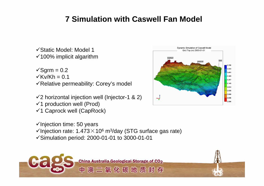
7 Simulation with Caswell Fan Model
Static Model: Model 1100% implicit algarithm
Sgrm = 0.2Kv/Kh = 0.1Relative permeability: Corey’s model
2 horizontal injection well (Injector-1 & 2)1 production well (Prod)1 Caprock well (CapRock)
Injection time: 50 yearsInjection rate: 1.473×10⁶ m3/day (STG surface gas rate)Simulation period: 2000-01-01 to 3000-01-01
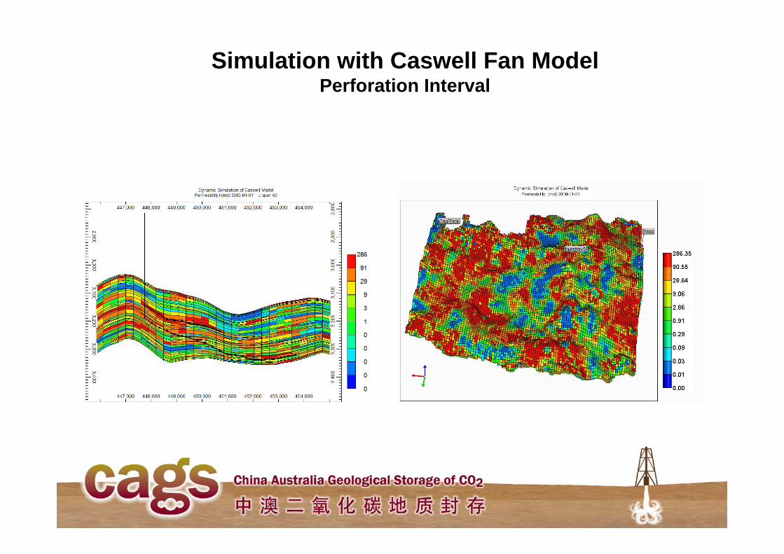
Simulation with Caswell Fan ModelPerforation Interval
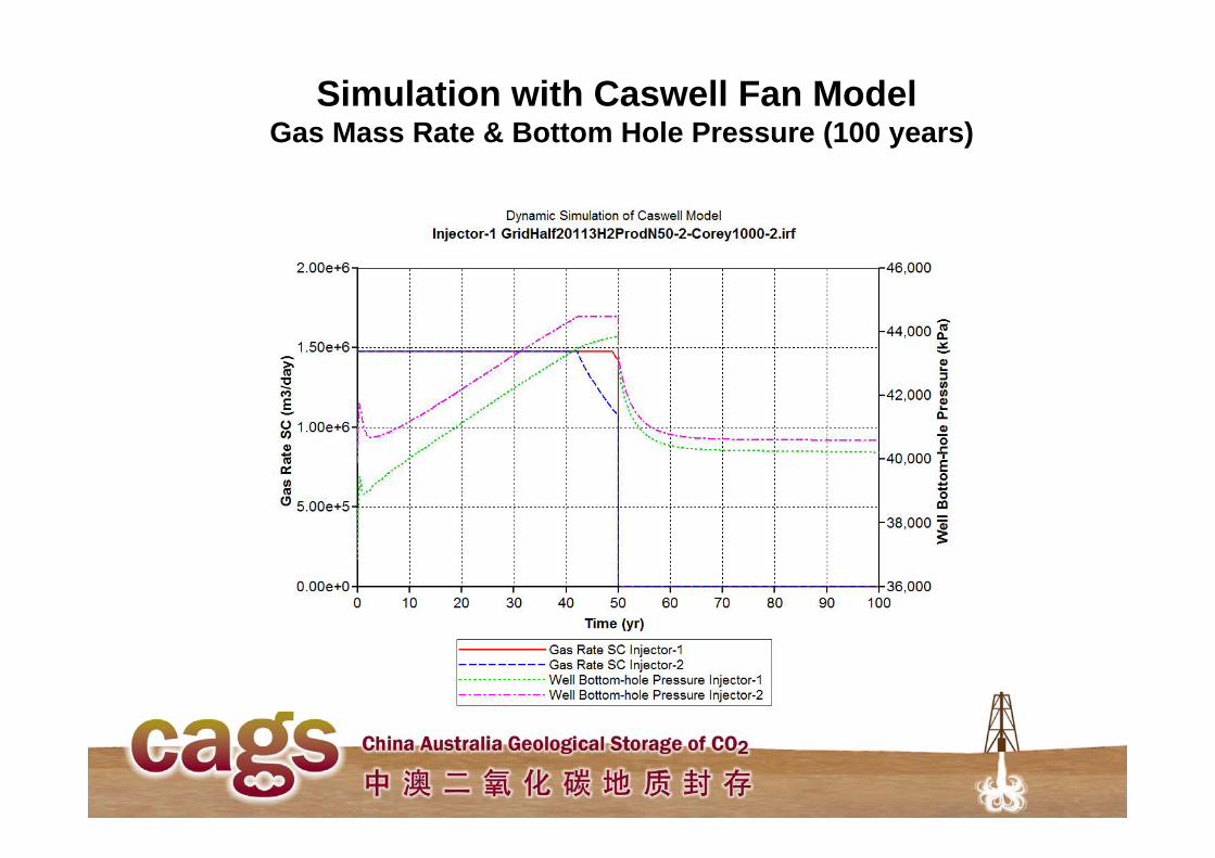
Simulation with Caswell Fan ModelGas Mass Rate & Bottom Hole Pressure (100 years)
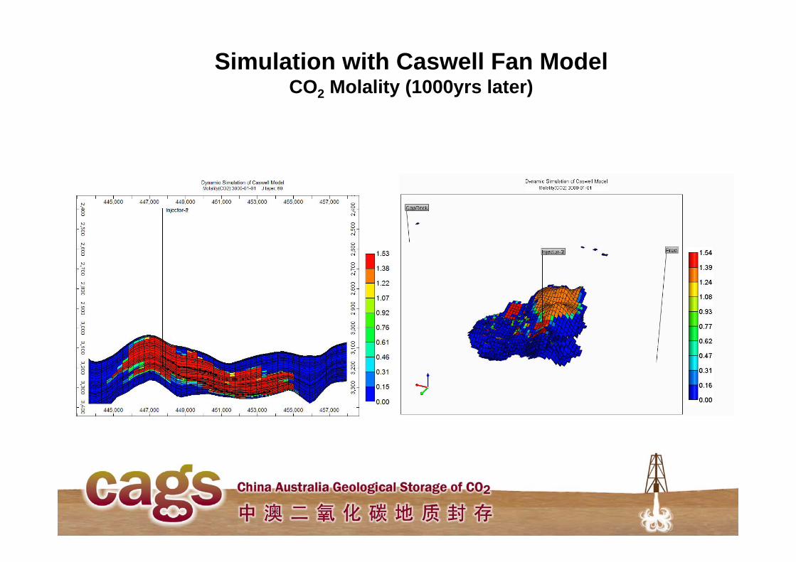
Simulation with Caswell Fan ModelCO2 Molality (1000yrs later)
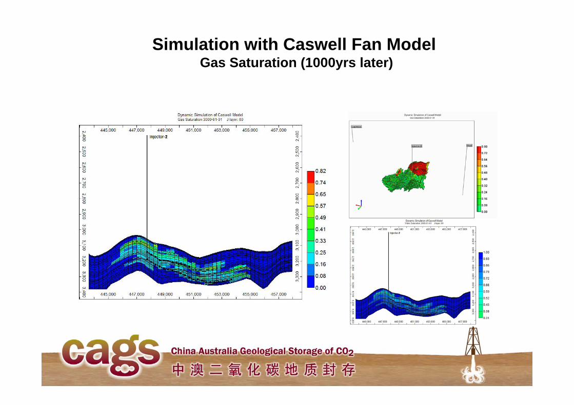
Simulation with Caswell Fan ModelGas Saturation (1000yrs later)
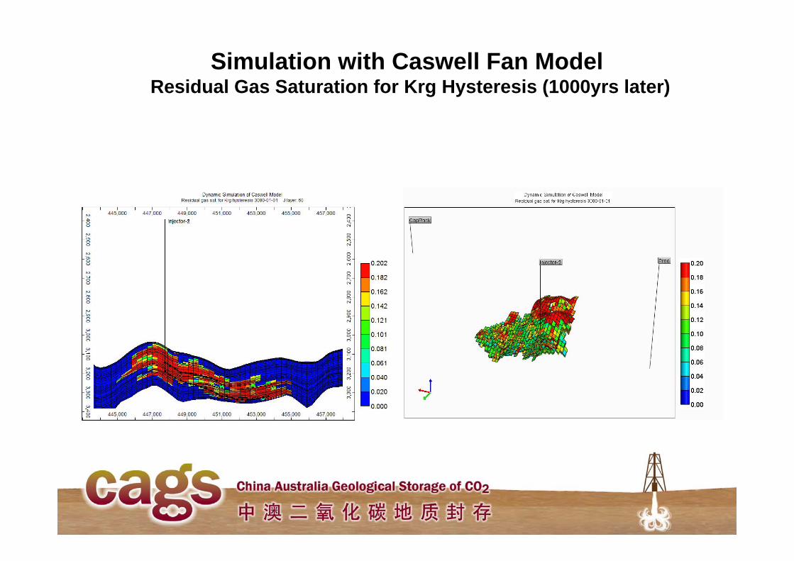
Simulation with Caswell Fan ModelResidual Gas Saturation for Krg Hysteresis (1000yrs later)
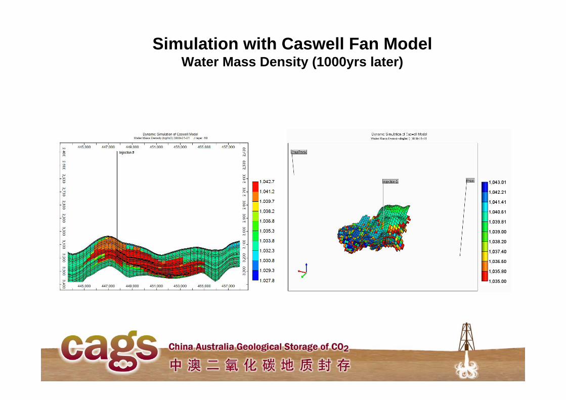
Simulation with Caswell Fan ModelWater Mass Density (1000yrs later)
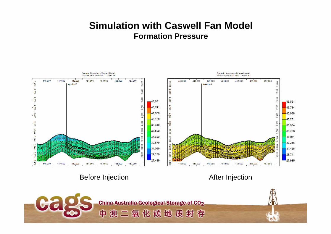
Simulation with Caswell Fan ModelFormation Pressure
Before Injection After Injection
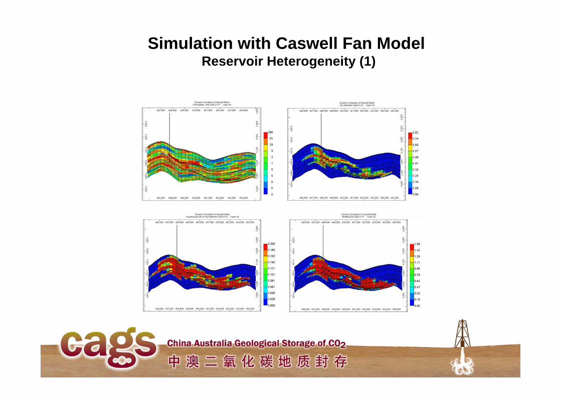
Simulation with Caswell Fan ModelReservoir Heterogeneity (1)
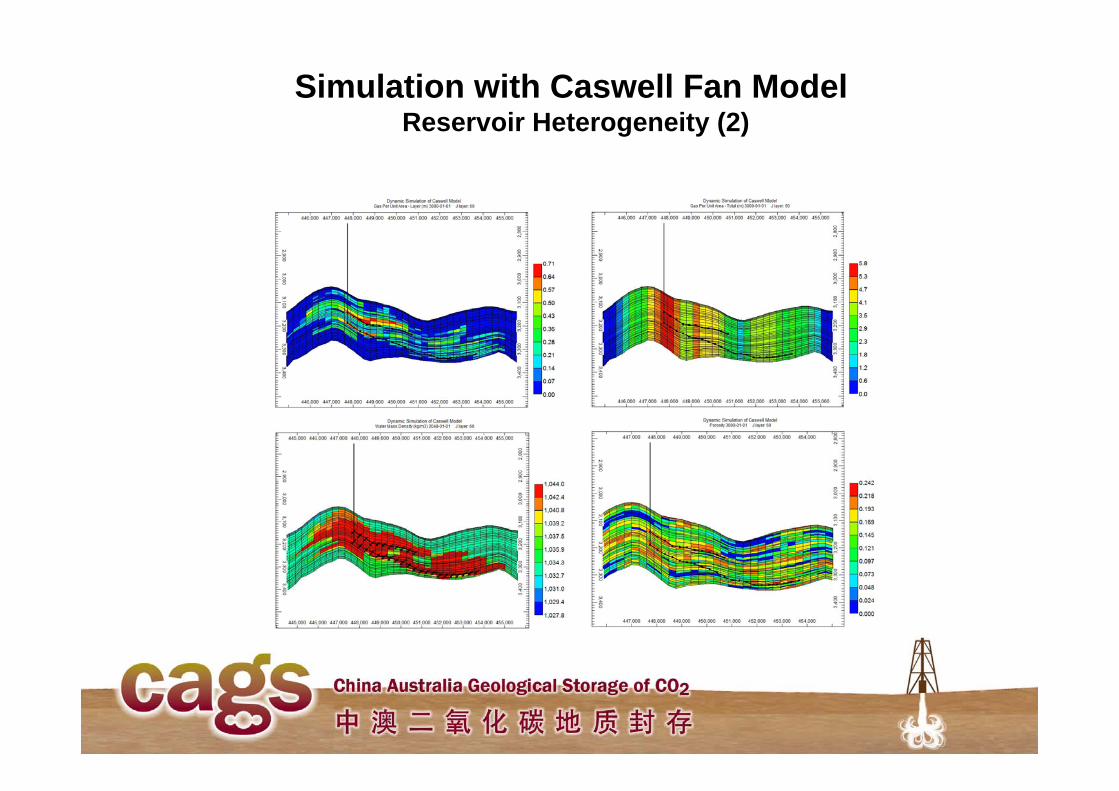
Simulation with Caswell Fan ModelReservoir Heterogeneity (2)
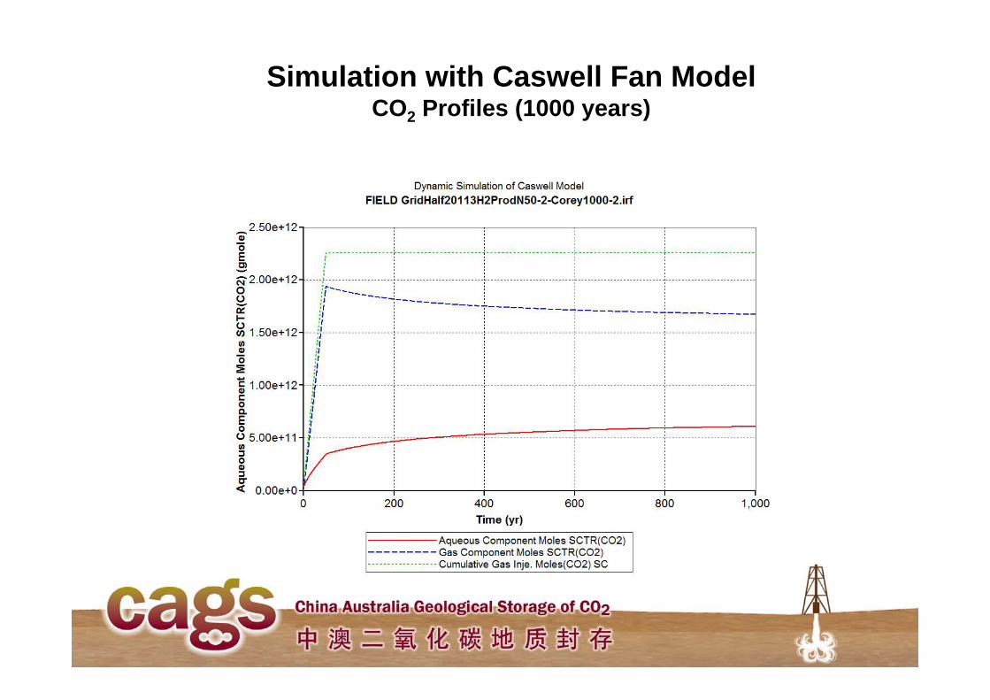
Simulation with Caswell Fan ModelCO2 Profiles (1000 years)
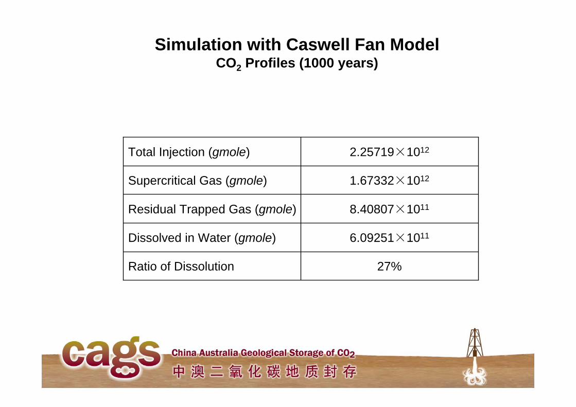
Simulation with Caswell Fan ModelCO2 Profiles (1000 years)
6.09251×10¹¹Dissolved in Water (gmole)
27%Ratio of Dissolution
8.40807×10¹¹Residual Trapped Gas (gmole)
1.67332×10¹²Supercritical Gas (gmole)
2.25719×10¹²Total Injection (gmole)
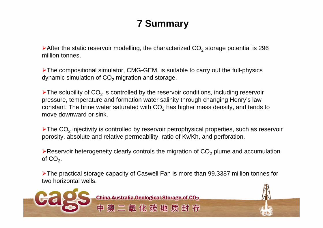
7 Summary
After the static reservoir modelling, the characterized CO2 storage potential is 296 million tonnes.
The compositional simulator, CMG-GEM, is suitable to carry out the full-physics dynamic simulation of CO2 migration and storage.
The solubility of CO2 is controlled by the reservoir conditions, including reservoir pressure, temperature and formation water salinity through changing Henry’s law constant. The brine water saturated with CO2 has higher mass density, and tends to move downward or sink.
The CO2 injectivity is controlled by reservoir petrophysical properties, such as reservoir porosity, absolute and relative permeability, ratio of Kv/Kh, and perforation.
Reservoir heterogeneity clearly controls the migration of CO2 plume and accumulation of CO2.
The practical storage capacity of Caswell Fan is more than 99.3387 million tonnes for two horizontal wells.