Embed Size (px)
Citation preview

This article was downloaded by: [University of New Mexico]On: 14 October 2014, At: 04:52Publisher: Taylor & FrancisInforma Ltd Registered in England and Wales Registered Number: 1072954 Registered office: Mortimer House,37-41 Mortimer Street, London W1T 3JH, UK
Tribology TransactionsPublication details, including instructions for authors and subscription information:http://www.tandfonline.com/loi/utrb20
The Detection and Characterization of Blisters OnCarbon-Graphite Mechanical Seal FacesPhilip J. Guichelaar a , Deborah A. Wilde a & Molly W. Williams aa Western Michigan University, Department of Mechanical and Aeronautical Engineering ,Kalamazoo, Michigan, 49008Published online: 25 Mar 2008.
To cite this article: Philip J. Guichelaar , Deborah A. Wilde & Molly W. Williams (2000) The Detection and Characterization ofBlisters On Carbon-Graphite Mechanical Seal Faces, Tribology Transactions, 43:3, 395-402, DOI: 10.1080/10402000008982355
To link to this article: http://dx.doi.org/10.1080/10402000008982355
PLEASE SCROLL DOWN FOR ARTICLE
Taylor & Francis makes every effort to ensure the accuracy of all the information (the “Content”) containedin the publications on our platform. However, Taylor & Francis, our agents, and our licensors make norepresentations or warranties whatsoever as to the accuracy, completeness, or suitability for any purpose of theContent. Any opinions and views expressed in this publication are the opinions and views of the authors, andare not the views of or endorsed by Taylor & Francis. The accuracy of the Content should not be relied upon andshould be independently verified with primary sources of information. Taylor and Francis shall not be liable forany losses, actions, claims, proceedings, demands, costs, expenses, damages, and other liabilities whatsoeveror howsoever caused arising directly or indirectly in connection with, in relation to or arising out of the use ofthe Content.
This article may be used for research, teaching, and private study purposes. Any substantial or systematicreproduction, redistribution, reselling, loan, sub-licensing, systematic supply, or distribution in anyform to anyone is expressly forbidden. Terms & Conditions of access and use can be found at http://www.tandfonline.com/page/terms-and-conditions

The Detection and Characterization of Blisters On Carbon-Graphite Mechanical Seal ~aces@
PHILIP J. GUICHELAAR, DEBORAH A. WILDE and MOLLY W. WILLIAMS Western Michigan University
Department of Mechanical and Aeronautical Engineering Kalamazoo, Michigan 49008
Blisters thnt develop on carbon-graphite tnechanical seal
fnces ore irregularities in surface topography that result in poor
sealing perfortnarlce and a high incidence of catastrophic failure.
On first inspection, a blister is a burnished area that is slightly
elevated above the surrounding seal surface. In this study, the
topography of severrrl hundred blisters was examined with inter-
ference tnicroscopy. The shape of the burnished area is typically
ellipticrrl or cylindrical. The leading edge against the direction of
romtiot~ of the mating seal ring extends abruptly upward from the
surrortnrling serrl surfrice. The trailing surface grad~rally merges
into the parent seal face. Most blisters have a tnaximum height of
0.25 pm to 0.75 prn (10 p-in to 30 p-in).
KEY WORDS
Carbon-Graphite; Face Seals
INTRODUCTION
Blistering of seal faces is a critical problem for the seal indus- try. Blisters that develop on carbodgraphite seal faces are irregu- larities in surface topography which result in poor sealing per- formance - changes in friction.torque, higher leak rates and a high incidence of catastrophic failure. The blistered seal shown in Fig. 1 has a typical appearance.
Different grades of carbodgraphite are believed to have dif- ferent susceptibilities to blistering for reasons that are not well understood. The susceptibilities to blistering are not always dupli- cated in practice. The objective of the research program underly- ing this paper was to develop a test methodology that would repro- ducibly generate blisters on carbodgraphite seal faces and to cor- relate the results of the experimental seal testing program with analytical analyses.
Presented at the 55th Annual Meeting Nashville, Tennessee
May 7-11, 2000 Final manuscript approved March 17,2000
BACKGROUND
The blistering phenomenon is observed on carbodgraphite seal faces subjected to severe service conditions. Strugala (3) found that blisters can have three different appearances, a shiny spot (Type I), a shiny spot with cracks radiating from the edges (Type II), and a pitted area with radiating cracks (Type Ill). He characterized the blisters with a severity index where a Type I has a relative severity of 1, a Type I1 has a relative severity of 2 and a Type III has a relative severity of 3. Strugala showed that the onset of blistering occurred more readily at higher values of seal face pressure and rotational velocity and with higher viscosity process fluids. His study also showed that stop-start cycling was an essential factor in the development of carbodgraphite blisters. Blisters did not form under conditions of constant speed opera- tion. Strugala's experiments also established that blisters change as the number of on-off cycles accumulates, acquiring radial cracks and then spalling out to leave a pit, a Stage I11 blister.
Miyazawa, et al. (2) found cracks underneath blisters and relat- ed their formation to erratic torque variations. He concluded that blister generation is related to the mechanical properties of the carbodgraphite seal material. Uchibori et al. (5) showed that blis- tering could be initiated by micro-fracturing at asperity summits that resulted from frictional shearing forces. The extent of blis- tering was related to high values of starting torque, in turn related to the shear strength of the carbon-graphite. They also showed that different grades of carbon have different tendencies for blis- ter formation.
EXPERIMENTAL PROCEDURE
The experimental apparatus used in this investigation was designed and modified with two primary objectives:
to closely simulate the operating conditions of mechanical seals, and,
to provide the data necessary for understanding the phenom- enon of blister formation on carbon-graphite seal faces.
Dow
nloa
ded
by [
Uni
vers
ity o
f N
ew M
exic
o] a
t 04:
52 1
4 O
ctob
er 2
014

Dow
nloa
ded
by [
Uni
vers
ity o
f N
ew M
exic
o] a
t 04:
52 1
4 O
ctob
er 2
014

The Detection and Characterization of Blisters on Carbon-Graphite Mechanical Seal Faces 397
Protocol for a Typical Experimental Run
The data discussed in this paper were obtained from an extended series of experimental runs that were designed to deter- mine the effect of the number of startup cycles on the tendency for blister formation among five different carbon-graphite grades. The important elements of the experimental procedure were:
Prior to test Document seal face geometry. (Seals were consistently flat within two light bands and had a surface finish less than 63nm Ra. Therefore this step was not regularly included).
Measure seal face for waviness - traverse seal face at OD, mid-face, ID Record surface roughness by interference microscopy.
Glue thermocouple to carbon-graphite seal with epoxy cement, along inner diameter and just below face. Install seal set in test chamber, connect face thermocouple leads.
Clean seal faces with acetone, then apply light coating of oil to each face.
Bolt end plate to chamber, applying 155 N (35 Ibf) of spring force.
Fill accumulator with new oil, degas with mechanical vacuum pump for 20 minutes.
Evacuate air from chamber and connected tubing. Pressurize accumulator to drive oil into chamber and achieve desired system pressure, nominally 540 kPa (78 psig).
Set cycle controller: 20 minutes rotation at 3600 rpm, 40 min- utes cooling.
Set number of cycles: 5, 10, 20, 50, or 100 cycles. Set sampling interval for data acquisition system: nine sec- onds for most tests.
Start test.
At end of test Depressurize system, drain and discard oil. Remove seals, soak in acetone for 1 to 2 hours to leach oil out of porosity. Survey entire surface of carbon seal face for blisters using interference microscope, save data file for each blister, print blister data and representation, place in notebook.
Detection and Characterization of Blisters
Inre$erence Microscopy A WYKO RST-plus vertical interference microscope was used
to detect and measure blisters. This instrument determines surface topography using optical interference principles. Light traveling down the microscope column is split into a main beam and a ref- erence beam that is reflected off an optical flat. When these beams recombine following reflection of the main beam off the sample, an interference pattern is created based upon whether the distance to the sample is the same as the distance to the reference flat. In the mode that was used in this research, the microscope body moves down through focus while white light fringes develop and move across the field. Each pixel in the field scanned by a CCD
camera undergoes a variation in intensity, for which the maximum occurs when the elevation of that point on the sample is at a dis- tance equal to that of the reference. Based upon this information, a vertical coordinate (Z direction height) is determined for each pixel (representing X and Y coordinates of the area being viewed). This data set can then be analyzed or displayed in a variety of ways. The instrument has a vertical resolution of 3 nm (0.12 pin). The size of the field of view of the instrument ranges from a max- imum of 8.2 by 6.3 mm (0.33 by 0.25 inches) with a lateral reso- lution of 23 pm (0.90 mils) to a minimum of 150 by 100 pm (0.006 by 0.004 inches) with a lateral resolution of 0.43 pm (17 pin). Maximum vertical travel capability is 160 pm.
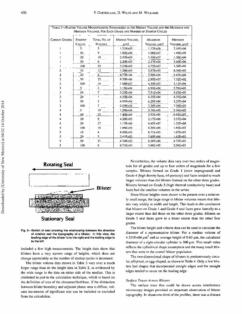
The test methodology that was developed for detection and measurement of blisters is sensitive and reproducible. As shown in Fig. 3, carbon-graphite seal faces fit closely within the rotating stage that was specially built for this project. The rotation pin hole is used to locate the zero position of the seal face in the angular direction. As the stage is rotated, the image in the CCD camera monitor shows an alternating pattern of light and dark fringes that are roughly parallel for a flat seal face. However, when the surface is not flat, such as when a blister is present, the fringe pattern abruptly changes to a series of whorls, similar to a fingerprint. When that type of fringe pattern is observed, stage rotation is stopped, the angular position is recorded, and the surface topogra- phy is measured. Proprietary software converts the X, Y, Z matrix of measurement data into color-enhanced 2-D and 3-D images or uses the data to calculate surface finish statistics. A typical repre- sentation is shown in Fig. 4. The data can also be used to construct surface traces across the blister in the x and y directions.
Interference microscopy thus provided the following informa- tion for each seal face examined:
Detection of individual blisters, Azimuthal location of each blister, Color-enhanced image of blister shape, Surface traces across blister, Width, length and height of each blister, Volume extending above surrounding surface.
While blisters that are larger than about 2.5 mm (0.100 in.) could usually be viewed on seal faces with the naked eye because their surfaces are burnished to a higher reflectivity than the sur- rounding surface, blisters as small as 0.25 by 0.18 mm (0.010 by 0.007 inch) were detected and also measured with interference microscopy.
Raman Spectroscopy A Renishaw Microfocus Raman Spectroscope was used to
characterize the structure of a few blisters. In Raman spec- troscopy, incident light in the visible or near infrared range is scat- tered from a specimen. While most of the scattered light has the same frequency as the incident light, a small fraction is shifted in frequency by the chemical bond energy of the specimen. These frequency shifts permit identification of bond energies character- istic of different phases.
The method is particularly sensitive to structural changes in carbon-graphite materials and can quickly distinguish charcoal,
Dow
nloa
ded
by [
Uni
vers
ity o
f N
ew M
exic
o] a
t 04:
52 1
4 O
ctob
er 2
014
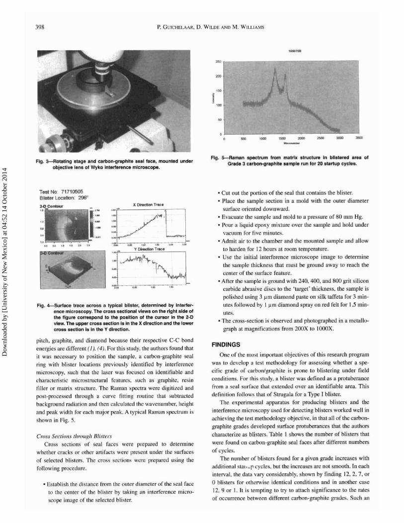
fig. 3-Rotatlng atage and cnrhtgraphhe eeel m, mourned under oblectlve lens 01 Wyko tnterterence microscope.
Test No: J l f f 0505 Blldm L e n : 2W
Fig. 4-SuW Imcs s e m 8 ZVpfaI bllrilw, ddermlned by InMer- once microscopy. The cross sactlonal vlewe m tha rlgM aide of the figure correspond to the pusltion of the cumor In the 2-0 vlew. The upper cmss secllun is in the X dltectlon end the tower cross sectton lr in the Y dlrectlon.
pitch, ppbite . and diamond becnuse their respective C-C hond cnergies nre different (1). (4) . For this study. the authors found that it necessary to position the sample, a carhnn-graphite seal: ring with Mister Imations previously identified hy interference microscopy. such that the laser was focuwd on identifiable and characcterigiic micmstructural lentures, such as graphite. resin tiller or matrix structure. The Rsmm s p c m wcrc digitized and past-pmcessed ~hmuph a curve fitling muline that subtracted hnckgmund radiation and then calculated the wavenumber. height and peak width For each major penk. A typical Raman sptclmm is shown in Fig. 5.
Cmss S ~ c t i f ~ n . ~ t f t r n ~ ~ ~ h Rli.~ter.~ Cmsa sec~ions of seal faces were prepared to determine
whether crocks or other anihc~q were present under the surfaces
of selected hlistem. The cross sections were pmpared using the following procedure.
Eslnhlish the distance fmm fie outer diameter of the seal face to the center of' the blister by taking an interference micrn- scope image of the selected blister.
Rg. -men apeetrum fmm rnw s m c i m In b l l M a m d Grade 3 mrbon-gmphlte sampk nm lor 20 startup cycles.
Cut out the podon of the seal that contains the blister. * Place the sample section in a mold with the outer diameter
surface oriented downward. Evacuate the mrnple and mold to a pressure of %a mm Hg. Pour a liquid epoxy mixture over thc sample and hold under vacuum thr five minutes.
Admil air to the chamber and the mounted sample and atlow to harden for 12 hours at room kernperamre. Use the initial interference microscope image to determine the sample thickness that must be p u n d away to reach rhc center of the surface feature. After the sample is ground with 240.41K). md ROO @I silicon carbide abrasive discs to the 'target' thickness. the sample i s polished using 3 pm diamond pxste on silk taffeta for 3 min- utes followed by I pm diamond r;pray on red felt for 1 .S min- utes. - The crnss-section i s observed and photographed in a metallo- graph nt magnifications h m 2OOX to t t000X.
FINDINGS
One nf the most important objectives of this research p r o m was to develop a test methodology for assessing whether a spe- cific grade of carbodgraphite is pmne to blistering under held conditions. For this study, a blister was defined as a protuberance from a seal surface that extend& over an identifiable area. This definition follows that of Strugala far a p p e 1 blister.
The experimentaI apparatus for producing blisters and the
interference micrmcqy used For detecting bliszm worked well in achieving the rest me tho do lo^ objective, in that all of the cnrbon- graphite grades developed surface protuberances that the authors characterize as blisters. Table 1 shows the number of hlistess that were found m carbon-graphite seal faces after different numbers of cycles.
The nvmhes of blisters round for a given p ~ d e increases with additional s t a l q cycles. but the inrreaws are not smooth. h each interval. the data vary considerably. shown hy finding 12.2.7. or 0 blisms far otherwise identical conditions and in another case 12,9 or 1. I t is rempting to try to attach significance to the rates of occurrence betwecn different carbon-pphite grades. Such an
Dow
nloa
ded
by [
Uni
vers
ity o
f N
ew M
exic
o] a
t 04:
52 1
4 O
ctob
er 2
014

The Detection and Characterization of Blisters on Carbon-Graphite Mechanical Seal Faces
TABLE I-NUMBER OF BLISTERS FOUND ON ~ N D ~ V ~ D U A L CARBON-GRAPHITE SEAL FACES AFTER THE INDICATED
NUMBER OF STARTUP CYCLES FROM A ROOM TEMPERATURE CONDITION - -- - - - - - - - - - . .
GRADE CYCLES CYCLES CYCLES CYCLES CYCLES GRADE DESCRIFTION '
0.3,2 5,2,2 7,12,0 6,8 17,34,3 Base, resin impregnated -
O,o, 1 5,7,0 2,2,0 8 , 5 , 9 7,7 Base, antimony impregnated I 3 1 2,4,1 O,O,l 1 0,0,2 7,O 1 Base, partially resin 4 1 1.18.0 1 12.9.1 1 2.3.4 17.3.12 1 12.4 High densirv base, nil oorositv
analysis would indicate that Grade 5 has less tendency to form blisters and Grade 4 has a high tendency. However, the authors do not believe that there is any statistical significance to the occur- rence of fewer or more blisters on any of the grades and for any number of cycles. Considered in their entirety, the data show that the occurrence of blisters is not predictable.
A permanent record of the shape and dimensions of each blis- ter was made in the course of detecting the blisters by interference microscopy. This record includes the following features:
Sample Number Code for each test run, listed on sample tags and data files
Cycles Number of startup cycles Blisters Number of blisters found on a particular
sample, characterized by: Location Counterclockwise angle from anti-rotation
pin hole, degrees
Width Estimated from 2-D representation, radial direction on seal, pm.
Length Estimated from 2-D representation, angular direction on seal, pm.
Volume Calculation, distance above surrounding flat surface, cubic pm
Thickness Value derived from volume calculation 2-D Shape Described from general form of 2-D
representation Dominant Slope The edge of the blister cross-section that
showed a more abrupt slope in the angular direction, as the leading or trailing edge.
The blister height data for each carbon grade are summarized in Table 2. The averages show that the measured height of most blisters is between 0.2 pm and 1.3 pm. The standard deviations are large in comparison to the averages because each data set
Dow
nloa
ded
by [
Uni
vers
ity o
f N
ew M
exic
o] a
t 04:
52 1
4 O
ctob
er 2
014
Rotating Seal t
r --------.. i -*- -.' . I
TAI3l.E 3-BI.ISTER VOLUME MEASUREMENTS SUMMAR~ZED AS THE MEDIAN VOLUME AND THE MAXIMUM AND
MINIMUM VOI.UMES, FOR EACH GRADE AND NUMBER OF STARTUP CYCLES . -
MINIMUM
I 2.188+04 - - ~ - -
I I I
. .. .
2 - ~ - ~ppp .
2 .. . -20 2 . - 5 0 9 . ! 0 ! - _ - - - ~
2 4.30E+07 2.l2E+04
3 -- 6.908+04 ! 2.598+03 3 ~ 3.238+04 7.5 1 E+04 5.638+03 3 20 3
~~ -~ 50 2 - -- - - 4.9 1 E+04
3 100 4 .~ .- 5 4 4 4 50 - - - ..
27 - . - - . . - - - -. . 4.458+07 4 100 ~.
5 . ..~ -!t .. . . .~ 4 5 - - - 20. 3 2.4 1 E+03 2.608+04 ! 1.438+03
I - I Blister
_ .- .
5 5
Stationary Seal
Flg. 6--Sketch of seal showing the relatlonshlp between the direction of rotatlon and the topography of a blister. In this view, the leading edge of the bllster Is to the right and the trailing edge is to the left.
.- -. - 50 .
100
includcd a few high measurements. The height data show that blisters hovc a very narrow range of heights, which does not change appreciably as the number of startup cycles is increased.
'The blister volume data shown in Table 3 vary over a much larger range than do the height data in Table 2, as evidenced by thc wide range in the data on either side of the median. This is attributed in part to the calculation technique, which is based on thc dcl'inition or area of the circulnscribed base. If the distinction betwecn blister boundary and adjacent planar area is diffuse, vol- ume increments of significant size can be included or excluded from thc calculation.
Nevertheless, the volume data vary over two orders of magni- tude for all grades and up to four orders of magnitude for a few samples. Blisters formed on Grade 1 (resin impregnated) and Grade 4 (high density base, nil porosity) seal faces tended to much larger volumes than did blisters formed on the other three grades. Blisters formed on Grade 5 (high thermal conductivity base) seal faces had the smallest volumes in the series.
Since blister heights were shown to be present over a relative- ly small range, the large range in blister volumes means that blis- ters vary widely in width and length. This leads to the conclusion that blisters on Grade I and Grade 4 seal faces grew laterally to a larger extent than did those on the other three grades. Blisters on Grade 5 seal faces grew to a lesser extent than the other four grades.
The blister height and volume data can be used to calculate the diameter of a representative blister. For a median volume of 4.351E+04 Clm3 and an average height of 0.63 pm, the calculated diameter of a right-circular cylinder is 300 pm. This small value reflects the cylindrical shape assumption and the many small blis- ters that were in the overall blister population.
The two-dimensional shape of blisters is predominately circu- lar, elliptical, or egg-shaped, as shown in Table 4. Only a few blis- ters had shapes that incorporated straight edges and the straight edges tended to occur on the leading edge.
-. %28E&L6-4. - _ 4 . 1 2 2 - - .. . -2 1 -
Surface Traces Across Blisters
The surface trace that could be drawn across interference microscopy images provided an important observation of blister topography. In about one-third of the profiles, there was a distinct
6 6.71E+03 1 3.48E+05 1 2.068+03 - 4.74EyO3
Dow
nloa
ded
by [
Uni
vers
ity o
f N
ew M
exic
o] a
t 04:
52 1
4 O
ctob
er 2
014

The Detccrion and Chanc~cri~ation of Blirters on Cnrhon-Gmphite Mechanical Scnl Faces 30 1
I.- :---.--7- - . - z v -,
Fig. 7-Swbce w m m blister ahowlng b e p M ores sdjncant to the smp sIW me.
difference bctwcen the nlape af the vcnical edges n! either side o l the hlisrcr. one being more steep and the orher he in^ more gentle.
W m e observations nre summarized in Table 5. A skerch showing thc definition for leading and miling edge is shown in Fig. h.
Depressed areas mwmhling cmcks were often observed to k presen! immediately Rdjacent lo edges with steep ~lopes. An inter- ference microscopy record of one st~ch ohsewation i s shown in
Fig. 7. Fmm the unalysis of blister profiles m d t l ~c unalysis of the 2-
D shape. the authors find that most uf h c blisters tha~ were fr~rtned and detected in 1hi5 portion of (he research study had acylindricnl shape. They also hnd a sloped edge amund their boundary lhat tended to he steepcr on the leading edge.
Blisters often nppear. on simple visual examination of an entire seal face, to occur in a regular pattern iiround the face of a sca3. This i s an important obw;esvntion. since if blisters occur in n regu- tar pattern and do so on a repeatable bmis. then their genesis is more likely to he related to a harmonic perturbation of the sealing
system or n geometrical basis. such as thermr~lwric instability or a lack of flarness after lapping. Instead. our ohservatiuna indicak- ed t h a ~ thc mcurrence of hlisters was random, such as from lw:bI changes in mnterinl properlies or the presence of structural flaws.
Rnr~nn Sp~crmscop.~ The major pcaks for disordered carbofis are the 1357 and 15XO
crn'hands. which nrc commonly designated as the D and G hunds mpectively ( I ) . The amount of disorder in differcnl carhon slruc- lures correlates with I ) the wnvenumhcr of the G band. 2 ) thc width of the C band. and 3) the DIG intznsity ratio. which i s the ntio of the peak heights of the FWO bands.
Flg. 8-C-Ion through bllsttrr ?tmi formed on tiw s u m ol a Grade 2 carbon sttar running egalrm4 slntered slllctln mrblde 5-1 bco for 3 smconda. The rotation direclimn of tha countw- face Is lo the rlghl. Sample lt3f1495 @ 270'.
Signilican~ly. thc Raman dau LG hand wavemember, G hand widrh. ;md DIG intensity wrio) obrnincd Tram seal Facc surface^ that were adjacent tn I ~ E blistem were vinually ~ h c samc as rht: data oh~ained from the surface r)fblisrer?; rrnd the dau sets feSl into thc same rwo classes: graphitic and matrix. The data ohtaincd from the hacksidcs ol'hc seals werc not ns conclusive. mostly due to higher hackgrounds attributed to the presence of oil that was
not fully lenched out during wmplc prcpmtion. The Raman spxtrnscopy and the assrlcintPrt l igh~ rnicn~sctlpy
thus show that blistcn have graphite and matrix micmsrmc~ural features that are visually and svuctunlly identical tu !he adjawnt seal material. The nuthm conclude that blisters derive from llie carbun-graphitc sed face.
C ~ S . F Sections rlrmuglr Btisr~rs Because i t i s premised on plncing the perpendiculnr plane o f
polish precisely through [he center nF the hlislcr, commonly with- in a range of 0.25 mm. this technique does not coi~sistcntly find a
m c k that may he under a given blister. The~fore. the technique d m not defimitivcty pmvc thnr all btiste~fi huve underlying cmcks. However. cracks of this typical appearance were found in the V ~ I majoriQ of blister cmss scaions that were examined. a5 can be seen in Fig. 8.
CONCLUSIONS
Interference micmscapy i s 3 sensitive and reproducible rech- nique for the detection and chamczerizerion of hlistcs. In rhis study. blisters as small ns 0.15 hy O . l R mm cmss sectional nwa and with elevations less rhan 0.25 prn were readily detectcd end Irrcated relative IIT a fixed Incatinn on each seal face. The fnllnw- ing canclt~sions are drawn from thew data.
Blisters have u vev narruw range o i heights h e ~ w e e n 0.25 pm and 0.75 pm. which does not chnngc appreciably as !he num- ber of startup cycles is incwnsed. The large rmgc in blister vo!umes shows that hlipterr v q w~dely an width and length.
Dow
nloa
ded
by [
Uni
vers
ity o
f N
ew M
exic
o] a
t 04:
52 1
4 O
ctob
er 2
014

The occurrence of blisters is not predictable and any mecha- nism that explains their formation must account for this ran- domness. Most of the blisters had a cylindrical shape with a sloped edge around their boundary that tended to be steeper on the lead- ing edge. Blisters can form after a small number of startup cycles or they may form after a large number of startup cycles. Blisters tend to remain the same size after they form and do not wear away.
Rnman spectroscopy showed that blisters have identical crys- lallinc and ~nicrostructural features to adjacent carbon-graphite scnl face material.
ACKNOWLEDGMENTS
This research study was sponsored by the Advanced Projects Subcommittee of the Seals Technical Committee of STLE and was funded by 14 industrial members.
Dr. Alan Krauss and Dr. Dieter Gruen of Argonne National Laboratory graciously provided access to a Renishaw Microfocus Raman Spectroscope.
The authors are pleased to acknowledge the contributions of the following students who designed and built experimental equipment, ran tests, and searched for blisters: David Frye, Del Thomas, Matt Haywood, Dave Woodard, Jeff Ford, Heather Atwood. Steve Pride and Dave Hurlbert.
REFERENCES ( I ) Knight, D. S. and White, W. B., "Characterization of Diamond Films by Raman
Spectroscopy," Joitc Marec Res., 4-2, pp 385-393, (1989). (2) Miyazawa, M.. el al.. "Observations on Generation of the Carbon Blister
Phenomena on Mechanical Seals," Lubc Eng.. 44. pp 520-526, (1988). (3) Strugala, E. W., 'The Nature and Causes of Seal Carbon Blistering," Lubc Eng.,
28. pp 333-339. (1972). (4) Tanabe. T., Niwase, K.. Tsukuda, N. and Kuramoto, E., "On the Characterization
of Graphite." Jouc Nucl. Marer., 191-194, pp 330-334, (1992). (5) Uchibori, Z., el al., "Fundamental Study of the Carbon Blister Generation at the
Starting Period on Mechanical Seals," Lubc Eng., 47. pp 847-858, (1991). (6) Williams, M. W. and Pilletteri, V. J., "A Fully lnslmmented System for the
Measurement of End Face Mechanical Seal Performance Under Simulated Service Conditions." Lntbc Eng., 52, pp 809-815, (1997).
Dow
nloa
ded
by [
Uni
vers
ity o
f N
ew M
exic
o] a
t 04:
52 1
4 O
ctob
er 2
014