Embed Size (px)
Citation preview
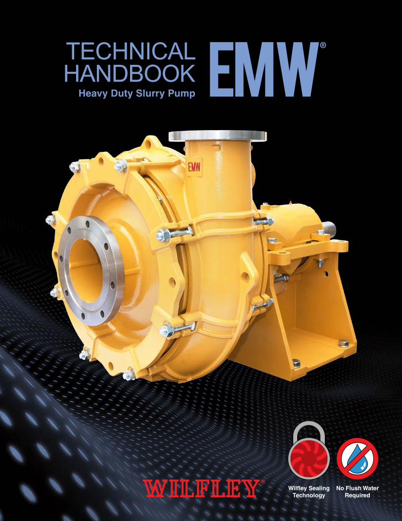
TECHNICALHANDBOOK
Heavy Duty Slurry Pump EMW ®
Wilfley SealingTechnology
No Flush WaterRequired
1
WILFLEY SEALING TECHNOLOGY
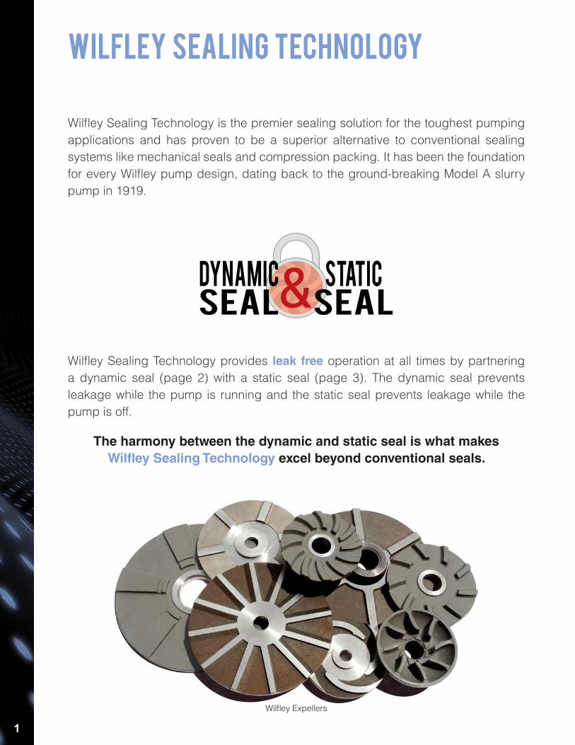
Wilfley Sealing Technology is the premier sealing solution for the toughest pumping applications and has proven to be a superior alternative to conventional sealing systems like mechanical seals and compression packing. It has been the foundation for every Wilfley pump design, dating back to the ground-breaking Model A slurry pump in 1919.
Wilfley Sealing Technology provides leak free operation at all times by partnering a dynamic seal (page 2) with a static seal (page 3). The dynamic seal prevents leakage while the pump is running and the static seal prevents leakage while the pump is off.
The harmony between the dynamic and static seal is what makes Wilfley Sealing Technology excel beyond conventional seals.
Wilfley Expellers
2
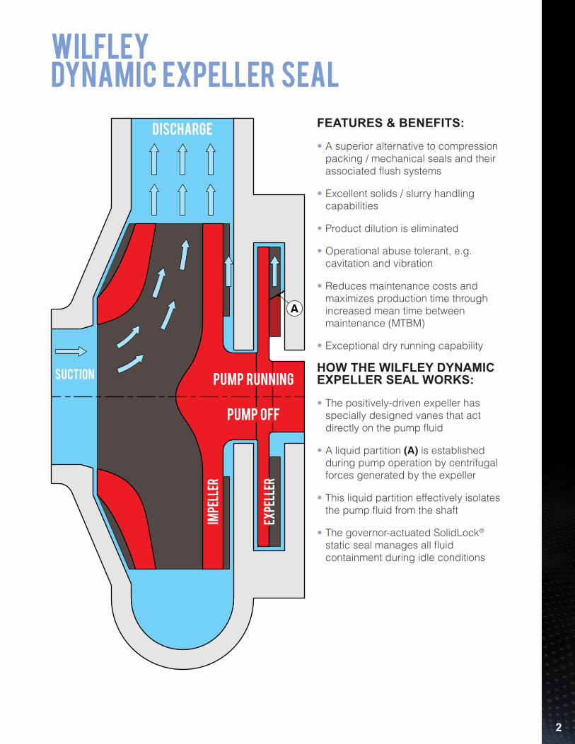
WILFLEYdynamic EXPELLER seal
FEATURES & BENEFITS:
• A superior alternative to compression packing / mechanical seals and their associated flush systems
• Excellent solids / slurry handling capabilities
• Product dilution is eliminated
• Operational abuse tolerant, e.g. cavitation and vibration
• Reduces maintenance costs and maximizes production time through increased mean time between maintenance (MTBM)
• Exceptional dry running capability
HOW THE WILFLEY DYNAMIC EXPELLER SEAL WORKS:
• The positively-driven expeller has specially designed vanes that act directly on the pump fluid
• A liquid partition (A) is established during pump operation by centrifugal forces generated by the expeller
• This liquid partition effectively isolates the pump fluid from the shaft
• The governor-actuated SolidLock® static seal manages all fluid containment during idle conditions
A
Pump Running
Pump off
impe
ller
expe
ller
discharge
suction
3
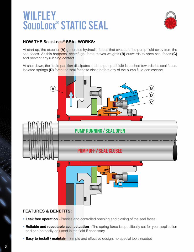
HOW THE SOLIDLOCK® SEAL WORKS:
At start up, the expeller (A) generates hydraulic forces that evacuate the pump fluid away from the seal faces. As this happens, centrifugal force moves weights (B) outwards to open seal faces (C) and prevent any rubbing contact.
At shut down, the liquid partition dissipates and the pumped fluid is pushed towards the seal faces. Isolated springs (D) force the seal faces to close before any of the pump fluid can escape.
Pump Running / Seal Open
Pump Off / Seal Closed
FEATURES & BENEFITS:
• Leak free operation - Precise and controlled opening and closing of the seal faces
• Reliable and repeatable seal actuation - The spring force is specifically set for your application and can be easily adjusted in the field if necessary
• Easy to install / maintain - Simple and effective design, no special tools needed
A B
D
C
WILFLEYSolidlock
® STATIC seal

4
emw® sLURRY PUMPSealING options
The EMW® pump has been designed to accommodate a wide variety of sealing options to specifically suit your
application.
SolidLock® Lite(Diaphragm Seal with Expeller)
Expeller with Compression Packing(Weep Configuration Shown)
Single / Double Mechanical SealsCompression Packing(Flush Configuration Shown)
SolidLock® with Purge Port(Start Up and / or Shut Down Washout Capability)
Over-sized, self aligning tapered roller bearingsfor trouble free operation
11
Labyrinth seals to protect internal componentsduring wash-down cycles
10
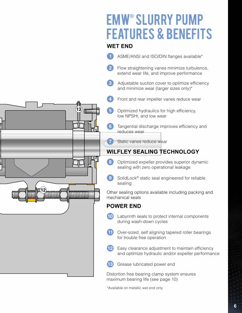
Static vanes reduce wear7
Tangential discharge improves efficiency andreduces wear
6
Optimized hydraulics for high efficiency,low NPSHr, and low wear
5
Optimized expeller provides superior dynamicsealing with zero operational leakage
8
SolidLock® static seal engineered for reliablesealing
9
Grease lubricated power end13
Easy clearance adjustment to maintain efficiencyand optimize hydraulic and/or expeller performance
12
Other sealing options available including packing andmechanical seals
POWER END
WILFLEY SEALING TECHNOLOGY
WET END
Flow straightening vanes minimize turbulence,extend wear life, and improve performance
2
ASME/ANSI and ISO/DIN flanges available*1
3 Adjustable suction cover to optimize efficiencyand minimize wear (larger sizes only)*
4 Front and rear impeller vanes reduce wear
EMW® Slurry Pumpfeatures & benefits
Distortion free bearing clamp system ensuresmaximum bearing life (see page 10)
*Available on metallic wet end only
4
1
132
3
5
6
7
8
1110
12
9
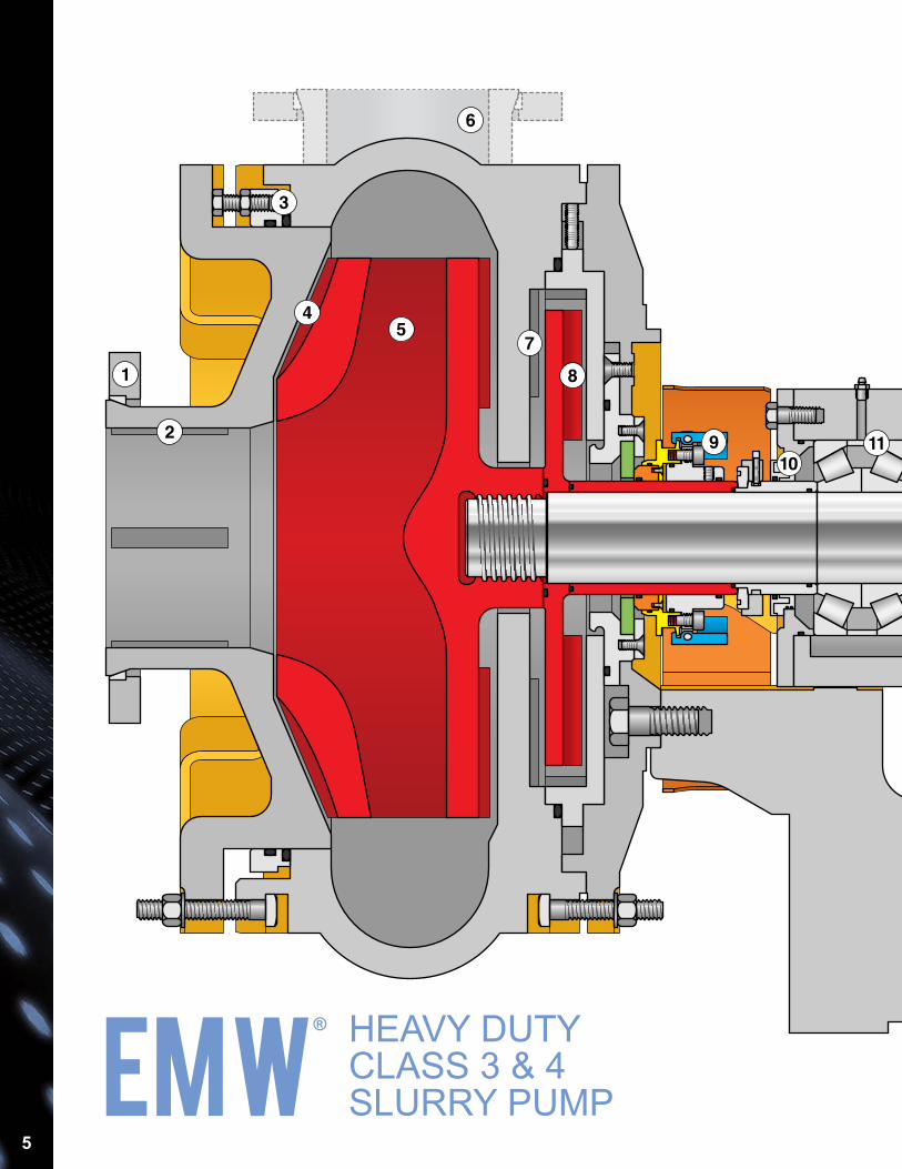
HEAVY DUTYCLASS 3 & 4SLURRY PUMPEMW
®
5
Over-sized, self aligning tapered roller bearingsfor trouble free operation
11
Labyrinth seals to protect internal componentsduring wash-down cycles
10
Static vanes reduce wear7
Tangential discharge improves efficiency andreduces wear
6
Optimized hydraulics for high efficiency,low NPSHr, and low wear
5
Optimized expeller provides superior dynamicsealing with zero operational leakage
8
SolidLock® static seal engineered for reliablesealing
9
Grease lubricated power end13
Easy clearance adjustment to maintain efficiencyand optimize hydraulic and/or expeller performance
12
Other sealing options available including packing andmechanical seals
POWER END
WILFLEY SEALING TECHNOLOGY
WET END
Flow straightening vanes minimize turbulence,extend wear life, and improve performance
2
ASME/ANSI and ISO/DIN flanges available*1
3 Adjustable suction cover to optimize efficiencyand minimize wear (larger sizes only)*
4 Front and rear impeller vanes reduce wear
EMW® Slurry Pumpfeatures & benefits
Distortion free bearing clamp system ensuresmaximum bearing life (see page 10)
*Available on metallic wet end only
4
1
132
3
5
6
7
8
1110
12
9
HEAVY DUTYCLASS 3 & 4SLURRY PUMPEMW
®
6
7
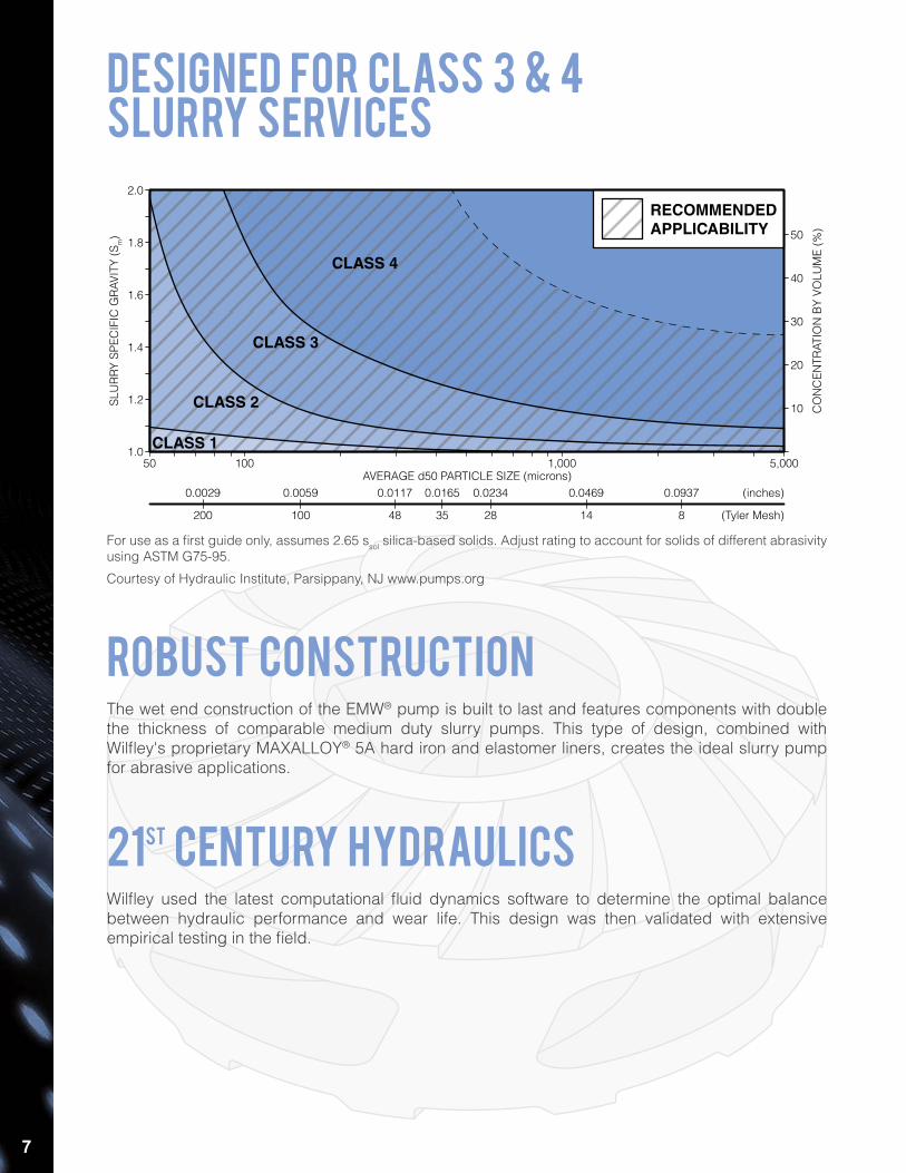
designed for class 3 & 4slurry services
ROBUST constructionThe wet end construction of the EMW® pump is built to last and features components with double the thickness of comparable medium duty slurry pumps. This type of design, combined with Wilfley's proprietary MAXALLOY® 5A hard iron and elastomer liners, creates the ideal slurry pump for abrasive applications.
(Tyler Mesh)
(inches)0.0029 0.0059 0.0117 0.0165 0.0234 0.0469 0.0937
200 100 48 35 28 14 8
SLU
RR
Y SP
ECIF
IC G
RAV
ITY
(Sm)
1.6
1.8
2.0
1.0
1.4
1.2
CO
NC
ENTR
ATIO
N B
Y VO
LUM
E (%
)
30
40
50
20
10
AVERAGE d50 PARTICLE SIZE (microns)1,000100 5,00050
CLASS 1
CLASS 2
CLASS 3
CLASS 4
RECOMMENDEDAPPLICABILITY
For use as a first guide only, assumes 2.65 ssol silica-based solids. Adjust rating to account for solids of different abrasivity using ASTM G75-95.
Courtesy of Hydraulic Institute, Parsippany, NJ www.pumps.org
21st century hydraulicsWilfley used the latest computational fluid dynamics software to determine the optimal balance between hydraulic performance and wear life. This design was then validated with extensive empirical testing in the field.
8
BREAKTHROUGHmaterialsWilfley works discreetly with key suppliers, such as Western Foundries,
to provide a variety of engineered metallurgies and proprietary processes for the longest possible pump and parts life and reliability.
This also allows Wilfley to provide very competitive lead times for both complete pumps and spare parts.
wilfley knows metallurgy
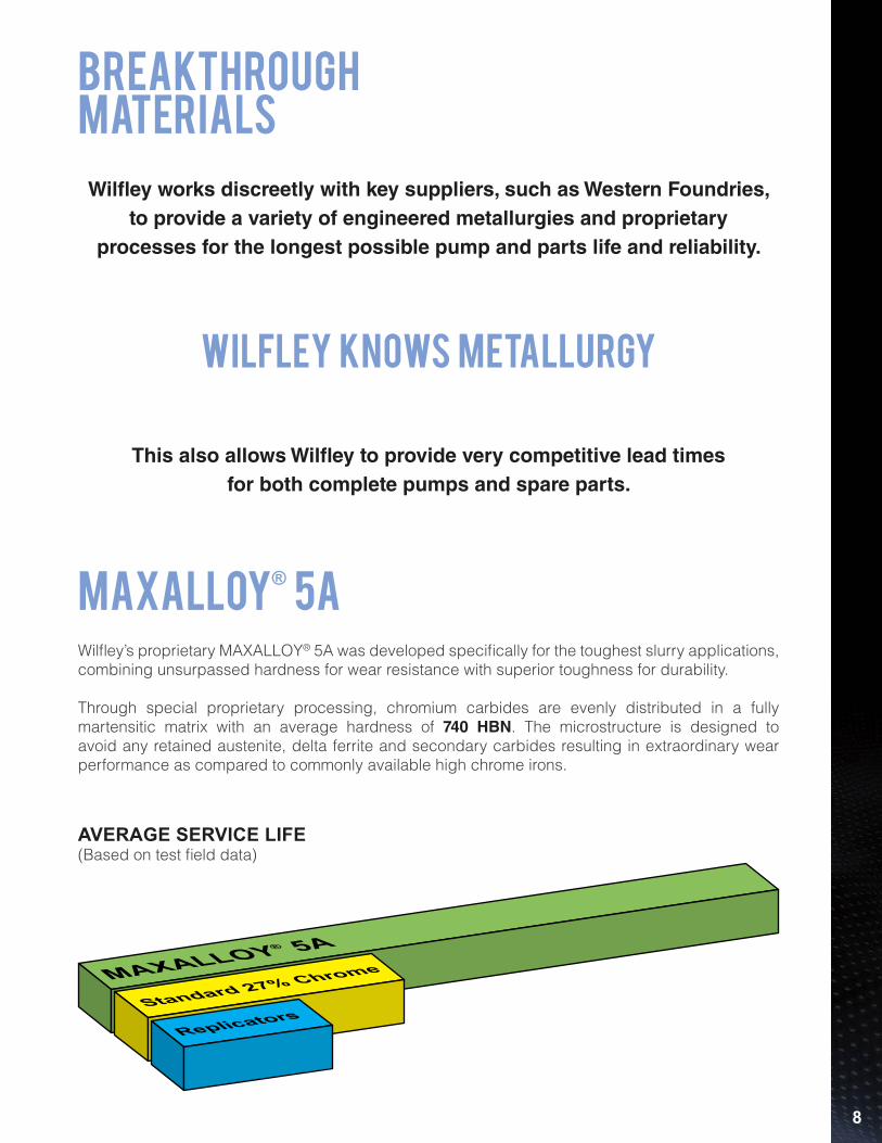
MAXALLOY® 5A
Standard 27% Chrome
Replicators
maxalloy® 5a
AVERAGE SERVICE LIFE(Based on test field data)
Wilfley’s proprietary MAXALLOY® 5A was developed specifically for the toughest slurry applications, combining unsurpassed hardness for wear resistance with superior toughness for durability.
Through special proprietary processing, chromium carbides are evenly distributed in a fully martensitic matrix with an average hardness of 740 HBN. The microstructure is designed to avoid any retained austenite, delta ferrite and secondary carbides resulting in extraordinary wear performance as compared to commonly available high chrome irons.
9
A
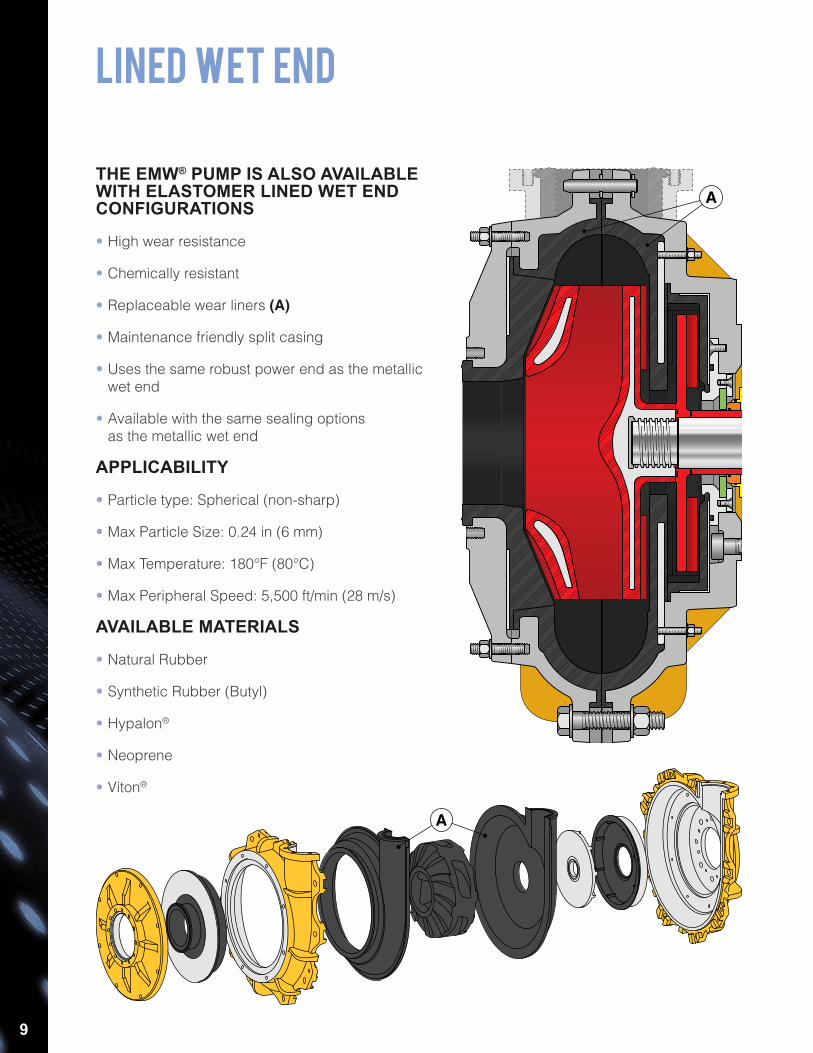
Lined Wet End
THE EMW® PUMP IS ALSO AVAILABLE WITH ELASTOMER LINED WET END CONFIGURATIONS
• High wear resistance
• Chemically resistant
• Replaceable wear liners (A)
• Maintenance friendly split casing
• Uses the same robust power end as the metallic wet end
• Available with the same sealing options as the metallic wet end
APPLICABILITY
• Particle type: Spherical (non-sharp)
• Max Particle Size: 0.24 in (6 mm)
• Max Temperature: 180°F (80°C)
• Max Peripheral Speed: 5,500 ft/min (28 m/s)
AVAILABLE MATERIALS
• Natural Rubber
• Synthetic Rubber (Butyl)
• Hypalon®
• Neoprene
• Viton®
A
10
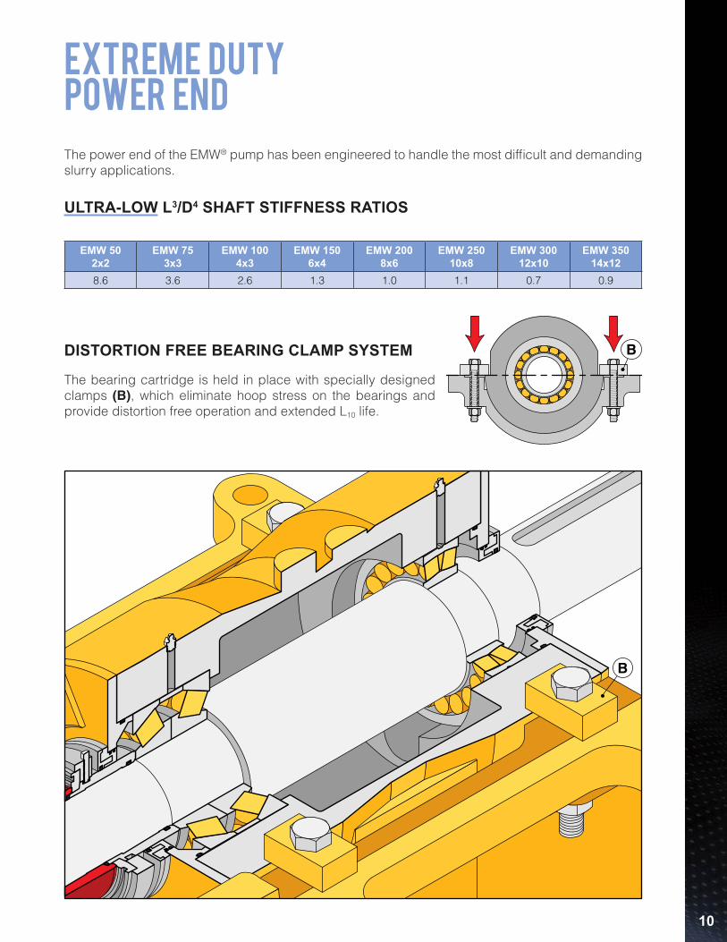
EXTREME DUTYPOWER END
DISTORTION FREE BEARING CLAMP SYSTEM
The bearing cartridge is held in place with specially designed clamps (B), which eliminate hoop stress on the bearings and provide distortion free operation and extended L10 life.
B
The power end of the EMW® pump has been engineered to handle the most difficult and demanding slurry applications.
B
ULTRA-LOW L3/D4 SHAFT STIFFNESS RATIOS
EMW 502x2
EMW 753x3
EMW 1004x3
EMW 1506x4
EMW 2008x6
EMW 25010x8
EMW 30012x10
EMW 35014x12
8.6 3.6 2.6 1.3 1.0 1.1 0.7 0.9
11
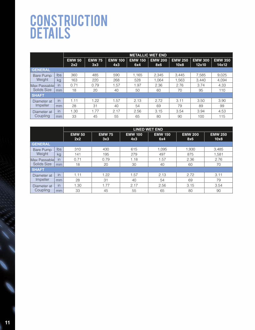
CONSTRUCTIONDETAILS
LINED WET ENDEMW 50
2x2EMW 75
3x3EMW 100
4x3EMW 150
6x4EMW 200
8x6EMW 250
10x8GENERALBare Pump
Weightlbs 310 430 615 1,095 1,930 3,485kg 141 195 279 497 875 1,581
Max PassableSolids Size
in 0.71 0.79 1.18 1.57 2.36 2.76mm 18 20 30 40 60 70
SHAFTDiameter at
Impellerin 1.11 1.22 1.57 2.13 2.72 3.11
mm 28 31 40 54 69 79
Diameter atCoupling
in 1.30 1.77 2.17 2.56 3.15 3.54mm 33 45 55 65 80 90
METALLIC WET ENDEMW 50
2x2EMW 75
3x3EMW 100
4x3EMW 150
6x4EMW 200
8x6EMW 250
10x8EMW 300
12x10EMW 350
14x12GENERALBare Pump
Weightlbs 360 485 590 1,165 2,345 3,445 7,585 9,025kg 163 220 268 528 1,064 1,563 3,440 4,094
Max PassableSolids Size
in 0.71 0.79 1.57 1.97 2.36 2.76 3.74 4.33mm 18 20 40 50 60 70 95 110
SHAFTDiameter at
Impellerin 1.11 1.22 1.57 2.13 2.72 3.11 3.50 3.90
mm 28 31 40 54 69 79 89 99
Diameter atCoupling
in 1.30 1.77 2.17 2.56 3.15 3.54 3.94 4.53mm 33 45 55 65 80 90 100 115
12
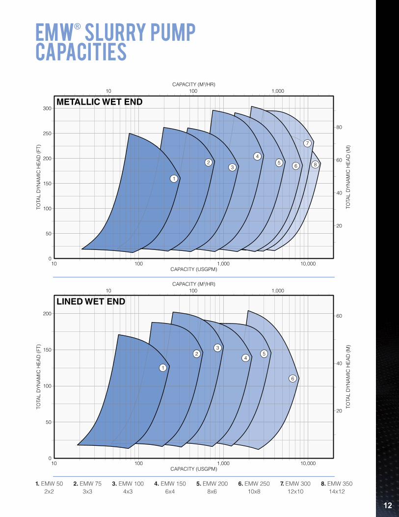
emW® slurry pumpcapacities
1. EMW 502x2
2. EMW 753x3
3. EMW 1004x3
4. EMW 1506x4
5. EMW 2008x6
7. EMW 30012x10
6. EMW 25010x8
8. EMW 35014x12
TOTA
L D
YNA
MIC
HEA
D (F
T)
TOTA
L D
YNA
MIC
HEA
D (M
)
CAPACITY (M3/HR)
METALLIC WET END
CAPACITY (USGPM)10
0
300
200
100
250
150
50
80
60
40
20
10 100 1,000
1,000100 10,000
1
23
45
6
7
8
TOTA
L D
YNA
MIC
HEA
D (F
T)
TOTA
L D
YNA
MIC
HEA
D (M
)
CAPACITY (M3/HR)
LINED WET END
CAPACITY (USGPM)
0
200
100
150
50
60
40
20
1
23
45
6
10
10 100 1,000
1,000100 10,000
13
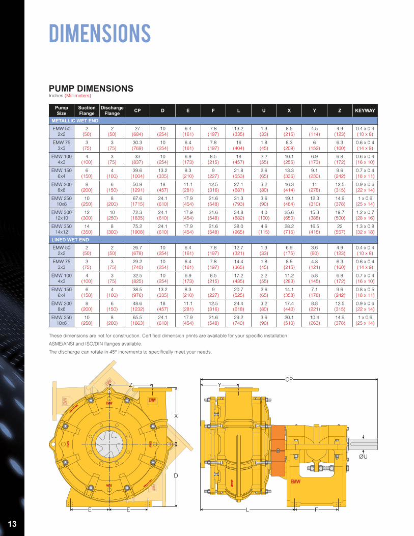
DIMENSIONS
PumpSize
SuctionFlange
DischargeFlange CP D E F L U X Y Z KEYWAY
METALLIC WET ENDEMW 50
2x22
(50)2
(50)27
(684)10
(254)6.4
(161)7.8
(197)13.2(335)
1.3(33)
8.5(215)
4.5(114)
4.9(123)
0.4 x 0.4(10 x 8)
EMW 75 3x3
3(75)
3(75)
30.3(769)
10(254)
6.4(161)
7.8(197)
16(404)
1.8(45)
8.3(209)
6(152)
6.3(160)
0.6 x 0.4(14 x 9)
EMW 100 4x3
4(100)
3(75)
33(837)
10(254)
6.9(173)
8.5(215)
18(457)
2.2(55)
10.1(255)
6.9(173)
6.8(172)
0.6 x 0.4(16 x 10)
EMW 150 6x4
6(150)
4(100)
39.6(1004)
13.2(335)
8.3(210)
9(227)
21.8(553)
2.6(65)
13.3(336)
9.1(230)
9.6(242)
0.7 x 0.4(18 x 11)
EMW 200 8x6
8(200)
6(150)
50.9(1291)
18(457)
11.1(281)
12.5(316)
27.1(687)
3.2(80)
16.3(414)
11(278)
12.5(315)
0.9 x 0.6(22 x 14)
EMW 250 10x8
10(250)
8(200)
67.6(1715)
24.1(610)
17.9(454)
21.6(548)
31.3(793)
3.6(90)
19.1(484)
12.3(310)
14.9(378)
1 x 0.6(25 x 14)
EMW 30012x10
12(300)
10(250)
72.3(1835)
24.1(610)
17.9(454)
21.6(548)
34.8(882)
4.0(100)
25.6(650)
15.3(388)
19.7(500)
1.2 x 0.7(28 x 16)
EMW 350 14x12
14(350)
8(300)
75.2(1908)
24.1(610)
17.9(454)
21.6(548)
38.0(965)
4.6(115)
28.2(715)
16.5(418)
22(557)
1.3 x 0.8(32 x 18)
LINED WET ENDEMW 50
2x22
(50)2
(50)26.7(678)
10(254)
6.4(161)
7.8(197)
12.7(321)
1.3(33)
6.9(175)
3.6(90)
4.9(123)
0.4 x 0.4(10 x 8)
EMW 75 3x3
3(75)
3(75)
29.2(740)
10(254)
6.4(161)
7.8(197)
14.4(365)
1.8(45)
8.5(215)
4.8(121)
6.3(160)
0.6 x 0.4(14 x 9)
EMW 100 4x3
4(100)
3(75)
32.5(825)
10(254)
6.9(173)
8.5(215)
17.2(435)
2.2(55)
11.2(283)
5.8(145)
6.8(172)
0.7 x 0.4(16 x 10)
EMW 150 6x4
6(150)
4(100)
38.5(976)
13.2(335)
8.3(210)
9(227)
20.7(525)
2.6(65)
14.1(358)
7.1(178)
9.6(242)
0.8 x 0.5(18 x 11)
EMW 200 8x6
8(200)
6(150)
48.6(1232)
18(457)
11.1(281)
12.5(316)
24.4(618)
3.2(80)
17.4(440)
8.8(221)
12.5(315)
0.9 x 0.6(22 x 14)
EMW 250 10x8
10(250)
8(200)
65.5(1663)
24.1(610)
17.9(454)
21.6(548)
29.2(740)
3.6(90)
20.1(510)
10.4(263)
14.9(378)
1 x 0.6(25 x 14)
PUMP DIMENSIONSInches (Millimeters)
E E
D
L F
ØU
X
Z YCP
These dimensions are not for construction. Certified dimension prints are available for your specific installation
ASME/ANSI and ISO/DIN flanges available.
The discharge can rotate in 45° increments to specifically meet your needs.
14
H
LW
H
W L
H
LW
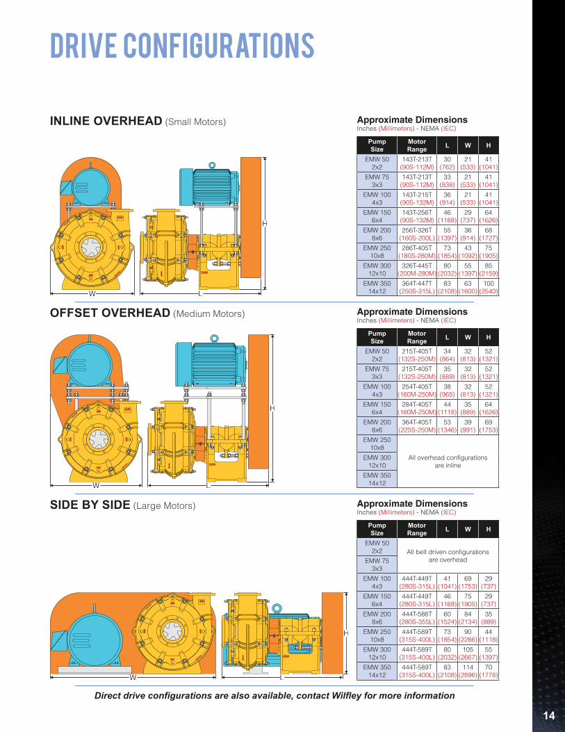
INLINE OVERHEAD (Small Motors)
OFFSET OVERHEAD (Medium Motors)
SIDE BY SIDE (Large Motors)
DRIVE CONFIGURATIONS
Approximate DimensionsInches (Millimeters) - NEMA (IEC)
Approximate DimensionsInches (Millimeters) - NEMA (IEC)
Approximate DimensionsInches (Millimeters) - NEMA (IEC)
PumpSize
MotorRange L W H
EMW 502x2
143T-213T(90S-112M)
30 (762)
21 (533)
41 (1041)
EMW 753x3
143T-213T(90S-112M)
33 (838)
21 (533)
41 (1041)
EMW 100 4x3
143T-215T(90S-132M)
36 (914)
21 (533)
41 (1041)
EMW 150 6x4
143T-256T(90S-132M)
46 (1168)
29 (737)
64 (1626)
EMW 200 8x6
256T-326T(160S-200L)
55 (1397)
36 (914)
68 (1727)
EMW 250 10x8
286T-405T(180S-280M)
73 (1854)
43 (1092)
75 (1905)
EMW 300 12x10
326T-445T(200M-280M)
80(2032)
55(1397)
85(2159)
EMW 350 14x12
364T-447T(250S-315L)
83(2108)
63(1600)
100(2540)
PumpSize
MotorRange L W H
EMW 502x2
215T-405T(132S-250M)
34 (864)
32 (813)
52 (1321)
EMW 753x3
215T-405T(132S-250M)
35 (889)
32 (813)
52 (1321)
EMW 100 4x3
254T-405T(160M-250M)
38 (965)
32 (813)
52 (1321)
EMW 150 6x4
284T-405T(160M-250M)
44 (1118)
35 (889)
64 (1626)
EMW 200 8x6
364T-405T(225S-250M)
53 (1346)
39 (991)
69 (1753)
EMW 250 10x8
All overhead configurationsare inline
EMW 300 12x10
EMW 350 14x12
PumpSize
MotorRange L W H
EMW 502x2 All belt driven configurations
are overheadEMW 753x3
EMW 100 4x3
444T-449T(280S-315L)
41 (1041)
69 (1753)
29 (737)
EMW 150 6x4
444T-449T(280S-315L)
46 (1168)
75 (1905)
29 (737)
EMW 200 8x6
444T-586T(280S-355L)
60 (1524)
84 (2134)
35 (889)
EMW 250 10x8
444T-589T(315S-400L)
73 (1854)
90 (2286)
44 (1118)
EMW 300 12x10
444T-589T(315S-400L)
80(2032)
105(2667)
55(1397)
EMW 350 14x12
444T-589T(315S-400L)
83(2108)
114(2896)
70(1778)
Direct drive configurations are also available, contact Wilfley for more information
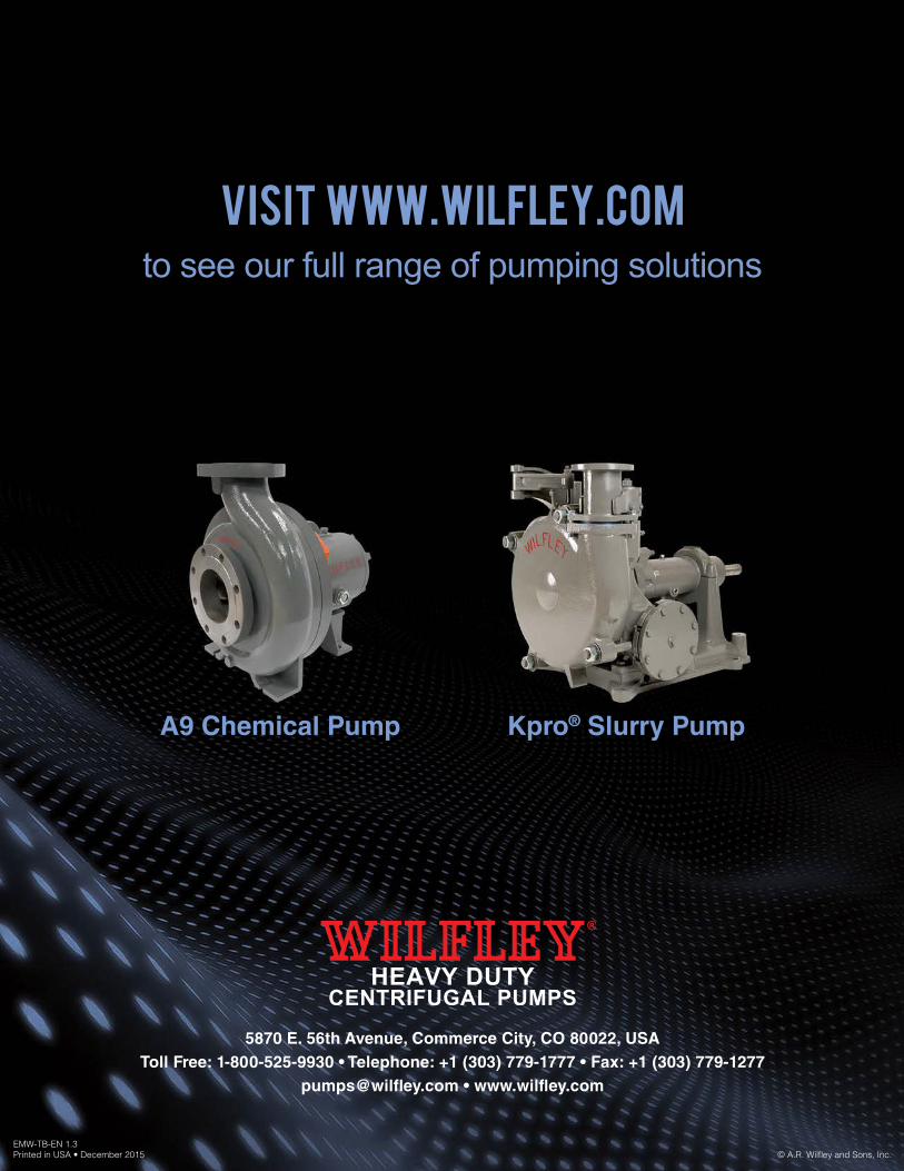
visit www.wilfley.comto see our full range of pumping solutions
A9 Chemical Pump
EMW-TB-EN 1.3Printed in USA • December 2015 © A.R. Wilfley and Sons, Inc.
5870 E. 56th Avenue, Commerce City, CO 80022, USAToll Free: 1-800-525-9930 • Telephone: +1 (303) 779-1777 • Fax: +1 (303) 779-1277
[email protected] • www.wilfley.com
HEAVY DUTYCENTRIFUGAL PUMPS
Kpro® Slurry Pump