Embed Size (px)
Citation preview
Research ArticleCan Scalable Design ofWings for FlappingWingMicro Air VehicleBe Inspired by Natural Flyers?
Yanghai Nan ,1,2,3,4 Bei Peng ,1,2,3 Yi Chen ,1,2,3,4 Zhenyu Feng,1,2 and Don McGlinchey4
1School of Mechanical and Electrical Engineering, University of Electronic Science and Technology of China, Chengdu 611731, China2Center for Robotics, University of Electronic Science and Technology of China, Chengdu 611731, China3Sichuan Artigent Robotics Equipment Co., Ltd, Chengdu 610213, China4School of Engineering and Built Environment, Glasgow Caledonian University, Glasgow G4 0BA, UK
Correspondence should be addressed to Bei Peng; [email protected]
Received 21 April 2018; Accepted 6 August 2018; Published 21 October 2018
Academic Editor: Hikmat Asadov
Copyright © 2018 Yanghai Nan et al. This is an open access article distributed under the Creative Commons Attribution License,which permits unrestricted use, distribution, and reproduction in any medium, provided the original work is properly cited.
Lift production is constantly a great challenge for flapping wing micro air vehicles (MAVs). Designing a workable wing, therefore,plays an essential role. Dimensional analysis is an effective and valuable tool in studying the biomechanics of flyers. In this paper,geometric similarity study is firstly presented. Then, the pw −AR ratio is defined and employed in wing performance estimationbefore the lumped parameter is induced and utilized in wing design. Comprehensive scaling laws on relation of wingperformances for natural flyers are next investigated and developed via statistical analysis before being utilized to examine thewing design. Through geometric similarity study and statistical analysis, the results show that the aspect ratio and lumpedparameter are independent on mass, and the lumped parameter is inversely proportional to the aspect ratio. The lumpedparameters and aspect ratio of flapping wing MAVs correspond to the range of wing performances of natural flyers. Also, thewing performances of existing flapping wing MAVs are examined and follow the scaling laws. Last, the manufactured wings ofthe flapping wing MAVs are summarized. Our results will, therefore, provide a simple but powerful guideline for biologists andengineers who study the morphology of natural flyers and design flapping wing MAVs.
1. Introduction
Over the last decade, numbers of scholars have explored andstudied flapping wing MAVs inspired by natural flyers, suchas insect-like MAVs (i.e., Micromechanical flying insects [1],Harvard RoboBee [2], KUBeetle [3], DelFly [4], FlowerFly[5], Festo-Dragonfly [6], and Festo-Butterfly [7]) and bird-like MAVs (i.e., Nano hummingbird [8], Giant humming-bird [9, 10], and Festo-SmartBird [11]) since natural flyershave surprising behaviours including flapping, gliding, andsoaring. In particular, flies, bees, and hummingbirds arecharacterized by acrobatic hovering flight. However, generat-ing enough lift is a constant challenge in designing flappingwing MAVs, which mostly relies on wing performances suchas flapping frequency, wing surface, aspect ratio, flappingamplitude, lift coefficient, and wing loading. Therefore, wingdesign remains a challenging task.
For such reason, wing design has become a majorresearch topic over the last decade. In nature, flying animalshave widely different shapes, configurations, and structuralproperties, which may be linked to the differences in flappingkinematics [12]. Several flat and rigid wings were designed,studied, and optimized by some researchers. For example,Ansari et al. [13] studied the effects of different wing geome-tries based on the unsteady aerodynamic numerical analysis.Results showed that the best performing wing should havenearly straight leading edges with large surfaces outboard.Phillips et al. [14] presented recent experimental resultson rigid rectangular wings, and they observed that the wingwith AR = 12 generated the highest lift coefficient. Besides,rigid hawkmoth-like wings are also studied by Lua et al.[15]. Although certain results were obtained on rigid flatwings, rigid wings had worse performance than flexible wings[16–19]. Natural flyers have wings with several degrees of
HindawiInternational Journal of Aerospace EngineeringVolume 2018, Article ID 9538328, 24 pageshttps://doi.org/10.1155/2018/9538328

freedom when flapping. They can vary from one flight modeto another by adjusting the wing motion pattern with thewing shape deformation [16, 20]. It means that natural flyersflex their wings actively or passively to change the shape,geometry, and surface of the wing when flapping. Theincrease in the projected wing area enhances the aerody-namic performance when wing deformation occurs [21].Additionally, Nan et al. [22] studied the flexible wings witha camber angle. The result shows that the camber angle andaspect ratio specifically have a significant effect on the forcegeneration and wing efficiency. At the same time, the aspectratio effects are further studied on revolving with Rossbynumber [23]. To obtain the rapid predictions of lift genera-tion, an improved quasi-steady aerodynamic model for flap-ping wings during hovering was also proposed [24]. Recently,the optimization study on simple and complex pitchingmotions for flapping wing over hovering is done by Lee andLua [25].
Although plentiful researches have been launched such as[26, 27], no standard criteria are presented, as wing design offlapping wing MAVs is strongly varied with diverse catego-ries of flapping wing MAVs. Therefore, scaling law is neces-sary and useful as a basic tool in supervising wing design.By studying the effects of different physical parameters onflight performance, it will benefit for the research of flyinganimals’ flight mechanisms, which will then help to discoverthe pattern applied in designing flapping wing MAVs. Bymeans of analyzing the scaling study, it essentially indicatesthe relation among different physical parameters in differentspecies or the same species [28]. Importantly, it can beemployed to estimate a parameter varying with anotherone, which is a significantly efficient tool in designing flap-ping wing MAVs. Some scholars studied and explored therelation between wing characteristics and body mass from anatural perspective, which is applied in the wing design ofbioinspired flapping wing MAVs. Dudley [29] studied therelations between morphometrics and kinematics of butter-flies. Byrne et al. [30] presented the relationship among wingloading, wingbeat frequency, and body mass on homopter-ous insects. Corben [31] exhibited the relation among wing-beat frequency, wing area, and mass of flying insects andhummingbirds, while Bullen and McKenzie [32] exploredthe scaling law between wingbeat frequency and amplitudeangle on bats. Ha et al. [33] studied the relationship betweenwingbeat frequency and resonant frequency of the wings oninsects. Greenewalt [34] also surveyed the relationshipbetween wing length and weight of natural flyers. Tennekes[35] presented the relations among different physical param-eters for different flyers including insects, birds, and even jets.Besides, Shyy et al. [36] did a similar study as well, and a sim-ple summary of the relation among different physical param-eters was presented.
Although many studies on natural wing characteristicshave been conducted, no comprehensive analysis regardingthese characteristics is systematically organized, especiallyfor the wing lumped parameter k of flying animals. Besides,comparative studies on flapping wing MAVs have not beenaccomplished. In this study, the geometric similarity studyis firstly explored and then the pw −AR ratio is presented
and employed to estimate the wing performances. Thecomprehensive scaling laws are subsequently analyzed andachieved from a morphometric perspective by collectingextensive data of natural flyers. The wing performances ofthe existing flapping wing MAVs are also studied, whichfollows the obtained scaling laws. Last, the steps of wingmanufacture and take-off demonstration are presented,and the manufactured wings of the flapping wing MAVsare summarized.
2. Basic Definitions and Geometric Similarity
This section presents the flying animals and flapping wingMAVs that are assessed in this study. Some parameters arecollected from existing literature, whereas others are com-puted based on theoretical functions provided in this paper.The units and definitions of parameters are unified to makethe results comparable. Some morphological parametersof natural flyers from existing literature are exhibited inTable 1. The collected species of flying animals includeinsects (such as bees, mosquitoes, flies, beetles, dragonflies,butterflies, and hawkmoths), bats, hummingbirds, and otherbirds such as seabirds.
If birds are assumed to be a geometric similarity, then theweight, lift force, and mass can be expressed as characteristiclength l during steady-state flight. The total surface A includ-ing two wings’ surface or four wings’ surface with the bodyarea projected, and volume V varies with characteristiclength l, that is, A ~ l2, V ~ l3. In hovering or steady-stateflight, it is reasonable to assume that the weight is propor-tional to lift force FL.
W ~ FL ~12CLρV
2t A, 1
whereW is weight (N), ρ is air density (kg/m3), CL is lift coef-ficient, and Vt is forward flight velocity (m/s).
W =mg ~ FL ~V ~ l3, 2
where m is the mass of flyer (kg) and g is the gravitationalacceleration (m/s2).
Total surface can be presented as
A ~ l2 ≈ m1/3 2 ≈m2/3, 3
where A is the total surface (mm2), including two wings’ sur-face or four wings’ surface with the body area projected.
2.1. Mean Wing Chord. The mean wing chord is defined as asingle wing surface divided by the wing length, which isexpressed as follows:
c =SR~ l ~m1/3, 4
where S is the single wing surface (mm2) and R is the singlewing length (mm).
2 International Journal of Aerospace Engineering
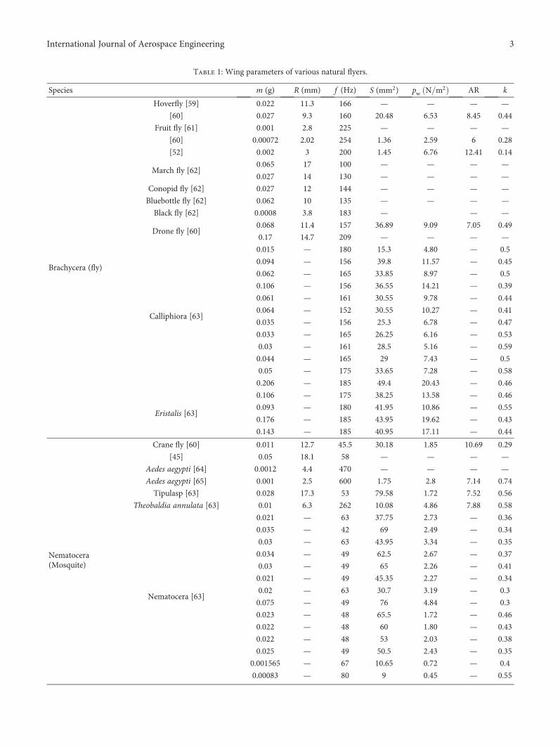
Table 1: Wing parameters of various natural flyers.
Species m (g) R (mm) f (Hz) S (mm2) pw N m2 AR k
Brachycera (fly)
Hoverfly [59] 0.022 11.3 166 — — — —
[60] 0.027 9.3 160 20.48 6.53 8.45 0.44
Fruit fly [61] 0.001 2.8 225 — — — —
[60] 0.00072 2.02 254 1.36 2.59 6 0.28
[52] 0.002 3 200 1.45 6.76 12.41 0.14
March fly [62]0.065 17 100 — — — —
0.027 14 130 — — — —
Conopid fly [62] 0.027 12 144 — — — —
Bluebottle fly [62] 0.062 10 135 — — — —
Black fly [62] 0.0008 3.8 183 — — —
Drone fly [60]0.068 11.4 157 36.89 9.09 7.05 0.49
0.17 14.7 209 — — — —
Calliphiora [63]
0.015 — 180 15.3 4.80 — 0.5
0.094 — 156 39.8 11.57 — 0.45
0.062 — 165 33.85 8.97 — 0.5
0.106 — 156 36.55 14.21 — 0.39
0.061 — 161 30.55 9.78 — 0.44
0.064 — 152 30.55 10.27 — 0.41
0.035 — 156 25.3 6.78 — 0.47
0.033 — 165 26.25 6.16 — 0.53
0.03 — 161 28.5 5.16 — 0.59
0.044 — 165 29 7.43 — 0.5
0.05 — 175 33.65 7.28 — 0.58
0.206 — 185 49.4 20.43 — 0.46
Eristalis [63]
0.106 — 175 38.25 13.58 — 0.46
0.093 — 180 41.95 10.86 — 0.55
0.176 — 185 43.95 19.62 — 0.43
0.143 — 185 40.95 17.11 — 0.44
Nematocera(Mosquite)
Crane fly [60] 0.011 12.7 45.5 30.18 1.85 10.69 0.29
[45] 0.05 18.1 58 — — — —
Aedes aegypti [64] 0.0012 4.4 470 — — — —
Aedes aegypti [65] 0.001 2.5 600 1.75 2.8 7.14 0.74
Tipulasp [63] 0.028 17.3 53 79.58 1.72 7.52 0.56
Theobaldia annulata [63] 0.01 6.3 262 10.08 4.86 7.88 0.58
Nematocera [63]
0.021 — 63 37.75 2.73 — 0.36
0.035 — 42 69 2.49 — 0.34
0.03 — 63 43.95 3.34 — 0.35
0.034 — 49 62.5 2.67 — 0.37
0.03 — 49 65 2.26 — 0.41
0.021 — 49 45.35 2.27 — 0.34
0.02 — 63 30.7 3.19 — 0.3
0.075 — 49 76 4.84 — 0.3
0.023 — 48 65.5 1.72 — 0.46
0.022 — 48 60 1.80 — 0.43
0.022 — 48 53 2.03 — 0.38
0.025 — 49 50.5 2.43 — 0.35
0.001565 — 67 10.65 0.72 — 0.4
0.00083 — 80 9 0.45 — 0.55
3International Journal of Aerospace Engineering

Table 1: Continued.
Species m (g) R (mm) f (Hz) S (mm2) pw N m2 AR k
0.0099 — 262 8.45 5.74 — 0.49
0.001025 — 600 1.2 4.19 — 0.5
0.00189 — 360 2.5 3.70 — 0.46
0.0058 — 277 7.5 3.79 — 0.6
Bee
Orchid bee [66] 0.09 10 214 — — — —
[52] 0.15 13 189 — — — —
[63] 0.82 25 105 — — — —
Honey bee [45] 0.1 9.8 197 30.14 16.6 6.4 0.42
Honey bee [67] 0.1 15.9 197 — — — —
Bumble bee [60] 0.18 13.2 155 54.9 15.6 6.35 0.44
[68] 0.6 22.3 167 — — — —
[67] 0.23 20.7 152 — — — —
[67] 0.23 20.7 140 — — — —
Xylocopa pubescens [33]0.66 10 111.1 63.7 25.53 3.14 0.39
0.72 9.65 111.1 59 29.91 3.16 0.34
Bombus rupestris [33]0.33 8.1 111.1 39.88 20.22 3.3 0.34
0.45 10.4 107.1 53.23 20.81 4.06 0.38
Tipula obsolete [45]0.019 13.7 — 35.92 2.59 10.45 —
0.011 12.7 — 29.51 1.89 10.93 —
Tipula paludosa [45]
0.034 16.2 — 45.29 3.75 11.59 —
0.05 17.4 — 53.82 4.54 11.25 —
0.043 17.2 — 53.59 3.94 11.04 —
Episyrphus balteatus [45]
0.052 10.2 — 23.84 10.6 8.73 —
0.042 10 — 24.21 8.53 8.26 —
0.035 10.2 — 25.59 6.65 8.13 —
0.029 9.7 — 22.46 6.4 8.38 —
0.041 9.9 — 23.17 8.72 8.46 —
0.014 9 — 19.49 3.52 8.31 —
0.027 9.3 — 20.47 6.54 8.45 —
0.028 10 — 25.25 5.46 7.92 —
0.014 7.7 — 14.2 4.9 8.35 —
0.022 9.5 — 21.88 4.98 8.25 —
0.025 9.5 — 21.46 5.8 8.41 —
Eristalis tenax [63]0.068 11.4 — 36.35 9.23 7.15 —
0.11 11.1 — 33.35 16.5 7.39 —
Apis mellifera [63]
0.1 9.8 — 28.5 17.5 6.74 —
0.097 9.5 — 27.14 17.6 6.65 —
0.078 9.3 — 25.78 16.6 6.71 —
0.097 9.6 — 28.01 17 6.58 —
0.087 9.4 — 26.82 15.9 6.59 —
Psithyrus vestalis [63]0.19 14.3 — 63.21 14.6 6.47 —
0.16 13.8 — 57.02 13.5 6.68 —
Bombus terrestris [63]0.22 14.3 — 63.9 17.1 6.4 —
0.23 14.2 — 57.78 22.6 6.98 —
Bombus hortorum [63] 0.23 14.1 — 59.08 18.8 6.73 —
Bombus agrorum [31]0.17 11.4 — 40.05 21.3 6.49 —
0.14 11.4 — 38.28 18.3 6.79 —
Bombus lucorum [63] 0.23 14.1 — 58.22 19.5 6.83 —
4 International Journal of Aerospace Engineering

Table 1: Continued.
Species m (g) R (mm) f (Hz) S (mm2) pw N m2 AR k
German wasp [69] 0.24 16.2 — 66.5 17.68 7.89 —
European hornet [69] 0.6 21.5 — 152 19.25 6.08 —
European hoverfly [69] 0.13 12.68 — 41.3 15.31 7.78 —
Honey bee [69] 0.1 9.95 — 29.9 15.98 6.62 —
Red-tailed bumblebee [69] 0.5 16.5 — 82.5 29.4 6.6 —
Buff-tailed bumblebee [69] 0.39 16 — 71 26.78 7.21 —
Bumblebee [70] 0.18 13 150 53 16 6.6 0.41
Coleoptera(beetle)
Tibicen linnei [33]
1.83 23.51 42.54 361.2 12.41 3.06 0.5
1.85 23.35 44.1 356.5 12.74 3.06 0.51
1.89 24.35 42.3 377 12.3 3.15 0.51
1.81 23.55 42.9 359.55 12.36 3.08 0.51
1.75 23.35 40.5 355.58 12.05 3.07 0.48
1.84 22.95 42.9 357.38 12.61 2.95 0.5
Allomyrina dichotoma [33]
4.29 22.23 37.46 322.14 32.73 3.07 0.25
4.3 22.2 37 320 32.96 3.08 0.25
4.5 24 36.1 366.5 30.11 3.14 0.28
3.79 21.6 35.7 300.7 30.91 3.1 0.24
4.61 22.4 39.5 329 34.36 3.05 0.27
4.24 20.95 39 294 35.31 2.99 0.25
Ladybird [60] 0.034 11.2 54 36.12 4.67 6.95 0.23
Coccinella 7-punctata [63]
0.036 11.7 — 38.18 4.61 7.17 —
0.027 11 — 34.04 3.85 7.11 —
0.024 10.3 — 30.27 3.84 7.01 —
0.034 11.2 — 35.49 4.76 7.07 —
0.031 10.8 — 32.95 4.57 7.08 —
0.597 — 62 222.5 13.15 — 0.4
Coleoptera [63]0.142 — 80 66.5 10.46 — 0.31
0.291 — 78 114.5 12.45 — 0.37
Odonata(dragonfly)
Anax parthenope Julius [69]0.79 71.6 — 995 3.89 10.305 —
0.79 74.7 — 1090 3.55 10.245 —
Damselfly [70]
0.045 29.9 27.5 118 1.86 15.15 0.34
0.046 29.7 31.3 121 1.85 14.55 0.39
0.052 29.1 34.1 115 2.2 14.7 0.38
0.042 29.2 33.1 121 1.74 14.1 0.43
Sympetrum flaveolum [33]
0.37 21.8 34.8 415.6 2.2 2.28 1.05
0.33 21.65 38.5 416.4 1.97 2.26 1.24
0.37 20.6 37.9 387.4 2.31 2.2 1.07
0.31 20.95 35.3 370.1 1.93 2.22 1.04
Aeschna juncea [71]0.75 47.4 — 386.4 4.15 11.63 —
— 46 — — 4.15 8.4 —
Odonata [72]
0.092 23.5 41 193.5 2.33 5.71 0.58
0.101 27 44 255 1.94 5.72 0.78
0.137 27.9 41 272.5 2.46 5.71 0.67
0.102 22.5 41 177 2.82 5.72 0.51
0.077 22.2 41 172.5 2.19 5.71 0.56
0.09 25.4 46 226 1.95 5.71 0.77
0.091 25.4 41 226 1.97 5.71 0.68
5International Journal of Aerospace Engineering

Table 1: Continued.
Species m (g) R (mm) f (Hz) S (mm2) pw N m2 AR k
Butterfly
Battus polydamas [60] 0.45 53 12.4 1682.04 1.33 3.34 0.69
Papilio thoas [29] 0.42 58.4 9.5 1937.82 1.07 3.52 0.63
Parides childrenae [29] 0.37 46.1 12 1101.15 1.66 3.86 0.48
Aphrissa boisduvalii [29] 0.14 32.5 13.7 1010.77 0.67 2.09 0.82
Itaballia demophile [29] 0.089 28.4 11.7 653.09 0.66 2.47 0.57
Archaeoprepona demophon [29] 1.06 60.4 8.9 2634.05 1.97 2.77 0.51
Myscelia cyaniris [29] 0.091 31.6 9.1 715.82 0.62 2.79 0.48
Pyrrhogyra naearea [29] 0.11 30.6 10.7 796.9 0.69 2.35 0.57
Siproeta stelenes [29] 0.24 40.9 10.7 1203.46 0.98 2.78 0.58
Dryas iulia [29] 0.18 44.1 13.9 764.17 1.12 5.09 0.55
Janatella leucodesma [29] 0.024 18.1 13.3 246.32 0.48 2.66 0.47
Morpho amathonte [29] 0.33 70.3 6.4 3594.25 0.45 2.75 0.89
Morpho peleides [29] 0.36 60.5 6.9 2815.58 0.62 2.6 0.72
Caligo illioneus [29] 1.04 74.3 9.6 4907.1 1.05 2.25 1.02
Pierella luna [29] 0.077 35.1 13.7 772.42 0.49 3.19 0.84
Ochlodes [33] 0.13 9.87 56.97 112.25 2.94 1.74 0.79
Pieris rapae [33]
0.037 12.1 12.8 203.75 0.4 1.44 0.6
0.039 12.1 9.9 229.35 0.42 1.28 0.51
0.042 11.4 12.7 225.35 0.46 1.15 0.62
0.03 12.8 11.7 219 0.34 1.50 0.65
0.05 12.3 13.1 253 0.49 1.20 0.66
0.04 11.94 12.04 231.09 0.42 1.23 0.61
Plusia gamma [33]
0.06 7.35 43.5 60 2.43 1.80 0.47
0.095 8.4 44.8 84 2.77 1.68 0.54
0.095 8.25 50.8 83.2 2.8 1.64 0.61
0.065 8 47.6 72.85 2.2 1.76 0.6
0.079 8 46.68 75.015 2.55 1.71 0.55
Ochlodes [33]
0.13 9.55 56.6 110.95 2.78 1.64 0.77
0.15 10.15 57.7 115 3.15 1.79 0.76
0.13 9.9 56.6 110.8 2.89 1.77 0.77
Scarce swallowtail [73] 0.38 36.99 — 1800 0.82 1.52 —
Large white [73] 0.15 31.01 — 920 0.68 2.09 —
Small heath [73] 0.05 15.99 — 240 0.94 2.13 —
Hawkmoth
[12]
1.12 45.6 26.1 — — — —
1.83 43.5 25.9 — — — —
1.58 48.5 26.1 891 8.93 5.28 0.41
1.65 51.9 26.3 953.5 8.53 5.65 0.43
2 52.1 25.4 983.5 10.33 5.52 0.39
[74]
1.41 49.7 28 994 6.95 4.97 0.52
1.51 53.1 29 1067.3 6.93 5.28 0.56
1.29 51.6 31 1021.7 6.19 5.21 0.62
1.47 50.8 27 909.3 7.92 5.68 0.45
Emmelina monodactylus [45] 0.0084 11.1 — 42.56 0.97 5.79 —
Manduca sexta [45]
1.32 51.8 — 981.1 6.6 5.47 —
1.58 48.7 — 817.8 9.5 5.8 —
1.39 46 — 759.8 8.96 5.57 —
1.34 51.8 — 918.9 7.17 5.84 —
[73] 1.69 48.51 — 900 9.2 5.23 —
6 International Journal of Aerospace Engineering

Table 1: Continued.
Species m (g) R (mm) f (Hz) S (mm2) pw N m2 AR k
[75] 1.67 49 25 891 9 5.3 0.38
Giant peacock moth [73] 2.19 74.5 — 6000 1.54 1.85 —
Death’s-head hawkmoth [73] 1.67 51.02 — 1025 7.65 5.08 —
Hummingbird hawkmoth [73] 0.29 21.3 — 189.5 7.29 4.79 —
Bats
Soricina [76]10.1 115 — 4266 11.3 6.2 —
9.5 115 — 4266 10.8 6.2 —
Yerbabuenae [76]21.6 167.5 — 7903 13.4 7.1 —
23.6 161.5 — 7671.25 15.1 6.8 —
Glossophaga soricina [77] 11 119.72 — 4550 11.9 6.3 —
Glossophaga soricina [78] 10.5 120.96 — 4645 11.2 6.3 —
Leptonycteris yerbabuenae [79] 22.6 164.8 — 7760 14.2 7 —
Cynopterus brachyotis [79] 30.7 197.55 — 11,650 13.14 6.7 —
Pelcotus auritus [79] 9 134.69 — 6150 7.18 5.9 —
Rousettus aegyptiacus [79]118.3 276.42 — 28,300 20.5 5.4 —
118.3 230.5 — 19,950 29.1 5.34 —
Tadarida brasiliensis [79] 11.8 131.04 — 3504 16.5 9.8 —
Chalinolobus gouldii [80] 13.4 173.06 9.04 8940 7.35 6.7 0.49
Chalinolobus morio [80] 7 144.01 10.91 6755 5.08 6.14 0.62
Chalinolobus nigrogriseus [81] 6.5 139.05 11.27 6090 5.24 6.35 0.6
Hipposideros ater [32] 4.4 124.46 10.91 5305 4.07 5.84 0.61
Macroderma gigas [32] 130 379.56 6.96 47,390 13.44 6.08 0.64
Miniopterus schreibersii [32] 10.1 170.42 9.1 8370 5.91 6.94 0.53
Mormopterus planiceps [80] 8.6 131.84 9.34 4795 8.69 7.25 0.34
Nyctophilus arnhemensis [81] 7.1 150.71 11.43 7805 4.46 5.82 0.74
Nyctophilus geoffroyi [32] 5.7 131.73 10.94 6110 4.74 5.68 0.62
Nyctophilus gouldi [82] 10 152.43 10.4 7985 6.14 5.82 0.58
Nyctophilus timoriensis [80] 11 161.01 10.56 8670 6.22 5.98 0.61
[32] 14.2 174.81 11.08 10,135 6.88 6.03 0.66
Pteropus poliocephalus [32] 700 668.83 3.4 129,100 26.59 6.93 0.37
Pteropus scapulatus [32] 412 552.87 4.15 82,500 24.5 7.41 0.37
Rhinonycteris aurantius [32] 8.6 153.94 9.76 7535 5.6 6.29 0.56
Saccolaimus flaviventris [83] 46.2 287.49 8.36 19,725 11.49 8.38 0.54
Scotorepens balstoni [80] 8 133.09 11.31 5650 6.95 6.27 0.5
Scotorepens greyii [81] 7 125.02 11.59 5050 6.8 6.19 0.49
Tadarida australis [80] 35.3 231.28 8.19 12,920 13.4 8.28 0.39
Taphozous georgianus [81] 28.1 233.22 8 14,055 9.81 7.74 0.47
Taphozous hilli [32] 24.1 230.83 7.47 13,680 8.64 7.79 0.46
Vespadelus finlaysoni [83] 5.6 127.5 10.68 5210 5.27 6.24 0.52
Vespadelus regulus [80] 4.7 116.76 10.75 4455 5.17 6.12 0.49
Egyptian fruit bat [84] 104 265 — 23,250 22 6.04 —
Minor epauletted fruit bat [84] 50.36 200 — 14,500 18 5.52 —
Common pipistrelle [84] 5.3 104.5 — 3250 8 6.72 —
Common noctule [84] 26.5 172 — 8050 16 7.35 —
Northern bat [84] 9.9 138.5 — 5750 8.4 6.67 —
Parti-coloured bat [84] 14.12 149 — 6100 11 7.28 —
Brown long-eared bat [84] 9 135 — 6150 7.2 5.93 —
Large-eared free-tailed bat [84] 35.58 224.5 — 10,850 16 9.29 —
7International Journal of Aerospace Engineering

Table 1: Continued.
Species m (g) R (mm) f (Hz) S (mm2) pw N m2 AR k
Hummingbirds
Blue-throated [85] 8.4 85 23.3 1763 23.5 8.2 0.31
Magnificent [85] 7.4 79 24 1486 24.7 8.4 0.29
Black-chinned [85] 3 47 51.2 622.3 23.5 7.1 0.41
Rufous [85] 3.3 42 51.7 476.8 33.6 7.4 0.3
[86] 3.2 46.1 — 599.2 36.7 7.1 —
[87]
4.24 45 53.25 494 42.11 8.2 0.28
4.24 48 49.1 584 35.61 7.89 0.31
4.1 51 47.3 668.5 30.08 7.78 0.35
4.54 52 42.57 662.5 33.6 8.16 0.29
Anna (male) [88] 4.52 54.5 45.9 714 31.02 8.32 0.34
[89]
5.6 50 — 588.2 — 8.5 —
5 50 — 543.5 — 9.2 —
4.7 59 — 838.8 — 8.3 —
Broad-tailed [87]
4.22 55 41.32 780.5 26.52 7.75 0.35
3.46 54 36.38 736.5 23.05 7.92 0.32
3.66 55 38.71 748 24.01 8.09 0.34
5.16 57 39.25 799.5 31.67 8.13 0.31
3.6 52 39.53 680.5 25.96 7.95 0.31
3.61 56 37.17 817.5 21.66 7.76 0.35
3.93 55 38.1 860.5 22.4 7.03 0.37
4.1 57 37.94 837.5 24.02 7.76 0.35
Ruby-throated (male) [90]
3.58 41 — 460 38.4 7.34 —
3.67 41 — 485 37.3 6.96 —
4.01 40 — 445 44.1 7.17 —
4.16 43 — 455 44.9 8.13 —
Ruby-throated (female) [90]
4.36 49 — 635 33.6 7.55 —
4.36 48 — 640 33.3 7.18 —
4.18 49 — 600 34.2 8 —
Amazilia fimbriata [91] 5.1 58.5 35 850 29.4 8.05 0.29
Aglaiocercus kingi smaragdinus [92] 4.65 61.2 21.7 988.9 23.34 7.58 0.22
Chrysuroniaoerumejosephine [92] 4.6 54.1 32.8 748 30.35 7.82 0.25
Lophomis delattrei [93] 2.79 40.3 50.7 394.8 34.5 8.23 0.27
Phaethornis ruber [93] 2.64 40.7 40 484 27.2 6.83 0.26
Giant hummingbird (male) [93] 22.6 143 13 4508.4 24 9.1 0.27
(female) 19.6 139.7 13.9 4307.8 21.5 8.3 0.3
Birds
Hypoleuca [76]
14.8 117.63 — 5293.43 13.7 5.2 —
14.1 116.31 — 5234.09 13.2 5.3 —
13.7 118.4 — 5327.78 12.6 5.2 —
Atricapilla [76] 16.3 120.58 — 5546.53 14.4 5.2 —
Adean condor [94] 11,700 1490 — 562,500 99.96 7.9 —
Great bustard [94] 8950 1738 — 794,850 54.88 7.6 —
Wandering albatross [94] 8500 1703 — 310,300 134.26 18.7 —
[94] 8877.6 — — 310,000 140 — —
Griffon vulture [94] 7270 1278 — 527,000 67.62 6.2 —
Brown pelican [94] 2650 1058 — 228,450 56.84 9.8 —
Seagull [94] 1915 867.4 — 136,800 68.6 11 —
White-fronted goose [94] 1715 703.5 — 91,650 91.14 10.8 —
American black vulture [94] 1702 705 — 150,600 54.88 6.6 —
8 International Journal of Aerospace Engineering

2.2. Wing Loading. Wing loading is an important parameteron the flight mechanism of flyers, which is defined as theweight of flyer divided by the total wing surface area and isexpressed as follows:
pw =mgA
~V2t ~ l ~m1/3, 5
where pw is wing loading (N/m2).
Wing loading varies with the size and is proportional tothe third root of the body mass and as a result inclining tobe larger in larger animals and artificial flyers. Also, it hasan equivalent unit of pressure. Therefore, it also presentsthe pressure force over the wing and is proportional to thesquare of the flight speed, which indicates that flyers withlow wing loadings are able to fly in low speed. Meanwhile,(5) indicates that flyers with larger weight have larger wingloading and have to fly fast. Additionally, manoeuvrability
Table 1: Continued.
Species m (g) R (mm) f (Hz) S (mm2) pw N m2 AR k
Pheasant [94] 1660 428.4 — 79,800 101.92 4.6 —
Serpent eagle [94] 1655 909.7 — 206,900 39.2 8 —
Frigate bird [94] 1620 1010 — 162,000 49 12.6 —
Velvet scoter [94] 1578 484.6 — 50,500 152.88 9.3 —
Black-throated loon [94] 1495 599 — 59,800 122.5 12 —
Herring gull [94] 1189 728.5 — 106,150 54.88 10 —
Mallard [94] 1100 446.7 — 46,400 117.6 8.6 —
Red kite [94] 927 807.4 — 144,850 31.36 9 —
Peregrine falcon [94] 712 505 — 57,300 60.76 8.9 —
Carrion crow [94] 470 451.3 — 52,900 43.12 7.7 —
Pigeon [94] 330 316.2 — 31,750 50.96 6.3 —
Jackdaw [94] 253 353.4 — 33,300 37.24 7.5 —
Long-eared owl [94] 247 471.2 — 54,150 22.54 8.2 —
Kestrel [94] 245 367.1 — 35,000 34.3 7.7 —
Montagu’s harrier [94] 237 553.1 — 65,100 17.64 9.4 —
Gray plover [94] 216 327.7 — 20,650 50.96 10.4 —
Magpie[94] 214 297.8 — 32,250 32.34 5.5 —
Little grebe [94] 180 220 — 11,800 74.48 8.2 —
Merlin falcon [94] 173 303.7 — 20,500 41.16 9 —
House sparrow [94] 30 123.1 — 5050 29.4 6 —
Swift [94] 17 210.2 — 5200 16 17 —
House martin [94] 14 147 — 4650 15.68 9.3 —
Pied flycatcher [94] 12 116.5 — 4600 12.74 5.9 —
Citril finch [94] 12 122.4 — 3700 15.68 8.1 —
Stone chat[94] 12 108.4 — 3850 14.7 6.1 —
Wren [94] 10 88.1 — 2250 23.52 6.9 —
Gold crest [94] 4 71 — 1600 11.76 6.3 —
Common tern [35] 117.3 — — 25,000 23 — —
Dove prion [35] 173.5 — — 23,000 37 — —
Black-head gull [35] 234.7 — — 37,500 31 — —
Black skimmer [35] 306.1 — — 44,000 34 — —
Common gull [35] 374.5 — — 57,500 32 — —
Kittiwake [35] 398 — — 50,500 39 — —
Royal tern [35] 479.6 — — 54,000 44 — —
Fulmar [35] 836.7 — — 62,000 66 — —
Herring gull [35] 959.2 — — 90,500 52 — —
Great skua [35] 1377.6 — — 107,000 63 — —
Great black-backed gull [35] 1959.2 — — 136,000 71 — —
Sooty albatross [35] 2857.1 — — 170,000 82 — —
Black-browed albatross [35] 3877.6 — 180,000 106 — —
9International Journal of Aerospace Engineering

depends on wing loading, because it depends on the min-imum radius of turn which is proportional to the bodymass [37, 38]. In other words, manoeuvrability rises withwing loading decrease. Therefore, we could see that air-craft utilized in aerobatics has small wide wings with lowwing loading.
2.3. Aspect Ratio. Aspect ratio is a parameter of the wingperformance of flyers and a measure of the wing shape (wingslenderness along the spanwise). It is defined as the square ofthe wingspan over the wing pair surface, which is presentedas follows:
AR =2R 2
2S=2R2
S~l2
l2~m0 6
It can be rewritten as
AR =2R2
S≈
2R2
mg/2pw≈
4R2
mgpw 7
From (6), it is observed that the aspect ratio does not varywith body mass, a dimensionless number. In (7), it presentsthat the aspect ratio can indicate the flight characteristics offlapping animals. The aspect ratio in hummingbirds is almostindependent on size, whereas for other species the aspectratio increases slightly with size. Details are available in [39].
In general, flyers with small aspect ratio have high agilityas well as maneuverability, whereas a high aspect ratio wingcontributes to a low induced drag, which facilitates a glidingand slow flapping flight. The induced drag caused by the lifttends to decrease with increasing aspect ratio. That is,induced drag is generally regarded to be inversely propor-tional to the aspect ratio. Therefore, the longer wing it is,the smaller induced drag is obtained. Impliedly, the glideratio (the lift-to-drag ratio) rises with aspect ratio increase[39]. For instance, the aspect ratio of hummingbirds(approximately 6.5~9.5) is less than that of albatross (around15), so albatrosses fly in gliding mode mostly, while hum-mingbirds are capable of hovering. Besides, increasing theaspect ratio will enhance the lift coefficient when the angleof attack is constant. Therefore, aerodynamic performancecan be enhanced by increasing the aspect ratio. The higherthe aspect ratio is, the longer and thinner the wing is. How-ever, long wings are not always beneficial. It not only inducesdrag due to wingtip vortices but also is more vulnerable tobreak the wing. At the same time, the long wing might benegative to ground take-off.
Therefore, the different combinations of wing loadingand aspect ratio allow a natural flyer to adopt particular flightpattern and foraging strategies [40]; see Figure 1. Forinstance, species of high wing loading and high aspect ratio,particular for short wing, usually fly fast and considerableinexpensive. Therefore, commuting and migrating speciesare usually adapted to such flight mode like swans, geese,and loons [41]. By contrast, flyers with low wing loadingand low aspect ratio usually have a broad slotted wingtipsince such kind of wingtip can act to delay stall and decline
induced drag, avoiding too large wingtip vortices and risesto lift [42]. Otherwise, a smaller aspect ratio leads to highinduced drag. Then, flying species with a high wing loadingand low aspect ratio require very high energy cost such as gal-linaceous, so they spend more time on the ground. Suchkinds of animals have almost lost their flight capability suchas penguins [43] (Penguin’s wings might evolve into finsfor swimming so as to adapt environmental conditions.)However, flyers that have low wing loading (large wing area)and high aspect ratio, particularly for flyers with small weightand long wing, fly slowly and inexpensively such as swallowsand swifts. Certain natural flyers like bees, hummingbirds,and certain bats fly at unsteady flow environment and havea medium aspect ratio and wing loading. They are adaptedto flight in hovering and foraging fly continuously in openspaces. Figure 1 (left) shows the aspect ratio plotted againstwing loading for various natural flyers. From Figure 1 (right),we found that the butterfly has lower wing loading and aspectratio than that of other species. In modern natural flyers, theaspect ratio ranges from 1.15 in some butterfly (Pieris rapae)to 18 (or higher) in wandering albatross. Besides, certainmodern flyers have a similar combination of aspect ratioand wing loading, similarly to natural flyers. For instance,the space shuttle has a similar aspect ratio of butterflies withlow wing loading. Boeings have a similar aspect ratio ashummingbirds.
Since wing loading and aspect ratio are widely appliedto quantify the size and shape in aircraft engineering andstudies of animal flight, here, the pw −AR ratio is proposedas the ratio of wing loading to aspect ratio, and it isassumed A ≈ 2S in N m2
pw −AR ratio,pwAR
=mg/A2R2/S
≈mg2S
∙S
2R2 =mg
4R2 ,8
It is observed that the pw −AR ratio has the same phys-ical unit of wing loading, so the pw −AR ratio may have thesame physical meaning of wing loading. The pw −AR ratiopresents the combination of wing loading and aspect ratioto evaluate the wing performances, which may be an evalu-ated performance index. Therefore, it may also be appliedto assess the wing performances.
2.4. Flapping Wing Lift Production. To roughly estimate theeffect of wing geometry parameters on the average lift force,a classical steady flow theory is employed when using cycleaveraged quantities. The average lift force can be approxi-mately presented as
FL =12ρCL 2S U2
CP = ρCLSU2CP 9
It can be rewritten as
FLS
= ρCLU2CP 10
10 International Journal of Aerospace Engineering

Therefore,
UCP ~FLS
1/2
~ l 1/2 ~ m 1/6, 11
where UCP is the average velocity at pressure centre, which
can be expressed as UCP = FL/S /ρC2L and CL is the aver-
age lift coefficient which depends on wing geometry andattack angle variation over one wingbeat under the assump-tion of quasi-steady [44].
Assuming a flat and rigid wingwith lengthR, the spanwiselocation of the pressure centre is given by the nondimensionalradius of the second moments of wing areas r2 S , whichranges between 0.5 and 0.6 in most insects [45]. For thehomogeneous pressure distribution on the whole wing, thesecond moment of the wing area coincides with the centreof pressure. Moreover, Lua et al. proved that the velocity atthe secondmoment of the wing area can be selected as the ref-erence velocity for flapping wings [46]. For simplicity, weassume RCP = R/2. Then, the average velocity at the pressurecentre can be presented as
UCP = 2ϕf RCP = ϕf R, 12
f =UCPϕR
~l 1/2
l= l −1/2 ~ m −1/6, 13
where f is a wing flapping frequency (Hz) and ϕ is theflapping amplitude angle (deg).
Based on a combination of (6), (9), and (12), thecycle mean lift force of a pair of flapping wings can bereorganized as
FL =12ρCLAR Sϕf 2 14
In (14), the average lift force is altered approximatelylinearly with CL and AR, but quadratically with the wingsurface, flapping amplitude, and flapping frequency.
From the lift coefficient perspective, (14) can berewritten as
CL =2FL
ρAR Sϕf 2 15
2.5. Wing Lumped Parameter. Equation (14) indicates therelation of average lift force with the four variables suchas AR, wing surface, flapping amplitude, and flappingfrequency. This equation can be used to assess and guidewing design [20] but is unable to estimate the relationof wingbeat frequency with the four parameters (AR,wing surface, body mass, and flapping amplitude angle)because they are independent. Therefore, studying therelation between flapping frequency and body morphol-ogy (i.e., total wing surface and body mass) is indispens-able. Corben [31] exhibited the relationship betweenflapping frequency and total wing surface A and bodyweight based on the nondimensional analysis, which isexpressed as
100 101
Wing loading (N/m2)
Asp
ect r
atio
101
100
102
FlyMosquitoBeeBeetleDragonfly
ButterflyHawkmothBatHummingbirdBird
0
50
100
Aver
age-
SDSpecies
Wing loading
Fly
Mos
quito Be
e
Beet
le
Dra
gonfl
y
Butte
rfly
Haw
kmot
h
Bat
Hum
min
gbird Bird
Aspect ratio
Figure 1: Aspect ratio vs. wing loading in natural flyers (left), and average value with standard deviation (SD) of wing loading and aspect ratio(right).
11International Journal of Aerospace Engineering

f =kA
mgρ
=kA
gρ
1/2m = 2 86
kA
m, 16
where the dimension of 2.86 is m4/s2kg.Therefore, the wing lumped parameter k can be
expressed as
k =f A
2 86 m~m−1/6m2/3
m−1/2 =m0 17
Combination of (15) and (16) and the assumption of FL=mg in relation to the wing lumped parameter with meanlift coefficient and AR can be presented as
k =2 2
CL∅ AR=
2 s
CL∅R18
The lumped parameter is also a dimensionless number.From (17), it is clearly seen that it does not vary with the bodymass. As is shown in (18), the lumped parameter is inverselyproportional to the average lift coefficient, which indicatesthat the larger the lumped parameter is, the less lift is pro-duced at a constant angle attack. Additionally, the largerthe lumped parameter is, the shorter and rounded the wingis. This is because the lumped parameter is also inversely pro-portional to the aspect ratio. Therefore, the lumped parame-ter may also be interpreted as a measure of aerodynamicefficiency, and the lumped parameter k may be used tosupervise wing design.
The power functions of wing parameters and mass aresummarized in Table 2 based on geometric similarity. Wecan see that the aspect ratio (AR) and the lump parameter(k) are independent on the mass, and the flapping frequencyand wing loading are proportional to m1/6 and m1/3, respec-tively. Table 2 only shows the mathematical correlation whilehaving no physical meaning.
3. Scaling Law, Results, and Discussion
In this section, the scaling laws induced from the regressionanalysis of species (insects, bats, hummingbirds, and otherbirds) are established through statistical analysis. The rela-tion between weight and parameters of aerodynamic perfor-mance can be determined so that the relationship of differentparameters, such as wing surface, wing length, flapping fre-quency, AR, lumped parameter, wing loading, and bodymass, with aerodynamic performance can be predicted toMAV design. In other words, this concept provides rules todesign and compare flying objects of different sizes andweight in different orders of magnitudes.
Many scholars conducted some similar studies, but nocomprehensive and relevant works were done. Greenewalt[47] presented the earliest correlations linked with wingspan,wing surface, and mass among different bird species; how-ever, the wing loadings were not provided. Likewise, a similarcorrelation on wingspan against mass and flapping frequencyagainst mass was studied by Norberg [48]. Pennycuick[49] showed the database by fitting the date for different
species of birds and bats and then studied the correlationamong flapping frequency, body mass, and wing area. How-ever, no comprehensive studies were conducted especiallyfor the aspect ratio and lumped parameter. Therefore, thissection examines the flow regime effects on body mass,flapping frequency, wing surface, wing loading, AR, andlumped parameter.
3.1. Wing Surface, Flapping Frequency, and Wing Length.The initial study objective is to assess the effect of wing sur-face, flapping frequency, and wing length. Wing geometriesare varied during flapping. That is, the projected wing areaand length are changed when flapping [36], which directlyimpacts on the lift or drag. To keep balance, the airfoil shapeand posture of the body are also varied. To find the relationof wing surface and flapping frequency as a function of bodymass and wing length, various species and data are surveyed.A summarized plot of the relation among wing surface,mass, and wing length is firstly presented in Figure 2. Theoptimal fitting of the wing surface is also provided in redcolor. From the figure, it is clearly seen that the data arehighly intensive with an excellent general trend. In otherwords, the wing surface is proportional to both mass andwing length in a log–log domain. In Figure 2, the mass offlyers ranges from 0.7mg to 3.8 kg. The rudimentary analysisshows that natural flyers in general track follow the rules.The relation between wing single surface and the mass ofnatural flyers can be expressed as follows:
S = 430 29m0 77 19
The relation between single wing surface and wing lengthis shown in Figure 2 (right); the equation can be written as
S = 0 81R1 81 20
Figure 3 shows the flapping frequency related to bodymass and wing length, respectively. Figure 3 (left) revealsthe relation betweenflapping frequency andmass. The generaltrend is presented with an inverse proportion in the log–logdomain, which can be roughly expressed as
f = 40 63m−0 29 21
The relation between flapping frequency and wing lengthis shown in Figure 3 (right), and the fitted equation can bestill roughly written as
f = 740 31R−0 82 22
As shown in Figure 3, high frequency is an option ofinsects or small birds such as hummingbirds, but not oflarger birds, because their bones cannot bear the stress causedby a heavier inertial load. Smaller birds, bats, and insects arelikely to choose higher frequency because of the decreasedinertial loading within the limited breaking stress of theirhollow bones. Also, the data in Figure 3 is slightly scattered;this might result from their distinct flight pattern of differentspecies. From (19) to (22), we can see that the wing surface
12 International Journal of Aerospace Engineering

Table 2: Power function of wing parameters against body mass. The exponent of correlations is for (mass)exponent.
Wing parameters R c S pw AR k UCP f
Dimensions (mm) (mm) (mm2) (N/m2) — — (m/s) Hz
Exponent of correlation m1 3 m1/3 m2/3 m1/3 m0 m0 m1/6 m1/6
10−4 10−3 10−2 10−1 100 101 102 103 104 10510−3
10−2
10−1
100
101
102
103
104
105
106
107
Win
g su
rface
(mm
2 )
Mass (g)
Fitted line
FlyMosquitoBeeBeetleDragonflyButterfly
HawkmothBatHummingbirdBird
10−3
10−2
10−1
100
101
102
103
104
105
106
107
Win
g su
rface
(mm
2 )
100 101 102 103 104
Fitted line
Wing length (mm)
FlyMosquitoBeeBeetleDragonflyButterfly
HawkmothBatHummingbirdBird
Figure 2: The relation of wing surface vs. mass (left), and wing surface vs. wing length (right).
Flap
ping
freq
uenc
y (H
z)
10−3
10−2
10−1
100
101
102
103
104
10−4 10−3 10−2 10−1 100 101 102 103 104 105
Mass (g)
Fitted line
FlyMosquitoBeeBeetleDragonflyButterfly
HawkmothBatHummingbirdBird
Flap
ping
freq
uenc
y (H
z)
100 101 102 103 104
Fitted line
Wing length (mm)
FlyMosquitoBeeBeetleDragonflyButterfly
HawkmothBatHummingbirdBird
10−3
10−2
10−1
100
101
102
103
104
Figure 3: The relation of flapping frequency vs. mass (left), and flapping frequency vs. wing length (right).
13International Journal of Aerospace Engineering

increases with their body mass and the wing length increases,while the flapping frequency decreases with their body massand the wing length increases.
The relationship between wing length and body mass isshown in Figure 4. In this figure, it is observed that the dataof natural flyers are intensive and track the following ruleand the wing length is positively proportional to the bodymass. The equation of the dashed line of all species is
R = 43 31m0 39 23
According to the preceding equation, the relationshipamong wing area, wing length, flapping frequency, and bodymass are clearly and easily observed, although data inFigure 3 are not much intensive. Therefore, the conclusionfrom the above observations indicates that the general lawsrelated to wing surface, wing length, flapping frequency,and body mass exist and can be applied to guide the wingdesign of flapping wing MAVs.
3.2. Wing Loading, Aspect Ratio, and Lumped Parameter.Wing loading is an important parameter when studying flightmechanisms in flyer science. Wing loading analyzes theopposing action of two category forces, such as gravitationaland inertial forces, and the aerodynamic forces to generate liftand thrust. Wing loading pw mainly represents the wing flap-ping effect of a flyer. The relation of wing loading with bodymass and wing length is shown in Figure 5. Generally, thewing loading rises with the mass increase, which is theresponse to (5). This is really the case for certain species suchas bat (pw ~m0 29), whereas other species may not follow thisrule such as hummingbirds (pw ~m−0 16). A similar result wasalso presented in [43]. The data in Figure 5 are moderatelyscattered, which might be related with the aerodynamic andstructural factors. For instance, birds use pectoral musclesto perform downstroke motions and supracoracoideus mus-cles for upstroke motions [50], whereas insects or bats havedifferent movements. Besides, it is clearly seen that the wingloading in butterfly is smaller than that of other species, whichmay be linked that they have a relatively larger wing surface.The data from other species are also mildly intensive (exceptbutterfly). The slope of the interpolating straight line can beobtained, showing an acceptable performance. The equationof the straight line is
pw = 10 85m0 25 24
The relation between wing loading and wing length is pre-sented in Figure 5 (right), and the corresponding equationcan be expressed as
pw = 1 52R0 55 25
From (24) and (25), we also know that the wing loadingrises with increasing their body mass and wing length.
Aspect ratio AR and the lumped parameter k are alsoessential parameters that are directly related to thewing shape,such as the wing length, and wing surface thereby affectingthe aerodynamic performance. Aerodynamic performance
can be enhanced by making the wings longer and thinner.This is the reason why high performances of gliders have anearly 20 aspect ratio, whereas aircrafts applied in aerobaticspossess short broad wing for high manoeuvrability.
As previously mentioned, the aspect ratio is indepen-dent of size in geometric similarity analysis. However, theratio for other species excluding hummingbirds risesslightly in size. Similarly, the lumped value is also constantbased on (17). In this study, the average value of variousspecies is considered and studied. From (18), it can beobserved that the aspect ratio and lumped parameter arein inverse proportion, which indicates that the species withhigh aspect ratio have a lower lumped parameter. The rela-tionship of AR and lumped parameter k with body massand wing length are plotted in Figures 6–8. Figure 6 (left)shows AR against mass, whereas Figure 6 (right) indicatesthe relation of AR and wing length for various naturalflyers. From Figure 6, it is found that the data of speciesexcept for butterfly is intensive and consistent around theaverage value. Nevertheless, both figures evidently show anobtained average aspect ratio which is approximately 7.16for all species presented in this paper, except for butterflies.The performance of butterflies may be caused by uniquewing structure, relative large wing surface, and flappingwing motion.
In Figure 7 (left), the relation of k andmass is shown, andin Figure 7 (right), the relation between k and wing length isalso exhibited. All data is well distributed and close to theaverage value of 0.48, which indicates that lumped parameterk may constantly be free from the mass and wing length fornatural flyers. Therefore, according to the lumped parameterk and (13) and (15), the relation of flapping frequency, wingtotal surface, and mass can be established. Furthermore, therelationship of wing single surface, lift coefficient, flapping
10−4 10−3 10−2 10−1 100 101 102 103 104 105
Mass (g)
Fitted line
FlyMosquitoBeeBeetleDragonflyButterfly
HawkmothBatHummingbirdBird
Win
g le
ngth
(mm
)
10−3
10−2
10−1
100
101
102
103
104
Figure 4: Relation of wing length vs. mass.
14 International Journal of Aerospace Engineering

amplitude, aspect ratio, and wing length can be roughlyobtained as well.
In this section, a comprehensive study is performedregarding the aspects of wing length, wing surface, bodymass, and flapping frequency, specifically for the aspect ratioand lumped parameter k of natural flyers, which is summa-rized in Table 3 for each species. The aspect ratio and lumpedparameter for each species are presented in mean value withstandard deviation. The data is of 0.01 precision. New
findings are valuable and useful. The average aspect ratio inthe natural flyer excluding butterflies is nearly 7.16, and theaverage lumped parameter in the natural flyers is approxi-mately 0.48. The aspect ratio and lumped parameter corre-sponding to the species are presented in Figure 8. It isfound that the butterfly has a low aspect ratio and highlumped value k. In short, the summarized relation presentedin Table 3 provides a reference when designing flapping wingMAVs inspired by natural flyers.
Win
g lo
adin
g (N
/m2 )
10−3
10−2
10−1
100
101
102
103
104
10−4 10−3 10−2 10−1 100 101 102 103 104 105
Mass (g)
Fitted line
FlyMosquitoBeeBeetleDragonflyButterfly
HawkmothBatHummingbirdBird
100 101 102 103 104
Fitted line
Wing length (mm)
FlyMosquitoBeeBeetleDragonflyButterfly
HawkmothBatHummingbirdBird
Win
g lo
adin
g (N
/m2 )
10−3
10−2
10−1
100
101
102
103
104
Figure 5: The relation of wing loading vs. mass (left), and wing loading vs. wing length (right).
10−4 10−3 10−2 10−1 100 101 102 103 104 105
Mass (g)
Fitted line
FlyMosquitoBeeBeetleDragonflyButterfly
HawkmothBatHummingbirdBird
10−3
10−2
10−1
100
101
102
100 101 102 103 104
Fitted line
Wing length (mm)
FlyMosquitoBeeBeetleDragonflyButterfly
HawkmothBatHummingbirdBird
Asp
ect r
atio
Asp
ect r
atio
10−3
10−2
10−1
100
101
102
Figure 6: Relation of aspect ratio vs. mass (left), and aspect ratio vs. wing length (right).
15International Journal of Aerospace Engineering

Due to the less survey numbers, the power functions offlapping frequency and lump parameter against body massfor bird are not given. Also, the butterfly has a lower aspectratio and higher lumped value compared with other species,which is opposite to that of hummingbirds. Interestingly,the power function of wing loading for hummingbirds is
entirely different from other species. Also, Table 3 only showsthe mathematical relation while having no physical meaning.
3.3. Wing Design and Manufacture for Flapping Wing MAVs.Based on the study above, the relations among differentparameters are presented and summarized in Table 3. In thissection, the existing flapping wing MAVs are added for com-parison. The morphological parameters of flapping wingMAVs are shown in Table 4. Here, the relation of wing sur-face and wing length against mass as well as lumped param-eter against aspect ratio including flapping wing MAVs areseparately discussed and studied as examples.
According to the relation between single wing surface,wing length, and the mass of natural flyers, it is observedthat the size of MAVs obeys such rule; see in Figure 9. Cur-rently, the existing flapping wing MAVs are nearly in therange of corresponding species, in which the size of KUBee-tle is close to the size of giant hummingbird, whereas the sizeof Maryland-Hummingbird, DelFly-II, and TL-FlowerFlyare in the scope of Bat. They are highlighted in black withdots. Figure 10 reveals the relation lumped parameter andaspect ratio in all flyers including natural and manufacturedflyers. From Figure 10, we can observe that the lumped valuek of Bee and Hummingbird is lower than the average valueof natural species, which is marked in blue and pinkshadows. The lumped value of DelFly-II is above the averagevalue, and then that of Harvard-RoboBee and Maryland-Hummingbird is almost equal the mean value of k, whereasothers are all less than the mean value of k. It indicates thatthe wing efficiency of DelFly-II might be not perfect, butacceptable, which can be evidenced as well in Figure 11. InFigure 11 (left), it is clearly seen that the wing loading of
10−4 10−3 10−2 10−1 100 101 102 103 104
Mass (g)
Fitted line
FlyMosquitoBeeBeetleDragonflyButterfly
HawkmothBatHummingbirdBird
Lum
ped
para
met
er
10−3
10−2
10−1
100
101
102
100 101 102 103
Fitted line
Wing length (mm)
FlyMosquitoBeeBeetleDragonflyButterfly
HawkmothBatHummingbirdBird
Lum
ped
para
met
er
10−3
10−2
10−1
100
101
102
Figure 7: Relation of lumped parameter and mass (left), and lumped parameter vs. wing length (right)1. (1. The distribution of the data islightly different in the two graphs because of absence of certain figures, which are indicated as “—” in Table 1.)
0
2
4
6
8
10
12
14
Aver
age-
SD
Species
Aspect ratio
Fly
Mos
quito Be
e
Beet
le
Dra
gonfl
y
Butte
rfly
Haw
kmot
h
Bat
Hum
min
gbird Bird
Lumped parameter
Figure 8: Lumped parameter and aspect ratio in natural species.
16 International Journal of Aerospace Engineering
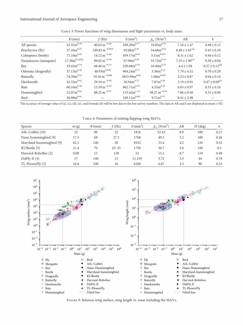
Table 3: Power functions of wing dimensions and flight parameters vs. body mass.
R (mm) f (Hz) S (mm2) pw (N/m2) AR k
All species 43.31m0.39 40.63m−0.29 430.29m0.77 10.85m0.25 7.16± 1.47 0.48± 0.13Brachycera (fly) 27.16m0.27 140.83m−0.054 93.06m0.39 54.68m0.62 8.48± 2.81(a) 0.45± 0.10Coleoptera (beetle) 71.10m0.43 14.12m−0.48 459.17m0.61 3.31m0.037 8.31± 1.62 0.44± 0.12Nematocera (mosquito) 17.38m0.14(b) 99.02m−0.30 97.90m0.39 33.72m0.41 7.35± 1.90(c) 0.39± 0.04Bee 19.41m0.14 48.46m−0.13 230.68m0.33 10.40m0.75 4.4± 1.94 0.37± 0.12(d)
Odonata (dragonfly) 57.13m0.36 40.93m0.036 964.24m0.71 3.56m0.23 7.79± 4.52 0.70± 0.29Butterfly 74.39m0.53 19.16m−0.090 3825.99m0.83 1.60m0.095 2.23± 0.87 0.64± 0.14Hawkmoth 42.32m0.42 29.34m−0.20 56.94m5.71 7.07m0.20 5.19± 0.91 0.47± 0.09(e)
Bats 60.16m0.36 15.59m−0.19 862.71m0.76 4.55m0.29 6.65± 0.97 0.53± 0.10Hummingbird 21.07m0.62 88.25m−0.57 133.42m1.15 38.27m−0.16 7.86± 0.56 0.31± 0.04Bird 36.98m0.41 — 349.11m0.80 9.71m0.27 8.41± 2.98 —
The accuracy of average value of (a), (c), (d), (e), and formula (b) will be low due to the less survey numbers. The data in AR and k are displayed asmean ± SD.
Table 4: Parameters of existing flapping wing MAVs.
Species m (g) R (mm) f (Hz) S (mm2) pw (N/m2) AR ∅ (deg) k
ASL-Colibri [10] 22 90 22 1816 52.43 8.9 180 0.21
Nano hummingbird [8] 17.5 68 27.5 1768 49.5 5.2 180 0.26
Maryland hummingbird [9] 62.1 140 20 9232 33.4 4.2 120 0.52
KUBeetle [3] 21.4 70 25–35 1750 50.7 5.6 190 0.3
Harvard-RoboBee [2] 0.08 15 120 52 15.1 8.7 110 0.49
DelFly II [4] 17 140 13 11,195 3.72 3.5 44 0.78
TL-FlowerFly [5] 16.6 100 10 6100 6.67 3.3 90 0.33
FlyMosquitoBee
Bird
BeetleDragonflyButterflyHawkmothsBatsHummingbird
ASL-ColibriNano-HummingbirdMaryland-hummingbirdKUBeetleHarvard-RobobeeDelFly IITL-FlowerFlyFitted line
10−4 10−3 10−2 10−1 100 101 102 103 104 105 106
Mass (g)
Win
g su
rface
(mm
2 )
10−3
10−2
10−1
100
101
102
103
104
105
106
107
FlyMosquitoBee
Bird
BeetleDragonflyButterflyHawkmothsBatsHummingbird
ASL-ColibriNano-HummingbirdMaryland-hummingbirdKUBeetleHarvard-RobobeeDelFly IITL-FlowerFlyFitted line
10−4 10−3 10−2 10−1 100 101 102 103 104 105
Mass (g)
Win
g le
ngth
(mm
)
10−3
10−2
10−1
100
101
102
103
104
Figure 9: Relation wing surface, wing length vs. mass including the MAVs.
17International Journal of Aerospace Engineering

ASL-Colibri, KUBeetle, and Nano Hummingbird are similarand larger than others, which means more lift can be pro-duced per square meter. By contrast, the wing loading ofHarvard-RoboBee is lower in the twin-wing flapping wingMAVs; thus, it means that it might cost more energy perunit force. Also, in X-wing flapping wing MAVs, the wingperformance of TL-FlowerFly seems better than that ofDelFly-II. In Figure 11 (right), the pw −AR ratio inHarvard-RoboBee is less than others, which reveals that itmay not have an excellent wing performance. Also, it mightbe associated with the flexibility of the wing. RegardingMaryland-Hummingbird, the good performance is exhib-ited, although its wing loading is small.
The lift generation is linked not only to the wing perfor-mance, such as wing surface, frequency, and wing length, butalso to other properties, such as wing materials, the positionof a stiffener, flexural stiffness, and wingtip shape. Forinstance, a rounded wing for a given span generates an ellip-tic transverse lift distribution, which contributes to a mini-mum induced drag and a constant lift coefficient along thewingspan. And the tapered aft-swept tips produce less dragfor a given lift and extract more energy from the vertical wake[51]. According to the study of Shyy et al. [52], overly flexiblewings will result in inefficient aerodynamic performance. Thelift is also affected by the wing fabrication process. Currently,many category wing shapes are designed using differentmaterials, such as Nylon, Latex, PVC film, and Mylar. Athummingbird scale, many wings, such as those of Nanohummingbird [53] and ASL-Colibri [20], are made usingthe traditional simple method of cut-and-edge because it issimple and easily repeatable. In Nan et al.’s study [20], wings
of ASL-Colibri are made of Mylar membrane (15 μm) andCFRP stiffeners (width = 1mm; thickness = 0 12mm) andare thus subjected to deformation when flapping. The princi-pal steps of wing production shown in Figure 12 are similarto that of Nano hummingbird [53]. According to the flightdemonstration of ASL-Colibri shown in Figure 13, thedesigned wing based on scale law in this paper is reasonable,and the lift test results are precise and repeatable (see detailsin [20]), thereby enabling a 17.2 g ASL-Colibri vehicle to fly.
At insect scale, the microelectromechanical systems(MEMS) are employed to construct wing design becausethese systems improve the quality of accuracy and repeatabil-ity, for example, in the case of the Harvard-RoboBee [54] andthe KUBeetle [55]. Impliedly, to reduce the vehicle size, theminiaturization should be overcome since the traditionalmethod does not offer adequate precision and repeatability[56]. Some wings are manufactured by CNC machines, suchas DelFly II [4] and wings designed by Chang et al. [57].Additional details of wing designs based on different mate-rials and methods are summarized in Table 5.
4. Conclusions and Future Works
In this paper, the geometric similarity is first studied. Thepw −AR ratio is then defined to estimate wing performanceand aerodynamic performance. After that, the comprehen-sive scale laws are studied and achieved for natural flyers.Besides, the lumped parameter is first comprehensively stud-ied. It is observed that the relationship between the aspectratio and the lumped parameter is inversely proportion andthe lumped parameter is independent to the body massthrough geometric similarity analysis. Via statistical studyamong natural flyers, the lumped parameters are nearly con-stant from the body mass. The power functions of wingdimensions and flight parameters against the body mass arealso summarized. These functions might vary on the numberof natural flyers surveyed, but the achieved relationshipsindicate the universal tendencies, and it is verified that theperformance of artificial wings in flapping wingMAVs followthese scaled rules. Therefore, the obtained scale laws areacceptable. Last, the wing manufacture of ASL-Colibri isinteroperated as an example, and take-off demonstration ofASL-Colibri is also performed, which indicates that thedesigned wings based on the obtained scale law in this paperare acceptable. Moreover, artificial wings, including fabrica-tion materials and methods, are summarized. Summarily,the current study will provide a useful dataset as a referencefor future research. These results provide a simple but pow-erful guideline for biologists and engineers who are studyingthe morphology of natural flyers and designing flappingwing MAVs.
In our future work, we will focus on (1) the optimaldesign and advanced simulation on the flapping wing MAVvia computational intelligence-assisted design (CIAD) [58]and (2) improvement of the MAV design by developingreliability indices for capturing the time-varying andnonlinear dynamical performance during experimentalstudies; (3) furthermore, we will look at the intelligent
FlyMosquitoBeeBeetleDragonflyButterflyHawkmothsBats
HummingbirdASL-ColibriNano-HummingbirdMaryland-HummingbirdKUBeetleHarvard-RobobeeDelFly IITL-FlowerFly
Aspect ratio100 101
Lum
ped
para
met
er
10−3
10−2
10−1
100
101
Figure 10: Relation lumped parameter vs. aspect ratio including theflapping wing MAVs.
18 International Journal of Aerospace Engineering

0
20
40
60
80Av
erag
e
Flapping wing MAVs
ASL
-Col
ibri
Nan
o-H
umm
ingb
ird
Mar
ylan
-Hum
min
gbird
KUBe
etle
Har
vard
-Rob
obee
Delfl
y-II
TL-F
low
erfly
Wing loadingAspect ratio
X-wingTwin-wing
ASL
-Col
ibri
Nan
o-H
umm
ingb
ird
Mar
ylan
-Hum
min
gbird
KUBe
etle
Har
vard
-Rob
obee
Delfl
y-II
TL-F
low
erfly
0
5
10
15
Twin-wing
Pw-A
R ra
tioFlapping wing MAVs
Pw-AR ratio
X-wing
Figure 11: Wing loading and aspect ratio for flapping wing MAVs (left) and pw −AR ratio (right).
Wing trailing edge
(1) (2)
(5)
Wing leading edge
Win
g roo
t edg
e
Win
g tip
edge
(a)
(3)
(4)
(b)
Camber angleStiffener position
angle
InnerCRCT
R
Outer
(c) (d)
Figure 12: Principal steps of wing production and certain selected wings. (a)–(b): (1) mylar foil is taped on top of a printed template withdesired wing geometry. (2) The contours of future wing sleeves are cut out. (3) Strips of Teflon are placed at the position of wing bars andfixed. Glue (Pattex contact glue diluted 1:1 with acetone) is applied, and the sleeves are completed by folding the foil around the Teflonstrips. (4) Glue is applied at the position of stiffeners and the stiffeners are glued. (5) The rest of the wing is cut out, and the Teflon stripsare removed. (c) Wing geometry: CT wing tip chord and CR wing root chord. (d) Certain selected wings [20].
19International Journal of Aerospace Engineering

control for the autonomous MAV using artificial intelligencealgorithms via CIAD.
Nomenclature
A: Total surface, m2
AR: Aspect ratioc: Mean wing chord, mm
CL: Lift coefficientCL: Mean lift coefficientf : Wingbeat frequency, HzFL: Mean lift force, Ng: Gravitational acceleration, m/s2
k: Wing lumped parameterl: Characteristic length, mm: Flyer mass, g
(a)
t = 0 s 3 s2 s1 s
(b)
Figure 13: Take-off demonstration with sail-like damper for passive stability: photo of the prototype vehicle used in the test (a) and take-offsequence (b). The full video recording is available online: https://youtu.be/oaFR815dtIo [20].
Table 5: Artificial wings, including fabrication materials and methods.
Authors ModelWing
model (cm)Fabricationmethod
MaterialsVeins Membrane
Bontemps et al. [95] — MEMS-based SU-8 Parylene
Roll et al. [96] — Cut-and-glue Carbon fiber Mylar
Watman andFurukawa [97]
— — Carbon pultrusions Mylar
Sahai et al. [98] — SCMTitanium alloy with carbon
fiber reinforcementUltra polyester film
Kim et al. [99] — Cut-and-glue Graphite/epoxy composite Flexible PVC
Campolo [100] DipteranChemical vapor
deposition and moldingCarbon fiber Cellulose acetate film
Wood [101] Dipteran SCM Carbon fiber Mylar
Nguyen et al. [102] InsectsCut-and-glue with
paper moldCarbon rods Mylar
Lentink et al. [103] DragonflyCut-and-glue with
paper moldCarbon rods Mylar
Meng et al. [104] Hoverfly Syrphidae MEMS-based SU-8 Polyimide
Tanaka and wood [105] Hovering Eristalis Micro molding Thermosetting resin —
Ma et al. [106] Hovering Eristalis SCM Carbon fiber Mylar
Pornisin-Siriak et al. [107] Bat MEMS-basedTitanium alloy with carbon
fiber reinforcementParylene
Ho et al. [50] Cicada MEMS-basedTitanium alloy with carbon
fiber reinforcementParylene
Keennon et al. [8] Hummingbird — Carbon fiber —
Tanaka et al. [108] Hummingbird — Carbon fiber-reinforced plastic Parylene
Coleman et al. [9] Hummingbird Mold-glue Carbon fiber1/32 foammembrane
Nan et al. [20] Hummingbird Cut-and-glue Carbon fiber Mylar
20 International Journal of Aerospace Engineering

pw: Wing loading, N/m2
pw −AR ratio: The ratio of wing loading to aspect ratioR: Single wing length, mmS: Single wing surface, mm2
UCP: Average velocity at pressure centre, m/sV : Volume, m3
Vt : Forward flight velocity, m/sW: Weight, Nρ: Air density, kg/m3
ϕ: Flapping amplitude angle, deg.
Data Availability
The data used to support the findings of this study areavailable from the corresponding author upon request.
Conflicts of Interest
The authors declare that they have no conflicts of interest.
Acknowledgments
The authors would like to acknowledge the partial supportsprovided by the National Natural Science Foundation ofChina (No. 51575090), the Artigent Young Talent Scholar-ship Award, and the Dean’s Scholarships for InternationalAcademic Excellence, School of Engineering and Built Envi-ronment, Glasgow Caledonian University.
References
[1] X. Deng, L. Schenato, W. C. Wu, and S. S. Sastry, “Flappingflight for biomimetic robotic insects: part I-system model-ing,” IEEE Transactions on Robotics, vol. 22, no. 4, pp. 776–788, 2006.
[2] R. J. Wood, “The first takeoff of a biologically-inspired at-scale robotic insect,” IEEE Transactions on Robotics, vol. 24,no. 2, pp. 341–347, 2008.
[3] H. V. Phan, T. Kang, and H. C. Park, “Design and stable flightof a 21 g insect-like tailless flapping wing micro air vehiclewith angular rates feedback control,” Bioinspiration & Biomi-metics, vol. 12, no. 3, 2017.
[4] B. Bruggeman, Improving Flight Performance of DelFly II inHover by Improving Wing Design and Driving Mechanism,Delft University of Technology M. Sc. thesis, 2010.
[5] Q. V. Nguygen, W. L. Chan, and M. Debiasi, “Performancetests of a hovering flapping wing micro air vehicle with dou-ble wing clap-and-fling mechanism,” in International MicroAir Vehicles Conference and Flight Competition, pp. 1–8,Aachen, Germany, 2015.
[6] Festo Corporate, “Dragonfly,” Festo Report, 2013.[7] Festo Corporate, “Butterfly,” Festo Report, 2015.[8] M. Keennon, K. Klingebiel, and H. Won, “Development of
the nano hummingbird: a tailless flapping wing micro airvehicle,” in 50th AIAA Aerospace Sciences Meeting includingthe New Horizons Forum and Aerospace Exposition, Nash-ville, Tennessee, January 2012.
[9] D. Coleman, M. Benedict, V. Hrishikeshavan, and I. Chopra,“Design, development and flight-testing of a robotic hum-mingbird,” in AHS 71st annual Forum, pp. 1–18, VirginiaBeach, Virgina, 2015.
[10] A. Roshanbin, H. Altartouri, M. Karásek, and A. Preumont,“Colibri: a hovering flapping twin-wing robot,” InternationalJournal of Micro Air Vehicles, vol. 9, no. 4, pp. 270–282, 2017.
[11] Festo Corporate, “Smartbird,” Festo Report, 2011.[12] A. P. Willmott and C. P. Ellington, “The mechanics of flight
in the hawkmoth Manduca sexta. I. kinematics of hoveringand forward flight,” Journal of Experimental Biology,vol. 200, Part 21, pp. 2705–2722, 1997.
[13] S. A. Ansari, K. Knowles, and R. Zbikowski, “Insectlike flap-ping wings in the hover part II: effect of wing geometry,”Journal of Aircraft, vol. 45, no. 6, pp. 1976–1990, 2008.
[14] N. Phillips, K. Knowles, and R. J. Bomphrey, “The effect ofaspect ratio on the leading-edge vortex over an insect-likeflapping wing,” Bioinspiration & Biomimetics, vol. 10, no. 5,2015.
[15] K. B. Lua, Y. J. Lee, T. T. Lim, and K. S. Yeo, “Aerodynamiceffects of elevating motion on hovering rigid hawkmothlikewings,” AIAA Journal, vol. 54, no. 8, pp. 2247–2264, 2016.
[16] A. Pelletier and T. J. Mueller, “Low Reynolds number aerody-namics of low-aspect-ratio, thin/flat/cambered-plate wings,”Journal of Aircraft, vol. 37, no. 5, pp. 825–832, 2000.
[17] S. Deng, M. Percin, and B. van Oudheusden, “Experimentalinvestigation of aerodynamics of flapping-wing micro-air-vehicle by force and flow-field measurements,”AIAA Journal,vol. 54, no. 2, pp. 588–602, 2016.
[18] Q. Wang, J. F. L. Goosen, and F. van Keulen, “An efficientfluid-structure interaction model for optimizing twistableflapping wings,” Journal of Fluids and Structures, vol. 73,pp. 82–99, 2017.
[19] K. Mazaheri and A. Ebrahimi, “Experimental investigationof the effect of chordwise flexibility on the aerodynamicsof flapping wings in hovering flight,” Journal of Fluids andStructures, vol. 26, no. 4, pp. 544–558, 2010.
[20] Y. Nan, M. Karásek, M. E. Lalami, and A. Preumont, “Exper-imental optimization of wing shape for a hummingbird-likeflapping wing micro air vehicle,” Bioinspiration & Biomimet-ics, vol. 12, no. 2, p. 026010, 2017.
[21] W. Shyy, H. Aono, S. K. Chimakurthi et al., “Recent progressin flapping wing aerodynamics and aeroelasticity,” Progressin Aerospace Science, vol. 46, no. 7, pp. 284–327, 2010.
[22] Y. Nan, M. Karasek, M. Lalami, and H. Altartouri, “An exper-imental study on effect of wing geometry of hummingbird-like flapping wing in the hover,” in International Micro AirVehicles Conference and Flight Competition, Aachen, Ger-many, 2015.
[23] Y. J. Lee, K. B. Lua, and T. T. Lim, “Aspect ratio effects onrevolving wings with rossby number consideration,” Bioin-spiration & Biomimetics, vol. 11, no. 5, 2016.
[24] Y. J. Lee, K. B. Lua, T. T. Lim, and K. S. Yeo, “A quasi-steadyaerodynamic model for flapping flight with improved adapt-ability,” Bioinspiration & Biomimetics, vol. 11, no. 3, 2016.
[25] Y. J. Lee and K. B. Lua, “Optimization of simple and complexpitching motions for flapping wings in hover,” AIAA Journal,vol. 56, no. 6, pp. 2466–2470, 2018.
[26] A. Azuma, The Biokinetics of Flying and Swimming, Springer-Verlag, Tokyo, 1992.
[27] R. F. Chapman, The Insects: Structure & Function, CambridgeUniversity Press, 1998.
[28] M. J. Lighthill, “Introduction to the Scaling of Aerial Locomo-tion,” in Scale Effects in Animals Locomotion, pp. 365–404,Academic Press, London, 1977.
21International Journal of Aerospace Engineering

[29] R. Dudley, “Biomechanics of flight in neotropical butterflies:morphometrics and kinematics,” Journal of ExperimentalBiology, vol. 150, pp. 37–53, 1990.
[30] D. N. Byrne, S. L. Buchmann, and H. G. Spangler, “Relation-ship between wing loading, wing beat frequency and bodymass in homopterous insects,” Journal of Experimental Biol-ogy, vol. 135, pp. 9–23, 1988.
[31] H. C. Corben, “Wing-beat frequencies, wing-areas andmasses of flying insects and hummingbirds,” Journal of The-oretical Biology, vol. 102, no. 4, pp. 611–623, 1983.
[32] R. D. Bullen and N. L. McKenzie, “Scaling bat wingbeat fre-quency and amplitude,” Journal of Experimental Biology,vol. 205, Part 17, pp. 2615–2626, 2002.
[33] N. S. Ha, Q. T. Truong, N. S. Goo, and H. C. Park, “Relation-ship between wingbeat frequency and resonant frequencyof the wing in insects,” Bioinspiration & Biomimetics, vol. 8,no. 4, 2013.
[34] C. H. Greenewalt, Hummingbirds, Dover Publications, 1990.[35] H. Tennekes, The Simple Science of Flight (from Insects to
Jumbo Jets), MIT Press, Boston, MA, 1996.[36] W. Shyy, M. Berg, and D. Ljungqvist, “Flapping and flexible
wings for biological and micro air vehicles,” Progress in Aero-space Science, vol. 35, no. 5, pp. 455–505, 1999.
[37] R. A. Norberg and U. M. Norberg, “Take-off, landing, andflight speed during fishing flights of Gavia stellata (Pont.),”Ornis Scandinavica, vol. 2, no. 1, p. 55, 1971.
[38] R. Dudley, The Biomechanics of Insect Flight: Form, Function,Evolution, Princeton University Press, 2002.
[39] U. M. Norberg, “Energetics of flight,” in Avian Energetics andNutritional Ecology, C. Carey, Ed., pp. 199–249, Springer,Boston, MA, USA, 1996.
[40] U. M. Norberg and R. Å. Norberg, “Ecomorphology of flightand tree-trunk climbing in birds,” in Acta XIX CongressusInternationalis Ornithological, vol. 2, pp. 2271–2282, Ottawa,Canada, 1988.
[41] U. M. Lindhe Norberg, “Structure, form, and function offlight in engineering and the living world,” Journal ofMorphology, vol. 252, no. 1, pp. 52–81, 2002.
[42] H. Oehme, “On the aerodynamics of separated primariesin the avian wing,” in Scale Effects in Animal Locomotion,T. J. Pedley, Ed., pp. 479–494, Academic Press, London,New York, 1977.
[43] U. M. Lindhe Norberg, “Flight and scaling of flyers innature,” in Flow Phenomena in Nature Volume 1: A Challengeto Engineering Design, WIT Transactions on State of the Artin Science and Engineering, pp. 120–154, 2006.
[44] M. H. Dickinson, F. O. Lehmann, and S. P. Sane, “Wing rota-tion and the aerodynamic basis of insect flight,” Science,vol. 284, no. 5422, pp. 1954–1960, 1999.
[45] C. P. Ellington, “The aerodynamics of hovering insect flight.II. Morphological parameters,” Philosophical Transactionsof the Royal Society B: Biological Sciences, vol. 305, no. 1122,pp. 17–40, 1984.
[46] K. B. Lua, T. T. Lim, and K. S. Yeo, “Scaling of aerodynamicforces of three-dimensional flapping wings,” AIAA Journal,vol. 52, no. 5, pp. 1095–1101, 2014.
[47] C. H. Greenewalt, Dimensional Relationships for FlyingAnimals, vol. 144, Smithsonian Miscellaneous Collections,1962.
[48] U. M. Norberg, Vertebrate Flight: Mechanics, Physiology,Morphology, Ecology and Evolution, Springer, 1990.
[49] C. Pennycuick, “Wingbeat frequency of birds in steadycruising flight: new data and improved predictions,”Journal of Experimental Biology, vol. 199, Part 7,pp. 1613–1618, 1996.
[50] S. Ho, H. Nassef, N. Pornsinsirirak, Y. C. Tai, and C. M. Ho,“Unsteady aerodynamics and flow control for flapping wingflyers,” Progress in Aerospace Science, vol. 39, no. 8,pp. 635–681, 2003.
[51] C. P. van Dam, K. Nikfetrat, and P. M. H.W. Vijgen, “Lift anddrag calculations for wings and tails: techniques and applica-tions,” Contemporary Mathematics, vol. 141, pp. 463–477,1993.
[52] W. Shyy, H. Aono, C. K. Kang, and H. Liu, An Introduction toFlapping Wing Aerodynamics, Cambridge University Press,New York, NY, 2013.
[53] M. T. Keennon, K. R. Klingebiel, A. Andryukov, and B. D.Hibbs, Air Vehicle Flight Mechanism and Control Method,Aerovironment Patent, 2010.
[54] J. K. Shang, S. A. Combes, B. M. Finio, and R. J. Wood, “Arti-ficial insect wings of diverse morphology for flapping-wingmicro air vehicles,” Bioinspiration & Biomimetics, vol. 4,no. 3, 2009.
[55] N. S. Ha, Q. V. Nguyen, N. S. Goo, and H. C. Park, “Static anddynamic characteristics of an artificial wing mimicking anAllomyrina dichotoma beetle’s hind wing for flapping-wingmicro air vehicles,” Experimental Mechanics, vol. 52, no. 9,pp. 1535–1549, 2012.
[56] W. Shyy, C. K. Kang, P. Chirarattananon, S. Ravi, and H. Liu,“Aerodynamics, sensing and control of insect-scale flapping-wing flight,” Proceedings of the Royal Society A: Mathemati-cal, Physical and Engineering Science, vol. 472, no. 2186, arti-cle 20150712, 2016.
[57] K. Chang, A. Chaudhuri, J. Rue et al., “Improving the fabrica-tion process of micro-air-vehicle flapping wings,” AIAA Jour-nal, vol. 53, no. 10, pp. 3039–3048, 2015.
[58] Y. Chen and Y. Li, Computational Intelligence AssistedDesign: In Industrial Revolution 4.0, CRC Press, Boca Raton,1st Edition edition, 2018.
[59] Y. P. Liu and M. Sun, “Wing kinematics measurement andaerodynamic force and moments computation of hoveringhoverfly,” in 2007 1st International Conference on Bioinfor-matics and Biomedical Engineering, pp. 452–455, Wuhan,China, July 2007.
[60] S. Mao and D. Gang, “Lift and power requirements of hover-ing insect flight,” Acta Mechanica Sinica, vol. 19, no. 5,pp. 458–469, 2003.
[61] S. N. Fry, R. Sayaman, and M. H. Dickinson, “The aerody-namics of hovering flight in Drosophila,” Journal of Experi-mental Biology, vol. 208, no. 12, pp. 2303–2318, 2005.
[62] A. R. Ennos, “The kinematics and aerodynamics of the freeflight of some Diptera,” Journal of Experimental Biology,vol. 142, pp. 49–85, 1989.
[63] O. Sotavalta, “The essential factor regulating the wing-strokefrequency of insects in wing mutilation and loading exper-iments at subatmospheric pressure,” Annales ZoologiciSocietatis Zoologicae Botanicae Fennicae Vanamo, vol. 15,pp. 1–67, 1952.
[64] L. Ristroph, G. Ristroph, S. Morozova et al., “Active andpassive stabilization of body pitch in insect flight,” Journalof The Royal Society Interface, vol. 10, no. 85, article20130237, 2013.
22 International Journal of Aerospace Engineering

[65] B. Hocking, “The intrinsic range and flight speed of insects,”Transactions of the Royal Entomological Society of London,vol. 104, pp. 223–345, 1953.
[66] R. Dudley, “Extraordinary flight performance of orchid bees(Apidae: Euglossini) hovering in heliox (80% He/20% O2),”Journal of Experimental Biology, vol. 198, Part 4, pp. 1065–1070, 1995.
[67] C. P. Ellington, “The aerodynamics of hovering insectflight. III. Kinematics,” Philosophical Transactions of theRoyal Society B: Biological Sciences, vol. 305, no. 1122,pp. 41–78, 1984.
[68] R. Dudley and C. P. Ellington, “Mechanics of forward flight inbumblebees: I. Kinematics and morphology,” Journal ofExperimental Biology, vol. 148, pp. 19–52, 1990.
[69] M. Okamoto, K. Yasuda, and A. Azuma, “Aerodynamic char-acteristics of the wings and body of a dragonfly,” Journal ofExperimental Biology, vol. 199, Part 2, pp. 281–294, 1996.
[70] M. Sato and A. Azuma, “The flight performance of a damsel-fly Ceriagrion melanurum Selys,” Journal of ExperimentalBiology, vol. 200, Part 12, pp. 1765–1779, 1997.
[71] R. Åke Norberg, “The pterostigma of insect wings an inertialregulator of wing pitch,” Journal of Comparative Physiology,vol. 81, no. 1, pp. 9–22, 1972.
[72] O. Sotavalta, “The effect of wing inertia on the wing-strokefrequency of moths, dragonflies and cockroach,” AnnalesBotanici Fennici, vol. 20, pp. 93–101, 1954.
[73] A. Magnan, “La locomotion chez les animaux 1,” Le vol desinsectes, Hermann, Paris, 1934.
[74] B. Cheng, X. Deng, and T. L. Hedrick, “The mechanics andcontrol of pitching manoeuvres in a freely flying hawkmoth(Manduca sexta),” The Journal of Experimental Biology,vol. 214, no. 24, pp. 4092–4106, 2011.
[75] A. P. Willmott and C. P. Ellington, “The mechanics of flightin the hawkmoth Manduca sexta. II. Aerodynamic conse-quences of kinematic and morphological variation,” Journalof Experimental Biology, vol. 200, Part 21, pp. 2723–2745,1997.
[76] F. T. Muijres, L. C. Johansson, M. S. Bowlin, Y. Winter, andA. Hedenström, “Comparing aerodynamic efficiency in birdsand bats suggests better flight performance in birds,” PLoSOne, vol. 7, no. 5, 2012.
[77] A. Hedenstrom, L. C. Johansson, M. Wolf, R. von Busse,Y. Winter, and G. R. Spedding, “Bat flight generates complexaerodynamic tracks,” Science, vol. 316, no. 5826, pp. 894–897,2007.
[78] F. T. Muijres, L. C. Johansson, R. Barfield, M. Wolf, G. R.Spedding, and A. Hedenstrom, “Leading-edge vorteximproves lift in slow-flying bats,” Science, vol. 319, no. 5867,pp. 1250–1253, 2008.
[79] F. T. Muijres, L. Christoffer Johansson, Y. Winter, andA. Hedenström, “Leading edge vortices in lesser long-nosedbats occurring at slow but not fast flight speeds,” Bioinspira-tion & Biomimetics, vol. 9, no. 2, article 025006, 2014.
[80] R. Bullen and N. L. McKenzie, “Bat airframe design: flightperformance, stability and control in relation to foragingecology,” Australian Journal of Zoology, vol. 49, no. 3,pp. 235–261, 2001.
[81] N. L. McKenzie, L. Fontanini, N. V. Lindus, and M. R. Wil-liams, “Biological inventory of Koolan Island, Western Aus-tralia 2. Zoological notes,” Records-Western AustralianMuseum, vol. 17, pp. 249–266, 1995.
[82] J. H. Fullard, C. Koehler, A. Surlykke, and N. L. McKenzie,“Echolocation ecology and flightmorphology of insectivorousbats (Chiroptera) in South-Western Australia,” AustralianJournal of Zoology, vol. 39, no. 4, pp. 427–438, 1991.
[83] N. L. McKenzie and J. K. Rolfe, “Structure of bat guilds in theKimberley mangroves, Australia,” Journal of Animal Ecology,vol. 55, no. 2, pp. 401–420, 1986.
[84] M. Thollesson and U. M. Norberg, “Moments of inertia of batwings and body,” Journal of Experimental Biology, vol. 158,pp. 19–35, 1991.
[85] M. J. Fernandez, Flight Performance and ComparativeEnergetics of the Giant Andean Hummingbird, PhD Thesis,University of California, Berkeley, 2010.
[86] P. Chai and D. Millard, “Flight and size constraints: hoveringperformance of large hummingbirds under maximal load-ing,” Journal of Experimental Biology, vol. 200, Part 21,pp. 2757–2763, 1997.
[87] B. W. Tobalske, D. L. Altshuler, and D. R. Powers, “Take-offmechanics in hummingbirds (Trochilidae),” Journal ofExperimental Biology, vol. 207, no. 8, pp. 1345–1352, 2004.
[88] D. J. Wells, “Muscle performance in hovering humming-birds,” Journal of Experimental Biology, vol. 178, pp. 39–57,1993.
[89] M. Wolf, V. M. Ortega-Jimenez, and R. Dudley, “Structure ofthe vortex wake in hovering Anna’s hummingbirds (Calypteanna),” Proceedings of the Royal Society B: Biological Sciences,vol. 280, no. 1773, article 20132391, 2013.
[90] D. Evangelista, M. J. Fernández, M. S. Berns, A. Hoover, andR. Dudley, “Hovering energetics and thermal balance inAnna’s hummingbirds (Calypte anna),” Physiological andBiochemical Zoology, vol. 83, no. 3, pp. 406–413, 2010.
[91] P. Chai, R. Harrykissoon, and R. Dudley, “Hummingbirdhovering performance in hyperoxic heliox: effects of bodymass and sex,” Journal of Experimental Biology, vol. 199, Part12, pp. 2745–2755, 1996.
[92] T. Weis-Fogh, “Energetics of hovering flight in humming-birds and in Drosophila,” Journal of Experimental Biology,vol. 56, pp. 79–104, 1972.
[93] D. L. Altshuler, Ecophysiology of Hummingbird Flight alongElevational Gradients: an Integrated Approach, PhD Thesis,University Of Texas at Austin, 2001.
[94] S. Dhawan, “Bird flight,” Sadhana, vol. 16, no. 4, pp. 275–352,1991.
[95] A. Bontemps, T. Vanneste, J. B. Paquet, T. Dietsch,S. Grondel, and E. Cattan, “Design and performance of aninsect-inspired nano air vehicle,” Smart Materials and Struc-tures, vol. 22, no. 1, 2013.
[96] J. A. Roll, B. Cheng, and X. Deng, “Design, fabrication, andexperiments of an electromagnetic actuator for flapping wingmicro air vehicles,” in 2013 IEEE International Conference onRobotics and Automation, pp. 809–815, Karlsruhe, Germany,May 2013.
[97] D. Watman and T. Furukawa, “A parametric study of flap-ping wing performance using a robotic flapping wing,” in2009 IEEE International Conference on Robotics and Automa-tion, pp. 3638–3643, Kobe, Japan, May 2009.
[98] R. Sahai, K. C. Galloway, and R. J. Wood, “Elastic elementintegration for improved flapping-wing micro air vehicleperformance,” IEEE Transactions on Robotics, vol. 29, no. 1,pp. 32–41, 2013.
23International Journal of Aerospace Engineering

[99] D.-K. Kim, H.-I. Kim, J.-H. Han, and K.-J. Kwon, “Experi-mental investigation on the aerodynamic characteristics of abio-mimetic flapping wing with macro-fiber composites,”Journal of Intelligent Material Systems and Structures,vol. 19, no. 3, pp. 423–431, 2007.
[100] D. Campolo, M. Azhar, G. K. Lau, and M. Sitti, “Can DCmotors directly drive flapping wings at high frequency andlarge wing strokes?,” IEEE/ASME Transactions on Mechatro-nics, vol. 19, no. 1, pp. 109–120, 2014.
[101] R. J. Wood, “Design, fabrication, and analysis of a 3DOF,3cm flapping-wing MAV,” in 2007 IEEE/RSJ InternationalConference on Intelligent Robots and Systems, pp. 1576–1581, San Diego, CA, USA, October-November 2007.
[102] Q.-V. Nguyen, W. L. Chan, and M. Debiasi, “An insect-inspired flapping wing micro air vehicle with double wingclap-fling effects and capability of sustained hovering,” in ,Article ID 94290USPIE Smart Structures and Materials Non-destructive Evaluation and Health Monitoring, vol. 9429, SanDiego, CA, USA, March 2015.
[103] D. Lentink, S. R. Jongerius, and N. L. Bradshaw, “The scalabledesign of flapping micro-air vehicles inspired by insect flight-Flying Insects and Robots, D. Floreano, J. C. Zufferey, M.Srinivasan, and C. Ellington, Eds., pp. 185–205, Springer,Berlin, Heidelberg, 2009.
[104] K. Meng, W. Zhang, W. Chen et al., “The design and micro-machining of an electromagnetic MEMS flapping-wingmicro air vehicle,” Microsystem Technologies, vol. 18, no. 1,pp. 127–136, 2012.
[105] H. Tanaka and R. J. Wood, “Fabrication of corrugated artifi-cial insect wings using laser micromachined molds,” Journalof Micromechanics and Microengineering, vol. 20, no. 7, 2010.
[106] K. Y. Ma, P. Chirarattananon, S. B. Fuller, and R. J. Wood,“Controlled flight of a biologically inspired, insect-scalerobot,” Science, vol. 340, no. 6132, pp. 603–607, 2013.
[107] T. N. Pornsin-Sirirak, Y.-C. Tai, C.-M. Ho, and M. Keennon,“Microbat: a palm-sized electrically powered ornithopter,” inProceedings of NASA/JPL Workshop on Biomorphic Robotics,pp. 14–17, Pasadena, CA, USA, August 2001.
[108] H. Tanaka, H. Okada, Y. Shimasue, and H. Liu, “Flexible flap-ping wings with self-organized microwrinkles,” Bioinspira-tion & Biomimetics, vol. 10, no. 4, 2015.
24 International Journal of Aerospace Engineering

International Journal of
AerospaceEngineeringHindawiwww.hindawi.com Volume 2018
RoboticsJournal of
Hindawiwww.hindawi.com Volume 2018
Hindawiwww.hindawi.com Volume 2018
Active and Passive Electronic Components
VLSI Design
Hindawiwww.hindawi.com Volume 2018
Hindawiwww.hindawi.com Volume 2018
Shock and Vibration
Hindawiwww.hindawi.com Volume 2018
Civil EngineeringAdvances in
Acoustics and VibrationAdvances in
Hindawiwww.hindawi.com Volume 2018
Hindawiwww.hindawi.com Volume 2018
Electrical and Computer Engineering
Journal of
Advances inOptoElectronics
Hindawiwww.hindawi.com
Volume 2018
Hindawi Publishing Corporation http://www.hindawi.com Volume 2013Hindawiwww.hindawi.com
The Scientific World Journal
Volume 2018
Control Scienceand Engineering
Journal of
Hindawiwww.hindawi.com Volume 2018
Hindawiwww.hindawi.com
Journal ofEngineeringVolume 2018
SensorsJournal of
Hindawiwww.hindawi.com Volume 2018
International Journal of
RotatingMachinery
Hindawiwww.hindawi.com Volume 2018
Modelling &Simulationin EngineeringHindawiwww.hindawi.com Volume 2018
Hindawiwww.hindawi.com Volume 2018
Chemical EngineeringInternational Journal of Antennas and
Propagation
International Journal of
Hindawiwww.hindawi.com Volume 2018
Hindawiwww.hindawi.com Volume 2018
Navigation and Observation
International Journal of
Hindawi
www.hindawi.com Volume 2018
Advances in
Multimedia
Submit your manuscripts atwww.hindawi.com


![Experimental analysis of submerged flapping foils ... · principles of flapping foil wave propulsion [1,2,3,4]. MOST (Autonomous Vessels) Ltd have developed a long range endurance](https://img.pdfslide.us/doc/110x75/5f061c6a7e708231d4165844/experimental-analysis-of-submerged-iapping-foils-principles-of-iapping-foil.jpg)
![Evolution of flight in animals · 2 Evolution of insect flight Several theories have been suggested for the origin of flight in insects (summarized in Thomas and Norberg [1])](https://img.pdfslide.us/doc/110x75/5f0850067e708231d4216393/evolution-of-iight-in-animals-2-evolution-of-insect-iight-several-theories-have.jpg)