Embed Size (px)
Citation preview
www.canalplast.it - [email protected]
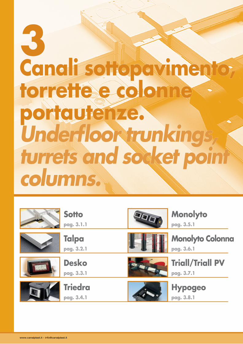
3Canali sottopavimento, torrette e colonne portautenze.Underfloor trunkings, turrets and socket point columns.
Sotto pag. 3.1.1
Talpapag. 3.2.1
Deskopag. 3.3.1
Monolytopag. 3.5.1
Monolyto Colonnapag. 3.6.1
Triall/Triall PVpag. 3.7.1
Triedrapag. 3.4.1
Hypogeopag. 3.8.1
®
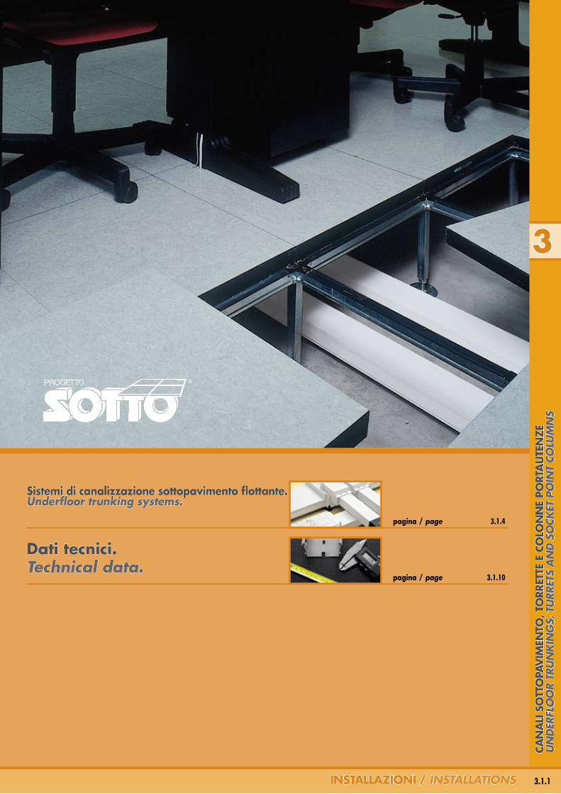
Sistemi di canalizzazione sottopavimento flottante. Underfloor trunking systems.
pagina / page 3.1.10
pagina / page 3.1.4
Dati tecnici.Technical data.
3.1.1InSTallazIonI / insTallaTions
3
Can
alI
So
TTo
PaV
IMen
To, T
orr
eTTe
e C
olo
nn
e Po
rTa
uTe
nze
Un
der
flo
or
TrU
nk
ing
s, T
Urr
eTs
an
d s
ock
eT p
oin
T co
lUm
ns
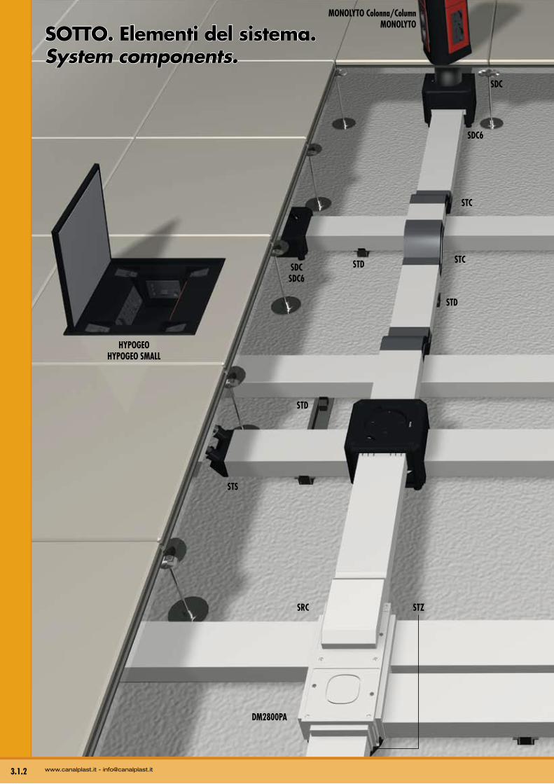
SoTTo. elementi del sistema. system components.
HYPOGEOHYPOGEO SMALL
STS
SRC
DM2800PA
STD
STD
STD
STC
STC
SDCSDC6
SDC
SDC6
MONOLYTO Colonna/ColumnMONOLYTO
STZ
3.1.2 www.canalplast.it - [email protected]
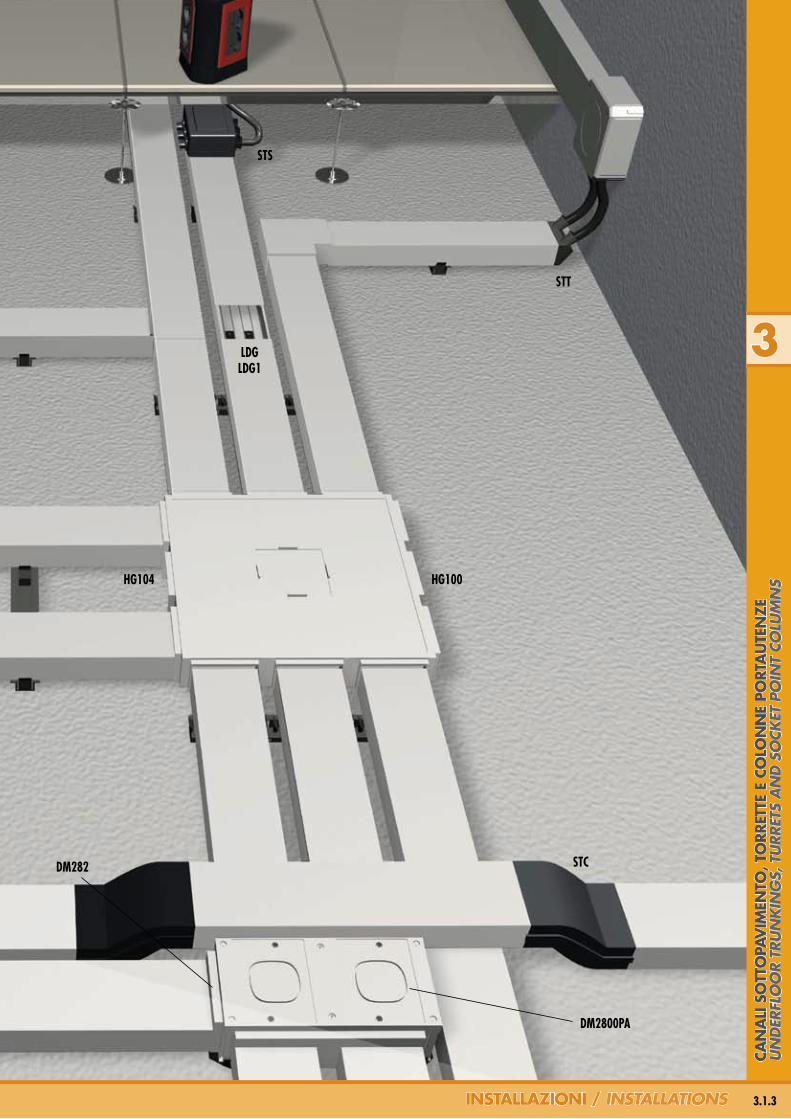
STS
STC
STT
HG100
LDGLDG1
HG104
DM2800PA
DM282
3
3.1.3InSTallazIonI / insTallaTions
Can
alI
So
TTo
PaV
IMen
To, T
orr
eTTe
e C
olo
nn
e Po
rTa
uTe
nze
Un
der
flo
or
TrU
nk
ing
s, T
Urr
eTs
an
d s
ock
eT p
oin
T co
lUm
ns
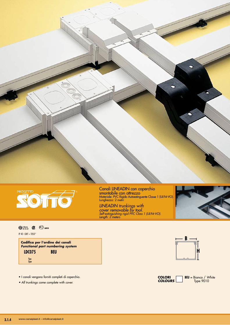
• I canali vengono forniti completi di coperchio.
• All trunkings come complete with cover.
Canali LINEADIN con coperchio smontabile con attrezzoMateriale: PVC Rigido Autoestinguente Classe 1 (UL94-VO).Lunghezza: 2 metri
LINEADIN trunkings with cover removable by tool.Self-extinguishing rigid PVC Class 1 (UL94-VO). Length: 2 meters
Codifica per l’ordine dei canali functional part numbering system
LDC075 BEU Tipo Type
B
H
ColorI BEU = Bianco / WhitecoloUrs Type 9010
3.1.4
IP 40 - GWT = T850°
A NormeCEI 23-32
www.canalplast.it - [email protected]
®
3
3.1.5
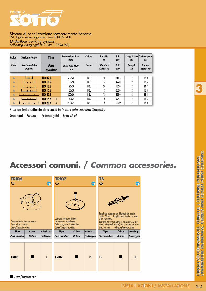
Sistema di canalizzazione sottopavimento flottante. PVC Rigido Autoestinguente Classe 1 (UL94-VO).Underfloor trunking systems. Self-extinguishing rigid PVC Class 1 (UL94-VO).
Guide Sezione fondo Tipo Dimensioni BxHmm
Colore Imballom
S.G.mm2
Lung. barre m
Cartone peso Kg
Rails Section of the bottom
Part number
Duct Size BxHmm
Colour Standard Carton m
G.S.mm2
Lengthm
CartonWeight Kg
LDC075 75x50 BEU 20 3115 2 18,0LDC105 100x50 BEU 16 4270 2 16,6LDC125 125x50 BEU 20 5350 2 24,7LDC155 150x50 BEU 12 6320 2 18,4LDC205 200x50 BEU 12 8590 2 23,8LDC157 * 150x75 BEU 8 9945 2 14,5LDC207 * 200x75 BEU 8 13465 2 18,0
InSTallazIonI / insTallaTions
®
* Usare per dorsali e tratti lineari ad elevata capacità. Use for main or upright stretch with an high capability.
TS
Tassello ad espansione per il fissaggio dei canali a parete, 2-3 per m. Completamente isolato, con testa vite a scomparsa. Wall plug. For wall-mounting of the ducting (2-3 per meter). Completely isolated, with a countersunk screw. Dim.: Ø 6 mm Colore/Colour: Nero/Black
TrI07
Coperchio di chiusura del foro sul pavimento sopraelevato.Hole-closing cover in raised floor.Colore/Colour: Nero/Black
TrI06
Cassetta di derivazione per torrette.Junction box for turrets.Colore/Colour: Nero/Black
TRI06 4
accessori comuni. / common accessories.
Tipo Colore Imballo pz.
Part number Colour Packing pcs.
Tipo Colore Imballo pz.
Part number Colour Packing pcs.
Tipo Colore Imballo pz.
Part number Colour Packing pcs.
TRI07 12 TS 100
Sezione piana Flat section Sezione con guida Section with rail
= Nero / Black Type 9017
Can
alI
So
TTo
PaV
IMen
To, T
orr
eTTe
e C
olo
nn
e Po
rTa
uTe
nze
Un
der
flo
or
TrU
nk
ing
s, T
Urr
eTs
an
d s
ock
eT p
oin
T co
lUm
ns
3.1.6
Canali con guide sul fondo. Trunkings with rails on the bottom.
Guide Tipo Colore BxH mm
Rails Part number Colour BxH mm
= Grigio chiaro / Light grey Type 7035 BEU = Bianco / White Type 9010 = Nero / Black Type 9017
www.canalplast.it - [email protected]
STD
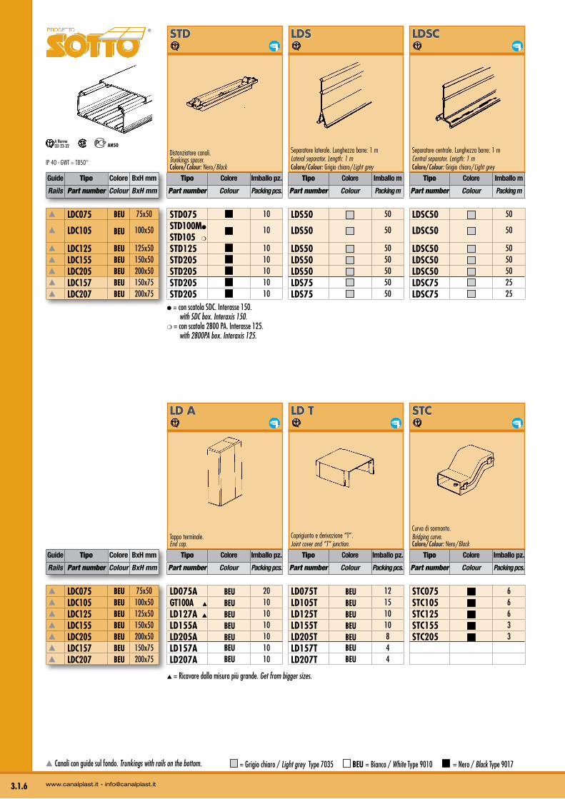
Distanziatore canali.Trunkings spacer. Colore/Colour: Nero/Black
lDS
Separatore laterale. Lunghezza barre: 1 mLateral separator. Length: 1 mColore/Colour: Grigio chiaro/Light grey
lDSC
Separatore centrale. Lunghezza barre: 1 mCentral separator. Length: 1 mColore/Colour: Grigio chiaro/Light grey
®
IP 40 - GWT = T850°
A NormeCEI 23-32
● = con scatola SDC. Interasse 150. with SDC box. Interaxis 150.❍ = con scatola 2800 PA. Interasse 125. with 2800PA box. Interaxis 125.
Tipo Colore Imballo pz.
Part number Colour Packing pcs.
Tipo Colore Imballo m
Part number Colour Packing m
Tipo Colore Imballo m
Part number Colour Packing m
LDC075 BEU 75x50
LDC105 BEU 100x50
LDC125 BEU 125x50 LDC155 BEU 150x50 LDC205 BEU 200x50 LDC157 BEU 150x75 LDC207 BEU 200x75
STD075 10STD100M●
STD105 ❍ 10
STD125 10STD205 10STD205 10STD205 10STD205 10
LDS50 50
LDS50 50
LDS50 50LDS50 50LDS50 50LDS75 50LDS75 50
LDSC50 50
LDSC50 50
LDSC50 50LDSC50 50LDSC50 50LDSC75 25LDSC75 25
lD a
Tappo terminale.End cap.
lD T
Coprigiunto e derivazione “T”.Joint cover and “T” junction.
STC
Curva di sormonto.Bridging curve.Colore/Colour: Nero/Black
Guide Tipo Colore BxH mm
Rails Part number Colour BxH mm
LDC075 BEU 75x50 LDC105 BEU 100x50 LDC125 BEU 125x50 LDC155 BEU 150x50 LDC205 BEU 200x50 LDC157 BEU 150x75 LDC207 BEU 200x75
Tipo Colore Imballo pz.
Part number Colour Packing pcs.
Tipo Colore Imballo pz.
Part number Colour Packing pcs.
Tipo Colore Imballo pz.
Part number Colour Packing pcs.
LD075A BEU 20GT100A ▲ BEU 10LD127A ▲ BEU 10LD155A BEU 10LD205A BEU 10LD157A BEU 10LD207A BEU 10
LD075T BEU 12LD105T BEU 15LD125T BEU 10LD155T BEU 10LD205T BEU 8LD157T BEU 4LD207T BEU 4
STC075 6STC105 6STC125 6STC155 3STC205 3
▲ = Ricavare dalla misura più grande. Get from bigger sizes.
3
3.1.7InSTallazIonI / insTallaTions
DMF 100 (2x50)
DMF 100 (2x50)
DMF 100 (2x50)DMF 100 (2x50)DMF 100 (2x50)DMF 100 (2x50)DMF 100 (2x50)
LDG50 20
LDG50 20
LDG50 20LDG50 20LDG50 20LDG75 20LDG75 20
LDG1 25 (5x5)
LDG1 25 (5x5)
LDG1 25 (5x5)LDG1 25 (5x5)LDG1 25 (5x5)LDG1 25 (5x5)LDG1 25 (5x5)
LD075L BEU 20
LD105L BEU 10
LD125L BEU 8LD155L BEU 10LD205L BEU 4LD157L BEU 4LD207L BEU 4
DMF
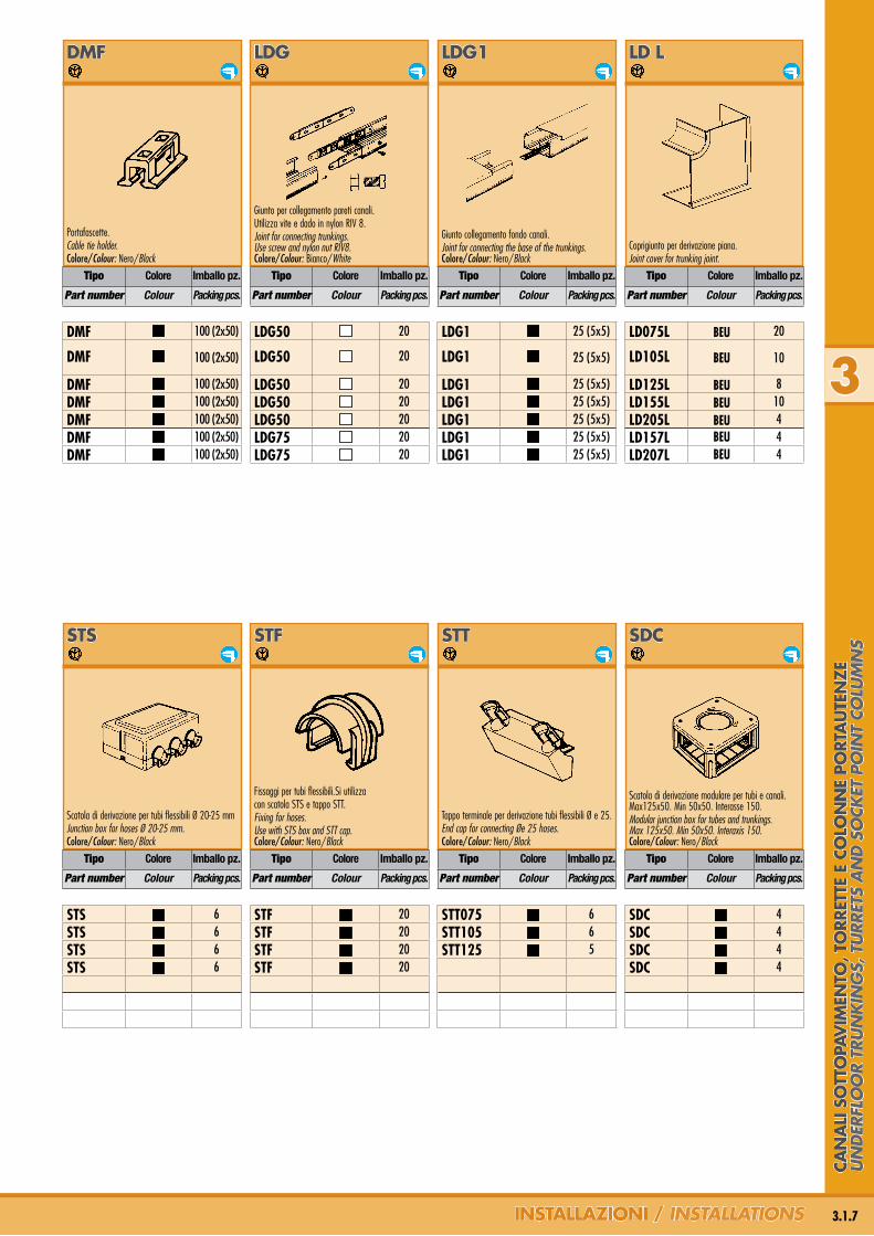
Portafascette.Cable tie holder.Colore/Colour: Nero/Black
lDG
Giunto per collegamento pareti canali.Utilizza vite e dado in nylon RIV 8.Joint for connecting trunkings. Use screw and nylon nut RIV8.Colore/Colour: Bianco/White
lDG1
Giunto collegamento fondo canali.Joint for connecting the base of the trunkings.Colore/Colour: Nero/Black
lD l
Coprigiunto per derivazione piana.Joint cover for trunking joint.
Tipo Colore Imballo pz.
Part number Colour Packing pcs.
Tipo Colore Imballo pz.
Part number Colour Packing pcs.
Tipo Colore Imballo pz.
Part number Colour Packing pcs.
Tipo Colore Imballo pz.
Part number Colour Packing pcs.
STS
Scatola di derivazione per tubi flessibili Ø 20-25 mmJunction box for hoses Ø 20-25 mm.Colore/Colour: Nero/Black
STF
Fissaggi per tubi flessibili.Si utilizzacon scatola STS e tappo STT.Fixing for hoses.Use with STS box and STT cap.Colore/Colour: Nero/Black
STT
Tappo terminale per derivazione tubi flessibili Ø e 25.End cap for connecting Øe 25 hoses.Colore/Colour: Nero/Black
SDC
Scatola di derivazione modulare per tubi e canali. Max125x50. Min 50x50. Interasse 150.Modular junction box for tubes and trunkings. Max 125x50. Min 50x50. Interaxis 150.Colore/Colour: Nero/Black
Tipo Colore Imballo pz.
Part number Colour Packing pcs.
Tipo Colore Imballo pz.
Part number Colour Packing pcs.
Tipo Colore Imballo pz.
Part number Colour Packing pcs.
Tipo Colore Imballo pz.
Part number Colour Packing pcs.
STS 6STS 6STS 6STS 6
STF 20STF 20STF 20STF 20
STT075 6STT105 6STT125 5
SDC 4SDC 4SDC 4SDC 4
Can
alI
So
TTo
PaV
IMen
To, T
orr
eTTe
e C
olo
nn
e Po
rTa
uTe
nze
Un
der
flo
or
TrU
nk
ing
s, T
Urr
eTs
an
d s
ock
eT p
oin
T co
lUm
ns
3.1.8 www.canalplast.it - [email protected]
IP 40 - GWT = T850°
A NormeCEI 23-32
Tipo Colore Imballo pz.
Part number Colour Packing pcs.
Tipo Colore Imballo pz.
Part number Colour Packing pcs.
Tipo Colore Imballo pz.
Part number Colour Packing pcs.
Tipo Colore Imballo pz.
Part number Colour Packing pcs.
Tipo Colore Imballo pz.
Part number Colour Packing pcs.
Tipo Colore Imballo pz.
Part number Colour Packing pcs.
DM2803 6DM2803 6DM2803 6DM2803 6DM2803 6DM2803 6DM2803 6
DM2804 2DM2804 2DM2804 2DM2804 2DM2804 2DM2804 2DM2804 2
DM2821 BEU 10DM2821 BEU 10DM2822 BEU 10DM2822 BEU 10DM2822 BEU 10DM2822 BEU 10DM2822 BEU 10
lDaD
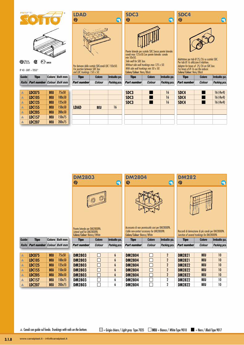
Per derivare dalla scatola SDCcanali LDC 150x50.For junction between SDC boxand LDC trunkings 150 x 50.
SDC3
Parete laterale per scatola SDC.Senza parete laterale: canali max 125x50.Con parete laterale: canale min 50x50.Side wall for SDC box. Without side wall trunkings max 125 x 50.With side wall trunkings min 50 x 50.Colore/Colour: Nero/Black
SDC4
Adattatore per tubi Ø 25/26 su scatola SDC. Per tubi Ø 16 utilizzare il riduttore.Adaptor for hoses of 25/26 on SDC box. For hoses of Ø 16 use the reducer.Colore/Colour: Nero/Black
LDAD BEU 16
SDC3 16SDC3 16SDC3 16
SDC4 16 (4x4)SDC4 16 (4x4)SDC4 16 (4x4)
DM2803
Parete laterale per DM2800PA.Lateral wall for DM2800PA.Colore/Colour: Bianco/White
DM2804
Accessorio di non promiscuità cavi per DM2800PA.Cable non-contact accessory for DM2800PA.Colore/Colour: Bianco/White
DM282
Raccordi di derivazione di più canali per DM2800PA.Junction of several trunkings for DM2800PA.
®
Guide Tipo Colore BxH mm
Rails Part number Colour BxH mm
Guide Tipo Colore BxH mm
Rails Part number Colour BxH mm
LDC075 BEU 75x50 LDC105 BEU 100x50 LDC125 BEU 125x50 LDC155 BEU 150x50 LDC205 BEU 200x50 LDC157 BEU 150x75 LDC207 BEU 200x75
LDC075 BEU 75x50 LDC105 BEU 100x50 LDC125 BEU 125x50 LDC155 BEU 150x50 LDC205 BEU 200x50 LDC157 BEU 150x75 LDC207 BEU 200x75
Canali con guide sul fondo. Trunkings with rails on the bottom. = Grigio chiaro / Light grey Type 7035 BEU = Bianco / White Type 9010 = Nero / Black Type 9017
3
3.1.9InSTallazIonI / insTallaTions
Tipo Colore Imballo pz.
Part number Colour Packing pcs.
Tipo Colore Imballo pz.
Part number Colour Packing pcs.
Tipo Colore Imballo pz.
Part number Colour Packing pcs.
Tipo Colore Imballo pz.
Part number Colour Packing pcs.
Tipo Colore Imballo pz.
Part number Colour Packing pcs.
Tipo Colore Imballo pz.
Part number Colour Packing pcs.
Tipo Colore Imballo pz.
Part number Colour Packing pcs.
Tipo Colore Imballo pz.
Part number Colour Packing pcs.
STZ 6STZ 6STZ 6STZ 6STZ 6STZ 6STZ 6
SRC 6SRC 6 HG100 ❍ 1 HG104 12
SDC5
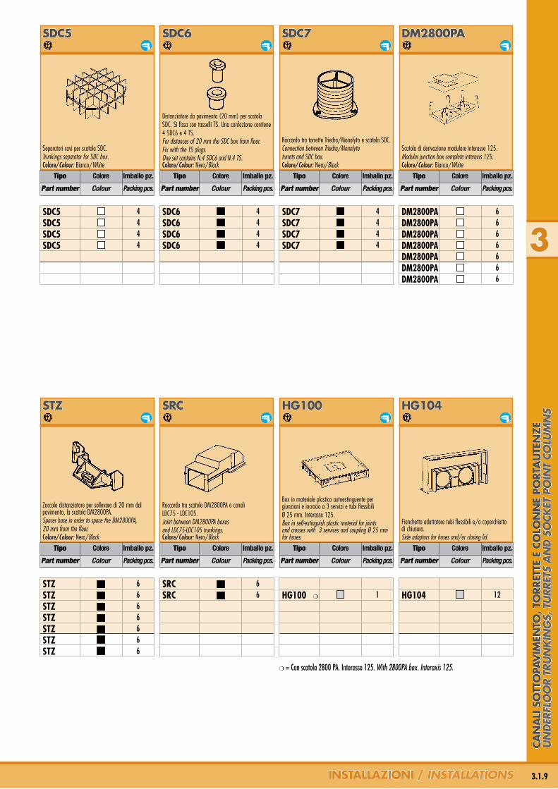
Separatori cavi per scatola SDC.Trunkings separator for SDC box.Colore/Colour: Bianco/White
SDC6
Distanziatore da pavimento (20 mm) per scatolaSDC. Si fissa con tasselli TS. Una confezione contiene4 SDC6 e 4 TS.For distances of 20 mm the SDC box from floor.Fix with the TS plugs.One set contains N.4 SDC6 and N.4 TS.Colore/Colour: Nero/Black
SDC7
Raccordo tra torrette Triedra/Monolyto e scatola SDC.Connection between Triedra/Monolytoturrets and SDC box.Colore/Colour: Nero/Black
DM2800Pa
Scatola di derivazione modulare interasse 125.Modular junction box complete interaxis 125.Colore/Colour: Bianco/White
SDC5 4SDC5 4SDC5 4SDC5 4
SDC6 4SDC6 4SDC6 4SDC6 4
SDC7 4SDC7 4SDC7 4SDC7 4
DM2800PA 6DM2800PA 6DM2800PA 6DM2800PA 6DM2800PA 6DM2800PA 6DM2800PA 6
STz
Zoccolo distanziatore per sollevare di 20 mm dal pavimento, la scatola DM2800PA.Spacer base in order to space the DM2800PA,20 mm from the floor.Colore/Colour: Nero/Black
SrC
Raccordo tra scatole DM2800PA e canaliLDC75 - LDC105.Joint between DM2800PA boxesand LDC75-LDC105 trunkings.Colore/Colour: Nero/Black
HG100
Box in materiale plastico autoestinguente per giunzioni e incrocio a 3 servizi e tubi flessibiliØ 25 mm. Interasse 125.Box in self-extinguish plastic material for joints and crosses with 3 services and coupling Ø 25 mm for hoses.
HG104
Fianchetto adattatore tubi flessibili e/o coperchietto di chiusura. Side adaptors for hoses and/or closing lid.
❍ = Con scatola 2800 PA. Interasse 125. With 2800PA box. Interaxis 125.
Can
alI
So
TTo
PaV
IMen
To, T
orr
eTTe
e C
olo
nn
e Po
rTa
uTe
nze
Un
der
flo
or
TrU
nk
ing
s, T
Urr
eTs
an
d s
ock
eT p
oin
T co
lUm
ns
STD
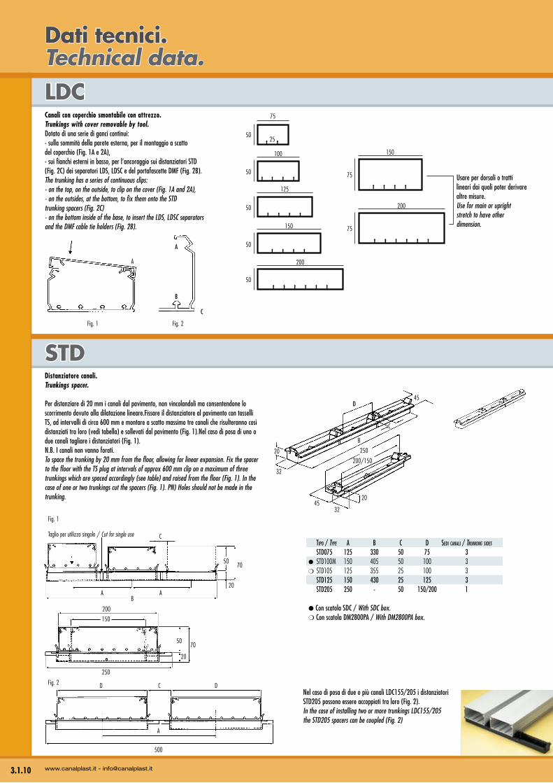
lDCCanali con coperchio smontabile con attrezzo.Trunkings with cover removable by tool.Dotato di una serie di ganci continui:- sulla sommità della parete esterna, per il montaggio a scatto del coperchio (Fig. 1A e 2A),- sui fianchi esterni in basso, per l’ancoraggio sui distanziatori STD (Fig. 2C) dei separatori LDS, LDSC e del portafascette DMF (Fig. 2B).The trunking has a series of continuous clips:- on the top, on the outside, to clip on the cover (Fig. 1A and 2A), - on the outsides, at the bottom, to fix them onto the STDtrunking spacers (Fig. 2C)- on the bottom inside of the base, to insert the LDS, LDSC separatorsand the DMF cable tie holders (Fig. 2B).
3.1.10 www.canalplast.it - [email protected]
Dati tecnici.Technical data.
Usare per dorsali o tratti lineari dai quali poter derivare altre misure.Use for main or uprightstretch to have other dimension.
Fig. 1
A
A
B
C
Fig. 2
75
150
75
200
100
50
125
50
50
150
50
200
50
75
25
D
B
45
C
20
32
250
4532
20
200/150
50
20
70
150
250
200
Fig. 1
C
AB
A20
5070
Taglio per utilizzo singolo / Cut for single use
DFig. 2 C D
A
500
Nel caso di posa di due o più canali LDC155/205 i distanziatori STD205 possono essere accoppiati tra loro (Fig. 2).In the case of installing two or more trunkings LDC155/205 the STD205 spacers can be coupled (Fig. 2)
Tipo / Type A B C D SeDi CAnAli / Trunking sides
STD075 125 330 50 75 3● STD100M 150 405 50 100 3❍ STD105 125 355 25 100 3 STD125 150 430 25 125 3 STD205 250 - 50 150/200 1
● Con scatola SDC / With SDC box.❍ Con scatola DM2800PA / With DM2800PA box.
Distanziatore canali.Trunkings spacer.
Per distanziare di 20 mm i canali dal pavimento, non vincolandoli ma consentendone lo scorrimento dovuto alla dilatazione lineare.Fissare il distanziatore al pavimento con tasselli TS, ad intervalli di circa 600 mm e montare a scatto massimo tre canali che risulteranno così distanziati tra loro (vedi tabella) e sollevati dal pavimento (Fig. 1).Nel caso di posa di uno o due canali tagliare i distanziatori (Fig. 1).N.B. I canali non vanno forati.To space the trunking by 20 mm from the floor, allowing for linear expansion. Fix the spacer to the floor with the TS plug at intervals of approx 600 mm clip on a maximum of three trunkings which are spaced accordingly (see table) and raised from the floor (Fig. 1). In the case of one or two trunkings cut the spacers (Fig. 1). PN) Holes should not be made in the trunking.
200
25
2550
50RIV8
25
lDG
lDG1
lDl
lDa
DMF
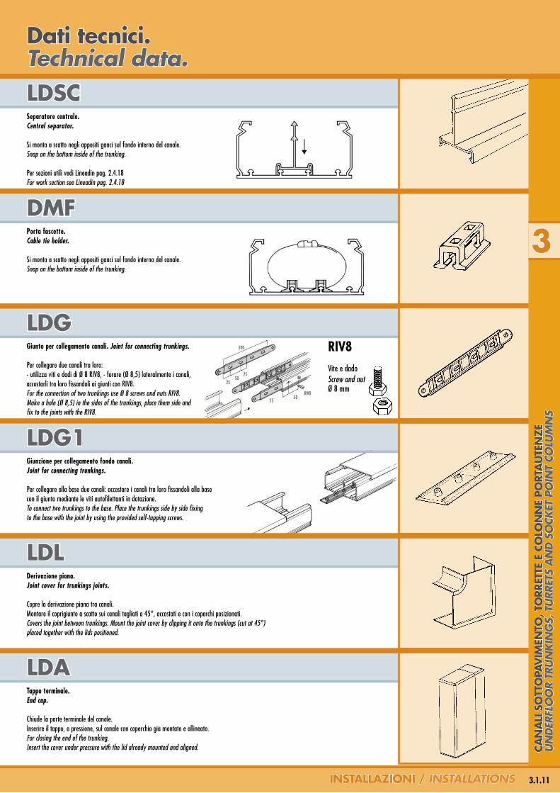
lDSCSeparatore centrale.Central separator.
Si monta a scatto negli appositi ganci sul fondo interno del canale.Snap on the bottom inside of the trunking.
Per sezioni utili vedi Lineadin pag. 2.4.18For work section see Lineadin pag. 2.4.18
Porta fascette.Cable tie holder.
Si monta a scatto negli appositi ganci sul fondo interno del canale.Snap on the bottom inside of the trunking.
3
3.1.11InSTallazIonI / insTallaTions
Dati tecnici.Technical data.
RIV8Vite e dado Screw and nut Ø 8 mm
Giunto per collegamento canali. Joint for connecting trunkings.
Per collegare due canali tra loro:- utilizza viti e dadi di Ø 8 RIV8, - forare (Ø 8,5) lateralmente i canali, accostarli tra loro fissandoli ai giunti con RIV8.For the connection of two trunkings use Ø 8 screws and nuts RIV8. Make a hole (Ø 8,5) in the sides of the trunkings, place them side and fix to the joints with the RIV8.
Giunzione per collegamento fondo canali.Joint for connecting trunkings.
Per collegare alla base due canali: accostare i canali tra loro fissandoli alla base con il giunto mediante le viti autofilettanti in dotazione.To connect two trunkings to the base. Place the trunkings side by side fixing to the base with the joint by using the provided self-tapping screws.
Derivazione piana.Joint cover for trunkings joints.
Copre la derivazione piana tra canali. Montare il coprigiunto a scatto sui canali tagliati a 45°, accostati e con i coperchi posizionati.Covers the joint between trunkings. Mount the joint cover by clipping it onto the trunkings (cut at 45°) placed together with the lids positioned.
Tappo terminale.End cap.
Chiude la parte terminale del canale.Inserire il tappo, a pressione, sul canale con coperchio già montato e allineato.For closing the end of the trunking. Insert the cover under pressure with the lid already mounted and aligned. Ca
na
lI S
oTT
oPa
VIM
enTo
, To
rreT
Te e
Co
lon
ne
PorT
au
Ten
ze
Un
der
flo
or
TrU
nk
ing
s, T
Urr
eTs
an
d s
ock
eT p
oin
T co
lUm
ns
STT
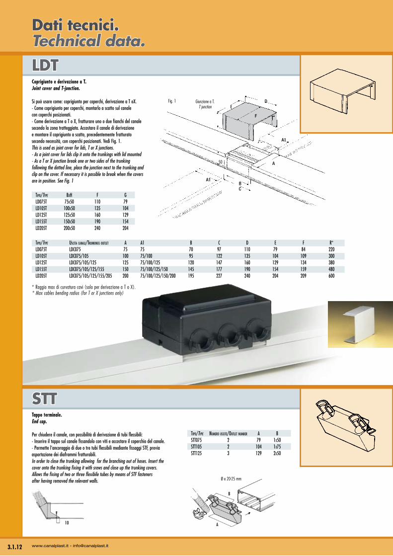
lDTCoprigiunto e derivazione a T.Joint cover and T-junction.
Si può usare come: coprigiunto per coperchi, derivazione a T oX.- Come coprigiunto per coperchi, montarlo a scatto sul canale con coperchi posizionati.- Come derivazione a T o X, fratturare uno o due fianchi del canale secondo la zona tratteggiata. Accostare il canale di derivazione e montare il coprigiunto a scatto, precedentemente fratturato secondo necessità, con coperchi posizionati. Vedi Fig. 1.This is used as joint cover for lids, T or X junctions. - As a joint cover for lids clip it onto the trunkings with lid mounted- As a T or X junction break one or two sides of the trunking following the dotted line, place the junction next to the trunking and clip on the cover. If necessary it is possible to break when the covers are in position. See Fig. 1
3.1.12 www.canalplast.it - [email protected]
Dati tecnici.Technical data.
Tipo/Type BxH F G lD075T 75x50 110 79 lD105T 100x50 135 104 lD125T 125x50 160 129 lD155T 150x50 190 154 lD205T 200x50 240 204
Tipo/Type USCiTA CAnAli/TrUnkinGS oUTleT A A1 B C D e F r* lD075T lDC075 75 75 70 97 110 79 84 220 lD105T lDC075/105 100 75/100 95 122 135 104 109 300 lD125T lDC075/105/125 125 75/100/125 120 147 160 129 134 380 lD155T lDC075/105/125/155 150 75/100/125/150 145 177 190 154 159 480 lD205T lDC075/105/125/155/205 200 75/100/125/150/200 195 227 240 204 209 600
* Raggio max di curvatura cavi (solo per derivazione a T o X).* Max cables bending radius (for T or X junctions only)
F
50
A1
A1
A
BC
EDGiunzione a T.
T junctionFig. 1
Tappo terminale.End cap.
Per chiudere il canale, con possibilità di derivazione di tubi flessibili:- Inserire il tappo sul canale fissandolo con viti e accostare il coperchio del canale.- Permette l’ancoraggio di due o tre tubi flessibili mediante fissaggi STF, previa asportazione dei diaframmi fratturabili.In order to close the trunking allowing for the branching out of hoses. Insert the cover onto the trunking fixing it with srews and close up the trunking covers.Allows the fixing of two or three flexibile tubes by means of STF fastenersafter having removed the relevant walls.
10
B
A
Ø e 20-25 mm
Tipo/Type nUmero USCiTe/oUTleT nUmBer A B STT075 2 79 1x50 STT105 2 104 1x75 STT125 3 129 2x50
Øe 20 mm
Øe 25 mm
42
54
106
A
42
158
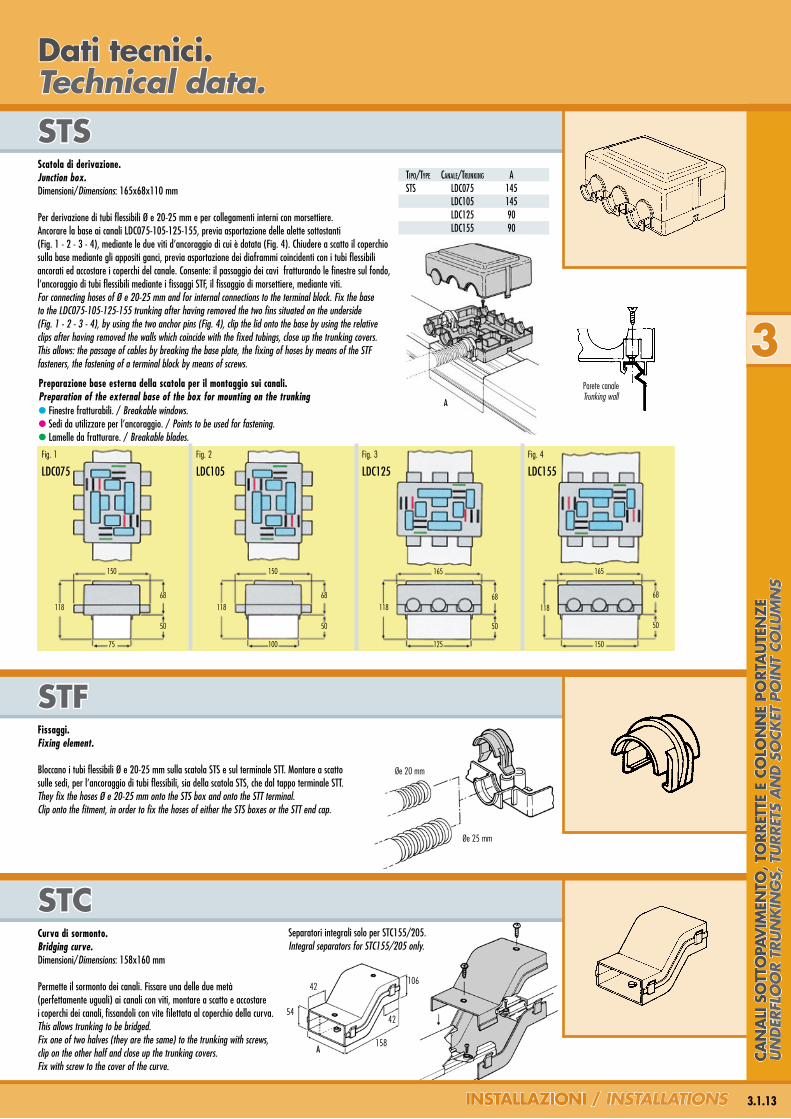
STCCurva di sormonto.Bridging curve.Dimensioni/Dimensions: 158x160 mm
Permette il sormonto dei canali. Fissare una delle due metà(perfettamente uguali) ai canali con viti, montare a scatto e accostarei coperchi dei canali, fissandoli con vite filettata al coperchio della curva.This allows trunking to be bridged. Fix one of two halves (they are the same) to the trunking with screws, clip on the other half and close up the trunking covers. Fix with screw to the cover of the curve.
STFFissaggi.Fixing element.
Bloccano i tubi flessibili Ø e 20-25 mm sulla scatola STS e sul terminale STT. Montare a scatto sulle sedi, per l’ancoraggio di tubi flessibili, sia della scatola STS, che dal tappo terminale STT.They fix the hoses Ø e 20-25 mm onto the STS box and onto the STT terminal. Clip onto the fitment, in order to fix the hoses of either the STS boxes or the STT end cap.
STSScatola di derivazione.Junction box.Dimensioni/Dimensions: 165x68x110 mm
Per derivazione di tubi flessibili Ø e 20-25 mm e per collegamenti interni con morsettiere. Ancorare la base ai canali LDC075-105-125-155, previa asportazione delle alette sottostanti (Fig. 1 - 2 - 3 - 4), mediante le due viti d’ancoraggio di cui è dotata (Fig. 4). Chiudere a scatto il coperchio sulla base mediante gli appositi ganci, previa asportazione dei diaframmi coincidenti con i tubi flessibili ancorati ed accostare i coperchi del canale. Consente: il passaggio dei cavi fratturando le finestre sul fondo, l’ancoraggio di tubi flessibili mediante i fissaggi STF, il fissaggio di morsettiere, mediante viti.For connecting hoses of Ø e 20-25 mm and for internal connections to the terminal block. Fix the base to the LDC075-105-125-155 trunking after having removed the two fins situated on the underside (Fig. 1 - 2 - 3 - 4), by using the two anchor pins (Fig. 4), clip the lid onto the base by using the relative clips after having removed the walls which coincide with the fixed tubings, close up the trunking covers. This allows: the passage of cables by breaking the base plate, the fixing of hoses by means of the STF fasteners, the fastening of a terminal block by means of screws.
3
3.1.13InSTallazIonI / insTallaTions
Dati tecnici.Technical data.
Tipo/Type CAnAle/TrUnkinG A STS lDC075 145 lDC105 145 lDC125 90 lDC155 90
Parete canaleTrunking wall
● Finestre fratturabili. / Breakable windows.● Sedi da utilizzare per l’ancoraggio. / Points to be used for fastening.● Lamelle da fratturare. / Breakable blades.
Preparazione base esterna della scatola per il montaggio sui canali.Preparation of the external base of the box for mounting on the trunking
A
LDC075 LDC105 LDC125 LDC155
Fig. 1
150
118
68
50
150
118
68
50
165
11868
50
165
118
68
50
Fig. 2 Fig. 3 Fig. 4
75 100 125 150
Separatori integrali solo per STC155/205.Integral separators for STC155/205 only.
Can
alI
So
TTo
PaV
IMen
To, T
orr
eTTe
e C
olo
nn
e Po
rTa
uTe
nze
Un
der
flo
or
TrU
nk
ing
s, T
Urr
eTs
an
d s
ock
eT p
oin
T co
lUm
ns
SDC6Distanziatore da pavimento.Floor spacer.
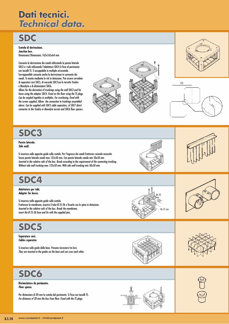
Per distanziare di 20 mm la scatola dal pavimento. Si fissa con tasselli TS. For distances of 20 mm the box from floor. Fixed with the TS plugs.
Øe 20 mm
Øe 25 mm
SDC5Separatore cavi.Cables separator.
Si inserisce sulle guide della base. Possono incrociarsi tra loro.They are inserted in the guides on the base and can cross each other.
Parete laterale.Side wall.
Si inserisce nelle apposite guide sulla scatola. Per l’ingresso dei canali fratturare secondo necessità. Senza parete laterale canali max 125x50 mm. Con parete laterale canale min 50x50 mmInserted in the relative rails of the box. Break according to the requirement of the connecting trunking. Without side wall trunking max 125x50 mm. With side wall trunking min 50x50 mm.
SDC4Adattatore per tubi.Adaptor for hoses.
Si inserisce nelle apposite guide sulla scatola.Fratturare la membrana, inserire il tubo Ø 25-26 e fissarlo con le spine in dotazione. Inserted in the relative rails of the box. Break the membrane,insert the Ø 25-26 hose and fix with the supplied pins.
SDC3
SDCScatola di derivazione.Junction box. Dimensioni/Dimensions: 165x165x64 mm
Consente la derivazione dei canali utilizzando la parete laterale SDC3 e i tubi utilizzando l’adattatore SDC4.Si fissa al pavimento con tasselli TS. È accoppiabile in multiplo orizzontale. Sovrapponibile consente anche la derivazione in sormonto dei canali. Si monta mediante le viti in dotazione. Può essere corredata di separatori cavi SDC5, di raccordo SDC7con le torrette Triedra o Monolyto e di distanziatori SDC6. Allows for the derivation of trunkings using the wall SDC3 and for hoses using the adaptor SDC4. Fixed on the floor using the TS plugs. Can be coupled together in multiples. For overlaying, fixed with the screws supplied. Allows the connection to trunkings assembled above. Can be supplied with SDC5 cable separators, of SDC7 direct connector to the Triedra or Monolyto turrets and SDC6 floor spacers.
3.1.14 www.canalplast.it - [email protected]
Dati tecnici.Technical data.
150
165
STD125
125 125 125
150 150
165
150
150
125
125
125
150
150
100 100 100
150 150
165
100
100
100 165
STD100M
75 75 75
125 125
165
16575
75
75
125
125
STD075
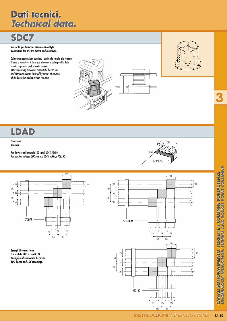
lDaDGiunzione.Junction.
Per derivare dalla scatola SDC canali LDC 150x50.For junction between SDC box and LDC trunkings 150x50.
SDC7Raccordo per torretta Triedra e Monolyto.Connection for Triedra turret and Monolyto.
Collega con separazione continua i cavi dalla scatola alle torrette Triedra e Monolyto. Si inserisce a baionetta sul coperchio della scatola dopo aver prefratturato la sede.After separating the cables connect the box to the and Monolyto turrets. Inserted by means of bayonet of the box after having broken the base.
3
3.1.15InSTallazIonI / insTallaTions
Dati tecnici.Technical data.
SDC
LDAD
LDC 150x50
Esempi di connessione tra scatole SDC e canali LDC.Exemples of connection between SDC boxes and LDC trunkings.
Can
alI
So
TTo
PaV
IMen
To, T
orr
eTTe
e C
olo
nn
e Po
rTa
uTe
nze
Un
der
flo
or
TrU
nk
ing
s, T
Urr
eTs
an
d s
ock
eT p
oin
T co
lUm
ns
DM2821
DM2821 DM2822
75-10075-10075-100
75200
50
50
100
DM2803
30 max
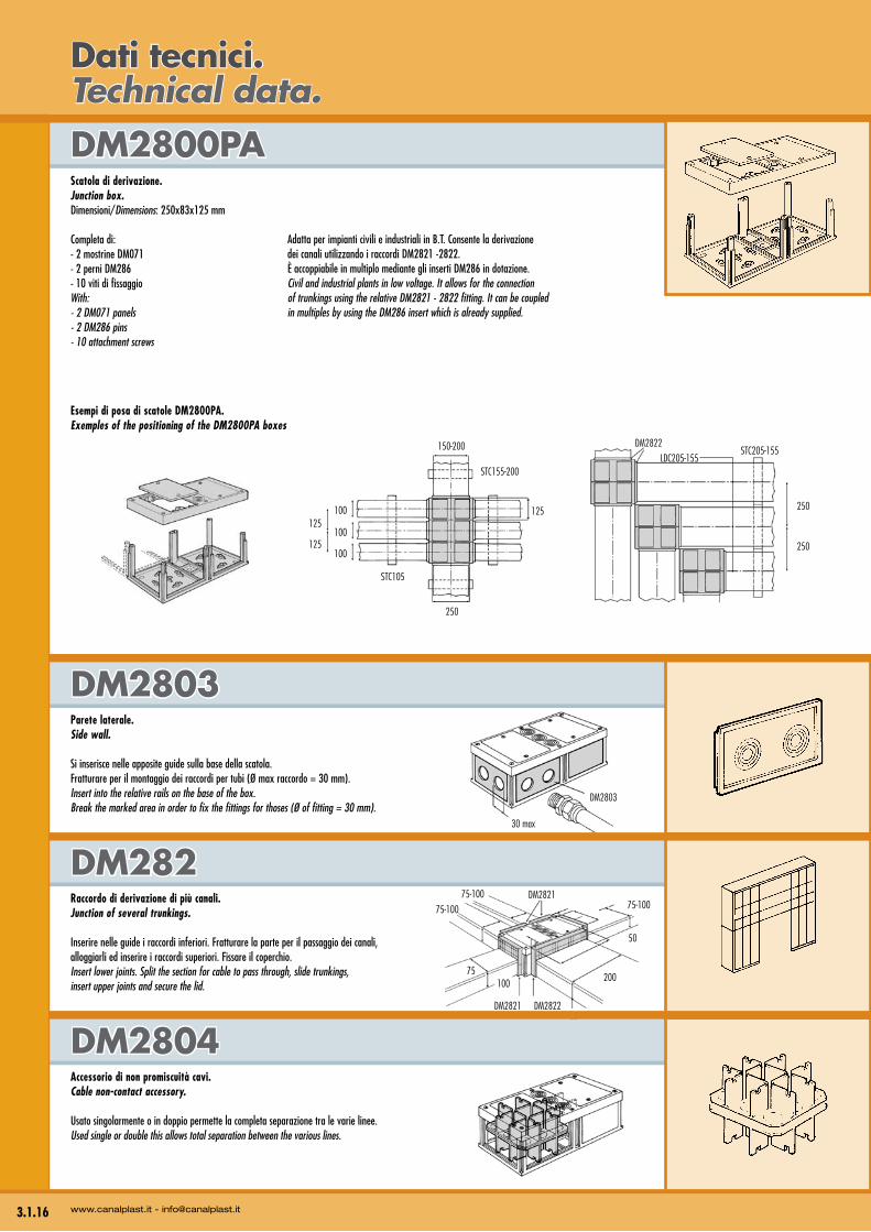
DM2804Accessorio di non promiscuità cavi.Cable non-contact accessory.
Usato singolarmente o in doppio permette la completa separazione tra le varie linee.Used single or double this allows total separation between the various lines.
DM282Raccordo di derivazione di più canali.Junction of several trunkings.
Inserire nelle guide i raccordi inferiori. Fratturare la parte per il passaggio dei canali, alloggiarli ed inserire i raccordi superiori. Fissare il coperchio.Insert lower joints. Split the section for cable to pass through, slide trunkings, insert upper joints and secure the lid.
DM2803Parete laterale.Side wall.
Si inserisce nelle apposite guide sulla base della scatola. Fratturare per il montaggio dei raccordi per tubi (Ø max raccordo = 30 mm).Insert into the relative rails on the base of the box. Break the marked area in order to fix the fittings for thoses (Ø of fitting = 30 mm).
DM2800PaScatola di derivazione.Junction box.Dimensioni/Dimensions: 250x83x125 mm
Completa di: - 2 mostrine DM071- 2 perni DM286 - 10 viti di fissaggioWith: - 2 DM071 panels- 2 DM286 pins- 10 attachment screws
3.1.16 www.canalplast.it - [email protected]
Dati tecnici.Technical data.
Esempi di posa di scatole DM2800PA.Exemples of the positioning of the DM2800PA boxes
Adatta per impianti civili e industriali in B.T. Consente la derivazione dei canali utilizzando i raccordi DM2821 -2822. È accoppiabile in multiplo mediante gli inserti DM286 in dotazione.Civil and industrial plants in low voltage. It allows for the connection of trunkings using the relative DM2821 - 2822 fitting. It can be coupled in multiples by using the DM286 insert which is already supplied.
150-200
125
250
100
100
100125
125
STC155-200
STC105
250
250
STC205-155DM2822
LDC205-155
268
102
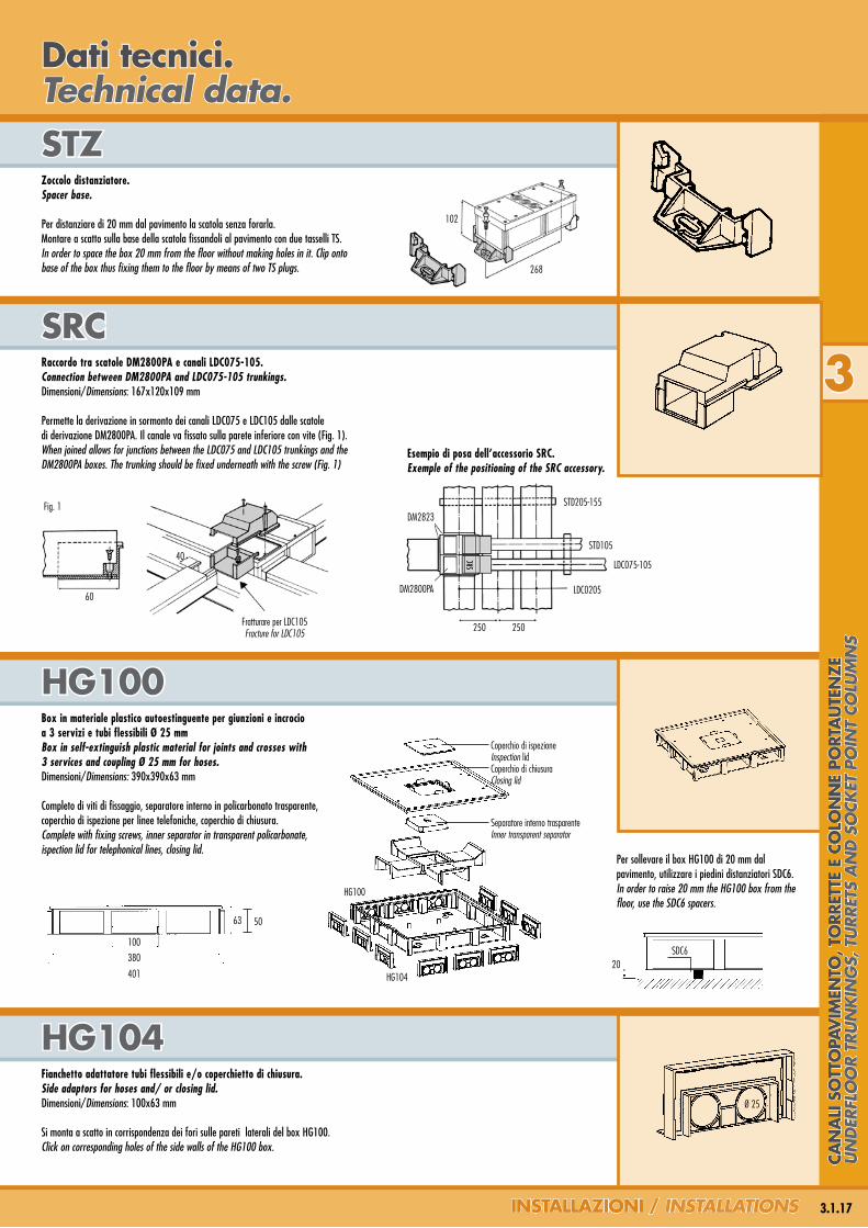
HG100Box in materiale plastico autoestinguente per giunzioni e incrocio a 3 servizi e tubi flessibili Ø 25 mmBox in self-extinguish plastic material for joints and crosses with 3 services and coupling Ø 25 mm for hoses.Dimensioni/Dimensions: 390x390x63 mm
Completo di viti di fissaggio, separatore interno in policarbonato trasparente, coperchio di ispezione per linee telefoniche, coperchio di chiusura.Complete with fixing screws, inner separator in transparent policarbonate, ispection lid for telephonical lines, closing lid.
HG104Fianchetto adattatore tubi flessibili e/o coperchietto di chiusura.Side adaptors for hoses and/ or closing lid.Dimensioni/Dimensions: 100x63 mm
Si monta a scatto in corrispondenza dei fori sulle pareti laterali del box HG100.Click on corresponding holes of the side walls of the HG100 box.
SrCRaccordo tra scatole DM2800PA e canali LDC075-105.Connection between DM2800PA and LDC075-105 trunkings. Dimensioni/Dimensions: 167x120x109 mm
Permette la derivazione in sormonto dei canali LDC075 e LDC105 dalle scatole di derivazione DM2800PA. Il canale va fissato sulla parete inferiore con vite (Fig. 1).When joined allows for junctions between the LDC075 and LDC105 trunkings and the DM2800PA boxes. The trunking should be fixed underneath with the screw (Fig. 1)
STzZoccolo distanziatore.Spacer base.
Per distanziare di 20 mm dal pavimento la scatola senza forarla. Montare a scatto sulla base della scatola fissandoli al pavimento con due tasselli TS.In order to space the box 20 mm from the floor without making holes in it. Clip onto base of the box thus fixing them to the floor by means of two TS plugs.
3
3.1.17InSTallazIonI / insTallaTions
Dati tecnici.Technical data.
Fig. 1
60
40
Fratturare per LDC105Fracture for LDC105 250 250
STD205-155
LDC075-105
LDC0205
STD105
SRC
DM2823
Esempio di posa dell’accessorio SRC.Exemple of the positioning of the SRC accessory.
DM2800PA
Per sollevare il box HG100 di 20 mm dal pavimento, utilizzare i piedini distanziatori SDC6.In order to raise 20 mm the HG100 box from the floor, use the SDC6 spacers.
20SDC6
5063
100
380
401
Coperchio di ispezioneInspection lidCoperchio di chiusuraClosing lid
Separatore interno trasparenteInner transparent separator
HG100
HG104
Ø 25
Can
alI
So
TTo
PaV
IMen
To, T
orr
eTTe
e C
olo
nn
e Po
rTa
uTe
nze
Un
der
flo
or
TrU
nk
ing
s, T
Urr
eTs
an
d s
ock
eT p
oin
T co
lUm
ns
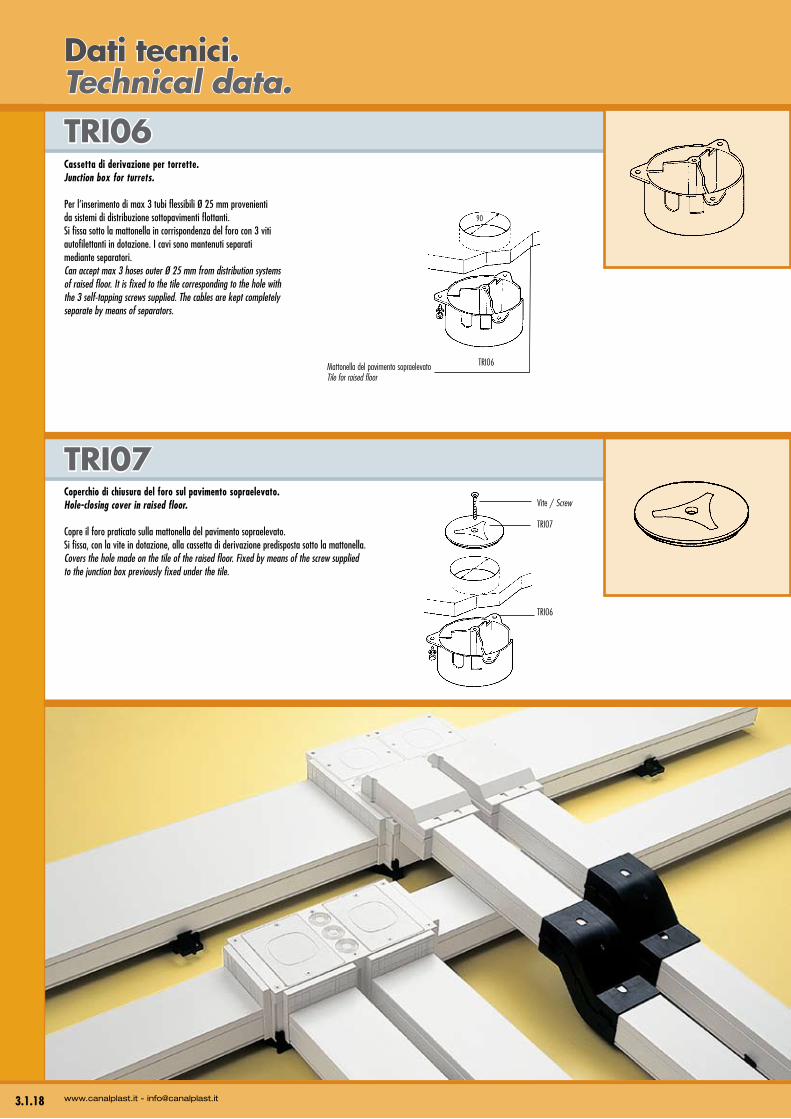
Coperchio di chiusura del foro sul pavimento sopraelevato.Hole-closing cover in raised floor.
Copre il foro praticato sulla mattonella del pavimento sopraelevato.Si fissa, con la vite in dotazione, alla cassetta di derivazione predisposta sotto la mattonella.Covers the hole made on the tile of the raised floor. Fixed by means of the screw supplied to the junction box previously fixed under the tile.
TrI07
TrI06Cassetta di derivazione per torrette.Junction box for turrets.
Per l’inserimento di max 3 tubi flessibili Ø 25 mm provenienti da sistemi di distribuzione sottopavimenti flottanti. Si fissa sotto la mattonella in corrispondenza del foro con 3 viti autofilettanti in dotazione. I cavi sono mantenuti separati mediante separatori.Can accept max 3 hoses outer Ø 25 mm from distribution systems of raised floor. It is fixed to the tile corresponding to the hole with the 3 self-tapping screws supplied. The cables are kept completely separate by means of separators.
3.1.18 www.canalplast.it - [email protected]
Dati tecnici.Technical data.
90
TRI06
Vite / Screw
TRI07
TRI06
Mattonella del pavimento sopraelevatoTile for raised floor