Embed Size (px)
Citation preview

© 2003 esd gmbh Hannover CAN-Wiring Notes Rev. 3.5
CAN - WiringNotes on the Wiring of CAN-Bus Systems and
the Cable Selection

© 2003 esd gmbh Hannover CAN-Wiring Notes Rev. 3.5
Document file: I:\texte\Doku\MANUALS\CAN\VERDRAHT\Englisch\CANKAB35.en9
Date of print: 22.08.2003
Order no.: C.1300.02
Changes in the Chapters
The changes in the user’s manual listed below affect changes in the hardware, as well as changes inthe description of the facts only.
Chapter Changes versus previous version
1.3.4 Chapter revised.
2.1 New graphic inserted.
2.3 Pin assignment of Combicon-style connector inserted.
4. List of available accessory extended.
Further technical changes are subject to change without notice.
© 2003 esd gmbh Hannover CAN-Wiring Notes Rev. 3.5
N O T E
The information in this document has been carefully checked and is believed to be entirely reliable. esdmakes no warranty of any kind with regard to the material in this document, and assumes noresponsibility for any errors that may appear in this document. esd reserves the right to make changeswithout notice to this, or any of its products, to improve reliability, performance or design.
esd assumes no responsibility for the use of any circuitry other than circuitry which is part of a productof esd gmbh.
esd does not convey to the purchaser of the product described herein any license under the patent rightsof esd gmbh nor the rights of others.
esd electronic system design gmbhVahrenwalder Str. 20730165 HannoverGermany
Phone: +49-511-372 98-0Fax: +49-511-372 98-68E-mail: [email protected]: www.esd-electronics.com
USA / Canada:esd electronics Inc.12 Elm StreetHatfield, MA 01038-0048USA
Phone: +1-800-732-8006Fax: +1-800-732-8093E-mail: [email protected]: www.esd-electronics.us
Contents Page
© 2003 esd gmbh Hannover CAN-Wiring Notes Rev. 3.5 1
1. Selecting Cables . . . . . . . . . . . . . . . . . . . . . . . . . . . . . . . . . . . . . . . . . . . . . . . . . . . . . . . . . . . . . . 31.1 Minimum Requirements . . . . . . . . . . . . . . . . . . . . . . . . . . . . . . . . . . . . . . . . . . . . . . . . . 31.2 Factors for the Selection of the Cable . . . . . . . . . . . . . . . . . . . . . . . . . . . . . . . . . . . . . . . 31.3 Limit Values for Cable Selection . . . . . . . . . . . . . . . . . . . . . . . . . . . . . . . . . . . . . . . . . . . 4
1.3.1 Cable Geometry . . . . . . . . . . . . . . . . . . . . . . . . . . . . . . . . . . . . . . . . . . . . . . . . 41.3.2 Effective Resistance of the Cable . . . . . . . . . . . . . . . . . . . . . . . . . . . . . . . . . . . 51.3.3 Effective Resistance of the DSUB-Connectors . . . . . . . . . . . . . . . . . . . . . . . . 51.3.4 Examples for Suitable Types of Cable . . . . . . . . . . . . . . . . . . . . . . . . . . . . . . . 6
1.4 Bit Rate Depending on the Cable Lengths . . . . . . . . . . . . . . . . . . . . . . . . . . . . . . . . . . . . 71.4.1 CiA Recommendation for Bit Timing (07/1995) . . . . . . . . . . . . . . . . . . . . . . . 71.4.2 Reachable Line Lengths Via the esd-CAN-Interface . . . . . . . . . . . . . . . . . . . . 8
2. Wiring the Devices . . . . . . . . . . . . . . . . . . . . . . . . . . . . . . . . . . . . . . . . . . . . . . . . . . . . . . . . . . . 102.1 Wiring and Connection . . . . . . . . . . . . . . . . . . . . . . . . . . . . . . . . . . . . . . . . . . . . . . . . . 102.2 Connecting the 9-Pole DSUB-Connectors . . . . . . . . . . . . . . . . . . . . . . . . . . . . . . . . . . 132.2 Connecting the 5-Pole Combicon-Style-Connectors . . . . . . . . . . . . . . . . . . . . . . . . . . . 14
3. Available Accessories . . . . . . . . . . . . . . . . . . . . . . . . . . . . . . . . . . . . . . . . . . . . . . . . . . . . . . . . . 15

© 2003 esd gmbh Hannover CAN-Wiring Notes Rev. 3.52
This page is intentionally left blank.

Selecting Cables
© 2003 esd gmbh Hannover CAN-Wiring Notes Rev. 3.5 3
1. Selecting Cables
1.1 Minimum Requirements
The boards and modules developed by esd use a differential two-wire system as a physical layer. Thelines used, must have at least two wires for the differential signals (CAN_H, CAN_L) and one wire forthe reference potential CAN_GND. If a shielded line is used, the shield should be assigned toCAN_GND.
1.2 Factors for the Selection of the Cable
Line length Short lines (l < 0.3 m), such as T-connectors, can be designed as flat ribboncable, if the external disturbances are low. Generally, a shielded data-transferline with twisted wires for the differential signals is safer. Such lines shouldalways be used for cable lengths of more than 0.3 m.
Bit rate Depending on the group delay times of the line, the possible total line length ofa CAN network increases with a decreasing bit rate (see chapter 1.4).
External disturbances External disturbances, such as electromagnetic fields which are generated by
other electric loads, must be considered. Critical are for instance powerfulelectric motors or other machines which can cause voltage variations in thesupply lines when being switched on or off. If it cannot be avoided, for instance, to run the CAN line parallel to supply lineswhich have strong voltage variations, the use of double shielded lines for theCAN is advisable.
Characteristicimpedance The characteristic impedance of the line used should be about 120 . By
connecting CAN participants, the characteristic impedance might change,though. Therefore, the characteristic impedance of the line used, should not beovervalued.
Effective resistance The resistor of the line used must be low enough to avoid that the voltage-
operating point of the receive component at the end of the line is being fallenbelow. For determining the voltage drop at the receiver the connectedterminating impedance is used.
Selecting Cables
© 2003 esd gmbh Hannover CAN-Wiring Notes Rev. 3.54
9
1
4567
9
23
8
1
4567
23
8
CAN_L
CAN_H
CAN_GND
Shielded wire withtransposed wires
CAN_L
CAN_H
CAN_GND(at wire shield)
120
Ohm
120
Ohm
earth (PE)
Wire structure Signal assignment of wire and connection of earthing and terminator
n.c.
n.c.
n.c.n.c.
n.c.
n.c.n.c.
n.c.
n.c.
n.c.n.c.
n.c.
n.c.n.c.
n.c. = not connected
DSUB9 connector(female or male)pin designation
connector case connector case
DSUB9 connector(female or male)pin designation
CAN wire with connectors
120
OhmCAN_L
CAN_H
CAN_GND
Shield9
1
4
6
9
3
8
1
4
67
23
8
CAN_L
CAN_HCAN_GND
120
Ohm
n.c.
n.c.
n.c.
n.c.
n.c.
n.c.
n.c.
n.c.
n.c.
n.c.
n.c. = not connected
5
2
7
5
Shield(at outer wire shield)
(at inner wire shield)
DSUB9 connector(female or male)pin designation
DSUB9 connector(female or male)pin designation
CAN wire with connectors
connector case connector case
Signal assignment of wire and connection of earthing and terminator
Double Shielded wire withtransposed wires
Wire structure
earth (PE)
Do not connectto earth
at this point !
1.3 Limit Values for Cable Selection
1.3.1 Cable Geometry
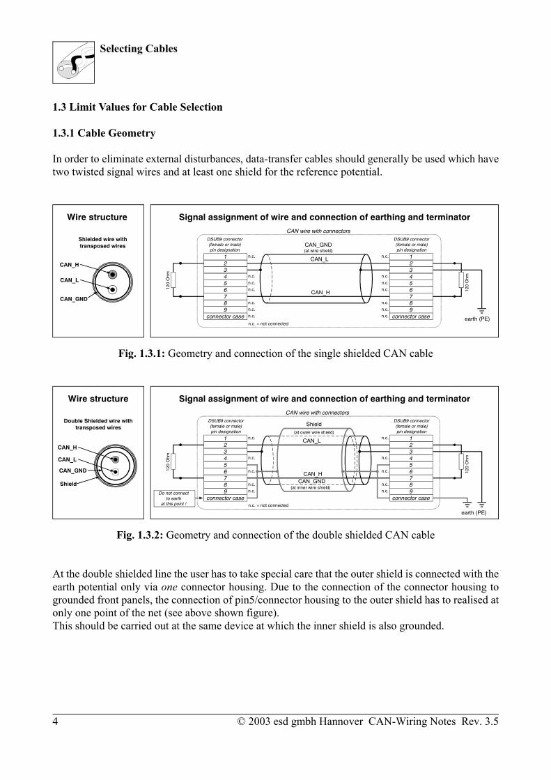
In order to eliminate external disturbances, data-transfer cables should generally be used which havetwo twisted signal wires and at least one shield for the reference potential.
Fig. 1.3.1: Geometry and connection of the single shielded CAN cable
Fig. 1.3.2: Geometry and connection of the double shielded CAN cable
At the double shielded line the user has to take special care that the outer shield is connected with theearth potential only via one connector housing. Due to the connection of the connector housing togrounded front panels, the connection of pin5/connector housing to the outer shield has to realised atonly one point of the net (see above shown figure).This should be carried out at the same device at which the inner shield is also grounded.

Selecting Cables
© 2003 esd gmbh Hannover CAN-Wiring Notes Rev. 3.5 5
1.3.2 Effective Resistance of the Cable
The ISO/DIS 11898 has the following recommendations for the DC voltage parameters, the terminatingimpedances and approximate values for the bit rate:
Bus lengthCable 1*)
Terminatingimpedance
Maximum bitrateResistivity per
meter Cross section of line
0...40 m 70 m /m 0.25 mm², 0.34 mm²AWG23, AWG22 124 / 1% 1 Mbit/s
at 40 m
40 m ... 300 m < 60 m /m 0.34 mm²... 0.6 mm²AWG22, AWG20
127 / 1%2*)
> 500 kbit/sat 100 m
300 m ... 600 m < 40 m /m 0.5 mm², 0.6 mm² AWG20 127 / 1%2*)
> 100 kbit/sat 500 m
600 m ...1 km < 26 m /m 0.75 mm², 0.8 mm²AWG18
127 / 1%2*)
> 50 kbit/sat 1 km
1*) Recommendation for AC parameters of the cable: - 120 characteristic impedance- 5 ns/m delay time
2*) It order to minimize the voltage losses caused by the effective resistance of the cable, a larger value for theterminating impedance (such as 150 ...300 , disregarding the norm ISO/DIS 11898, which here provides '118
< RT < 130 ') might be helpful for longer cables.
Table 1.3.1: Recommended DC voltage parameters depending on line length
1.3.3 Effective Resistance of the DSUB-Connectors
When determining the voltage loss of the cable, the transfer resistance of the connectors have to beconsidered in addition to the cable resistance. According to manufacturer specifications, the volumeresistances of e.g. DSUB-connectors are between 2.5 m and 10 m per contact, i.e. that the effectiveresistance increases by 5 m to 20 m with every plug.
Selecting Cables
© 2003 esd gmbh Hannover CAN-Wiring Notes Rev. 3.56
1.3.4 Examples for Suitable Types of Cable
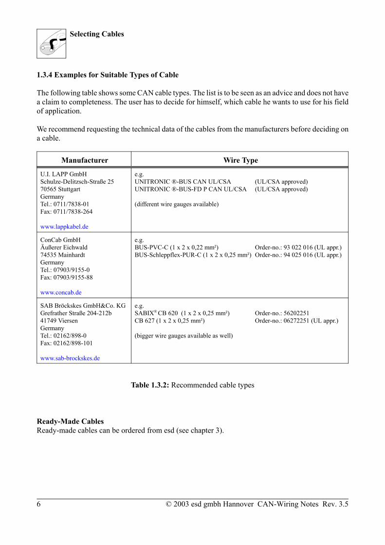
The following table shows some CAN cable types. The list is to be seen as an advice and does not havea claim to completeness. The user has to decide for himself, which cable he wants to use for his fieldof application.
We recommend requesting the technical data of the cables from the manufacturers before deciding ona cable.
Manufacturer Wire Type
U.I. LAPP GmbHSchulze-Delitzsch-Straße 2570565 StuttgartGermanyTel.: 0711/7838-01Fax: 0711/7838-264
www.lappkabel.de
e.g.UNITRONIC ®-BUS CAN UL/CSA (UL/CSA approved)UNITRONIC ®-BUS-FD P CAN UL/CSA (UL/CSA approved)
(different wire gauges available)
ConCab GmbHÄußerer Eichwald74535 MainhardtGermanyTel.: 07903/9155-0Fax: 07903/9155-88
www.concab.de
e.g.BUS-PVC-C (1 x 2 x 0,22 mm²) Order-no.: 93 022 016 (UL appr.)BUS-Schleppflex-PUR-C (1 x 2 x 0,25 mm²) Order-no.: 94 025 016 (UL appr.)
SAB Bröckskes GmbH&Co. KGGrefrather Straße 204-212b41749 ViersenGermanyTel.: 02162/898-0Fax: 02162/898-101
www.sab-brockskes.de
e.g.SABIX® CB 620 (1 x 2 x 0,25 mm²) Order-no.: 56202251CB 627 (1 x 2 x 0,25 mm²) Order-no.: 06272251 (UL appr.)
(bigger wire gauges available as well)
Table 1.3.2: Recommended cable types
Ready-Made CablesReady-made cables can be ordered from esd (see chapter 3).
Selecting Cables
© 2003 esd gmbh Hannover CAN-Wiring Notes Rev. 3.5 7
1.4 Bit Rate Depending on the Cable Lengths
1.4.1 CiA Recommendation for Bit Timing (07/1995)
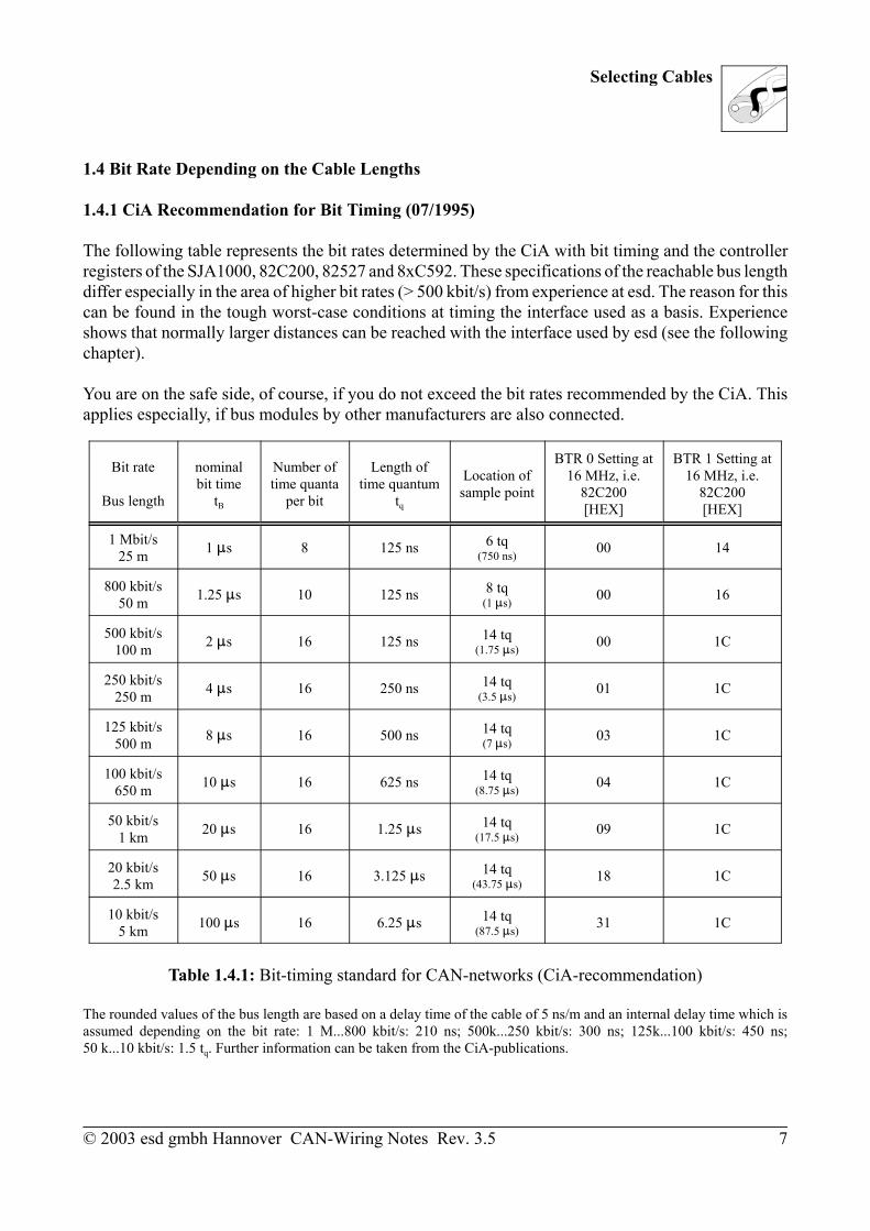
The following table represents the bit rates determined by the CiA with bit timing and the controllerregisters of the SJA1000, 82C200, 82527 and 8xC592. These specifications of the reachable bus lengthdiffer especially in the area of higher bit rates (> 500 kbit/s) from experience at esd. The reason for thiscan be found in the tough worst-case conditions at timing the interface used as a basis. Experienceshows that normally larger distances can be reached with the interface used by esd (see the followingchapter).
You are on the safe side, of course, if you do not exceed the bit rates recommended by the CiA. Thisapplies especially, if bus modules by other manufacturers are also connected.
Bit rate
Bus length
nominalbit time
tB
Number oftime quanta
per bit
Length oftime quantum
tq
Location ofsample point
BTR 0 Setting at16 MHz, i.e.
82C200[HEX]
BTR 1 Setting at16 MHz, i.e.
82C200[HEX]
1 Mbit/s25 m 1 s 8 125 ns 6 tq
(750 ns) 00 14
800 kbit/s50 m 1.25 s 10 125 ns 8 tq
(1 s) 00 16
500 kbit/s100 m 2 s 16 125 ns 14 tq
(1.75 s) 00 1C
250 kbit/s250 m 4 s 16 250 ns 14 tq
(3.5 s) 01 1C
125 kbit/s500 m 8 s 16 500 ns 14 tq
(7 s) 03 1C
100 kbit/s650 m 10 s 16 625 ns 14 tq
(8.75 s) 04 1C
50 kbit/s1 km 20 s 16 1.25 s 14 tq
(17.5 s) 09 1C
20 kbit/s2.5 km 50 s 16 3.125 s 14 tq
(43.75 s) 18 1C
10 kbit/s5 km 100 s 16 6.25 s 14 tq
(87.5 s) 31 1C
Table 1.4.1: Bit-timing standard for CAN-networks (CiA-recommendation)
The rounded values of the bus length are based on a delay time of the cable of 5 ns/m and an internal delay time which isassumed depending on the bit rate: 1 M...800 kbit/s: 210 ns; 500k...250 kbit/s: 300 ns; 125k...100 kbit/s: 450 ns;50 k...10 kbit/s: 1.5 tq. Further information can be taken from the CiA-publications.

Selecting Cables
© 2003 esd gmbh Hannover CAN-Wiring Notes Rev. 3.58
1.4.2 Reachable Line Lengths Via the esd-CAN-Interface
The line length which can be reached by means of the esd-CAN-interface can be determined by meansof the following equations:
tx / cable delaylMAX = -------------------- (tx = residual delay tSAMPLING - tDELAY) 2
tS1 - 2(trxdel + ttxdel + 2topto)lMAX = -------------------------------- 2cable delay
withtS1 = T0Tbrp(Tseg1 - Tsjw + 1) (tS1 = sampling point )
T0 = 2/16 MHz = 125 ns (for SJA1000 and 8xC592)
Tbrp = BTR0x + 1 (BTR0x = contents of register BTR0 of the CAN-controllermasked by $3F (-> bits 6...0 of register BTR0))
Tseg1 = BTR1x + 1 (BTR1x = contents of register BTR1 of the CAN-controllermasked by $0F (-> bits 3...0 of register BTR1))
Tsjw = sjw + 1 (sampling point jump width; sjw = contents of register BTR1 masked by $C0(-> bits 7 and 6 of register BTR1), value range 0..3)
trxdel = max. 62 ns (delay of the CAN-controller) 50 ns (experimental value)
ttxdel = max. 40 ns (Tx) (delays of CAN-transceiver 82C250)max. 80 ns (Rx) 30 ns (typical delay in connection with HCPL710x)
topto = max. 40 ns (Delays of optocoupler HCPL710x) typ. 28 ns 15 ns (typical delays in connection with 82C250)
Cable delay = 5.5 ns/m (typical value for twisted pair (effective length), manufacturerspecifications, see also CiA (previous table 1.4.2))
Therefore, for CAN-controllers SJA1000, 82527 and 8xC592 the following equation results (at a cabledelay of 5.5 ns/m):
[125ns (BTR0x + 1){(BTR1x + 1)-(sjw + 1) + 1}] - [2(trxdel + ttxdel + 2topto)]lMAX = ----------------------------------------------------------------------------- 11ns/m(all times in ns)

Selecting Cables
© 2003 esd gmbh Hannover CAN-Wiring Notes Rev. 3.5 9
The following table represents typically reachable line lengths and the minimum reachable line lengthsfor some bit rates.
The typically reachable line lengths correspond to experience by esd and have been corroborated bymeasurements. esd-CAN-units are standardly tested and checked on keeping to the specified values for1 Mbit/s.The minimum reachable line lengths have been determined from manufacturer specifications for worst-case delays. These line lengths could not be corroborated by measurements, because the delays of thecomponents are normally much better than stated in the worst-case specifications.
Significant changes in the delays caused by temperature can be ruled out. The large dispersions in thedelays are generally caused by production tolerances of the components rather than by temperature.
Please note that a network with terminating impedances forms the basis of these specifications! Eachimpedance disturbance in the line (such as longer dead-end feeders) can cause a reduction of thereachable line length!
typical values of thereachable
line length lmax[m] 1*)
minimum reachableline length lmin
[m] 2*)
bit rate[kbit/s]
8xC592, orSJA1000 registerBTR0[HEX]
BTR1[HEX]
375980
130180270420570710
100014002000360054007300
204265
110160250400550700980
14002000360054007300
1000800
666.6500
333.3250166125100
66.650
33.320
12.510
00000000010102034345474B535F67
1416181C181C1C1C2F2F2F2F2F2F2F
1*) Delays: 2*) Delays:trxdel = 50 ns trxdel = 62 nsttxdel = 30 ns ttxdel = 60 nstopto = 15 ns topto = 40 ns TDEL = 110 ns TDEL = 202 ns
Table 1.4.2: Reachable bit rates depending on the line lengths when using the esd-CAN-interface
Wiring the Devices
© 2003 esd gmbh Hannover CAN-Wiring Notes Rev. 3.510
l < 0,3 m
CAN_L
CAN_GND
CAN_H
PE
l < 0,3 m
CAN-CBM-AI4
CAN-CBM-COM1
CAN-CBM-DIO8
l < 0,3 ml < 0,3 ml < 0,3 m
Female Connector
Male Connector
e.g.CAN-SPS InterfaceCSC595/2orCAN-PC Board
Terminator
Male Terminator(Order-no.: C.1302.01)
Connecting CAN_GND toProtective Conductor PE
Terminatorwith PE Connector
Female Terminator(Order-no.: C.1301.01)
T-ConnectorC.1311.03
CAN-CableOrder-no.: C.1323.03
Net 2
Net 1 e.g. PCI/405,CAN-USB,
VME-CAN2, etc.
CAN-CableOrder-no.: C.1323.03
CAN-CableOrder-no.: C.1323.03
T-ConnectorC.1311.03
T-ConnectorC.1311.03
T-ConnectorC.1311.03
CAN-Board
T-ConnectorOrder-no.: C.1311.03
2. Wiring the Devices
2.1 Wiring and Connection
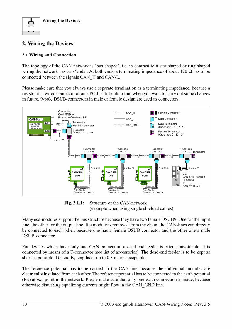
The topology of the CAN-network is ‘bus-shaped’, i.e. in contrast to a star-shaped or ring-shapedwiring the network has two ‘ends’. At both ends, a terminating impedance of about 120 has to beconnected between the signals CAN_H and CAN-L.
Please make sure that you always use a separate termination as a terminating impedance, because aresistor in a wired connector or on a PCB is difficult to find when you want to carry out some changesin future. 9-pole DSUB-connectors in male or female design are used as connectors.
Fig. 2.1.1: Structure of the CAN-network(example when using single shielded cables)
Many esd-modules support the bus structure because they have two female DSUB9: One for the inputline, the other for the output line. If a module is removed from the chain, the CAN-lines can directlybe connected to each other, because one has a female DSUB-connector and the other one a maleDSUB-connector.
For devices which have only one CAN-connection a dead-end feeder is often unavoidable. It isconnected by means of a T-connector (see list of accessories). The dead-end feeder is to be kept asshort as possible! Generally, lengths of up to 0.3 m are acceptable.
The reference potential has to be carried in the CAN-line, because the individual modules areelectrically insulated from each other. The reference potential has to be connected to the earth potential(PE) at one point in the network. Please make sure that only one earth connection is made, becauseotherwise disturbing equalizing currents might flow in the CAN_GND line.
Wiring the Devices
© 2003 esd gmbh Hannover CAN-Wiring Notes Rev. 3.5 11
If a CAN-participant without an electrically insulated interface is connected, it acts as an earthconnection. Therefore, only a maximum of one participant without electrically insulated interfaceshould be connected!
Nearly all esd-CAN-products have an electrically insulated interface. If a module is not electricallyinsulated, this fact will be especially mentioned in the manual of the module.
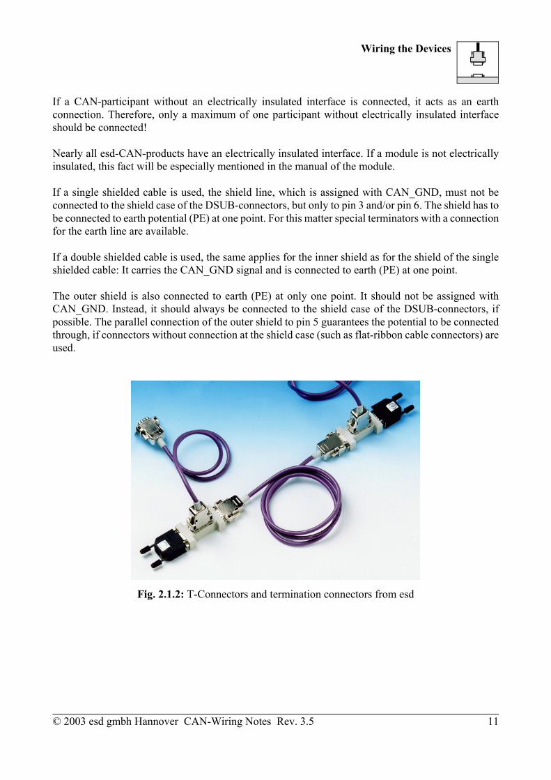
If a single shielded cable is used, the shield line, which is assigned with CAN_GND, must not beconnected to the shield case of the DSUB-connectors, but only to pin 3 and/or pin 6. The shield has tobe connected to earth potential (PE) at one point. For this matter special terminators with a connectionfor the earth line are available.
If a double shielded cable is used, the same applies for the inner shield as for the shield of the singleshielded cable: It carries the CAN_GND signal and is connected to earth (PE) at one point.
The outer shield is also connected to earth (PE) at only one point. It should not be assigned withCAN_GND. Instead, it should always be connected to the shield case of the DSUB-connectors, ifpossible. The parallel connection of the outer shield to pin 5 guarantees the potential to be connectedthrough, if connectors without connection at the shield case (such as flat-ribbon cable connectors) areused.
Fig. 2.1.2: T-Connectors and termination connectors from esd
Wiring the Devices
© 2003 esd gmbh Hannover CAN-Wiring Notes Rev. 3.512
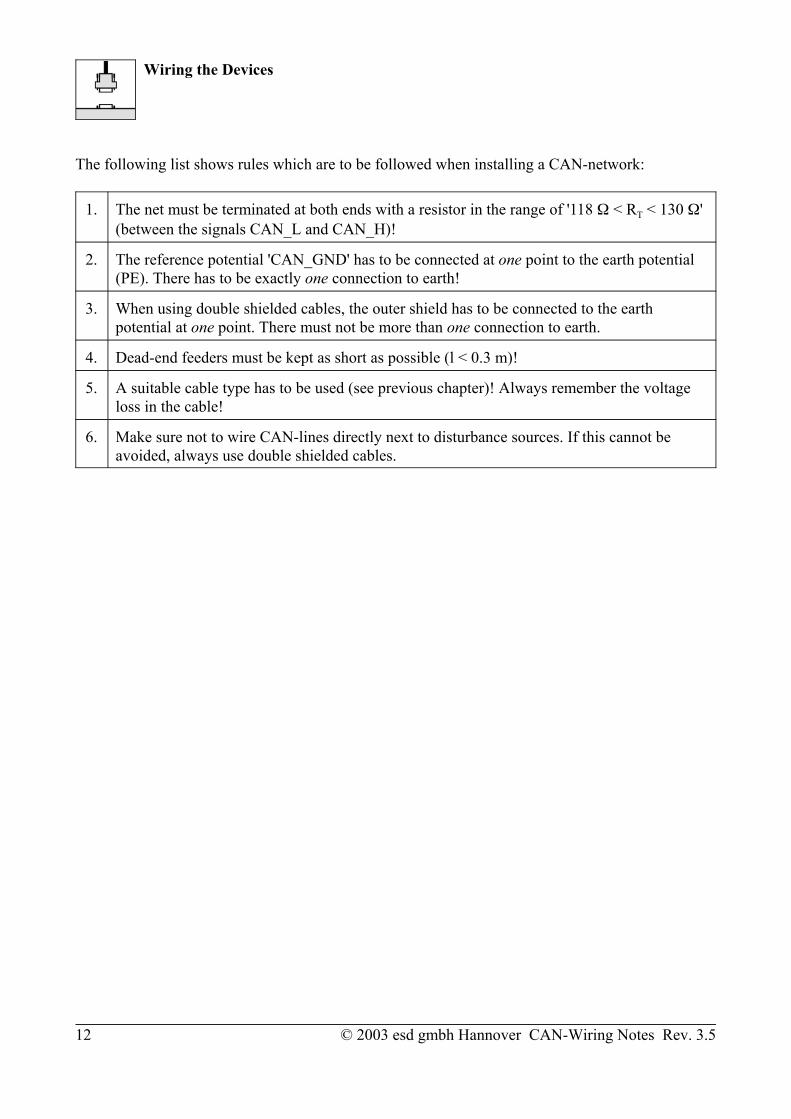
The following list shows rules which are to be followed when installing a CAN-network:
1. The net must be terminated at both ends with a resistor in the range of '118 < RT < 130 '(between the signals CAN_L and CAN_H)!
2. The reference potential 'CAN_GND' has to be connected at one point to the earth potential(PE). There has to be exactly one connection to earth!
3. When using double shielded cables, the outer shield has to be connected to the earthpotential at one point. There must not be more than one connection to earth.
4. Dead-end feeders must be kept as short as possible (l < 0.3 m)!
5. A suitable cable type has to be used (see previous chapter)! Always remember the voltageloss in the cable!
6. Make sure not to wire CAN-lines directly next to disturbance sources. If this cannot beavoided, always use double shielded cables.

Wiring the Devices
© 2003 esd gmbh Hannover CAN-Wiring Notes Rev. 3.5 13
2.2 Connecting the 9-Pole DSUB-Connectors
The following figure represents the assignment of a 9-pole DSUB-connector (male) with the CAN-signals in accordance with the guidelines of the CiA DRP303-1 from 12.12.2001. The CAN-modulesand boards by esd normally only assign the signals CAN_H, CAN_L and CAN_GND. Therefore, theother signals are generally not assigned in connecting cables supplied by esd.
Pin Location:
Pin Assignment:
Signal Pin Signal
1 reserved(GND) 6
2 CAN_LCAN_H 7
3 CAN_GNDreserved 8
4 reserved(CAN_V+) 9
5 (CAN_SHLD) 9-pole DSUB-connector
CAN_L, CAN_H CAN-signal lines
CAN_GND reference potential of the local CAN-physical layer. (Here the shield has to be connected or, when using double shielded cables, the inner shield has to be connected.)
(GND) optional GND and reference potential of CAN_V+ (Is assigned with CAN_GND on esd-boards.)
(CAN_SHLD) CAN-shieldCAN-SHLD has to be connected to the outer shield and the shield case of the DSUB-connector whenusing double shielded cables. In addition, the shield has to be connected to pin 5 in order to guaranteethat the potential is connected through when using connectors without shield connection.
(CAN_V+) optional, to be externally fed supply voltage of the CAN-interface (+7V< V+< +13V).The voltage feed via the CAN is not required by most of the esd-boards. If the voltage feed is required,however, make sure to route the line outside of the first shield of the signal lines and to use asufficiently strong line in order to keep the voltage loss low.

Wiring the Devices
© 2003 esd gmbh Hannover CAN-Wiring Notes Rev. 3.514
12345
2.2 Connecting the 5-Pole Combicon-Style-Connectors
Pin-Assignment: Signals:
Pin Signal
5 (CAN_V+)
4 CAN_H
3 (CAN_SHLD)
2 CAN_L
1 CAN_GND
Signal Terms:see DSUB connector at previous page
Pin assignment of an adapter cable 5-pole Combicon to 9-pole DSUB (without power connection):
The 9-pin DSUBconnector isassigned inaccordance withCiA DRP303-1.

Accessories
© 2003 esd gmbh Hannover CAN-Wiring Notes Rev. 3.5 15
3. Available Accessories
Type Characteristics Order No.
CAN-Termination Terminating impedance in 9-pole DSUB-connector(female) with a 4.8 mm fast-on plug to earth the referencepotential CAN_GND
C.1301.01
Terminating impedance in 9-pole DSUB-connector(male) with a 4.8 mm fast-on plug to earth the referencepotential CAN_GND
C.1302.01
CAN-T-Connector 2 x female DSUB9, 1 x DSUB9-male C.1311.03
CAN-cable-SBCAN-cable with two DSUB-connectors (Grade 3 quality),1 x female contact, 1 x male contact, dimension 2 x0.22 mm²
xxx... three-digit specification of line length indecimeters
Following prevered cable length are available on stock:0.3 m0.5 m1.0 m2.0 m2.5 m3.0 m4.0 m5.0 m10 m
Other lenght are available on request.
C.1322.xxx
CAN-CBM-cable CAN-cable with one DSUB-connector (male contacts,Grade 3 quality) and one open end, e.g. to connect aCombicon-style connector, dimension 2 x 0.22 mm²,lenght 0.3 m
C.1323.03
CAN-FB-cable-SB CAN-flat-ribbon cable with two DSUB-connectors(Grade 3 quality), 1 x female contact, 1 x male contact,length 0.1 m
C.1323.01


![5. Wiring Diagram - Subaru Forester. Wiring Diagram A: POWER SUPPLY ROUTING SU01-04A 12 6-3 [D5A0] WIRING DIAGRAM 5. Wiring Diagram SU01-04B 13 WIRING DIAGRAM [D5A0] 6-3 5. Wiring](https://img.pdfslide.us/doc/110x75/5aa205fe7f8b9a1f6d8cac3f/5-wiring-diagram-subaru-wiring-diagram-a-power-supply-routing-su01-04a-12.jpg)