Embed Size (px)
Citation preview
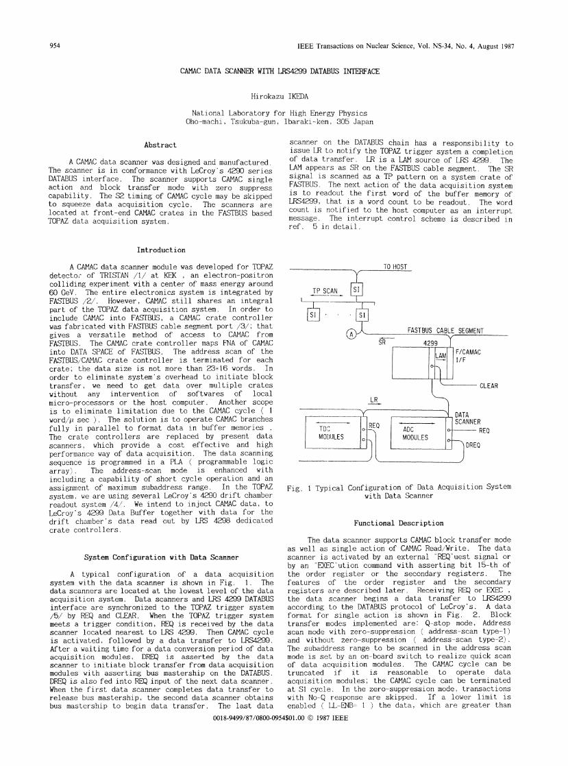
IEEE Transactions on Nuclear Science, Vol. NS-34, No. 4, August 1987
CAMAC DATA SCANNER WITH LRS4299 DATABUS INTERFACE
Hirokazu IKEDA
National Laboratory for High Energy PhysicsOho--machi, Tsukuba-gun, Ibaraki-ken, 305 Japan
Abstract
A CAMAC data scanner was designed and manufactured.The scanner is in conformance with LeCroy's 4290 seriesDATABUS interface. The scanner supports CAMAC singleaction and block transfer mode with zero suppresscapability. The S2 timing of CAMAC cycle may be skippedto squeeze data acquisition cycle. The scanners arelocated at front-end CAMAC crates in the FASTBUS basedTOPAZ data acquisition system.
scanner on the DATABUS chain has a responsibility toissue LR to notify the TOPAZ trigger system a completionof data transfer. LR is a LAM source of LRS 4299. TheLAM appears as SR on the FASTBUS cable segment. The SRsignal is scanned as a TP pattern on a system crate ofFASTBUS. The next action of the data acquisition systemis to readout the first word of the buffer memory ofLRS4299, that is a word count to be readout. The wordcount is notified to the host computer as an interruptmessage. The interrupt control scheme is described inref. 5 in detail.
Introduction
A CAMAC data scanner module was developed for TOPAZdetector of TRISTAN /I/ at KEK , an electron-positroncolliding experiment with a center of mass energy around60 GeV. The entire electronics system is integrated byFASTBUS 12 However, CAMAC still shares an integralpart of the TOPAZ data acquisition system. In order toinclude CAMAC into FASTBUS, a CAMAC crate controllerwas fabricated with FASTBUS cable segment port /3/; thatgives a versatile method of access to CAMAC fromFASTBUS. The CAMAC crate controller maps FNA of CAMACinto DATA SPACE of FASTBUS. The address scan of theFASTBUS `CAMAC crate controller is terminated for eachcrate; the data size is not more than 23.16 words, Inorder to eliminate system's overhead to initiate blocktransfer, we need to get data over multiple crateswithout any intervention of softwares of localmicro-processors or the host computer. Another scopeis to eliminate limitation due to the CAMAC cycle ( Iword/p sec ). The solution is to operate CAMAC branchesfully in parallel to format data in buffer memories .
The crate controllers are replaced by present datascanners, which provide a cost effective and highperformance way of data acquisition. The data scanningsequence i-s programmed in a PLA ( programmable logicarray). The address- scan mode is enhanced withincluding a capability of short cycle operation and anassignment of maximum subaddress range. In the TOPAZsystem, we are using several LeCroy's 4290 drift chamberreadout system /4,'. We intend to inject CAMAC data, toLeCroy's 4299 Data Buffer together with data for thedrift chamber's data read out by LRS 4298 dedicatedcrate controllers.
System Configuration with Data Scanner
A typical configuration of a data acquisitionsystem with the data scanner is shown in Fig. 1. Thedata scanners are located at the lowest level of the dataacquisition system. Data scanners and LRS 4299 DATABUSinterface are synchronized to the TOPAZ trigger system/5/ by REQ and CLEAR. When the TOPAZ trigger systemmeets a trigger condition, REQ is received by the datascanner located nearest to LRS 4299. Then CAMAC cycleis activated, followed by a data transfer to LRS4299.After a waiting time for a data conversion period of dataacquisition modules, DREQ is asserted by the datascanner to initiate block transfer from data acquisitionmodules with asserting bus mastership on the DATABUS.DREQ is also fed into REQ input of the next data scanner.When the first data scanner completes data transfer torelease bus mastership, the second data scanner obtainsbus mastership to begin data transfer. The last data
SI
Fig. 1 Typical Configuration of Data Acquisition Systemwith Data Scanner
Functional Description
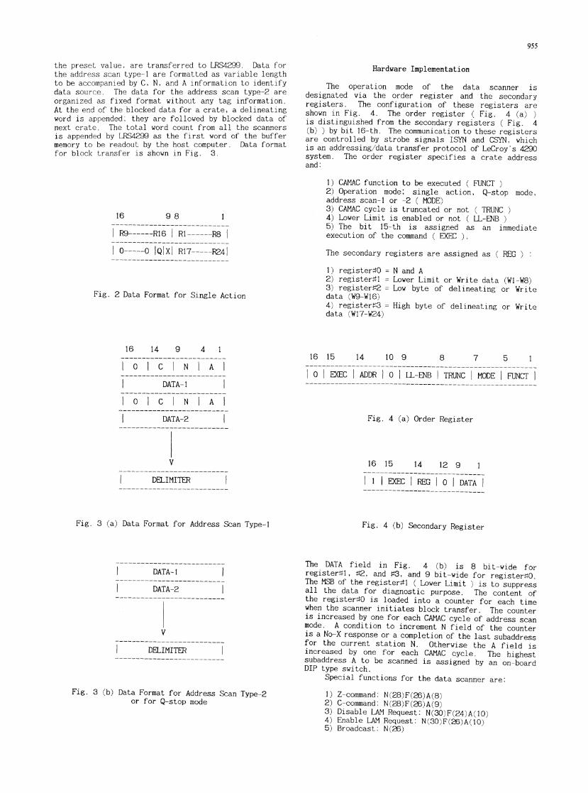
The data scanner supports CAMAC block transfer modeas well as single action of CAMAC Read/Write. The datascanner is activated by an external REQ"uest signal orby an 'EXECution command with asserting bit 15-th ofthe order register or the secondary registers. Thefeatures of the order register and the secondaryregisters are described later. Receiving REQ or EXEC Ethe data scanner begins a data transfer to LRS4299according to the DATABUS protocol of LeCroy's. A dataformat for single action is shown in Fig. 2. Blocktransfer modes implemented are: Q-stop mode, Addressscan mode with zero-suppression ( address-scan type-1)and without zero-suppression ( address-scan type-2).The subaddress range to be scanned in the address scanmode is set by an on-board switch to realize quick scanof data acquisition modules. The CAMAC cycle can betruncated if it is reasonable to operate dataacquisition modules; the CAMAC cycle can be terminatedat SI cycle. In the zero suppression mode, transactionswith No-Q response are skipped. If a lower limit isenabled ( LL-ENB- 1 ) the data, which are greater than
0018-9499/87/0800-0954$01.00 © 1987 IEEE
954
955
the preset value, are transferred to LRS4299. Data forthe address scan type-1 are formatted as variable lengthto be accompanied by C, N, and A information to identifydata source. The data for the address scan type-2 areorganized as fixed format without any tag information.At the end of the blocked data for a crate, a delineatingword is appended; they are followed by blocked data ofnext crate. The total word count from all the scannersis appended by LRS4299 as the first word of the buffermemory to be readout by the host computer. Data formatfor block transfer is shown in Fig. 3.
16 9 8
R9------R16 Rl--
0-----0 IQIXI R17-
1~4----R8
.----241
Hardware Implementation
The operation mode of the data scanner isdesignated via the order register and the secondaryregisters. The configuration of these registers areshown in Fig. 4. The order register ( Fig. 4 (a) )is distinguished from the secondary registers ( Fig. 4(b) ) by bit 16-th. The communication to these registersare controlled by strobe signals ISYN and CSYN, whichis an addressing/data transfer protocol of LeCroy's 4290system. The order register specifies a crate addressand:
1) CAMAC function to be executed ( FUNCT2) Operation mode; single action, Q-stop mode,address scan-1 or -2 ( MODE)3) CAMAC cycle is truncated or not ( TRUNC4) Lower Limit is enabled or not ( LL-ENB5) The bit 15-th is assigned as an immediateexecution of the command ( EXEC ).
The secondary registers are assigned as ( REG
Fig. 2 Data Format for Single Action
1) register#O2) registert13) register#2data (W9-W16)4) register#3data (WI7-W24)
N and ALower Limit or Write data (WI-W8)Low byte of delineating or Write
High byte of delineating or Write
16 14 9 4 1
° C N A
DATA-1
° C N A__________________________
DATA-22
V
- DELIMITER
Fig. 3 (a) Data Format for Address Scan Type-I
__________________________
DATA-1
DATA-2
V
DELIMITER
Fig. 3 (b) Data Format for Address Scan Type-2or for Q-stop mode
16 15 14 10 9 8 7 5 1-------------------------------------------------------
10 EXEC I ADDR 0° LL-ENB TRUNC MODE FUNCT-------------------------------------------------------
Fig. 4 (a) Order Register
16 15 14 12 9 1______________________
I 1 EXEC PREG 0 DATA
Fig. 4 (b) Secondary Register
The DATA field in Fig. 4 (b) is 8 bit-wide forregister#1, ,2, and #3, and 9 bit-wide for registerO.The MSB of the register#1 ( Lower Limit ) is to suppressall the data for diagnostic purpose. The content ofthe register#O is loaded into a counter for each timewhen the scanner initiates block transfer. The counteris increased by one for each CAMAC cycle of address scanmode. A condition to increment N field of the counteris a No-X response or a completion of the last subaddressfor the current station N. Otherwise the A field isincreased by one for each CAMAC cycle. The highestsubaddress A to be scanned is assigned by an on-boardDIP type switch.
Special functions for the data scanner are:
1) Z-command: N(28)F(26)A(8)2) C-command: N(28)F(26)A(9)3) Disable LAM Request: N(30)F(24)A(10)4) Enable LAM Request: N(30)F(26)A(lO)5) Broadcast: N(26)
956
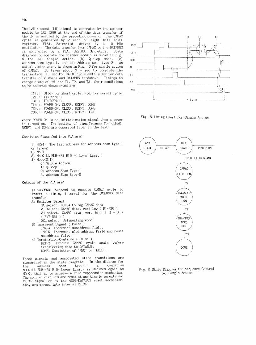
The LAM request (LR) signal is generated by the scannermodule to LRS 4299 at the end of the data transfer ifthe LR is enabled by the preceding command. The CAMACcycle is generated by 2 each of eight bits shiftregister F164, Fairchild, driven by a 10 MHzoscillator The data transfer from CAMAC to the DATABUSis controlled by a PLA, 82,slOO, Signetics. Statediagrams to operate the scanner module is shown in Fig.5 for (a' Single Action, (b) Q-stop mode, (c)Address-scan type 1, and (d) Address scan type 2. Anactual timing chart is shown in Fig. 6 for single actionof CAMAC. It takes about 3 p sec to complete thetransaction; I p sec for CAMAC cycle and 2 p sec for datatransfer of 2 words and DATABUS handshake. Timings tochange state of PAL are TI, T2, and T3; their conditionsto be asserted/deasserted are:
TI (T2T31Ti iT2tT3
u''u).udd)d
SI (d) for short cycle, N (d) for normal cycleT1*ISYN u)T2+JISYN (u)POWER--ON, CLEAR, RETRY, DONEPOWER-ON, CLEAR, REFRY, DONEPOWER-ON, CLEAR, REFRY, DONE
where POWER-ON is an initialization signal when a poweris turned on. The actions of significance for CLEAR,RETRY, and DONE are described later in the text.
Condition flags fed into PLA are:
T2 T3
ISYN L
CSYN
III Q
N
Si
S2
DONE
3iisec
Fig. 6 Timing Chart for Single Action
N(24): The last address for address scan type-1type-2No-XNo-Q+LL-ENB*(Rl-Rl6 =< Lower Limit )Mode<0:1>
0: Single Action1: Q-Stop2: Address Scan Type- 13: Address Scan type-2
Outputs of the PLA are:
1) SUSPEND: Suspend to execute CAMAC cycle to
insert a timing interval for the DATABUS datatransfer.2) Register Select
NA select: C,N,A to tag CAMAC data.WL select: CAMAC data, word low ( Rl-R16WH select: CAMAC data, word high ( Q + X +
( R17-R24 ) )DEL select: Delineating word
3) Increment Signal ( Pulse )INX--A: Increment subaddress field.INX-N: Increment slot address field and resetsubaddress filed.
4) Termination/Continue ( PulseREFRY: Execute CAMAC cycle again beforetransferring data to DATABUS.DONE: Completion of "REQ' or "EXEC".
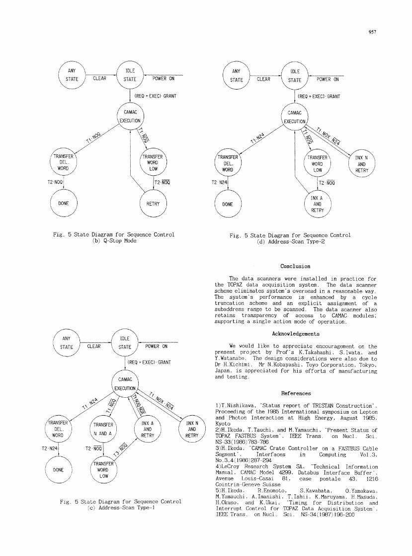
These signals and associated state transitions are
summarized in the state diagrams. In the diagram for
the address scan type-1, a condition
NO-Q+LL-ENB* 'R1-R16<Lower Limit) is defined again as
NO-Q; that is to achieve a zero-zuppression mechanism.
The control circuits are reset at any time by an external
CLEAR signal or by the 4299/DATABUS reset mechanism;
they are merged into internal CLEAR.
Fig. 5 State Diagram for Sequence Control
(a) Single Action
I)or2)3)4)
POWER ON
--J-L..
C_.
.-J-L-
957
Fig. 5 State Diagram for Sequence Control(b) Q-Stop Mode
Fig. 5 State Diagram for Sequence Control(c) Address-Scan Type-1
Fig. 5 State Diagram for Sequence Control(d) Address-Scan Type-2
Conclusion
The data scanners were installed in practice forthe TOPAZ data acquisition system. The data scannerscheme eliminates system's overilead in a reasonable way.The system's performance is enhanced by a cycletruncation scheme and an explicit assignment of asubaddress range to be scanned. The data scanner alsoretains transparency of access to CAMAC modules;supporting a single action mode of operation.
Acknowledgements
We would like to appreciate encouragement on thepresent project by Prof's K.Takahashi, S.Iwata, andY.Watanabe. The design considerations were also due toDr H.Kichimi. Mr N.Kobayashi, Toyo Corporation, Tokyo,Japan, is appreciated for his efforts of manufacturingand testing.
References
I)T.Nishikawa, "Status report of TRISTAN Construction",Proceeding of the 1985 International symposium on Leptonand Photon Interaction at High Energy, August 1985,Kyoto2)H.Ikeda, T.Tauchi, and M.Yamauchi, 'Present Status ofTOPAZ FASTBUS System", IEEE Trans. on Nucl. Sci.NS-33 198 )783-7863)H.Ikeda, 'CAMAC Crate Controller on a FASTBUS CableSegment", Interfaces in Computing Vol.3.No.3,4 1986) 287-2944)LeCroy Research System SA, 'Technical InformationManual, CAMAC Model 4299, Databus Interface Buffer",Avenue Louis-Casai 81, case postale 43, 1216Cointrin-Geneve Suisse5)H.Ikeda, R.Enomoto, S.Kawabata, O.Yamakawa,M.Yamauchi, A. Imanishi, T.Ishii, K.Maruyama, H.Masuda,H.Okuno, and K.Ukai, "Timing for Distribution andInterrupt Control for TOPAZ Data Acquisition System'",IEEE Trans. on Nucl. Sci. NS-34(1987)196-200