Embed Size (px)
Citation preview
August 1972
Labor für Elektronik und Meßtechnik
KFK 1641
CAMAC - Specification of Amplitude Analogue SignalsExtension of the Specification of Amplitude Analogue Signals
tEUB-5JOO ~.1972-J-}-al""ldCQrnmeRts-of-theE-SON-E-W0fkiFlg-Gr-otJp
K. Tradowsky

Als Manuskript vervielfältigt
Für diesen Bericht behaiten wir uns alle Rechte vor
GESEllSCHAFT FüR KERNFORSCHUNG M.B.H.
KARlSRUHE
August 1972
KERNFORSCHUNGSZENTRUM KARLSRUHE
Labor für Elektronik und Meßtechnik
CAMAC - Specification of Amplitude Analogue Signals
KFK 1641
Extension of the Specification of Amplitude Analogue Signals (EUR 5100 [1972])
and Comments of the ESONE Working Group
K. Tradowsky*
* Editor, Chairman of the ESONE Working Group on Analogue Signals
Gesellschaft für Kernforschung m.b.H; Karlsruhe

Abstract
This report is written as an extension of the Specification of Amplitude Analogue Signalspublished as Euratom Report EUR 5100 and relates to signals which are recommended for use byCAMAC cornpatible units. It specifies amplitude analogue signals whose risetimes are shorterthan 50 ns (corresponding to a 3 dB upper cutoff frequency of approximately 7 MHz). A terminated 50 n system with 0 to - 1 volt working range is recommended.The technical part ofthis recommendation has been agreed upon by the US AEC NIM Committee.
In Part B comments of the ESONE Working Group are given for explanation.
Zusammenfassung
Dieser Bericht enthält die Erweiterung der Spezifikation der Amplituden-analogen Signale, die alsEuratom-Bericht EUR 5100 veröffentlicht wurde, und bezieht sich auf Signale, die für CAMACkompatible Einheiten empfohlen werden. Er spezifiziert Amplituden-analoge Signale mitAnstiegszeiten kürzer als 50 ns (das entspricht einer oberen 3-dB-Grenzfrequenz von ungefähr7 MHz). Es wird ein abgeschlossenes 50-n-System mit einem Arbeitsbereich von 0 bis - 1 Vempfohlen. Das US AEC NIM Committee hat dem technischen Teil dieser Empfehlung zugestimmt.
In Teil B des Berichtes wird die Spezifikation von der ESONE Working Group kommentiert underläutert,
Contents
Part A CAMAC: A Modular Instrumentation System for Data Handling. Specification ofAmplitude Analogue Signals. Extension of the Specification of Aiuplitude AnalogueSignals (EUR 5100).
(Approved Text, ESONE Working Group on Analogue Signals, Harwell July Lst, 1972)
Part B Comments of the ESONE Working Group on Analogue Signals to the Extension of theSpecification of Amplitude Analogue Signals (EUR 5100 [1972])
(0. Fromhein, K. Tradowsky [Chairman])
Part A
CAMAC
A MODULAR INSTRUMENTATION SYSTEM FOR DATA HANDLING
Specification of Amplitude Analogue Signals
Extension of the Specificationof Amplitude Analogue Signals (EUR 5100)
ABSTRACT
This document is written as an extension of the Specification of Amplitude Analogue Signalspublished as Euratom Report EUR 5100 and relates to signals which are recommended for useby CAMAC compatibie units, It specifies amplitude anaiogue signals whose rise times areshorter than 50 ns (corresponding to a 3 dB upper cutoff frequency of approximately 7 MHz).
--Aterminated-SOnsystem with-Oto - I-volt workingrange.is recommended.
The technical part of this recommendation has been agreed upon by the US ABC NIMCommittee.
Approved TextESONE Working Group on Analogue SignalsHarwellJuly 1st, 1972
1.
2.
3.
3.1.3.1.1.3.1.2.3.1.3.3.1.4.3.1.5.
3.2.3.2.1.3.2.2.3.2.3.3.2.4.
4.
4.1.
4.2.
Tabie i
Contents
lntroduction .
Interpretation of this Document
Specification of Amplitude Analogue Signals
Output Characteristics , ,Output Voltage Range ..Maximum Output Voltage .Output Polarity . . . . .Output ImpedanceOutput Protection . . . . . . . . . . . . . . . . . . . .
Input CharacteristicsInput ImpedanceInput Voltage RangeInput Polarity .Input Protection . . .
Connectors and Cables
Coaxial Connector . . .
Coaxial Cable Impedance
Amplitude Analogue Signals for CAMAC
Page No.
3
3
4
444555
55566
6
6
6
7
Appendix 1
Appendix 2
Related Specifications
The ESONE Committee
8
8
1. INTRODUCTION
The ElJRATOM Report EUR4100e defmes the essential features of the CAMAC system ofinstrumentation. This system is primarily for on-line use with digital controllers or computers.
Representatives of European Research Laboratories, under the auspices of the ESONECommittee (Appendix 2), have agreed to recommend standard analogue signals for usewith theCAMAC system.
This specification 15 published to ensure compatibility between CAMAC units which processanalogue signals.
This specification, as far as technically feasible, applies to the processing of signals whose risetimes (tr )l are shorter than 15 nanoseconds (fc ~ 23 MHz).
This specification may also be used for signals whose rise times (tr) are shorter than or equal to50 nanoseconds (fc ~ 7 MHz).
The technical features of any equipment must meet the outlined specifications only within thedesigned frequency range.
2. INTERPRETATION OF THIS DOCUMENT
This document is the reference text describing and specifying amplitude analogue signals for useby units w11icll conform ta the CA.1V1AC specification EUR 41 OOe (197 2)~ It supersedes therecornmendations in Section 7.3 ofEUR4100e (1969).
Statements which specify mandatory aspects of the standard are written in bold type andblocked in, as here, and are usually accompanied by the word "must",
The werd"should" indicatesarecommended or preferred practice which istobe foliowed unlessthere are sound reasons to the contrary.
The word "may" indicates good practice but leaves freedom of choice to the designer.
In order to claimcompatibility with this specification a signal must comply with themandatory staternents in thisdocument,
All. amplitude analogue signal is one whoseamplitude conveys significant inforrnation. Thisspecification applies both to continuous and to pulse-like electrical signals. In the latter case, the'amplitude may be significant during a portion of the waveform (e.g. as for peak pulse amplitudeanalysis) or throughout the duration of the waveform (e.g. as for pulse shape analysis).
A praetical relationship between the upper 3 db cutoff frequeney (fe) and rise time (t r) of a pulse-likc signal, defincd as
the time interval between the 10 and 90 percentile points, is approximately given by tr • fe ~ 0.34.
3
The standards defined below must be used for analogue signals which are input or outputthrough connectors on the front panel of CAMAC compatible units, or at the back ofCAMAC compatible units above the Dataway, unless there are strong technical reasons tothe contrary.
There may, however, be special circumstances requiring some deviations from this specificationto suit a specific equipment with which the CAMAC compatible unit is closely associated. In suchcases, these deviations are tolerated until further CAMAC and/or IEC specifications are availablefor use.
3. SPECIFICATION OF AMPLITUDE ANALOGUE SIGNALS
This specification, as far as technically feasible, must apply to the processing of signalswhose rise times (tr)l are shorter than 15 ns (fc ~ 23 MHz).
This specification may also be used for signals whose rise times (tr) are shorter than or equal to50 ns(fc ~. 7 MHz).
The specification given below is summarized in Table I.
3.1.
3.1.1.
Output Characteristics
Output Voltage Range
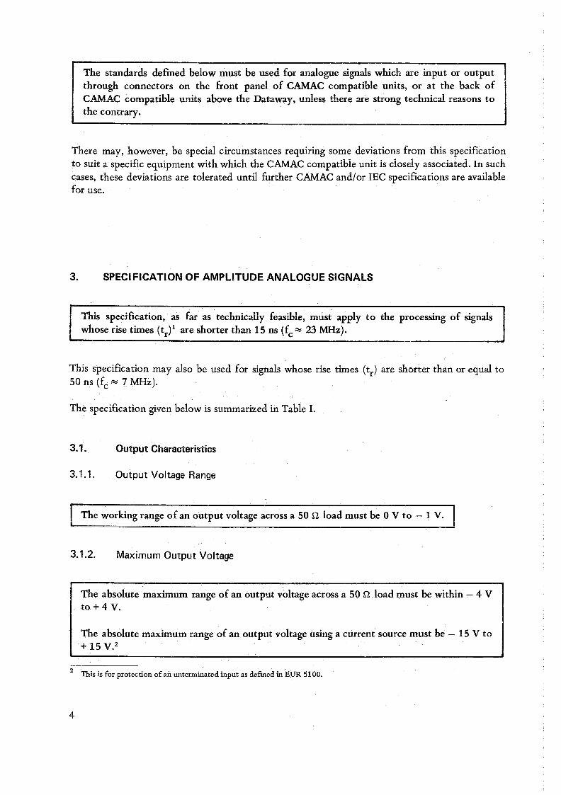
The working range of an output voltage across a 50 Q load must be 0 V to - 1 V.
3.1.2. Maximum Output Voltage
The absolute maximum range of an output voltage across a 50 Q load must be within - 4 Vto+4 V.
The absolute maximum range of an output voltage using a current source must be - 15 V to+ 15 V."
2 This is for proteetion of an unterminated input as defined in BUR 5100.
4
3.1.3. Output Polarity
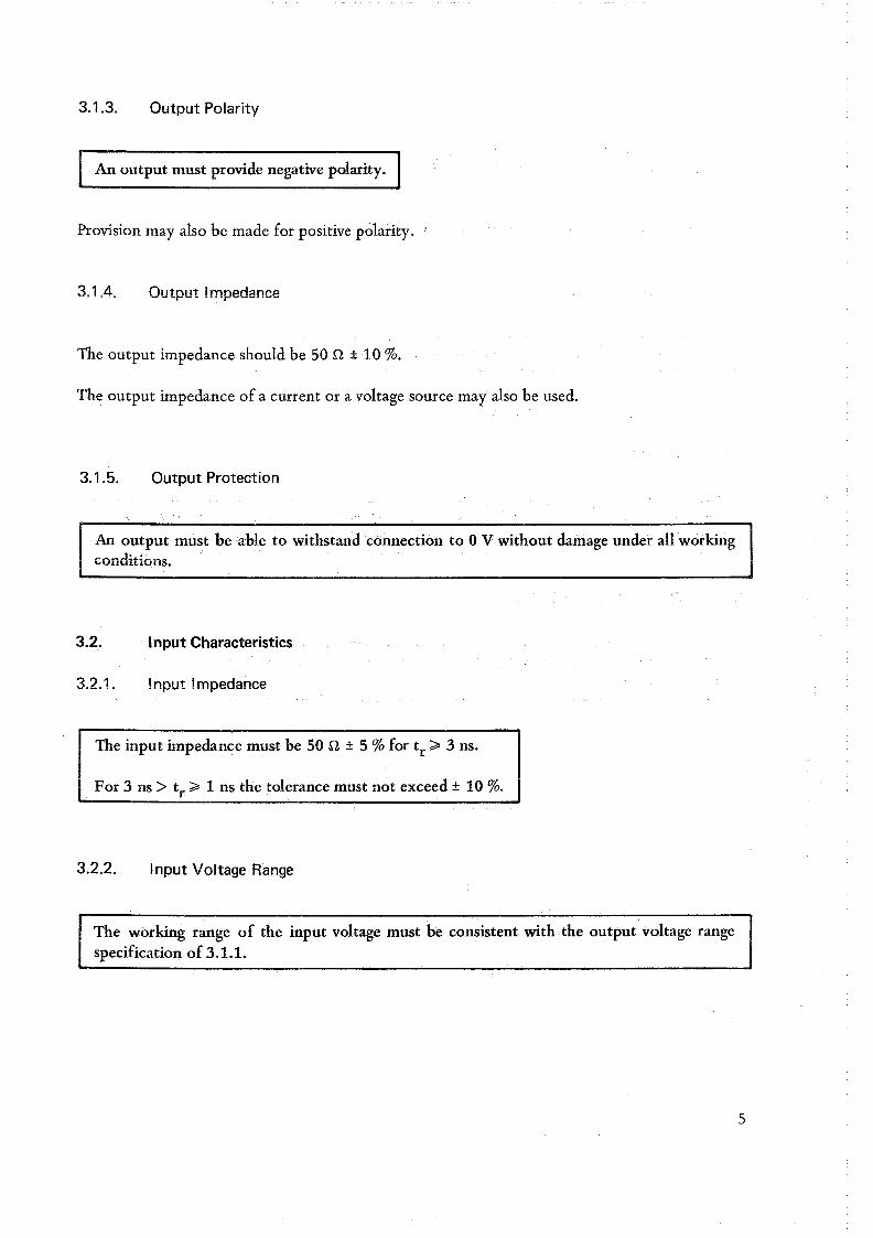
An output must provide negative polarity.
Provision may also be made for positive polarity.
3.1.4. Output !mpedance
The output impedance should be 50 Q ± 10 %.
The output impedance of a current or a voltage source may also be used.
3.1.5. Output Protection
An output must beable towithstandconnection to 0 V without damage under allwörkingLconditions.
3.2.
3.2.1.
Input Characteristics
Input !mpedance
The input impedance must be 50 n ± 5 % for t r ~ 3 ns.
For 3 ns> t r ~ 1 ns the tolerance must not exceed ± 10 %.
3.2.2. Input Voltage Range
The working range of the input voltage must be consistent withthe outpur voltage rangespecification of 3.1.1.
5
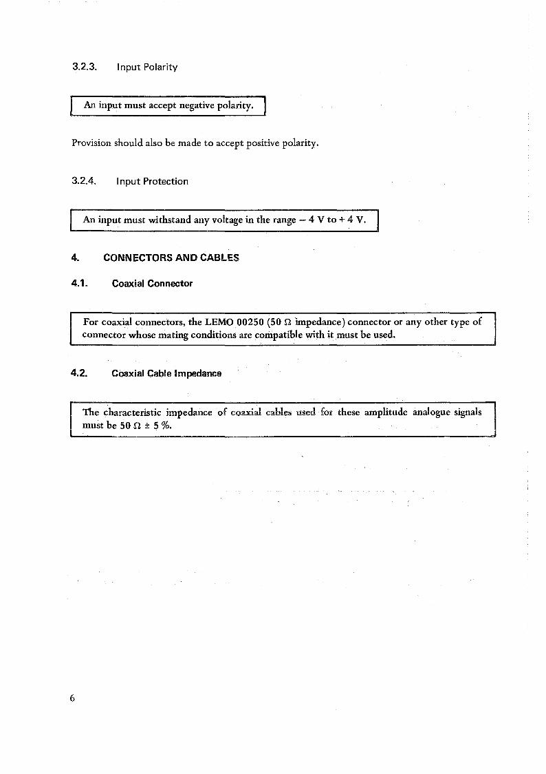
3.2.3. Input Polarity
.An input must accept negative polarity.· IProvision should also be made to accept positive polarity.
3.2.4. Input Protection
.An input must withstand any voltage in the range - 4 V to + 4 V.
4. CONNECTORS AND CABLES
4.1. Coaxial Connector
For coaxial connectors, the LEMO 00250 (50 n impedance) connector or any other type ofconnector whose mating conditions are compatible with it must be used.
4.2. Coaxial Cable Impedance
The characteristic impedance of coaxial cables used for these amplitude analogue signalsmust be 50 n ± 5 %.
6
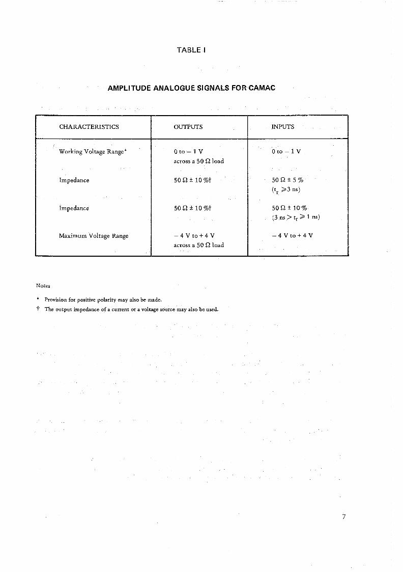
TAßlEI
AMPLITUDE ANALOGUE SIGNALS FORCAMAC
CHARACTERISTICS OUTPUTS INPUTS
Working Voltage Range* oto -1 V o to - 1 V
across a 50 Q load
Impedance 50Q±10%t 50Q ± 5 %
(t r ~3 ns)
Impedance 50Q±10%t 50Q ± 10%
(3 ns > tr ~ 1 ns)
Maximum Voltage Range - 4 V to +4 V - 4 V to+ 4 V
across a 50 Q load
Nofes
* Provision for positive polarity may also be made.
t The output impedance of a current or a voltage source may also be used.
7
Appendix 1
RELATED SPECIFICATIONS
CAMAC: A Modular Instrumentation System for Data Handling. Revised Description andSpecification,
Euratom Report EUR 4100e (1972), Commission of the European Communities, Luxembourg,1972(technically identical with: TID-'25875)
CAMAC: Organisation of Multi-Crate Systems. Specification of the Branch Highway and CAMACCrate Controller Type A.
Euratom Report BUR 4600e, Commission of the European Communities, Luxembourg, 1972(technically identical with: TID-25876)
CAMAC: A Modular Instrumentation System for Data Handling. Specification of AmplitudeAnalogue Signals.
Euratom Report EUR 5100e (1972) (to be published in 1972)
Standard Instrument ModulesReport TID-20893 (Revision 3), United States Atomic Energy Commission, 1969
Appendix 2
THE ESONE COMMllTEE
The Committee comprises representatives from laboratories, institutes and organisations thathave an interest in the compatibility of electronic equipment.
The Comrnittee has a permanent Secretariat. When the Committee is not in session its business ishandled by an Executive Group consisting of the secretary and one representative from each ofC E.R N., Euratom, C.E.A. France, U.K. Nuclear Laboratories, Deutsche Studiengruppe fürNukleare Elektronik, and C.N.E.N. Italy. These representatives are nominated by their respectiveorganisations. The Chairman of the Executive Group is also the Chairman of the ESONECommittee and is chosen annually from the nominated representatives.
A list of member laboratories is given in this Appendix. Further information about currentmembership and nominated representatives on the Committee and Executive Group can beobtained from the Secretary*.
This document is issued with the approval of the Executive Group. Any questions relating to the:.. .•. r. 1- 1 "t 1 1 1·'._ 'I 'i......... .. ._ .., ..Interpretation or trns uocument snoutd be sunrmttea to tne ~ecretary. Any pomts tnat cannot be
c1eared by him will be referred to the Executive Group for resolurion.
8
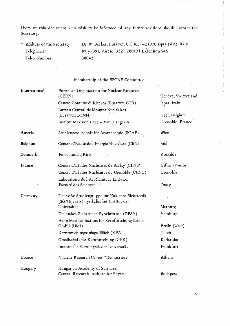
Users of this document who wish to be informed of any future revisions should inform theSecretary.
* Address of the Secretary:
Telephone:
Telex Number:
Dr. W Becker, Euratom C.C.R., 1-21020 Ispra (VA), Italy
Italy (39), Varese (332), 780131 Extension 245.
38042.
Membership of the ESONE Committee
International
Austria
Belgium
Denmark
France
Germ-any
Greece
Hungary
European Organization for Nuclear Research(CERN)
Centro Comune di Ricerca (Euratom CCR)
Bureau Central de Mesures Nucleaires(Euratom BCMN)
Institut Max von Laue ~ PauI Langevin
Studiengesellschaft für Atomenergie (SGAE)
Centre d'Etude de I'Energie Nucleaire (CEN)
Forsögsanläg Risö
Centre d'Etudes Nucleaires de Saciay (CENS)
Centre d'Etudes Nucleaires de Grenoble (CENG)
Laboratoire de l' Accelerateur Lineaire,Faculte des Seiences
(SGNE), c/o Physikalisches Institut derUniversität
Deutsches Elektronen-Synchrotron (DESY)
Hahn-Meitner-Institut für Kernforschung BerlinGmbH (HMI)
Kernforschungsanlage jülich (KFA)
Gesellschaft für Kernforschung (GFK)
Institut für Kernphysik. der Universität
Nuclear Research Center "Democritus"
Hungarian Academy of Sciences,Central Research Institute for Physics
Geneve, Switzerland
Ispra, Italy
Geel, Belgium
Grenoble, France
Wien
Mol
Roskilde
Cif-sur-Yvette
Grenoble
Orsay
Marburg
Hamburg
Berlin (West)
Jülich
Karlsruhe
Frankfurt
Athens
Budapest
9
Italy
Netherlands
Poland
Sweden
Switzerland
United Kingdom
Yugoslavia
Canada
10
Comitato Nazionale Energia Nucleare (CNEN)
Comitato Nazionale Energia Nucleare,Laboratori Nazionali
Comitato Nazionale Energia Nucleare,Centro Studi Nucleari
Centro Studi Nucleari Enrico Fermi (CESNEF)
Centro Informazioni Studi Esperienze (CISE)
Istituto di Fisica dell'Universitä
Reactor Centrum Nederland (RCN)
Instituut voor Kernphysisch Onderzoek (IKO)
Instytut Badan J~drowych
Aktiebolaget Atomenergi Studsvik
Institut für Angewandte Physik der Universität
Atomic Energy Research Establishment (AERE)
Rutherford High Energy Laboratory (RHEL)
Daresbury Nuclear Physics Laboratory (DNPL)
United Kingdom Atornic Energy Authority,Culham Laboratory
Department of Nuclear Physics,University of Oxford
Boris Kidric Institute of Nuclear Seiences
Affiliated Laboratory
TRIUM F ProjectUniversity of British Columbia
Roma
Frascati
o .\....asaCCla
Milano
Milano
Bari
Petten
Amsterdam
Swierk/Otwocka
Nyköping
Basel
Harwell
Chilton
Daresbury
A 1 .• 1Aomguon
Oxford
Vinca, Bcograd
Vancouver
PartB
Comments
of the ESONE Working Group on Analogue Signalsto the
Extension of the Specification of Amplitude Analogue Signals (EUR 5100 [1972])
O. Fromhein
K. Tradowsky, Chairman
Contents
1. Introduction
2. Comments to the Abstract
3. Comments to 1. i ntroduction
4. Comments to 2. Interpretation of this Document
5. Comments to 3. Specification of Ampl itude Analogue Signals
6. Comments to 3.1.1. Output Voltage Range
7. Comments to 3.1.2. Maximum Output Voltage
8. Comments to 3.1.4. Output Impedance
9. Comments to 3.2.1. Input Impedance
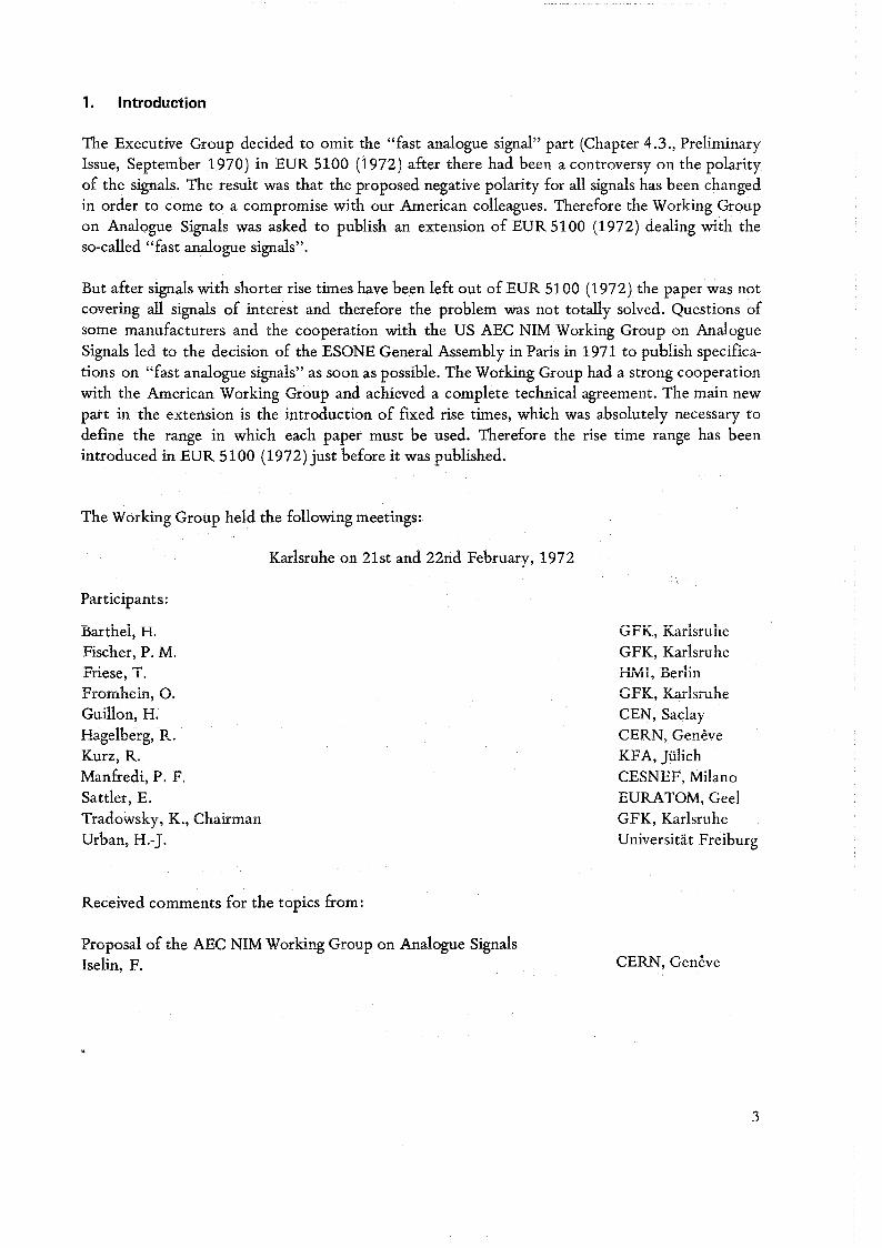
1. Introduction
The Executive Group decided to omit the "fast analogue signal" part (Chapter 4.3., PreliminaryIssue, September 1970) in EUR 5100 (1972) after there had been a controversy on the polarityof the signals. The result was that the proposed negative polarity for all signals has been changedin order to come to a compromise with our American colleagues. Therefore the Working Groupon Analogue Signals was asked to publish an extension of EUR 5100 (1972) dealing with theso-called "fast analogue signals".
But after signals with shorter rise times have been left out ofEUR 5100 (1972) the paper was notcovering an signals of interest and therefore the problem was not totally solved. Questions ofsome manufacturers and the cooperation with the US AEC NIM Working Group on AnalogueSignals led to the decision of the ESONE General Assembly in Paris in 1971 to publish specifications on "fast analogue signals" as soon as possible. The Working Group had a strong cooperationwith the American Working Group and achieved a complete technical agreement. The main newpatt in the extension is the introduction of fixed rise times, which was absolutely necessary todefine the range in which each paper must be used. Therefore the rise time range has beenintroduced in EUR 5100 (1972) just before it was published.
The Working Group held the following meetings:
Karlsruhe on 21st and 22nd February, 1972
Participants:
Barthel, H.Fischer, P. M.Friese, T.Fromhein, O.Guillon, H.Hagelberg, R.Kurz, R.Manfredi, P. F.Sattler, E.Tradowsky, K., ChairmanUrban, H.-J.
Received comments for the topics from:
Proposal of the AEC NIM Working Group on Analogue SignalsIselin, F.
GFK, KarlsruheGFK, KarlsruheHI\4I, BerlinGFK, KarlsruheCEN, SaclayCERN, Geneve
KFÄ, JülichCESNEF, MilanoEURATOM, GeelGFK, KarlsruheUniversität Freiburg
CERN, Geneve
3
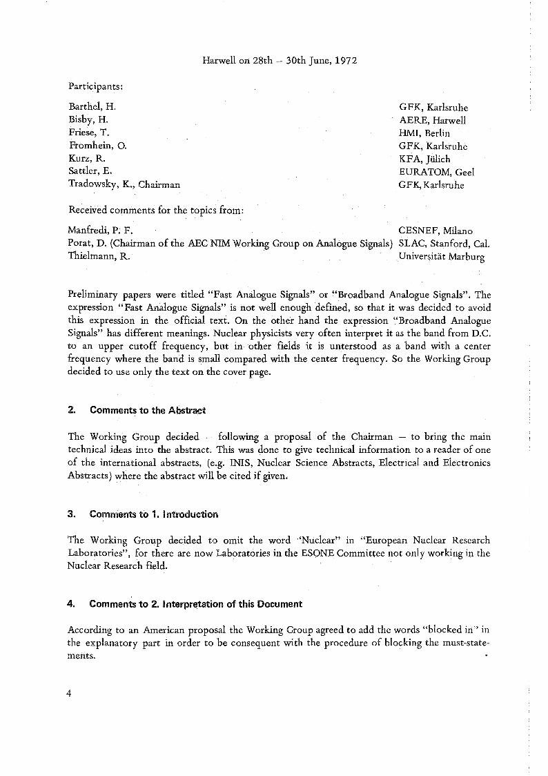
Harwell on 28th - 30th June, 1972
Participants:
Barthel, H.Bisby, H.Friese, T.Fromhein, O.Kurz, R.Sattler, E ..Tradowsky, K., Chairman
Received comments for the topicsfrom:
Manfredi, P. F.Porat, D. (Chairman of the ABC NIM Working Group on Analogue Signals)Thielmann, R.
GFK, KarlsruheAERE, HarwellHMI, BerlinGFK, KarlsruheKFA, JülichEURATOM, GeelGFK, Karlsruhe
CESNEF, MilanoSLAC, Stanford, Ca!.Universität Marburg
Preliminary papers were titled "Fast Analogue Signals" or "Broadband Analogue Signals". Theexpression "Fast Analogue Signals" is not well enough defined, so that it was decided to avoidthis expression in the official text, On the other hand the expression "Broadband AnalogueSignals" has different meanings. Nuclear physicists very often interpret it as the band from DiC.to an upper cutoff frequency, but in other fields it is unterstood as a band with a centerfrequency where the band is small compared with the center frequency. So the Working Groupdecided to use only the text on thecover page.
2. Comments to the Abstract
The Working Group decided - following a proposal of the Chairman - to bring the maintechnical .ideas into the abstract. This was done to give technical information to a reader of oneof the international abstracts, (e.g. INIS, Nuclear Science Abstracts, Electrical and ElectronicsAbstracts) where the abstract will be cited if given.
3. Comments to 1. Introduction
The Working Group decided to omit the word "Nuclear' in "European Nuclear ResearchLaboratories", for there are now Laboratories in the ESONE Committee not only working in theNuclear Research Held.
4. Comments to 2. Interpretation of this Document
According to an American proposal the Working Group agreed to add the words "hlocked in" inthe explanatory part in order to be consequent with the procedure of blocking the rnust-statements.
4
5. Comments to 3. Specification of Amplitude Analogue Signals
The need for the interaction of information handling systems between CAMAC units led to thenecessity of specifying amplitude analogue signals which convey the significant information in aweIl defined form. Whatever characteristic of a signal is chosen to transmit some information, wecan restriet our consideration to the following very general communication system.
This system will include a transmitter, this may be a transducer generating an electrical signal as aresponse of a physical effect, a transmission system over which the signal is transmitted, this maybe a transmission line, a filter etc., and a signal processor which produces at its output the desiredinformation,
Since the transmission systems are restricted in the available bandwidth, there evolve limitationsin the transmitted signal. In the design of transmission networks the frequency concept is widelyused, whereas the rise time concept is often preferred in describing the responses in the timedomain. Both concepts are related to each other depending on what criterion is chosen. Conclusions as to which bandwidth requirements are needed must agree with the transient analysis.
If the output has to be a reproduction of the input with high fidelity the required systembandwidth will be much greater compared with an output which contains only the most significant energy share. The output signal will then be a distorted replica of the input, but it may begood enough for further evaluation.
Besides other definitions we refer to the frequency bandwidth of a lew-pass system as being thefrequency interval between zero and the 3 db cutoff points. In particular, the rise time is definedhere as the time interval between 10 and 90 per cent ofthe final vaiue of the output unit stepresponse. Unfortunately both characteristics show no general relation, that means, changing thetransmission system a different relationship will result.
te = 0(0:»
0'( tl rncx
tr"·~19
Q.ill =.!.. 1. Si rr (211)o(a» 2 Tf 9
0,2 0,4 0,6 0,81.0 1,2 1{. 1,6 1ß .0 2,2 2," 2p 2ß 3,0
0.7
0.9
0.8
-1"
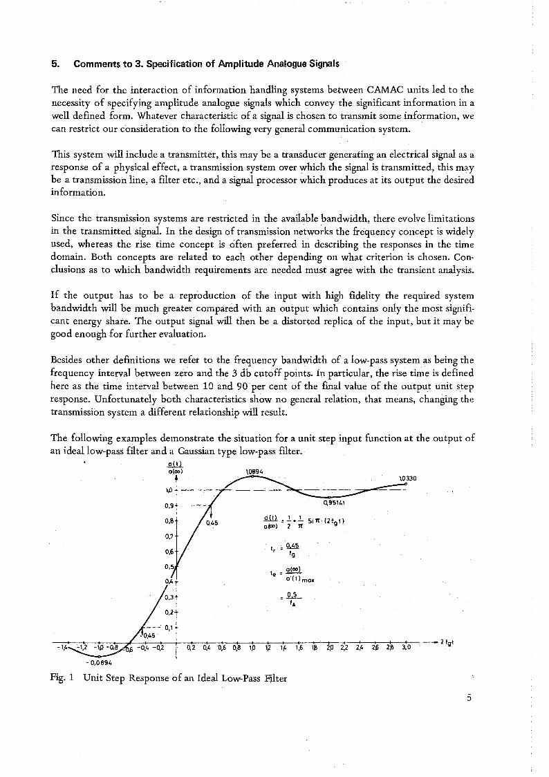
The following examples demonstrate the situation for a unit step input function at the output ofan ideal low-pass filter and a Gaussian type lew-pass filter.
..!ilil.0(0:» 1,0894
l.ot __
- 0.0894
Fig. 1 Unit Step Response of an Ideal Low-Pass Filter
5
The response of the ideal low-pass filter is:
a(t) = aO [0.5 + l/rr • Si(rr • 2fgt)]
with fg being the eutoff frequeney point.
The evaluation yields the relation:
0(1)0(00) 0(1)- =0.5 + 0.5 'erl (V2.1[. 10·t)
0(00)
1.0 -- -- - -- -=-:;;;;...o.....-~. -- --
I
-o.s~~,
-0.4 -0.3 - 0.2I
-0.1
0.9
0.8
0,7
0,2
I
0.1I
0.2
1.( I ) 2I H (I) I =e- 210
Ir = 0.341 te=~13dB 13d B
13dB ='O'YiiiT
I0.'
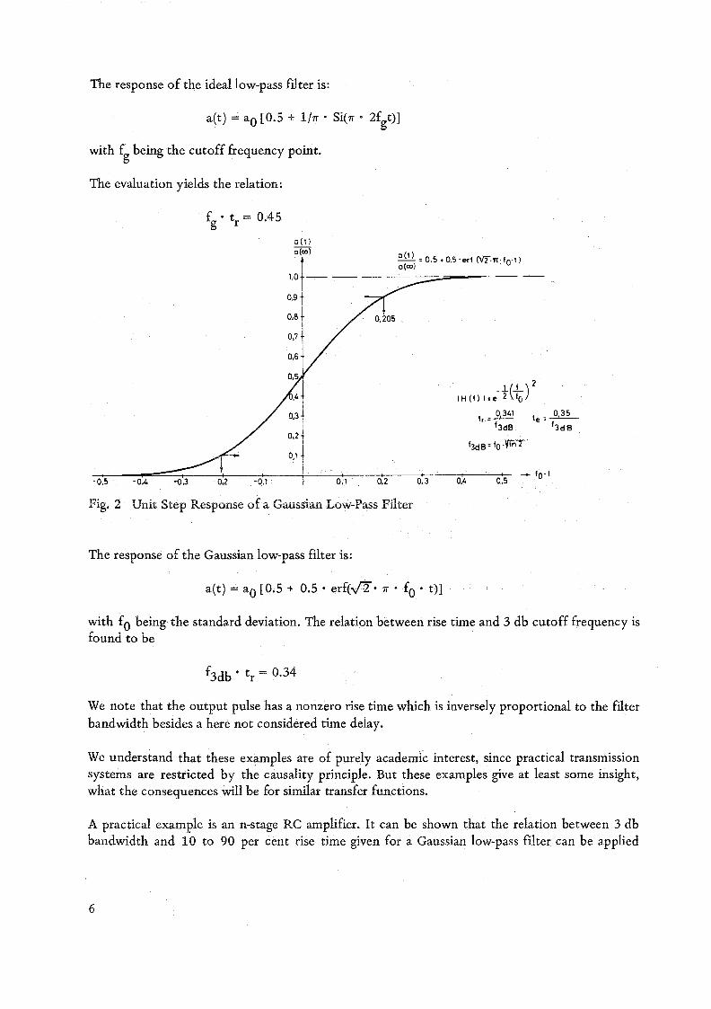
Unh Step Response of a Gaussian Low-Pass FUter
The response of the Gaussian lew-pass filter is:
a(t) = aO [0.5 + 0.5· erf(-y'2· tt • fO• t)]
with fO being the standard deviation, The relation between rise time and 3 db eutoff frequeney isfound to be
We note that the output pulse has a nonzero rise time which is inversely proportional to the filterbandwidth besides a here not considered time delay.
We understand that these examples are of p.urely academic interest, since praetical transmissionsystems are restricted by the causality principle, But these examples give at least some insight,what the eonsequences will be for similar transfer functions.
A practical example is an n-stage Re amplifier. It can be shown that the relation between 3 dbbandwidth and 10 to 90 per eent rise time given for a Gaussian lew-pass filter can be applied
6
within a few per cent of error for RC amplifiers, The larger n is the better is the approximationby a Gaussian type function and therefore the better is the application of the above mentionedrelation.
Forpractical purpose this relationship has been referred to in the Specification of AmplitudeAnalogue Signals.
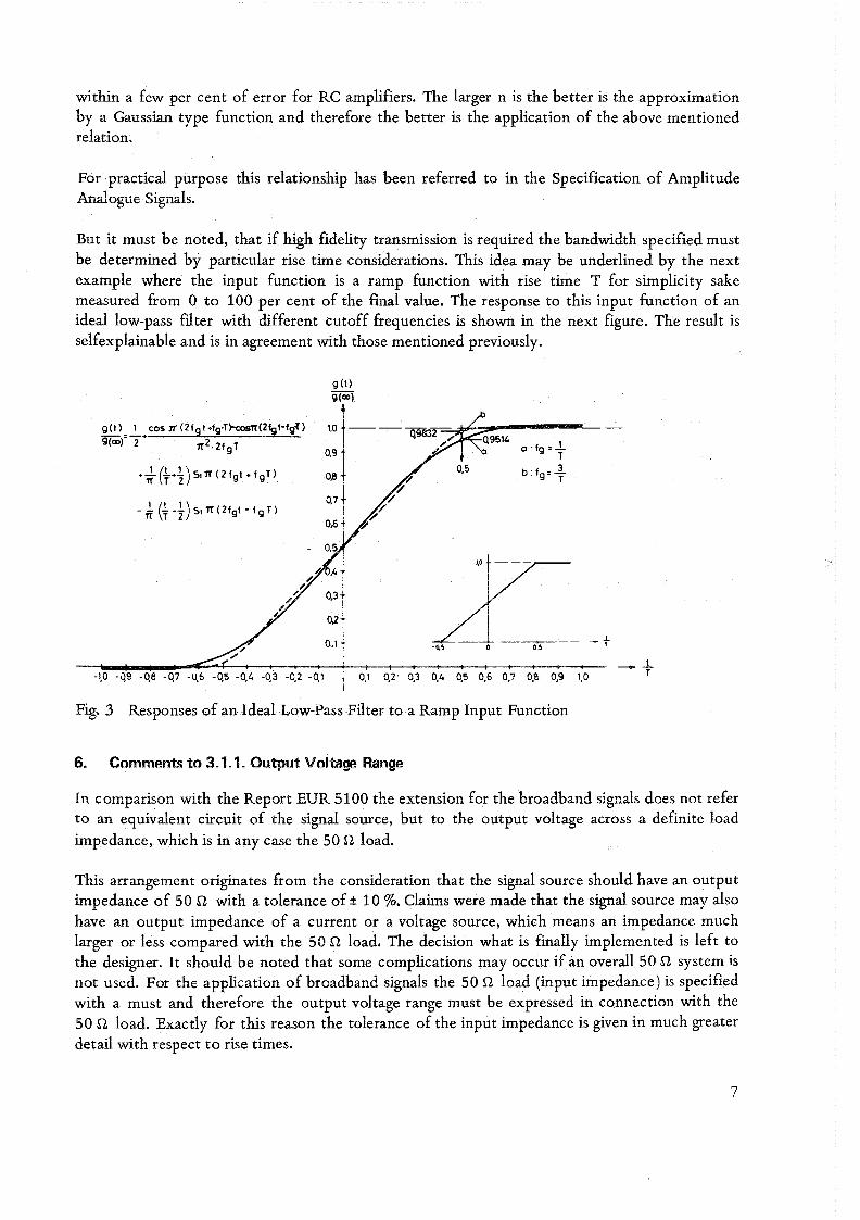
But it must be noted, that if high fldelity transmission is required the bandwidth specified mustbe determined by particular rise time considerations. This idea may be underlined by the nextexample where the input function is a ramp function with rise time T for simplicity sakemeasured from 0 to 100 per cent of the final value. The response to this input function of anideal low-pass filter with different cutoff frequencies is shown in the next figure. The result isselfexplainable and is in agreement with those mentioned previously.
9(1)
9(CIl)
~_~+ cos 1f (2191 +lg-n·cos1f(2fgt-fg'l')
g(CIlf 2 7f2'21 g T
+~ (t+1) S,1f (2191 +fgTl
-k(t -I) Si 1f (2191 - 19 T)
0: Ig =.1.T
b: 19 = ~
0,1 0,2' 0,3 0,4 0,5 0,6 0,7 O,ß 0,9 1,0
y-LI
-1,0 -y9 -0.8 -0.7 -ue -0.5 -0,4 -0.3 -0,2 -0,1
-0.5 0 0,5 -- {-_ ..L
T
Fig. 3 Responses of an Ideal Low-PassFilter to a Ramp Input Function
6. Comments to 3.1.1. Output Voltage Range
In comparison with the Report EUR 5100 the extension for the broadband signals does not referto an equivalent circuit of the signal source, but to the output voltage across a definite load
impedance, which is in any case the 50 Q load.
This arrangement originates from the consideration that the signal source should have an outputimpedance of 50 Q with a tolerance of ± 10 %. Claims were made that the signal source may alsohave an output impedance of a current or a voltage source, which means an impedance muchlarger or less compared with the 50 Q load, The decision what is finaHy implemented is left tothe designer. It should be noted that some complications may occur if an overall 50 Q system isnot used. For the application of broadband signals the 50 Q load (input impedance) is specifiedwith a must and therefore the output voltage range must be expressed in connection with the50 Q load. Exactly for this reason the tolerance of the input impedance is given in much greaterdetail with respect to rise times.
7
7. Comments to 3.1.2. Maximum Output Voltage
In the statement of the maximum output voltage range it is said that the absolute maximumrange of an output voltage across aSO Q load must be - 4 V to + 4 V. The range itself can easilybe understood if we realize that a load impedance may be connected with a voltage source withan output impedance of 50 Q or much less or much larger than 50 Q The main danger arises ifthe output impedance of a current source is drastically decreased for some faulty reason. Using avoltage source the highest voltage range may happen to be - 2 V to + 2 V across a 50 Q load.The maximum range is chosen to be twice as large. The equal range with respect to the zero levelis selfexplainable, if we note that the polarity must be negative and that provision may also bemade to provide for positive polarity.
8. Comments to 3.1.4. Output Impedance
It was the purpose of the specification to recommend a terminated 50 Q system, even if the useof a voltage or a current source is allowed. If perfect matching is provided no difficulties shouldarise. But if the output impedance is not 50 Q reflections will occur. Because of discontinuitiesreflections will appear at the source and will interfere at the output with the desired signal. Inorder to prevent reflections the advisable technique is to arrange an overall terminated 50 Q
system.
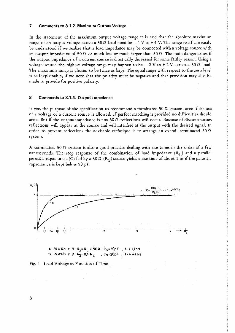
A terminated 50 Q system is also a good practice dealing with rise times in the order of a fewnanoseconds, The step response of the combination of load impedance (RL) and a parallelparasitic capacitance (C) fed by a 50 Q (RS) source yie1ds a rise time of about 1 ns if the parasitic
capacitance is kept below 20 pP.
432o-f'L--+--+---+---+--+--------+--------+-------+-- _ ..L
o 0,2 0.4 Q6 0,8 1 1'0
A: Ri = Ra z. B. R:;= RL = 50R , Cs=20pF , tr =Uns
B: Ri <Ra z. B. RS= 0,'· RL ' Cs=20pF • trtt: 44ps
Fig, 4 Load Voltage as Function of Time
8
t r = T • In 9 = 2.2 T
with T= (Rs 11 RL)' C
This is surely a very simple example but it demonstrates that a 50 n terminated system canprovide rise times in the order of one nanosecond.
9. Comments to 3.2.1. Input Impedance
The specification of broadband signals demands the implementation of a 50 n input (loadimpedance) with a tolerance specified with respect to different pulse rise times.
The question is why this effort? Since the input impedance must be 50 n special care must betaken whether this statement can be met in the considered range of rise times. Unfortunatelythere exists a technical limitation which is caused by properties of the connectors, The load islinked together with the other network via connectors. Mechanical size and costs restriet the useto a limited number of types. The properties of the connectors do not aHowa narrow tolerancescheme for the fuH range of pulse rise times,
SWR ~ 1 + 2· P
ßZLP ~ 0.5,--
Zw
p~l
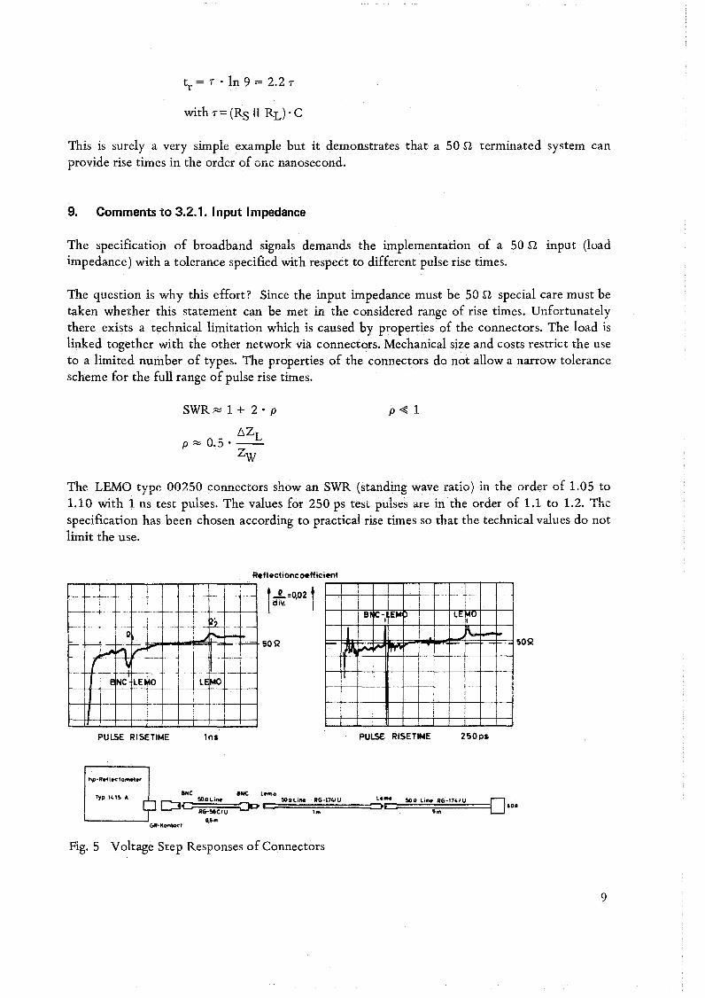
The LEMO type 00250 connectors show an SWR (standing wave ratio) in the order of 1.05 to1.10 with 1 ns test pulses. The values for 250 ps test pulses are in the order of 1.1 to 1.2. Thespecification has been chosen according to practical rise times so that the technical values do notlimit the use.
Refleclioncoefficienl
.• .i.,f--t--- .- t-+-+-t- -+f-. ~. -
~T~~· .... -
-I"'"-, -f-. , \/- ..- c-·· .- _.
··-t,..-LEeNe LE 0 MO
... . -
- ----"- -. -- .-f-- .-
t.J..:0.02 tIdiV. I
50S<
..- .. -
B .. - EM LE~uI
J i\-_.1111"r",
..- ._..- _.
502
PULSE RISETIME Ins PULSE RISETIME 250ps
GR-Kontoct
Typ U.l!t A8Ne
I'--:::a soSILi"..
l..--"C ll6-!ltCIUo,Sm
RG-I741U
1m
Lo",o
:::::>c:!GD li.RG-174'U
Sm
Fig. 5 Voltage Step Responses of Connectors
9

But any other connector type may be used if its properties as weIl as the mechanical conditionsare compatible. The specification does not limit the use of the connectors with shorter rise times,which means that they may show in such a casehigher SWR's.
10