Embed Size (px)
Citation preview

ENGLISH - PAGES 6-9
ESPANOL - PAGINAS 10-13
FRANÇAIS - PAGES 14-17
ITALIANO - PAGINE 18-21
DEUTSCH - SEITEN 22-25
26-29
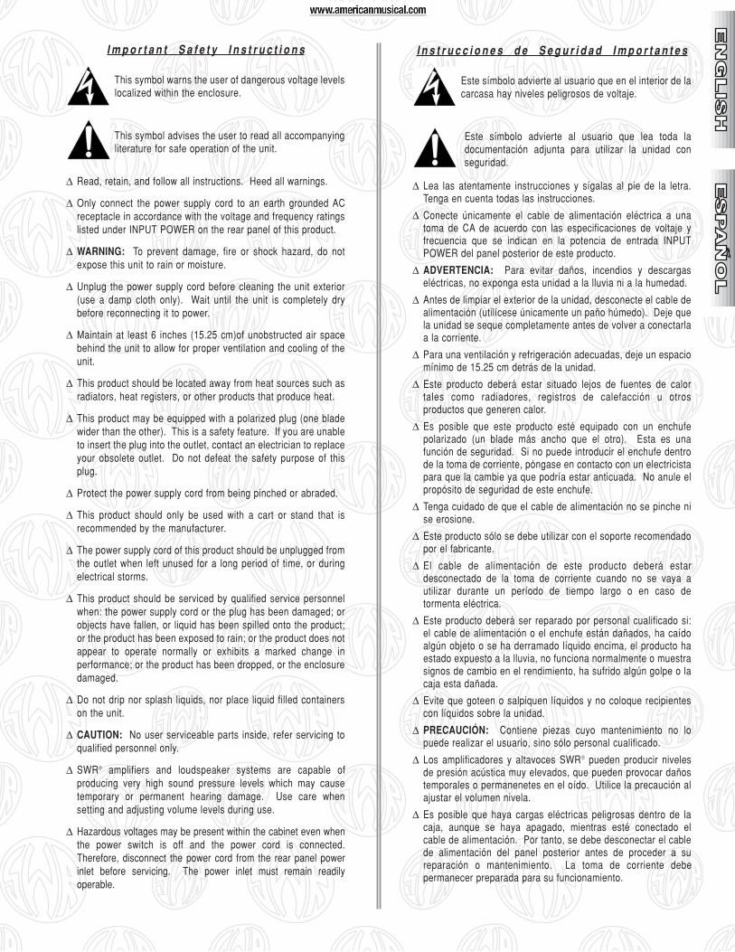
I m p o r t a n t S a f e t y I n s t r u c t i o n s
This symbol warns the user of dangerous voltage levelslocalized within the enclosure.
This symbol advises the user to read all accompanyingliterature for safe operation of the unit.
∆ Read, retain, and follow all instructions. Heed all warnings.
∆ Only connect the power supply cord to an earth grounded ACreceptacle in accordance with the voltage and frequency ratingslisted under INPUT POWER on the rear panel of this product.
∆ WARNING: To prevent damage, fire or shock hazard, do notexpose this unit to rain or moisture.
∆ Unplug the power supply cord before cleaning the unit exterior(use a damp cloth only). Wait until the unit is completely drybefore reconnecting it to power.
∆ Maintain at least 6 inches (15.25 cm)of unobstructed air spacebehind the unit to allow for proper ventilation and cooling of theunit.
∆ This product should be located away from heat sources such asradiators, heat registers, or other products that produce heat.
∆ This product may be equipped with a polarized plug (one bladewider than the other). This is a safety feature. If you are unableto insert the plug into the outlet, contact an electrician to replaceyour obsolete outlet. Do not defeat the safety purpose of thisplug.
∆ Protect the power supply cord from being pinched or abraded.
∆ This product should only be used with a cart or stand that isrecommended by the manufacturer.
∆ The power supply cord of this product should be unplugged fromthe outlet when left unused for a long period of time, or duringelectrical storms.
∆ This product should be serviced by qualified service personnelwhen: the power supply cord or the plug has been damaged; orobjects have fallen, or liquid has been spilled onto the product;or the product has been exposed to rain; or the product does notappear to operate normally or exhibits a marked change inperformance; or the product has been dropped, or the enclosuredamaged.
∆ Do not drip nor splash liquids, nor place liquid filled containerson the unit.
∆ CAUTION: No user serviceable parts inside, refer servicing toqualified personnel only.
∆ SWR® amplifiers and loudspeaker systems are capable ofproducing very high sound pressure levels which may causetemporary or permanent hearing damage. Use care whensetting and adjusting volume levels during use.
∆ Hazardous voltages may be present within the cabinet even whenthe power switch is off and the power cord is connected.Therefore, disconnect the power cord from the rear panel powerinlet before servicing. The power inlet must remain readilyoperable.
I n s t r u c c i o n e s d e S e g u r i d a d I m p o r t a n t e s
Este símbolo advierte al usuario que en el interior de lacarcasa hay niveles peligrosos de voltaje.
Este símbolo advierte al usuario que lea toda ladocumentación adjunta para utilizar la unidad conseguridad.
∆ Lea las atentamente instrucciones y sígalas al pie de la letra.Tenga en cuenta todas las instrucciones.
∆ Conecte únicamente el cable de alimentación eléctrica a unatoma de CA de acuerdo con las especificaciones de voltaje yfrecuencia que se indican en la potencia de entrada INPUTPOWER del panel posterior de este producto.
∆ ADVERTENCIA: Para evitar daños, incendios y descargaseléctricas, no exponga esta unidad a la lluvia ni a la humedad.
∆ Antes de limpiar el exterior de la unidad, desconecte el cable dealimentación (utilícese únicamente un paño húmedo). Deje quela unidad se seque completamente antes de volver a conectarlaa la corriente.
∆ Para una ventilación y refrigeración adecuadas, deje un espaciomínimo de 15.25 cm detrás de la unidad.
∆ Este producto deberá estar situado lejos de fuentes de calortales como radiadores, registros de calefacción u otrosproductos que generen calor.
∆ Es posible que este producto esté equipado con un enchufepolarizado (un blade más ancho que el otro). Esta es unafunción de seguridad. Si no puede introducir el enchufe dentrode la toma de corriente, póngase en contacto con un electricistapara que la cambie ya que podría estar anticuada. No anule elpropósito de seguridad de este enchufe.
∆ Tenga cuidado de que el cable de alimentación no se pinche nise erosione.
∆ Este producto sólo se debe utilizar con el soporte recomendadopor el fabricante.
∆ El cable de alimentación de este producto deberá estardesconectado de la toma de corriente cuando no se vaya autilizar durante un período de tiempo largo o en caso detormenta eléctrica.
∆ Este producto deberá ser reparado por personal cualificado si:el cable de alimentación o el enchufe están dañados, ha caídoalgún objeto o se ha derramado líquido encima, el producto haestado expuesto a la lluvia, no funciona normalmente o muestrasignos de cambio en el rendimiento, ha sufrido algún golpe o lacaja esta dañada.
∆ Evite que goteen o salpiquen líquidos y no coloque recipientescon líquidos sobre la unidad.
∆ PRECAUCIÓN: Contiene piezas cuyo mantenimiento no lopuede realizar el usuario, sino sólo personal cualificado.
∆ Los amplificadores y altavoces SWR® pueden producir nivelesde presión acústica muy elevados, que pueden provocar dañostemporales o permanenetes en el oído. Utilice la precaución alajustar el volumen nivela.
∆ Es posible que haya cargas eléctricas peligrosas dentro de lacaja, aunque se haya apagado, mientras esté conectado elcable de alimentación. Por tanto, se debe desconectar el cablede alimentación del panel posterior antes de proceder a sureparación o mantenimiento. La toma de corriente debepermanecer preparada para su funcionamiento.
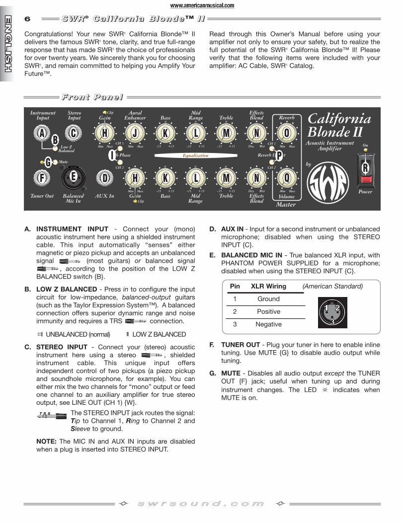
6 SSSS WWWW RRRR® CCCC aaaa llll iiii ffff oooo rrrr nnnn iiii aaaa BBBB llll oooo nnnn dddd eeee™ IIII IIII
Congratulations! Your new SWR® California Blonde™ IIdelivers the famous SWR® tone, clarity, and true full-rangeresponse that has made SWR® the choice of professionalsfor over twenty years. We sincerely thank you for choosingSWR®, and remain committed to helping you Amplify YourFuture™.
Read through this Owner’s Manual before using youramplifier not only to ensure your safety, but to realize thefull potential of the SWR® California Blonde™ II! Pleaseverify that the following items were included with youramplifier: AC Cable, SWR® Catalog.
A. INSTRUMENT INPUT - Connect your (mono)acoustic instrument here using a shielded instrumentcable. This input automatically “senses” eithermagnetic or piezo pickup and accepts an unbalancedsignal (most guitars) or balanced signal
, according to the position of the LOW ZBALANCED switch B.
B. LOW Z BALANCED - Press in to configure the inputcircuit for low-impedance, balanced-output guitars(such as the Taylor Expression System™). A balancedconnection offers superior dynamic range and noiseimmunity and requires a TRS connection.
UNBALANCED (normal) LOW Z BALANCED
C. STEREO INPUT - Connect your (stereo) acousticinstrument here using a stereo , shieldedinstrument cable. This unique input offersindependent control of two pickups (a piezo pickupand soundhole microphone, for example). You caneither mix the two channels for “mono” output or feedone channel to an auxiliary amplifier for true stereooutput, see LINE OUT (CH 1) W.
The STEREO INPUT jack routes the signal:Tip to Channel 1, Ring to Channel 2 andSleeve to ground.
NOTE: The MIC IN and AUX IN inputs are disabledwhen a plug is inserted into STEREO INPUT.
D. AUX IN - Input for a second instrument or unbalancedmicrophone; disabled when using the STEREOINPUT C.
E. BALANCED MIC IN - True balanced XLR input, withPHANTOM POWER SUPPLIED for a microphone;disabled when using the STEREO INPUT C.
F. TUNER OUT - Plug your tuner in here to enable inlinetuning. Use MUTE G to disable audio output whiletuning.
G. MUTE - Disables all audio output except the TUNEROUT F jack; useful when tuning up and duringinstrument changes. The LED indicates whenMUTE is on.
Pin XLR Wiring (American Standard)
1 Ground
2 Positive
3 Negative
FFFF rrrr oooo nnnn tttt PPPP aaaa nnnn eeee llll
ss ww rr ss oo uu nn dd .. cc oo mm

7
H. GAIN - Adjusts the preamp signal level. Use GAIN tobalance the volume levels between the two channelswhile maintaining the optimal signal–to–noise ratio asindicated by the CLIP LED:
CLIP LED - Indicates when the preamp, tone circuits,or output buffer are overdriven (clipping) and causingsignal distortion. The best GAIN setting for minimumdistortion is indicated when CLIP barely flashes atpeak channel input levels (maximum signal strength).This clipping is not harmful to your amplifier, therefore,reduce GAIN for unwanted distortion. Check the CLIPLEDs after adjusting tone or Reverb controls, as theycontribute to the GAIN level.
GAIN also controls the level of all rear panel outputjacks, including EFFECTS SEND Y and can be usedto optimize external equipment connections such asan effects device that is being overdriven (you mayneed to adjust other levels to compensate for GAINchanges). NOTE: If you still hear distortion even at lowGAIN settings (CLIP LED not flashing), check yourguitar battery.
I. PUSH PHASE - Reverses the input/output phase ofeach channel which may reduce “regenerative”feedback occurring at a particular distance from theamplifier. If an instrument or microphone feedback,reverse the phase of that channel or change yourposition/distance from the amplifier.
J. AURAL ENHANCER - Featured on just about everySWR® amplifier since the company’s inception in1984, it is a trademark part of the “SWR Sound”people have come to know and love. It was developedto bring out the fundamental notes of the guitar,enhance the high-end transients, and reduce certainfrequencies that “mask” the fundamentals. Theultimate effect is a more transparent sound that opensup the sibilance characteristics of all instrumentswithout being harsh.
How the AURAL ENHANCER works: Think of it as avariable tone control that changes frequency rangeAND level according to where you set the AURALENHANCER control:
As you rotate the control clockwise from the “MIN”position, you are elevating low, mid, and highfrequency levels in ranges that are different, yetcomplementary to the BASS, MID and TREBLE tonecontrols. The “2 o’clock” position—a favorite for manyusers—brings out both low end fundamentals andcrisp highs while at the same time, adds a little lowermidrange helping you to cut through the band. Then,as you rotate further clockwise, selected mids willdrop off—specifically, a group of frequencies centeredaround 200Hz. While apparent, these curves aregentle, as opposed to the extreme effects you cancreate with the basic tone controls.
Your ears are the best judge when it comes to settingsthat affect the tone of your instrument. Theories aremeaningless if the sound doesn’t satisfy! So, play achord, a repeated lick, or a harmonic, and turn theAURAL ENHANCER control to various points on theknob to hear it for yourself.
K. BASS - Adjusts the low-frequency response of eachchannel. Centered at 110Hz, this range providesfullness as well as the punch to your sound. The BASScontrol has no affect at “0.”
L. MID RANGE - Adjusts middle-frequency response ofeach channel. Centered at 800Hz, this range creates adistinctive edge in your sound which is critical formost instruments. The best setting will depend on thesituation and setting—a MID RANGE setting thatsounds harsh when alone may sound just right in acrowded room or on a recording. MID RANGE has noaffect at “0.”
M. TREBLE - Adjusts high-frequency response of eachchannel. Centered at 3.2kHz, this range adds thebright sparkle to your sound and can bring a dullinstrument to life. Because high-frequencies are“directional” by nature, it is important to listen fromdifferent angles to find the best TREBLE setting andthe optimum placement for your amplifier. TREBLEhas no affect at “0.”
N. EFX BLEND - Controls the level of your effects loop,or more precisely, the ratio of external effects loop(wet) signal, to internal amplifier (dry) signal for eachchannel. Used in conjunction with the rear panelEffects Loop jacks, EFX BLEND is enabled when a1/4" phone plug is inserted into EFFECTSRETURN S.
O. REVERB - Adjusts the level of Reverb for bothchannels.
P. REVERB DEFEAT - Disables REVERB for eachchannel:
REVERB ON REVERB OFF (DEFEATED)
Q. MASTER VOLUME - Adjusts the overall loudness ofof the amplifier after all other controls are set.
R. POWER SWITCH - Switches power on-off to theamplifier as indicated by the LED.
FFFF rrrr oooo nnnn tttt PPPP aaaa nnnn eeee llll—continued
ss ww rr ss oo uu nn dd .. cc oo mm
8 RRRR eeee aaaa rrrr PPPP aaaa nnnn eeee llll
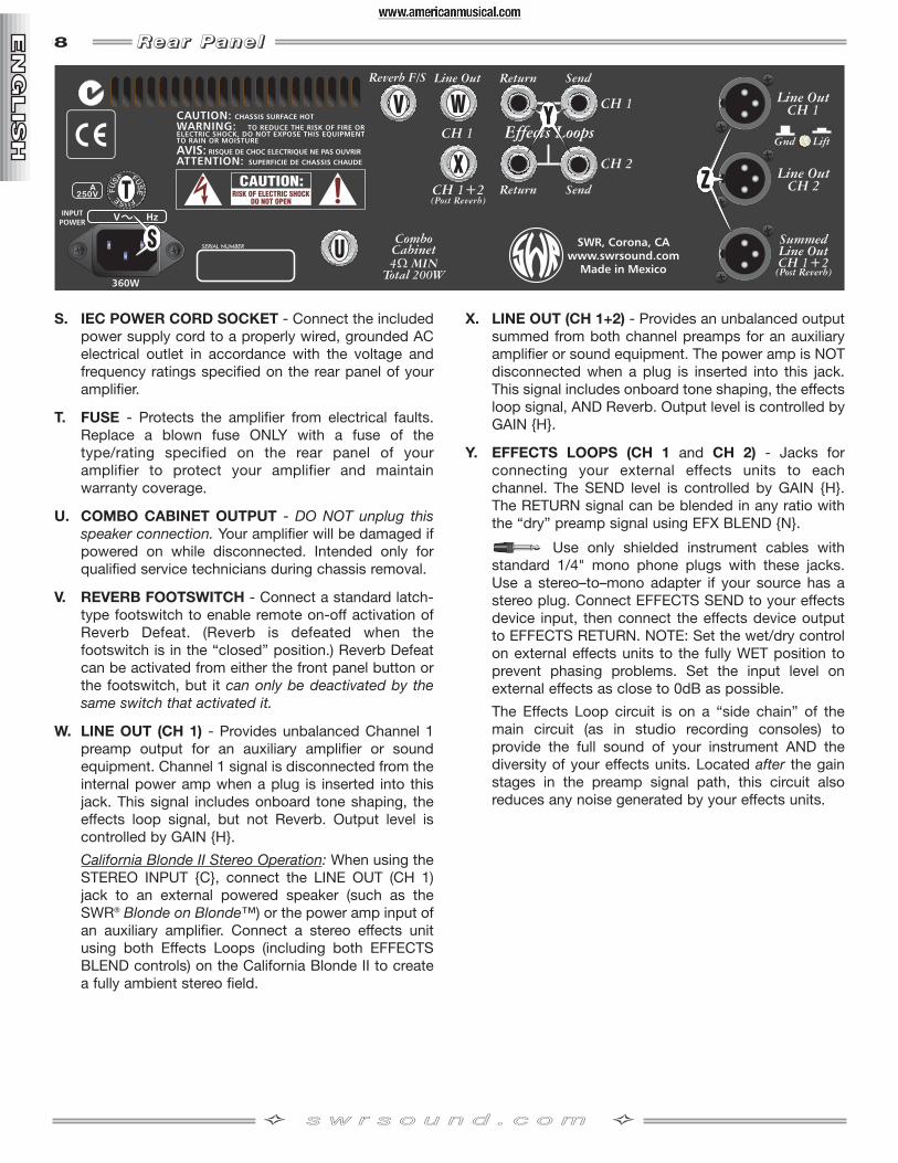
S. IEC POWER CORD SOCKET - Connect the includedpower supply cord to a properly wired, grounded ACelectrical outlet in accordance with the voltage andfrequency ratings specified on the rear panel of youramplifier.
T. FUSE - Protects the amplifier from electrical faults.Replace a blown fuse ONLY with a fuse of thetype/rating specified on the rear panel of youramplifier to protect your amplifier and maintainwarranty coverage.
U. COMBO CABINET OUTPUT - DO NOT unplug thisspeaker connection. Your amplifier will be damaged ifpowered on while disconnected. Intended only forqualified service technicians during chassis removal.
V. REVERB FOOTSWITCH - Connect a standard latch-type footswitch to enable remote on-off activation ofReverb Defeat. (Reverb is defeated when thefootswitch is in the “closed” position.) Reverb Defeatcan be activated from either the front panel button orthe footswitch, but it can only be deactivated by thesame switch that activated it.
W. LINE OUT (CH 1) - Provides unbalanced Channel 1preamp output for an auxiliary amplifier or soundequipment. Channel 1 signal is disconnected from theinternal power amp when a plug is inserted into thisjack. This signal includes onboard tone shaping, theeffects loop signal, but not Reverb. Output level iscontrolled by GAIN H.
California Blonde II Stereo Operation: When using theSTEREO INPUT C, connect the LINE OUT (CH 1)jack to an external powered speaker (such as theSWR® Blonde on Blonde™) or the power amp input ofan auxiliary amplifier. Connect a stereo effects unitusing both Effects Loops (including both EFFECTSBLEND controls) on the California Blonde II to createa fully ambient stereo field.
X. LINE OUT (CH 1+2) - Provides an unbalanced outputsummed from both channel preamps for an auxiliaryamplifier or sound equipment. The power amp is NOTdisconnected when a plug is inserted into this jack.This signal includes onboard tone shaping, the effectsloop signal, AND Reverb. Output level is controlled byGAIN H.
Y. EFFECTS LOOPS (CH 1 and CH 2) - Jacks forconnecting your external effects units to eachchannel. The SEND level is controlled by GAIN H.The RETURN signal can be blended in any ratio withthe “dry” preamp signal using EFX BLEND N.
Use only shielded instrument cables withstandard 1/4" mono phone plugs with these jacks.Use a stereo–to–mono adapter if your source has astereo plug. Connect EFFECTS SEND to your effectsdevice input, then connect the effects device outputto EFFECTS RETURN. NOTE: Set the wet/dry controlon external effects units to the fully WET position toprevent phasing problems. Set the input level onexternal effects as close to 0dB as possible.
The Effects Loop circuit is on a “side chain” of themain circuit (as in studio recording consoles) toprovide the full sound of your instrument AND thediversity of your effects units. Located after the gainstages in the preamp signal path, this circuit alsoreduces any noise generated by your effects units.
ss ww rr ss oo uu nn dd .. cc oo mm

9
Z. XLR OUTPUTS - Studio quality, true electronicallybalanced outputs that provide the ability to sendChannel 1 and 2 separately or together for custommixing. All 3 XLR outputs include onboard toneshaping and the effects loop signal, BUT only theCH 1 + 2 output includes Reverb. Output level iscontrolled by GAIN H, pin wiring is “AmericanStandard”: 1=Ground, 2=(+), 3=(–).
GROUND / LIFT - Disconnects the groundconnection (pin-1) from all 3 XLR outputs, which mayreduce hum noise due a ground loop (non-standardXLR wiring somewhere in the signal path). Normallyleave this switch out.
GROUNDED (normal) GROUND LIFTED
Lifting the ground connection will not solve hum noisedue to bad cables, poor connections, miswired A/Coutlets, nearby fluorescent lighting (especially withsingle-coil pickups) or a cell phone close to yourinstrument.
AA. TWEETER LEVEL CONTROL - Controls the volume of the high-frequency tweeter. Normally,start by setting this control to the“12 o’clock” position, then adjustas desired. Some instrumentssuch as violins, cellos andupright basses may sound bestwith the tweeter off (LEVEL CONTROL fully counter-clockwise). The front panel TREBLE knob controls the
frequency range of the tweeter and can be used as a“high-end pad.”
BB.EXTENSION SPEAKER OUTPUTS - The CaliforniaBlonde II amplifier features both Speakon® and
1/4" phone speaker output jacksto provide flexibility in makingyour extension speakerconnections. Use the Speakon®
jack whenever possible to takeadvantage of its superior power transfer efficiency andlocking connector. Both jacks are full range and wiredin parallel.
• Connect speakers with a total impedance load of 8-ohms minimum to prevent damage to yourequipment (one 8-ohm speaker or two 16-ohmspeakers are acceptable).
• ONLY connect speakers to these outputs.
• ALWAYS switch the amplifier OFF before connectingor disconnecting speakers.
• ONLY use unshielded speaker cable of 18 gauge orheavier (such as 16 or 14 gauge) for speakerconnections. Shielded instrument cable WILL NOTwork and may damage your equipment.
RRRR eeee aaaa rrrr PPPP aaaa nnnn eeee llll—continued
TYPE: PR 628
PART NUMBER: 4460000010 (120V, 60Hz) US 4460001010 (110V, 60Hz) TW4460003010 (240V, 50Hz) AUS 4460004010 (230V, 50Hz) UK4460005010 (220V, 50Hz) ARG 4460006010 (230V, 50Hz) EUR4460007010 (100V, 50Hz) JPN 4460009010 (220V, 60Hz) ROK
POWER REQUIREMENT: 360 W
POWER OUTPUT: 200 W RMS into 4 Ω @ 0.1%THD 150W RMS into 8 Ω @ < 0.02% THD
INPUT IMPEDANCES INSTRUMENT: 3.9M ΩSTEREO: 1M Ω
AUX: 1M Ω
FUSES: F8A 250V for 100V–120V versionsF4A 250V for 220V–240V versions
SPEAKERS: One 8Ω, 200W, 12” stamped frame woofer (P/N 0067084000 )One 16Ω, 25W, supertweeter (crossover 4kHz) (P/N 0067254000)
DIMENSIONS HEIGHT: 25 in (63.5 cm)WIDTH: 15 in (38.1 cm)DEPTH: 14 in (35.6 cm)
WEIGHT: 51 lb (23.1 kg)
Product specifications are subject to change without notice.
SSSS pppp eeee cccc iiii ffff iiii cccc aaaa tttt iiii oooo nnnn ssss
ss ww rr ss oo uu nn dd .. cc oo mm

SWRSWR®
Corona, California USA
SWR® and California Blonde™ are trademarks of Fender Musical Instruments Corporation.Other trademarks are property of their respective owners. © 2004 FMIC. All rights reserved. California Blonde™ II Amplifier • P/N 0065447000 • 10/04