Embed Size (px)
Citation preview

Before using PD-8/CY-8/KD-8/FD-8, you need to make the settings for the percussion sound module (p. 12).
Owner’s ManualThank you and congratulations on your choice of the Roland Dual Trigger Pad PD-8/Dual Trigger Cymbal Pad CY-8/Kick Trigger Pad KD-8/HH Control Pedal FD-8.
03458945 3RC
C
202
Copyright © 2003 ROLAND CORPORATIONAll rights reserved. No part of this publication may be reproduced in any form without the written permission of ROLAND CORPORATION.
Before using this unit, carefully read the sections entitled: “USING THE UNIT SAFELY” and “IMPORTANT NOTES” (p. 2–3). These sections provide important infor-mation concerning the proper operation of the unit. Additionally, in order to feel assured that you have gained a good grasp of every feature provided by your new unit, Owner’s manual should be read in its entirety. The manual should be saved and kept on hand as a convenient
PD/CY/KD/FD-8_e 1 ページ 2004年4月9日 金曜日 午前9時39分
PD/CY/KD/FD-8_e 2 ページ 2004年4月9日 金曜日 午前9時39分
USING THE UNIT SAFELY
001• Before using this unit, make sure to read the
instructions below, and the Owner’s Manual.................................................................................................002a• Do not open or perform any internal modifi-
cations on the unit.................................................................................................003• Do not attempt to repair the unit, or replace
parts within it (except when this manual provides specific instructions directing you to do so). Refer all servicing to your retailer, the nearest Roland Service Center, or an authorized Roland distributor, as listed on the attached “Information” leaflet.
................................................................................................004• Never use or store the unit in places that are:
• Subject to temperature extremes (e.g., direct sunlight in an enclosed vehicle, near a heating duct, on top of heat-generating equipment); or are
• Damp (e.g., baths, washrooms, on wet floors); or are
• Humid; or are
• Exposed to rain; or are
• Dusty; or are
• Subject to high levels of vibration.................................................................................................005• This unit should be used only with a rack or
stand that is recommended by Roland.................................................................................................
006• When using the unit with a rack or stand
recommended by Roland, the rack or stand must be carefully placed so it is level and sure to remain stable. If not using a rack or stand, you still need to make sure that any location you choose for placing the unit provides a level surface that will properly support the unit, and keep it from wobbling.
................................................................................................007• Make sure you always have the unit placed
so it is level and sure to remain stable. Never place it on stands that could wobble, or on inclined surfaces.
................................................................................................011• Do not allow any objects (e.g., flammable
material, coins, pins); or liquids of any kind (water, soft drinks, etc.) to penetrate the unit.
................................................................................................013• In households with small children, an adult
should provide supervision until the child is capable of following all the rules essential for the safe operation of the unit.
................................................................................................014• Protect the unit from strong impact. (Do not drop it!)................................................................................................
Used for instructions intended to alert the user to the risk of injury or material damage should the unit be used improperly.
* Material damage refers to damage or other adverse effects caused with respect to the home and all its furnishings, as well to domestic animals or pets.
Used for instructions intended to alert the user to the risk of death or severe injury should the unit be used improperly.
The ● symbol alerts the user to things that must be carried out. The specific thing that must be done is indicated by the design contained within the circle. In the case of the symbol at left, it means that the power-cord plug must be unplugged from the outlet.
The symbol alerts the user to important instructions or warnings.The specific meaning of the symbol is determined by the design contained within the triangle. In the case of the symbol at left, it is used for general cautions, warnings, or alerts to danger.
The symbol alerts the user to items that must never be carried out (are forbidden). The specific thing that must not be done is indicated by the design contained within the circle. In the case of the symbol at left, it means that the unit must never be disassembled.
2
PD/CY/KD/FD-8_e 3 ページ 2004年4月9日 金曜日 午前9時39分
104• Try to prevent cords and cables from
becoming entangled. Also, all cords and cables should be placed so they are out of the reach of children.
................................................................................................106• Never climb on top of, nor place heavy
objects on the unit.................................................................................................
118• Should you remove nuts, washers, screws,
anchor bolts, etc., make sure to put them in a safe place out of children’s reach, so there is no chance of them being swallowed accidentally.
................................................................................................
3
IMPORTANT NOTES291a
In addition to the items listed under “USING THE UNIT SAFELY” on page 2–3, please read and observe the following:
Placement354b• Do not expose the unit to direct sunlight, place it
near devices that radiate heat, leave it inside an enclosed vehicle, or otherwise subject it to temper-ature extremes. Also, do not allow lighting devices that normally are used while their light source is very close to the unit (such as a piano light), or powerful spotlights to shine upon the same area of the unit for extended periods of time. Excessive heat can deform or discolor the unit.
355b• When moved from one location to another where the
temperature and/or humidity is very different, water droplets (condensation) may form inside the unit. Damage or malfunction may result if you attempt to use the unit in this condition. Therefore, before using the unit, you must allow it to stand for several hours, until the condensation has completely evaporated.
356• Do not allow rubber, vinyl, or similar materials to
remain on the unit for long periods of time. Such objects can discolor or otherwise harmfully affect the finish.
Maintenance401a• For everyday cleaning wipe the unit with a soft, dry
cloth or one that has been slightly dampened with water. To remove stubborn dirt, use a cloth impreg-nated with a mild, non-abrasive detergent. After-wards, be sure to wipe the unit thoroughly with a soft, dry cloth.
402• Never use benzine, thinners, alcohol or solvents of
any kind, to avoid the possibility of discoloration and/or deformation.
Additional Precautions553• Use a reasonable amount of care when using the
unit’s buttons, sliders, or other controls; and when using its jacks and connectors. Rough handling can lead to malfunctions.
556• When connecting / disconnecting all cables, grasp
the connector itself—never pull on the cable. This way you will avoid causing shorts, or damage to the cable’s internal elements.
558d• This instrument is designed to minimize the
extraneous sounds produced when it’s played. However, since sound vibrations can be transmitted through floors and walls to a greater degree than expected, take care not to allow these sounds to become a nuisance to neighbors, especially when performing at night and when using headphones.
add• The pad’s rubber surface may turn white, but this
has no effect on the pad’s function.
4
PD/CY/KD/FD-8_e 4 ページ 2004年4月9日 金曜日 午前9時39分
PD-8
Features• Pad is compatible with dual triggers for separate
head and rim sounds.
• Velocity sensitive pad provides rich expression.
• Compact, 8.5-inch pad allows for greater versatility when setting up.
• When used with a percussion sound module capable of positional sensing, you can obtain tonal changes by varying the location at which the pad is struck.
For details on positional sensing, refer to the documentation for the percussion sound module you’re using.
Contents of the Package
Panel Description
Making the Settings
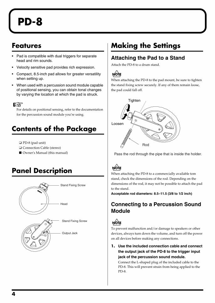
Attaching the Pad to a StandAttach the PD-8 to a drum stand.
When attaching the PD-8 to the pad mount, be sure to tighten the stand fixing screw securely. If any of them remain loose, the pad could fall off.
When attaching the PD-8 to a commercially available tom stand, check the dimensions of the rod. Depending on the dimensions of the rod, it may not be possible to attach the pad to the stand.Acceptable rod diameters: 8.5–11.5 (3/8 to 1/2 inch)
Connecting to a Percussion Sound Module
921
To prevent malfunction and/or damage to speakers or other devices, always turn down the volume, and turn off the power on all devices before making any connections.
1. Use the included connection cable and connect the output jack of the PD-8 to the trigger input jack of the percussion sound module.Connect the L-shaped plug of the included cable to the PD-8. This will prevent strain from being applied to the PD-8.
❑ PD-8 (pad unit)❑ Connection Cable (stereo)■ Owner's Manual (this manual)
Stand Fixing Screw
Stand Fixing Screw
Head
Output Jack
Tighten
Loosen
Rod
Pass the rod through the pipe that is inside the holder.
PD-8
PD/CY/KD/FD-8_e 5 ページ 2004年4月9日 金曜日 午前9時39分
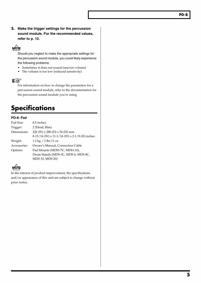
2. Make the trigger settings for the percussion sound module. For the recommended values, refer to p. 12.
Should you neglect to make the appropriate settings for
the percussion sound module, you could likely experience
the following problems:
• Sometimes it does not sound (uneven volume)• The volume is too low (reduced sensitivity)
For information on how to change the parameters for a percussion sound module, refer to the documentation for the percussion sound module you’re using.
SpecificationsPD-8: PadPad Size: 8.5 inchesTrigger: 2 (Head, Rim)Dimensions: 226 (W) x 280 (D) x 54 (H) mm
8-15/16 (W) x 11-1/16 (W) x 2-1/8 (H) inchesWeight: 1.2 kg / 2 lbs 11 ozAccessories: Owner’s Manual, Connection CableOptions: Pad Mounts (MDH-7U, MDH-10),
Drum Stands (MDS-3C, MDS-6, MDS-8C, MDS-10, MDS-20)
962a
In the interest of product improvement, the specifications and/or appearance of this unit are subject to change without prior notice.
5
6
PD/CY/KD/FD-8_e 6 ページ 2004年4月9日 金曜日 午前9時39分
CY-8
Features• Velocity sensitive cymbal pad provides rich
expression.
• Designed specially for cymbals, the pad offers superior playing feel. Realistically reproduces the cymbal’s characteristic “swinging” motion.
• You can use bow shots, edge shots, and choking techniques.
Contents of the Box
Panel Description
Making the Settings
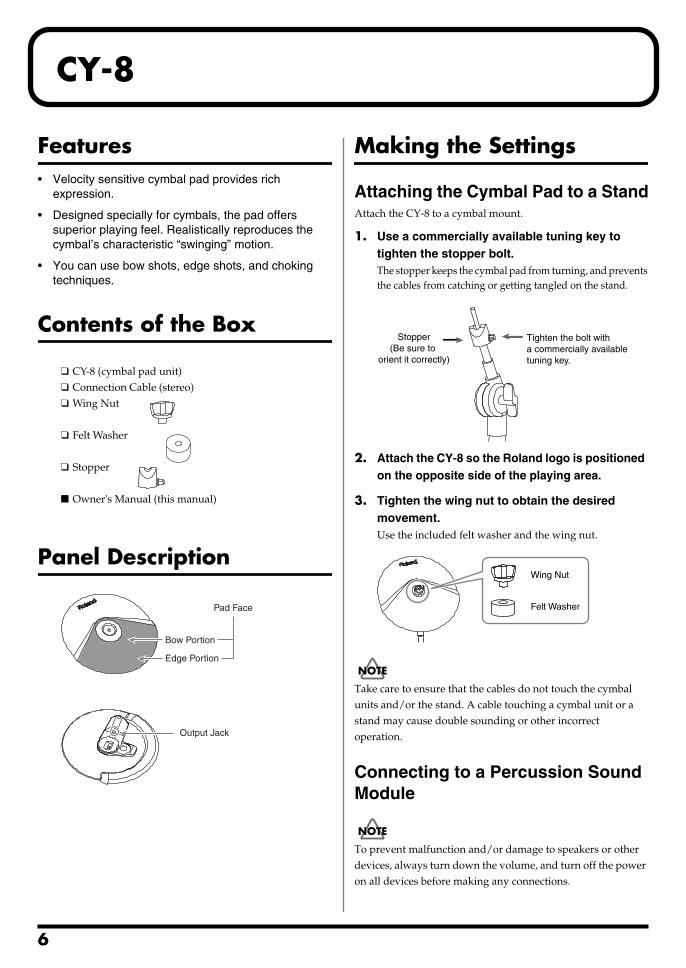
Attaching the Cymbal Pad to a StandAttach the CY-8 to a cymbal mount.
1. Use a commercially available tuning key to tighten the stopper bolt.The stopper keeps the cymbal pad from turning, and prevents the cables from catching or getting tangled on the stand.
2. Attach the CY-8 so the Roland logo is positioned on the opposite side of the playing area.
3. Tighten the wing nut to obtain the desired movement.Use the included felt washer and the wing nut.
Take care to ensure that the cables do not touch the cymbal units and/or the stand. A cable touching a cymbal unit or a stand may cause double sounding or other incorrect operation.
Connecting to a Percussion Sound Module
921
To prevent malfunction and/or damage to speakers or other devices, always turn down the volume, and turn off the power on all devices before making any connections.
❑ CY-8 (cymbal pad unit)❑ Connection Cable (stereo)❑ Wing Nut
❑ Felt Washer
❑ Stopper
■ Owner's Manual (this manual)
Bow Portion
Edge Portion
Pad Face
Output Jack
Stopper(Be sure to
orient it correctly)
Tighten the bolt with a commercially available tuning key.
Wing Nut
Felt Washer
CY-8
PD/CY/KD/FD-8_e 7 ページ 2004年4月9日 金曜日 午前9時39分
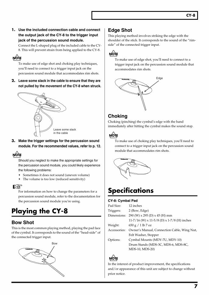
1. Use the included connection cable and connect the output jack of the CY-8 to the trigger input jack of the percussion sound module.Connect the L-shaped plug of the included cable to the CY-8. This will prevent strain from being applied to the CY-8.
To make use of edge shot and choking play techniques, you’ll need to connect to a trigger input jack on the percussion sound module that accommodates rim shots.
2. Leave some slack in the cable to ensure that they are not pulled by the movement of the CY-8 when struck.
fig.CY04a.e
3. Make the trigger settings for the percussion sound module. For the recommended values, refer to p. 12.
Should you neglect to make the appropriate settings for
the percussion sound module, you could likely experience
the following problems:
• Sometimes it does not sound (uneven volume)• The volume is too low (reduced sensitivity)
For information on how to change the parameters for a percussion sound module, refer to the documentation for the percussion sound module you’re using.
Playing the CY-8
Bow ShotThis is the most common playing method, playing the pad face of the cymbal. It corresponds to the sound of the “head-side” of the connected trigger input.
Edge ShotThis playing method involves striking the edge with the shoulder of the stick. It corresponds to the sound of the “rim-side” of the connected trigger input.
To make use of edge shot, you’ll need to connect to a trigger input jack on the percussion sound module that accommodates rim shots.
ChokingChoking (pinching) the cymbal’s edge with the hand immediately after hitting the cymbal makes the sound stop.
To make use of choking play techniques, you’ll need to connect to a trigger input jack on the percussion sound module that accommodates rim shots.
SpecificationsCY-8: Cymbal PadPad Size: 12 inchesTriggers: 2 (Bow, Edge)Dimensions: 290 (W) x 295 (D) x 45 (H) mm
11-7/16 (W) x 11-5/8 (D) x 1-7/8 (H) inchesWeight: 650 g / 1 lb 7 ozAccessories: Owner’s Manual, Connection Cable, Wing Nut,
Felt Washer, StopperOptions: Cymbal Mounts (MDY-7U, MDY-10)
Drum Stands (MDS-3C, MDS-6, MDS-8C, MDS-10, MDS-20)
962a
In the interest of product improvement, the specifications and/or appearance of this unit are subject to change without prior notice.
Leave some slackin the cable
Bow
Edge
7
8
PD/CY/KD/FD-8_e 8 ページ 2004年4月9日 金曜日 午前9時39分
KD-8
Features• Velocity sensitive pad provides rich expression.
• Vertical trigger surface for extremely quiet performance. Also compatible with twin pedals.
Contents of the Box
Panel Description
Making the Settings921
To prevent malfunction and/or damage to speakers or other devices, always turn down the volume, and turn off the power on all devices before making any connections.
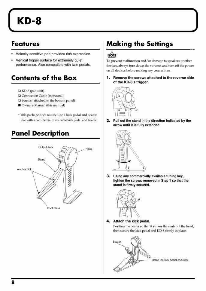
1. Remove the screws attached to the reverse side of the KD-8’s trigger.
2. Pull out the stand in the direction indicated by the arrow until it is fully extended.
3. Using any commercially available tuning key, tighten the screws removed in Step 1 so that the stand is firmly secured.
4. Attach the kick pedal.Position the beater so that it strikes the center of the head, then secure the kick pedal and KD-8 firmly in place.
❑ KD-8 (pad unit)❑ Connection Cable (monaural)❑ Screws (attached to the bottom panel)■ Owner's Manual (this manual)
* This package does not include a kick pedal and beater.
Use with a commercially available kick pedal and beater.
Anchor Bolt
Head
Foot Plate
Stand
Output Jack
Install the kick pedal securely.
Beater
KD-8
PD/CY/KD/FD-8_e 9 ページ 2004年4月9日 金曜日 午前9時39分
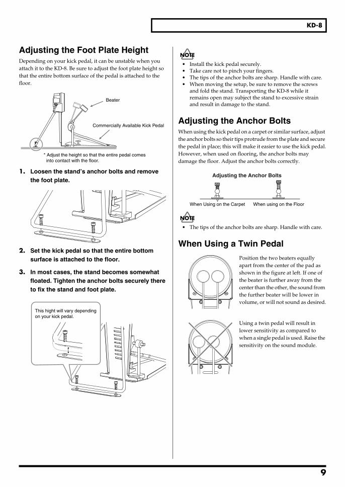
Adjusting the Foot Plate HeightDepending on your kick pedal, it can be unstable when you attach it to the KD-8. Be sure to adjust the foot plate height so that the entire bottom surface of the pedal is attached to the floor.
1. Loosen the stand’s anchor bolts and remove the foot plate.
2. Set the kick pedal so that the entire bottom surface is attached to the floor.
3. In most cases, the stand becomes somewhat floated. Tighten the anchor bolts securely there to fix the stand and foot plate.
• Install the kick pedal securely.• Take care not to pinch your fingers.• The tips of the anchor bolts are sharp. Handle with care.• When moving the setup, be sure to remove the screws
and fold the stand. Transporting the KD-8 while it remains open may subject the stand to excessive strain and result in damage to the stand.
Adjusting the Anchor BoltsWhen using the kick pedal on a carpet or similar surface, adjust the anchor bolts so their tips protrude from the plate and secure the pedal in place; this will make it easier to use the kick pedal.However, when used on flooring, the anchor bolts may damage the floor. Adjust the anchor bolts correctly.
• The tips of the anchor bolts are sharp. Handle with care.
When Using a Twin Pedal
Position the two beaters equally apart from the center of the pad as shown in the figure at left. If one of the beater is further away from the center than the other, the sound from the further beater will be lower in volume, or will not sound as desired.
Using a twin pedal will result in lower sensitivity as compared to when a single pedal is used. Raise the sensitivity on the sound module.
Commercially Available Kick Pedal
Beater
* Adjust the height so that the entire pedal comes into contact with the floor.
This hight will vary depending on your kick pedal.
When Using on the Carpet When using on the Floor
Adjusting the Anchor Bolts
9
KD-8
PD/CY/KD/FD-8_e 10 ページ 2004年4月9日 金曜日 午前9時39分
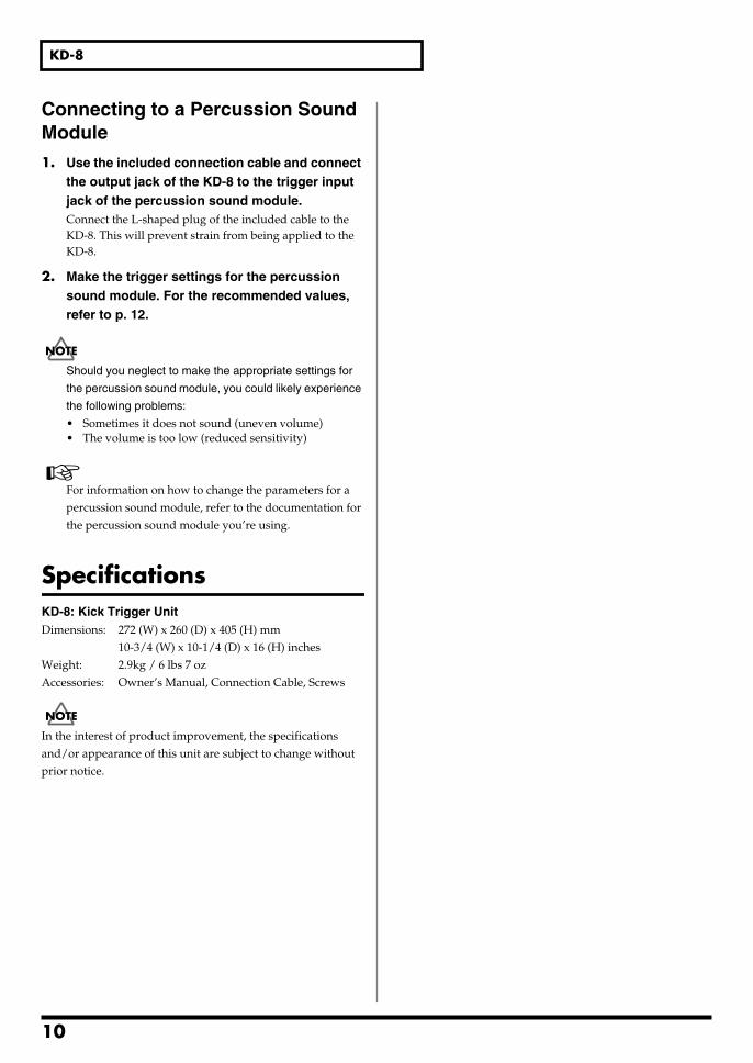
Connecting to a Percussion Sound Module1. Use the included connection cable and connect
the output jack of the KD-8 to the trigger input jack of the percussion sound module.Connect the L-shaped plug of the included cable to the KD-8. This will prevent strain from being applied to the KD-8.
2. Make the trigger settings for the percussion sound module. For the recommended values, refer to p. 12.
Should you neglect to make the appropriate settings for
the percussion sound module, you could likely experience
the following problems:
• Sometimes it does not sound (uneven volume)• The volume is too low (reduced sensitivity)
For information on how to change the parameters for a percussion sound module, refer to the documentation for the percussion sound module you’re using.
SpecificationsKD-8: Kick Trigger UnitDimensions: 272 (W) x 260 (D) x 405 (H) mm
10-3/4 (W) x 10-1/4 (D) x 16 (H) inchesWeight: 2.9kg / 6 lbs 7 ozAccessories: Owner’s Manual, Connection Cable, Screws
962a
In the interest of product improvement, the specifications and/or appearance of this unit are subject to change without prior notice.
10
PD/CY/KD/FD-8_e 11 ページ 2004年4月9日 金曜日 午前9時39分
FD-8
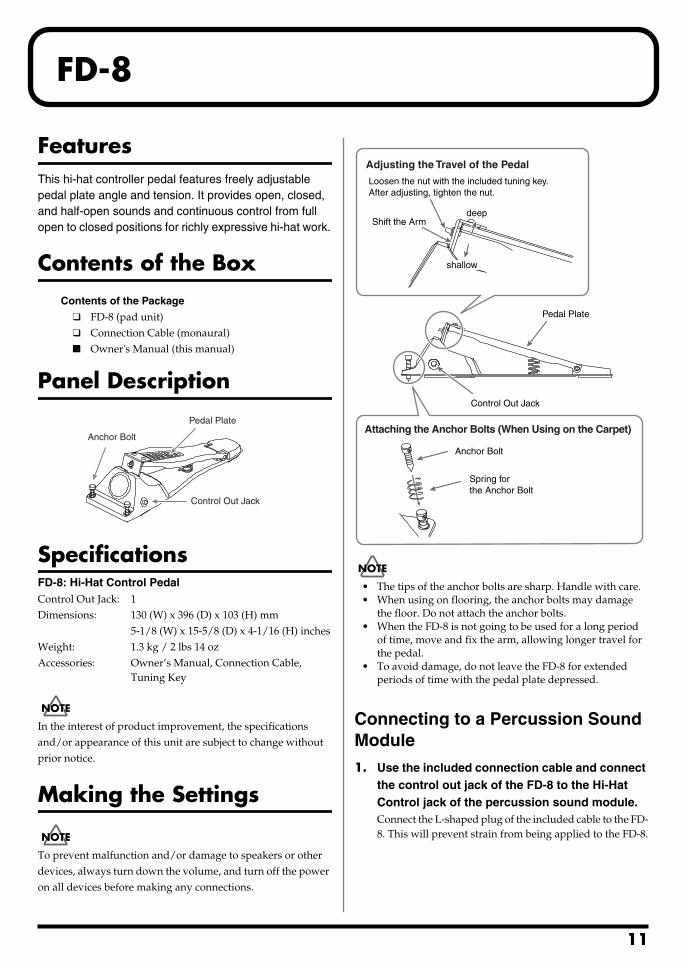
FeaturesThis hi-hat controller pedal features freely adjustable pedal plate angle and tension. It provides open, closed, and half-open sounds and continuous control from full open to closed positions for richly expressive hi-hat work.
Contents of the Box
Panel Description
SpecificationsFD-8: Hi-Hat Control PedalControl Out Jack: 1Dimensions: 130 (W) x 396 (D) x 103 (H) mm
5-1/8 (W) x 15-5/8 (D) x 4-1/16 (H) inchesWeight: 1.3 kg / 2 lbs 14 ozAccessories: Owner’s Manual, Connection Cable,
Tuning Key962a
In the interest of product improvement, the specifications and/or appearance of this unit are subject to change without prior notice.
Making the Settings921
To prevent malfunction and/or damage to speakers or other devices, always turn down the volume, and turn off the power on all devices before making any connections.
• The tips of the anchor bolts are sharp. Handle with care.• When using on flooring, the anchor bolts may damage
the floor. Do not attach the anchor bolts.• When the FD-8 is not going to be used for a long period
of time, move and fix the arm, allowing longer travel for the pedal.
• To avoid damage, do not leave the FD-8 for extended periods of time with the pedal plate depressed.
Connecting to a Percussion Sound Module1. Use the included connection cable and connect
the control out jack of the FD-8 to the Hi-Hat Control jack of the percussion sound module.Connect the L-shaped plug of the included cable to the FD-8. This will prevent strain from being applied to the FD-8.
Contents of the Package
❑ FD-8 (pad unit)❑ Connection Cable (monaural)■ Owner's Manual (this manual)
Anchor Bolt
Pedal Plate
Control Out Jack
shallow
deepShift the Arm
Adjusting the Travel of the Pedal
Control Out Jack
Attaching the Anchor Bolts (When Using on the Carpet)
Anchor Bolt
Spring for the Anchor Bolt
Pedal Plate
Loosen the nut with the included tuning key. After adjusting, tighten the nut.
11
12
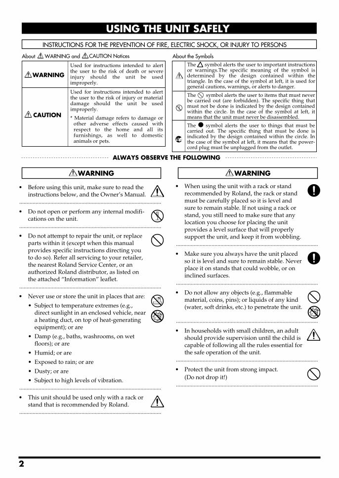
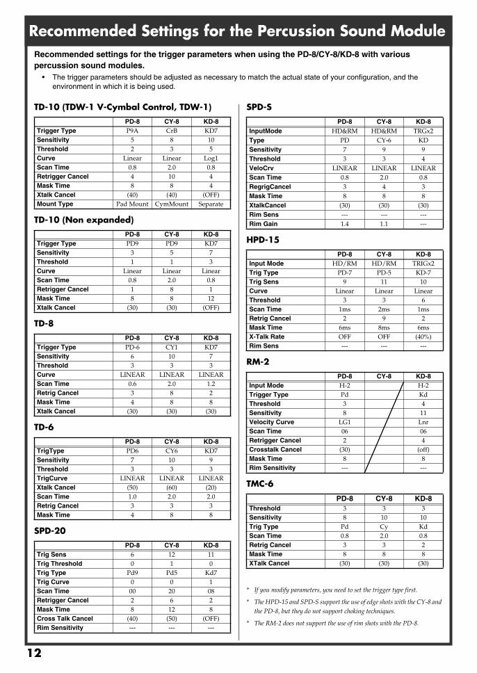
Recommended Settings for the Percussion Sound Module
TD-10 (TDW-1 V-Cymbal Control, TDW-1)
TD-10 (Non expanded)
TD-8
TD-6
SPD-20
SPD-S
HPD-15
RM-2
TMC-6
* If you modify parameters, you need to set the trigger type first.
* The HPD-15 and SPD-S support the use of edge shots with the CY-8 and the PD-8, but they do not support choking techniques.
* The RM-2 does not support the use of rim shots with the PD-8.
PD-8 CY-8 KD-8Trigger Type
P9A CrB KD7
Sensitivity
5 8 10
Threshold
2 3 5
Curve
Linear Linear Log1
Scan Time
0.8 2.0 0.8
Retrigger Cancel
4 10 4
Mask Time
8 8 4
Xtalk Cancel
(40) (40) (OFF)
Mount Type
Pad Mount CymMount Separate
PD-8 CY-8 KD-8Trigger Type
PD9 PD9 KD7
Sensitivity
3 5 7
Threshold
1 1 3
Curve
Linear Linear Linear
Scan Time
0.8 2.0 0.8
Retrigger Cancel
1 8 1
Mask Time
8 8 12
Xtalk Cancel
(30) (30) (OFF)
PD-8 CY-8 KD-8Trigger Type
PD-6 CY1 KD7
Sensitivity
6 10 7
Threshold
3 3 3
Curve
LINEAR LINEAR LINEAR
Scan Time
0.6 2.0 1.2
Retrig Cancel
3 8 2
Mask Time
4 8 8
Xtalk Cancel
(30) (30) (30)
PD-8 CY-8 KD-8TrigType
PD6 CY6 KD7
Sensitivity
7 10 9
Threshold
3 3 3
TrigCurve
LINEAR LINEAR LINEAR
Xtalk Cancel
(50) (60) (20)
Scan Time
1.0 2.0 2.0
Retrig Cancel
3 3 3
Mask Time
4 8 8
PD-8 CY-8 KD-8Trig Sens
6 12 11
Trig Threshold
0 1 0
Trig Type
Pd9 Pd5 Kd7
Trig Curve
0 0 1
Scan Time
00 20 08
Retrigger Cancel
2 6 2
Mask Time
8 12 8
Cross Talk Cancel
(40) (50) (OFF)
Rim Sensitivity
--- --- ---
PD-8 CY-8 KD-8InputMode
HD&RM HD&RM TRGx2
Type
PD CY-6 KD
Sensitivity
7 9 9
Threshold
3 3 4
VeloCrv
LINEAR LINEAR LINEAR
Scan Time
0.8 2.0 0.8
RegrigCancel
3 4 3
Mask Time
8 8 8
XtalkCancel
(30) (30) (30)
Rim Sens
--- --- ---
Rim Gain
1.4 1.1 ---
PD-8 CY-8 KD-8Input Mode
HD/RM HD/RM TRIGx2
Trig Type
PD-7 PD-5 KD-7
Trig Sens
9 11 10
Curve
Linear Linear Linear
Threshold
3 3 6
Scan Time
1ms 2ms 1ms
Retrig Cancel
2 9 2
Mask Time
6ms 8ms 6ms
X-Talk Rate
OFF OFF (40%)
Rim Sens
--- --- ---
PD-8 CY-8 KD-8Input Mode
H-2 H-2
Trigger Type
Pd Kd
Threshold
3 4
Sensitivity
8 11
Velocity Curve
LG1 Lnr
Scan Time
06 06
Retrigger Cancel
2 4
Crosstalk Cancel
(30) (off)
Mask Time
8 8
Rim Sensitivity --- ---
PD-8 CY-8 KD-8Threshold 3 3 3Sensitivity 8 10 10Trig Type Pd Cy KdScan Time 0.8 2.0 0.8Retrig Cancel 3 3 2Mask Time 8 8 8XTalk Cancel (30) (30) (30)
Recommended settings for the trigger parameters when using the PD-8/CY-8/KD-8 with various percussion sound modules.
• The trigger parameters should be adjusted as necessary to match the actual state of your configuration, and the environment in which it is being used.
PD/CY/KD/FD-8_e 12 ページ 2004年4月9日 金曜日 午前9時39分