Embed Size (px)
Citation preview

Calibration of emission
measurement instruments
Hanna-Mari Kaarre, 33240
Processindustriell mätteknik
Institutionen för kemiteknik
Åbo Akademi
Maj 2013
1
Table of Contents
Foreword ............................................................................................................................... 2
Introduction ......................................................................................................................... 2
General information of calibration .............................................................................. 2
Calibration of instruments .............................................................................................. 3
Gases used in calibration ................................................................................................. 6 Pure gases, including zero check gases ............................................................................... 6 Calibration and span gases ...................................................................................................... 7
Emission measurement instruments .......................................................................... 8 Horiba PG-250 .............................................................................................................................. 8 Horiba EXSA-240CL ..................................................................................................................... 9
References .......................................................................................................................... 11

2
Foreword
This report is part of the course “Processindustriell mätteknik”, and the aim of
this report is to enhance students’ knowledge of calibration of exhaust devices
that are used for ship engines. The report will for example contain general
information of calibration, requirements for calibration set up by The Marine
Environment Protection Committee and descriptions of special measuring
devices.
Introduction
The International Maritime Organization (IMO) works on preventing air
pollutions from ships and has been doing it for over 30 years. [3] Depending on
the location there are today different kinds of certificates and standards that
companies are aiming for. These certificates and standards have different
criteria that the engines have to fulfil. In order to check these criteria, test runs
including different measurements are organized. Calibrations are a critical step
of the measurements, since wrongly calibrated instruments will give false
results. Therefore the calibrations must be done correctly and by professionals.
The employees performing the calibration do not need to have a certificate
according to the “Revised Marpol Annex VI, Regulations for the prevention of air
pollution from ships and Technical Code” written by IMO. The employees
are though skilled since the manufacturer provides internal training.
General information of calibration
Decisions made in technical contexts are often based on some measurements,
therefore it is important to be able to show that the measurements are
trustworthy. Without correct measurements, which mean traceable calibrations
with a presented uncertainty, the company risks lower quality, loosing
competitiveness and in the end poor profitability. [4] The definition of
calibration is “the act of checking or adjusting (by comparison with a standard)
the accuracy of measuring instrument”. [6] Calibration is therefore a comparison
between measurements. In calibration for an instrument measuring gas
composition the standard is a specific gas. The composition of the standard gas is
known and will be compared with the measured gas.

3
Calibration of instruments
Every instrument that is used for measuring an engine’s parameters must be
calibrated accordingly to the requirements of the technical code, published
by the international maritime organization. [3] The calibration validity period
varies among the different measurement instruments. The validity period can for
example be between three to twelve months; as for an engine speed
measurement instrument the valid period is three months when it is six months
for a measurement instrument for exhaust gas flow. The calibration validity
period also differs depending on if the measurements are made before achieving
a certificate or if the measurements are made when the engine already is pre-
certified. [3] A pre-certified engine means that the engine already has been
tested and received a certificate for one configuration. The configuration of the
engine can change after this. The new test with the pre-certified engine will often
be done on board of the ship. [3] The certificate type is an “Engine International
Air Pollution Prevention” (EIAPP) certificate, and will be approved by the flag
state marine authority (flag state; “the state under whose laws the vessel is
registered or licensed”)[9]. The requirements of the EIAAP certificate varies on
the location, examples of areas where the requirements are stricter are Baltic Sea
and North Sea. [7] The validity periods between the calibrations will be
presented in the tables below. One calibration can last up to two or three hours.
[5]
It must be possible to track the data from the calibration of the measuring
instruments to standards that are accepted by the administration. A proposal
must be submitted when the calibration procedure or period differs from those
given in the technical code. The proposal must also be submitted and approved
by the administration before the test. [3]

4
NO. Measurement
instrument
Permissible deviation Calibration
validity period
(months)
1 Engine speed ±2% of reading or ±1%
of engine’s maximum
value, whichever is
larger
3
2 Torque ±2% of reading or ±1%
of engine’s maximum
value, whichever is
larger
3
3 Power (where measured
directly)
±2% of reading or ±1%
of engine’s maximum
value, whichever is
larger
3
4 Fuel consumption ±2% of engine’s
maximum value
6
5 Air consumption ±2% of reading or ±1%
of engine’s maximum
value, whichever is
larger
6
6 Exhaust gas flow ±2,5% of reading or
±1,5% of engine’s
maximum value,
whichever is larger
6
“Permissible deviations and calibration validity periods of instruments for
engine-related parameters for measurements on a test bed” [3]

5
NO. Measurement
instrument
Permissible deviation Calibration
validity period
(months)
1 Engine speed ±2% of engine’s
maximum value
12
2 Torque ±5% of engine’s
maximum value
12
3 Power (where measured
directly)
±5% of engine’s
maximum value
12
4 Fuel consumption ±4% of engine’s
maximum value
12
5 Air consumption ±5% of engine’s
maximum value
12
6 Exhaust gas flow ±5% of engine’s
maximum value
12
“Permissible deviations and calibration validity periods of instruments for
engine-related parameters for measurements on board a ship when the engine is
already pre-certified” [3]
6
Gases used in calibration
When using calibration gases and span and zero check gases it is important to
take into account the shelf life of the gases. The person doing the calibration
must document the expiration date of the gases. The manufacturer has defined
the expiration date. [3]
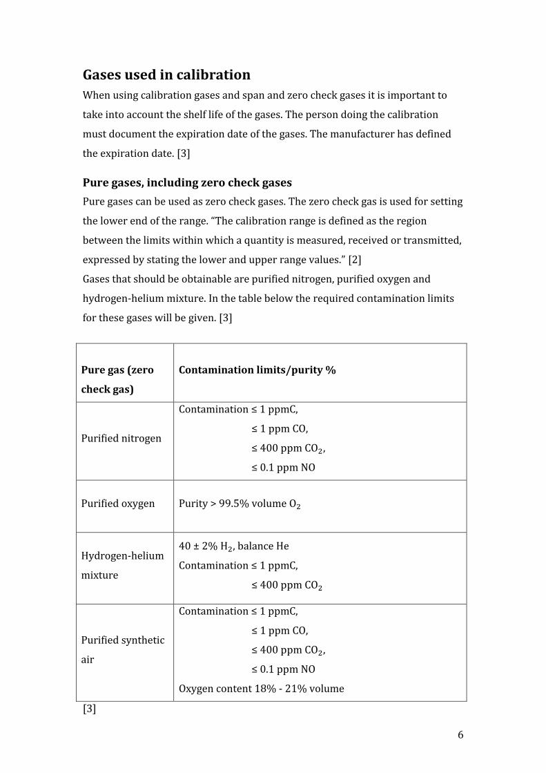
Pure gases, including zero check gases
Pure gases can be used as zero check gases. The zero check gas is used for setting
the lower end of the range. “The calibration range is defined as the region
between the limits within which a quantity is measured, received or transmitted,
expressed by stating the lower and upper range values.” [2]
Gases that should be obtainable are purified nitrogen, purified oxygen and
hydrogen-helium mixture. In the table below the required contamination limits
for these gases will be given. [3]
Pure gas (zero
check gas)
Contamination limits/purity %
Purified nitrogen
Contamination ≤ 1 ppmC,
≤ 1 ppm CO,
≤ 400 ppm ,
≤ 0.1 ppm NO
Purified oxygen Purity > 99.5% volume
Hydrogen-helium
mixture
40 ± 2% , balance He
Contamination ≤ 1 ppmC,
≤ 400 ppm
Purified synthetic
air
Contamination ≤ 1 ppmC,
≤ 1 ppm CO,
≤ 400 ppm ,
≤ 0.1 ppm NO
Oxygen content 18% - 21% volume
[3]

7
Calibration and span gases
The span gases are used for setting up the top end of the calibration range.
Mixtures of gases that should be obtainable are:
- CO and purified nitrogen
- and purified nitrogen ( should not be more than 5% of the NO
content)
- and purified nitrogen
- and purified nitrogen
- and purified synthetic air, or and purified synthetic air. [3]
In addition to these mixtures other gas mixtures can also be used. The only
requirement in that case is that the gases do not react with each other. The
concentration of calibration and span gases should be specified in volume per
cent or volume ppm. The concentration must be comparable with national or
international gas standards. Furthermore, the real concentration of the
calibration must not vary more than 2% compared with the nominal value. This
means that the primary gases have to be known to an accurate rate of ±1%. In
order to obtain the correct concentration of the calibration gases, purified or
purified synthetic air can be used to dilute the gases. The dilution process will be
done by using precision blending devices and for each calibration done using a
blending device, the verification must be made between 15 and 50 % of full scale.
An alternative way of testing the blending device is using an instrument that is
linear by nature. Examples of this kind of instruments are instruments using NO
gas with a Chemiluminescence Detector (CLD). [3]
It is essential that the span gases are directly connected to the instruments when
putting up the span values for the instrument. The blending devices must be
checked at the used settings, so if the settings are being changed the device
should be checked again. The measured concentration of the device must also be
compared to the nominal value. Additionally the difference in each point of he
measurement must not be more or less than 1% of the nominal value. A gas
analyser cannot be linearized with the same gas divider twice. [3]
8
Gases that are used to check the interference of oxygen contain propane or
methane. The amount of hydrocarbons in these gasses should be 350 ppmC ± 75
ppmC. The concentration can for example be checked by chromatographic
analysis of total hydrocarbons and impurities. The dominant diluent should be
nitrogen and the rest will consist of oxygen. [3]
A system leakage test should always be done during a test run. That can be done
with a flow meter or with zero and span gases. In the leakage test done with zero
and span gases concentrations will be compared. At the beginning of the
sampling line there will be a concentration step change when zero gas will be
changed to span gas. After a while the current concentration will be compared to
the concentration at the beginning. If the concentration now is lower than the
concentration at the beginning it means that there is a leakage or calibration
problem. [3]
Emission measurement instruments
Horiba PG-250
Horiba PG-250 is a portable instrument used for measuring , NO, and
. The measurement methods used are for example chemiluminescence for
measuring and a galvanic cell or an optional zirconium oxide sensor for
measuring . [8]
The Horiba PG-250 meets the ISO 8178 standard, which is “an international
standard designed for a number of non-road engine applications.” [1] The ISO
8178 is used in many countries in the European Union, USA and Japan “for
emission certification and/or type approval.” [1]. Horiba PG-250 meets also the
IMO code measurement standards. [5] FINAS Accredited Laboratory, which
follows the EN ISO/IEC 17025 standard guarantee the quality of the Horiba PG-
250.

9
Horiba PG-250. [5]
Horiba EXSA-240CL
Horiba EXSA-240CL is a portable emission measurement system of , NO and
. As the Horiba PG-250 this instrument also meets the ISO 8178 and IMO
code measurement standards. The quality of this device is also guaranteed by
FINAS. The Horiba EXSA-240CL measures with a chemiluminescent
detector and an electro-chemical sensor measures . Both and are
measured on a wet basis. [5]
Horiba EXSA-240CL

10
For all these measurement instruments the calibration requirements set by IMO
are valid. The calibration must in other words be done according to these
requirements and be done by a certified organization.

11
References
[1] DieselNet; Emission Test Cycles ISO 8178,
http://www.dieselnet.com/standards/cycles/iso8178.php, (26.5.2013)
[2] Calibration Principles,
http://www.isa.org/Template.cfm?Section=Find_Books1&template=Ecommerce
/FileDisplay.cfm&ProductID=7577&file=ACFBA59.pdf, (26.5.2013)
[3] International Maritime Organization (2009); Revised Marpol Annex VI,
Regulations for the prevention of air pollution from ships and Technical Code
2008, (26.5.2013)
[4] Swedac; Kalibrering, http://www.swedac.se/sv/Omraden/Kalibrering/,
(20.5.2013)
[5] T. Sundell 19.1.2011; WFI Technical service emission measurement systems,
(21.5.2013)
[6] The free dictionary by farlex, http://www.thefreedictionary.com, (20.5.2013)
[7] DieselNet; Emission standard, International IMO Marine Engine Regulations;
http://www.dieselnet.com/standards/inter/imo.php (30.5.2013)
[8] Horiba Process & Environmental Automotive Test Systems; PG-250 Portable
Multi-Gas Analyzer
http://www.horiba.com/process-
environmental/products/combustion/details/pg-250-portable-multi-gas-
analyzer-264/ (30.5.2013)
[9] Wikipedia; Flag state, https://en.wikipedia.org/wiki/Flag_state (30.5.2013)