Embed Size (px)
Citation preview
XIX IMEKO World CongressFundamental and Applied Metrology
September 6−11, 2009, Lisbon, Portugal
CALIBRATION OF ACCELEROMETERS USING PARAMETER IDENTIFICATION – TARGETING A VERSATILE NEW STANDARD
Thomas Bruns 1, Alfred Link1, Franko Schmähling1, Holger Nicklich2, Clemens Elster1
1 Physikalisch-Technische Bundesanstalt, Germany, [email protected] SPEKTRA Schwingungstechnik und Akustik GmbH, Dresden, Germany
Abstract − The currently established documentary standards [1, 2] for primary accelerometer calibration provide a characterisation of the device under test which is not well suited for the application to transient excitations. The model based parameter identification (MBPI) introduced over the last years [3, 4] may provide better means of characterisation for such types of applications. The method was recently validated with extensive measurement series in a joint research project between PTB and the company “SPEKTRA Schwingungstechnik und Akustik GmbH Dresden” and is now considered by the authors to be ready for practical use and worthwhile to be standardized on an ISO level.
This contribution will shortly re-visit the methodology of MBPI, report on the validation process and finally describe the current effort to implement a new ISO documentary standard on the topic.
Keywords Accelerometer, calibration, identification
1. INTRODUCTION
The international documentary standards currently established for primary accelerometer calibration [1, 2] characterise the device under test either by its (complex) frequency response measured at discrete frequencies or for shock excitation by a ratio of peak values. Neither of the methods is directly useful for applications with transient signals including high frequencies like e.g. high intensity shocks. This leads not only to drawbacks in the industrial application, but results in serious problems concerning the dissemination of units in the field and the necessary comparisons of different devices or laboratories on the level of NMIs as well as in the process of accreditation.
The methodology of MBPI provides the tools to resolve these problems and to realize a concise characterisation of the device under test (DUT) which could be directly used for applications with arbitrary signals including (key) comparison with transient signal types.
The approach taken is a particular mathematical model description of the accelerometer as a dynamic system with mechanical input and electrical output. The estimates of the parameters of that model and the associated uncertainties are then determined on the basis of calibration data achieved with the established methods. The identified model can then be used to either calculate (predict) the time-domain
response of the sensor to arbitrary transient signals (including time dependent uncertainties) or as a starting point for a process to estimate the unknown transient input of the sensor from its measured time-dependent output signal [5].
As a side effect the method usually provides an estimate of a continuous frequency-domain transfer sensitivity of the model, too.
The methodology of MBPI was recently validated within the framework of a technology transfer programme supported by the German Federal Ministry of Economics and Technology in a joint research project of the company “SPEKTRA Schwingungstechnik und Akustik GmbH Dresden” as a manufacturer of calibration systems and the PTB as the research institute which developed the method.
2. THE MODEL BASED APPROACH
2.1. The physical modelThe physical model considered at first stage is that of a
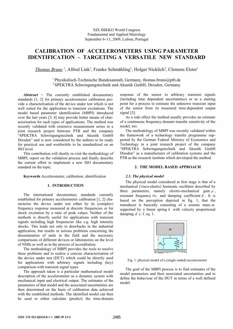
mechanical (visco-elastic) harmonic oscillator described by three parameters, namely electro-mechanical gain , resonant frequency 0 and damping coefficient . It is based on the perception depicted in fig. 1, that the transducer is basically consisting of a seismic mass msupported by a linear spring k with velocity proportional damping d c. f. eq. 1.
Fig. 1: physical model of a (single ended) accelerometer
The goal of the MBPI process is to find estimates of the model parameters and their associated uncertainties and to define the behaviour of the DUT in terms of a well defined model.
2.2. The numerical modelThe equation of motion for a dynamic system like in
fig. 1 reads
x dm x k
m x = x20 x02 x = ⋅at (1)
Starting from this model equation the values of the parameters can be estimated by fitting to the measurement results gathered either from usual primary sinusoidal calibration [1] or from sampled time series acquired with standard equipment for primary high intensity shock calibration [2].
2.3. The identification proceduresThe main identification procedures have already been
extensively described in the above-mentioned publications. Therefore, this section gives only a rough description of what is basically done with the different data taken with the primary calibration systems in use.
The data from the sine-calibration are complex sensitivities at discrete frequencies and associated uncertainties determined according to GUM. They can be interpreted as a (non-equidistant) sampling of the continous complex frequency response of the accelerometer under test. Consequently the complex transfer function of the underlying model could be fitted in terms of weighted linear least squares (WLS), weighted using the uncertainties of the sensitivities, to the measured data.
The continuous complex transfer function used here for the identification with sine-calibration data has the form [3]
G j=S0
1 − 2/02 2j /0
, (2)
with the three parameters S 0, 0 , and to be identified by the fit procedure.
The time series of data taken during the shock excitation calibration measurements, are discrete samples of the input and output of the modelled system, therefore the model equation is to be discretized before any fit can be applied. From this approach a transfer function of the discrete system can be derived. The sampled time series data are than transformed by DFT into the frequency domain and the transfer function of the discretized system is again fitted to the (now equidistant) samples in the frequency domain. This is again done by WLS with weighting according to the associated uncertainties.
The discretized transfer function used for the identification employing shock calibration data has the form [4]
Ge j =b0 e
− je−2j
1 a1e− j a2e−2j (3)
with the three parameters b0 , a1, and a2 to be identified by the fit procedure. Note that the parameters in eq. (2) are not identical to those in eq. (3), however there is a mapping between these parameter sets.
Note further, that both procedures operate in the frequency domain and in both cases a linear fit to the inverse of the actual transfer function is applied. Otherwise the identification would pose a non-linear problem.
In the meantime a procedure operating in the time domain is under consideration by PTB as well.
3. THE VALIDATION PROCESS
For the validation of the method four different calibration facilities were employed in two different laboratories, namely the Working Group “Acceleration” of PTB and the calibration laboratory of the company SPEKTRA which is accredited in the framework of the German calibration service DKD. In both laboratories a sinusoidal calibration facility and a high intensity shock calibration facility, each equipped with heterodyne Laser interferometer, were available and used (c. f. Figs. 2 to 5) . If the assumptions forming the basis of the methods hold, the results derived from MBPI for a selected set of transducers should be consistent (within the given uncertainties) no matter which device was utilized. Furthermore one of the benefits would be the possibility to predict and check the output, for, e.g., a shock measurement based on the parameters derived from sinusoidal calibration results.
The main objective of the project was to evaluate the validity of MBPI for the upper level of the traceability chain. That is, primary methods and reference grade transducers were chosen as targets. Thus the project partners settled for a set of 5 transducers, as listed in table 1.
Table 1. set of transducers investigated in the project
No. Model Type Shock limit
1 Endevco 2270
Back-to-Back 100 km/s²
2 Endevco2270-M8
Single ended 100 km/s²
3 Bruel & Kjaer8305
Back-to-Back 20 km/s²
4 Bruel & Kjaer8305 WH
Single ended 20 km/s²
5 MetraKD 93
Single ended 100 km/s¹
3.1 The facilities and conventional resultsAs already indicated above MBPI enables the user to
compare calibration results from arbitrary excitations. Therefore it was the aim to cover the following cross-comparisons within the project:
• Sine-calibration with shock calibration• Shock-calibration between the two laboratories• Shock calibration at different intensities
The data for these comparisons was taken with either primary calibration facilities for sinusoidal excitation of PTB and Spektra in the frequency range from 40 Hz to 20 kHz at an amplitude of 100 m/s², or the high intensity shock calibration facilities of the respective laboratories
based on Hopkinson bar techniques using intensities from 5 km/s² to 100 km/s².
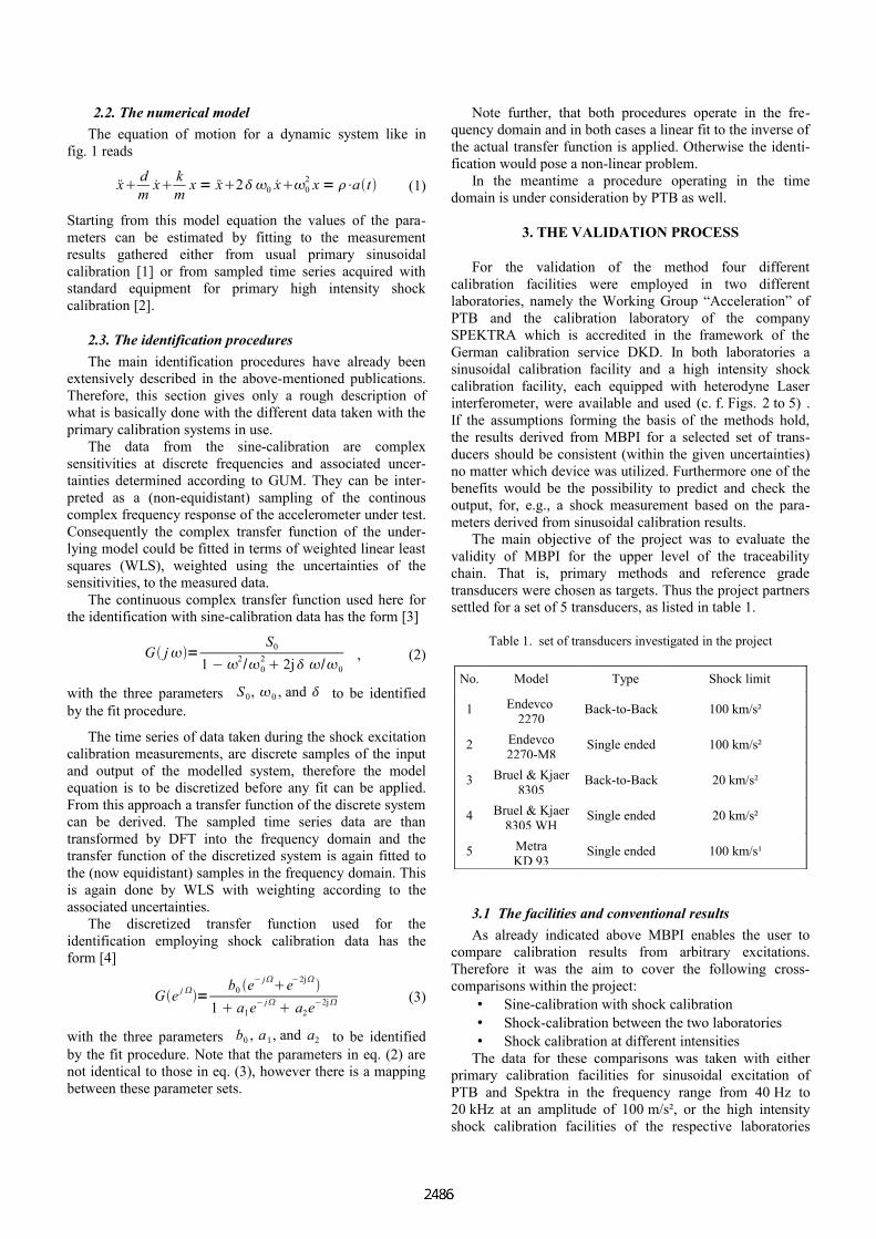
Fig. 2: Sinusoidal calibration device of PTB
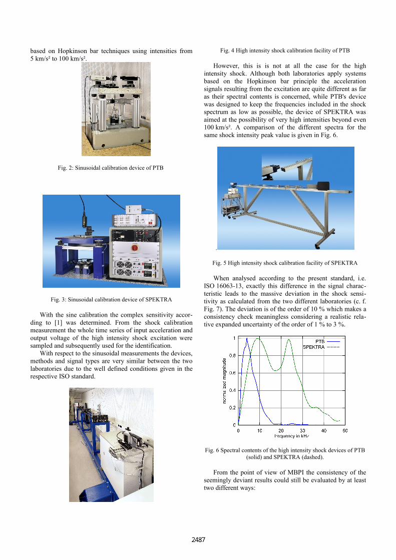
Fig. 3: Sinusoidal calibration device of SPEKTRA
With the sine calibration the complex sensitivity according to [1] was determined. From the shock calibration measurement the whole time series of input acceleration and output voltage of the high intensity shock excitation were sampled and subsequently used for the identification.
With respect to the sinusoidal measurements the devices, methods and signal types are very similar between the two laboratories due to the well defined conditions given in the respective ISO standard.
Fig. 4 High intensity shock calibration facility of PTB
However, this is is not at all the case for the high intensity shock. Although both laboratories apply systems based on the Hopkinson bar principle the acceleration signals resulting from the excitation are quite different as far as their spectral contents is concerned, while PTB's device was designed to keep the frequencies included in the shock spectrum as low as possible, the device of SPEKTRA was aimed at the possibility of very high intensities beyond even 100 km/s². A comparison of the different spectra for the same shock intensity peak value is given in Fig. 6.
.
Fig. 5 High intensity shock calibration facility of SPEKTRA
When analysed according to the present standard, i.e. ISO 16063-13, exactly this difference in the signal characteristic leads to the massive deviation in the shock sensitivity as calculated from the two different laboratories (c. f. Fig. 7). The deviation is of the order of 10 % which makes a consistency check meaningless considering a realistic relative expanded uncertainty of the order of 1 % to 3 %.
Fig. 6 Spectral contents of the high intensity shock devices of PTB (solid) and SPEKTRA (dashed).
From the point of view of MBPI the consistency of the seemingly deviant results could still be evaluated by at least two different ways:
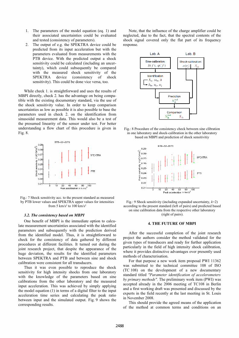
1. The parameters of the model equation (eq. 1) and their associated uncertainties could be evaluated and tested (consistency of parameters).
2. The output of e.g. the SPEKTRA device could be predicted from its input acceleration but with the parameters evaluated from measurements with the PTB device. With the predicted output a shock sensitivity could be calculated (including an uncertainty), which could subsequently be compared with the measured shock sensitivity of the SPEKTRA device (consistency of shock sensitivity). This could be done vice versa, too.
While check 1. is straightforward and uses the results of MBPI directly, check 2. has the advantage on being compatible with the existing documentary standard, via the use of the shock sensitivity value. In order to keep comparison uncertainties as low as possible it is also possible to base the parameters used in check 2. on the identification from sinusoidal measurement data. This would also be a test of the presumed linearity of the sensor under test. For better understanding a flow chart of this procedure is given in Fig. 8.
Fig.: 7 Shock sensitivity acc. to the present standard as measured by PTB lower values and SPEKTRA upper values for intensities
from 5 km/s² to 100 km/s²
3.2. The consistency based on MBPIOne benefit of MBPI is the immediate option to calcu
late measurement uncertainties associated with the identified parameters and subsequently with the prediction derived from the identified model. Thus, it is straightforward to check for the consistency of data gathered by different procedures at different facilities. It turned out during the joint research project, that despite the appearance of the huge deviation, the results for the identified parameters between SPEKTRA and PTB and between sine and shock calibration were consistent for all transducers.
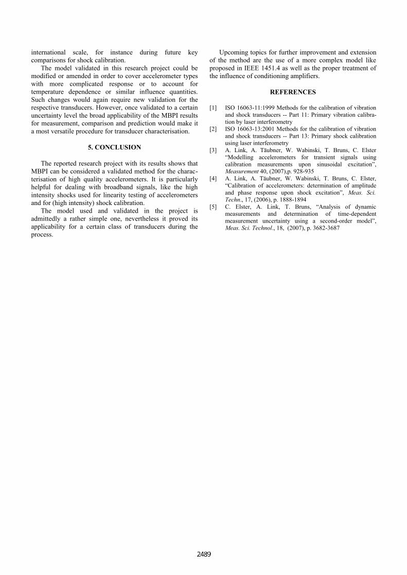
Thus it was even possible to reproduce the shock sensitivity for high intensity shocks from one laboratory with the knowledge of the parameters based on sine calibrations from the other laboratory and the measured input acceleration. This was achieved by simply applying the model equation (1) in terms of a digital filter to the input acceleration time series and calculating the peak ratio between input and the simulated output. Fig. 9 shows the corresponding results.
Note, that the influence of the charge amplifier could be neglected, due to the fact, that the spectral contents of the shock signal covered only the flat part of its frequency response.
Fig.: 8 Procedure of the consistency check between sine clibration in one laboratory and shock-calibration in the other laboratory
based on MBPI and prediction of shock sensitivitiy
Fig.: 9 Shock sensitivity (including expanded uncertainty, k=2) according to the present standard (left of pairs) and predicted based
on sine calibration data from the respective other laboratory (right of pairs).
4. THE FUTURE OF MBPI
After the successful completion of the joint research project the authors consider the method validated for the given types of transducers and ready for further application particularly in the field of high intensity shock calibration, where it provides distinctive advantages over presently used methods of characterisation.
For that purpose a new work item proposal PWI 11362 was submitted to the technical committee 108 of ISO (TC 108) on the development of a new documentary standard titled "Parameter identification of accelerometers by primary methods". The preliminary work item (PWI) was accepted already in the 2006 meeting of TC108 in Berlin and a first working draft was presented and discussed by the experts in the field recently at the last meeting in St. Louis in November 2008.
This should provide the agreed means of the application of the method at common terms and conditions on an
international scale, for instance during future key comparisons for shock calibration.
The model validated in this research project could be modified or amended in order to cover accelerometer types with more complicated response or to account for temperature dependence or similar influence quantities. Such changes would again require new validation for the respective transducers. However, once validated to a certain uncertainty level the broad applicability of the MBPI results for measurement, comparison and prediction would make it a most versatile procedure for transducer characterisation.
5. CONCLUSION
The reported research project with its results shows that MBPI can be considered a validated method for the characterisation of high quality accelerometers. It is particularly helpful for dealing with broadband signals, like the high intensity shocks used for linearity testing of accelerometers and for (high intensity) shock calibration.
The model used and validated in the project is admittedly a rather simple one, nevertheless it proved its applicability for a certain class of transducers during the process.
Upcoming topics for further improvement and extension of the method are the use of a more complex model like proposed in IEEE 1451.4 as well as the proper treatment of the influence of conditioning amplifiers.
REFERENCES
[1] ISO 16063-11:1999 Methods for the calibration of vibration and shock transducers -- Part 11: Primary vibration calibration by laser interferometry
[2] ISO 16063-13:2001 Methods for the calibration of vibration and shock transducers -- Part 13: Primary shock calibration using laser interferometry
[3] A. Link, A. Täubner, W. Wabinski, T. Bruns, C. Elster “Modelling accelerometers for transient signals using calibration measurements upon sinusoidal excitation”, Measurement 40, (2007),p. 928-935
[4] A. Link, A. Täubner, W. Wabinski, T. Bruns, C. Elster, “Calibration of accelerometers: determination of amplitude and phase response upon shock excitation”, Meas. Sci. Techn., 17, (2006), p. 1888-1894
[5] C. Elster, A. Link, T. Bruns, “Analysis of dynamic measurements and determination of time-dependent measurement uncertainty using a second-order model”, Meas. Sci. Technol., 18, (2007), p. 3682-3687