Embed Size (px)
Citation preview
Instruction Manual andExperiment Guide for thePASCO scientific ModelsOS-9255A thru OS-9258A
012-07137B
PRECISIONINTERFEROMETER
IncludesTeacher's Notes
andTypical
Experiment Results
012-07137B Precision Interferometer
� i
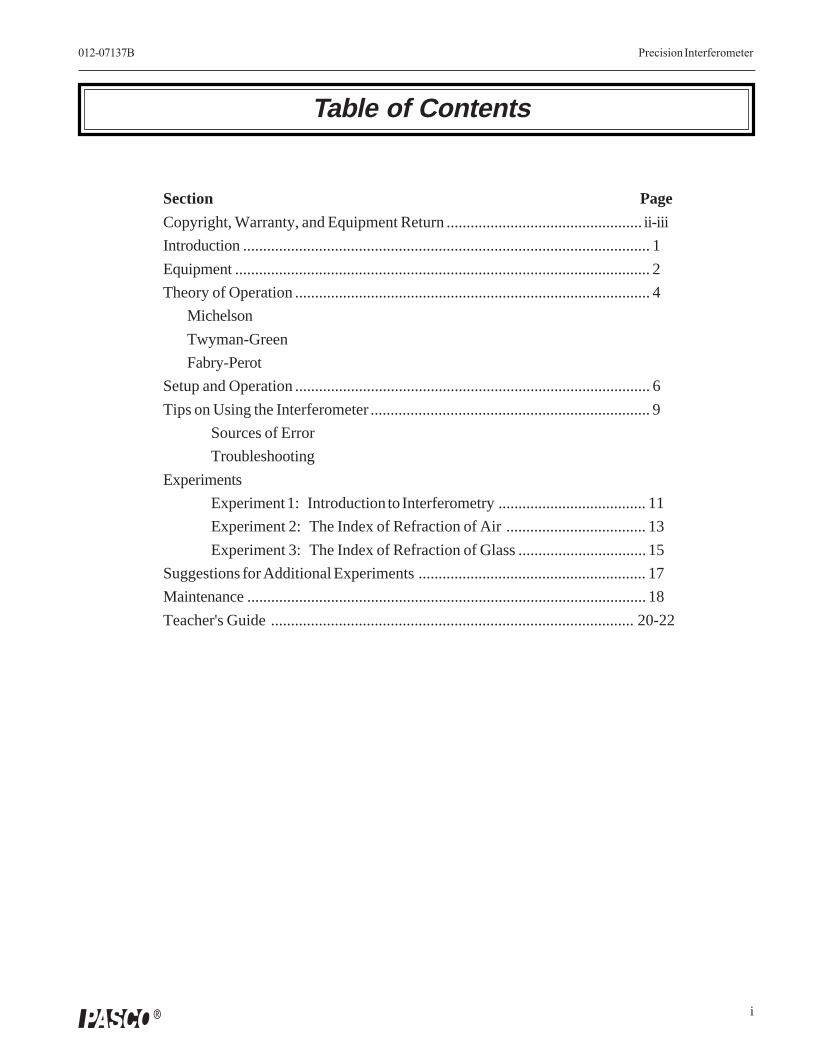
Table of Contents
Section Page
Copyright, Warranty, and Equipment Return ................................................. ii-iii
Introduction ...................................................................................................... 1
Equipment ........................................................................................................ 2
Theory of Operation ......................................................................................... 4
Michelson
Twyman-Green
Fabry-Perot
Setup and Operation ......................................................................................... 6
Tips on Using the Interferometer ...................................................................... 9
Sources of Error
Troubleshooting
Experiments
Experiment 1: Introduction to Interferometry ..................................... 11
Experiment 2: The Index of Refraction of Air ................................... 13
Experiment 3: The Index of Refraction of Glass ................................ 15
Suggestions for Additional Experiments ......................................................... 17
Maintenance .................................................................................................... 18
Teacher's Guide ........................................................................................... 20-22

Precision Interferometer 012-07137B
�
Equipment ReturnShould the product have to be returned to PASCOscientific for any reason, notify PASCO scientific byletter, phone, or fax BEFORE returning the product.Upon notification, the return authorization and shippinginstructions will be promptly issued.
➤➤➤➤➤ NOTE: NO EQUIPMENT WILL BEACCEPTED FOR RETURN WITHOUT ANAUTHORIZATION FROM PASCO.
When returning equipment for repair, the units must bepacked properly. Carriers will not accept responsibilityfor damage caused by improper packing. To be certainthe unit will not be damaged in shipment, observe thefollowing rules:
1. The packing carton must be strong enough for theitem shipped.
2. Make certain there are at least two inches of packingmaterial between any point on the apparatus and theinside walls of the carton.
3. Make certain that the packing material cannot shiftin the box or become compressed, allowing theinstrument come in contact with the packing carton.
Address: PASCO scientific10101 Foothills Blvd.Roseville, CA 95747-7100
Phone: (916) 786-3800FAX: (916) 786-3292email: [email protected]: www.pasco.com
ii
Copyright Notice
The PASCO scientific 012-05187C PrecisionInterferometer manual is copyrighted and all rightsreserved. However, permission is granted to non-profiteducational institutions for reproduction of any part ofthe manual providing the reproductions are used onlyfor their laboratories and are not sold for profit.Reproduction under any other circumstances, withoutthe written consent of PASCO scientific, is prohibited.
Limited Warranty
PASCO scientific warrants the product to be free fromdefects in materials and workmanship for a period ofone year from the date of shipment to the customer.PASCO will repair or replace at its option any part ofthe product which is deemed to be defective in materialor workmanship. The warranty does not cover damageto the product caused by abuse or improper use.Determination of whether a product failure is the resultof a manufacturing defect or improper use by thecustomer shall be made solely by PASCO scientific.Responsibility for the return of equipment for warrantyrepair belongs to the customer. Equipment must beproperly packed to prevent damage and shipped postageor freight prepaid. (Damage caused by improperpacking of the equipment for return shipment will notbe covered by the warranty.) Shipping costs forreturning the equipment after repair will be paid byPASCO scientific.
Copyright, Warranty, and Equipment Return
Please—Feel free to duplicate this manualsubject to the copyright restrictions below.
1
012-07137B Precision Interferometer
�
Introduction
The OS-9255A Precision Interferometer provides both atheoretical and a practical introduction to interferometry.Precise measurements can be made in three modes:
Michelson
The Michelson Interferometer is historically important, andalso provides a simple interferometric configuration forintroducing basic principles. Students can measure thewavelength of light and the indices of refraction of air andother substances.
Twyman-Green
The Twyman-Green Interferometer is an importantcontemporary tool for testing optical components. It hasmade it possible to create optical systems that are accurateto within a fraction of a wavelength.
NOTE: The PASCO Precision Interferometer is notdesigned for actual component testing in theTwyman-Green mode. It is intended only to providea simple introduction to this important application ofinterferometry.
Fabry-Perot
The Fabry-Perot Interferometer is also an importantcontemporary tool, used most often for high resolutionspectrometry. The fringes are sharper, thinner, and morewidely spaced than the Michelson fringes, so small differ-ences in wavelength can be accurately resolved. TheFabry-Perot interferometer is also important in lasertheory, as it provides the resonant cavity in which lightamplification takes place.
Switching between these three modes of operation andaligning components is relatively simple, since all mirrorsmount to the base in fixed positions, using captive panelscrews. Lenses, viewing screens, and other componentsmount magnetically to the base using the included compo-nent holders.
Measurements are precise in all three modes of operation.A 5 kg machined aluminum base provides a stable surfacefor experiments and measurements. All mirrors are flat to1/4 wavelength, and the built-in micrometer resolves mirrormovement to within one micron.
Precision Interferometer 012-07137B
2 �
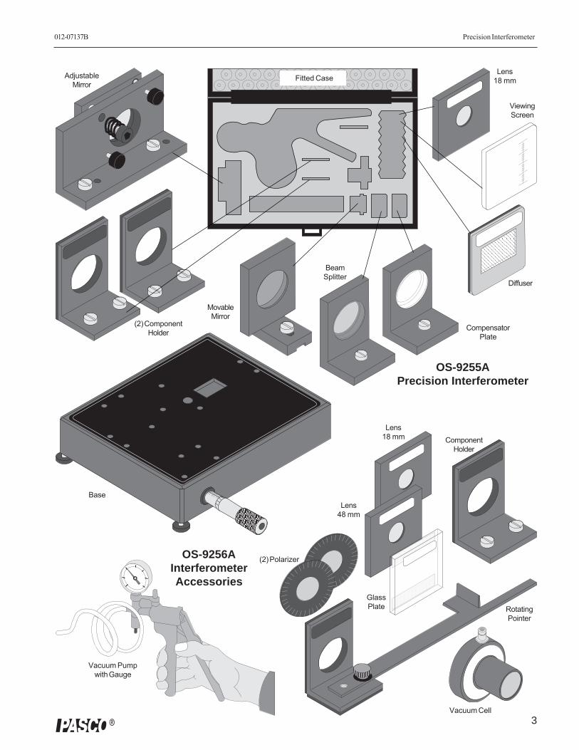
Equipment
The OS-9255A Precision Interferometer includes thefollowing equipment:
• 5 kg Base with built-in micrometer
• Adjustable Mirror
• Movable Mirror
• Beam Splitter
• Compensator Plate
• (2) Component Holder
• Viewing Screen
• Lens, 18 mm Focal Length
• Diffuser
• Fitted Storage Case
Additional Equipment Required –
• Laser (OS-9171)
• Laser Bench (OS-9172)
NOTE:
The preceding equipment includes everything neededfor basic Michelson interferometry. You can pro-duce clear fringes and make precise measurementsof the wavelength of your source. However, toperform the experiments in this manual, you willneed additional components, such as the OS-9256AInterferometer Accessories or a comparable set ofyour own components.The Precision Interferometer is available as acomplete system. Please refer to your currentPASCO catalog for details.
Additional Equipment Recommended –
The OS-9256A Interferometer Accessories includes:
• Rotating Pointer
• Vacuum Cell
• Component Holder
• Lens, 18 mm Focal Length
• Lens, 48 mm Focal Length
• Glass Plate
• (2) Polarizer
• Vacuum Pump with Gauge
NOTE:
The OS-9255A Fitted Case also provides storage forthese accessory components.
About Your Light Source
We strongly recommend a laser for most introductoryapplications. A spectral light source can be used (see theAppendix), but that really comprises an experiment in andof itself for beginning students. A laser source is easy touse and produces bright, sharp fringes.
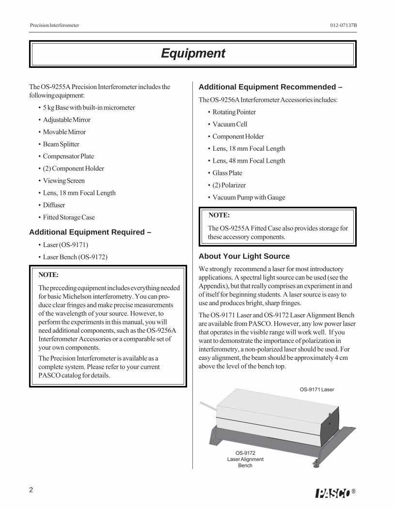
The OS-9171 Laser and OS-9172 Laser Alignment Benchare available from PASCO. However, any low power laserthat operates in the visible range will work well. If youwant to demonstrate the importance of polarization ininterferometry, a non-polarized laser should be used. Foreasy alignment, the beam should be approximately 4 cmabove the level of the bench top.
OS-9171 Laser
OS-9172Laser Alignment
Bench
3
012-07137B Precision Interferometer
�
ViewingScreen
Diffuser
(2) ComponentHolder
MovableMirror
AdjustableMirror
Vacuum Cell
Vacuum Pumpwith Gauge
RotatingPointer
BeamSplitter
CompensatorPlate
ComponentHolder
OS-9255APrecision Interferometer
Lens18 mmFitted Case
(2) Polarizer
Base
OS-9256AInterferometerAccessories
Lens18 mm
Lens48 mm
GlassPlate
Precision Interferometer 012-07137B
4 �
Interference Theory
A beam of light can be modeled as a wave of oscillatingelectric and magnetic fields. When two or more beams oflight meet in space, these fields add according to theprinciple of superposition. That is, at each point in space,the electric and magnetic fields are determined as thevector sum of the fields of the separate beams.
If each beam of light originates from a separate source,there is generally no fixed relationship between the electro-magnetic oscillations in the beams. At any instant in timethere will be points in space where the fields add toproduce a maximum field strength. However, the oscilla-tions of visible light are far faster than the human eye canapprehend. Since there is no fixed relationship betweenthe oscillations, a point at which there is a maximum at oneinstant may have a minimum at the next instant. Thehuman eye averages these results and perceives a uniformintensity of light.
If the beams of light originate from the same source, thereis generally some degree of correlation between thefrequency and phase of the oscillations. At one point inspace the light from the beams may be continually inphase. In this case, the combined field will always be amaximum and a bright spot will be seen. At another pointthe light from the beams may be continually out of phaseand a minima, or dark spot, will be seen.
Thomas Young was one of the first to design a method forproducing such an interference pattern. He allowed asingle, narrow beam of light to fall on two narrow, closelyspaced slits. Opposite the slits he placed a viewing screen.Where the light from the two slits struck the screen, aregular pattern of dark and bright bands appeared. Whenfirst performed, Young’s experiment offered importantevidence for the wave nature of light.
Young’s slits can be used as a simple interferometer. Ifthe spacing between the slits is known, the spacing of themaxima and minima can be used to determine the wave-length of the light. Conversely, if the wavelength of thelight is known, the spacing of the slits could be determinedfrom the interference patterns.
Theory of Operation
The Michelson Interferometer
In 1881, 78 years after Young introduced his two-slitexperiment, A.A. Michelson designed and built an interfer-ometer using a similar principle. Originally Michelsondesigned his interferometer as a means to test for theexistence of the ether, a hypothesized medium in whichlight propagated. Due in part to his efforts, the ether is nolonger considered a viable hypothesis. But beyond this,Michelson’s interferometer has become a widely usedinstrument for measuring the wavelength of light, for usingthe wavelength of a known light source to measureextremely small distances, and for investigating opticalmedia.
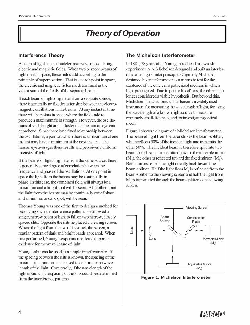
Figure 1 shows a diagram of a Michelson interferometer.The beam of light from the laser strikes the beam-splitter,which reflects 50% of the incident light and transmits theother 50%. The incident beam is therefore split into twobeams; one beam is transmitted toward the movable mirror(M1), the other is reflected toward the fixed mirror (M2).Both mirrors reflect the light directly back toward thebeam-splitter. Half the light from M1 is reflected from thebeam-splitter to the viewing screen and half the light fromM2 is transmitted through the beam-splitter to the viewingscreen.
Adjustable Mirror(M2)
Movable Mirror(M1)
CompensatorPlate
Viewing Screen
BeamSplitter
Lens
Lase
r
Figure 1. Michelson Interferometer
5
012-07137B Precision Interferometer
�
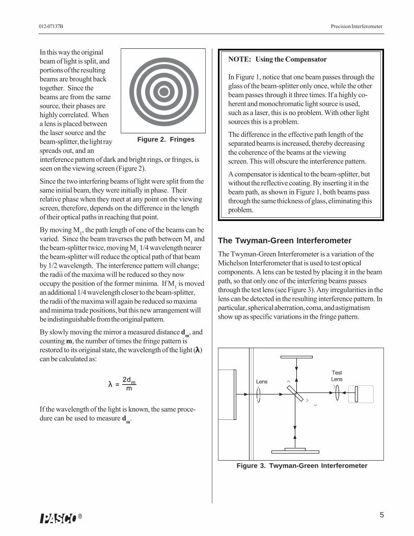
In this way the originalbeam of light is split, andportions of the resultingbeams are brought backtogether. Since thebeams are from the samesource, their phases arehighly correlated. Whena lens is placed betweenthe laser source and thebeam-splitter, the light rayspreads out, and aninterference pattern of dark and bright rings, or fringes, isseen on the viewing screen (Figure 2).
Since the two interfering beams of light were split from thesame initial beam, they were initially in phase. Theirrelative phase when they meet at any point on the viewingscreen, therefore, depends on the difference in the lengthof their optical paths in reaching that point.
By moving M1, the path length of one of the beams can bevaried. Since the beam traverses the path between M1 andthe beam-splitter twice, moving M1 1/4 wavelength nearerthe beam-splitter will reduce the optical path of that beamby 1/2 wavelength. The interference pattern will change;the radii of the maxima will be reduced so they nowoccupy the position of the former minima. If M1 is movedan additional 1/4 wavelength closer to the beam-splitter,the radii of the maxima will again be reduced so maximaand minima trade positions, but this new arrangement willbe indistinguishable from the original pattern.
By slowly moving the mirror a measured distance dm, andcounting m, the number of times the fringe pattern isrestored to its original state, the wavelength of the light (λλλλλ)can be calculated as:
=
2dmm
If the wavelength of the light is known, the same proce-dure can be used to measure dm.
Figure 2. Fringes
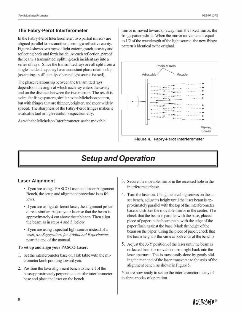
The Twyman-Green Interferometer
The Twyman-Green Interferometer is a variation of theMichelson Interferometer that is used to test opticalcomponents. A lens can be tested by placing it in the beampath, so that only one of the interfering beams passesthrough the test lens (see Figure 3). Any irregularities in thelens can be detected in the resulting interference pattern. Inparticular, spherical aberration, coma, and astigmatismshow up as specific variations in the fringe pattern.
Figure 3. Twyman-Green Interferometer
TestLensLens
NOTE: Using the Compensator
In Figure 1, notice that one beam passes through theglass of the beam-splitter only once, while the otherbeam passes through it three times. If a highly co-herent and monochromatic light source is used,such as a laser, this is no problem. With other lightsources this is a problem.
The difference in the effective path length of theseparated beams is increased, thereby decreasingthe coherence of the beams at the viewingscreen. This will obscure the interference pattern.
A compensator is identical to the beam-splitter, butwithout the reflective coating. By inserting it in thebeam path, as shown in Figure 1, both beams passthrough the same thickness of glass, eliminating thisproblem.
λ
Precision Interferometer 012-07137B
6 �
The Fabry-Perot Interferometer
In the Fabry-Perot Interferometer, two partial mirrors arealigned parallel to one another, forming a reflective cavity.Figure 4 shows two rays of light entering such a cavity andreflecting back and forth inside. At each reflection, part ofthe beam is transmitted, splitting each incident ray into aseries of rays. Since the transmitted rays are all split from asingle incident ray, they have a constant phase relationship(assuming a sufficiently coherent light source is used).
The phase relationship between the transmitted raysdepends on the angle at which each ray enters the cavityand on the distance between the two mirrors. The result isa circular fringe pattern, similar to the Michelson pattern,but with fringes that are thinner, brighter, and more widelyspaced. The sharpness of the Fabry-Perot fringes makes ita valuable tool in high-resolution spectrometry.
As with the Michelson Interferometer, as the movable
Setup and Operation
Laser Alignment
• If you are using a PASCO Laser and Laser AlignmentBench, the setup and alignment procedure is as fol-lows.
• If you are using a different laser, the alignment proce-dure is similar. Adjust your laser so that the beam isapproximately 4 cm above the table top. Then alignthe beam as in steps 4 and 5, below.
• If you are using a spectral light source instead of alaser, see Suggestions for Additional Experiments,near the end of the manual.
To set up and align your PASCO Laser:
1. Set the interferometer base on a lab table with the mi-crometer knob pointing toward you.
2. Position the laser alignment bench to the left of thebase approximately perpendicular to the interferometerbase and place the laser on the bench.
mirror is moved toward or away from the fixed mirror, thefringe pattern shifts. When the mirror movement is equalto 1/2 of the wavelength of the light source, the new fringepattern is identical to the original.
3. Secure the movable mirror in the recessed hole in theinterferometer base.
4. Turn the laser on. Using the leveling screws on the la-ser bench, adjust its height until the laser beam is ap-proximately parallel with the top of the interferometerbase and strikes the movable mirror in the center. (Tocheck that the beam is parallel with the base, place apiece of paper in the beam path, with the edge of thepaper flush against the base. Mark the height of thebeam on the paper. Using the piece of paper, check thatthe beam height is the same at both ends of the bench.)
5. Adjust the X-Y position of the laser until the beam isreflected from the movable mirror right back into thelaser aperture. This is most easily done by gently slid-ing the rear end of the laser transverse to the axis of thealignment bench, as shown in Figure 5.
You are now ready to set up the interferometer in any ofits three modes of operation.
Figure 4. Fabry-Perot Interferometer
Adjustable Movable
Partial Mirrors
ViewingScreen

7
012-07137B Precision Interferometer
�
��������
������������������
�� � � �� �� ��
��
����� ��������������������������������
���
����
����
�
����
����
�
�����������
���������
�������������
������������������������������������
���
NOTE:For ease of installation the placement of the individualcomponents in the various modes is indicated on thelabel.
�� � � �� �� ��
��
����� ��������������������������������
���
����
����
�
����
����
�
�����������
���������
�������������
������������������������������������
Slide the rear of thelaser laterally on thealignment bench untilthe beam is reflectedstraight back into the
laser aperture.
Laser beam
Movablemirror
Figure 5. Aligning the Laser
Michelson Mode
1. Align the laser and interferometer base as previouslydescribed. The laser beam should be approximatelyparallel with the top of the base, should strike the centerof the movable mirror, and should be reflected directlyback into the laser aperture.
2. Mount the adjustable mirror on the interferometer base.Position one component holder in front of the laser.Place the other component holder opposite the adjust-able mirror and attach the viewing screen to its mag-netic backing. See Figure 6.
3. Position the beam-splitter at a 45 degree angle to thelaser beam, within the crop marks, so that the beam isreflected to the fixed mirror. Adjust the angle of thebeam-splitter as needed so that the reflected beam hitsthe fixed mirror near its center.
4. There should now be two sets of bright dots on theviewing screen; one set comes from the fixed mirrorand the other comes from the movable mirror. Eachset of dots should include a bright dot with two or moredots of lesser brightness (due to multiple reflections).Adjust the angle of the beam-splitter again until the twosets of dots are as close together as possible, thentighten the thumbscrew to secure the beam-splitter.
5. Using the thumbscrews on the back of the adjustablemirror, adjust the mirror’s tilt until the two sets of dotson the viewing screen coincide.
6. The compensator is not needed for producing interfer-ence fringes when using a laser light source. However,if you wish to use the compensator, it mounts perpen-dicular to the beam-splitter, as shown.
7. Attach the 18 mm FL lens to the magnetic backing ofthe component holder in front of the laser, as shown,and adjust its position until the diverging beam is cen-tered on the beam-splitter. You should now see circu-lar fringes on the viewing screen. If not, carefully ad-just the tilt of the adjustable mirror until the fringes ap-pear.
8. If you have trouble obtaining fringes, see Trouble-Shooting at the end of this section.
Figure 6. Michelson Mode Setup
Componentholder
Lase
r
Lens18mm FL
Viewing screen
Beamsplitter
Movablemirror
Compensator(optional)
Adjustable mirror
Micrometerknob
Interferometerbase
Thumbscrews
Componentholder
Precision Interferometer 012-07137B
8 �
��������
��������������������
�� � � �� �� ��
��
����� ��������������������������������
���
����
����
�
����
����
�
�����������
���������
�������������
������������������������������������
��� �������
��������
��������������������
�� � � �� �� ��
��
����� ��������������������������������
���
����
����
�
����
����
�
�����������
���������
�������������
������������������������������������
��� �������
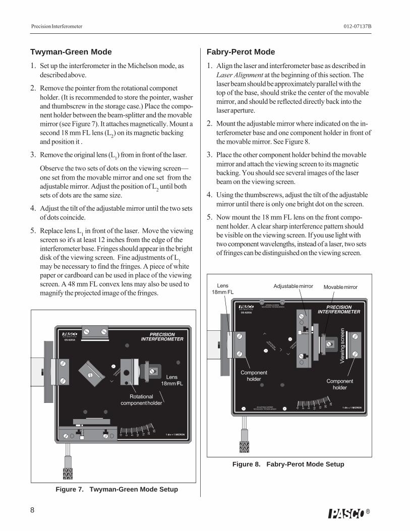
Twyman-Green Mode
1. Set up the interferometer in the Michelson mode, asdescribed above.
2. Remove the pointer from the rotational componetholder. (It is recommended to store the pointer, washerand thumbscrew in the storage case.) Place the compo-nent holder between the beam-splitter and the movablemirror (see Figure 7). It attaches magnetically. Mount asecond 18 mm FL lens (L2) on its magnetic backingand position it .
3. Remove the original lens (L1) from in front of the laser.
Observe the two sets of dots on the viewing screen—one set from the movable mirror and one set from theadjustable mirror. Adjust the position of L2 until bothsets of dots are the same size.
4. Adjust the tilt of the adjustable mirror until the two setsof dots coincide.
5. Replace lens L1 in front of the laser. Move the viewingscreen so it's at least 12 inches from the edge of theinterferometer base. Fringes should appear in the brightdisk of the viewing screen. Fine adjustments of L1may be necessary to find the fringes. A piece of whitepaper or cardboard can be used in place of the viewingscreen. A 48 mm FL convex lens may also be used tomagnify the projected image of the fringes.
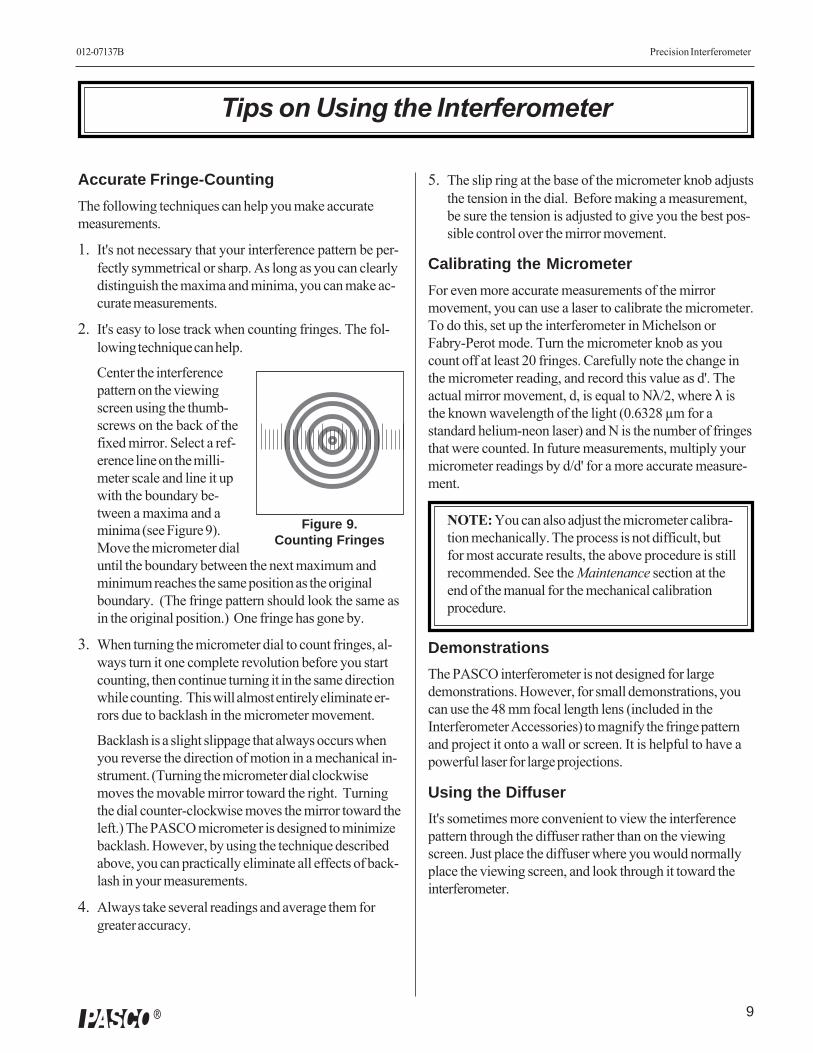
Fabry-Perot Mode
1. Align the laser and interferometer base as described inLaser Alignment at the beginning of this section. Thelaser beam should be approximately parallel with thetop of the base, should strike the center of the movablemirror, and should be reflected directly back into thelaser aperture.
2. Mount the adjustable mirror where indicated on the in-terferometer base and one component holder in front ofthe movable mirror. See Figure 8.
3. Place the other component holder behind the movablemirror and attach the viewing screen to its magneticbacking. You should see several images of the laserbeam on the viewing screen.
4. Using the thumbscrews, adjust the tilt of the adjustablemirror until there is only one bright dot on the screen.
5. Now mount the 18 mm FL lens on the front compo-nent holder. A clear sharp interference pattern shouldbe visible on the viewing screen. If you use light withtwo component wavelengths, instead of a laser, two setsof fringes can be distinguished on the viewing screen.
Lens18mm FL
Figure 7. Twyman-Green Mode Setup
Rotationalcomponent holder
Componentholder
Componentholder
View
ing
scre
en
Adjustable mirror Movable mirrorLens18mm FL
Figure 8. Fabry-Perot Mode Setup
9
012-07137B Precision Interferometer
�
5. The slip ring at the base of the micrometer knob adjuststhe tension in the dial. Before making a measurement,be sure the tension is adjusted to give you the best pos-sible control over the mirror movement.
Calibrating the Micrometer
For even more accurate measurements of the mirrormovement, you can use a laser to calibrate the micrometer.To do this, set up the interferometer in Michelson orFabry-Perot mode. Turn the micrometer knob as youcount off at least 20 fringes. Carefully note the change inthe micrometer reading, and record this value as d'. Theactual mirror movement, d, is equal to Nλ/2, where λ isthe known wavelength of the light (0.6328 µm for astandard helium-neon laser) and N is the number of fringesthat were counted. In future measurements, multiply yourmicrometer readings by d/d' for a more accurate measure-ment.
NOTE: You can also adjust the micrometer calibra-tion mechanically. The process is not difficult, butfor most accurate results, the above procedure is stillrecommended. See the Maintenance section at theend of the manual for the mechanical calibrationprocedure.
Demonstrations
The PASCO interferometer is not designed for largedemonstrations. However, for small demonstrations, youcan use the 48 mm focal length lens (included in theInterferometer Accessories) to magnify the fringe patternand project it onto a wall or screen. It is helpful to have apowerful laser for large projections.
Using the Diffuser
It's sometimes more convenient to view the interferencepattern through the diffuser rather than on the viewingscreen. Just place the diffuser where you would normallyplace the viewing screen, and look through it toward theinterferometer.
Tips on Using the Interferometer
Figure 9.Counting Fringes
Accurate Fringe-Counting
The following techniques can help you make accuratemeasurements.
1. It's not necessary that your interference pattern be per-fectly symmetrical or sharp. As long as you can clearlydistinguish the maxima and minima, you can make ac-curate measurements.
2. It's easy to lose track when counting fringes. The fol-lowing technique can help.
Center the interferencepattern on the viewingscreen using the thumb-screws on the back of thefixed mirror. Select a ref-erence line on the milli-meter scale and line it upwith the boundary be-tween a maxima and aminima (see Figure 9).Move the micrometer dialuntil the boundary between the next maximum andminimum reaches the same position as the originalboundary. (The fringe pattern should look the same asin the original position.) One fringe has gone by.
3. When turning the micrometer dial to count fringes, al-ways turn it one complete revolution before you startcounting, then continue turning it in the same directionwhile counting. This will almost entirely eliminate er-rors due to backlash in the micrometer movement.
Backlash is a slight slippage that always occurs whenyou reverse the direction of motion in a mechanical in-strument. (Turning the micrometer dial clockwisemoves the movable mirror toward the right. Turningthe dial counter-clockwise moves the mirror toward theleft.) The PASCO micrometer is designed to minimizebacklash. However, by using the technique describedabove, you can practically eliminate all effects of back-lash in your measurements.
4. Always take several readings and average them forgreater accuracy.
Precision Interferometer 012-07137B
10 �
Sources of Experimental Error
Backlash— Although PASCO's carefully designed mirrormovement reduces backlash considerably, every mechani-cal system is susceptible to backlash. However, the effectsof backlash can be practically eliminated by using propertechnique when counting fringes (see item 3 under Accu-rate Fringe-Counting, on the previous page).
Mirror Travel— The amount of mirror movement perdial turn of the micrometer is constant to within 1.5%.Most of this error occurs at the extreme ends of themirror’s total possible movement. For very accuratemeasurements, see Calibrating the Micrometer, above,and remember that the mirrors are flat to within 1/4wavelength across their surface.
Troubleshooting
If you have trouble producing a clear set of interferencefringes, consider the following possible sources of diffi-culty:
1. Warm up your Laser— Many lasers vary in intensityand/or polarization as they warm up. To eliminate anypossible fringe or intensity variations, allow the laser towarm up prior to setting up an experiment. (ThePASCO laser should warm up in about 1 hour.)
2. Check your Mirrors— The beam-splitter andmovable mirror are carefully mounted in their bracketsto remain perpendicular to the interferometer basewhen set up. If the brackets are bent slightly out ofalignment, the resulting fringe patterns will be distortedsomewhat. If they are significantly out of alignment, itmay be impossible to obtain fringes.
3. Background Fringes— Reflections from the frontand back surfaces of the mirrors and beam-splitter of-ten cause minor interference patterns in the back-ground of the main fringe pattern. These backgroundpatterns normally do not move when the mirror ismoved, and have no impact on measurements madeusing the main interference pattern.
4. Convection Currents— If the fringe pattern ap-pears to wave or vibrate, check for air currents. Evena slight breeze can effect the fringes.
5. Vibration— Under normal conditions, theinterferometer base and mirror mounts are stableenough to provide a vibration free setup. However, ifthe experiment table is vibrating sufficiently, it willeffect the interference pattern.
IMPORTANT: If the movable mirror doesn'tmove when you turn the micrometer dial, seeMicrometer Spacer Replacement in theMaintenance section at the end of this manual.
Component Specifications
Interferometer Mirrors— 3.175 cm in diameter;0.635 + 0.012 cm thick; flat to 1/4 wavelength on bothsides; coated on one side for 80% reflectance and 20%transmission.
Beam-Splitter— 3.175 cm in diameter; 0.635 + 0.012 cmthick; flat to 1/4 wavelength on both sides; coated on oneside for 50% reflectance and 50% transmission.
Compensator— Identical to the beam-splitter, butuncoated.
Movable Mirror— movement is controlled by themicrometer that is built-into the interferometer base;turning the dial clockwise moves the mirror toward theright (looking from the micrometer side); 25 microns permicrometer dial revolution (±1% near center of move-ment); movement through full distance of travel is linear towithin 1.5%.
IMPORTANT: Avoid touching all mirror surfaces.Minute scratches and dirt can impair the clarity ofinterference images. See the Maintenance section atthe end of this manual for cleaning instructions.
11
012-07137B Precision Interferometer
�
��������
��������������������
�� � � �� �� ��
��
����� ��������������������������������
���
����
����
�
����
����
�
�����������
���������
�������������
������������������������������������
��� �������
Experiment 1: Introduction to Interferometry
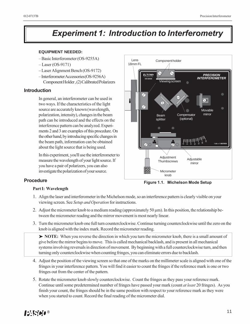
Figure 1.1. Michelson Mode Setup
Component holder
Compensator(optional)
MovablemirrorBeam
splitter
Viewing screen
Adjustablemirror
Micrometerknob
AdjustmentThumbscrews
Lens18mm FL
EQUIPMENT NEEDED:
– Basic Interferometer (OS-9255A)– Laser (OS-9171)– Laser Alignment Bench (OS-9172)– Interferometer Accessories (OS-9256A)
Component Holder , (2) Calibrated Polarizers
IntroductionIn general, an interferometer can be used intwo ways. If the characteristics of the lightsource are accurately known (wavelength,polarization, intensity), changes in the beampath can be introduced and the effects on theinterference pattern can be analyzed. Experi-ments 2 and 3 are examples of this procedure. Onthe other hand, by introducing specific changes inthe beam path, information can be obtainedabout the light source that is being used.
In this experiment, you'll use the interferometer tomeasure the wavelength of your light source. Ifyou have a pair of polarizers, you can alsoinvestigate the polarization of your source.
ProcedurePart I: Wavelength
1. Align the laser and interferometer in the Michelson mode, so an interference pattern is clearly visible on yourviewing screen. See Setup and Operation for instructions.
2. Adjust the micrometer knob to a medium reading (approximately 50 µm). In this position, the relationship be-tween the micrometer reading and the mirror movement is most nearly linear.
3. Turn the micrometer knob one full turn counterclockwise. Continue turning counterclockwise until the zero on theknob is aligned with the index mark. Record the micrometer reading.
➤ NOTE: When you reverse the direction in which you turn the micrometer knob, there is a small amount ofgive before the mirror begins to move. This is called mechanical backlash, and is present in all mechanicalsystems involving reversals in direction of movement. By beginning with a full counterclockwise turn, and thenturning only counterclockwise when counting fringes, you can eliminate errors due to backlash.
4. Adjust the position of the viewing screen so that one of the marks on the millimeter scale is aligned with one of thefringes in your interference pattern. You will find it easier to count the fringes if the reference mark is one or twofringes out from the center of the pattern.
5. Rotate the micrometer knob slowly counterclockwise. Count the fringes as they pass your reference mark.Continue until some predetermined number of fringes have passed your mark (count at least 20 fringes). As youfinish your count, the fringes should be in the same position with respect to your reference mark as they werewhen you started to count. Record the final reading of the micrometer dial.
Precision Interferometer 012-07137B
12 �
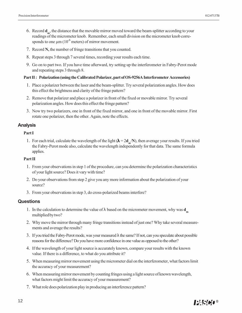
6. Record dm, the distance that the movable mirror moved toward the beam-splitter according to yourreadings of the micrometer knob. Remember, each small division on the micrometer knob corre-sponds to one µm (10-6 meters) of mirror movement.
7. Record N, the number of fringe transitions that you counted.
8. Repeat steps 3 through 7 several times, recording your results each time.
9. Go on to part two. If you have time afterward, try setting up the interferometer in Fabry-Perot modeand repeating steps 3 through 8.
Part II : Polarization (using the Calibrated Polarizer, part of OS-9256A Interferometer Accessories)
1. Place a polarizer between the laser and the beam-splitter. Try several polarization angles. How doesthis effect the brightness and clarity of the fringe pattern?
2. Remove that polarizer and place a polarizer in front of the fixed or movable mirror. Try severalpolarization angles. How does this effect the fringe pattern?
3. Now try two polarizers, one in front of the fixed mirror, and one in front of the movable mirror. Firstrotate one polarizer, then the other. Again, note the effects.
AnalysisPart I
1. For each trial, calculate the wavelength of the light (λλλλλ = 2dm/N), then average your results. If you triedthe Fabry-Perot mode also, calculate the wavelength independently for that data. The same formulaapplies.
Part II
1. From your observations in step 1 of the procedure, can you determine the polarization characteristicsof your light source? Does it vary with time?
2. Do your observations from step 2 give you any more information about the polarization of yoursource?
3. From your observations in step 3, do cross-polarized beams interfere?
Questions1. In the calculation to determine the value of λ based on the micrometer movement, why was dm
multiplied by two?
2. Why move the mirror through many fringe transitions instead of just one? Why take several measure-ments and average the results?
3. If you tried the Fabry-Perot mode, was your measured λ the same? If not, can you speculate about possiblereasons for the difference? Do you have more confidence in one value as opposed to the other?
4. If the wavelength of your light source is accurately known, compare your results with the knownvalue. If there is a difference, to what do you attribute it?
5. When measuring mirror movement using the micrometer dial on the interferometer, what factors limitthe accuracy of your measurement?
6. When measuring mirror movement by counting fringes using a light source of known wavelength,what factors might limit the accuracy of your measurement?
7. What role does polarization play in producing an interference pattern?
13
012-07137B Precision Interferometer
�
Experiment 2: The Index of Refraction of Air
EQUIPMENT NEEDED:
– Basic Interferometer (OS-9255A)– Laser (OS-9171)– Laser Alignment Bench (OS-9172)– Interferometer Accessories (OS-9256A)
Rotational pointer, Vacuum cell, Vacuum pump
IntroductionIn the Michelson interferometer, the characteristics of thefringe pattern depend on the phase relationships betweenthe two interfering beams. There are two ways to changethe phase relationships. One way is to change the distancetraveled by one or both beams (by moving the movablemirror, for example). Another way is to change themedium through which one or both of the beams pass.Either method will influence the interference pattern. Inthis experiment you will use the second method tomeasure the index of refraction for air.
For light of a specific frequency, the wavelength λλλλλ variesaccording to the formula:
λλλλλ = λλλλλo/n;
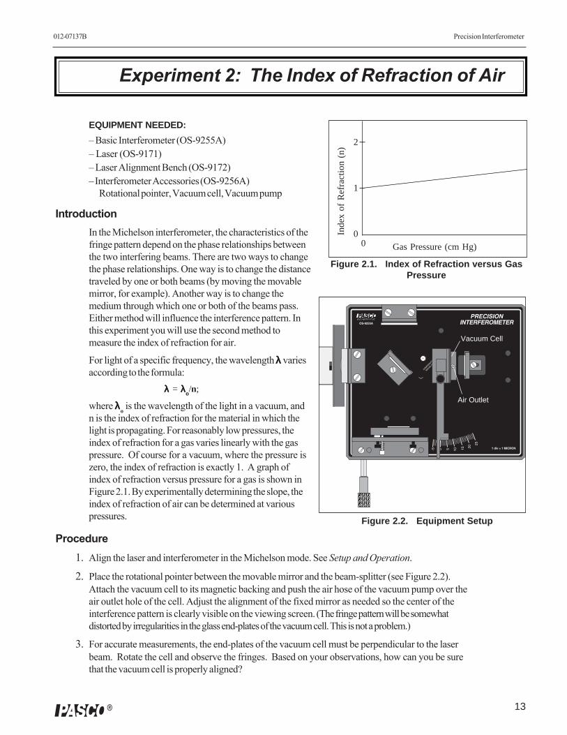
where λλλλλo is the wavelength of the light in a vacuum, andn is the index of refraction for the material in which thelight is propagating. For reasonably low pressures, theindex of refraction for a gas varies linearly with the gaspressure. Of course for a vacuum, where the pressure iszero, the index of refraction is exactly 1. A graph ofindex of refraction versus pressure for a gas is shown inFigure 2.1. By experimentally determining the slope, theindex of refraction of air can be determined at variouspressures.
Procedure1. Align the laser and interferometer in the Michelson mode. See Setup and Operation.
2. Place the rotational pointer between the movable mirror and the beam-splitter (see Figure 2.2).Attach the vacuum cell to its magnetic backing and push the air hose of the vacuum pump over theair outlet hole of the cell. Adjust the alignment of the fixed mirror as needed so the center of theinterference pattern is clearly visible on the viewing screen. (The fringe pattern will be somewhatdistorted by irregularities in the glass end-plates of the vacuum cell. This is not a problem.)
3. For accurate measurements, the end-plates of the vacuum cell must be perpendicular to the laserbeam. Rotate the cell and observe the fringes. Based on your observations, how can you be surethat the vacuum cell is properly aligned?
2
1
00
Inde
x of
Ref
ract
ion
(n)
Gas Pressure (cm Hg)
Figure 2.1. Index of Refraction versus GasPressure
��������
��������������������
�� � � �� �� ��
��
����� ��������������������������������
���
����
����
�
����
����
�
�����������
���������
�������������
������������������������������������
��� �������
Vacuum Cell
Air Outlet
Figure 2.2. Equipment Setup
Precision Interferometer 012-07137B
14 �
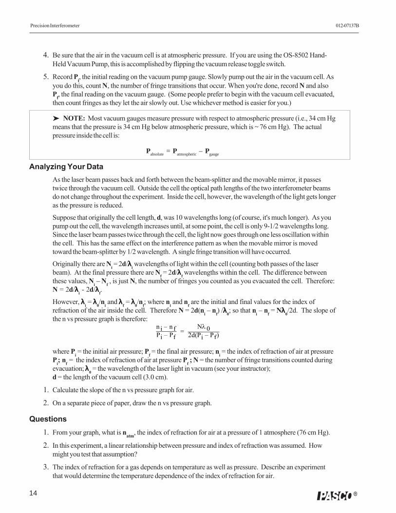
4. Be sure that the air in the vacuum cell is at atmospheric pressure. If you are using the OS-8502 Hand-Held Vacuum Pump, this is accomplished by flipping the vacuum release toggle switch.
5. Record Pi, the initial reading on the vacuum pump gauge. Slowly pump out the air in the vacuum cell. Asyou do this, count N, the number of fringe transitions that occur. When you're done, record N and alsoPf, the final reading on the vacuum gauge. (Some people prefer to begin with the vacuum cell evacuated,then count fringes as they let the air slowly out. Use whichever method is easier for you.)
➤ NOTE: Most vacuum gauges measure pressure with respect to atmospheric pressure (i.e., 34 cm Hgmeans that the pressure is 34 cm Hg below atmospheric pressure, which is ~ 76 cm Hg). The actualpressure inside the cell is:
Pabsolute
= Patmospheric
– Pgauge
Analyzing Your DataAs the laser beam passes back and forth between the beam-splitter and the movable mirror, it passestwice through the vacuum cell. Outside the cell the optical path lengths of the two interferometer beamsdo not change throughout the experiment. Inside the cell, however, the wavelength of the light gets longeras the pressure is reduced.
Suppose that originally the cell length, d, was 10 wavelengths long (of course, it's much longer). As youpump out the cell, the wavelength increases until, at some point, the cell is only 9-1/2 wavelengths long.Since the laser beam passes twice through the cell, the light now goes through one less oscillation withinthe cell. This has the same effect on the interference pattern as when the movable mirror is movedtoward the beam-splitter by 1/2 wavelength. A single fringe transition will have occurred.
Originally there are Ni = 2d/λλλλλi
wavelengths of light within the cell (counting both passes of the laserbeam). At the final pressure there are N
f = 2d/λλλλλf
wavelengths within the cell. The difference betweenthese values, N
i – N
f , is just N, the number of fringes you counted as you evacuated the cell. Therefore:
N = 2d/λλλλλi - 2d/λλλλλf
.
However, λλλλλi = λλλλλ0
/ni and λλλλλf
= λλλλλ0/n
f; where n
i and n
f are the initial and final values for the index of
refraction of the air inside the cell. Therefore N = 2d(ni – n
f) /λλλλλ0
; so that ni – n
f = Nλλλλλ0
/2d. The slope ofthe n vs pressure graph is therefore:
where Pi = the initial air pressure; P
f = the final air pressure; n
i = the index of refraction of air at pressure
Pi; n
f = the index of refraction of air at pressure P
f ; N = the number of fringe transitions counted during
evacuation; λλλλλ0 = the wavelength of the laser light in vacuum (see your instructor);
d = the length of the vacuum cell (3.0 cm).
1. Calculate the slope of the n vs pressure graph for air.
2. On a separate piece of paper, draw the n vs pressure graph.
Questions1. From your graph, what is natm, the index of refraction for air at a pressure of 1 atmosphere (76 cm Hg).
2. In this experiment, a linear relationship between pressure and index of refraction was assumed. Howmight you test that assumption?
3. The index of refraction for a gas depends on temperature as well as pressure. Describe an experimentthat would determine the temperature dependence of the index of refraction for air.
n i – n fPi – Pf
=Nλ0
2d(Pi – Pf)
15
012-07137B Precision Interferometer
�
��������
��������������������
�� � � �� �� ��
��
����� ��������������������������������
���
����
����
�
����
����
�
�����������
���������
�������������
������������������������������������
��� �������
Experiment 3: The Index of Refraction of Glass
EQUIPMENT NEEDED:
– Basic Interferometer (OS-9255A)– Laser (OS-9171)– Laser Alignment Bench (OS-9172)– Interferometer Accessories
Rotating Table, Glass Plate
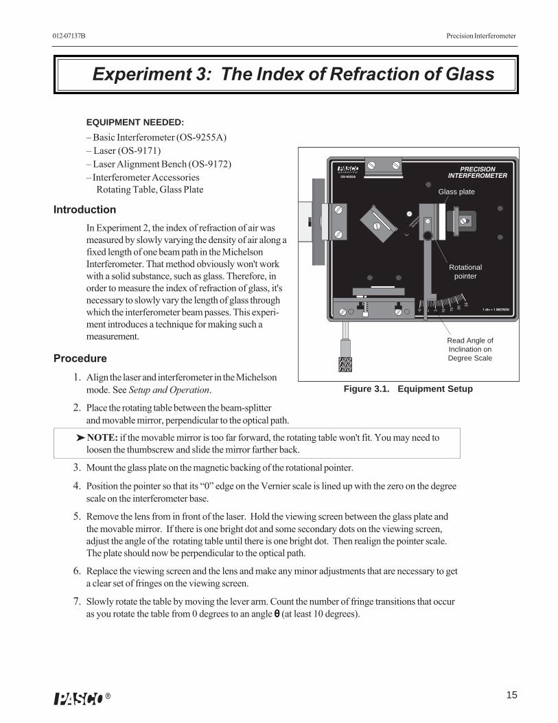
IntroductionIn Experiment 2, the index of refraction of air wasmeasured by slowly varying the density of air along afixed length of one beam path in the MichelsonInterferometer. That method obviously won't workwith a solid substance, such as glass. Therefore, inorder to measure the index of refraction of glass, it'snecessary to slowly vary the length of glass throughwhich the interferometer beam passes. This experi-ment introduces a technique for making such ameasurement.
Procedure1. Align the laser and interferometer in the Michelson
mode. See Setup and Operation.
2. Place the rotating table between the beam-splitterand movable mirror, perpendicular to the optical path.
➤ NOTE: if the movable mirror is too far forward, the rotating table won't fit. You may need toloosen the thumbscrew and slide the mirror farther back.
3. Mount the glass plate on the magnetic backing of the rotational pointer.
4. Position the pointer so that its “0” edge on the Vernier scale is lined up with the zero on the degreescale on the interferometer base.
5. Remove the lens from in front of the laser. Hold the viewing screen between the glass plate andthe movable mirror. If there is one bright dot and some secondary dots on the viewing screen,adjust the angle of the rotating table until there is one bright dot. Then realign the pointer scale.The plate should now be perpendicular to the optical path.
6. Replace the viewing screen and the lens and make any minor adjustments that are necessary to geta clear set of fringes on the viewing screen.
7. Slowly rotate the table by moving the lever arm. Count the number of fringe transitions that occuras you rotate the table from 0 degrees to an angle θθθθθ (at least 10 degrees).
Figure 3.1. Equipment Setup
Read Angle ofInclination onDegree Scale
Rotationalpointer
Glass plate
Precision Interferometer 012-07137B
16 �
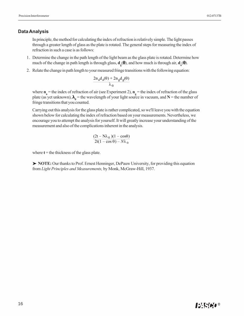
Data AnalysisIn principle, the method for calculating the index of refraction is relatively simple. The light passesthrough a greater length of glass as the plate is rotated. The general steps for measuring the index ofrefraction in such a case is as follows:
1. Determine the change in the path length of the light beam as the glass plate is rotated. Determine howmuch of the change in path length is through glass, dg(θθθθθ), and how much is through air, da(θθθθθ).
2. Relate the change in path length to your measured fringe transitions with the following equation:
where na = the index of refraction of air (see Experiment 2), ng = the index of refraction of the glassplate (as yet unknown), λλλλλ0 = the wavelength of your light source in vacuum, and N = the number offringe transitions that you counted.
Carrying out this analysis for the glass plate is rather complicated, so we'll leave you with the equationshown below for calculating the index of refraction based on your measurements. Nevertheless, weencourage you to attempt the analysis for yourself. It will greatly increase your understanding of themeasurement and also of the complications inherent in the analysis.
where t = the thickness of the glass plate.
➤ NOTE: Our thanks to Prof. Ernest Henninger, DePauw University, for providing this equationfrom Light Principles and Measurements, by Monk, McGraw-Hill, 1937.
2nada(θ) + 2ngdg(θ)λ0
(2t – Nλ0 )(1 – cosθ)2t(1 – cos θ) – Nλ 0
17
012-07137B Precision Interferometer
�
Twyman-Green—
Twyman-Green operation gives students a quick, qualita-tive look at how interferometry can be used to test opticalcomponents. See Twyman-Green Mode in the Setup andOperation section of the manual.
Any distortion of the circular fringe pattern is due tospherical aberration from the test lens. Turn the lens untilit sits at various angles to the optical path and watch thefringe pattern change. Distortion here is due partially toastigmatism from the lens.
Spectral Light Fringes—
Although interferometry is easiest with a laser light source,measurements can be made successfully using any mono-chromatic source of sufficient brightness. However, if alaser is not used, it is generally not possible to project theinterference fringes onto a screen. Instead, the fringes areviewed by looking into the beam-splitter (or into themovable mirror in Fabry-Perot mode).
If you use a spectral light source with spectral lines atseveral different frequencies, it may be necessary to use afilter that blocks all but one of the spectral wavelengths.
Michelson Mode:
➤➤➤➤➤ NOTE:One difficulty when using a non-laser light source inMichelson mode is that the coherence length of thelight is far less with a non-laser source. Because ofthis, the compensator should be used. It mountsmagnetically on the back of the beam-splitter (theside opposite the thumbscrew).
It's also important that the optical paths of the twointerfering beams should be nearly equal. To ensurethat this is the case, set up the interferometer with alaser (if you have one) and adjust the movablemirror position until the fewest possible fringesappear on the screen. (Theoretically, when the beampaths are exactly equal, one big maximum shouldappear that occupies the whole screen. But this isusually not possible to achieve in practice due tooptical imperfections.) Then remove the viewingscreen and replace the laser with the spectral lightsource. If fringes aren't visible when looking into thebeam-splitter, proceed as follows:
a. Tape two thin pieces of wire or thread to the surface ofthe diffuser to form cross-hairs.
b. Place the diffuser between the light source and thebeam-splitter.
c. Adjust the angle of the beam-splitter so that, when look-ing into the beam-splitter, you can see two images ofthe cross-hairs.
d. Adjust the tilt of the fixed mirror until the cross-hairs aresuperimposed. You should be able to see the fringe pat-tern.
Fabry-Perot mode:a. Tape two thin pieces of wire or thread to the surface of
the diffuser to form cross-hairs.
b. Set up the equipment in Fabry-Perot mode, and placethe diffuser between the light source and the fixed mir-ror.
c. Look into the movable mirror from behind. Adjust thetilt of the fixed mirror until the cross-hairs are superim-posed. You should be able to see the fringe pattern.
White Light Fringes—
With careful alignment, the interferometer will producefringes from multi-chromatic or even white light . Theprocedure is the same as for any non-laser source, asdescribed above. However, since it is harder to get a visibleinterference pattern, it is strongly recommended that youfirst set up the interferometer using a laser. Then substituteyour white light source.
Use a Photometer—
Use a photometer, such as PASCO Model OS-9152B, toscan the fringe patterns. You can compare the intensitydistributions in the Michelson and Fabry-Perot modes. Oruse it to more accurately determine polarization effects. Orjust use it as an aid in counting fringes.
Heat Distribution in Air—
With the interferometer in Michelson mode, strike a matchand bring it close to one of the optical paths. Note thedistortions in the fringe pattern. For a more quantitativeapproach, you could construct an air tight cell, and heat thecontents to observe the effects of heat on the index ofrefraction of air.
Suggestions for Additional Experiments

Precision Interferometer 012-07137B
18 �
➤➤➤➤➤ IMPORTANT— The Vacuum Cell is not designed tobe heated.
Index of Refraction for Gases—
Measure the indices of refraction for various gases.Caution: The PASCO Vacuum Chamber is NOT designedto hold positive pressures. You will need to provide yourown gas chamber.
Fabry-Perot Spectroscopy—
The Fabry-Perot mode is customarily used as a high-resolution spectrometer. Very close spectral lines, as inmagnetic splitting, can be resolved much more accuratelythan with any but the highest quality diffraction gratings.
To replace the spacer:
1. Turn the interferometerover, and remove the bot-tom cover.
2. Position the spacer be-tween the two ball bear-ings, as shown in FigureA2. Release the lever, andcheck that the spacer issnugly in place.
3. Replace the bottom panel.
Mirror CareThe mirror and beam-splitter surfaces are precision groundand coated. Dirt or scratches will distort the fringe pattern,so handle all optical surfaces with care. Clean the surfacesoccasionally with lens tissue.
Vacuum CellClean the glass windows on the vacuum chamber occa-sionally with lens tissue.
StorageRotate the Micrometer Knob fully IN before storing theInterferometer.
Micrometer CalibrationThe micrometer is calibrated before it is shipped. How-ever, if recalibration becomes necessary, use the followingprocedure:
1. Turn the interferometerover, and remove the bot-tom cover.
2. Loosen the two screwsshown in Figure A1. Slidethe bearing surface towardthe pivot to increase mir-ror movement per turn ofthe micrometer dial. Slidethe bearing surface awayfrom the pivot to decreasemirror movement per dialturn. Tighten the screwsand replace the bottomcover.
Testing your calibration is most easily performed using alaser light source of known wavelength, as inExperiment 1.
Micrometer Spacer ReplacementIn order to provide extremely fine, backlash-free control ofthe movable mirror, the mechanical linkage between themicrometer and the movable mirror is maintained under astate of spring-loaded compression. This compression alsoholds part of the linkage (a spacer) in place. Under normal use,the spacer will never fall out of position. However, a suddenjolt can jar the spacer and the spring loose. In this case, themicrometer will no longer work, and you'll hear the partsrolling around inside.
Maintenance
Figure A2. SpacerReplacement
Leverarm
Spacer
Loosenscrews and
slide thebearing
surface asrequired.
Figure A1.Calibration
19
012-07137B Precision Interferometer
�
Replacement Parts
Component Part No.
Interferometer Base 003-05137
Adjustable Mirror 003-03957
Beam-Splitter 003-03956
Movable Mirror 003-03955
Component Holder 003-05161
Compensator 003-03958
Interferometer Manual 012-05187
Vacuum Pump OS-8502
Component Part No.
Vacuum Cell 003-05162
Rotational Pointer 003-05160
Fitted Case 650-05178
Viewing Screen 003-05119
Diffuser 003-03941
Polarizer 003-04924
Glass Plate 003-04034
Lens, 18mm FL 003-03814
Lens, 48mm FL 003-03806
Precision Interferometer 012-07137B
20 �
Experiment 1: Introduction to Interferometry
Teacher's Guide
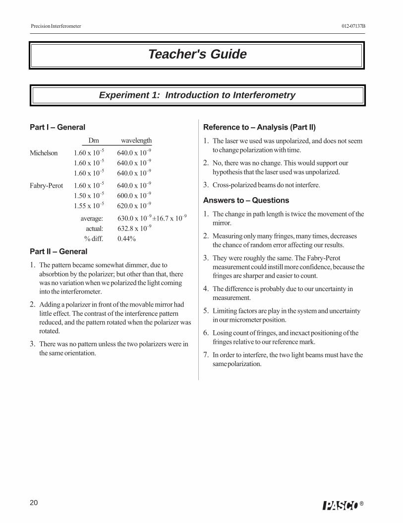
Reference to – Analysis (Part II)1. The laser we used was unpolarized, and does not seem
to change polarization with time.
2. No, there was no change. This would support ourhypothesis that the laser used was unpolarized.
3. Cross-polarized beams do not interfere.
Answers to – Questions1. The change in path length is twice the movement of the
mirror.
2. Measuring only many fringes, many times, decreasesthe chance of random error affecting our results.
3. They were roughly the same. The Fabry-Perotmeasurement could instill more confidence, because thefringes are sharper and easier to count.
4. The difference is probably due to our uncertainty inmeasurement.
5. Limiting factors are play in the system and uncertaintyin our micrometer position.
6. Losing count of fringes, and inexact positioning of thefringes relative to our reference mark.
7. In order to interfere, the two light beams must have thesame polarization.
Part I – GeneralDm wavelength
Michelson 1.60 x 10⁻⁵ 640.0 x 10⁻⁹
1.60 x 10⁻⁵ 640.0 x 10⁻⁹
1.60 x 10⁻⁵ 640.0 x 10⁻⁹
Fabry-Perot 1.60 x 10⁻⁵ 640.0 x 10⁻⁹
1.50 x 10⁻⁵ 600.0 x 10⁻⁹
1.55 x 10⁻⁵ 620.0 x 10⁻⁹
average: 630.0 x 10⁻⁹ ±16.7 x 10⁻⁹
actual: 632.8 x 10⁻⁹
% diff. 0.44%
Part II – General1. The pattern became somewhat dimmer, due to
absorbtion by the polarizer; but other than that, therewas no variation when we polarized the light cominginto the interferometer.
2. Adding a polarizer in front of the movable mirror hadlittle effect. The contrast of the interference patternreduced, and the pattern rotated when the polarizer wasrotated.
3. There was no pattern unless the two polarizers were inthe same orientation.
21
012-07137B Precision Interferometer
�
Experiment 2: The Index of Refraction of Air
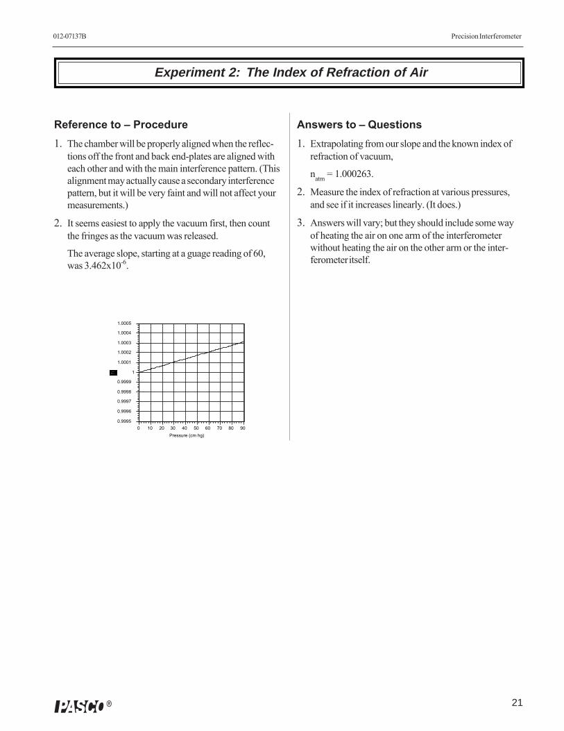
Reference to – Procedure1. The chamber will be properly aligned when the reflec-
tions off the front and back end-plates are aligned witheach other and with the main interference pattern. (Thisalignment may actually cause a secondary interferencepattern, but it will be very faint and will not affect yourmeasurements.)
2. It seems easiest to apply the vacuum first, then countthe fringes as the vacuum was released.
The average slope, starting at a guage reading of 60,was 3.462x10⁻⁶.
0.9995
0.9996
0.9997
0.9998
0.9999
1
1.0001
1.0002
1.0003
1.0004
1.0005
0 10 20 30 40 50 60 70 80 90Pressure (cm hg)
Answers to – Questions1. Extrapolating from our slope and the known index of
refraction of vacuum,
natm = 1.000263.
2. Measure the index of refraction at various pressures,and see if it increases linearly. (It does.)
3. Answers will vary; but they should include some wayof heating the air on one arm of the interferometerwithout heating the air on the other arm or the inter-ferometer itself.
Precision Interferometer 012-07137B
22 �
Experiment 3: The Index of Refraction of Glass
Reference to – Procedure1. The glass plate must be absolutely perpendicular to the
laser for accurate measurement of the index of refrac-tion. When the plate is perpendicular, there will be afaint secondary fringe pattern (Fabry-Perot interferencebetween the front and back surfaces of the plate) vis-ible in the center of the view screen.
2. It is important to measure as large an angle as possible,and measure the angle as carefully as possible.
Reference to – Analysis1. The actual equation, which is derived in Optics of the
Electromagnetic Spectrum, by C.L. Andrews(Prentice-Hall, 1960) is
The second term is negligible for visible wavelengths,and may be ignored.
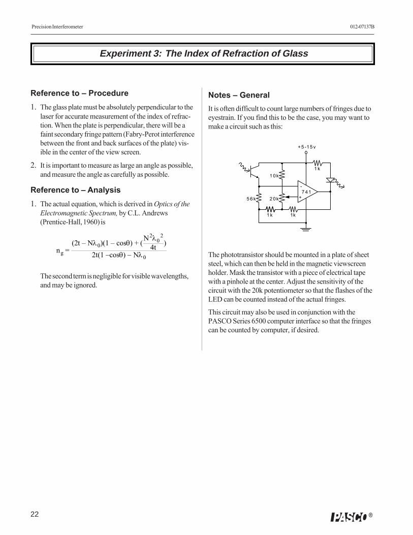
Notes – GeneralIt is often difficult to count large numbers of fringes due toeyestrain. If you find this to be the case, you may want tomake a circuit such as this:
+
-7 41
+5 -15 v
5 6 k 2 0k
1 0k
1 k 1k
1 k
The phototransistor should be mounted in a plate of sheetsteel, which can then be held in the magnetic viewscreenholder. Mask the transistor with a piece of electrical tapewith a pinhole at the center. Adjust the sensitivity of thecircuit with the 20k potentiometer so that the flashes of theLED can be counted instead of the actual fringes.
This circuit may also be used in conjunction with thePASCO Series 6500 computer interface so that the fringescan be counted by computer, if desired.
ng =(2t – Nλ0)(1 – cosθ) + (N2λ0
2
4t )2t(1 –cosθ) – Nλ0

23
012-07137B Precision Interferometer
�
Technical Support
FeedbackIf you have any comments about the product or manual,please let us know. If you have any suggestions onalternate experiments or find a problem in the manual,please tell us. PASCO appreciates any customerfeedback. Your input helps us evaluate and improve ourproduct.
To Reach PASCOFor technical support, call us at 1-800-772-8700(toll-free within the U.S.) or (916) 786-3800.
fax: (916) 786-3292
e-mail: [email protected]
web: www.pasco.com
Contacting Technical SupportBefore you call the PASCO Technical Support staff, itwould be helpful to prepare the following information:
➤ If your problem is with the PASCO apparatus, note:- Title and model number (usually listed on the
label);
- Approximate age of apparatus;
- A detailed description of the problem/sequence ofevents (in case you can’t call PASCO right away, youwon’t lose valuable data);
- If possible, have the apparatus within reach whencalling to facilitate description of individual parts.
➤ If your problem relates to the instruction manual,note:
- Part number and revision (listed by month and yearon the front cover);
- Have the manual at hand to discuss yourquestions.
Precision Interferometer 012-07137B
24 �