Embed Size (px)
Citation preview
CalculiteLEDevo_3in_Pinhole_C3LDP 11/18 page 1 of 5
Project:
Location:
Cat.No:
Type:
Lamps: Qty:
Notes:
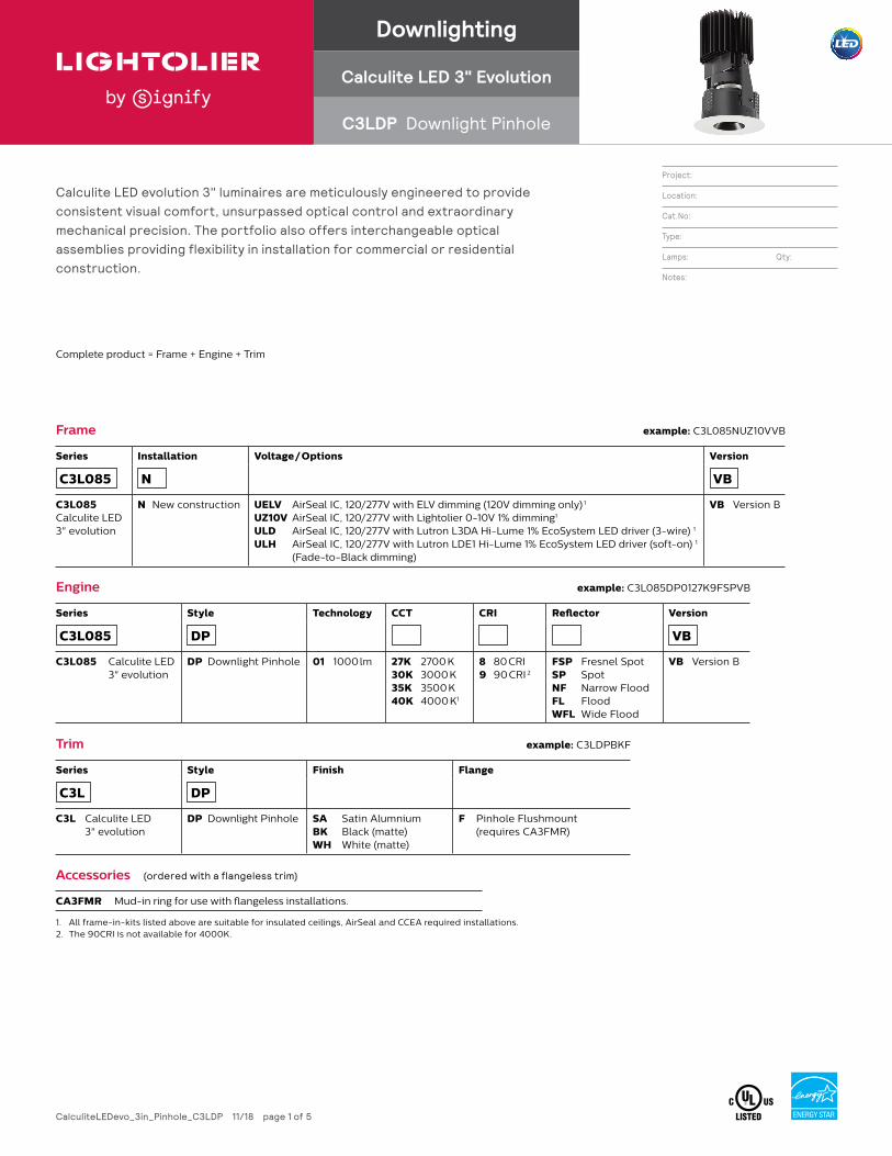
Calculite LED evolution 3" luminaires are meticulously engineered to provide consistent visual comfort, unsurpassed optical control and extraordinary mechanical precision. The portfolio also offers interchangeable optical assemblies providing flexibility in installation for commercial or residential construction.
Frame example: C3L085NUZ10VVB
Series Installation Voltage / Options Version
C3L085 N VB
C3L085 Calculite LED 3" evolution
N New construction UELV AirSeal IC, 120/277V with ELV dimming (120V dimming only) 1
UZ10V AirSeal IC, 120/277V with Lightolier 0-10V 1% dimming1
ULD AirSeal IC, 120/277V with Lutron L3DA Hi-Lume 1% EcoSystem LED driver (3-wire) 1
ULH AirSeal IC, 120/277V with Lutron LDE1 Hi-Lume 1% EcoSystem LED driver (soft-on) 1 (Fade-to-Black dimming)
VB Version B
Engine example: C3L085DP0127K9FSPVB
Series Style Technology CCT CRI Reflector Version
C3L085 DP VB
C3L085 Calculite LED 3" evolution
DP Downlight Pinhole 01 1000 lm 27K 2700 K30K 3000 K35K 3500 K40K 4000 K1
8 80 CRI9 90 CRI 2
FSP Fresnel SpotSP SpotNF Narrow FloodFL FloodWFL Wide Flood
VB Version B
Trim example: C3LDPBKF
Series Style Finish Flange
C3L DP
C3L Calculite LED 3" evolution
DP Downlight Pinhole SA Satin AlumniumBK Black (matte)WH White (matte)
F Pinhole Flushmount (requires CA3FMR)
Accessories (ordered with a flangeless trim)
CA3FMR Mud-in ring for use with flangeless installations.
1. All frame-in-kits listed above are suitable for insulated ceilings, AirSeal and CCEA required installations.2. The 90CRI is not available for 4000K.
Complete product = Frame + Engine + Trim
Downlighting
Calculite LED 3" Evolution
C3LDP Downlight Pinhole
C3LDP Calculite LED 3" EvolutionDownlight Pinhole
CalculiteLEDevo_3in_Pinhole_C3LDP 11/18 page 2 of 5
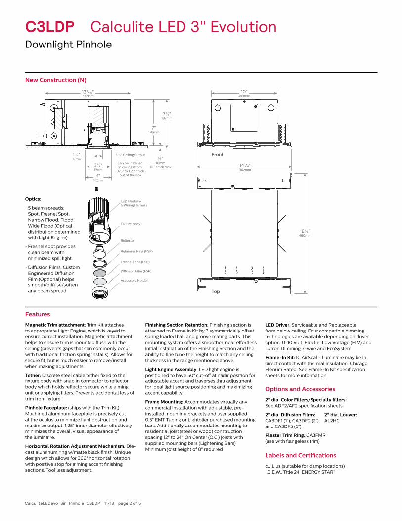
New Construction (N)
10"254mm
14 1⁄4"362mm
Top
Front
13 1⁄16"332mm
⅜"10mm
1¼" thick max
3 ½" Ceiling Cutout
7"178mm
7 ⅜"187mm
1 ¼"32mm
3 ½"89mm
4"102mm
Can be installed in ceilings from
.375" to 1.25" thick out of the box
LED Heatsink& Wiring Harness
Re�ector
Retaining Ring (FSP)
Fresnel Lens (FSP)
Di�usion Film (FSP)
Accessory Holder
Fixture body
18 ⅛"460mm
Optics:
• 5 beam spreads: Spot, Fresnel Spot, Narrow Flood, Flood, Wide Flood (Optical distribution determined with Light Engine).
• Fresnel spot provides clean beam with minimized spill light.
• Diffusion Films: Custom Engineered Diffusion Film (Optional) helps smooth/diffuse/soften any beam spread.
Features
Magnetic Trim attachment: Trim Kit attaches to appropriate Light Engine, which is keyed to ensure correct installation. Magnetic attachment helps to ensure trim is mounted flush with the ceiling (prevents gaps that can commonly occur with traditional friction spring installs). Allows for secure fit, but is much easier to remove/install when making adjustments.
Tether: Discrete steel cable tether fixed to the fixture body with snap in connector to reflector body which holds reflector secure while aiming unit or applying filters. Prevents accidental loss of trim from fixture.
Pinhole Faceplate: (ships with the Trim Kit) Machined aluminum faceplate is precisely cut at the oculus to minimize light obstruction and maximize output. 1.25" inner diameter effectively minimizes the overall visual appearance of the luminaire.
Horizontal Rotation Adjustment Mechanism: Die-cast aluminum ring w/matte black finish. Unique design which allows for 366° horizontal rotation with positive stop for aiming accent finishing sections. Tool less adjustment.
Finishing Section Retention: Finishing section is attached to Frame in Kit by 3 symmetrically offset spring loaded ball and groove mating parts. This mounting system offers a smoother, near effortless initial installation of the Finishing Section and the ability to fine tune the height to match any ceiling thickness in the range mentioned above.
Light Engine Assembly: LED light engine is positioned to have 50° cut-off at nadir position for adjustable accent and traverses thru adjustment for ideal light source positioning and maximizing accent capability.
Frame Mounting: Accommodates virtually any commercial installation with adjustable, pre-installed mounting brackets and user supplied 0.5" EMT Tubing or Lightolier purchased mounting bars. Additionally accommodates mounting to residential joist (steel or wood) construction spacing 12" to 24" On Center (O.C.) joists with supplied mounting bars (Lightening Bars). Minimum joist height of 8" required.
LED Driver: Serviceable and Replaceable from below ceiling. Four compatible dimming technologies are available depending on driver option: 0-10 Volt, Electric Low Voltage (ELV) and Lutron Dimming 3-wire and EcoSystem.
Frame-In Kit: IC AirSeal - Luminaire may be in direct contact with thermal insulation. Chicago Plenum Rated. See Frame-In Kit specification sheets for more information.
Options and Accessories
2" dia. Color Filters/Specialty filters: See ADF2/AF2 specification sheets
2" dia. Diffusion Films: 2" dia. Louver: CA3DF1 (1°), CA3DF2 (2°), AL2HC and CA3DF5 (5°)
Plaster Trim Ring: CA3FMR (use with flangeless trim)
Labels and Certifications
cU.L.us (suitable for damp locations) I.B.E.W., Title 24, ENERGY STAR®
C3LDP Calculite LED 3" EvolutionDownlight Pinhole
CalculiteLEDevo_3in_Pinhole_C3LDP 11/18 page 3 of 5
1. Correlated Color Temperature within specs as defined in ANSI_NEMA_ANSLG C78.377-2008: Specifications for the Chromaticity of Solid State Lighting Products.2. Tested using absolute photometry as specified in LM79: IESNA Approved Method for the Electrical and Photometric Measurements of Solid-State Lighting Products.
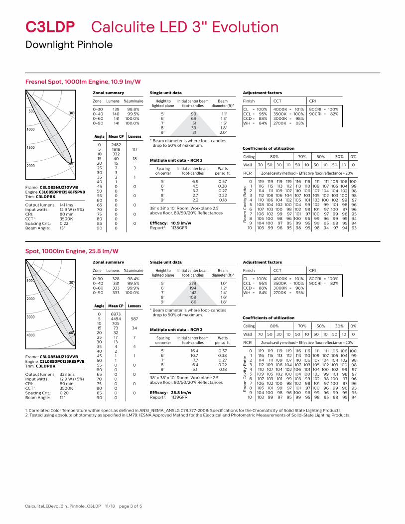
Fresnel Spot, 1000lm Engine, 10.9 lm/W
Spot, 1000lm Engine, 25.8 lm/W
Candella Curves
30°
60°
500
1000
1500
2000 60
0
60
0
Candella Curves
30°
60°
1000
2000
3000
4000 60°
00
°
Frame: C3L085NUZ10VVBEngine: C3L085DP0135K8FSPVBTrim: C3LDPBK
Output lumens: Input watts :CRI:CCT 1: Spacing Crit.:Beam Angle:
141 lms12.9 W (± 5%)80 min3500K0.2213°
Frame: C3L085NUZ10VVBEngine: C3L085DP0135K8SPVBTrim: C3LDPBK
Output lumens: Input watts :CRI:CCT 1: Spacing Crit.:Beam Angle:
333 lms12.9 W (± 5%)80 min3500K0.2012°
Zonal summary
Zone Lumens %Luminaire
0-300-400-600-90
139140141141
98.8%99.5%
100.0%100.0%
Zonal summary
Zone Lumens %Luminaire
0-300-400-600-90
328331333333
98.4%99.5%99.9%
100.0%
Coefficients of utilization
Ceiling 80% 70% 50% 30% 0%
Wall 70 50 30 10 50 10 50 10 50 10 0
RCR Zonal cavity method - Effective floor reflectance = 20%
Ro
om
Ca
vit
y R
ati
o
0123456789
10
119116114112110108107106105104103
119115111
10810610410310210010099
119113
10910610410210099989796
119112
1071041021009897969595
116113110107105104102101
1009998
116110
106103101999897969595
111109107105103102101
100999998
111107104102100999797969594
106105104103102101
10099999897
10610410210099989796959594
10099989897969695949493
Coefficients of utilization
Ceiling 80% 70% 50% 30% 0%
Wall 70 50 30 10 50 10 50 10 50 10 0
RCR Zonal cavity method - Effective floor reflectance = 20%
Ro
om
Ca
vit
y R
ati
o
0123456789
10
119116114112110
109107106105104103
119115111
109107105103102101
10099
119113
109106104102101
100999897
119112
1071041021009998979695
116113110107106104103102101
10099
116110
106103101
1009998979695
111109107105104103102101
1009998
111107104102100999897969695
106105104103102101
100100999998
10610410210099989797969595
10099989897979696959594
Single unit data
Height to lighted plane
Initial center beam foot-candles
Beam diameter (ft)*
5'6'7'8'9'
996951
3931
1.1'1.3'1.5'1.8'2.0'
* Beam diameter is where foot-candles drop to 50% of maximum.
Single unit data
Height to lighted plane
Initial center beam foot-candles
Beam diameter (ft)*
5'6'7'8'9'
27919414210986
1.0'1.2'1.4'1.6'1.8'
* Beam diameter is where foot-candles drop to 50% of maximum.
Multiple unit data - RCR 2
Spacing on center
Initial center beam foot-candles
Watts per sq. ft.
5'6'7'8'9'
6.94.53.22.72.2
0.570.380.270.220.18
38' x 38' x 10' Room, Workplane 2.5' above floor, 80/50/20% Reflectances
Multiple unit data - RCR 2
Spacing on center
Initial center beam foot-candles
Watts per sq. ft.
5'6'7'8'9'
16.410.7
7.76.45.1
0.570.380.270.220.18
38' x 38' x 10' Room, Workplane 2.5' above floor, 80/50/20% Reflectances
Angle Mean CP Lumens
051015202530354045505560657075808590
24821818332401573210000000000
117
18
3
1
0
0
0
0
0
Angle Mean CP Lumens
051015202530354045505560657075808590
6973449470573321713421100000000
587
34
7
4
1
0
0
0
0
Adjustment factors
Finish CCT CRI
CL = 100%CCL = 95%CCD = 88%WH = 84%
4000K = 101%3500K = 100%3000K = 98%2700K = 93%
80CRI = 100%90CRI = 82%
Adjustment factors
Finish CCT CRI
CL = 100%CCL = 95%CCD = 88%WH = 84%
4000K = 101%3500K = 100%3000K = 98%2700K = 93%
80CRI = 100%90CRI = 82%
Efficacy: 10.9 lm/wReport 2: 1138GFR
Efficacy: 25.8 lm/wReport 2: 1139GFR
C3LDP Calculite LED 3" EvolutionDownlight Pinhole
CalculiteLEDevo_3in_Pinhole_C3LDP 11/18 page 4 of 5
1. Correlated Color Temperature within specs as defined in ANSI_NEMA_ANSLG C78.377-2008: Specifications for the Chromaticity of Solid State Lighting Products.2. Tested using absolute photometry as specified in LM79: IESNA Approved Method for the Electrical and Photometric Measurements of Solid-State Lighting Products.
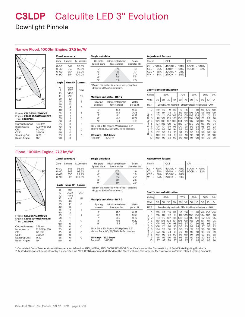
Narrow Flood, 1000lm Engine, 27.5 lm/WCandella Curves
30°
60°
750
1500
2250
3000
050
Frame: C3L085NUZ10VVBEngine: C3L085DP0135K8NFVBTrim: C3LDPBK
Output lumens: Input watts :CRI:CCT 1: Spacing Crit.:Beam Angle:
354 lms12.9 W (± 5%)80 min3500K0.2816°
Zonal summary
Zone Lumens %Luminaire
0-300-400-600-90
349353354354
98.6%99.5%99.9%
100.0%
Coefficients of utilization
Ceiling 80% 70% 50% 30% 0%
Wall 70 50 30 10 50 10 50 10 50 10 0
RCR Zonal cavity method - Effective floor reflectance = 20%
Ro
om
Ca
vit
y R
ati
o
0123456789
10
119116113111
109107105104102101
100
119114111
10710510310199989695
119113
1081051021009896959392
119111
106103100
9796949391
90
116112
10910610410210099979695
116110105102999795949391
90
1111081061041021009998969594
111106103100989695939291
90
106105103102100999897969594
10610310199979594939291
90
1009997969594939291
9089
Single unit data
Height to lighted plane
Initial center beam foot-candles
Beam diameter (ft)*
5'6'7'8'9'
171118876753
1.4'1.7'
2.0'2.2'2.5'
* Beam diameter is where foot-candles drop to 50% of maximum.
Multiple unit data - RCR 2
Spacing on center
Initial center beam foot-candles
Watts per sq. ft.
5'6'7'8'9'
17.311.48.16.85.4
0.570.380.270.220.18
38' x 38' x 10' Room, Workplane 2.5' above floor, 80/50/20% Reflectances
Angle Mean CP Lumens
051015202530354045505560657075808590
426331771408218321513421110000000
246
95
8
3
1
0
0
0
0
Adjustment factors
Finish CCT CRI
CL = 100%CCL = 95%CCD = 88%WH = 84%
4000K = 101%3500K = 100%3000K = 98%2700K = 93%
80CRI = 100%90CRI = 82%
Efficacy: 27.5 lm/wReport 2: 1140GFR
Flood, 1000lm Engine, 27.2 lm/WCandella Curves
30°
60°
500
1000
1500
2000 60
00
0°
00
Frame: C3L085NUZ10VVBEngine: C3L085DP0135K8FLVBTrim: C3LDPBK
Output lumens: Input watts :CRI:CCT 1: Spacing Crit.:Beam Angle:
351 lms12.9 W (± 5%)80 min3500K0.3219°
Zonal summary
Zone Lumens %Luminaire
0-300-400-600-90
346349350351
98.8%99.5%99.9%
100.0%
Coefficients of utilization
Ceiling 80% 70% 50% 30% 0%
Wall 70 50 30 10 50 10 50 10 50 10 0
RCR Zonal cavity method - Effective floor reflectance = 20%
Ro
om
Ca
vit
y R
ati
o
0123456789
10
1191161131101081061041021009897
119114110
1061031019997959392
119112
107103100989694929089
119111
10510198959391
908887
116112
1081051021009896959392
116109104100
97959391
908887
111108105103101999795949291
1111061029996949291898887
10610410210199979694939290
106103100
9795939290898886
10098969593929089888786
Single unit data
Height to lighted plane
Initial center beam foot-candles
Beam diameter (ft)*
5'6'7'8'9'
12788655039
1.6'1.9'2.2'2.6'2.9'
* Beam diameter is where foot-candles drop to 50% of maximum.
Multiple unit data - RCR 2
Spacing on center
Initial center beam foot-candles
Watts per sq. ft.
5'6'7'8'9'
17.011.28.06.65.3
0.570.380.270.220.18
38' x 38' x 10' Room, Workplane 2.5' above floor, 80/50/20% Reflectances
Angle Mean CP Lumens
051015202530354045505560657075808590
31812522144441548158421110000000
207
131
8
2
1
0
0
0
0
Adjustment factors
Finish CCT CRI
CL = 100%CCL = 95%CCD = 88%WH = 84%
4000K = 101%3500K = 100%3000K = 98%2700K = 93%
80CRI = 100%90CRI = 82%
Efficacy: 27.2 lm/wReport 2: 1141GFR
© 2019 Signify Holding. All rights reserved. This document may be subject to change. No representation or warranty as to the accuracy or completeness of the information included herein is given and any liability for any action in reliance thereon is disclaimed. All trademarks are owned by Signify Holding or their respective owners.
Signify North America Corporation 200 Franklin Square Drive, Somerset, NJ 08873 Telephone 855-486-2216
Signify Canada Ltd. 281 Hillmount Road, Markham, ON, Canada L6C 2S3 Telephone 800-668-9008
www.lightolier.com
C3LDP Calculite LED 3" EvolutionDownlight Pinhole
CalculiteLEDevo_3in_Pinhole_C3LDP 11/18 page 5 of 5
1. Correlated Color Temperature within specs as defined in ANSI_NEMA_ANSLG C78.377-2008: Specifications for the Chromaticity of Solid State Lighting Products.2. Tested using absolute photometry as specified in LM79: IESNA Approved Method for the Electrical and Photometric Measurements of Solid-State Lighting Products.
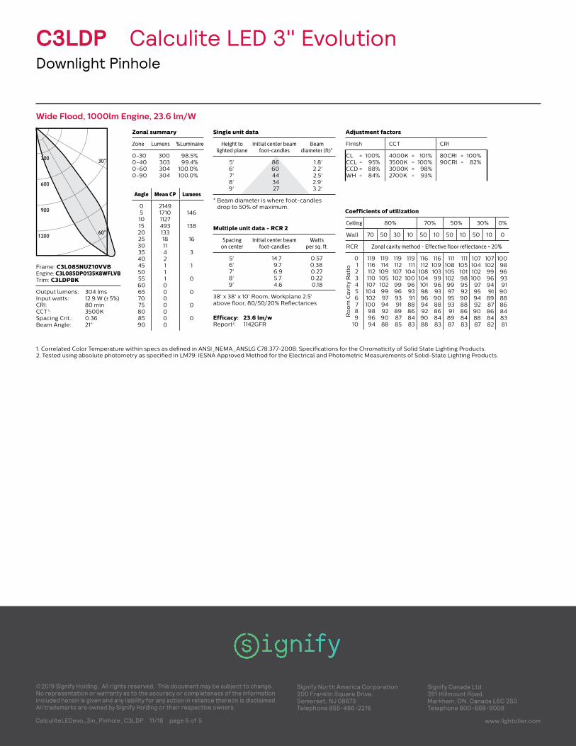
Wide Flood, 1000lm Engine, 23.6 lm/WCandella Curves
30°
60°
300
600
900
1200 60°
30030
Frame: C3L085NUZ10VVBEngine: C3L085DP0135K8WFLVBTrim: C3LDPBK
Output lumens: Input watts :CRI:CCT 1: Spacing Crit.:Beam Angle:
304 lms12.9 W (± 5%)80 min3500K0.3621°
Zonal summary
Zone Lumens %Luminaire
0-300-400-600-90
300303304304
98.5%99.4%
100.0%100.0%
Coefficients of utilization
Ceiling 80% 70% 50% 30% 0%
Wall 70 50 30 10 50 10 50 10 50 10 0
RCR Zonal cavity method - Effective floor reflectance = 20%
Ro
om
Ca
vit
y R
ati
o
0123456789
10
119116112110107104102100989694
119114
109105102999794929088
119112
10710299969391898785
119111
10410096939188868483
116112
108104101989694929088
1161091039996939088868483
11110810510299979593918987
1111051019895929088868483
107104102100
97959492908887
107102999694918987868482
10098969391
908886848381
Single unit data
Height to lighted plane
Initial center beam foot-candles
Beam diameter (ft)*
5'6'7'8'9'
8660443427
1.8'2.2'2.5'2.9'3.2'
* Beam diameter is where foot-candles drop to 50% of maximum.
Multiple unit data - RCR 2
Spacing on center
Initial center beam foot-candles
Watts per sq. ft.
5'6'7'8'9'
14.79.76.95.74.6
0.570.380.270.220.18
38' x 38' x 10' Room, Workplane 2.5' above floor, 80/50/20% Reflectances
Angle Mean CP Lumens
051015202530354045505560657075808590
2149171011274931331811421110000000
146
138
16
3
1
0
0
0
0
Adjustment factors
Finish CCT CRI
CL = 100%CCL = 95%CCD = 88%WH = 84%
4000K = 101%3500K = 100%3000K = 98%2700K = 93%
80CRI = 100%90CRI = 82%
Efficacy: 23.6 lm/wReport 2: 1142GFR