Embed Size (px)
DESCRIPTION
g
Citation preview
ANSYSANSYS Linear Elastic
Fracture MechanicsFracture Mechanics Example

LEFM Example
S S h h bili f li l i f ANSYS has the ability to perform linear elastic fracture mechanics (LEFM) using several approaches.
— LEFM uses derived elasticity solutions to determine the stress intensity factor K at a crack tipintensity factor KI at a crack tip.
— KI can be compared to the material fracture toughness to determine if the crack will propagate.
ANSYS also has the ability with the J-integral feature to predict crack behavior in the presence of plasticity.
This feature is not presented here— This feature is not presented here.

LEFM Example
h h h b f d i S S i l d The approaches that can be performed in ANSYS include:— Direct method – Substitute near-crack element stress and
locations directly into the near-crack elasticity solution to estimate Kestimate KI.
— Use special quarter-point crack elements and KCALC command to predict KI.
— Use J-integral method to predict J from path integration around— Use J integral method to predict J from path integration around crack tip, then use relationship between J and KI to determine KI.
— Crack opening displacement approach to relate the relative displacement of the crack faces to KI.
Several of these methods are demonstrated and compared to theoretical results.

LEFM Example
i bl Demonstration problem: — Prediction and comparison of KI of compact specimen using the
following methods:H d l l ti• Hand calculation.
• ANSYS special crack tip elements.• ANSYS J-integral method.• ANSYS direct method.ANSYS direct method.

LEFM Example
D t ti bl H d l l ti Demonstration problem: Hand calculation. — From fracture mechanics text, KI for a compact specimen is given
as:
WBKaf I
432
23 60.572.1432.1364.4886.0
2
Wa
Wa
Wa
Wa
a
Wa
Waf
PWf I
1
Wa
1.25 W
B = 1 in
a = 1 in
W = 2 inKI = 227.7 psi-in1/2
5 W = 2 in
P = 33.3 lb

LEFM Example
D t ti bl ANSYS i l k ti l t Demonstration problem: ANSYS special crack tip elements. — 2D plane strain mesh.— KSCON command used to automatically create local crack tip mesh
with quarter point nodeswith quarter-point nodes.— Half specimen modeled using symmetry boundary conditions.
Crack tipCrack tipCrack face
Symmetry boundary

LEFM Example
D t ti bl ANSYS i l k ti l t Demonstration problem: ANSYS special crack tip elements. — KCALC command used with quarter-point elements to determine
KI.
1/2KI = 225.6 psi-in1/2

LEFM Example
D t ti bl ANSYS J i t l th d Demonstration problem: ANSYS J-integral method. — CINT commands used to define crack tip node and request
number of contours to use (10).Same model as before but special crack tip elements are not— Same model as before, but special crack tip elements are not required.
— Paths are created automatically around the crack tip, using the next available row of elements.
Path 7 of 10Path 7 of 10
Crack tipCrack tipCrack face

LEFM Example
D t ti bl ANSYS J i t l th d Demonstration problem: ANSYS J-integral method. — Printed J-integral values for 10 contours:
— Plotted J-integral values for 10 contours:
J = 0.00154 lb/in

LEFM Example
D t ti bl ANSYS J i t l th d Demonstration problem: ANSYS J-integral method. — Relating J and KI for plane strain, assuming no plasticity:
K 22 1 E
KJ I22 1
K = 225 3 psi-in1/2J = 0.00154 lb/in
KI = 225.3 psi-in1/2E = 30 x 106 psi
= 0.3
LEFM Example
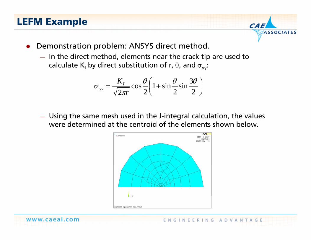
D t ti bl ANSYS di t th d Demonstration problem: ANSYS direct method. — In the direct method, elements near the crack tip are used to
calculate KI by direct substitution of r, , and yy:
23sin
2sin1
2cos
2
rKI
yy
— Using the same mesh used in the J-integral calculation, the values were determined at the centroid of the elements shown below.
LEFM Example
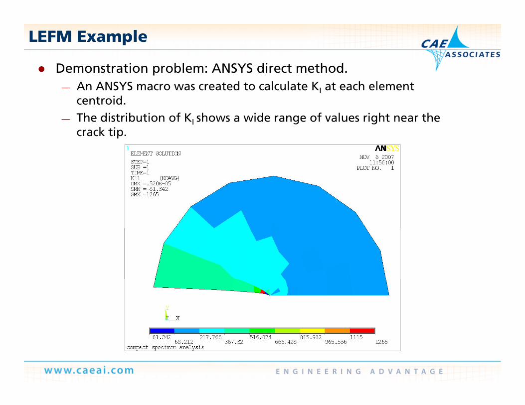
Demonstration problem: ANSYS direct method. p— An ANSYS macro was created to calculate KI at each element
centroid.— The distribution of KI shows a wide range of values right near the
crack tip.
LEFM Example
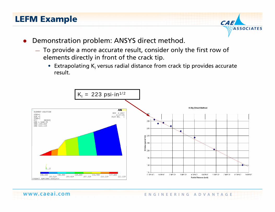
D t ti bl ANSYS di t th d Demonstration problem: ANSYS direct method. — To provide a more accurate result, consider only the first row of
elements directly in front of the crack tip.• Extrapolating K versus radial distance from crack tip provides accurate• Extrapolating KI versus radial distance from crack tip provides accurate
result.
K 223 i i 1/2KI = 223 psi-in1/2