Embed Size (px)
Citation preview

Low Budget Fracture MechanicsLaboratory*
J. CONGLETONMaterials Division, Department of Mechanical, Materials and Manufacturing Engineering,University of Newcastle, NE1 7RU, England, UK.C. C. CHAMADepartment of Metallurgy, School of Mines, University of Zambia, PO Box 32379, Lusaka, Zambia.
Experiments are described that can be used to demonstrate various aspects of linear elastic fracturemechanics. These have been designed to run with minimal capital investment, specimen preparationand recurrent costs. Some of the experiments can be extended for use as topics for student projects.
AUTHOR QUESTIONNAIRE
1. This paper describes new training tools orlaboratory experiments in fracture mechanics.
2. This is a senior course in materials offered bythe University of Zambia: MM422 PhysicalMetallurgy II.
3. The course involves fourth-year students in afive-year undergraduate degree programme.
4. Methods for enhancing the teaching of fracturemechanics under conditions of restricted capitalinvestment and running costs for laboratorywork are a feature of this paper.
5. The material, as laboratory practicals, supple-ment the lectures on topics dealing with fracturemechanics such as stress intensity factor deter-mination.
6. Several research publications and texts, such asFracture Mechanics by J. Knott and P. Withey,are recommended supporting documentation.
7. The concepts have been fully tested and thestudents now appreciate the importance ofusing materials at conditions that do notpromote fracture.
8. The paper shows that the basic concepts offracture mechanics can be demonstrated byusing simple equipment.
INTRODUCTION
A SIGNIFICANT change in engineering design inthe last forty years is the growing awareness ofdefect tolerance in structures as opposed to incor-porating large factors of safety in design calcula-tions. All metallic components will contain somedefects and many will contain actual cracks. Thisdoes not necessarily prevent their use but it isdesirable to know what size of defect can betolerated in a structure and what the expected life
of a defect-containing structure will be. Addition-ally, cracks may form during the life of a structure.The most likely reasons for this are fatigue, corro-sion fatigue and stress corrosion cracking. Theseproblems, and those associated with life-extensionarguments and/or the setting of inspection sche-dules, can be solved with the aid of linear elasticfracture mechanics (LEFM) and elastic-plasticfracture mechanics (EPFM). Appropriate pro-cedures have been developed but the test methodsinvolved tend to be expensive to perform. The aimof this paper is to illustrate that the essentials ofLEFM and EPFM can be demonstrated usingsimple, inexpensive experiments and equipment.The particular experiments described below weredevised for a fourth-year laboratory class in theSchool of Mines, University of Zambia (UNZA),Lusaka using a Hounsfield tensometer and variousrigs manufactured at UNZA. The specimens werein most cases of simple design to minimize work-shop time and material procurement.
BACKGROUND EDUCATIONALCONSIDERATIONS
University engineering education in Zambiacommenced in the late 1960s when the Universityof Zambia (UNZA) was established. Initially, thefaculty of engineering housed Mechanical, Elec-trical and Civil Engineering Departments. Coursesin metallurgy were introduced in 1973 and agri-cultural engineering and surveying in the 1980s.The initial metallurgy course at UNZA was biasedtowards extractive metallurgy with little coverageof physical metallurgy and materials science.Fracture mechanics and corrosion were notcovered at all in any of the programmes. Materialsscience has been taught only as a small componentof mechanical engineering and metallurgy courses.
Developments in Zambia connected with thechanges in dominance of copper mining as the* Accepted 7 October 1999.
56
Int. J. Engng Ed. Vol. 16, No. 1, pp. 56±67, 2000 0949-149X/91 $3.00+0.00Printed in Great Britain. # 2000 TEMPUS Publications.
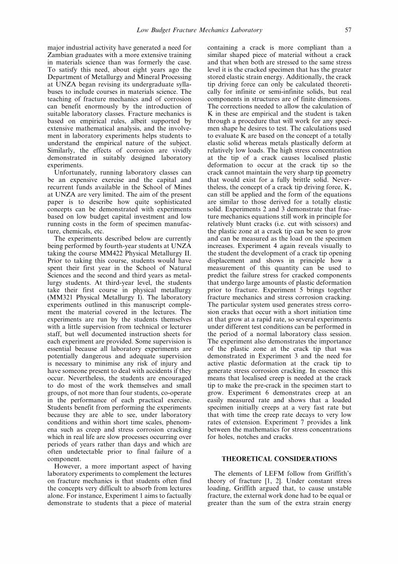
major industrial activity have generated a need forZambian graduates with a more extensive trainingin materials science than was formerly the case.To satisfy this need, about eight years ago theDepartment of Metallurgy and Mineral Processingat UNZA began revising its undergraduate sylla-buses to include courses in materials science. Theteaching of fracture mechanics and of corrosioncan benefit enormously by the introduction ofsuitable laboratory classes. Fracture mechanics isbased on empirical rules, albeit supported byextensive mathematical analysis, and the involve-ment in laboratory experiments helps students tounderstand the empirical nature of the subject.Similarly, the effects of corrosion are vividlydemonstrated in suitably designed laboratoryexperiments.
Unfortunately, running laboratory classes canbe an expensive exercise and the capital andrecurrent funds available in the School of Minesat UNZA are very limited. The aim of the presentpaper is to describe how quite sophisticatedconcepts can be demonstrated with experimentsbased on low budget capital investment and lowrunning costs in the form of specimen manufac-ture, chemicals, etc.
The experiments described below are currentlybeing performed by fourth-year students at UNZAtaking the course MM422 Physical Metallurgy II.Prior to taking this course, students would havespent their first year in the School of NaturalSciences and the second and third years as metal-lurgy students. At third-year level, the studentstake their first course in physical metallurgy(MM321 Physical Metallurgy I). The laboratoryexperiments outlined in this manuscript comple-ment the material covered in the lectures. Theexperiments are run by the students themselveswith a little supervision from technical or lecturerstaff, but well documented instruction sheets foreach experiment are provided. Some supervision isessential because all laboratory experiments arepotentially dangerous and adequate supervisionis necessary to minimise any risk of injury andhave someone present to deal with accidents if theyoccur. Nevertheless, the students are encouragedto do most of the work themselves and smallgroups, of not more than four students, co-operatein the performance of each practical exercise.Students benefit from performing the experimentsbecause they are able to see, under laboratoryconditions and within short time scales, phenom-ena such as creep and stress corrosion crackingwhich in real life are slow processes occurring overperiods of years rather than days and which areoften undetectable prior to final failure of acomponent.
However, a more important aspect of havinglaboratory experiments to complement the lectureson fracture mechanics is that students often findthe concepts very difficult to absorb from lecturesalone. For instance, Experiment 1 aims to factuallydemonstrate to students that a piece of material
containing a crack is more compliant than asimilar shaped piece of material without a crackand that when both are stressed to the same stresslevel it is the cracked specimen that has the greaterstored elastic strain energy. Additionally, the cracktip driving force can only be calculated theoreti-cally for infinite or semi-infinite solids, but realcomponents in structures are of finite dimensions.The corrections needed to allow the calculation ofK in these are empirical and the student is takenthrough a procedure that will work for any speci-men shape he desires to test. The calculations usedto evaluate K are based on the concept of a totallyelastic solid whereas metals plastically deform atrelatively low loads. The high stress concentrationat the tip of a crack causes localised plasticdeformation to occur at the crack tip so thecrack cannot maintain the very sharp tip geometrythat would exist for a fully brittle solid. Never-theless, the concept of a crack tip driving force, K,can still be applied and the form of the equationsare similar to those derived for a totally elasticsolid. Experiments 2 and 3 demonstrate that frac-ture mechanics equations still work in principle forrelatively blunt cracks (i.e. cut with scissors) andthe plastic zone at a crack tip can be seen to growand can be measured as the load on the specimenincreases. Experiment 4 again reveals visually tothe student the development of a crack tip openingdisplacement and shows in principle how ameasurement of this quantity can be used topredict the failure stress for cracked componentsthat undergo large amounts of plastic deformationprior to fracture. Experiment 5 brings togetherfracture mechanics and stress corrosion cracking.The particular system used generates stress corro-sion cracks that occur with a short initiation timeat that grow at a rapid rate, so several experimentsunder different test conditions can be performed inthe period of a normal laboratory class session.The experiment also demonstrates the importanceof the plastic zone at the crack tip that wasdemonstrated in Experiment 3 and the need foractive plastic deformation at the crack tip togenerate stress corrosion cracking. In essence thismeans that localised creep is needed at the cracktip to make the pre-crack in the specimen start togrow. Experiment 6 demonstrates creep at aneasily measured rate and shows that a loadedspecimen initially creeps at a very fast rate butthat with time the creep rate decays to very lowrates of extension. Experiment 7 provides a linkbetween the mathematics for stress concentrationsfor holes, notches and cracks.
THEORETICAL CONSIDERATIONS
The elements of LEFM follow from Griffith'stheory of fracture [1, 2]. Under constant stressloading, Griffith argued that, to cause unstablefracture, the external work done had to be equal orgreater than the sum of the extra strain energy
Low Budget Fracture Mechanics Laboratory 57
stored due to an extension of crack length `da' andthe work needed to generate the new surfaces, i.e.4 da. The intrinsic surface energy used by Griffithwas modified later by Orowan [3] and by Irwin [4]to include the total work done in creating the newsurface. This effective surface energy, 0, is amaterial property only if certain dimensionalconstraints are applied to the specimens used tomeasure it. LEFM and EPFM have evolvedexperimentally and provide guidelines for theeffective assessment of the strengths of defect-containing components. These subjects are stillevolving, as illustrated by the modifications thathave been incorporated into the R6 fracture assess-ment procedure [5, 6].
Griffiths equation states that the fracture stress,�f, for a thin plate containing a `2a' long throughcrack is given by:
�f � 2E
�a
� �1=2
where E is Young's Modulus and is the solidsurface energy. This can be rearranged as:
�1=2�f a1=2 � �2E �1=2
The first step towards LEFM is to show that K =�1/2�a1/2 = (EG)1/2, where G is the strain energyrelease rate. Subsequently, it is necessary to showthat K is dependent upon the ratio defect length/specimen width, (a/W), and the crack shape. Thesetwo correction factors arise from the calculation ofthe elastic stresses at crack tips in finite dimensionspecimens or structures. The K for unstable crackgrowth, KQ, varies with material thickness. This isbecause yield in a ductile material occurs at a lowerapplied load under uniaxial stress than under
biaxial or triaxial tensile stresses. Localized defor-mation at the crack tip accompanies fracture innon-brittle materials and is the major componentof the work of fracture. The larger plastic zone thatforms under biaxial tension compared to triaxialtension increases the toughness of thin sectionmaterial providing that the material thickness isnot less than the crack tip plastic zone diameter.
The following experiments were used to demon-strate various aspects of fracture mechanics.
Experiment 1: Compliance and work of fractureThis experiment is to illustrate how the K for a
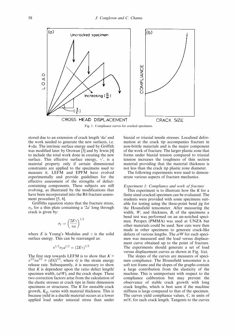
finite sized cracked specimen can be evaluated. Thestudents were provided with some specimens suit-able for testing using the three-point bend jig forthe Hounsfield tensometer. After measuring thewidth, W, and thickness, B, of the specimens abend test was performed on an un-notched speci-men. Perspex (PMMA) was used at UNZA butother materials could be used. Saw cuts were thenmade in other specimens to generate crack-likedefects of various lengths. The a/W for each speci-men was measured and the load versus displace-ment curve obtained up to the point of fracture.The experiments should generate a set of loadversus displacement curves as shown in Fig. 1(a).
The slopes of the curves are measures of speci-men compliance. The Hounsfield tensometer is asoft test frame and the slopes of the graphs containa large contribution from the elasticity of themachine. This is unimportant with respect to thecompliance calibration but may prevent theobservance of stable crack growth with longcrack lengths, which is best seen if the machinestiffness is large compared to that of the specimen.The curves yield compliance values, C, in units ofm/N, for each crack length. Tangents to the curves
Fig. 1. Compliance curves for cracked specimens.
J. Congleton and C. Chama58
of C versus `a' at various `a' values, Fig. 1(b), givedC/da values and the K calibration can be obtainedas follows. Let:
Ut � total elastic strain energy in the system.Um � stored strain energy in the machine.Us � stored strain energy for an un-cracked
specimen.Uc � extra strain energy due to presence of crack.
i.e. Ut � Um �Us �Uc
dUt
da� dUc
da�1�
Griffith showed that (dUc/da)�a is numericallyequal to 2 0B�a, where 0 = effective surfaceenergy and B is specimen thickness. Also, Ut =Px/2, where P = load and x = cross head displace-ment. But C = x/P; therefore Ut = CP2/2 and:
�dUt=da��a � �dUc=da��a
� �P2=2��dC=da��a � 2 0B�a:
Also, K 2 � EG � 2E 0. Therefore:
�P2=2��dC=da��a � K2B�a=E
i.e. K � ���p �EP2=2B��dC=da��
Thus, substitution of a `P' and an `a' value willallow the calculation of K for the appropriate dC/da, which is a specific K for this specimen geome-try. E for perspex is about 4.38 GPa.
However, the K for a three-point bend specimenwith a/W close to zero is given by Ko = 6M
���p �a�/(BW2), where M is the bending moment. Thus, for
any chosen a, or a/W, the ratio K/Ko can beevaluated and a graph of this ratio against a/W iscalled the K calibration for the specimen geometryunder consideration.
It will be found that even very crude measure-ments on specimens with saw cut grooves yield a Kcalibration that is in reasonable agreement withdata obtained by more exact procedures. Also, thestudents can use their measured fracture strengthsand conventional LEFM equations to obtain Kc
values that agree reasonable well with those calcu-lated using dC/da and the Young's modulus for thematerial under test.
If the testing machine is hard enough to givestable crack growth when the crack lengths arelong, the area under the load displacement curvecan be used to estimate the work of fracture. Thearea under the graph that relates to the work offracture, in appropriate units, divided by the areaof new surface, 2B(W±a), gives an alternativeestimate of 0, and 2E 0 � EG � K2.
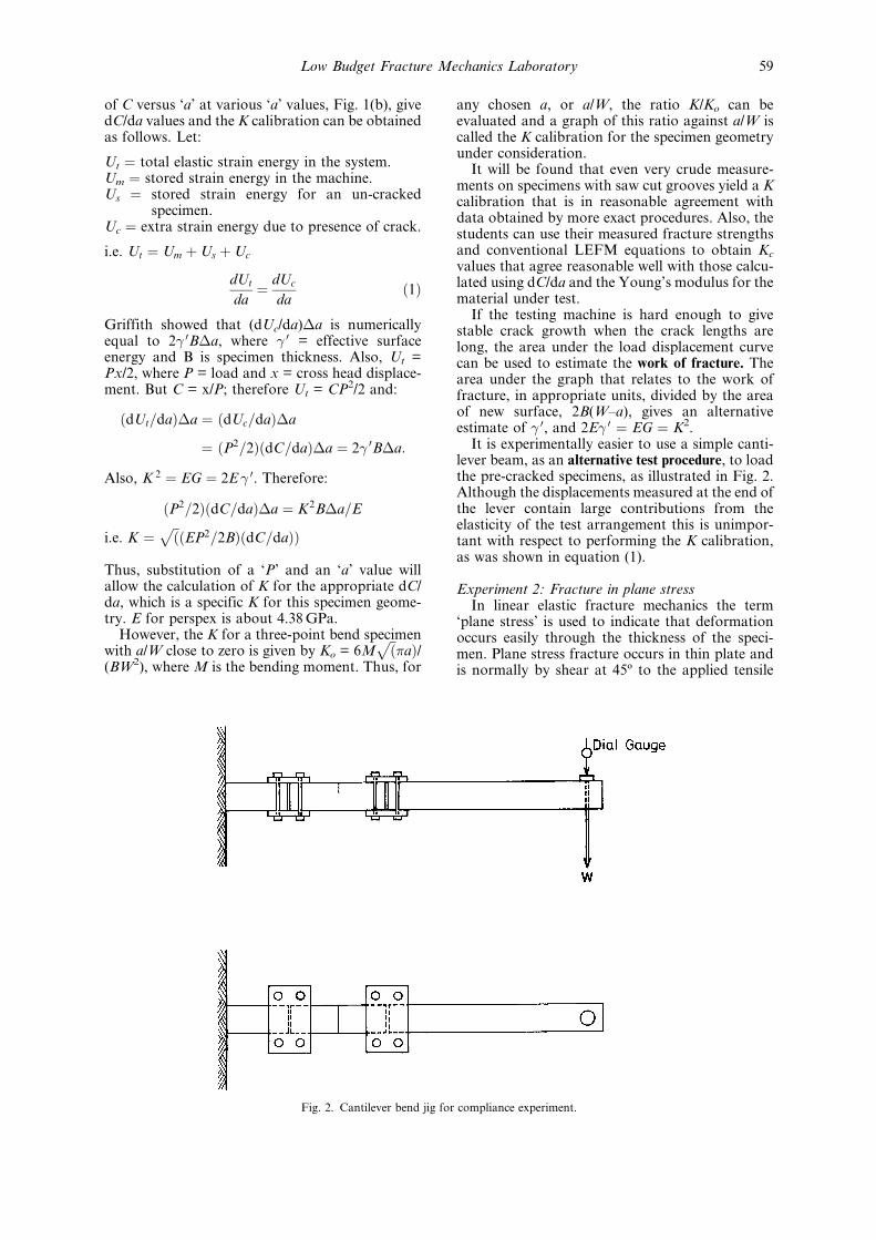
It is experimentally easier to use a simple canti-lever beam, as an alternative test procedure, to loadthe pre-cracked specimens, as illustrated in Fig. 2.Although the displacements measured at the end ofthe lever contain large contributions from theelasticity of the test arrangement this is unimpor-tant with respect to performing the K calibration,as was shown in equation (1).
Experiment 2: Fracture in plane stressIn linear elastic fracture mechanics the term
`plane stress' is used to indicate that deformationoccurs easily through the thickness of the speci-men. Plane stress fracture occurs in thin plate andis normally by shear at 45ë to the applied tensile
Fig. 2. Cantilever bend jig for compliance experiment.
Low Budget Fracture Mechanics Laboratory 59
stress. Under plane stress conditions the toughnessincreases with increasing thickness, but only to amaximum value that corresponds to the plasticzone size being similar in dimensions to the platethickness. With thicker plate than this, the tough-ness decreases again until it achieves the KIc level.Despite the shear fracture that occurs in thinplates, cold worked steel sheet can be used todemonstrate the linear relationship between the
fracture strength and the reciprocal of the squareroot of the crack length multiplied by the compli-ance correction illustrated in Experiment 1.
Samples of cold worked steel shim, width, W,and thickness, B, were used that could be cut witha pair of scissors near mid-length to generate acrack of length `a'. It is preferable to ensure that alla/W values lie within the range 0.2 < a/W < 0.6.Fracture strengths for various specimens were
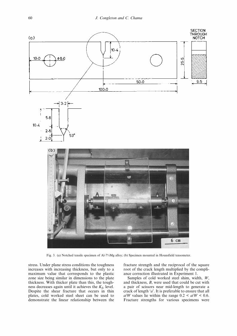
Fig. 3. (a) Notched tensile specimen of Al-7%Mg alloy; (b) Specimen mounted in Hounsfield tensometer.
J. Congleton and C. Chama60
measured and the Kc values calculated using therelevant fracture mechanics equation. For a single-edge-notched specimen, K can be calculated usingthe equation:
Kc � 5���a�1=2=�20ÿ 13�a=W� ÿ 7�a=W�2�1=2
for a specimen with a large length-to-width ratioand assuming no specimen rotation, i.e. for a platespecimen loaded using serrated jaw grips [7].
Experiment 3: Plastic zone at a crack tip underplane stress loading
Annealed shim steel specimens cut with scissorsto give a slit of length such that a/W � 0.5 can beloaded to various levels to demonstrate the devel-opment of the plastic zone at the tip of the slit. Thelength of the plastic zone as a function of appliedload can be shown to fit the theoretical estimate [8]:
ry � �
16
K2
�yield
reasonably well. A value for �yield is required. TheK can be calculated using the appropriateequation for the specimen geometry and loadingarrangement [7].
Experiment 4: Crack opening displacementIt is impossible to measure a plain strain fracture
toughness, KIc, for thin section materials of lowyield strength and high toughness because thespecimen thickness required for plain strain frac-ture is B > 2.5(K/�yield )2. Nevertheless, thin platesof tough materials can exhibit unstable crackgrowth so the toughness of such materials mustbe found. One possible approach is to assume thatfracture occurs on the achievement of a criticalstrain at the crack tip. The plastic strain at a cracktip can be characterized by the crack tip openingdisplacement (CTOD). There are various ways formeasuring this but the following experiment illus-trates the principle in the very simple way that wasused in the early days of LEFM experimentation [9].
If a thin sheet specimen of a tough metal, e.g.annealed aluminium, having two saw cut slitsspaced about 20 mm apart and of equal depth isloaded in a tensile testing machine until fracture isjust initiated at one of the slits, the necessarymeasurements can be made. A jig will be neededto cut the two equal length slits. From the load atwhich fracture just starts to propagate from the tipof one of the slits and the crack opening displace-ment measured at the other slit after the specimenis unloaded and removed from the tensile testing
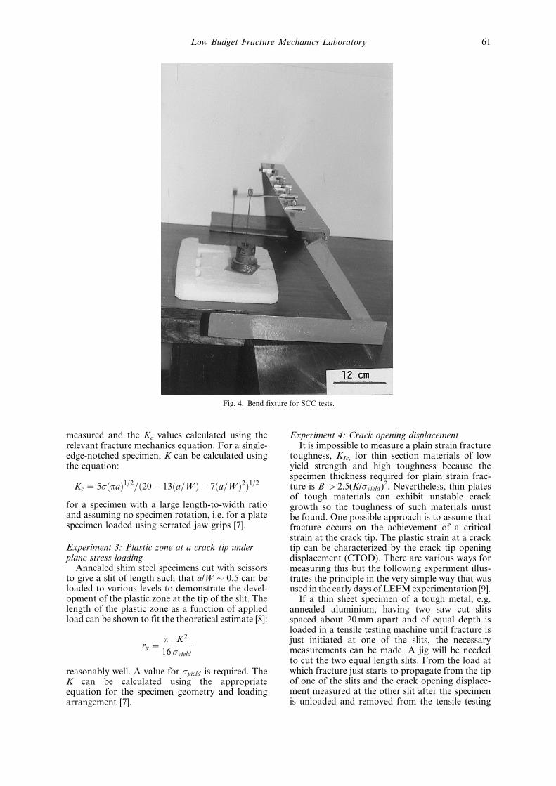
Fig. 4. Bend fixture for SCC tests.
Low Budget Fracture Mechanics Laboratory 61
machine, it is possible to estimate the toughness.The work done at the crack tip to cause fracture isthe product �yield�i, where �yield is the yield strengthof the material and �I is the crack opening displa-cement for crack initiation. The strain energyrelease rate G can be equated to �yield�i and G �K2/E. More generally, it is assumed that G �m�yield�I where m is an empirical constant thatlies in the range 0.5 to 1.06 The value of G obtainedcan be used to calculate a Kc, using the relationshipKc
2 � EG, that can be compared with the Kcalculated at the onset of fracture from themeasured fracture load P, the crack length andthe appropriate adjustment for finite specimensize. The experiment can be repeated with speci-mens of different thickness, for slits of differentlength and for cold worked material.
Experiment 5: Stress corrosion of Al-7%Mg alloyMg-7%Al alloy suffers stress corrosion cracking
in potassium chromate/sodium chloride solutions.The cracking is quite severe and occurs rapidly in20 g/L potassium chromate/20 g/L sodium chloridesolution. The heat treatment is important and isbest performed immediately before the experi-ments or only a few days before if some delay isinevitable between heat treatment and testing. Thetype of cracking depends upon the heat treatmentof the alloy. One hour at 350ëC followed by
furnace cooling causes mixed transgranular andintergranular cracking. One hour at 350ëC withwater quenching generates transgranular crackingwhereas 1 h at 350ëC � WQ � 24 h at 100ëCgenerates intergranular cracking.
An LEFM-based stress corrosion experimentcan be performed in a short time using notchedtensile specimens as illustrated in Fig. 3(a). It isimportant that the tip of the notch is re-sharpenedwith a jeweler's saw blade after the heat treatmentand that the specimen is degreased immediatelybefore testing. A small retaining cell can be madearound the notch region with adhesive tape. Thespecimen is then gripped in a Hounsfield tens-ometer and a few drops of the chromate/chloridesolution introduced to the notch. N. B. It is wise tohave a safety guard in place to protect eyes fromsplashes if the specimen breaks, Fig. 3(b). Thespecimen is loaded quickly to a maximum of9 kN for the specimen size shown in Fig. 3(a).When cracking commences the specimen compli-ance increases and the load decreases. The lattercan be allowed to reduce by about 10% of itsoriginal value, taking measurements of loadversus time, then the specimen can be quicklyunloaded and removed from the test machine.After washing away the test solution and breakingopen the specimen by gripping it in a vice andhitting it with a hammer in a direction away from
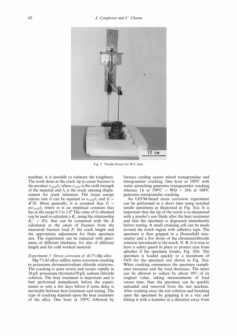
Fig. 5. Tensile fixture for SCC tests.
J. Congleton and C. Chama62
the notch and away from oneself, the extent ofstress corrosion cracking will be obvious on thefracture surface. Alternatively, load versus timemeasurements can be continued until the specimenfractures.
The K for this type of specimen can be calculatedusing the equation [10]:
K � P���ap
=BW���
p7:59ÿ 32:0�a=W�
� 117:0�a=W�2� �2�or from the appropriate graphs in Rooke andCartwright [11].
An average K for the test can be calculated fromthe initial and final K and an average crack growthfrom the amount of growth divided by the timefrom initiation to unloading or to fracture. Ifthe loading system is hard enough, a reasonableestimate of crack length can also be made from theload reading alone via an appropriate use of thedimensionless compliance of the specimen.
A series of experiments using different startingloadsforeachspecimenwillgeneratedataonaveragecrack growth rate versus average K, initiation time
as a function of applied stress and a KIc if thespecimen is allowed to break under load.
The main disadvantage of the above experimentis that the specimens are relatively costly to manu-facture and a horizontal loading frame is required.An alternative solution cell could be devised for avertical test frame. However, it is possible todemonstrate the principles of stress corrosioncracking with much simpler equipment, forinstance simple bend (Fig. 4) or tensile (Fig. 5)fixtures. The equipment required is easilyconstructed and the specimens relatively inexpen-sive to manufacture. A suitable experiment is toinvestigate time to failure as a function of appliedload. It is possible to compare the stress systemsfor tensile loading and for the notched bendarrangement and the fracture surfaces can beexamined to assess the mode of cracking.
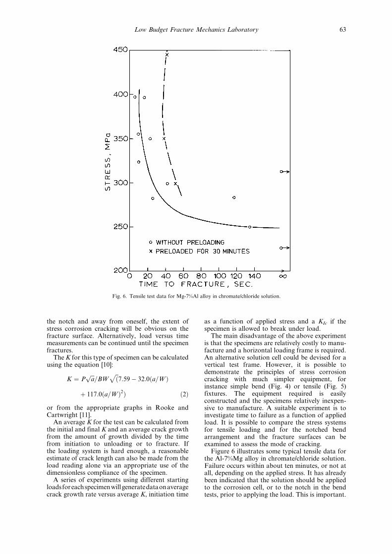
Figure 6 illustrates some typical tensile data forthe Al-7%Mg alloy in chromate/chloride solution.Failure occurs within about ten minutes, or not atall, depending on the applied stress. It has alreadybeen indicated that the solution should be appliedto the corrosion cell, or to the notch in the bendtests, prior to applying the load. This is important.
Fig. 6. Tensile test data for Mg-7%Al alloy in chromate/chloride solution.
Low Budget Fracture Mechanics Laboratory 63
If a load that will generate cracking in the absenceof solution is applied and maintained for about30 minutes, prior to application of the solution, asignificant increase in the time to fracture shouldbe seen relative to that obtained when the solutionwas present at application of the load. This isbecause stress corrosion results from the combinedeffects of plastic deformation at the crack tip andthe presence of an appropriate environment.Preloading the specimen causes significant creepexhaustion at the crack tip prior to the introduc-tion of the solution and the initiation time forstress corrosion cracking is increased.
Experiment 6: Creep of a lead-tin alloyMacroscopic creep of metals occurs at tempera-
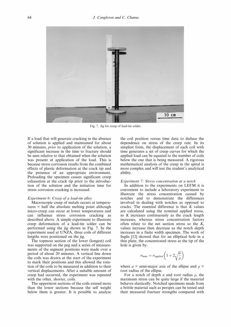
tures = half the absolute melting point althoughmicro-creep can occur at lower temperatures andcan influence stress corrosion cracking asdescribed above. A simple experiment to illustratecreep deformation of a lead-tin solder can beperformed using the jig shown in Fig. 7. In theexperiment used at UNZA, three coils of differentlengths were positioned on the jig.
The topmost section of the lower (longest) coilwas supported on the peg and a series of measure-ments of the segment positions were made over aperiod of about 20 minutes. A vertical line downthe coils was drawn at the start of the experimentto mark their positions and this allowed the rota-tion of the coils to be measured in addition to theirvertical displacements. After a suitable amount ofcreep had occurred, the experiment was repeatedwith the other, shorter, coils.
The uppermost sections of the coils extend morethan the lower sections because the self weightbelow them is greater. It is possible to analyze
the coil position versus time data to deduce thedependence on stress of the creep rate. In itssimplest form, the displacement of each coil withtime generates a set of creep curves for which theapplied load can be equated to the number of coilsbelow the one that is being measured. A rigorousmathematical analysis of the creep in the spiral ismore complex and will test the student's analyticalability.
Experiment 7: Stress concentration at a notchIn addition to the experiments on LEFM it is
convenient to include a laboratory experiment toillustrate the stress concentration caused bynotches and to demonstrate the differencesinvolved in dealing with notches as opposed tocracks. The essential difference is that K valuesare calculated using the nominal applied stress,so K increases continuously as the crack lengthincreases, whereas stress concentration factorsoften relate to the net section stress so the Kt
values increase then decrease as the notch depthincreases in a finite width specimen. The work ofInglis [12] showed that for an elliptical hole in athin plate, the concentrated stress at the tip of thehole is given by:
�max � �applied 1� 2
���a
�
r� �where a = semi-major axis of the ellipse and � =root radius of the ellipse.
For a notch of depth a and root radius �, themaximum stress can be quite large if the materialbehaves elastically. Notched specimens made froma brittle material such as perspex can be tested andtheir measured fracture strengths compared with
Fig. 7. Jig for creep of lead-tin solder.
J. Congleton and C. Chama64
those predicted by the Inglis equation and fromother texts such as that due to Peterson [13]. TheInglis equation is based on the nominal appliedstress whereas the Peterson Kt values are used withthe net section stress.
DISCUSSION
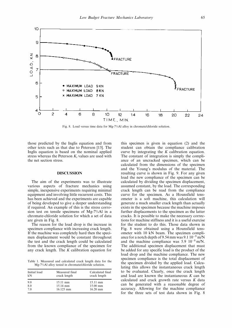
The aim of the experiments was to illustratevarious aspects of fracture mechanics usingsimple, inexpensive experiments requiring minimalequipment and involving little recurrent costs. Thishas been achieved and the experiments are capableof being developed to give a deeper understandingif required. An example of this is the stress corro-sion test on tensile specimens of Mg-7%Al in achromate-chloride solution for which a set of dataare given in Fig. 8.
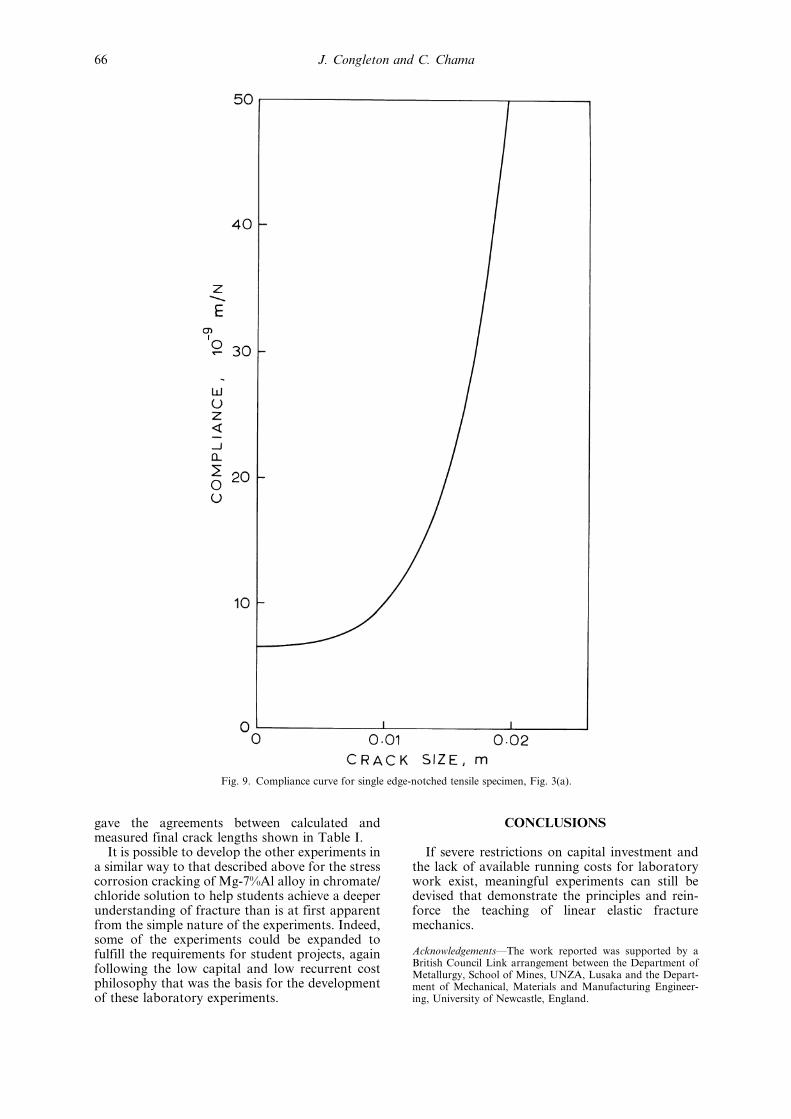
The reason for the load drop is the increase inspecimen compliance with increasing crack length.If the machine was completely hard then the speci-men displacement would be constant throughoutthe test and the crack length could be calculatedfrom the known compliance of the specimen forany crack length. The K calibration equation for
this specimen is given in equation (2) and thestudent can obtain the compliance calibrationcurve by integrating the K calibration equation.The constant of integration is simply the compli-ance of an uncracked specimen, which can becalculated from the dimensions of the specimenand the Young's modulus of the material. Theresulting curve is shown in Fig. 9. For any givenload the new compliance of the specimen can becalculated by dividing the specimen displacement,assumed constant, by the load. The correspondingcrack length can be read from the compliancecurve for the specimen. As a Hounsfield tens-ometer is a soft machine, this calculation willgenerate a much smaller crack length than actuallyexists in the specimen because the machine imposesfurther displacements to the specimen as the lattercracks. It is possible to make the necessary correc-tions for machine stiffness and it is a useful exercisefor the student to do this. Those data shown inFig. 8 were obtained using a Hounsfield tens-ometer with 10 kN beam. The specimen compli-ance for a notch depth of 9.54 mm was 9.1 10ÿ9 m/Nand the machine compliance was 5.9 10ÿ8 m/N.The additional specimen displacement that mustbe added for any specific load is the product of theload drop and the machine compliance. The newspecimen compliance is the total displacement ofthe specimen divided by the applied load. Calcu-lating this allows the instantaneous crack lengthto be evaluated. Clearly, once the crack lengthand load are known the instantaneous K can becalculated and crack growth rate versus K datacan be generated with a reasonable degree ofaccuracy. Allowing for the machine compliancefor the three sets of test data shown in Fig. 8
Fig. 8. Load versus time data for Mg-7%Al alloy in chromate/chloride solution.
Table 1. Measured and calculated crack length data for theMg-7%Al alloy tested in chromate/chloride solution.
Initial loadkN
Measured finalcrack length
Calculated finalcrack length
9.0 15.11 mm 15.11 mm8.0 15.14 mm 15.00 mm7.0 16.125 mm 16.20 mm
Low Budget Fracture Mechanics Laboratory 65
gave the agreements between calculated andmeasured final crack lengths shown in Table I.
It is possible to develop the other experiments ina similar way to that described above for the stresscorrosion cracking of Mg-7%Al alloy in chromate/chloride solution to help students achieve a deeperunderstanding of fracture than is at first apparentfrom the simple nature of the experiments. Indeed,some of the experiments could be expanded tofulfill the requirements for student projects, againfollowing the low capital and low recurrent costphilosophy that was the basis for the developmentof these laboratory experiments.
CONCLUSIONS
If severe restrictions on capital investment andthe lack of available running costs for laboratorywork exist, meaningful experiments can still bedevised that demonstrate the principles and rein-force the teaching of linear elastic fracturemechanics.
AcknowledgementsÐThe work reported was supported by aBritish Council Link arrangement between the Department ofMetallurgy, School of Mines, UNZA, Lusaka and the Depart-ment of Mechanical, Materials and Manufacturing Engineer-ing, University of Newcastle, England.
Fig. 9. Compliance curve for single edge-notched tensile specimen, Fig. 3(a).
J. Congleton and C. Chama66
REFERENCES
1. A. A. Griffith, Phil. Trans. Roy. Soc., A, 222 (1921) p. 180.2. A. A. Griffith, Proc. Int. Conf. Appl. Mech. (Delft) (1924) p. 55.3. E. Orowan, Trans. Inst. Engns. Shipbuilders Scotland, 89 (1945) p. 165.4. G. R. Irwin, 9th Inter. Congr. Appl. Mech., VIII, Paper 101 (II), University of Brussels (1957)
p. 245.5. I. Milne, R. A. Ainsworth, A. R. Dowling and A. T. Stewart, Assessment of the Integrity of
Structures Containing Defects, Report R/H/R6, Rev. 3 (1976).6. J. Knott and P. Withey, Fracture Mechanics, Worked Examples, Institute of materials (1993).7. D. O. Harris, Jour. Basic Eng., 89 (1967) p. 49.8. D. S. Dugdale, Jour. Mech. Phys. Solids, 8 (1960) p. 100.9. J. F. Knott, J. Iron and Steel Inst., 204 (1966) p. 1014.
10. H. R. Smith and D. E. Piper, Stress Corrosion Testing with Precracked Specimens, Boeing ReportD6-24872, ARPA order No. 878 (June 1970) p. 20.
11. D. P. Rooke and D. J. Cartwright, Compendium of Stress Intensity Factors, H.M.S.O., London,(1976).
12. C. E. Inglis, Trans. Nav. Arch., 55 (1913) p. 219.13. R. E. Peterson, Stress Concentration Design Factors, Wiley, New York (1963).
C. C. Chama obtained his bachelor's degree in Metallurgy and Mineral Processing from theUniversity of Zambia in November 1980, an M. Sc. in March 1983 and a Ph. D. inDecember 1986 from The Pennsylvania State University in Mechanical and PhysicalMetallurgy. In April 1987 he took up a teaching post in Physical Metallurgy at theUniversity of Zambia where he is presently a senior lecturer. Apart from teaching, DrChama does consultancy work for the local industry in Zambia in mechanical testing andhas been Head of the Department of Metallurgy and Mineral processing, and AssistantDean of Postgraduate Studies.
J. Congleton obtained an Honours Degree in Metallurgy from Kings College, University ofDurham (now the University of Newcastle) in 1956 and a Ph. D. there in 1960. After a shortperiod in industry he returned to Newcastle as a Research Assistant to Professor N. J.Petch, then was appointed to a lectureship then a Senior Lectureship in 1972. He remainedat Newcastle until he retired in 1997. Dr Congleton has worked on various aspects of brittlefracture of materials while at Newcastle. His Ph. D. was in Creep of aluminium alloys.From 1960 to about 1975 he worked on the brittle fracture of metals and ceramics and wasparticularly interested in fast fracture and crack bifurcation. In about 1975 he changed hisinterests to environment assisted cracking, initially working on corrosion fatigue but lateron stress corrosion of materials used in civil nuclear power plant. He has been involved inseveral British Council supported collaborative programmes with establishments in Chinaand in Zambia. The present paper arose from the latter.
Low Budget Fracture Mechanics Laboratory 67